EP3917643B1 - Blasenfalle - Google Patents
Blasenfalle Download PDFInfo
- Publication number
- EP3917643B1 EP3917643B1 EP19706387.8A EP19706387A EP3917643B1 EP 3917643 B1 EP3917643 B1 EP 3917643B1 EP 19706387 A EP19706387 A EP 19706387A EP 3917643 B1 EP3917643 B1 EP 3917643B1
- Authority
- EP
- European Patent Office
- Prior art keywords
- chamber
- diverter
- gas
- fluid
- tube
- Prior art date
- Legal status (The legal status is an assumption and is not a legal conclusion. Google has not performed a legal analysis and makes no representation as to the accuracy of the status listed.)
- Active
Links
Images








Classifications
-
- A—HUMAN NECESSITIES
- A61—MEDICAL OR VETERINARY SCIENCE; HYGIENE
- A61M—DEVICES FOR INTRODUCING MEDIA INTO, OR ONTO, THE BODY; DEVICES FOR TRANSDUCING BODY MEDIA OR FOR TAKING MEDIA FROM THE BODY; DEVICES FOR PRODUCING OR ENDING SLEEP OR STUPOR
- A61M5/00—Devices for bringing media into the body in a subcutaneous, intra-vascular or intramuscular way; Accessories therefor, e.g. filling or cleaning devices, arm-rests
- A61M5/36—Devices for bringing media into the body in a subcutaneous, intra-vascular or intramuscular way; Accessories therefor, e.g. filling or cleaning devices, arm-rests with means for eliminating or preventing injection or infusion of air into body
-
- A—HUMAN NECESSITIES
- A61—MEDICAL OR VETERINARY SCIENCE; HYGIENE
- A61M—DEVICES FOR INTRODUCING MEDIA INTO, OR ONTO, THE BODY; DEVICES FOR TRANSDUCING BODY MEDIA OR FOR TAKING MEDIA FROM THE BODY; DEVICES FOR PRODUCING OR ENDING SLEEP OR STUPOR
- A61M1/00—Suction or pumping devices for medical purposes; Devices for carrying-off, for treatment of, or for carrying-over, body-liquids; Drainage systems
- A61M1/36—Other treatment of blood in a by-pass of the natural circulatory system, e.g. temperature adaptation, irradiation ; Extra-corporeal blood circuits
- A61M1/3621—Extra-corporeal blood circuits
- A61M1/3627—Degassing devices; Buffer reservoirs; Drip chambers; Blood filters
- A61M1/3633—Blood component filters, e.g. leukocyte filters
-
- A—HUMAN NECESSITIES
- A61—MEDICAL OR VETERINARY SCIENCE; HYGIENE
- A61M—DEVICES FOR INTRODUCING MEDIA INTO, OR ONTO, THE BODY; DEVICES FOR TRANSDUCING BODY MEDIA OR FOR TAKING MEDIA FROM THE BODY; DEVICES FOR PRODUCING OR ENDING SLEEP OR STUPOR
- A61M1/00—Suction or pumping devices for medical purposes; Devices for carrying-off, for treatment of, or for carrying-over, body-liquids; Drainage systems
- A61M1/36—Other treatment of blood in a by-pass of the natural circulatory system, e.g. temperature adaptation, irradiation ; Extra-corporeal blood circuits
- A61M1/3621—Extra-corporeal blood circuits
- A61M1/3627—Degassing devices; Buffer reservoirs; Drip chambers; Blood filters
-
- A—HUMAN NECESSITIES
- A61—MEDICAL OR VETERINARY SCIENCE; HYGIENE
- A61M—DEVICES FOR INTRODUCING MEDIA INTO, OR ONTO, THE BODY; DEVICES FOR TRANSDUCING BODY MEDIA OR FOR TAKING MEDIA FROM THE BODY; DEVICES FOR PRODUCING OR ENDING SLEEP OR STUPOR
- A61M5/00—Devices for bringing media into the body in a subcutaneous, intra-vascular or intramuscular way; Accessories therefor, e.g. filling or cleaning devices, arm-rests
- A61M5/14—Infusion devices, e.g. infusing by gravity; Blood infusion; Accessories therefor
- A61M5/1411—Drip chambers
-
- A—HUMAN NECESSITIES
- A61—MEDICAL OR VETERINARY SCIENCE; HYGIENE
- A61M—DEVICES FOR INTRODUCING MEDIA INTO, OR ONTO, THE BODY; DEVICES FOR TRANSDUCING BODY MEDIA OR FOR TAKING MEDIA FROM THE BODY; DEVICES FOR PRODUCING OR ENDING SLEEP OR STUPOR
- A61M5/00—Devices for bringing media into the body in a subcutaneous, intra-vascular or intramuscular way; Accessories therefor, e.g. filling or cleaning devices, arm-rests
- A61M5/14—Infusion devices, e.g. infusing by gravity; Blood infusion; Accessories therefor
- A61M5/165—Filtering accessories, e.g. blood filters, filters for infusion liquids
-
- A—HUMAN NECESSITIES
- A61—MEDICAL OR VETERINARY SCIENCE; HYGIENE
- A61M—DEVICES FOR INTRODUCING MEDIA INTO, OR ONTO, THE BODY; DEVICES FOR TRANSDUCING BODY MEDIA OR FOR TAKING MEDIA FROM THE BODY; DEVICES FOR PRODUCING OR ENDING SLEEP OR STUPOR
- A61M5/00—Devices for bringing media into the body in a subcutaneous, intra-vascular or intramuscular way; Accessories therefor, e.g. filling or cleaning devices, arm-rests
- A61M5/36—Devices for bringing media into the body in a subcutaneous, intra-vascular or intramuscular way; Accessories therefor, e.g. filling or cleaning devices, arm-rests with means for eliminating or preventing injection or infusion of air into body
- A61M5/38—Devices for bringing media into the body in a subcutaneous, intra-vascular or intramuscular way; Accessories therefor, e.g. filling or cleaning devices, arm-rests with means for eliminating or preventing injection or infusion of air into body using hydrophilic or hydrophobic filters
-
- A—HUMAN NECESSITIES
- A61—MEDICAL OR VETERINARY SCIENCE; HYGIENE
- A61M—DEVICES FOR INTRODUCING MEDIA INTO, OR ONTO, THE BODY; DEVICES FOR TRANSDUCING BODY MEDIA OR FOR TAKING MEDIA FROM THE BODY; DEVICES FOR PRODUCING OR ENDING SLEEP OR STUPOR
- A61M5/00—Devices for bringing media into the body in a subcutaneous, intra-vascular or intramuscular way; Accessories therefor, e.g. filling or cleaning devices, arm-rests
- A61M5/36—Devices for bringing media into the body in a subcutaneous, intra-vascular or intramuscular way; Accessories therefor, e.g. filling or cleaning devices, arm-rests with means for eliminating or preventing injection or infusion of air into body
- A61M5/38—Devices for bringing media into the body in a subcutaneous, intra-vascular or intramuscular way; Accessories therefor, e.g. filling or cleaning devices, arm-rests with means for eliminating or preventing injection or infusion of air into body using hydrophilic or hydrophobic filters
- A61M5/385—Devices for bringing media into the body in a subcutaneous, intra-vascular or intramuscular way; Accessories therefor, e.g. filling or cleaning devices, arm-rests with means for eliminating or preventing injection or infusion of air into body using hydrophilic or hydrophobic filters using hydrophobic filters
-
- B—PERFORMING OPERATIONS; TRANSPORTING
- B01—PHYSICAL OR CHEMICAL PROCESSES OR APPARATUS IN GENERAL
- B01D—SEPARATION
- B01D19/00—Degasification of liquids
- B01D19/0031—Degasification of liquids by filtration
-
- B—PERFORMING OPERATIONS; TRANSPORTING
- B01—PHYSICAL OR CHEMICAL PROCESSES OR APPARATUS IN GENERAL
- B01D—SEPARATION
- B01D19/00—Degasification of liquids
- B01D19/0042—Degasification of liquids modifying the liquid flow
Definitions
- a gas bubble endeavours to maintain integral shape; however, it may become deformed and elongated under duress, such as being sucked into a narrow tube.
- the gas bubble will try to return to a rounder ball shape where possible, unless restricted, such as happens in tubing. Gas bubbles therefore tend to adhere to the internal walls of long tubing and deform from the preferred round shape to an elongated oval shape.
- the primary IV drip bag 104 is connected to primary IV tubing 110,
- the primary IV tubing 110 typically comprises a sterile spike 112, a drip chamber 114, a back-check valve 116, at least one port 118 120, a slider clamp 122 and a roller clamp 124.
- the primary IV tubing 110 is connected to extension tubing 126 via a luer lock 128. While a luer lock has been described, it is to be appreciated that other securing means, such as a push-fit connection, may also be used.
- the extension tubing 126 connects to a cannula 130 and may also comprise a damp 132.
- the liquid solution in the IV drip typically flows under the influence of a gravity pressure gradient (i.e. from high pressure to low pressure) from the IV drip bag 104 suspended from the top of the IV pole 102, through to the cannula 130, wherein the IV drip solution enters the blood stream of the patient, the patient generally being positioned lower than the IV drip bag 164.
- a gravity pressure gradient i.e. from high pressure to low pressure
- fluid shall be understood to encompass both a liquid phase and a gas phase, wherein the gas is entrained or introduced to the liquid phase.
- a Murphy Dropper 114 has dual functionality in that it first enables observation of the fluid flow rate and secondly to remove risk of air or gas that may have formed in the bag from entering the flexible tubing.
- Such drip chambers 114 may have a ball that floats on the fluid, the purpose of which is to block the entrance to the flexible tube should the bag 104, 134 empty of fluids, a situation which could cause an excess of air to become entrained in the line. This air would present a serious complication to a patient if the line was placed in the vein and the entrained air was not observed.
- Drip chambers 114, such as the Murphy Dropper tend to be located at the top of the line, just below the IV drip bag 104, 134.
- This position is intentional to enable ease of access and means to manually purge the drip chamber 114 of air that has collected therein.
- the position is furthest from the entry point to the patient (i.e. the cannula 130) and degassing of fluids and entrainment of air is possible throughout the length of the line, meaning that it is possible for air bubbles to form after the solution has passed through the drip chamber 114 and enter the bloodstream via the cannula 130 into the patient's vein.
- Such IV drip set-ups typically require constant visual monitoring and manual removal of the gas bubbles, which is time-consuming, labour-intensive and erratic, subject to human error. Removal of bubbles tends to require removal of a proportion of the IV drip solution to ensure the gas does not enter the body of the patient, which is wasteful of hospital resources.
- extension tubing It is common for extension tubing to be added to an IV set in situations where the location of the IV stand is inconvenient to have near to the bed, typically during surgeries with multiple staff present. In this case, the extended tubing may provide further challenges for clinical staff to observe the bubbles contained within the tube and also gives additional volume of fluids from which gas can defuse.
- Air can be further introduced into the closed system by staff injecting supplementary medications into the infusion liquid solution at any location between the IV bag and the point of entry into the patient.
- the bubble trap of US 6,537,356 is described as intended to be disposable, and as such is not suitable for repeated or continuous use. The user would therefore need to keep watch and move the device into another position to prolong its one-time usage time, as too long in one position would result in the centrally located tube no longer being submerged in the fluid, leading to air entering the outlet nozzle and into the blood stream of a patient.
- a further disadvantage of the bubble trap as described in US 6,537,356 is that air present in the device before use may not be readily flushed from the device prior to use, meaning that the device will not work as efficiently nor for a long duration limiting its operational capacity.
- inlet tubing 208 or outlet tubing 210 may be present.
- Fluid that is now substantially free from bubbles, collects between the diverter 402 and the intake end 306 of the elongated exit tube 304.
- the fluid substantially free from bubbles locates centrally within the chamber 302 and may be understood to be slower moving than fluid moving along the outer portions of the chamber 302. Fluid, substantially free from bubbles, exits the apparatus 200 via the outlet port 206 and moves along the outlet tubing 210 away from the apparatus 200.
- Entrained gas in the form of bubbles pass through a volume of fluid within the chamber 302 and friction exerted on the outer surface of the bubble increases resulting in the trajectory being altered, such that buoyancy becomes the dominant force moving the bubble towards the uppermost outer portion of the chamber 302.
- Fluid that is now substantially free from bubbles, collects between the diverter 402 and the intake end 306 of the elongated exit tube 304.
- the fluid substantially free from bubbles locates centrally within the chamber 302 and may be understood to be slower moving than fluid moving along the outer portions of the chamber 302.
- the fluid substantially free from bubbles is then drawn into the intake end 306 of the elongated exit tube 304 and exits the chamber 302 via the outlet port 206 and away from the apparatus 900.
- the diffuser 902 is formed of a plurality of holes spaced apart and positioned in a generally radial arrangement about the circumference of the diffuser 902.
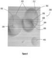
- the diverter 402 obstructs the first direction of flow of the fluid and entrained gas and causes a change in direction of the fluid and entrained gas, diverting it away from its original path (or first direction of flow) in a generally outward direction and away from the intake end 306 of the elongated exit tube 304.
- the diverter 402 causes the fluid velocity to slow and thus the entrained gas bubbles also slow. This has the effect of causing a change to the external forces applied to the membrane of the gas bubble, such that buoyancy becomes the dominant force. As buoyancy becomes the dominant force the entrained gas bubbles move in a generally outward and upward direction and away from the intake end 306 of the elongated exit tube 304.
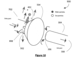
- the apparatus 1000 comprises an inflow tube 702, a diffuser 902, a diverter 402, the diverter 402 having a base portion 502 and a rim 504, and an elongated exit tube 304, the elongated exit tube 304 having an intake end 306 and an export end 308.
- the inflow tube 702 is positioned such that it connected to a portion of the diverter 402 by a tether 708 forming a diffuser 902 comprising at least one hole.
- inflow tube 702, diffuser 902 and diverter 402 are integrated forming at least one hole.
- inflow tube 702, diffuser 902 and diverter 402 are integrated forming a plurality of holes. In this embodiment three holes can be seen.
- the apparatus 1200 comprises a housing 202, an inlet port 204 and an outlet port 206.
- the apparatus is shown to comprise a venting port 212 and a foot 1202.
- the foot 1202 is connected to a portion of the housing 202.
- the foot 1202 may be used to rest the otherwise generally spherical apparatus on a substantially flat surface.
- the foot 1202 may be used as a means to secure the apparatus to a surface, such as a patient, bed, pillow or any portion of an IV drip set-up 100.
- Paediatric care was identified as a high priority.
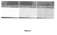
- Bubble formation patterns were observed, such as coalescence and pocketing, in response to line placement, height, direction and volume of gas developed. Temperate and flow rate were adjusted to identify the role that each play in the formation of bubbles in an IV line.
- the Flow Rate vs Gas Volume line of Figure 15 (diamond) graphically forms a very irregular shape due to the erratic scatter of the values.
- the trendline for this graph shows a rise and fall hill shape, an order 2 polynomial.
- Figure 16 shows the correlation of gas volume (dark grey; spotted) versus bag temperature (light grey; diagonal lines).
- the maximum level was determined from testing where a maximum reading of 2.4ml/1000ml was taken with a built-in factor of 5X an average reading was calculated to allow at least a 15ml gas capacity, for safety reasons.
- the apparatus can collect up to 15mls of gas before gas levels reach a level where the apparatus will no longer function effectively and before the gas level reaches the elongated exit tube. This means that up to 5 bags of fluids could be infused concurrently at maximum degassing levels.
- the recommended gas level can vary from zero (e.g. no gas is preferred in Paediatrics due to reduced blood volume and natural 'hole-in-the-heart' present in infants) to 3ml/kg of body weight in healthy adults (tests conducted on animals) with adverse effects possible from 1ml/kg of air injected.
- the body can tolerate some gas (if there are no underlying conditions) in ideal conditions but it is preferable to have no gas enter any patient, if possible.
- Recent studies cite damage to the Endothelial Glycocalyx layer of the vasculature as a reason to prevent gas bubbles from entering the venous system.
- the tap on the IV line is closed and the hotline L1 remains off throughout the whole experiment so as to avoid unwanted gas production that would otherwise hinder the experiment.
- the IV drip bag is hung from the top of the IV stand and connected to the IV line.
- the prototype undergoing testing is connected to the end of the lumen line closest to the patient and the extension line is connected to the other end of the prototype.
- the clave connector is then attached to the gas extraction port. Lines are drawn on a piece of paper with angles of 45, 90, 180, 225, 270, 315 and 360 degrees and the piece of paper is attached to a flat vertical surface.
- a plastic container is filled with water.
- a small graduated cylinder is filled with water, making sure that the graduated cylinder is connected to the plastic container using an attachment.
- the end of the extension line is placed into the graduated cylinder, before the graduated cylinder is rapidly turned upside down into the plastic container so that no liquid escapes the cylinder and the graduated cylinder attachment rests perfectly on the rim of the container ensuring that the cylinder remains vertical during the experiment.
- the initial reading (zero) of gas on the upside down graduated cylinder is read and recorded.
- the tap is then turned on to allow liquid to flow from the bag ensuring that it is at the maximum possible flow rate.
- Gas trapped in the chamber of the prototype undergoing testing is removed using a syringe inserted via the clave connector. Once all the gas has been extracted the prototype section of the line is attached to the flat vertical surface so that it is parallel to the 45 degree angle line previously drawn on the paper.
- the syringe is filled with 1ml of air and injected into the IV line next to the hotline L1 so that the gas flows towards the prototype. Gas passing through the prototype into the extension line is observed and the value of gas gathered in the graduated cylinder is recorded. If no gas is observed, then the value is recorded as 0. The experiment is repeated for volumes of air up to 20ml going up in increments of 1ml and then for each of the following angles: 90, 180, 225, 270, 315 and 380 degrees.
- a device of the present invention may be adapted for use in other applications, such as but not limited to, use in blood transfusion apparatus and any other fluid treatment set-up where entrained gas requires removing, capturing or expelling.
Landscapes
- Health & Medical Sciences (AREA)
- Heart & Thoracic Surgery (AREA)
- Vascular Medicine (AREA)
- General Health & Medical Sciences (AREA)
- Veterinary Medicine (AREA)
- Biomedical Technology (AREA)
- Engineering & Computer Science (AREA)
- Hematology (AREA)
- Life Sciences & Earth Sciences (AREA)
- Animal Behavior & Ethology (AREA)
- Anesthesiology (AREA)
- Public Health (AREA)
- Emergency Medicine (AREA)
- Cardiology (AREA)
- Chemical & Material Sciences (AREA)
- Chemical Kinetics & Catalysis (AREA)
- External Artificial Organs (AREA)
- Infusion, Injection, And Reservoir Apparatuses (AREA)
- Degasification And Air Bubble Elimination (AREA)
- Gas Separation By Absorption (AREA)
Claims (10)
- Vorrichtung, die zum Trennen und Sammeln von in einem Fluid mitgeführten Gasblasen geeignet ist, wobei die Vorrichtung Folgendes umfasst:ein Gehäuse, das mindestens eine Kammer (202) definiert, wobei die Kammer eine Einlassöffnung (204) und eine Auslassöffnung (206) aufweist;eine langgestreckte Austrittsröhre (206, 304) mit einem Aufnahmeende (306) und einem Ausgabeende (210, 308),wobei sich das Aufnahmeende der langgestreckten Austrittsröhre mittig innerhalb der Kammer befindet und das Ausgabeende (210, 308) der langgestreckten Austrittsröhre mit der Auslassöffnung der Kammer verbunden ist,dadurch gekennzeichnet, dassdie Vorrichtung Folgendes umfasst:eine Zuflussröhre (702) mit einem Aufnahmeende (706) und einem Ausgabeende (704), wobei sich das Ausgabeende mittig innerhalb der Kammer befindet und ein Aufnahmeende (706) der Zuflussröhre mit der Einlassöffnung (204) verbunden ist,einen Diffusor undeinen zwischen der Einlassöffnung und der Auslassöffnung positionierten Umleiter (402), wobei der Umleiter einen Basisabschnitt (502) und einen Rand (504) umfasst und wobei der Rand (504) des Umleiters (402) zwischen dem Basisabschnitt (502) des Umleiters (402) und dem Aufnahmeende (306) der langgestreckten Austrittsröhre (304) positioniert ist,das Ausgabeende (704) der Zuflussröhre an den Basisabschnitt des Umleiters grenzt und der Diffusor aus der Zuflussröhre gebildet wird und eine Vielzahl von Löchern (704) umfasst, die beabstandet sind und in einer allgemein radialen Anordnung um einen Umfang des Diffusors herum positioniert sind, wobei die Zuflussröhre (702), der Diffusor (704) und der Umleiter (402, 502, 504) integriert sind, oderdie Zuflussröhre durch ein Halteband (708) mit einem Abschnitt des Umleiters (402) verbunden ist, wobei das Halteband den Diffusor bildet und der Diffusor mindestens ein Loch (704) umfasst.
- Vorrichtung nach Anspruch 1, wobei der Umleiter (402) einen Teilraum definiert.
- Vorrichtung nach einem der Ansprüche 1 und 2, wobei der Umleiter (402) abgerundete Konturen aufweist.
- Vorrichtung nach Anspruch 1 oder 2 oder 3, wobei die Vorrichtung mindestens eine Innenoberfläche umfasst, wobei ein Abschnitt der mindestens einen Innenoberfläche eine Oberflächenbehandlung umfasst, wobei die Oberflächenbehandlung für die Steuerung einer Blase und von deren Bewegung innerhalb der Kammer geeignet ist.
- Vorrichtung nach einem der vorhergehenden Ansprüche, wobei die Vorrichtung mindestens eine zum Entfernen von eingeschlossenen Gasblasen aus der Vorrichtung geeignete Abzugsöffnung umfasst.
- Vorrichtung nach Anspruch 5, wobei die Abzugsöffnung eine gasdurchlässige/wasserundurchlässige Membran umfasst, sodass eingeschlossenes Gas bei der Verwendung die gasdurchlässige/wasserundurchlässige Membran durchquert und aus der Kammer entfernt wird, während Wasser innerhalb der Kammer der Vorrichtung zurückgehalten wird.
- Vorrichtung nach einem der vorhergehenden Ansprüche, wobei die Vorrichtung in einem Kreislauf angeordnet ist.
- Vorrichtung nach einem der vorhergehenden Ansprüche, wobei die Vorrichtung eine Vielzahl von in einer Reihe angeordneten Kammern umfasst.
- Vorrichtung nach einem vorhergehenden Anspruch, wobei die Kammer kugelförmig ist.
- Kit für einen intravenösen Zugang, wobei das Kit Folgendes umfasst:mindestens einen Tropfinfusionsbeutel;mindestens eine Tropfkammer;mindestens eine Zufuhrröhre mit einem proximalen Ende und einem distalen Ende;eine Blasenfalle, die eine Vorrichtung nach einem der Ansprüche 1 bis 9 umfasst;eine Fluiddurchflussregelungseinrichtung;mindestens eine Klemme; undeine Kanüle.
Priority Applications (1)
| Application Number | Priority Date | Filing Date | Title |
|---|---|---|---|
| EP24178297.8A EP4397335A3 (de) | 2019-01-30 | 2019-01-30 | Blasenfallenvorrichtung |
Applications Claiming Priority (1)
| Application Number | Priority Date | Filing Date | Title |
|---|---|---|---|
| PCT/EP2019/052299 WO2020156666A1 (en) | 2019-01-30 | 2019-01-30 | A bubble trap device |
Related Child Applications (2)
| Application Number | Title | Priority Date | Filing Date |
|---|---|---|---|
| EP24178297.8A Division-Into EP4397335A3 (de) | 2019-01-30 | 2019-01-30 | Blasenfallenvorrichtung |
| EP24178297.8A Division EP4397335A3 (de) | 2019-01-30 | 2019-01-30 | Blasenfallenvorrichtung |
Publications (2)
| Publication Number | Publication Date |
|---|---|
| EP3917643A1 EP3917643A1 (de) | 2021-12-08 |
| EP3917643B1 true EP3917643B1 (de) | 2024-07-03 |
Family
ID=65516463
Family Applications (2)
| Application Number | Title | Priority Date | Filing Date |
|---|---|---|---|
| EP19706387.8A Active EP3917643B1 (de) | 2019-01-30 | 2019-01-30 | Blasenfalle |
| EP24178297.8A Pending EP4397335A3 (de) | 2019-01-30 | 2019-01-30 | Blasenfallenvorrichtung |
Family Applications After (1)
| Application Number | Title | Priority Date | Filing Date |
|---|---|---|---|
| EP24178297.8A Pending EP4397335A3 (de) | 2019-01-30 | 2019-01-30 | Blasenfallenvorrichtung |
Country Status (5)
| Country | Link |
|---|---|
| US (2) | US12239773B2 (de) |
| EP (2) | EP3917643B1 (de) |
| JP (2) | JP7321276B2 (de) |
| CN (1) | CN113365712B (de) |
| WO (1) | WO2020156666A1 (de) |
Families Citing this family (11)
| Publication number | Priority date | Publication date | Assignee | Title |
|---|---|---|---|---|
| EP3917643B1 (de) | 2019-01-30 | 2024-07-03 | Tessen Solutions Limited | Blasenfalle |
| WO2023044416A1 (en) * | 2021-09-17 | 2023-03-23 | Life Technologies Corporation | 3d printed bubble traps and methods of manufacture |
| AU2022252836A1 (en) * | 2021-10-25 | 2023-05-11 | Fresenius Kabi Usa, Llc | Pressure-assisted air elimination |
| WO2023148100A1 (en) | 2022-02-02 | 2023-08-10 | Tessen Solutions Limited | Gas trap device |
| CN119278380A (zh) * | 2022-03-11 | 2025-01-07 | W.L.戈尔及同仁股份有限公司 | 气体分离装置 |
| USD1104257S1 (en) | 2022-09-16 | 2025-12-02 | Life Technologies Corporation | Bubble trap |
| US20240110886A1 (en) * | 2022-09-29 | 2024-04-04 | Rosemount Inc. | Amperometric sensor with bubble shedding clip |
| WO2024156823A1 (en) | 2023-01-27 | 2024-08-02 | Tessen Solutions Limited | Gas control in medical fluid filters |
| WO2024223789A1 (en) | 2023-04-27 | 2024-10-31 | Tessen Solutions Limited | A pre-primed giving set and compounding apparatus' and methods |
| CN116459412B (zh) * | 2023-05-06 | 2025-01-24 | 中国人民解放军联勤保障部队第九六〇医院 | 一种直升机救援护理用输液装置 |
| WO2025202381A1 (en) | 2024-03-28 | 2025-10-02 | Tessen Solutions Limited | A gas trap device |
Citations (1)
| Publication number | Priority date | Publication date | Assignee | Title |
|---|---|---|---|---|
| US5674199A (en) * | 1993-11-29 | 1997-10-07 | Cobe Laboratories, Inc. | Top flow bubble trap method |
Family Cites Families (30)
| Publication number | Priority date | Publication date | Assignee | Title |
|---|---|---|---|---|
| US3803810A (en) * | 1972-05-01 | 1974-04-16 | Pall Corp | Liquid-gas separator and filter |
| US3827561A (en) | 1972-09-20 | 1974-08-06 | Milton Roy Co | Deaerator for dialysis system |
| US4048995A (en) | 1975-08-15 | 1977-09-20 | Baxter Travenol Laboratories, Inc. | Injection site |
| JPS589606Y2 (ja) * | 1978-06-27 | 1983-02-22 | 株式会社荏原製作所 | 圧力タンク |
| AU6249180A (en) | 1979-09-18 | 1981-04-09 | Millipore Corp. | Automatic dual rate i.v. administration |
| DE3176446D1 (en) * | 1980-09-01 | 1987-10-22 | Ici Plc | Centrifugal gas-liquid contact apparatus |
| JPS60186002U (ja) * | 1984-05-21 | 1985-12-10 | 本間 慶蔵 | 抜気消音装置 |
| US4795457A (en) | 1987-05-08 | 1989-01-03 | C. R. Bard, Inc. | Venous reservoir |
| DE4039824C1 (de) * | 1990-12-13 | 1991-12-19 | Ieg - Industrie-Engineering Gmbh, 7410 Reutlingen, De | |
| US6537356B1 (en) | 1999-08-06 | 2003-03-25 | Nathaniel M. Soriano | Gas and solid trap for an intravenous line |
| US6508859B1 (en) | 2000-11-13 | 2003-01-21 | Porous Media Corporation | Method and apparatus for removing air or gas from fluid |
| US20060173395A1 (en) | 2002-02-12 | 2006-08-03 | Brugger James M | Set for blood processing |
| JP2004122066A (ja) * | 2002-10-07 | 2004-04-22 | Dainippon Screen Mfg Co Ltd | 脱気装置 |
| US7141097B2 (en) | 2003-01-15 | 2006-11-28 | Filtertek Inc. | Bacterial retentive, air venting, intravenous filter |
| CA2544612C (en) | 2003-11-24 | 2011-12-20 | Gambro Lundia Ab | Degassing device and end-cap assembly for a filter including such a degassing device |
| US7279031B1 (en) * | 2003-11-25 | 2007-10-09 | Wright David W | Emboli elimination apparatus |
| US20050247198A1 (en) * | 2004-05-07 | 2005-11-10 | Kent Fraser C | Method and apparatus for removing gas bubbles from a liquid |
| US8613725B2 (en) * | 2007-04-30 | 2013-12-24 | Medtronic Minimed, Inc. | Reservoir systems and methods |
| JP2010064007A (ja) | 2008-09-11 | 2010-03-25 | Ricoh Co Ltd | 粘性液体の脱気方法及び脱気装置、感熱記録体塗料の作製方法、並びに感熱記録媒体 |
| IE20100791A1 (en) * | 2009-12-22 | 2011-08-31 | Cork Inst Technology | A bubble entrapment device |
| US9457158B2 (en) | 2010-04-12 | 2016-10-04 | Q-Core Medical Ltd. | Air trap for intravenous pump |
| EP2463004B1 (de) | 2010-12-08 | 2013-11-20 | AFRISO-Euro-Index GmbH | Gasabscheider |
| JP2012249781A (ja) * | 2011-06-02 | 2012-12-20 | Nagasaki Institute Of Applied Science | 気泡除去装置 |
| US8632624B2 (en) * | 2011-10-13 | 2014-01-21 | General Electric Company | Fluid trap and method of separating fluids |
| US10279126B2 (en) * | 2014-10-07 | 2019-05-07 | Medtronic Minimed, Inc. | Fluid conduit assembly with gas trapping filter in the fluid flow path |
| US20160346485A1 (en) | 2015-05-27 | 2016-12-01 | Vital Signs, Inc. | Apparatus and methods for intravenous gas elimination |
| CA3025620A1 (en) * | 2016-05-27 | 2017-11-30 | Vital Signs, Inc. | Apparatus and methods for intravenous gas elimination |
| WO2020095309A1 (en) * | 2018-11-10 | 2020-05-14 | Ezmems Ltd. | Detachable sensor devices |
| EP3917643B1 (de) | 2019-01-30 | 2024-07-03 | Tessen Solutions Limited | Blasenfalle |
| US20230321363A1 (en) | 2020-07-29 | 2023-10-12 | Tessen Solutions Limited | Infusion apparatus |
-
2019
- 2019-01-30 EP EP19706387.8A patent/EP3917643B1/de active Active
- 2019-01-30 WO PCT/EP2019/052299 patent/WO2020156666A1/en not_active Ceased
- 2019-01-30 CN CN201980090735.9A patent/CN113365712B/zh active Active
- 2019-01-30 EP EP24178297.8A patent/EP4397335A3/de active Pending
- 2019-01-30 JP JP2021544800A patent/JP7321276B2/ja active Active
- 2019-01-30 US US17/421,524 patent/US12239773B2/en active Active
-
2023
- 2023-07-25 JP JP2023120441A patent/JP7760177B2/ja active Active
-
2024
- 2024-12-05 US US18/970,287 patent/US20250170318A1/en active Pending
Patent Citations (1)
| Publication number | Priority date | Publication date | Assignee | Title |
|---|---|---|---|---|
| US5674199A (en) * | 1993-11-29 | 1997-10-07 | Cobe Laboratories, Inc. | Top flow bubble trap method |
Also Published As
| Publication number | Publication date |
|---|---|
| US20220088282A1 (en) | 2022-03-24 |
| CN113365712B (zh) | 2023-07-25 |
| JP2022525839A (ja) | 2022-05-20 |
| JP2023139190A (ja) | 2023-10-03 |
| JP7321276B2 (ja) | 2023-08-04 |
| WO2020156666A1 (en) | 2020-08-06 |
| US12239773B2 (en) | 2025-03-04 |
| CN113365712A (zh) | 2021-09-07 |
| JP7760177B2 (ja) | 2025-10-27 |
| EP4397335A3 (de) | 2024-09-25 |
| EP3917643A1 (de) | 2021-12-08 |
| US20250170318A1 (en) | 2025-05-29 |
| EP4397335A2 (de) | 2024-07-10 |
Similar Documents
| Publication | Publication Date | Title |
|---|---|---|
| EP3917643B1 (de) | Blasenfalle | |
| JP6893540B2 (ja) | 経腸栄養とともに使用するための胃システム、装置及び方法 | |
| CA2900356C (en) | Iv drip chamber with filter and bottom reservoir | |
| EP3250256B2 (de) | Membran zur vermeidung von lufteintritt und erhaltung einer flüssigkeitssäule in einem infusionsset | |
| US20240050664A1 (en) | Anti-run dry membrane | |
| JP2022031449A (ja) | ガス除去装置 | |
| US20210402104A1 (en) | Gas Removal Apparatus and Related Methods | |
| US20210106770A1 (en) | Gas removal apparatus and related methods | |
| US10874806B2 (en) | Gas removal apparatus and related methods | |
| TW200423984A (en) | Safety control device for blood transfusion belt injector | |
| EP2459257A1 (de) | Luftloser intravenöser beutel |
Legal Events
| Date | Code | Title | Description |
|---|---|---|---|
| STAA | Information on the status of an ep patent application or granted ep patent |
Free format text: STATUS: UNKNOWN |
|
| STAA | Information on the status of an ep patent application or granted ep patent |
Free format text: STATUS: THE INTERNATIONAL PUBLICATION HAS BEEN MADE |
|
| PUAI | Public reference made under article 153(3) epc to a published international application that has entered the european phase |
Free format text: ORIGINAL CODE: 0009012 |
|
| STAA | Information on the status of an ep patent application or granted ep patent |
Free format text: STATUS: REQUEST FOR EXAMINATION WAS MADE |
|
| 17P | Request for examination filed |
Effective date: 20210703 |
|
| AK | Designated contracting states |
Kind code of ref document: A1 Designated state(s): AL AT BE BG CH CY CZ DE DK EE ES FI FR GB GR HR HU IE IS IT LI LT LU LV MC MK MT NL NO PL PT RO RS SE SI SK SM TR |
|
| DAV | Request for validation of the european patent (deleted) | ||
| DAX | Request for extension of the european patent (deleted) | ||
| STAA | Information on the status of an ep patent application or granted ep patent |
Free format text: STATUS: EXAMINATION IS IN PROGRESS |
|
| 17Q | First examination report despatched |
Effective date: 20230403 |
|
| RAP3 | Party data changed (applicant data changed or rights of an application transferred) |
Owner name: TESSEN SOLUTIONS LIMITED |
|
| REG | Reference to a national code |
Ref country code: DE Ref legal event code: R079 Free format text: PREVIOUS MAIN CLASS: B01D0019000000 Ipc: A61M0005140000 Ref document number: 602019054539 Country of ref document: DE |
|
| GRAP | Despatch of communication of intention to grant a patent |
Free format text: ORIGINAL CODE: EPIDOSNIGR1 |
|
| STAA | Information on the status of an ep patent application or granted ep patent |
Free format text: STATUS: GRANT OF PATENT IS INTENDED |
|
| RIC1 | Information provided on ipc code assigned before grant |
Ipc: A61M 1/36 20060101ALI20240306BHEP Ipc: B01D 19/00 20060101ALI20240306BHEP Ipc: A61M 5/38 20060101ALI20240306BHEP Ipc: A61M 5/36 20060101ALI20240306BHEP Ipc: A61M 5/14 20060101AFI20240306BHEP |
|
| INTG | Intention to grant announced |
Effective date: 20240403 |
|
| GRAS | Grant fee paid |
Free format text: ORIGINAL CODE: EPIDOSNIGR3 |
|
| GRAA | (expected) grant |
Free format text: ORIGINAL CODE: 0009210 |
|
| STAA | Information on the status of an ep patent application or granted ep patent |
Free format text: STATUS: THE PATENT HAS BEEN GRANTED |
|
| AK | Designated contracting states |
Kind code of ref document: B1 Designated state(s): AL AT BE BG CH CY CZ DE DK EE ES FI FR GB GR HR HU IE IS IT LI LT LU LV MC MK MT NL NO PL PT RO RS SE SI SK SM TR |
|
| P01 | Opt-out of the competence of the unified patent court (upc) registered |
Effective date: 20240528 |
|
| REG | Reference to a national code |
Ref country code: CH Ref legal event code: EP |
|
| REG | Reference to a national code |
Ref country code: DE Ref legal event code: R096 Ref document number: 602019054539 Country of ref document: DE |
|
| REG | Reference to a national code |
Ref country code: LT Ref legal event code: MG9D |
|
| REG | Reference to a national code |
Ref country code: NL Ref legal event code: MP Effective date: 20240703 |
|
| PG25 | Lapsed in a contracting state [announced via postgrant information from national office to epo] |
Ref country code: PT Free format text: LAPSE BECAUSE OF FAILURE TO SUBMIT A TRANSLATION OF THE DESCRIPTION OR TO PAY THE FEE WITHIN THE PRESCRIBED TIME-LIMIT Effective date: 20241104 |
|
| REG | Reference to a national code |
Ref country code: AT Ref legal event code: MK05 Ref document number: 1699148 Country of ref document: AT Kind code of ref document: T Effective date: 20240703 |
|
| PG25 | Lapsed in a contracting state [announced via postgrant information from national office to epo] |
Ref country code: NL Free format text: LAPSE BECAUSE OF FAILURE TO SUBMIT A TRANSLATION OF THE DESCRIPTION OR TO PAY THE FEE WITHIN THE PRESCRIBED TIME-LIMIT Effective date: 20240703 |
|
| PG25 | Lapsed in a contracting state [announced via postgrant information from national office to epo] |
Ref country code: PT Free format text: LAPSE BECAUSE OF FAILURE TO SUBMIT A TRANSLATION OF THE DESCRIPTION OR TO PAY THE FEE WITHIN THE PRESCRIBED TIME-LIMIT Effective date: 20241104 Ref country code: NL Free format text: LAPSE BECAUSE OF FAILURE TO SUBMIT A TRANSLATION OF THE DESCRIPTION OR TO PAY THE FEE WITHIN THE PRESCRIBED TIME-LIMIT Effective date: 20240703 |
|
| PG25 | Lapsed in a contracting state [announced via postgrant information from national office to epo] |
Ref country code: NO Free format text: LAPSE BECAUSE OF FAILURE TO SUBMIT A TRANSLATION OF THE DESCRIPTION OR TO PAY THE FEE WITHIN THE PRESCRIBED TIME-LIMIT Effective date: 20241003 |
|
| PG25 | Lapsed in a contracting state [announced via postgrant information from national office to epo] |
Ref country code: FI Free format text: LAPSE BECAUSE OF FAILURE TO SUBMIT A TRANSLATION OF THE DESCRIPTION OR TO PAY THE FEE WITHIN THE PRESCRIBED TIME-LIMIT Effective date: 20240703 Ref country code: GR Free format text: LAPSE BECAUSE OF FAILURE TO SUBMIT A TRANSLATION OF THE DESCRIPTION OR TO PAY THE FEE WITHIN THE PRESCRIBED TIME-LIMIT Effective date: 20241004 Ref country code: PL Free format text: LAPSE BECAUSE OF FAILURE TO SUBMIT A TRANSLATION OF THE DESCRIPTION OR TO PAY THE FEE WITHIN THE PRESCRIBED TIME-LIMIT Effective date: 20240703 |
|
| PG25 | Lapsed in a contracting state [announced via postgrant information from national office to epo] |
Ref country code: BG Free format text: LAPSE BECAUSE OF FAILURE TO SUBMIT A TRANSLATION OF THE DESCRIPTION OR TO PAY THE FEE WITHIN THE PRESCRIBED TIME-LIMIT Effective date: 20240703 |
|
| PG25 | Lapsed in a contracting state [announced via postgrant information from national office to epo] |
Ref country code: LV Free format text: LAPSE BECAUSE OF FAILURE TO SUBMIT A TRANSLATION OF THE DESCRIPTION OR TO PAY THE FEE WITHIN THE PRESCRIBED TIME-LIMIT Effective date: 20240703 |
|
| PG25 | Lapsed in a contracting state [announced via postgrant information from national office to epo] |
Ref country code: AT Free format text: LAPSE BECAUSE OF FAILURE TO SUBMIT A TRANSLATION OF THE DESCRIPTION OR TO PAY THE FEE WITHIN THE PRESCRIBED TIME-LIMIT Effective date: 20240703 Ref country code: IS Free format text: LAPSE BECAUSE OF FAILURE TO SUBMIT A TRANSLATION OF THE DESCRIPTION OR TO PAY THE FEE WITHIN THE PRESCRIBED TIME-LIMIT Effective date: 20241103 |
|
| PG25 | Lapsed in a contracting state [announced via postgrant information from national office to epo] |
Ref country code: CZ Free format text: LAPSE BECAUSE OF FAILURE TO SUBMIT A TRANSLATION OF THE DESCRIPTION OR TO PAY THE FEE WITHIN THE PRESCRIBED TIME-LIMIT Effective date: 20240703 Ref country code: HR Free format text: LAPSE BECAUSE OF FAILURE TO SUBMIT A TRANSLATION OF THE DESCRIPTION OR TO PAY THE FEE WITHIN THE PRESCRIBED TIME-LIMIT Effective date: 20240703 |
|
| PG25 | Lapsed in a contracting state [announced via postgrant information from national office to epo] |
Ref country code: ES Free format text: LAPSE BECAUSE OF FAILURE TO SUBMIT A TRANSLATION OF THE DESCRIPTION OR TO PAY THE FEE WITHIN THE PRESCRIBED TIME-LIMIT Effective date: 20240703 Ref country code: RS Free format text: LAPSE BECAUSE OF FAILURE TO SUBMIT A TRANSLATION OF THE DESCRIPTION OR TO PAY THE FEE WITHIN THE PRESCRIBED TIME-LIMIT Effective date: 20241003 |
|
| PG25 | Lapsed in a contracting state [announced via postgrant information from national office to epo] |
Ref country code: RS Free format text: LAPSE BECAUSE OF FAILURE TO SUBMIT A TRANSLATION OF THE DESCRIPTION OR TO PAY THE FEE WITHIN THE PRESCRIBED TIME-LIMIT Effective date: 20241003 Ref country code: PL Free format text: LAPSE BECAUSE OF FAILURE TO SUBMIT A TRANSLATION OF THE DESCRIPTION OR TO PAY THE FEE WITHIN THE PRESCRIBED TIME-LIMIT Effective date: 20240703 Ref country code: NO Free format text: LAPSE BECAUSE OF FAILURE TO SUBMIT A TRANSLATION OF THE DESCRIPTION OR TO PAY THE FEE WITHIN THE PRESCRIBED TIME-LIMIT Effective date: 20241003 Ref country code: LV Free format text: LAPSE BECAUSE OF FAILURE TO SUBMIT A TRANSLATION OF THE DESCRIPTION OR TO PAY THE FEE WITHIN THE PRESCRIBED TIME-LIMIT Effective date: 20240703 Ref country code: IS Free format text: LAPSE BECAUSE OF FAILURE TO SUBMIT A TRANSLATION OF THE DESCRIPTION OR TO PAY THE FEE WITHIN THE PRESCRIBED TIME-LIMIT Effective date: 20241103 Ref country code: HR Free format text: LAPSE BECAUSE OF FAILURE TO SUBMIT A TRANSLATION OF THE DESCRIPTION OR TO PAY THE FEE WITHIN THE PRESCRIBED TIME-LIMIT Effective date: 20240703 Ref country code: GR Free format text: LAPSE BECAUSE OF FAILURE TO SUBMIT A TRANSLATION OF THE DESCRIPTION OR TO PAY THE FEE WITHIN THE PRESCRIBED TIME-LIMIT Effective date: 20241004 Ref country code: FI Free format text: LAPSE BECAUSE OF FAILURE TO SUBMIT A TRANSLATION OF THE DESCRIPTION OR TO PAY THE FEE WITHIN THE PRESCRIBED TIME-LIMIT Effective date: 20240703 Ref country code: ES Free format text: LAPSE BECAUSE OF FAILURE TO SUBMIT A TRANSLATION OF THE DESCRIPTION OR TO PAY THE FEE WITHIN THE PRESCRIBED TIME-LIMIT Effective date: 20240703 Ref country code: CZ Free format text: LAPSE BECAUSE OF FAILURE TO SUBMIT A TRANSLATION OF THE DESCRIPTION OR TO PAY THE FEE WITHIN THE PRESCRIBED TIME-LIMIT Effective date: 20240703 Ref country code: BG Free format text: LAPSE BECAUSE OF FAILURE TO SUBMIT A TRANSLATION OF THE DESCRIPTION OR TO PAY THE FEE WITHIN THE PRESCRIBED TIME-LIMIT Effective date: 20240703 Ref country code: AT Free format text: LAPSE BECAUSE OF FAILURE TO SUBMIT A TRANSLATION OF THE DESCRIPTION OR TO PAY THE FEE WITHIN THE PRESCRIBED TIME-LIMIT Effective date: 20240703 |
|
| REG | Reference to a national code |
Ref country code: DE Ref legal event code: R097 Ref document number: 602019054539 Country of ref document: DE |
|
| PG25 | Lapsed in a contracting state [announced via postgrant information from national office to epo] |
Ref country code: DK Free format text: LAPSE BECAUSE OF FAILURE TO SUBMIT A TRANSLATION OF THE DESCRIPTION OR TO PAY THE FEE WITHIN THE PRESCRIBED TIME-LIMIT Effective date: 20240703 Ref country code: RO Free format text: LAPSE BECAUSE OF FAILURE TO SUBMIT A TRANSLATION OF THE DESCRIPTION OR TO PAY THE FEE WITHIN THE PRESCRIBED TIME-LIMIT Effective date: 20240703 Ref country code: SM Free format text: LAPSE BECAUSE OF FAILURE TO SUBMIT A TRANSLATION OF THE DESCRIPTION OR TO PAY THE FEE WITHIN THE PRESCRIBED TIME-LIMIT Effective date: 20240703 |
|
| PG25 | Lapsed in a contracting state [announced via postgrant information from national office to epo] |
Ref country code: EE Free format text: LAPSE BECAUSE OF FAILURE TO SUBMIT A TRANSLATION OF THE DESCRIPTION OR TO PAY THE FEE WITHIN THE PRESCRIBED TIME-LIMIT Effective date: 20240703 |
|
| PG25 | Lapsed in a contracting state [announced via postgrant information from national office to epo] |
Ref country code: IT Free format text: LAPSE BECAUSE OF FAILURE TO SUBMIT A TRANSLATION OF THE DESCRIPTION OR TO PAY THE FEE WITHIN THE PRESCRIBED TIME-LIMIT Effective date: 20240703 Ref country code: SK Free format text: LAPSE BECAUSE OF FAILURE TO SUBMIT A TRANSLATION OF THE DESCRIPTION OR TO PAY THE FEE WITHIN THE PRESCRIBED TIME-LIMIT Effective date: 20240703 |
|
| PLBE | No opposition filed within time limit |
Free format text: ORIGINAL CODE: 0009261 |
|
| STAA | Information on the status of an ep patent application or granted ep patent |
Free format text: STATUS: NO OPPOSITION FILED WITHIN TIME LIMIT |
|
| 26N | No opposition filed |
Effective date: 20250404 |
|
| REG | Reference to a national code |
Ref country code: CH Ref legal event code: PL |
|
| PG25 | Lapsed in a contracting state [announced via postgrant information from national office to epo] |
Ref country code: SE Free format text: LAPSE BECAUSE OF FAILURE TO SUBMIT A TRANSLATION OF THE DESCRIPTION OR TO PAY THE FEE WITHIN THE PRESCRIBED TIME-LIMIT Effective date: 20240703 |
|
| PG25 | Lapsed in a contracting state [announced via postgrant information from national office to epo] |
Ref country code: MC Free format text: LAPSE BECAUSE OF FAILURE TO SUBMIT A TRANSLATION OF THE DESCRIPTION OR TO PAY THE FEE WITHIN THE PRESCRIBED TIME-LIMIT Effective date: 20240703 Ref country code: LU Free format text: LAPSE BECAUSE OF NON-PAYMENT OF DUE FEES Effective date: 20250130 |
|
| PG25 | Lapsed in a contracting state [announced via postgrant information from national office to epo] |
Ref country code: BE Free format text: LAPSE BECAUSE OF NON-PAYMENT OF DUE FEES Effective date: 20250131 |
|
| PG25 | Lapsed in a contracting state [announced via postgrant information from national office to epo] |
Ref country code: CH Free format text: LAPSE BECAUSE OF NON-PAYMENT OF DUE FEES Effective date: 20250131 |
|
| REG | Reference to a national code |
Ref country code: BE Ref legal event code: MM Effective date: 20250131 |
|
| PGFP | Annual fee paid to national office [announced via postgrant information from national office to epo] |
Ref country code: GB Payment date: 20251125 Year of fee payment: 8 |
|
| PGFP | Annual fee paid to national office [announced via postgrant information from national office to epo] |
Ref country code: FR Payment date: 20251127 Year of fee payment: 8 |
|
| PGFP | Annual fee paid to national office [announced via postgrant information from national office to epo] |
Ref country code: IE Payment date: 20251125 Year of fee payment: 8 |
|
| PGFP | Annual fee paid to national office [announced via postgrant information from national office to epo] |
Ref country code: DE Payment date: 20260113 Year of fee payment: 8 |