EP3917153A1 - Allgemeine lautsprecherbox - Google Patents
Allgemeine lautsprecherbox Download PDFInfo
- Publication number
- EP3917153A1 EP3917153A1 EP21175450.2A EP21175450A EP3917153A1 EP 3917153 A1 EP3917153 A1 EP 3917153A1 EP 21175450 A EP21175450 A EP 21175450A EP 3917153 A1 EP3917153 A1 EP 3917153A1
- Authority
- EP
- European Patent Office
- Prior art keywords
- acoustic
- loudspeaker
- box
- generic
- face
- Prior art date
- Legal status (The legal status is an assumption and is not a legal conclusion. Google has not performed a legal analysis and makes no representation as to the accuracy of the status listed.)
- Granted
Links
Images


Classifications
-
- H—ELECTRICITY
- H04—ELECTRIC COMMUNICATION TECHNIQUE
- H04R—LOUDSPEAKERS, MICROPHONES, GRAMOPHONE PICK-UPS OR LIKE ACOUSTIC ELECTROMECHANICAL TRANSDUCERS; DEAF-AID SETS; PUBLIC ADDRESS SYSTEMS
- H04R1/00—Details of transducers, loudspeakers or microphones
- H04R1/02—Casings; Cabinets ; Supports therefor; Mountings therein
- H04R1/025—Arrangements for fixing loudspeaker transducers, e.g. in a box, furniture
-
- H—ELECTRICITY
- H04—ELECTRIC COMMUNICATION TECHNIQUE
- H04R—LOUDSPEAKERS, MICROPHONES, GRAMOPHONE PICK-UPS OR LIKE ACOUSTIC ELECTROMECHANICAL TRANSDUCERS; DEAF-AID SETS; PUBLIC ADDRESS SYSTEMS
- H04R1/00—Details of transducers, loudspeakers or microphones
- H04R1/02—Casings; Cabinets ; Supports therefor; Mountings therein
-
- H—ELECTRICITY
- H04—ELECTRIC COMMUNICATION TECHNIQUE
- H04R—LOUDSPEAKERS, MICROPHONES, GRAMOPHONE PICK-UPS OR LIKE ACOUSTIC ELECTROMECHANICAL TRANSDUCERS; DEAF-AID SETS; PUBLIC ADDRESS SYSTEMS
- H04R1/00—Details of transducers, loudspeakers or microphones
- H04R1/20—Arrangements for obtaining desired frequency or directional characteristics
- H04R1/32—Arrangements for obtaining desired frequency or directional characteristics for obtaining desired directional characteristic only
- H04R1/34—Arrangements for obtaining desired frequency or directional characteristics for obtaining desired directional characteristic only by using a single transducer with sound reflecting, diffracting, directing or guiding means
- H04R1/345—Arrangements for obtaining desired frequency or directional characteristics for obtaining desired directional characteristic only by using a single transducer with sound reflecting, diffracting, directing or guiding means for loudspeakers
-
- H—ELECTRICITY
- H04—ELECTRIC COMMUNICATION TECHNIQUE
- H04R—LOUDSPEAKERS, MICROPHONES, GRAMOPHONE PICK-UPS OR LIKE ACOUSTIC ELECTROMECHANICAL TRANSDUCERS; DEAF-AID SETS; PUBLIC ADDRESS SYSTEMS
- H04R1/00—Details of transducers, loudspeakers or microphones
- H04R1/02—Casings; Cabinets ; Supports therefor; Mountings therein
- H04R1/026—Supports for loudspeaker casings
-
- H—ELECTRICITY
- H04—ELECTRIC COMMUNICATION TECHNIQUE
- H04R—LOUDSPEAKERS, MICROPHONES, GRAMOPHONE PICK-UPS OR LIKE ACOUSTIC ELECTROMECHANICAL TRANSDUCERS; DEAF-AID SETS; PUBLIC ADDRESS SYSTEMS
- H04R1/00—Details of transducers, loudspeakers or microphones
- H04R1/06—Arranging circuit leads; Relieving strain on circuit leads
-
- H—ELECTRICITY
- H04—ELECTRIC COMMUNICATION TECHNIQUE
- H04R—LOUDSPEAKERS, MICROPHONES, GRAMOPHONE PICK-UPS OR LIKE ACOUSTIC ELECTROMECHANICAL TRANSDUCERS; DEAF-AID SETS; PUBLIC ADDRESS SYSTEMS
- H04R1/00—Details of transducers, loudspeakers or microphones
- H04R1/20—Arrangements for obtaining desired frequency or directional characteristics
- H04R1/22—Arrangements for obtaining desired frequency or directional characteristics for obtaining desired frequency characteristic only
- H04R1/26—Spatial arrangements of separate transducers responsive to two or more frequency ranges
-
- H—ELECTRICITY
- H04—ELECTRIC COMMUNICATION TECHNIQUE
- H04R—LOUDSPEAKERS, MICROPHONES, GRAMOPHONE PICK-UPS OR LIKE ACOUSTIC ELECTROMECHANICAL TRANSDUCERS; DEAF-AID SETS; PUBLIC ADDRESS SYSTEMS
- H04R1/00—Details of transducers, loudspeakers or microphones
- H04R1/20—Arrangements for obtaining desired frequency or directional characteristics
- H04R1/22—Arrangements for obtaining desired frequency or directional characteristics for obtaining desired frequency characteristic only
- H04R1/30—Combinations of transducers with horns, e.g. with mechanical matching means, i.e. front-loaded horns
-
- H—ELECTRICITY
- H04—ELECTRIC COMMUNICATION TECHNIQUE
- H04R—LOUDSPEAKERS, MICROPHONES, GRAMOPHONE PICK-UPS OR LIKE ACOUSTIC ELECTROMECHANICAL TRANSDUCERS; DEAF-AID SETS; PUBLIC ADDRESS SYSTEMS
- H04R5/00—Stereophonic arrangements
- H04R5/02—Spatial or constructional arrangements of loudspeakers
-
- H—ELECTRICITY
- H04—ELECTRIC COMMUNICATION TECHNIQUE
- H04R—LOUDSPEAKERS, MICROPHONES, GRAMOPHONE PICK-UPS OR LIKE ACOUSTIC ELECTROMECHANICAL TRANSDUCERS; DEAF-AID SETS; PUBLIC ADDRESS SYSTEMS
- H04R9/00—Transducers of moving-coil, moving-strip, or moving-wire type
- H04R9/02—Details
-
- H—ELECTRICITY
- H04—ELECTRIC COMMUNICATION TECHNIQUE
- H04R—LOUDSPEAKERS, MICROPHONES, GRAMOPHONE PICK-UPS OR LIKE ACOUSTIC ELECTROMECHANICAL TRANSDUCERS; DEAF-AID SETS; PUBLIC ADDRESS SYSTEMS
- H04R9/00—Transducers of moving-coil, moving-strip, or moving-wire type
- H04R9/06—Loudspeakers
-
- H—ELECTRICITY
- H04—ELECTRIC COMMUNICATION TECHNIQUE
- H04R—LOUDSPEAKERS, MICROPHONES, GRAMOPHONE PICK-UPS OR LIKE ACOUSTIC ELECTROMECHANICAL TRANSDUCERS; DEAF-AID SETS; PUBLIC ADDRESS SYSTEMS
- H04R1/00—Details of transducers, loudspeakers or microphones
- H04R1/02—Casings; Cabinets ; Supports therefor; Mountings therein
- H04R1/028—Casings; Cabinets ; Supports therefor; Mountings therein associated with devices performing functions other than acoustics, e.g. electric candles
-
- H—ELECTRICITY
- H04—ELECTRIC COMMUNICATION TECHNIQUE
- H04R—LOUDSPEAKERS, MICROPHONES, GRAMOPHONE PICK-UPS OR LIKE ACOUSTIC ELECTROMECHANICAL TRANSDUCERS; DEAF-AID SETS; PUBLIC ADDRESS SYSTEMS
- H04R1/00—Details of transducers, loudspeakers or microphones
- H04R1/20—Arrangements for obtaining desired frequency or directional characteristics
- H04R1/22—Arrangements for obtaining desired frequency or directional characteristics for obtaining desired frequency characteristic only
- H04R1/28—Transducer mountings or enclosures modified by provision of mechanical or acoustic impedances, e.g. resonator, damping means
- H04R1/2807—Enclosures comprising vibrating or resonating arrangements
- H04R1/283—Enclosures comprising vibrating or resonating arrangements using a passive diaphragm
- H04R1/2834—Enclosures comprising vibrating or resonating arrangements using a passive diaphragm for loudspeaker transducers
-
- H—ELECTRICITY
- H04—ELECTRIC COMMUNICATION TECHNIQUE
- H04R—LOUDSPEAKERS, MICROPHONES, GRAMOPHONE PICK-UPS OR LIKE ACOUSTIC ELECTROMECHANICAL TRANSDUCERS; DEAF-AID SETS; PUBLIC ADDRESS SYSTEMS
- H04R2201/00—Details of transducers, loudspeakers or microphones covered by H04R1/00 but not provided for in any of its subgroups
- H04R2201/02—Details casings, cabinets or mounting therein for transducers covered by H04R1/02 but not provided for in any of its subgroups
- H04R2201/028—Structural combinations of loudspeakers with built-in power amplifiers, e.g. in the same acoustic enclosure
-
- H—ELECTRICITY
- H04—ELECTRIC COMMUNICATION TECHNIQUE
- H04R—LOUDSPEAKERS, MICROPHONES, GRAMOPHONE PICK-UPS OR LIKE ACOUSTIC ELECTROMECHANICAL TRANSDUCERS; DEAF-AID SETS; PUBLIC ADDRESS SYSTEMS
- H04R2205/00—Details of stereophonic arrangements covered by H04R5/00 but not provided for in any of its subgroups
- H04R2205/021—Aspects relating to docking-station type assemblies to obtain an acoustical effect, e.g. the type of connection to external loudspeakers or housings, frequency improvement
-
- H—ELECTRICITY
- H04—ELECTRIC COMMUNICATION TECHNIQUE
- H04R—LOUDSPEAKERS, MICROPHONES, GRAMOPHONE PICK-UPS OR LIKE ACOUSTIC ELECTROMECHANICAL TRANSDUCERS; DEAF-AID SETS; PUBLIC ADDRESS SYSTEMS
- H04R2205/00—Details of stereophonic arrangements covered by H04R5/00 but not provided for in any of its subgroups
- H04R2205/022—Plurality of transducers corresponding to a plurality of sound channels in each earpiece of headphones or in a single enclosure
-
- H—ELECTRICITY
- H04—ELECTRIC COMMUNICATION TECHNIQUE
- H04R—LOUDSPEAKERS, MICROPHONES, GRAMOPHONE PICK-UPS OR LIKE ACOUSTIC ELECTROMECHANICAL TRANSDUCERS; DEAF-AID SETS; PUBLIC ADDRESS SYSTEMS
- H04R2400/00—Loudspeakers
- H04R2400/11—Aspects regarding the frame of loudspeaker transducers
-
- H—ELECTRICITY
- H04—ELECTRIC COMMUNICATION TECHNIQUE
- H04R—LOUDSPEAKERS, MICROPHONES, GRAMOPHONE PICK-UPS OR LIKE ACOUSTIC ELECTROMECHANICAL TRANSDUCERS; DEAF-AID SETS; PUBLIC ADDRESS SYSTEMS
- H04R2420/00—Details of connection covered by H04R, not provided for in its groups
- H04R2420/09—Applications of special connectors, e.g. USB, XLR, in loudspeakers, microphones or headphones
-
- H—ELECTRICITY
- H04—ELECTRIC COMMUNICATION TECHNIQUE
- H04R—LOUDSPEAKERS, MICROPHONES, GRAMOPHONE PICK-UPS OR LIKE ACOUSTIC ELECTROMECHANICAL TRANSDUCERS; DEAF-AID SETS; PUBLIC ADDRESS SYSTEMS
- H04R2499/00—Aspects covered by H04R or H04S not otherwise provided for in their subgroups
- H04R2499/10—General applications
- H04R2499/15—Transducers incorporated in visual displaying devices, e.g. televisions, computer displays, laptops
Definitions
- the invention relates to the field of acoustic speakers, and in particular to speakers comprising several speakers and integrated in electronic equipment of the decoder box type.
- the plurality of loudspeakers comprises for example a treble loudspeaker (or tweeter ), a bass loudspeaker also called a low frequency loudspeaker (or woofer ), a medium frequency loudspeaker (or midrange) , etc. Playback can be active, when the loudspeaker is fitted with a motor, or else passive. Some loudspeakers are said to be full range, because they cover all (or almost all) audible frequencies thanks to these loudspeakers.
- Set-top boxes are generally bulky. Certain set-top boxes incorporating loudspeakers are thus too large to fit near a television. The performance of the acoustic restitution are generally disappointing. The price of the set-top box is often very high.
- the object of the invention is to reduce the volume and the cost, and to improve the acoustic performance of equipment in which an acoustic enclosure and at least one additional electronic module, such as a digital television decoder, are integrated.
- acoustic chambers are therefore defined in the casing of the acoustic enclosure according to the invention. These different chambers make it possible to avoid interference between the audio channels and to obtain excellent acoustic reproduction.
- the footprint of the subwoofer and the performance of the loudspeaker can be optimized by integrating treble and / or mid-frequency loudspeakers in reduced volume chambers positioned laterally, and a bass loudspeaker in a central chamber larger volume.
- the first connector mounted on the loudspeaker can be connected very easily to different types of additional electronic module to form different types of modular equipment.
- the acoustic enclosure can therefore be used without modification in various types of equipment, in which it is integrated very easily, which reduces the cost of said equipment.
- a generic acoustic enclosure as described above comprising a plurality of first loudspeakers each integrated into a first acoustic chamber comprising a first orifice which opens outwards at the level of a separate lateral face of the box, and at least one second loudspeaker integrated in a second acoustic chamber comprising a second orifice which opens outwards at the level of a non-lateral face, which is an upper face or a lower face of the box.
- a generic acoustic enclosure as described above is also proposed, in which the second orifice is positioned in a central portion of the box.
- a generic acoustic enclosure as described above is also proposed, in which the second acoustic chamber has as a second volume an entire internal volume of the box except for the first volumes of the first acoustic chambers.
- a generic acoustic enclosure as described above is also proposed, in which the first loudspeakers comprise a first front loudspeaker integrated into a first front acoustic chamber comprising a first front orifice opening out towards the outside at the level of a face. front of the box, a first left speaker integrated in a first left acoustic chamber comprising a first left orifice opening outwards at a left face of the box, and a first right speaker integrated in a first acoustic chamber straight line comprising a first straight orifice opening out towards the outside at the level of a right face of the box.
- a generic acoustic enclosure as described above is also proposed, in which the first loudspeakers are identical.
- a generic acoustic enclosure as described above is also proposed, in which the second loudspeaker is a bass loudspeaker.
- a generic acoustic enclosure as described above is also proposed, in which the second orifice extends to the bottom of a first recess formed in an external wall of the non-lateral face.
- a generic acoustic enclosure as described above, further comprising a third speaker integrated in the second acoustic chamber of the box, the second acoustic chamber comprising a third orifice which opens outwards at the level of a face opposite to the non-lateral face, the third loudspeaker being a passive radiator.
- a generic acoustic enclosure as described above is also proposed, in which the second orifice and the third orifice of the second acoustic chamber are offset with respect to one another along a length or a width of the acoustic box.
- a generic acoustic enclosure as described above is also proposed, in which the third orifice is positioned at the bottom of a second recess formed in an outer wall of the face opposite to the non-lateral face.
- a generic acoustic enclosure as described above is also proposed, in which the first disbursement or the second disbursement is defined between the feet of an item of equipment incorporating the acoustic enclosure.
- a generic acoustic enclosure as described above is also proposed, in which stiffening ribs are formed in an internal wall of an upper face and / or a lower face of the box.
- a generic acoustic enclosure as described above is also proposed, in which the first connector, or the second connector to which the first connector is complementary, comprises Pogo pins.
- Modular equipment comprising a generic acoustic enclosure as described above, as well as an additional electronic module, the first connector of the generic acoustic enclosure and the second connector of the additional electronic module being connected to each other.
- Modular equipment as described above is also proposed, further comprising an outer casing at least partially surrounding the side faces of the box and comprising at least one set of at least one hole, the modular equipment further comprising at least one acoustic horn mounted between the box and the external envelope, the acoustic horn having a shape and / or dimensions which depend on the shape and / or dimensions of the external envelope, the acoustic horn being arranged so as to surround a membrane of a loudspeaker and to be in contact with both the box and the outer casing so that the acoustic horn guides outwards through the set of at least one hole in the outer casing of sounds produced by said speaker.
- Modular equipment as described above is also proposed, the modular equipment being a decoder box and the additional electronic module being a digital television decoder.
- Modular equipment as described above is also proposed, the generic acoustic enclosure conforming to the enclosure described above, the first disbursement or the second disbursement being defined between the feet of the modular equipment.
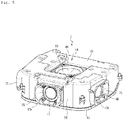
- modular equipment 1 which comprises a generic acoustic enclosure 2.
- module is meant that the equipment 1 comprises, in addition to the acoustic enclosure 2, one or more other distinct additional modules, comprising at least one electronic module, which are integrated with the acoustic enclosure 2 to form the equipment. 1. It is therefore possible, by using different additional modules, to obtain different types of equipment with different functionalities and / or external design , and which all incorporate the same loudspeaker 2.
- acoustic enclosure 2 can be associated with this or these additional module (s) without it being necessary to make any modifications to the acoustic enclosure 2, in order to obtain the different types of equipment.
- the equipment 1 comprises in this case, in addition to the acoustic enclosure 2, a first additional module 3 and a second additional module 4.
- the first additional module 3 corresponds to the upper part of the equipment 1
- the second additional module 4 corresponds to the lower part of the equipment 1
- the loudspeaker 2 is positioned between the first additional module 3 and the second module additional 4.
- the equipment 1 has the general shape of a parallelepiped whose corners are rounded and which has an upper face 5, a lower face 6 and four side faces: a front face 7, a rear face 8, a left face 9 and a right face 10.
- the first additional module 3 comprises a top cover 12 and an additional electronic module which is a digital television decoder 14.
- the top cover 12 forms the top face 5 of the equipment 1. Threaded studs 15 are formed near the corners of the top cover 12 and extend vertically from an inner wall of the top cover 12.
- the first additional module 3 further comprises electronic cards and electronic components which are mounted on the electronic cards and which implement a plurality of functions, and in particular the conventional functions of a digital television decoder: acquisition of audio streams / video, stream processing, etc.
- the electronic components also perform the function of voice recognition and the function of voice assistant with decoding functionality.
- the voice assistant function uses speaker 2.
- the electronic components include in particular connectors 16 making it possible in particular to connect the decoder 14 of the first additional module 3 to a television, to the network, to the sector, etc.
- the electronic components also include microphones for implementing voice recognition, a user interface comprising light displays and buttons, an infrared module which makes it possible to control the equipment 1 using a remote control, etc.
- the electronic boards comprise a main board 17, mounted under the upper cover 12 parallel to the latter and near the internal wall of the upper cover 12, as well as a secondary board 18 positioned at an upper portion of the face. before 7 of the equipment 1.
- the secondary card 18 comprises in particular electronic components for implementing the user interface.
- the second additional module 4 comprises a support plate 20 forming the lower face 6 of the equipment 1 and comprising feet on which the equipment 1 rests when it is placed.
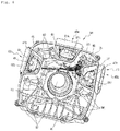
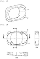
- the acoustic enclosure 2 for its part, firstly comprises a box 23 which also has the general shape of a parallelepiped or a trapezoidal shape, and the corners of which are rounded, and which has an upper face 24, a lower face 25 and four side faces: a front face 26, a rear face 27, a left face 28 and a right face 29 (these faces correspond to the equivalent faces of the equipment 1).
- a front disbursement 30 is formed on the upper part of the front face 26 of the box 23, to integrate the secondary card 18.
- a rear disbursement 31 is formed. on the rear part of the upper face 24 of the box 23, to integrate the connectors 16.
- Tabs 33 each comprising a hole, extend horizontally from the side faces of the box 23 near the corners of the box 23.
- the box 23 comprises a main portion 34 comprising the upper face 24 and the side faces of the box 23, and a lower cover 35 which closes the box 23 and which forms the lower face 25 of the box 23.
- the box 23 is therefore open at the level of its lower face 25 when the lower cover 35 is not positioned on the main portion 34 of the box 23.
- the casing 23 has a groove 36 which extends along the lower surface of its side faces, against which the lower cover 35 is placed to close the casing 23.
- the groove 36 also extends along the lower surface of the casings. internal walls which will be described below.
- the seal between the main portion 34 of the box 23 and the lower cover 35 of the box 23 is provided by a seal 37 deposited in the groove 36.
- the main portion 34 of the box 23 comprises a plurality of threaded studs 38 which extend vertically from a bottom of the main portion 35, that is to say from an internal wall of the upper face 24 of the box 23. Screws 39 extend through the lower cover 35 and are screwed into the threaded studs 38, which allows fix the lower cover 35 to the casing 23 to close the casing 23, and compress the gasket 37 to ensure the seal between the main portion 34 of the casing 23 and the lower cover 35. It is noted that the seal between the main portion 34 of the casing 23 and the lower cover 35 could have been provided by other means, for example by assembling the main portion 34 of the casing 23 and the lower cover 35 by welding or gluing.
- the box 23 further comprises internal partitions 40 which extend vertically from the bottom of the main portion 34, that is to say from the internal wall of the upper face 24 of the box 23.
- the internal partitions 40 define a plurality of sealed acoustic chambers, distinct and separated from each other by said internal partitions 40, each acoustic chamber comprising an orifice opening out towards the outside of the box in a different direction. The sealing between the chambers is ensured by the internal partitions 40 and by the seal 37 deposited in the groove 36 which has just been mentioned.
- the four acoustic chambers include three first acoustic chambers 41 and a second acoustic chamber 42. Each first acoustic chamber 41 occupies a first volume. The second acoustic chamber 42 occupies a second volume greater than each of the first volumes. The second acoustic chamber is a central chamber, that is to say it includes a central portion of the box. The second volume of the second acoustic chamber 42 corresponds to the entire internal volume of the box 23 except for the first volumes of the first acoustic chambers 41.
- Each first acoustic chamber 41 comprises a first orifice 43 which opens outwards at the level of a separate lateral face of the box 23.
- the first three acoustic chambers 41 comprise a first front acoustic chamber 41a comprising a first front orifice 43a opening towards the 'outside at the level of the front face 26 of the box 23, a first left acoustic chamber 41b comprising a first left orifice 43b opening outwards at the level of the left face 28 of the box 23, and a first right acoustic chamber 41c comprising a first straight orifice 43c opening outwards at the level of the right face 29 of the box 23.
- the second acoustic chamber 42 comprises a second orifice 44, positioned in the central portion of the box 23, which opens outwards at the level of a non-lateral face, which is the upper face 24 or the lower face 25 of the box 23.
- the non-lateral face is in this case the upper face 24 of the box 23.
- the second acoustic chamber 42 comprises a third orifice 45 which opens outwards at the level of a face opposite the non-lateral face, that is to say here at the level of the lower face 25 of the box 23.
- the third orifice 45 is made in the lower cover 35 of the box 23.
- the second orifice 44 and the third orifice 45 of the second acoustic chamber 42 are offset with respect to one another along a length or a width of the box 23, here along a length of the box 23 (by "length ”Means the dimension of the box 23 between its front face 26 and its rear face 27).
- the preferred embodiment of the box 23 is plastic injection which makes it possible to obtain shapes complex economically.
- the acoustic enclosure 2 comprises a plurality of loudspeakers each comprising a membrane, each loudspeaker being integrated into one of the acoustic chambers so that the membrane of said loudspeaker extends at the level of an orifice of said orifice. acoustic chamber.
- the enclosure therefore comprises a plurality of first loudspeakers 47 each integrated into a first acoustic chamber 41 of the box 23, as well as a second loudspeaker 48 integrated into the second acoustic chamber 42, and a third integrated loudspeaker 49. himself also in the second acoustic chamber 42.
- the first loudspeakers 47 include a first front loudspeaker 47a integrated in the first front acoustic chamber 41a, a first left loudspeaker 47b integrated in the first left acoustic chamber 41b, and a first right loudspeaker 47c integrated in the first right acoustic chamber 41c.
- the membrane 48 of each first loudspeaker 47 extends at the level of the first orifice 43 of the associated first acoustic chamber 41.
- the first three loudspeakers 47 are identical.
- the second loudspeaker 49 is a bass loudspeaker 49 also called a low frequency loudspeaker, that is to say. say a woofer.
- the third loudspeaker 51 (visible on the figure 1 ) is a passive radiator 51, the membrane 52 of which extends at the level of the third orifice 45 of the second acoustic chamber 42.
- each loudspeaker coincides, or at least extends in the immediate vicinity of the edge of the orifice of the acoustic chamber. associated.
- the interface between the membrane and the orifice is sealed, so that the acoustic chamber is perfectly sealed when the associated loudspeaker is mounted.
- the audio sources requiring a smaller audio volume to operate that is to say the first loudspeakers 47
- the audio sources requiring a smaller audio volume to operate are therefore integrated into the first acoustic chambers 41 and are thus separated from the main volume, that is to say ie the second acoustic chamber 42, by the internal partitions 40, in order to create separate acoustic chambers.
- This configuration makes it possible to avoid interference between the different channels, which would be likely to occur if the different channels shared a common volume of air in the same acoustic chamber.
- the first three loudspeakers 47 are identical, and therefore reproduce the same frequency ranges (unlike a configuration with several loudspeakers in a "conventional" enclosure which reproduce only 'single channel), which makes them particularly susceptible to cross interference.
- the positioning and orientation of the acoustic chambers correspond to an optimization of the acoustics for the customer.
- the left orifice and the right orifice are oriented slightly forward (towards the user), so that these orifices are as close as possible to the outside of the equipment 1, whatever or the design of the equipment 1.
- the first front acoustic chamber 41a corresponds to the central channel.
- the basses occupy the rest of the volume, that is to say the second acoustic chamber 42.
- the second acoustic chamber 42 therefore comprises the bass speaker ( woofer ) 49 and the passive radiator 51.
- the passive radiator 51 makes it possible to reinforce the bass even more.
- the bass speaker 49 opens onto the upper face 24 of the box 23 and the passive radiator on the underside 25 of the box 23.
- the reverse configuration, with the bass speaker 49 opening onto the underside 25 of the box 23 and the passive radiator 51 opening onto the upper face 24 of the box 23, is of course also possible.
- the bass loudspeaker 49 and the passive radiator 51 are therefore in opposition, one upwards and the other downwards. This configuration makes it possible to limit the mechanical pumping effect which could result from the combined presence of the bass speaker 49 and of the passive radiator 51, and therefore to limit the vibrations of the equipment 1.
- the second orifice 44 and the third orifice 45 of the second acoustic chamber 42 are offset with respect to each other along the length of the box 23.
- the position of the passive radiator 51 is therefore not exactly aligned. with that of the subwoofer 49, that is to say that one is not exactly above the other in the box 23.
- This offset makes it possible to limit the height of the box 23 and therefore equipment 1. Indeed, since the passive radiator 51 has both inward and outward travel, if the passive radiator 51 and the woofer 49 were aligned, an additional thickness would be. necessary to allow the movement of the passive radiator 51.
- the use of the passive radiator 51 is optional. When it is decided not to integrate a passive radiator 51 into the equipment 1, the third orifice 45 made in the lower cover 35 of the box 23 is blocked. Two versions of the injection tool of the plastic part constituting the lower cover 35: a first tool for the version without passive radiator 51 and a second tool for the version with passive radiator 51.
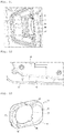
- the second orifice 44 extends to the bottom of a first disbursement 54 formed in an outer wall of the upper face 24 of the box 23.
- the third orifice 45 is positioned at the bottom of a second disbursement 55 formed in an external wall of the lower face 25. This allows the external movement of the membrane 50 of the bass speaker 49 and of the membrane 52 of the passive radiator 51 without them coming into contact with the parts located at the bottom. above and below.
- first disbursement 54 or the second disbursement 55 can be defined between the feet of the equipment 1.
- Such a configuration makes it possible to obtain a design in which at least one of the membranes of the bass speaker 49 and passive radiator 51 is visible from the outside.
- Stiffening ribs 57 are formed in an internal wall of an upper face and / or a lower face of the box, in this case here in the internal wall of the upper face 24 of the box 23.
- the vibrations at low frequencies produced mainly by the bass speaker 49 and the passive radiator 51, can create distortions of the plastic parts forming the box 23, which could result in the loss of the sealing of the acoustic enclosure 2.
- the stiffening ribs 57 make it possible to overcome this problem by stiffening the assembly.
- the stiffening ribs 57 are positioned according to the results of digital simulations of the deformation of the parts using software for the resistance of materials calculated by finite elements.
- the arrangement of the loudspeakers and their integration into the acoustic enclosure 2 makes it possible to obtain a spatialization of the sound, which, coupled with algorithms, makes it possible to obtain an acoustic rendering comparable to that of a more complex and expensive system. .
- the loudspeaker 2 is thus compatible with the DOLBY ATMOS specification.
- the loudspeakers of the acoustic enclosure 2 are electrically connected to the main board 17 of the first additional module 3 (that is to say of the digital television decoder 14).
- a first connector 60 is mounted on the box 23, here on the upper face 24 of the box 23.
- the first connector 60 is a female connector whose contacts are receiving pads 61 intended to cooperate with Pogo pins.
- Pogo pin is understood to mean a pin comprising a spring-loaded piston.
- Electric wires 62 (visible on the figure 6 ), passing through the box 23, connect the loudspeakers to the first connector 60.
- Each of these electric wires 62 has one end connected to a loudspeaker and another end soldered to a reception area 61 of the first connector 60.
- a second connector 63 is mounted on a lower face of the main board 17 of the decoder 14.
- the second connector 63 is a male connector comprising Pogo pins 64.
- the main board 17 of the decoder 14 is mounted on the upper face 24 of the box 23, and the first connector 60 is connected to the second connector 63.
- the Pogo pins 64 of the second connector 63 are thus in contact. with the beaches reception 61 of the first connector 60, which makes it possible to establish an electrical connection between the main board 17 of the decoder 14 and the loudspeakers.
- a gasket 66 is applied over the entire circumference of the first connector 60, so that the first connector 60 is mounted in a sealed manner on the casing 23.
- This solution is very advantageous.
- this solution makes it possible not to use cables to connect the acoustic enclosure 2 to the decoder.
- the use of cables in fact presents several drawbacks. Cables require complicated mounting for assembly. The cables present an increased risk of acoustic leakage at the exit of the cables from the loudspeaker.
- the acoustic enclosure with several first connectors, possibly positioned on different sides of the box, and in particular in the case where the equipment comprises not one but several additional electronic modules.
- the equipment 1 comprises an outer casing 70 which at least partially covers the casing 23.
- the outer casing 70 surrounds and covers the side faces of the casing 23.
- the outer casing 70 is made of a rigid plastic but could be manufactured in any type of material, rigid or not.
- the outer casing 70 is covered with an acoustic fabric.
- the outer casing 70 is itself covered with a decorative outline 73 (visible on the figure 1 ).
- the outer casing 70 comprises sets of at least one hole 71, each set of at least one hole 71 comprising one or more holes, here several holes.
- Each set of holes 71 is intended to be positioned opposite of the membrane of a first loudspeaker 47 when the outer casing 70 is mounted around the side faces of the box 23.
- the sets of holes 71 allow the sounds generated by the first loudspeakers to exit to the outside.
- each first loudspeaker 47 there is in front of each first loudspeaker 47 a set of holes 71.
- the holes of a set of holes 71 are arranged in a honeycomb array, which makes it possible to maximize the number of holes.
- a set of holes 71 while stiffening the outer casing 70 at the level of the set of holes 71.
- the outer casing 70 also comprises a set of holes 71 positioned opposite the rear face 27 of the box 23.
- the sounds produced by the bass speaker 49 are guided between the first additional module 3 and the box 23 towards the rear face 27 of the box 23 and towards the set of holes 71 positioned opposite the rear face 27 of the box 23 Likewise, the sounds produced by the passive radiator 51 are guided between the second additional module 4 and the box 23 towards the rear face 27 of the box 23 and towards the set of holes 71 positioned opposite the rear face 27 of the box. 23.
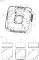
- the outer casing 70 may have a different shape and / or dimensions to give a particular item of equipment its own design.
- a plurality of items of equipment 1a, 1b, 1c which each incorporate an identical acoustic enclosure 2, and the external shape of which is conferred, at least at the level of the lateral faces of the equipment, by the external casing 70.
- the loudspeaker 2, and in particular the box 23, is therefore sized to be compatible with different shapes and dimensions of the equipment 1.
- the contours of the box 23 have therefore been drawn to fit into the smallest design, or one which has the largest radii of curvature.
- Particularly compact equipment 1 can thus be obtained, which integrates the acoustic enclosure 2 comprising the five loudspeakers as well as the decoder 14 in a total volume of less than 200mmx200mmx70mm (whereas a single decoder has a thickness typically close to 25mm) .
- each acoustic horn 75 has a shape and / or dimensions which depend on the shape and / or dimensions of the outer casing 70. It is for example the thickness e of the acoustic horn which depends on the shape and / or dimensions of the outer casing.
- An acoustic horn 75 intended to be mounted between the first left speaker 47b or the first right speaker 47c and the outer casing 70 is described.
- the acoustic horn 75 comprises an upper face 76, a lower face 77, and an internal lateral surface 78 defining a through cavity 79 formed in the thickness e of the horn 75 and having an upper edge 80 defined on the upper face 76 and an edge lower 81 defined on the lower face 77.
- the upper edge 80 has the shape of an ellipse and the lower edge 81 has a circular shape.
- the lower face 77 of the acoustic horn 75 is in contact with the box 23 so that the lower edge 81 of the through cavity 79 surrounds the membrane 48 of the first loudspeaker 47.
- the upper face 76 of the acoustic horn 75 is in contact with the outer casing 70 so that the set of holes 71 of the outer casing 70, positioned opposite the membrane 48 of the first loudspeaker 47, is inside a surface delimited by the upper edge 80 of the through cavity 79. It is possible that the assembly of holes 71, which is inside the surface delimited by the upper edge 80, has only one hole.
- the lower edge 81 of the through cavity 79 is tangent to a circumference of the membrane 48 of the first loudspeaker 47 at any point thereof.
- the internal lateral surface 78 of the acoustic horn 75 guides towards the outside via the set of holes 71 of the external envelope 70 the sounds produced by the first loudspeaker 47.
- the through cavity 79 widens, in a first direction D1, from the lower edge 81 towards the upper edge 80. The widening of the through cavity 79 is greater at the level of the front part than at the level of the rear part. of pavilion 75.
- the through cavity 79 is therefore arranged to guide the sounds in at least one direction, in this case here in the first direction D1.
- the through cavity 79 is also arranged to guide the sounds towards one of the senses of the first direction D1.
- This first direction D1 corresponds to the horizontal direction when the acoustic horn 75 is fixed to the box 23; the direction is forward. The sound is therefore guided in a privileged manner in the horizontal direction and towards the front when the acoustic horn 75 is fixed to the box 23.
- the cavity could be flared so as to guide the sounds in both directions of the same direction, and even in several directions.
- At least a first portion of the internal lateral surface 78, through which the first direction D1 passes, has a hyperbolic shape when viewed in section in a first plane P1 parallel to the thickness e of the acoustic horn 75 and including the first direction D1.
- the shape of the first portions 82 makes it possible to broadcast the sound signals at 180 °.
- At least a second portion 83 of the internal lateral surface 78 through which passes a second direction D2 perpendicular to the first direction D1, has a straight shape and inclined towards the upper edge when seen in section in a second plane P2 parallel to the thickness e of the acoustic horn 75 and including the second direction D2.
- the shape of the second portions 83 makes it possible to guide the sounds as far as the set of holes 71 of the outer casing 70 which is located in front of the first loudspeaker 47.
- Each second portion 83 is inclined at an angle ⁇ between 1 ° and 10 °, here equal to 5 °.
- the thickness e of the acoustic horn 75 is greater in its front part than in its rear part.
- the acoustic horn 75 is therefore not symmetrical along the second plane P2.
- the acoustic horn 75 is however symmetrical with respect to the foreground P1, with the exception of the means for fixing the acoustic horn 75 which here are not symmetrical with respect to said foreground (but which could be).
- keying means are used to avoid assembling the left and right acoustic horns 75 in the wrong direction, which would make it impossible to assemble the acoustic enclosure 2 and the outer casing 70.
- the coding means here comprise coding ribs 85 formed in the box 23, and coding recesses 86 formed on the acoustic horn 75 at the front and at the rear thereof, at two corners of the same length of pavilion 75.
- the coding ribs 85 are located under the first left orifice 43b of the first acoustic chamber left 41b, on either side of said first left orifice 43b.
- the coding ribs 85 are located above the first straight hole 43c of the first right acoustic chamber 41c, on either side of said first straight hole 43c.
- the means of coding could present a different configuration. It is however advantageous that the configuration of the keying means formed on the right face 29 is similar to the configuration of the keying means formed on the left face 28 after the latter has undergone a rotation of 180 °.
- the flag 75 comprises at least one fixing recess 88, in this case two fixing recesses 88, which are each made in the internal lateral surface 78 to open out at the upper face 76 of the flag 75.
- the two fixing recesses 88 are diametrically opposed with respect to the lower circular edge 81 of the through cavity 79.
- the flag 75 further comprises at least one cover recess 89, in this case two cover recesses 89 opening out at the level of the lower face 77.
- the two cover recesses 89 are diametrically opposed. relative to the lower edge 81 of the through cavity 79.
- the two fixing recesses 88 and the two cover recesses 89 are each positioned on the corners of a virtual rectangle (which may be a square) within which s' extends the lower edge 81.
- the cover recesses 89 are each intended to cover a head of a first screw 91 used to fix (only) the loudspeaker to the box.
- the fixing recesses 88 are each intended to accommodate a head of a second screw 90 used to fix the acoustic horn and the loudspeaker to the box.
- the fixing of the first loudspeaker 47 and the horn 75 is carried out as follows.
- the first loudspeaker 47 is positioned on the box 23.
- Two first screws 91 are first of all used to fix the first loudspeaker 47 to the box 23.
- the horn 75 is then placed against the box 23.
- the two recesses of cover 89 cover the first two screws 91.
- Two second screws 90 are then used to fix both the acoustic horn 75 and the first speaker 47 to the box 23.
- the two second screws 90 each extend into one of the fixing recesses 88, which each receive the screw head of one of the second screws 90 when the first loudspeaker 47 and the acoustic horn 75 are fixed to the box 23.
- the fixing solution which has just been described has the following advantages. If the acoustic horn 75 were fixed by the four screws with which the first loudspeaker 47 is fixed, it would have been difficult to disassemble the acoustic horn 75 after the complete assembly of the equipment 1 without dropping the first loudspeaker. 47 inside the box 23. Each first loudspeaker 47 is therefore fixed only by the first two screws 91 initially, to then allow the acoustic horn 75 to be screwed using the two second remaining screws 90. The first two screws 91 which initially hold the first loudspeaker 47 are embedded under the acoustic horn 75 (by being positioned in the cover recesses 89).
- a visual indicator 94 present on the box 23, shows the location of the first two screws 91 to be screwed in first.
- additional sealing pieces can optionally be inserted into the fixing recesses 88 allowing screwing.
- each of the fixing recesses 88 of the acoustic horn 75 at least one guide notch which will help the correct alignment with the plugging part.
- the plugging part then comprises a guide (or vice versa, the notch possibly being on the plugging part and the guide on the flag 75).
- the surface of the flag 75 having a different shape at the level of the two fixing recesses 88, two different shapes of plugging parts are provided to adapt to the shape of the flag 75. It will therefore be advantageous to provide two notches / guides for each. plugging part, the notches / guides not being placed at 180 ° but at different angles for the two fixing recesses, which prevents the insertion of a plugging part in the fixing recess 88 to which it does not is not intended.
- the acoustic horn 75 can be made of more or less rigid plastic.
- the acoustic horn 75 can also be made of rubber to optimize the acoustic and vibratory behavior.
- the horn 75 then comprises a deformable lip 93 which on the one hand ensures the acoustic sealing between the outlet of the first loudspeaker 47 and the ambient medium, and which on the other hand dampens any vibrations of the outer casing 70.
- This configuration requires the creation of pavilions specific for each design of the equipment, the outline of which is different, in order to come back to the optimum on the outer casing.
- the roof 75 includes both a rigid portion, made for example of rigid plastic, and a flexible portion at the interface with the outer casing, made for example of rubber.
- a flag in two distinct pieces superimposed in the thickness of the flag: a first piece, thinner, which is made of rigid plastic, and a second, thicker piece, which is made of rubber.
- the first part is a generic part while the second part depends on the shape and / or dimensions of the outer shell.
- the first part and the second part can optionally be fixed by the same screws, the first part being sandwiched between the acoustic box and the second part.
Landscapes
- Physics & Mathematics (AREA)
- Engineering & Computer Science (AREA)
- Acoustics & Sound (AREA)
- Signal Processing (AREA)
- Health & Medical Sciences (AREA)
- Otolaryngology (AREA)
- Details Of Audible-Bandwidth Transducers (AREA)
Priority Applications (1)
| Application Number | Priority Date | Filing Date | Title |
|---|---|---|---|
| EP23185358.1A EP4250766B1 (de) | 2020-05-25 | 2021-05-21 | Allgemeine lautsprecherbox |
Applications Claiming Priority (1)
| Application Number | Priority Date | Filing Date | Title |
|---|---|---|---|
| FR2005499A FR3110799B1 (fr) | 2020-05-25 | 2020-05-25 | Enceinte acoustique générique |
Related Child Applications (2)
| Application Number | Title | Priority Date | Filing Date |
|---|---|---|---|
| EP23185358.1A Division-Into EP4250766B1 (de) | 2020-05-25 | 2021-05-21 | Allgemeine lautsprecherbox |
| EP23185358.1A Division EP4250766B1 (de) | 2020-05-25 | 2021-05-21 | Allgemeine lautsprecherbox |
Publications (2)
| Publication Number | Publication Date |
|---|---|
| EP3917153A1 true EP3917153A1 (de) | 2021-12-01 |
| EP3917153B1 EP3917153B1 (de) | 2023-08-23 |
Family
ID=72356121
Family Applications (2)
| Application Number | Title | Priority Date | Filing Date |
|---|---|---|---|
| EP21175450.2A Active EP3917153B1 (de) | 2020-05-25 | 2021-05-21 | Allgemeine lautsprecherbox |
| EP23185358.1A Active EP4250766B1 (de) | 2020-05-25 | 2021-05-21 | Allgemeine lautsprecherbox |
Family Applications After (1)
| Application Number | Title | Priority Date | Filing Date |
|---|---|---|---|
| EP23185358.1A Active EP4250766B1 (de) | 2020-05-25 | 2021-05-21 | Allgemeine lautsprecherbox |
Country Status (6)
| Country | Link |
|---|---|
| US (1) | US11843911B2 (de) |
| EP (2) | EP3917153B1 (de) |
| CN (1) | CN113727224A (de) |
| ES (1) | ES3045367T3 (de) |
| FR (1) | FR3110799B1 (de) |
| PT (1) | PT4250766T (de) |
Families Citing this family (5)
| Publication number | Priority date | Publication date | Assignee | Title |
|---|---|---|---|---|
| DE202019102830U1 (de) * | 2019-05-20 | 2019-06-25 | Häfele Berlin Gmbh & Co Kg | Kunststoff-Möbelwandteil |
| FR3139405A1 (fr) * | 2022-12-06 | 2024-03-08 | Sagemcom Broadband Sas | Equipement comportant un caisson acoustique doté d’au moins un amplificateur |
| FR3147897B1 (fr) * | 2023-04-17 | 2025-05-30 | Sagemcom Broadband Sas | Enceinte acoustique de hauteur réduite |
| USD1079669S1 (en) * | 2023-09-11 | 2025-06-17 | Haipeng Chen | Speakerphone |
| US20250211883A1 (en) * | 2023-12-22 | 2025-06-26 | Sagemcom Broadband Sas | Connector maximising the available technical volume |
Citations (7)
| Publication number | Priority date | Publication date | Assignee | Title |
|---|---|---|---|---|
| US4168762A (en) * | 1978-01-13 | 1979-09-25 | Amanita Sound, Inc. | Loudspeaker enclosure |
| US20120014544A1 (en) * | 2010-06-16 | 2012-01-19 | Gladwin Timothy | Bipolar speaker with improved clarity |
| US8175304B1 (en) * | 2008-02-12 | 2012-05-08 | North Donald J | Compact loudspeaker system |
| CN206024070U (zh) * | 2016-07-20 | 2017-03-15 | 张文川 | 全角度高保真立体声音箱 |
| US20170280231A1 (en) * | 2014-09-30 | 2017-09-28 | Apple Inc. | Loudspeaker with reduced audio coloration caused by reflections from a surface |
| US20180091897A1 (en) * | 2016-09-23 | 2018-03-29 | Apple Inc. | Audio driver and power supply unit architecture |
| CN207427379U (zh) * | 2017-09-26 | 2018-05-29 | 歌尔科技有限公司 | 一种可拆卸音箱的连接结构 |
Family Cites Families (7)
| Publication number | Priority date | Publication date | Assignee | Title |
|---|---|---|---|---|
| DE3128462C2 (de) * | 1981-07-18 | 1983-07-07 | Standard Elektrik Lorenz Ag, 7000 Stuttgart | Fernsehempfangsgerät für stereophone Tonwiedergabe |
| US4624337A (en) * | 1985-10-02 | 1986-11-25 | Shavers Glynn S | Speaker enclosure |
| US6381335B2 (en) * | 1999-08-25 | 2002-04-30 | Gibson Guitar Corp. | Audio speaker system for personal computer |
| US9866961B2 (en) * | 2004-12-01 | 2018-01-09 | Todd Beauchamp | Multi-channel loudspeaker enclosure with laterally projecting wings and method for orienting and driving multiple loudspeakers |
| US20110111643A1 (en) * | 2009-11-07 | 2011-05-12 | Yin Te-Hung | Audio Connector |
| US9883265B2 (en) * | 2015-01-05 | 2018-01-30 | Braven, Lc | Wireless speaker and system |
| US11640108B1 (en) * | 2020-04-06 | 2023-05-02 | Amazon Technologies, Inc. | Sealed speaker and speaker back volume without wires |
-
2020
- 2020-05-25 FR FR2005499A patent/FR3110799B1/fr not_active Expired - Fee Related
-
2021
- 2021-05-21 EP EP21175450.2A patent/EP3917153B1/de active Active
- 2021-05-21 PT PT231853581T patent/PT4250766T/pt unknown
- 2021-05-21 ES ES23185358T patent/ES3045367T3/es active Active
- 2021-05-21 EP EP23185358.1A patent/EP4250766B1/de active Active
- 2021-05-25 CN CN202110571665.8A patent/CN113727224A/zh active Pending
- 2021-05-25 US US17/329,726 patent/US11843911B2/en active Active
Patent Citations (7)
| Publication number | Priority date | Publication date | Assignee | Title |
|---|---|---|---|---|
| US4168762A (en) * | 1978-01-13 | 1979-09-25 | Amanita Sound, Inc. | Loudspeaker enclosure |
| US8175304B1 (en) * | 2008-02-12 | 2012-05-08 | North Donald J | Compact loudspeaker system |
| US20120014544A1 (en) * | 2010-06-16 | 2012-01-19 | Gladwin Timothy | Bipolar speaker with improved clarity |
| US20170280231A1 (en) * | 2014-09-30 | 2017-09-28 | Apple Inc. | Loudspeaker with reduced audio coloration caused by reflections from a surface |
| CN206024070U (zh) * | 2016-07-20 | 2017-03-15 | 张文川 | 全角度高保真立体声音箱 |
| US20180091897A1 (en) * | 2016-09-23 | 2018-03-29 | Apple Inc. | Audio driver and power supply unit architecture |
| CN207427379U (zh) * | 2017-09-26 | 2018-05-29 | 歌尔科技有限公司 | 一种可拆卸音箱的连接结构 |
Also Published As
| Publication number | Publication date |
|---|---|
| CN113727224A (zh) | 2021-11-30 |
| ES3045367T3 (en) | 2025-11-28 |
| US11843911B2 (en) | 2023-12-12 |
| PT4250766T (pt) | 2025-10-23 |
| US20210368261A1 (en) | 2021-11-25 |
| EP3917153B1 (de) | 2023-08-23 |
| EP4250766A3 (de) | 2023-11-15 |
| EP4250766B1 (de) | 2025-07-23 |
| FR3110799B1 (fr) | 2023-06-23 |
| FR3110799A1 (fr) | 2021-11-26 |
| EP4250766A2 (de) | 2023-09-27 |
Similar Documents
| Publication | Publication Date | Title |
|---|---|---|
| EP3917159B1 (de) | Schalltrichter für allgemeine lautsprecherbox | |
| EP3917153B1 (de) | Allgemeine lautsprecherbox | |
| FR2538985A1 (fr) | Agencement de haut-parleurs a une ou plusieurs membranes plates | |
| CN101600142B (zh) | 电子装置的音箱结构 | |
| EP2172057A1 (de) | Klangwiedergabesystem mit einem lautsprechergehäuse mit anschlüssen sowie entsprechende verarbeitungsschaltung | |
| BE1029479B1 (fr) | Sous–système de protection contre les infiltrions pour les microphones dans les appareils informatiques mobile | |
| FR2631195A1 (fr) | Installation sonore, en particulier stereophonique pour televiseurs a haut-parleur integre de frequences basses de grandes dimensions | |
| EP2870032B1 (de) | Lautsprechersystem für ein kraftfahrzeug | |
| FR2499346A1 (fr) | Systeme de reproduction electro-acoustique a effet reflex | |
| EP4029288A1 (de) | Vorrichtung zur schalldiffusion mit kontrollierter breitbandrichtcharakteristik | |
| EP4478699A1 (de) | Kamera-einsatzmodul mit vertikaler montage | |
| EP4451700B1 (de) | Dekodergehäuse mit reduzierter höhe | |
| EP4383748A1 (de) | Ausrüstung mit einem akustischen gehäuse mit mindestens einem verstärker | |
| FR3157765A1 (fr) | Enceinte compacte à conception externe modulaire | |
| FR3065135A1 (fr) | Enceinte acoustique | |
| FR2545302A1 (fr) | Filtre acoustique pour transducteur en particulier du type electromagnetique de combine telephonique | |
| FR3087987A1 (fr) | Dispositif de stereophonie elargie pour enceintes acoustiques monobloc amplifiees | |
| EP3637787A1 (de) | Lautsprecherbox, die ein gehäuse aus monoblock-kunststoffmaterial umfasst | |
| EP4336860B1 (de) | Wärmesenke-entlüftung | |
| FR2924523A1 (fr) | Etui pour microphone unidirectionnel et appareil electronique comportant un tel etui | |
| WO1999034641A1 (fr) | Tunnel acoustique | |
| EP4416934A1 (de) | Zirkumaurales oder supra-aurales ohrstück eines audio-kopfhörers und zugehöriges montageverfahren | |
| EP4664923A1 (de) | Akustische horn für gehäuse mit gekrümmten oberflächen | |
| FR2652978A1 (fr) | Enceinte acoustique. | |
| FR3128086A1 (fr) | Oreillette circum-auriculaire ou supra auriculaire d’un casqur audio et procede de montage associe |
Legal Events
| Date | Code | Title | Description |
|---|---|---|---|
| PUAI | Public reference made under article 153(3) epc to a published international application that has entered the european phase |
Free format text: ORIGINAL CODE: 0009012 |
|
| STAA | Information on the status of an ep patent application or granted ep patent |
Free format text: STATUS: EXAMINATION IS IN PROGRESS |
|
| 17P | Request for examination filed |
Effective date: 20210521 |
|
| AK | Designated contracting states |
Kind code of ref document: A1 Designated state(s): AL AT BE BG CH CY CZ DE DK EE ES FI FR GB GR HR HU IE IS IT LI LT LU LV MC MK MT NL NO PL PT RO RS SE SI SK SM TR |
|
| B565 | Issuance of search results under rule 164(2) epc |
Effective date: 20211014 |
|
| GRAP | Despatch of communication of intention to grant a patent |
Free format text: ORIGINAL CODE: EPIDOSNIGR1 |
|
| STAA | Information on the status of an ep patent application or granted ep patent |
Free format text: STATUS: GRANT OF PATENT IS INTENDED |
|
| RIC1 | Information provided on ipc code assigned before grant |
Ipc: H04R 1/28 20060101ALN20221006BHEP Ipc: H04R 1/26 20060101ALI20221006BHEP Ipc: H04R 5/02 20060101ALI20221006BHEP Ipc: H04R 1/30 20060101ALI20221006BHEP Ipc: H04R 1/02 20060101AFI20221006BHEP |
|
| INTG | Intention to grant announced |
Effective date: 20221021 |
|
| GRAJ | Information related to disapproval of communication of intention to grant by the applicant or resumption of examination proceedings by the epo deleted |
Free format text: ORIGINAL CODE: EPIDOSDIGR1 |
|
| STAA | Information on the status of an ep patent application or granted ep patent |
Free format text: STATUS: EXAMINATION IS IN PROGRESS |
|
| GRAP | Despatch of communication of intention to grant a patent |
Free format text: ORIGINAL CODE: EPIDOSNIGR1 |
|
| STAA | Information on the status of an ep patent application or granted ep patent |
Free format text: STATUS: GRANT OF PATENT IS INTENDED |
|
| INTC | Intention to grant announced (deleted) | ||
| RIC1 | Information provided on ipc code assigned before grant |
Ipc: H04R 1/28 20060101ALN20230228BHEP Ipc: H04R 1/26 20060101ALI20230228BHEP Ipc: H04R 5/02 20060101ALI20230228BHEP Ipc: H04R 1/30 20060101ALI20230228BHEP Ipc: H04R 1/02 20060101AFI20230228BHEP |
|
| INTG | Intention to grant announced |
Effective date: 20230315 |
|
| GRAS | Grant fee paid |
Free format text: ORIGINAL CODE: EPIDOSNIGR3 |
|
| GRAA | (expected) grant |
Free format text: ORIGINAL CODE: 0009210 |
|
| STAA | Information on the status of an ep patent application or granted ep patent |
Free format text: STATUS: THE PATENT HAS BEEN GRANTED |
|
| AK | Designated contracting states |
Kind code of ref document: B1 Designated state(s): AL AT BE BG CH CY CZ DE DK EE ES FI FR GB GR HR HU IE IS IT LI LT LU LV MC MK MT NL NO PL PT RO RS SE SI SK SM TR |
|
| REG | Reference to a national code |
Ref country code: GB Ref legal event code: FG4D Free format text: NOT ENGLISH |
|
| REG | Reference to a national code |
Ref country code: CH Ref legal event code: EP |
|
| REG | Reference to a national code |
Ref country code: DE Ref legal event code: R096 Ref document number: 602021004442 Country of ref document: DE |
|
| REG | Reference to a national code |
Ref country code: IE Ref legal event code: FG4D Free format text: LANGUAGE OF EP DOCUMENT: FRENCH |
|
| REG | Reference to a national code |
Ref country code: LT Ref legal event code: MG9D |
|
| RAP4 | Party data changed (patent owner data changed or rights of a patent transferred) |
Owner name: SAGEMCOM BROADBAND SAS |
|
| REG | Reference to a national code |
Ref country code: NL Ref legal event code: MP Effective date: 20230823 |
|
| REG | Reference to a national code |
Ref country code: AT Ref legal event code: MK05 Ref document number: 1603963 Country of ref document: AT Kind code of ref document: T Effective date: 20230823 |
|
| PG25 | Lapsed in a contracting state [announced via postgrant information from national office to epo] |
Ref country code: GR Free format text: LAPSE BECAUSE OF FAILURE TO SUBMIT A TRANSLATION OF THE DESCRIPTION OR TO PAY THE FEE WITHIN THE PRESCRIBED TIME-LIMIT Effective date: 20231124 |
|
| PG25 | Lapsed in a contracting state [announced via postgrant information from national office to epo] |
Ref country code: IS Free format text: LAPSE BECAUSE OF FAILURE TO SUBMIT A TRANSLATION OF THE DESCRIPTION OR TO PAY THE FEE WITHIN THE PRESCRIBED TIME-LIMIT Effective date: 20231223 |
|
| PG25 | Lapsed in a contracting state [announced via postgrant information from national office to epo] |
Ref country code: SE Free format text: LAPSE BECAUSE OF FAILURE TO SUBMIT A TRANSLATION OF THE DESCRIPTION OR TO PAY THE FEE WITHIN THE PRESCRIBED TIME-LIMIT Effective date: 20230823 Ref country code: RS Free format text: LAPSE BECAUSE OF FAILURE TO SUBMIT A TRANSLATION OF THE DESCRIPTION OR TO PAY THE FEE WITHIN THE PRESCRIBED TIME-LIMIT Effective date: 20230823 Ref country code: PT Free format text: LAPSE BECAUSE OF FAILURE TO SUBMIT A TRANSLATION OF THE DESCRIPTION OR TO PAY THE FEE WITHIN THE PRESCRIBED TIME-LIMIT Effective date: 20231226 Ref country code: NO Free format text: LAPSE BECAUSE OF FAILURE TO SUBMIT A TRANSLATION OF THE DESCRIPTION OR TO PAY THE FEE WITHIN THE PRESCRIBED TIME-LIMIT Effective date: 20231123 Ref country code: NL Free format text: LAPSE BECAUSE OF FAILURE TO SUBMIT A TRANSLATION OF THE DESCRIPTION OR TO PAY THE FEE WITHIN THE PRESCRIBED TIME-LIMIT Effective date: 20230823 Ref country code: LV Free format text: LAPSE BECAUSE OF FAILURE TO SUBMIT A TRANSLATION OF THE DESCRIPTION OR TO PAY THE FEE WITHIN THE PRESCRIBED TIME-LIMIT Effective date: 20230823 Ref country code: LT Free format text: LAPSE BECAUSE OF FAILURE TO SUBMIT A TRANSLATION OF THE DESCRIPTION OR TO PAY THE FEE WITHIN THE PRESCRIBED TIME-LIMIT Effective date: 20230823 Ref country code: IS Free format text: LAPSE BECAUSE OF FAILURE TO SUBMIT A TRANSLATION OF THE DESCRIPTION OR TO PAY THE FEE WITHIN THE PRESCRIBED TIME-LIMIT Effective date: 20231223 Ref country code: HR Free format text: LAPSE BECAUSE OF FAILURE TO SUBMIT A TRANSLATION OF THE DESCRIPTION OR TO PAY THE FEE WITHIN THE PRESCRIBED TIME-LIMIT Effective date: 20230823 Ref country code: GR Free format text: LAPSE BECAUSE OF FAILURE TO SUBMIT A TRANSLATION OF THE DESCRIPTION OR TO PAY THE FEE WITHIN THE PRESCRIBED TIME-LIMIT Effective date: 20231124 Ref country code: FI Free format text: LAPSE BECAUSE OF FAILURE TO SUBMIT A TRANSLATION OF THE DESCRIPTION OR TO PAY THE FEE WITHIN THE PRESCRIBED TIME-LIMIT Effective date: 20230823 Ref country code: AT Free format text: LAPSE BECAUSE OF FAILURE TO SUBMIT A TRANSLATION OF THE DESCRIPTION OR TO PAY THE FEE WITHIN THE PRESCRIBED TIME-LIMIT Effective date: 20230823 |
|
| PG25 | Lapsed in a contracting state [announced via postgrant information from national office to epo] |
Ref country code: PL Free format text: LAPSE BECAUSE OF FAILURE TO SUBMIT A TRANSLATION OF THE DESCRIPTION OR TO PAY THE FEE WITHIN THE PRESCRIBED TIME-LIMIT Effective date: 20230823 |
|
| PG25 | Lapsed in a contracting state [announced via postgrant information from national office to epo] |
Ref country code: ES Free format text: LAPSE BECAUSE OF FAILURE TO SUBMIT A TRANSLATION OF THE DESCRIPTION OR TO PAY THE FEE WITHIN THE PRESCRIBED TIME-LIMIT Effective date: 20230823 |
|
| PG25 | Lapsed in a contracting state [announced via postgrant information from national office to epo] |
Ref country code: SM Free format text: LAPSE BECAUSE OF FAILURE TO SUBMIT A TRANSLATION OF THE DESCRIPTION OR TO PAY THE FEE WITHIN THE PRESCRIBED TIME-LIMIT Effective date: 20230823 Ref country code: RO Free format text: LAPSE BECAUSE OF FAILURE TO SUBMIT A TRANSLATION OF THE DESCRIPTION OR TO PAY THE FEE WITHIN THE PRESCRIBED TIME-LIMIT Effective date: 20230823 Ref country code: ES Free format text: LAPSE BECAUSE OF FAILURE TO SUBMIT A TRANSLATION OF THE DESCRIPTION OR TO PAY THE FEE WITHIN THE PRESCRIBED TIME-LIMIT Effective date: 20230823 Ref country code: EE Free format text: LAPSE BECAUSE OF FAILURE TO SUBMIT A TRANSLATION OF THE DESCRIPTION OR TO PAY THE FEE WITHIN THE PRESCRIBED TIME-LIMIT Effective date: 20230823 Ref country code: DK Free format text: LAPSE BECAUSE OF FAILURE TO SUBMIT A TRANSLATION OF THE DESCRIPTION OR TO PAY THE FEE WITHIN THE PRESCRIBED TIME-LIMIT Effective date: 20230823 Ref country code: CZ Free format text: LAPSE BECAUSE OF FAILURE TO SUBMIT A TRANSLATION OF THE DESCRIPTION OR TO PAY THE FEE WITHIN THE PRESCRIBED TIME-LIMIT Effective date: 20230823 Ref country code: SK Free format text: LAPSE BECAUSE OF FAILURE TO SUBMIT A TRANSLATION OF THE DESCRIPTION OR TO PAY THE FEE WITHIN THE PRESCRIBED TIME-LIMIT Effective date: 20230823 |
|
| REG | Reference to a national code |
Ref country code: DE Ref legal event code: R097 Ref document number: 602021004442 Country of ref document: DE |
|
| PG25 | Lapsed in a contracting state [announced via postgrant information from national office to epo] |
Ref country code: IT Free format text: LAPSE BECAUSE OF FAILURE TO SUBMIT A TRANSLATION OF THE DESCRIPTION OR TO PAY THE FEE WITHIN THE PRESCRIBED TIME-LIMIT Effective date: 20230823 |
|
| PLBE | No opposition filed within time limit |
Free format text: ORIGINAL CODE: 0009261 |
|
| STAA | Information on the status of an ep patent application or granted ep patent |
Free format text: STATUS: NO OPPOSITION FILED WITHIN TIME LIMIT |
|
| 26N | No opposition filed |
Effective date: 20240524 |
|
| PG25 | Lapsed in a contracting state [announced via postgrant information from national office to epo] |
Ref country code: SI Free format text: LAPSE BECAUSE OF FAILURE TO SUBMIT A TRANSLATION OF THE DESCRIPTION OR TO PAY THE FEE WITHIN THE PRESCRIBED TIME-LIMIT Effective date: 20230823 |
|
| PG25 | Lapsed in a contracting state [announced via postgrant information from national office to epo] |
Ref country code: BG Free format text: LAPSE BECAUSE OF FAILURE TO SUBMIT A TRANSLATION OF THE DESCRIPTION OR TO PAY THE FEE WITHIN THE PRESCRIBED TIME-LIMIT Effective date: 20230823 |
|
| PG25 | Lapsed in a contracting state [announced via postgrant information from national office to epo] |
Ref country code: BG Free format text: LAPSE BECAUSE OF FAILURE TO SUBMIT A TRANSLATION OF THE DESCRIPTION OR TO PAY THE FEE WITHIN THE PRESCRIBED TIME-LIMIT Effective date: 20230823 |
|
| REG | Reference to a national code |
Ref country code: CH Ref legal event code: PL |
|
| PG25 | Lapsed in a contracting state [announced via postgrant information from national office to epo] |
Ref country code: MC Free format text: LAPSE BECAUSE OF FAILURE TO SUBMIT A TRANSLATION OF THE DESCRIPTION OR TO PAY THE FEE WITHIN THE PRESCRIBED TIME-LIMIT Effective date: 20230823 |
|
| PG25 | Lapsed in a contracting state [announced via postgrant information from national office to epo] |
Ref country code: LU Free format text: LAPSE BECAUSE OF NON-PAYMENT OF DUE FEES Effective date: 20240521 |
|
| PG25 | Lapsed in a contracting state [announced via postgrant information from national office to epo] |
Ref country code: MC Free format text: LAPSE BECAUSE OF FAILURE TO SUBMIT A TRANSLATION OF THE DESCRIPTION OR TO PAY THE FEE WITHIN THE PRESCRIBED TIME-LIMIT Effective date: 20230823 Ref country code: LU Free format text: LAPSE BECAUSE OF NON-PAYMENT OF DUE FEES Effective date: 20240521 Ref country code: CH Free format text: LAPSE BECAUSE OF NON-PAYMENT OF DUE FEES Effective date: 20240531 |
|
| REG | Reference to a national code |
Ref country code: BE Ref legal event code: MM Effective date: 20240531 |
|
| PG25 | Lapsed in a contracting state [announced via postgrant information from national office to epo] |
Ref country code: IE Free format text: LAPSE BECAUSE OF NON-PAYMENT OF DUE FEES Effective date: 20240521 |
|
| PG25 | Lapsed in a contracting state [announced via postgrant information from national office to epo] |
Ref country code: BE Free format text: LAPSE BECAUSE OF NON-PAYMENT OF DUE FEES Effective date: 20240531 |
|
| PGFP | Annual fee paid to national office [announced via postgrant information from national office to epo] |
Ref country code: DE Payment date: 20250423 Year of fee payment: 5 |
|
| PGFP | Annual fee paid to national office [announced via postgrant information from national office to epo] |
Ref country code: GB Payment date: 20250423 Year of fee payment: 5 |
|
| PGFP | Annual fee paid to national office [announced via postgrant information from national office to epo] |
Ref country code: FR Payment date: 20250424 Year of fee payment: 5 |
|
| PG25 | Lapsed in a contracting state [announced via postgrant information from national office to epo] |
Ref country code: CY Free format text: LAPSE BECAUSE OF FAILURE TO SUBMIT A TRANSLATION OF THE DESCRIPTION OR TO PAY THE FEE WITHIN THE PRESCRIBED TIME-LIMIT; INVALID AB INITIO Effective date: 20210521 |
|
| PG25 | Lapsed in a contracting state [announced via postgrant information from national office to epo] |
Ref country code: HU Free format text: LAPSE BECAUSE OF FAILURE TO SUBMIT A TRANSLATION OF THE DESCRIPTION OR TO PAY THE FEE WITHIN THE PRESCRIBED TIME-LIMIT; INVALID AB INITIO Effective date: 20210521 |