EP3916894A1 - Lower box body, battery pack and vehicle - Google Patents
Lower box body, battery pack and vehicle Download PDFInfo
- Publication number
- EP3916894A1 EP3916894A1 EP20865202.4A EP20865202A EP3916894A1 EP 3916894 A1 EP3916894 A1 EP 3916894A1 EP 20865202 A EP20865202 A EP 20865202A EP 3916894 A1 EP3916894 A1 EP 3916894A1
- Authority
- EP
- European Patent Office
- Prior art keywords
- box body
- lower box
- exhaust
- accommodating area
- baffle
- Prior art date
- Legal status (The legal status is an assumption and is not a legal conclusion. Google has not performed a legal analysis and makes no representation as to the accuracy of the status listed.)
- Pending
Links
- 238000004891 communication Methods 0.000 claims abstract description 4
- 238000009423 ventilation Methods 0.000 claims description 52
- 238000007789 sealing Methods 0.000 claims description 7
- 238000010586 diagram Methods 0.000 description 18
- 238000013461 design Methods 0.000 description 10
- 239000000428 dust Substances 0.000 description 3
- 238000002844 melting Methods 0.000 description 3
- 230000008018 melting Effects 0.000 description 3
- 238000012986 modification Methods 0.000 description 2
- 230000004048 modification Effects 0.000 description 2
- 230000009286 beneficial effect Effects 0.000 description 1
- 238000011982 device technology Methods 0.000 description 1
- 238000009792 diffusion process Methods 0.000 description 1
- 238000004146 energy storage Methods 0.000 description 1
- 239000012535 impurity Substances 0.000 description 1
- 238000000034 method Methods 0.000 description 1
- 238000003466 welding Methods 0.000 description 1
Images


Classifications
-
- B—PERFORMING OPERATIONS; TRANSPORTING
- B60—VEHICLES IN GENERAL
- B60L—PROPULSION OF ELECTRICALLY-PROPELLED VEHICLES; SUPPLYING ELECTRIC POWER FOR AUXILIARY EQUIPMENT OF ELECTRICALLY-PROPELLED VEHICLES; ELECTRODYNAMIC BRAKE SYSTEMS FOR VEHICLES IN GENERAL; MAGNETIC SUSPENSION OR LEVITATION FOR VEHICLES; MONITORING OPERATING VARIABLES OF ELECTRICALLY-PROPELLED VEHICLES; ELECTRIC SAFETY DEVICES FOR ELECTRICALLY-PROPELLED VEHICLES
- B60L50/00—Electric propulsion with power supplied within the vehicle
- B60L50/50—Electric propulsion with power supplied within the vehicle using propulsion power supplied by batteries or fuel cells
- B60L50/60—Electric propulsion with power supplied within the vehicle using propulsion power supplied by batteries or fuel cells using power supplied by batteries
- B60L50/66—Arrangements of batteries
-
- B—PERFORMING OPERATIONS; TRANSPORTING
- B60—VEHICLES IN GENERAL
- B60K—ARRANGEMENT OR MOUNTING OF PROPULSION UNITS OR OF TRANSMISSIONS IN VEHICLES; ARRANGEMENT OR MOUNTING OF PLURAL DIVERSE PRIME-MOVERS IN VEHICLES; AUXILIARY DRIVES FOR VEHICLES; INSTRUMENTATION OR DASHBOARDS FOR VEHICLES; ARRANGEMENTS IN CONNECTION WITH COOLING, AIR INTAKE, GAS EXHAUST OR FUEL SUPPLY OF PROPULSION UNITS IN VEHICLES
- B60K1/00—Arrangement or mounting of electrical propulsion units
- B60K1/04—Arrangement or mounting of electrical propulsion units of the electric storage means for propulsion
-
- H—ELECTRICITY
- H01—ELECTRIC ELEMENTS
- H01M—PROCESSES OR MEANS, e.g. BATTERIES, FOR THE DIRECT CONVERSION OF CHEMICAL ENERGY INTO ELECTRICAL ENERGY
- H01M50/00—Constructional details or processes of manufacture of the non-active parts of electrochemical cells other than fuel cells, e.g. hybrid cells
- H01M50/20—Mountings; Secondary casings or frames; Racks, modules or packs; Suspension devices; Shock absorbers; Transport or carrying devices; Holders
- H01M50/204—Racks, modules or packs for multiple batteries or multiple cells
-
- H—ELECTRICITY
- H01—ELECTRIC ELEMENTS
- H01M—PROCESSES OR MEANS, e.g. BATTERIES, FOR THE DIRECT CONVERSION OF CHEMICAL ENERGY INTO ELECTRICAL ENERGY
- H01M50/00—Constructional details or processes of manufacture of the non-active parts of electrochemical cells other than fuel cells, e.g. hybrid cells
- H01M50/20—Mountings; Secondary casings or frames; Racks, modules or packs; Suspension devices; Shock absorbers; Transport or carrying devices; Holders
- H01M50/233—Mountings; Secondary casings or frames; Racks, modules or packs; Suspension devices; Shock absorbers; Transport or carrying devices; Holders characterised by physical properties of casings or racks, e.g. dimensions
-
- H—ELECTRICITY
- H01—ELECTRIC ELEMENTS
- H01M—PROCESSES OR MEANS, e.g. BATTERIES, FOR THE DIRECT CONVERSION OF CHEMICAL ENERGY INTO ELECTRICAL ENERGY
- H01M50/00—Constructional details or processes of manufacture of the non-active parts of electrochemical cells other than fuel cells, e.g. hybrid cells
- H01M50/20—Mountings; Secondary casings or frames; Racks, modules or packs; Suspension devices; Shock absorbers; Transport or carrying devices; Holders
- H01M50/249—Mountings; Secondary casings or frames; Racks, modules or packs; Suspension devices; Shock absorbers; Transport or carrying devices; Holders specially adapted for aircraft or vehicles, e.g. cars or trains
-
- H—ELECTRICITY
- H01—ELECTRIC ELEMENTS
- H01M—PROCESSES OR MEANS, e.g. BATTERIES, FOR THE DIRECT CONVERSION OF CHEMICAL ENERGY INTO ELECTRICAL ENERGY
- H01M50/00—Constructional details or processes of manufacture of the non-active parts of electrochemical cells other than fuel cells, e.g. hybrid cells
- H01M50/30—Arrangements for facilitating escape of gases
- H01M50/317—Re-sealable arrangements
-
- H—ELECTRICITY
- H01—ELECTRIC ELEMENTS
- H01M—PROCESSES OR MEANS, e.g. BATTERIES, FOR THE DIRECT CONVERSION OF CHEMICAL ENERGY INTO ELECTRICAL ENERGY
- H01M50/00—Constructional details or processes of manufacture of the non-active parts of electrochemical cells other than fuel cells, e.g. hybrid cells
- H01M50/30—Arrangements for facilitating escape of gases
- H01M50/35—Gas exhaust passages comprising elongated, tortuous or labyrinth-shaped exhaust passages
- H01M50/358—External gas exhaust passages located on the battery cover or case
-
- H—ELECTRICITY
- H01—ELECTRIC ELEMENTS
- H01M—PROCESSES OR MEANS, e.g. BATTERIES, FOR THE DIRECT CONVERSION OF CHEMICAL ENERGY INTO ELECTRICAL ENERGY
- H01M50/00—Constructional details or processes of manufacture of the non-active parts of electrochemical cells other than fuel cells, e.g. hybrid cells
- H01M50/30—Arrangements for facilitating escape of gases
- H01M50/35—Gas exhaust passages comprising elongated, tortuous or labyrinth-shaped exhaust passages
- H01M50/367—Internal gas exhaust passages forming part of the battery cover or case; Double cover vent systems
-
- H—ELECTRICITY
- H01—ELECTRIC ELEMENTS
- H01M—PROCESSES OR MEANS, e.g. BATTERIES, FOR THE DIRECT CONVERSION OF CHEMICAL ENERGY INTO ELECTRICAL ENERGY
- H01M50/00—Constructional details or processes of manufacture of the non-active parts of electrochemical cells other than fuel cells, e.g. hybrid cells
- H01M50/30—Arrangements for facilitating escape of gases
- H01M50/394—Gas-pervious parts or elements
-
- B—PERFORMING OPERATIONS; TRANSPORTING
- B60—VEHICLES IN GENERAL
- B60K—ARRANGEMENT OR MOUNTING OF PROPULSION UNITS OR OF TRANSMISSIONS IN VEHICLES; ARRANGEMENT OR MOUNTING OF PLURAL DIVERSE PRIME-MOVERS IN VEHICLES; AUXILIARY DRIVES FOR VEHICLES; INSTRUMENTATION OR DASHBOARDS FOR VEHICLES; ARRANGEMENTS IN CONNECTION WITH COOLING, AIR INTAKE, GAS EXHAUST OR FUEL SUPPLY OF PROPULSION UNITS IN VEHICLES
- B60K1/00—Arrangement or mounting of electrical propulsion units
- B60K1/04—Arrangement or mounting of electrical propulsion units of the electric storage means for propulsion
- B60K2001/0405—Arrangement or mounting of electrical propulsion units of the electric storage means for propulsion characterised by their position
- B60K2001/0438—Arrangement under the floor
-
- H—ELECTRICITY
- H01—ELECTRIC ELEMENTS
- H01M—PROCESSES OR MEANS, e.g. BATTERIES, FOR THE DIRECT CONVERSION OF CHEMICAL ENERGY INTO ELECTRICAL ENERGY
- H01M2220/00—Batteries for particular applications
- H01M2220/20—Batteries in motive systems, e.g. vehicle, ship, plane
-
- Y—GENERAL TAGGING OF NEW TECHNOLOGICAL DEVELOPMENTS; GENERAL TAGGING OF CROSS-SECTIONAL TECHNOLOGIES SPANNING OVER SEVERAL SECTIONS OF THE IPC; TECHNICAL SUBJECTS COVERED BY FORMER USPC CROSS-REFERENCE ART COLLECTIONS [XRACs] AND DIGESTS
- Y02—TECHNOLOGIES OR APPLICATIONS FOR MITIGATION OR ADAPTATION AGAINST CLIMATE CHANGE
- Y02E—REDUCTION OF GREENHOUSE GAS [GHG] EMISSIONS, RELATED TO ENERGY GENERATION, TRANSMISSION OR DISTRIBUTION
- Y02E60/00—Enabling technologies; Technologies with a potential or indirect contribution to GHG emissions mitigation
- Y02E60/10—Energy storage using batteries
-
- Y—GENERAL TAGGING OF NEW TECHNOLOGICAL DEVELOPMENTS; GENERAL TAGGING OF CROSS-SECTIONAL TECHNOLOGIES SPANNING OVER SEVERAL SECTIONS OF THE IPC; TECHNICAL SUBJECTS COVERED BY FORMER USPC CROSS-REFERENCE ART COLLECTIONS [XRACs] AND DIGESTS
- Y02—TECHNOLOGIES OR APPLICATIONS FOR MITIGATION OR ADAPTATION AGAINST CLIMATE CHANGE
- Y02T—CLIMATE CHANGE MITIGATION TECHNOLOGIES RELATED TO TRANSPORTATION
- Y02T10/00—Road transport of goods or passengers
- Y02T10/60—Other road transportation technologies with climate change mitigation effect
- Y02T10/70—Energy storage systems for electromobility, e.g. batteries
Definitions
- This application relates to the field of energy storage device technologies, and in particular, to a lower box body, a battery pack and a vehicle.
- the battery pack includes a plurality of battery cells. Once thermal runaway occurs in the battery cell, generated gas may be discharged through an explosion-proof valve of the battery pack.
- the embodiments of this application provide a lower box body, a battery pack and a vehicle to resolve the problem in the prior art and improve safety performance of the battery pack.
- a first aspect of the embodiments of this application provides a lower box body, including:
- the lower box body has an accommodating area for accommodating a battery cell; the lower box body is further provided with an exhaust port and an exhaust channel, and the exhaust port is in communication with the exhaust channel; the exhaust port is arranged in the corresponding accommodating area; and the lower box body further includes an exhaust assembly, the exhaust assembly is blocked at the exhaust port, and the exhaust assembly is configured to be open when pressure in the accommodating area reaches a set value, so that gas in the accommodating area enters the exhaust channel through the exhaust port.
- the exhaust assembly includes a ventilation frame and a baffle; the ventilation frame is close to the accommodating area relative to the baffle; the ventilation frame is connected to a periphery of the exhaust port, and the ventilation frame and the baffle are rotatably connected; when the pressure of the accommodating area does not reach the set value, the baffle covers the ventilation frame; and when the pressure of the accommodating area reaches the set value, the baffle rotates and opens to allow the gas to penetrate the ventilation frame and enter the exhaust channel.
- the ventilation frame includes a first body and a first connection part that are connected; the first body is in a mesh structure;
- the first connection part includes more than two fixing lugs, and a fixing lug is provided with a first fixing hole;
- the second connection part includes more than two fixing posts, and the fixing post is provided with a second fixing hole; and each fixing post is arranged between adjacent fixing lugs, and the rotating shaft passes through the first fixing hole and the second fixing hole to connect the fixing post with the fixing lug.
- the rotating shaft includes a third body, a first restraint member and a second restraint member, the first restraint member and the second restraint member being connected to both ends of the third body; the third body passes through and is arranged in the first fixing hole and the second fixing hole; and the first restraint member and the second restraint member are configured to limit axial X movement of the fixing post.
- the ventilation frame is provided with a first attraction component; the baffle is provided with a second attraction component; and the ventilation frame and the baffle are attracted through the first attraction component and the second attraction component.
- a sealing component is arranged between the ventilation frame and the baffle.
- the lower box body includes a lateral beam, a transverse beam, a medial transverse beam, and a medial vertical beam; the lateral beam and the transverse beam are connected end to end to form a frame structure; the medial transverse beam and the medial vertical beam are cross-connected in the frame structure, and the medial transverse beam, the medial vertical beam and the lateral beam and/or the transverse beam form the accommodating area; and the exhaust assembly is arranged on the medial vertical beam and/or the lateral beam.
- each accommodating area is provided with the exhaust port and the exhaust assembly.
- the exhaust assembly is welded or adhered to the lower box body on the periphery of the exhaust port.
- a second aspect of the embodiments of this application provides a battery pack, including a battery cell, where the battery pack further includes the lower box body according to any one of the foregoing descriptions, and the battery cell is accommodated in the accommodating area.
- a third aspect of the embodiments of this application provides a vehicle, including the foregoing battery pack.
- the lower box body has an accommodating area, and the battery cell is accommodated in the accommodating area.
- the lower box body is further provided with the exhaust port and the exhaust channel, and the exhaust assembly is set to be open when the pressure of the accommodating area reaches the set value, so that gas in the accommodating area enters the exhaust channel through the exhaust port.
- the battery pack provided in the embodiments of this application, once thermal runaway occurs in a battery cell, it will produce a large amount of high-temperature gas inside. The high-temperature gas can penetrate the exhaust assembly and enter the exhaust channel, and then be discharged to the outside of the battery pack. In this way, the probability of thermal runaway of adjacent battery cells can be reduced, thereby improving safety performance of the battery pack.
- FIG. 1 is a schematic exploded view of a structure of a battery pack according to an embodiment of this application
- FIG. 2 is a schematic structural diagram of a lower box body according to an embodiment of this application.
- the embodiment of this application provides a battery pack 100, including a lower box body 1 and a battery cell 3.
- the lower box body 1 has an accommodating area 16, there may be a plurality of battery cells 3, and the plurality of battery cells 3 form an array accommodated in the foregoing accommodating area 16.
- the battery pack 100 may further include a box body upper cover 2, and the box body upper cover 2 is fixed to the lower box body 1 to enclose the battery cell 3 in the lower box body 1.
- the embodiment of this application further provides a lower box body, and the lower box body 1 is further provided with an exhaust port 141 and an exhaust channel 142.
- the foregoing exhaust port 141 and exhaust assembly 15 may be arranged on a medial vertical beam 14 of the lower box body.
- FIG. 3 is a schematic structural diagram of cooperation of the medial vertical beam in the lower box body and the exhaust assembly according to an embodiment of this application
- FIG. 4 is a schematic exploded view of cooperation of the medial vertical beam in the lower box body and the exhaust assembly according to an embodiment of this application.
- the exhaust port 141 and the exhaust assembly 15 are arranged on the medial vertical beam 14 is taken as an example for description. A person skilled in the art may understand that the exhaust port 141 and the exhaust assembly 15 may also be arranged in other positions of the lower box body 1.
- the exhaust channel 142 is arranged inside the medial vertical beam 14, the exhaust port 141 is in communication with the exhaust channel 142, and the exhaust port 141 is arranged in a corresponding accommodating area 16.
- the lower box body 1 further includes the exhaust assembly 15 which is blocked at the exhaust port 141, and the exhaust assembly 15 is configured to be open when a pressure of the accommodating area 16 reaches a set value, so that gas in the accommodating area 16 enters the exhaust channel 142 through the exhaust port 141.
- the battery pack 100 provided in the embodiment of this application, once thermal runaway occurs in a battery cell 3, it will produce a large amount of high-temperature gas inside.
- the high-temperature gas can penetrate the exhaust assembly 15 and enter the exhaust channel 142, and then be discharged to the outside of the battery pack 100. In this way, probability of thermal runaway of adjacent battery cells 3 can be reduced, thereby improving safety performance of the battery pack 100.
- the exhaust channel 142 may be molded first.
- the exhaust channel 142 is formed, then the exhaust port 141 is processed in the lower box body 1, and the exhaust assembly 15 is installed in the exhaust port 141.
- the exhaust assembly 15 is configured to be opened so that the gas in the accommodating area 16 enters the exhaust channel 142 through the exhaust port 141.
- FIG. 5 is a schematic diagram of a closed exhaust assembly in the lower box body according to an embodiment of this application
- FIG. 6 is a schematic diagram of an open exhaust assembly in the lower box body according to an embodiment of this application.
- the exhaust assembly 15 includes a ventilation frame 151 and a baffle 152; and the ventilation frame 151 is close to the battery cell 3 relative to the baffle 152.
- the ventilation frame 151 is connected to a periphery of the exhaust port 141, and the ventilation frame 151 and the baffle 152 are rotatably connected.
- the ventilation frame 151 may be fixed on the periphery of the foregoing exhaust port 141, so that when thermal runaway occurs in the battery cell 3, the ventilation frame 151 is fixed and only the baffle 152 rotates and opens in a direction away from the battery cell 3, to exhaust unidirectionally. In this way, the high-temperature gas generated by the battery cell 3 can flow to the outside of the battery pack 100 without flowing back to the accommodating area 16, thereby lowering the temperature of the accommodating area 16 relatively quickly.
- the baffle 152 When the pressure of the accommodating area 16 does not reach the set value, the baffle 152 covers the ventilation frame 151; and when the pressure of the accommodating area 16 reaches the set value, the baffle 152 rotates and opens to allow the gas to penetrate the ventilation frame 151 and enter the exhaust channel 142.
- the battery pack 100 provided in the embodiment of this application is provided with the exhaust assembly 15 including the ventilation frame 151 and the baffle 152, and the two are configured to be opened and closed relatively rotatably.
- the high-temperature gas can penetrate the ventilation frame 151 and be discharged to the outside of the battery pack 100 after the baffle 152 is opened.
- the baffle 152 can cover the ventilation frame 151, so that impurities such as moisture or dust outside the battery pack 100 will not enter the battery pack 100 and affect the performance of the battery cell 3.
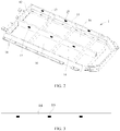
- FIG. 7 is an exploded view of a structure of the exhaust assembly in the lower box body according to an embodiment of this application
- FIG. 8 is a schematic structural diagram of the ventilation frame of the exhaust assembly in the lower box body according to an embodiment of this application
- FIG. 9 is an enlarged diagram of A in FIG. 8
- FIG. 10 is a schematic structural diagram of the baffle of the exhaust assembly in the lower box body according to an embodiment of this application
- FIG. 11 is an enlarged diagram of B in FIG. 10
- FIG. 12 is a schematic structural diagram of a rotating shaft of the exhaust assembly in the lower box body according to an embodiment of this application.
- the ventilation frame 151 includes a first body 151a and a first connection part 151b that are connected; and the first body 151a is in a mesh structure, so that high-temperature gas can penetrate the mesh structure and enter the exhaust channel 142.
- the baffle 152 includes a second body 152a and a second connection part 152b that are connected; the exhaust assembly 15 further includes a rotating shaft 154; and the first connection part 151b and the second connection part 152b are rotatably connected through the rotating shaft 154.
- the second body 152a When the pressure of the accommodating area 16 does not reach the set value, the second body 152a covers the first body 151a; and when the pressure of the accommodating area 16 reaches the set value, the second body 152a is separated from the first body 151a, so that the gas penetrates the first body 151a and enters the exhaust channel 142.
- an upper part between ventilation frame 151 and the baffle 152 is rotatably connected.
- the baffle 152 can rotates so that the high-temperature gas can penetrate the ventilation frame 151 and enter the exhaust channel 142.
- the baffle 152 can open and close smoother, so as to quickly respond to occurrence of thermal runaway.
- the first connection part 151b includes more than two fixing lugs 151c, and the fixing lug 151c is provided with a first fixing hole 151d;
- the second connection part 152b includes more than two fixing posts 152c, and the fixing post 152c is provided with a second fixing hole 152d; and each fixing post 152c is arranged between adjacent fixing lugs 151c, and the rotating shaft 154 passes through the first fixing hole 151d and the second fixing hole 152d to connect the fixing post 152c with the fixing lug 151c.
- a "hinge type" connection is formed between the ventilation frame 151 and the baffle 152, which is easy to realize and has a high connection reliability.
- the rotating shaft 154 includes a third body 154a and a first restraint member 154b and a second restraint member 154c, the first restraint member and the second restraint member being connected to both ends of the third body 154a; the third body 154a passes through and is arranged in the first fixing hole 151d and the second fixing hole 152d; and the first restraint member 154b and the second restraint member 154c are configured to limit axial X movement of the fixing post 152c.
- the first restraint member 154b and the second restraint member 154c are arranged at both ends of the third body 154a to limit the axial X movement of the fixing post 152c, thereby preventing the rotating shaft 154 from coming out, and improving the connection reliability between the ventilation frame 151 and the baffle 152.
- the ventilation frame 151 is provided with a first attraction component 155; the baffle 152 is provided with a second attraction component 156; and the ventilation frame 151 and the baffle 152 are attracted through the first attraction component 155 and the second attraction component 156.
- the ventilation frame 151 and the baffle 152 can remain relatively closed when thermal runaway does not occur in the battery cell 3, thereby preventing external moisture or dust from entering the battery cell 3 and affecting the performance of the battery cell 3.
- the first attraction component 155 is arranged on a side of the ventilation frame 151 away from the baffle 152; and the second attraction component 156 is arranged on a side of the baffle 152 away from the ventilation frame 151.
- the first attraction component 155 and the second attraction component 156 are located relatively far away, so that an attraction force will not be too large, and therefore, this does not cause difficulty in opening the baffle 152 and the ventilation frame 151. It may be understood that the first attraction component 155 may also be arranged on a side of the ventilation frame 151 close to the baffle 152; and the second attraction component 156 is arranged on a side of the baffle 152 close to the ventilation frame 151, which is not further limited herein.
- a sealing component 153 is arranged between the ventilation frame 151 and the baffle 152.
- the sealing component 153 may be a rubber ring. By providing the sealing component 153, sealing performance between the ventilation frame 151 and the baffle 152 can be improved to further prevent external moisture and dust from entering the battery cell.
- a melting point of the exhaust assembly 15 is higher than a melting point of the lower box body 1.
- the melting point of the exhaust assembly 15 is relatively high, so as to prevent the exhaust assembly 15 from being melted by the high-temperature gas when thermal runaway occurs in the battery cell 3, causing the exhaust assembly 15 to fail.
- the lower box body 1 includes a lateral beam 11, a transverse beam 12, a medial transverse beam 13, and a medial vertical beam 14; the lateral beam 11 and the transverse beam 12 are connected end to end to form a frame structure; the medial transverse beam 13 and the medial vertical beam 14 are cross-connected in the frame structure, and the medial transverse beam 13, the medial vertical beam 14 and the lateral beam 11 and/or the transverse beam 12 form the accommodating area 16; and the exhaust assembly 15 is arranged on the medial vertical beam 14 and/or the lateral beam 11.
- the exhaust port 141 and the exhaust assembly 15 are respectively arranged on the medial vertical beam 14 and the lateral beam 11.
- a plurality of battery cells 3 can form a battery array.
- the explosion-proof valve on the battery cell 3 will usually face the medial transverse beam 13 and the lateral beam 11. Once thermal runaway occurs in the battery cell, the high-temperature gas generated inside the battery cell 3 is ejected through the explosion-proof valve and can directly enter the exhaust channel 142, thereby avoiding diffusion of the high-temperature gas.
- each accommodating area 16 is provided with the exhaust port 141 and the exhaust assembly 15.
- the foregoing exhaust port 141 and exhaust assembly 15 are provided for each accommodating area 16 where the battery cell 3 is placed.
- high-temperature gas can be discharged in time to prevent adjacent or nearby battery cell 3 from thermal runaway.
- the exhaust assembly 15 is welded or adhered to the lower box body 1 on the periphery of the exhaust port 141.
- the exhaust assembly 15 may be embedded in the exhaust port 141 by means of welding or adhering, to avoid occupying too much space, thereby increasing an energy density of the battery pack 100.
- the exhaust assembly 15 may also be connected to the lower box body 1 through a connector such as a bolt, and other connection methods may also be used, which is not specifically limited herein.
- the embodiment of this application also provides a vehicle, including the battery pack 100 according to any embodiment of this application.
Abstract
Description
- This application claims priority to
Chinese Patent Application No. 201921564496.X, filed with the Chinese Patent Office on September 19, 2019 - This application relates to the field of energy storage device technologies, and in particular, to a lower box body, a battery pack and a vehicle.
- As an important part of new energy vehicles, a battery pack has extremely important safety performance. The battery pack includes a plurality of battery cells. Once thermal runaway occurs in the battery cell, generated gas may be discharged through an explosion-proof valve of the battery pack.
- However, because a position of a battery cell in which thermal runaway occurs in the plurality of battery cells is uncontrollable, once thermal runaway occurs, generated gas may cause chain thermal runaway of other battery cells. Therefore, it is necessary to design a new battery pack to prevent the battery cell from affecting other battery cells when thermal runaway occurs.
- The embodiments of this application provide a lower box body, a battery pack and a vehicle to resolve the problem in the prior art and improve safety performance of the battery pack.
- A first aspect of the embodiments of this application provides a lower box body, including:
The lower box body has an accommodating area for accommodating a battery cell; the lower box body is further provided with an exhaust port and an exhaust channel, and the exhaust port is in communication with the exhaust channel; the exhaust port is arranged in the corresponding accommodating area; and the lower box body further includes an exhaust assembly, the exhaust assembly is blocked at the exhaust port, and the exhaust assembly is configured to be open when pressure in the accommodating area reaches a set value, so that gas in the accommodating area enters the exhaust channel through the exhaust port. - As a possible design, the exhaust assembly includes a ventilation frame and a baffle; the ventilation frame is close to the accommodating area relative to the baffle; the ventilation frame is connected to a periphery of the exhaust port, and the ventilation frame and the baffle are rotatably connected; when the pressure of the accommodating area does not reach the set value, the baffle covers the ventilation frame; and when the pressure of the accommodating area reaches the set value, the baffle rotates and opens to allow the gas to penetrate the ventilation frame and enter the exhaust channel.
- As a possible design, the ventilation frame includes a first body and a first connection part that are connected; the first body is in a mesh structure;
- the baffle includes a second body and a second connection part that are connected;
- the exhaust assembly further includes a rotating shaft; the first connection part and the second connection part are rotatably connected through the rotating shaft;
- when the pressure of the accommodating area does not reach the set value, the second body covers the first body; and when the pressure of the accommodating area reaches the set value, the second body is separated from the first body, so that the gas penetrates the first body and enters the exhaust channel.
- As a possible design, the first connection part includes more than two fixing lugs, and a fixing lug is provided with a first fixing hole; the second connection part includes more than two fixing posts, and the fixing post is provided with a second fixing hole; and each fixing post is arranged between adjacent fixing lugs, and the rotating shaft passes through the first fixing hole and the second fixing hole to connect the fixing post with the fixing lug.
- As a possible design, the rotating shaft includes a third body, a first restraint member and a second restraint member, the first restraint member and the second restraint member being connected to both ends of the third body; the third body passes through and is arranged in the first fixing hole and the second fixing hole; and the first restraint member and the second restraint member are configured to limit axial X movement of the fixing post.
- As a possible design, the ventilation frame is provided with a first attraction component; the baffle is provided with a second attraction component; and the ventilation frame and the baffle are attracted through the first attraction component and the second attraction component.
- As a possible design, a sealing component is arranged between the ventilation frame and the baffle.
- As a possible design, the lower box body includes a lateral beam, a transverse beam, a medial transverse beam, and a medial vertical beam; the lateral beam and the transverse beam are connected end to end to form a frame structure; the medial transverse beam and the medial vertical beam are cross-connected in the frame structure, and the medial transverse beam, the medial vertical beam and the lateral beam and/or the transverse beam form the accommodating area; and the exhaust assembly is arranged on the medial vertical beam and/or the lateral beam.
- As a possible design, there are more than two accommodating areas; and each accommodating area is provided with the exhaust port and the exhaust assembly.
- As a possible design, the exhaust assembly is welded or adhered to the lower box body on the periphery of the exhaust port.
- A second aspect of the embodiments of this application provides a battery pack, including a battery cell, where the battery pack further includes the lower box body according to any one of the foregoing descriptions, and the battery cell is accommodated in the accommodating area.
- A third aspect of the embodiments of this application provides a vehicle, including the foregoing battery pack.
- The technical solutions provided in the embodiments of this application have the following beneficial effects:
In the lower box body, the battery pack, and the vehicle provided in the embodiments of this application, the lower box body has an accommodating area, and the battery cell is accommodated in the accommodating area. The lower box body is further provided with the exhaust port and the exhaust channel, and the exhaust assembly is set to be open when the pressure of the accommodating area reaches the set value, so that gas in the accommodating area enters the exhaust channel through the exhaust port. In the battery pack provided in the embodiments of this application, once thermal runaway occurs in a battery cell, it will produce a large amount of high-temperature gas inside. The high-temperature gas can penetrate the exhaust assembly and enter the exhaust channel, and then be discharged to the outside of the battery pack. In this way, the probability of thermal runaway of adjacent battery cells can be reduced, thereby improving safety performance of the battery pack. - It should be understood that the general description above and the following details are only exemplary and cannot limit this application.
- To illustrate the implementations of this application or the technical solutions in the prior art more clearly, the following will briefly introduce the drawings that need to be used in the implementations or description of the prior art. Obviously, the drawings described below are implementations of this application, and for a person of ordinary skill in the art, other drawings may also be obtained based on these drawings without creative work.
-
FIG. 1 is a schematic exploded view of a structure of a battery pack according to an embodiment of this application; -
FIG. 2 is a schematic structural diagram of a lower box body according to an embodiment of this application; -
FIG. 3 is a schematic structural diagram of cooperation of a medial vertical beam in the lower box body and an exhaust assembly according to an embodiment of this application; -
FIG. 4 is a schematic exploded view of cooperation of the medial vertical beam in the lower box body and the exhaust assembly according to an embodiment of this application; -
FIG. 5 is a schematic diagram of a closed exhaust assembly in the lower box body according to an embodiment of this application; -
FIG. 6 is a schematic diagram of an open exhaust assembly in the lower box body according to an embodiment of this application; -
FIG. 7 is an exploded view of a structure of the exhaust assembly in the lower box body according to an embodiment of this application; -
FIG. 8 is a schematic structural diagram of a ventilation frame of the exhaust assembly in the lower box body according to an embodiment of this application; -
FIG. 9 is an enlarged diagram of A inFIG. 8 ; -
FIG. 10 is a schematic structural diagram of a baffle of the exhaust assembly in the lower box body according to an embodiment of this application; -
FIG. 11 is an enlarged diagram of B inFIG. 10 ; and -
FIG. 12 is a schematic structural diagram of a rotating shaft of the exhaust assembly in the lower box body according to an embodiment of this application. -
- 100-battery pack;
- 1- lower box body;
- 11-lateral beam;
- 12-transverse beam;
- 13-medial transverse beam;
- 14-medial vertical beam;
- 141-exhaust port;
- 142-exhaust channel;
- 15-exhaust assembly;
- 151-ventilation frame;
- 151a-first body;
- 15 1b-first connection part;
- 151c-fixing lug;
- 151d-first fixing hole;
- 152-baffle;
- 152a-second body;
- 152b-second connection part;
- 152c-fixing post;
- 152d-second fixing hole;
- 153-sealing component;
- 154-rotating shaft;
- 154a-third body;
- 154b-first restraint member;
- 154c-second restraint member;
- 155-first attraction component;
- 156-second attraction component;
- 16-accommodating area;
- 2-box body upper cover;
- 3-battery cell.
- The drawings herein are incorporated into the specification and constitute a part of the specification, showing embodiments that conform to this application, and are used with the specification to explain principles of this application.
- The technical solutions of this application will be clearly and completely described below in combination with the accompanying drawings. Obviously, the described embodiments are a part of the embodiments of this application, rather than all of the embodiments. Based on the embodiments in this application, all other embodiments obtained by a person of ordinary skill in the art without creative work shall fall within the protection scope of this application.
- The terms used in the embodiments of this application are only for the purpose of describing specific embodiments, and are not intended to limit this application. The singular forms of "a" and "the" used in the embodiments and claims of this application are also intended to include plural forms, unless the context clearly indicates other meanings.
- It should be understood that the term "and/or" used in this specification is only an association relationship describing associated objects, which means that there can be three types of relationships, for example, A and/or B may mean that there is A alone, there are A and B, and there is B alone. In addition, the character "/" in this specification usually indicates that the associated objects before and after are in an "or" relationship.
- It should be noted that the noun of locality such as "upper", "lower", "left", and "right" described in the embodiments of this application are described from the angle shown in the accompanying drawings, and should not be understood as a limitation to the embodiments of this application. In addition, in the context, it should also be understood that when referring to that an element is connected "on" or "under" another element, it can not only be directly connected "on" or "under" another element, but also be indirectly connected "on" or "under" another element through an intermediate element.
-
FIG. 1 is a schematic exploded view of a structure of a battery pack according to an embodiment of this application, andFIG. 2 is a schematic structural diagram of a lower box body according to an embodiment of this application. - As shown in
FIG. 1 andFIG. 2 , the embodiment of this application provides abattery pack 100, including alower box body 1 and abattery cell 3. - The
lower box body 1 has anaccommodating area 16, there may be a plurality ofbattery cells 3, and the plurality ofbattery cells 3 form an array accommodated in the foregoingaccommodating area 16. Thebattery pack 100 may further include a box bodyupper cover 2, and the box bodyupper cover 2 is fixed to thelower box body 1 to enclose thebattery cell 3 in thelower box body 1. - When thermal runaway occurs in the
battery cell 3, a large amount of high-temperature gas will be generated inside thebattery cell 3. Once the high-temperature gas is not discharged in time, it will cause abattery cell 3 adjacent to therunaway battery cell 3 to be runaway. - Therefore, the embodiment of this application further provides a lower box body, and the
lower box body 1 is further provided with anexhaust port 141 and anexhaust channel 142. The foregoingexhaust port 141 andexhaust assembly 15 may be arranged on a medialvertical beam 14 of the lower box body. -
FIG. 3 is a schematic structural diagram of cooperation of the medial vertical beam in the lower box body and the exhaust assembly according to an embodiment of this application, andFIG. 4 is a schematic exploded view of cooperation of the medial vertical beam in the lower box body and the exhaust assembly according to an embodiment of this application. - As shown in
FIG. 3 andFIG. 4 , in this embodiment, that theexhaust port 141 and theexhaust assembly 15 are arranged on the medialvertical beam 14 is taken as an example for description. A person skilled in the art may understand that theexhaust port 141 and theexhaust assembly 15 may also be arranged in other positions of thelower box body 1. - Specifically, as shown in
FIG. 2 to FIG. 4 , theexhaust channel 142 is arranged inside the medialvertical beam 14, theexhaust port 141 is in communication with theexhaust channel 142, and theexhaust port 141 is arranged in a correspondingaccommodating area 16. - The
lower box body 1 further includes theexhaust assembly 15 which is blocked at theexhaust port 141, and theexhaust assembly 15 is configured to be open when a pressure of theaccommodating area 16 reaches a set value, so that gas in theaccommodating area 16 enters theexhaust channel 142 through theexhaust port 141. - In the
battery pack 100 provided in the embodiment of this application, once thermal runaway occurs in abattery cell 3, it will produce a large amount of high-temperature gas inside. The high-temperature gas can penetrate theexhaust assembly 15 and enter theexhaust channel 142, and then be discharged to the outside of thebattery pack 100. In this way, probability of thermal runaway ofadjacent battery cells 3 can be reduced, thereby improving safety performance of thebattery pack 100. - When the foregoing
lower box body 1 is processed, theexhaust channel 142 may be molded first. For example, when the medialvertical beam 14 is molded, theexhaust channel 142 is formed, then theexhaust port 141 is processed in thelower box body 1, and theexhaust assembly 15 is installed in theexhaust port 141. In this way, when the pressure of theaccommodating area 16 reaches the set value, theexhaust assembly 15 is configured to be opened so that the gas in theaccommodating area 16 enters theexhaust channel 142 through theexhaust port 141. -
FIG. 5 is a schematic diagram of a closed exhaust assembly in the lower box body according to an embodiment of this application, andFIG. 6 is a schematic diagram of an open exhaust assembly in the lower box body according to an embodiment of this application. - As a possible implementation, as shown in
FIG. 5 andFIG. 6 , theexhaust assembly 15 includes aventilation frame 151 and abaffle 152; and theventilation frame 151 is close to thebattery cell 3 relative to thebaffle 152. Theventilation frame 151 is connected to a periphery of theexhaust port 141, and theventilation frame 151 and thebaffle 152 are rotatably connected. - Specifically, the
ventilation frame 151 may be fixed on the periphery of the foregoingexhaust port 141, so that when thermal runaway occurs in thebattery cell 3, theventilation frame 151 is fixed and only thebaffle 152 rotates and opens in a direction away from thebattery cell 3, to exhaust unidirectionally. In this way, the high-temperature gas generated by thebattery cell 3 can flow to the outside of thebattery pack 100 without flowing back to theaccommodating area 16, thereby lowering the temperature of theaccommodating area 16 relatively quickly. - When the pressure of the
accommodating area 16 does not reach the set value, thebaffle 152 covers theventilation frame 151; and when the pressure of theaccommodating area 16 reaches the set value, thebaffle 152 rotates and opens to allow the gas to penetrate theventilation frame 151 and enter theexhaust channel 142. - When thermal runaway occurs in the
battery cell 3, a large amount of high-temperature gas is generated inside thebattery cell 3, and the high-temperature gas penetrates theventilation frame 151 and acts on thebaffle 152. Thebaffle 152 rotates and opens under the push of the high-temperature gas, so that the gas may penetrate theventilation frame 151 and enter theexhaust channel 142, and then be discharged to the outside of thebattery pack 100. - The
battery pack 100 provided in the embodiment of this application is provided with theexhaust assembly 15 including theventilation frame 151 and thebaffle 152, and the two are configured to be opened and closed relatively rotatably. When thermal runaway occurs in thebattery cell 3, the high-temperature gas can penetrate theventilation frame 151 and be discharged to the outside of thebattery pack 100 after thebaffle 152 is opened. When thermal runaway does not occur in thebattery cell 3, thebaffle 152 can cover theventilation frame 151, so that impurities such as moisture or dust outside thebattery pack 100 will not enter thebattery pack 100 and affect the performance of thebattery cell 3. -
FIG. 7 is an exploded view of a structure of the exhaust assembly in the lower box body according to an embodiment of this application;FIG. 8 is a schematic structural diagram of the ventilation frame of the exhaust assembly in the lower box body according to an embodiment of this application;FIG. 9 is an enlarged diagram of A inFIG. 8 ;FIG. 10 is a schematic structural diagram of the baffle of the exhaust assembly in the lower box body according to an embodiment of this application;FIG. 11 is an enlarged diagram of B inFIG. 10 ; andFIG. 12 is a schematic structural diagram of a rotating shaft of the exhaust assembly in the lower box body according to an embodiment of this application. - As shown in
FIG. 7 to FIG. 12 , there are many forms of connection between theventilation frame 151 and thebaffle 152. As a possible implementation, theventilation frame 151 includes afirst body 151a and afirst connection part 151b that are connected; and thefirst body 151a is in a mesh structure, so that high-temperature gas can penetrate the mesh structure and enter theexhaust channel 142. - The
baffle 152 includes asecond body 152a and asecond connection part 152b that are connected; theexhaust assembly 15 further includes arotating shaft 154; and thefirst connection part 151b and thesecond connection part 152b are rotatably connected through therotating shaft 154. - When the pressure of the
accommodating area 16 does not reach the set value, thesecond body 152a covers thefirst body 151a; and when the pressure of theaccommodating area 16 reaches the set value, thesecond body 152a is separated from thefirst body 151a, so that the gas penetrates thefirst body 151a and enters theexhaust channel 142. - Based on the foregoing structure, an upper part between
ventilation frame 151 and thebaffle 152 is rotatably connected. When thermal runaway occurs in thebattery cell 3, thebaffle 152 can rotates so that the high-temperature gas can penetrate theventilation frame 151 and enter theexhaust channel 142. Through the way of rotating shaft connection, thebaffle 152 can open and close smoother, so as to quickly respond to occurrence of thermal runaway. - As a possible implementation, the
first connection part 151b includes more than two fixinglugs 151c, and the fixinglug 151c is provided with afirst fixing hole 151d; thesecond connection part 152b includes more than two fixingposts 152c, and the fixingpost 152c is provided with asecond fixing hole 152d; and each fixingpost 152c is arranged between adjacent fixinglugs 151c, and therotating shaft 154 passes through thefirst fixing hole 151d and thesecond fixing hole 152d to connect the fixingpost 152c with the fixinglug 151c. - Based on the foregoing structure, a "hinge type" connection is formed between the
ventilation frame 151 and thebaffle 152, which is easy to realize and has a high connection reliability. - As a possible implementation, the
rotating shaft 154 includes athird body 154a and afirst restraint member 154b and asecond restraint member 154c, the first restraint member and the second restraint member being connected to both ends of thethird body 154a; thethird body 154a passes through and is arranged in thefirst fixing hole 151d and thesecond fixing hole 152d; and thefirst restraint member 154b and thesecond restraint member 154c are configured to limit axial X movement of the fixingpost 152c. - The
first restraint member 154b and thesecond restraint member 154c are arranged at both ends of thethird body 154a to limit the axial X movement of the fixingpost 152c, thereby preventing therotating shaft 154 from coming out, and improving the connection reliability between theventilation frame 151 and thebaffle 152. - As a possible implementation, the
ventilation frame 151 is provided with afirst attraction component 155; thebaffle 152 is provided with asecond attraction component 156; and theventilation frame 151 and thebaffle 152 are attracted through thefirst attraction component 155 and thesecond attraction component 156. - In this embodiment, by providing the
first attraction component 155 and thesecond attraction component 156, theventilation frame 151 and thebaffle 152 can remain relatively closed when thermal runaway does not occur in thebattery cell 3, thereby preventing external moisture or dust from entering thebattery cell 3 and affecting the performance of thebattery cell 3. - As a possible implementation, the
first attraction component 155 is arranged on a side of theventilation frame 151 away from thebaffle 152; and thesecond attraction component 156 is arranged on a side of thebaffle 152 away from theventilation frame 151. - In the foregoing structure, the
first attraction component 155 and thesecond attraction component 156 are located relatively far away, so that an attraction force will not be too large, and therefore, this does not cause difficulty in opening thebaffle 152 and theventilation frame 151. It may be understood that thefirst attraction component 155 may also be arranged on a side of theventilation frame 151 close to thebaffle 152; and thesecond attraction component 156 is arranged on a side of thebaffle 152 close to theventilation frame 151, which is not further limited herein. - As a possible implementation, a
sealing component 153 is arranged between theventilation frame 151 and thebaffle 152. - The
sealing component 153 may be a rubber ring. By providing thesealing component 153, sealing performance between theventilation frame 151 and thebaffle 152 can be improved to further prevent external moisture and dust from entering the battery cell. - As a possible implementation, a melting point of the
exhaust assembly 15 is higher than a melting point of thelower box body 1. In this embodiment, the melting point of theexhaust assembly 15 is relatively high, so as to prevent theexhaust assembly 15 from being melted by the high-temperature gas when thermal runaway occurs in thebattery cell 3, causing theexhaust assembly 15 to fail. - As a possible implementation, refer to
FIG. 2 , thelower box body 1 includes alateral beam 11, atransverse beam 12, a medialtransverse beam 13, and a medialvertical beam 14; thelateral beam 11 and thetransverse beam 12 are connected end to end to form a frame structure; the medialtransverse beam 13 and the medialvertical beam 14 are cross-connected in the frame structure, and the medialtransverse beam 13, the medialvertical beam 14 and thelateral beam 11 and/or thetransverse beam 12 form theaccommodating area 16; and theexhaust assembly 15 is arranged on the medialvertical beam 14 and/or thelateral beam 11. In this embodiment, theexhaust port 141 and theexhaust assembly 15 are respectively arranged on the medialvertical beam 14 and thelateral beam 11. - As mentioned above, a plurality of
battery cells 3 can form a battery array. When the plurality ofbattery cells 3 are placed in the accommodating area, the explosion-proof valve on thebattery cell 3 will usually face the medialtransverse beam 13 and thelateral beam 11. Once thermal runaway occurs in the battery cell, the high-temperature gas generated inside thebattery cell 3 is ejected through the explosion-proof valve and can directly enter theexhaust channel 142, thereby avoiding diffusion of the high-temperature gas. - As a possible implementation, there are more than two
accommodating areas 16; and eachaccommodating area 16 is provided with theexhaust port 141 and theexhaust assembly 15. - The foregoing
exhaust port 141 andexhaust assembly 15 are provided for eachaccommodating area 16 where thebattery cell 3 is placed. When thermal runaway occurs in anybattery cell 3, high-temperature gas can be discharged in time to prevent adjacent ornearby battery cell 3 from thermal runaway. - As a possible implementation, the
exhaust assembly 15 is welded or adhered to thelower box body 1 on the periphery of theexhaust port 141. - Specifically, the
exhaust assembly 15 may be embedded in theexhaust port 141 by means of welding or adhering, to avoid occupying too much space, thereby increasing an energy density of thebattery pack 100. - Certainly, the
exhaust assembly 15 may also be connected to thelower box body 1 through a connector such as a bolt, and other connection methods may also be used, which is not specifically limited herein. - The embodiment of this application also provides a vehicle, including the
battery pack 100 according to any embodiment of this application. - The description above is only preferable embodiments of this application, and is not used to limit this application. For a person skilled in the art, this application may have various modifications and changes. Any modification, equivalent replacement and improvement made within the spirit and principle of this application shall be included in the protection scope of this application.
Claims (11)
- A lower box body, wherein the lower box body (1) has an accommodating area (16) for accommodating a battery cell (3);the lower box body (1) is further provided with an exhaust port (141) and an exhaust channel (142), and the exhaust port (141) is in communication with the exhaust channel (142); the exhaust port (141) is arranged in the corresponding accommodating area (16); andthe lower box body (1) further comprises an exhaust assembly (15), the exhaust assembly (15) is blocked at the exhaust port (141), and the exhaust assembly (15) is configured to be open when pressure in the accommodating area (16) reaches a set value, so that gas in the accommodating area (16) enters the exhaust channel (142) through the exhaust port (141).
- The lower box body according to claim 1, wherein the exhaust assembly (15) comprises a ventilation frame (151) and a baffle (152); the ventilation frame (151) is close to the accommodating area (16) relative to the baffle (152);the ventilation frame (151) is connected to a periphery of the exhaust port (141), and the ventilation frame (151) and the baffle (152) are rotatably connected;when the pressure of the accommodating area (16) does not reach the set value, the baffle (152) covers the ventilation frame (151); andwhen the pressure of the accommodating area (16) reaches the set value, the baffle (152) rotates and opens to allow the gas to penetrate the ventilation frame (151) and enter the exhaust channel (142).
- The lower box body according to claim 2, wherein the ventilation frame (151) comprises a first body (151a) and a first connection part (151b) that are connected; the first body (151a) is in a mesh structure;the baffle (152) comprises a second body (152a) and a second connection part (152b) that are connected;the exhaust assembly (15) further comprises a rotating shaft (154);the first connection part (151b) and the second connection part (152b) are rotatably connected through the rotating shaft (154);when the pressure of the accommodating area (16) does not reach the set value, the second body (152a) covers the first body (151a); andwhen the pressure of the accommodating area (16) reaches the set value, the second body (152a) is separated from the first body (151a), so that the gas penetrates the first body (151a) and enters the exhaust channel (142).
- The lower box body according to claim 3, wherein the first connection part (151b) comprises more than two fixing lugs (151c), and a fixing lug (151c) is provided with a first fixing hole (151d);the second connection part (152b) comprises more than two fixing posts (152c), and a fixing post (152c) is provided with a second fixing hole (152d); andeach of the fixing posts (152c) is arranged between adjacent fixing lugs (151c), and the rotating shaft (154) passes through the first fixing hole (151d) and the second fixing hole (152d) to connect the fixing post (152c) with the fixing lug (151c).
- The lower box body according to claim 4, wherein the rotating shaft (154) comprises a third body (154a), a first restraint member (154b) and a second restraint member (154c), the first restraint member (154b) and the second restraint member (154c) being connected to both ends of the third body (154a);the third body (154a) passes through and is arranged in the first fixing hole (151d) and the second fixing hole (152d); andthe first restraint member (154b) and the second restraint member (154c) are configured to limit axial (X) movement of the fixing post (152c).
- The lower box body according to any one of claims 2 to 5, wherein the ventilation frame (151) is provided with a first attraction component (155); the baffle (152) is provided with a second attraction component (156); and
the ventilation frame (151) and the baffle (152) are attracted through the first attraction component (155) and the second attraction component (156). - The lower box body according to any one of claims 2 to 6, wherein a sealing component (153) is arranged between the ventilation frame (151) and the baffle (152).
- The lower box body according to any one of claims 1 to 7, wherein the lower box body (1) comprises a lateral beam (11), a transverse beam (12), a medial transverse beam (13), and a medial vertical beam (14);the lateral beam (11) and the transverse beam (12) are connected end to end to form a frame structure;the medial transverse beam (13) and the medial vertical beam (14) are cross-connected in the frame structure, and the medial transverse beam (13), the medial vertical beam (14) and the lateral beam (11) and/or the transverse beam (12) form the accommodating area (16); andthe exhaust assembly (15) is arranged on the medial vertical beam (14) and/or the lateral beam (11).
- The lower box body according to any one of claims 1 to 8, wherein there are more than two accommodating areas (16); and
each accommodating area (16) is provided with the exhaust port (141) and the exhaust assembly (15). - A battery pack, comprising a battery cell (3), wherein the battery pack (100) further comprises the lower box body (1) according to any one of claims 1 to 9, and the battery cell (3) is accommodated in the accommodating area (16).
- A vehicle, comprising the battery pack (100) according to claim 10.
Applications Claiming Priority (2)
| Application Number | Priority Date | Filing Date | Title |
|---|---|---|---|
| CN201921564496.XU CN210110904U (en) | 2019-09-19 | 2019-09-19 | Lower box, battery package and vehicle |
| PCT/CN2020/106461 WO2021052037A1 (en) | 2019-09-19 | 2020-07-31 | Lower box body, battery pack and vehicle |
Publications (2)
| Publication Number | Publication Date |
|---|---|
| EP3916894A1 true EP3916894A1 (en) | 2021-12-01 |
| EP3916894A4 EP3916894A4 (en) | 2022-05-18 |
Family
ID=69532013
Family Applications (1)
| Application Number | Title | Priority Date | Filing Date |
|---|---|---|---|
| EP20865202.4A Pending EP3916894A4 (en) | 2019-09-19 | 2020-07-31 | Lower box body, battery pack and vehicle |
Country Status (4)
| Country | Link |
|---|---|
| US (1) | US20210402884A1 (en) |
| EP (1) | EP3916894A4 (en) |
| CN (1) | CN210110904U (en) |
| WO (1) | WO2021052037A1 (en) |
Cited By (2)
| Publication number | Priority date | Publication date | Assignee | Title |
|---|---|---|---|---|
| WO2023234734A1 (en) * | 2022-06-03 | 2023-12-07 | 주식회사 엘지에너지솔루션 | Battery pack |
| WO2023234735A1 (en) * | 2022-06-03 | 2023-12-07 | 주식회사 엘지에너지솔루션 | Battery pack |
Families Citing this family (18)
| Publication number | Priority date | Publication date | Assignee | Title |
|---|---|---|---|---|
| CN210110904U (en) * | 2019-09-19 | 2020-02-21 | 宁德时代新能源科技股份有限公司 | Lower box, battery package and vehicle |
| CN111224039B (en) * | 2020-04-22 | 2020-07-24 | 江苏时代新能源科技有限公司 | Casing, group battery and device |
| US20210359374A1 (en) * | 2020-05-12 | 2021-11-18 | Samsung Sdi Co., Ltd. | Battery system and vehicle including the battery system |
| CN112704832A (en) * | 2020-12-29 | 2021-04-27 | 长城汽车股份有限公司 | Battery box and battery package |
| CN113193259A (en) * | 2021-04-16 | 2021-07-30 | 湖北亿纬动力有限公司 | Battery pack and electric automobile |
| CN117412880A (en) * | 2021-05-25 | 2024-01-16 | 日产自动车株式会社 | Battery frame for vehicle |
| KR20220169704A (en) * | 2021-06-21 | 2022-12-28 | 주식회사 엘지에너지솔루션 | Battery pack and device including the same |
| CN116438695A (en) * | 2021-07-29 | 2023-07-14 | 宁德时代新能源科技股份有限公司 | Battery, power utilization device, method for preparing battery and device for preparing battery |
| WO2023004777A1 (en) * | 2021-07-30 | 2023-02-02 | 宁德时代新能源科技股份有限公司 | Battery box body, battery, electric device, and battery preparation method and device |
| KR102639671B1 (en) * | 2021-08-25 | 2024-02-21 | 주식회사 엘지에너지솔루션 | Battery module and battery pack including the same |
| CN216850203U (en) * | 2021-11-08 | 2022-06-28 | 宁德时代新能源科技股份有限公司 | Battery box, battery and power consumption device |
| CN113771648B (en) * | 2021-11-12 | 2022-02-15 | 长城汽车股份有限公司 | Vehicle with a steering wheel |
| CN114678638B (en) * | 2022-03-31 | 2023-08-15 | 欣旺达电动汽车电池有限公司 | Exhaust assembly, battery module and battery pack |
| CN114678639B (en) * | 2022-03-31 | 2023-07-14 | 欣旺达电动汽车电池有限公司 | Module upper cover, battery module and battery pack |
| WO2023229373A1 (en) * | 2022-05-27 | 2023-11-30 | 주식회사 엘지에너지솔루션 | Battery pack and device including same |
| WO2024048456A1 (en) * | 2022-09-02 | 2024-03-07 | 株式会社Aescジャパン | Battery pack |
| WO2024053277A1 (en) * | 2022-09-07 | 2024-03-14 | パナソニックエナジー株式会社 | Battery pack |
| CN115548549A (en) * | 2022-11-01 | 2022-12-30 | 江苏正力新能电池技术有限公司 | Battery pack |
Family Cites Families (16)
| Publication number | Priority date | Publication date | Assignee | Title |
|---|---|---|---|---|
| JP4768277B2 (en) * | 2005-01-28 | 2011-09-07 | プライムアースEvエナジー株式会社 | Cooling device and power supply device |
| JP5092657B2 (en) * | 2007-09-28 | 2012-12-05 | 三菱自動車工業株式会社 | Battery unit |
| JP4386131B2 (en) * | 2007-12-05 | 2009-12-16 | 三菱自動車工業株式会社 | Electric car |
| US8268469B2 (en) * | 2009-04-22 | 2012-09-18 | Tesla Motors, Inc. | Battery pack gas exhaust system |
| WO2012140727A1 (en) * | 2011-04-12 | 2012-10-18 | 日立ビークルエナジー株式会社 | Secondary battery module |
| JP5880086B2 (en) * | 2012-01-31 | 2016-03-08 | 三菱自動車工業株式会社 | Battery container |
| US10720683B2 (en) * | 2014-09-30 | 2020-07-21 | Cps Technology Holdings Llc | Battery module thermal management features for internal flow |
| KR102091770B1 (en) * | 2016-05-31 | 2020-03-23 | 주식회사 엘지화학 | Battery module, battery pack comprising the battery module and vehicle comprising the battery pack |
| JP7359527B2 (en) * | 2017-05-31 | 2023-10-11 | トヨタ自動車株式会社 | Battery mounting structure |
| CN207409561U (en) * | 2017-11-02 | 2018-05-25 | 宁德时代新能源科技股份有限公司 | Battery case and battery pack |
| JP6935746B2 (en) * | 2017-12-27 | 2021-09-15 | トヨタ自動車株式会社 | In-vehicle battery device |
| CN209104230U (en) * | 2018-12-27 | 2019-07-12 | 宁德时代新能源科技股份有限公司 | A kind of battery case |
| CN110190212B (en) * | 2018-12-29 | 2020-02-04 | 比亚迪股份有限公司 | Power battery package and vehicle |
| CN209401662U (en) * | 2019-03-28 | 2019-09-17 | 宁德时代新能源科技股份有限公司 | Battery pack |
| CN209401710U (en) * | 2019-03-28 | 2019-09-17 | 宁德时代新能源科技股份有限公司 | Battery modules and battery pack |
| CN210110904U (en) * | 2019-09-19 | 2020-02-21 | 宁德时代新能源科技股份有限公司 | Lower box, battery package and vehicle |
-
2019
- 2019-09-19 CN CN201921564496.XU patent/CN210110904U/en active Active
-
2020
- 2020-07-31 EP EP20865202.4A patent/EP3916894A4/en active Pending
- 2020-07-31 WO PCT/CN2020/106461 patent/WO2021052037A1/en unknown
-
2021
- 2021-09-09 US US17/469,979 patent/US20210402884A1/en active Pending
Cited By (2)
| Publication number | Priority date | Publication date | Assignee | Title |
|---|---|---|---|---|
| WO2023234734A1 (en) * | 2022-06-03 | 2023-12-07 | 주식회사 엘지에너지솔루션 | Battery pack |
| WO2023234735A1 (en) * | 2022-06-03 | 2023-12-07 | 주식회사 엘지에너지솔루션 | Battery pack |
Also Published As
| Publication number | Publication date |
|---|---|
| CN210110904U (en) | 2020-02-21 |
| EP3916894A4 (en) | 2022-05-18 |
| WO2021052037A1 (en) | 2021-03-25 |
| US20210402884A1 (en) | 2021-12-30 |
Similar Documents
| Publication | Publication Date | Title |
|---|---|---|
| EP3916894A1 (en) | Lower box body, battery pack and vehicle | |
| EP2450982B1 (en) | Battery module | |
| JP7391227B2 (en) | Batteries, battery modules, electrical equipment and battery manufacturing methods | |
| EP2410592B1 (en) | Battery module | |
| WO2017143748A1 (en) | Power battery, protection system thereof, and electric vehicle | |
| US8956746B2 (en) | Apparatus, system, and method for battery venting containment | |
| US10804522B2 (en) | Single-cell battery, battery module, power battery, and electric vehicle | |
| KR20220101633A (en) | End Cover Assemblies, Secondary Batteries, Battery Packs and Devices Using Batteries | |
| WO2017143754A1 (en) | Single-cell battery, battery module, battery pack, and electric vehicle | |
| CN208489243U (en) | Secondary cell cap assembly and secondary cell | |
| CN115764150B (en) | Energy storage device and electric equipment | |
| KR20210133535A (en) | Battery pack and device including the same | |
| ES2922198T3 (en) | Power battery and battery module | |
| GB2517468A (en) | Vent apparatus for a battery casing | |
| US11183722B2 (en) | Secondary battery and top cover assembly thereof | |
| KR102248230B1 (en) | Secondary battery module | |
| KR102322910B1 (en) | Battery case, battery pack including the same, and vehicle including the same | |
| CN211455813U (en) | Nickel-hydrogen battery with high-efficient pressure release structure | |
| US20230275315A1 (en) | Battery pack with improved fire protection performance | |
| CN220553552U (en) | Battery module and battery pack including the same | |
| KR102482970B1 (en) | Container unit for electric vehicle fire suppression | |
| CN218827305U (en) | Battery with a battery cell | |
| EP4362195A1 (en) | Battery cell, battery module, battery pack, and vehicle including same | |
| EP4184693A1 (en) | Secondary battery and manufacturing method for same | |
| KR20220039588A (en) | Battery Module, Battery Pack, And Electronic Vehicle Including Same |
Legal Events
| Date | Code | Title | Description |
|---|---|---|---|
| STAA | Information on the status of an ep patent application or granted ep patent |
Free format text: STATUS: THE INTERNATIONAL PUBLICATION HAS BEEN MADE |
|
| PUAI | Public reference made under article 153(3) epc to a published international application that has entered the european phase |
Free format text: ORIGINAL CODE: 0009012 |
|
| STAA | Information on the status of an ep patent application or granted ep patent |
Free format text: STATUS: REQUEST FOR EXAMINATION WAS MADE |
|
| 17P | Request for examination filed |
Effective date: 20210727 |
|
| AK | Designated contracting states |
Kind code of ref document: A1 Designated state(s): AL AT BE BG CH CY CZ DE DK EE ES FI FR GB GR HR HU IE IS IT LI LT LU LV MC MK MT NL NO PL PT RO RS SE SI SK SM TR |
|
| A4 | Supplementary search report drawn up and despatched |
Effective date: 20220414 |
|
| RIC1 | Information provided on ipc code assigned before grant |
Ipc: H01M 50/30 20210101ALI20220408BHEP Ipc: H01M 50/20 20210101AFI20220408BHEP |
|
| DAV | Request for validation of the european patent (deleted) | ||
| DAX | Request for extension of the european patent (deleted) | ||
| STAA | Information on the status of an ep patent application or granted ep patent |
Free format text: STATUS: EXAMINATION IS IN PROGRESS |
|
| 17Q | First examination report despatched |
Effective date: 20230904 |
|
| GRAP | Despatch of communication of intention to grant a patent |
Free format text: ORIGINAL CODE: EPIDOSNIGR1 |
|
| STAA | Information on the status of an ep patent application or granted ep patent |
Free format text: STATUS: GRANT OF PATENT IS INTENDED |
|
| INTG | Intention to grant announced |
Effective date: 20240311 |