EP3916395A1 - Sample analysis system and control method therefor, and sample analysis method - Google Patents
Sample analysis system and control method therefor, and sample analysis method Download PDFInfo
- Publication number
- EP3916395A1 EP3916395A1 EP19931868.4A EP19931868A EP3916395A1 EP 3916395 A1 EP3916395 A1 EP 3916395A1 EP 19931868 A EP19931868 A EP 19931868A EP 3916395 A1 EP3916395 A1 EP 3916395A1
- Authority
- EP
- European Patent Office
- Prior art keywords
- sample
- distribution
- reagent
- node
- measurement
- Prior art date
- Legal status (The legal status is an assumption and is not a legal conclusion. Google has not performed a legal analysis and makes no representation as to the accuracy of the status listed.)
- Granted
Links
Images




Classifications
-
- G—PHYSICS
- G01—MEASURING; TESTING
- G01N—INVESTIGATING OR ANALYSING MATERIALS BY DETERMINING THEIR CHEMICAL OR PHYSICAL PROPERTIES
- G01N35/00—Automatic analysis not limited to methods or materials provided for in any single one of groups G01N1/00 - G01N33/00; Handling materials therefor
- G01N35/00584—Control arrangements for automatic analysers
- G01N35/0092—Scheduling
-
- G—PHYSICS
- G01—MEASURING; TESTING
- G01N—INVESTIGATING OR ANALYSING MATERIALS BY DETERMINING THEIR CHEMICAL OR PHYSICAL PROPERTIES
- G01N35/00—Automatic analysis not limited to methods or materials provided for in any single one of groups G01N1/00 - G01N33/00; Handling materials therefor
- G01N35/00584—Control arrangements for automatic analysers
-
- G—PHYSICS
- G01—MEASURING; TESTING
- G01N—INVESTIGATING OR ANALYSING MATERIALS BY DETERMINING THEIR CHEMICAL OR PHYSICAL PROPERTIES
- G01N35/00—Automatic analysis not limited to methods or materials provided for in any single one of groups G01N1/00 - G01N33/00; Handling materials therefor
- G01N35/02—Automatic analysis not limited to methods or materials provided for in any single one of groups G01N1/00 - G01N33/00; Handling materials therefor using a plurality of sample containers moved by a conveyor system past one or more treatment or analysis stations
- G01N35/04—Details of the conveyor system
-
- G—PHYSICS
- G01—MEASURING; TESTING
- G01N—INVESTIGATING OR ANALYSING MATERIALS BY DETERMINING THEIR CHEMICAL OR PHYSICAL PROPERTIES
- G01N35/00—Automatic analysis not limited to methods or materials provided for in any single one of groups G01N1/00 - G01N33/00; Handling materials therefor
- G01N35/10—Devices for transferring samples or any liquids to, in, or from, the analysis apparatus, e.g. suction devices, injection devices
- G01N35/1002—Reagent dispensers
-
- G—PHYSICS
- G01—MEASURING; TESTING
- G01N—INVESTIGATING OR ANALYSING MATERIALS BY DETERMINING THEIR CHEMICAL OR PHYSICAL PROPERTIES
- G01N35/00—Automatic analysis not limited to methods or materials provided for in any single one of groups G01N1/00 - G01N33/00; Handling materials therefor
- G01N35/10—Devices for transferring samples or any liquids to, in, or from, the analysis apparatus, e.g. suction devices, injection devices
- G01N35/1081—Devices for transferring samples or any liquids to, in, or from, the analysis apparatus, e.g. suction devices, injection devices characterised by the means for relatively moving the transfer device and the containers in an horizontal plane
- G01N35/1083—Devices for transferring samples or any liquids to, in, or from, the analysis apparatus, e.g. suction devices, injection devices characterised by the means for relatively moving the transfer device and the containers in an horizontal plane with one horizontal degree of freedom
-
- G—PHYSICS
- G01—MEASURING; TESTING
- G01N—INVESTIGATING OR ANALYSING MATERIALS BY DETERMINING THEIR CHEMICAL OR PHYSICAL PROPERTIES
- G01N35/00—Automatic analysis not limited to methods or materials provided for in any single one of groups G01N1/00 - G01N33/00; Handling materials therefor
- G01N2035/00178—Special arrangements of analysers
- G01N2035/00326—Analysers with modular structure
-
- G—PHYSICS
- G01—MEASURING; TESTING
- G01N—INVESTIGATING OR ANALYSING MATERIALS BY DETERMINING THEIR CHEMICAL OR PHYSICAL PROPERTIES
- G01N35/00—Automatic analysis not limited to methods or materials provided for in any single one of groups G01N1/00 - G01N33/00; Handling materials therefor
- G01N35/02—Automatic analysis not limited to methods or materials provided for in any single one of groups G01N1/00 - G01N33/00; Handling materials therefor using a plurality of sample containers moved by a conveyor system past one or more treatment or analysis stations
- G01N35/04—Details of the conveyor system
- G01N2035/046—General conveyor features
- G01N2035/0465—Loading or unloading the conveyor
-
- G—PHYSICS
- G01—MEASURING; TESTING
- G01N—INVESTIGATING OR ANALYSING MATERIALS BY DETERMINING THEIR CHEMICAL OR PHYSICAL PROPERTIES
- G01N35/00—Automatic analysis not limited to methods or materials provided for in any single one of groups G01N1/00 - G01N33/00; Handling materials therefor
- G01N35/02—Automatic analysis not limited to methods or materials provided for in any single one of groups G01N1/00 - G01N33/00; Handling materials therefor using a plurality of sample containers moved by a conveyor system past one or more treatment or analysis stations
- G01N35/04—Details of the conveyor system
- G01N2035/0474—Details of actuating means for conveyors or pipettes
- G01N2035/0482—Transmission
- G01N2035/0484—Belt or chain
Definitions
- the present invention relates to the technical field of automated analysis, and more particularly to a sample analysis system and a control method for the same and a sample analysis method.
- Existing automated analysis systems generally include various components related to sample distribution such as sample aspiration, transfer, and discharge, and various components related to sample analysis such as reagent aspiration, transfer, discharge, incubation, and measurement. These components work in coordination with a mutually restrictive structure and a spatial cooperation relationship, so that a set of complete sample distribution, reagent distribution, transfer, and measurement related modules and components together constitute an independent analysis system.
- the components of this system are designed by a complete set of solutions. Disassembly of components or modules makes the system incapable of normal operation, so the system is indivisible and non-expandable. In such a system, certain component resources will be wasted, and the system cannot perform to its maximum efficiency and is incapable of free combination and efficient expansion.
- U.S. Patent US20180313861A1 discloses a sample analysis system, and its conveying device includes: a robotic arm that conveys a container or a container rack between two sample analysis devices, and a base supporting the robotic arm. With use of this conveying device, it is still essentially a sample conveying solution and does not improve the efficiency of the analyzer system at the analyzer level.
- the above-mentioned patent implements a commercial automated analysis system pipeline, which is formed by connection of independent analysis systems with multiple complete functions. It is bulky, and sample distribution related aspiration, discharge, quantification, and other functional modules, and reagent distribution, incubation, measurement, blending and other related modules are bound in the analysis system and structurally interdependent, and are arranged as a combined instrument unit.
- the relevant modules of the incubation and measurement functions often include speed-limiting steps. For example, in the process of most immune reactions, the testing time for a single reaction reaches a time length of several minutes to tens of minutes, and sample distribution, including aspiration, transfer, and discharge, seldom requires uncertain reaction time limits.
- the pipeline analysis system solution of conventional complete analysis system combination will make a large number of sample related component resources fail to perform to their maximum efficiency, resulting in cost, efficiency, and volume wastes, thereby making it impossible to expand efficiently.
- An embodiment of the present invention provides a sample analysis system intended to solve the problems of bulk and incapability of free combination, high efficiency, and expansion of existing sample analysis systems.
- An embodiment of the present invention provides a sample analysis system including: a control device; a rail device for carrying cuvettes under control of the control device; at least one independent sample distribution node arranged on the rail device for distributing samples to the cuvettes, the independent sample distribution node being used for sample aspiration, transfer, and discharge; and at least two independent reagent distribution and measurement nodes arranged on the rail device for distributing test reagents to the cuvettes and measuring the mixture liquid in the cuvettes, the independent reagent distribution and measurement nodes being used for reagent aspiration, transfer, and discharge and reagent-sample mixture liquid measurement; the cuvettes being used for containing the sample and reagent and signal measurement.
- An embodiment of the present invention further provides that the rail device includes multiple node rails corresponding to the sample distribution node and the reagent distribution and measurement nodes for communication between individual nodes.
- the multiple node rails constitute an integrated synchronized motion structure or a dividable structure consisting of free assembly and combination.
- An embodiment of the present invention further provides that the analysis system has concurrency.
- Combination of a sample distribution node with a reagent distribution and measurement node provides a basic measurement function of the analysis system.
- the reagent distribution and measurement node and sample distribution node beyond the basic measurement function combination constitute concurrent operation nodes.
- An embodiment of the present invention further provides that the analysis system is characterized in that: The sample distribution node and reagent distribution and measurement nodes are combined according to different combination rules and arranged on the rail device to constitute different sample analysis systems. These sample analysis systems can be expanded by adding sample distribution and reagent distribution and measurement nodes and configuring the rail device.
- An embodiment of the present invention further provides that the sample analysis system further includes: a cuvette distribution node for providing cuvettes to other nodes in the sample analysis system.
- An embodiment of the present invention further provides that the reagent distribution and measurement node further includes a blending mechanism for blending the sample, the reagent, and the reagent-sample mixture liquid evenly.
- An embodiment of the present invention further provides that the reagent distribution and measurement node further includes a gripper mechanism and a motion mechanism.
- the gripper mechanism is used for gripping the cuvette on the rail or in a vehicle.
- the motion mechanism is used for bringing and transferring the cuvette gripped by the gripper mechanism to the measurement location at the reagent distribution and measurement node.
- An embodiment of the present invention further provides that the reagent distribution and measurement node further includes a reagent storage module for storing the analysis reagent.
- An embodiment of the present invention further provides that the cuvette is a container made of a solid material to serve as a carrier for sample and reagent distribution, transfer, and measurement.
- An embodiment of the present invention provides a control method for a sample analysis system for controlling the sample analysis system, including the steps of:
- An embodiment of the present invention provides a sample analysis method for the sample analysis system, including the steps of:
- the sample analysis system uses cuvettes as the medium and employs multiple relatively independent sample distribution nodes and multiple relatively independent reagent distribution and measurement nodes that are freely combined and connected via rails, so that the restriction of physical cooperation relationship between sample distribution components and sample analysis components in conventional instruments are eliminated, thereby providing a fully automated analysis system with small size, high efficiency, high freedom, and high expandability.
- the nodes can be freely added and freely combined and connected to form analysis systems with different speeds and analysis functions, thereby significantly improving the utilization of the structural components in the instrument and enabling easy installation and maintenance.
- different distributed sample analysis systems can be assembled from multiple expandable independent sample distribution nodes and reagent distribution and measurement nodes that are freely combined via a rail device under control of a control device.
- a distributed sample analysis system includes:
- Fig. 2 is a view showing assembly and disassembly of said sample analysis system according to the present invention
- Figs. 3a, 3b , and 3c are side and top views showing the implementation of said sample distribution node 1 including a cuvette distribution module
- said distributed sample analysis system can be specifically formed by one sample distribution node 1 including a cuvette distribution module 14 and two reagent distribution and measurement nodes 2 that are detachably assembled and combined via rails 3.
- the manner of assembly and disassembly is shown at A or B in Fig. 2 .
- the cuvette distribution module 14 of the sample distribution node 1 delivers a batch of cuvettes 4 to the node rail 31 of the rail device 3.
- the samples are transferred into the cuvettes 4 by a sample transfer module of the sample distribution node, then transported to the location of the reagent distribution and measurement nodes 2 by the rail device 3, and measured and analyzed in the reagent distribution and measurement nodes 2 thereafter.
- the nodes described above are independent functional units under control of said control device.
- the part of the node rail 32 can be reserved, without influencing the normal use of the sample analysis system, thereby facilitating maintenance.
- the node rail 32 and the reagent distribution and measurement node 2 can be detached and removed together, and the remaining nodes can be stilled assembled and used.
- new nodes can be added. In this way, free combination and efficient expansion of said sample analysis system is achieved.
- multiple sample distribution nodes 1 and reagent distribution and measurement nodes 2 can be selected according to a combination rule.
- Said control device controls the node rail corresponding to these selected nodes to have the nodes assembled onto the rail device 3 so as to communicate the individual nodes, or controls a certain node to be detached and removed from the rail device 3.
- the rail device 3 includes multiple node rails that may constitute an integrated synchronized motion structure or a dividable structure consisting of free assembly and combination.
- the sample distribution nodes 1 and reagent distribution and measurement nodes 2 can be added and arranged onto the rail device 3 for expansion, so as to obtain different sample analysis systems.
- the combination rules include speed priority principle, sample priority principle, resource priority principle, or the like.
- sample analysis system has concurrency. That is, combination of a sample distribution node 1 with a reagent distribution and measurement node 2 provides a basic measurement function of the analysis system.
- the reagent distribution and measurement node and sample distribution node beyond the basic measurement function combination constitute concurrent operation nodes.
- said basic measurement function can still realize the sample analysis process.
- a sample analysis system with a basic measurement function consisting of one sample distribution node 1 combined with one reagent distribution and measurement node 2
- the number of the reagent distribution and measurement nodes 2 can be increased as appropriate (e.g., to two) and these nodes perform measurement concurrently under control of the control system. That is, samples can be distributed to the reagent distribution and measurement nodes 2 successively for concurrent testing, thereby improving the testing efficiency. If one of the reagent distribution and measurement nodes 2 fails or halls, then the remaining nodes can continue to operate and realize the corresponding analysis.
- the concurrency of the sample analysis system may not influence the normal operation of the overall system, thereby facilitating maintenance and repairs.
- said sample distribution node 1 includes: a sample distribution control device; a sample distribution device connected to the sample distribution control device for aspiration, transfer, and discharge of the sample to the cuvette in the current node under control of the sample distribution control device; and a sample distribution node fixing frame 12 for fixing various portions of the sample distribution node to an independent structure.
- Said sample distribution device further includes a node rail module 31, a first cuvette distribution module 14, a sample transfer module 11, and a sample loading region 13.
- An aspiration and discharge component 111 on the sample transfer module 11 aspirates a sample from a sample tube on the sample rack 131 in the sample loading region 13. Then through cooperation of the rail 112 and the sample transfer module 11, the aspiration and discharge component 111 is moved to the location of the cuvette 4 on the node rail module 31, and the sample liquid is discharged to the cuvette 4.
- said aspiration and discharge component 111 includes, without limitation, a quantitative liquid aspiration and discharge component driven by pneumatic, electric, or hydraulic actuation.
- the structure of the sample aspiration component 1111 may be a tubular structure like a sample probe, a sample tube, or the like capable of quick sample aspiration.
- the node rail module 31 is used for transportation of the cuvettes 4.
- the cuvettes 4 may be placed directly on the rail and transported by the rail through mechanical driving such as fixation fitting, friction fitting, convex-concave structure fitting, or the like.
- the cuvettes 4 are preferably in the form of a cuvette row.
- Said rail has a mechanical design including, without limitation, a belt, a gear, a screw, or the like, for transmission movement.
- the cuvettes 4 may alternatively be placed on the node rail 31 by loading the cuvettes 4 onto the vehicle 34 arranged on the node rail 31.
- the vehicle 34 has a solid structure that can receive the cuvette 4.
- the sample distribution node fixing frame 12 is used for fixing various modules and components integrated in the sample distribution node 1.
- the overall sample distribution node 1 has an independent panel 121 fixed thereto (refer to Fig. 1a ) to form a relatively independent functional structure and facilitate combination with other nodes.
- the sample loading region 13 serves as an input region for samples to facilitate transportation of samples to other nodes via the node rail 31.
- the samples are directly placed manually in the sample loading region 13, or fed into the sample loading region 13 via an automated motion mechanism (a mechanism other than the rail).
- Said samples may be distributed to a container directly from a blood collecting tube, manually, or in an automated manner in advance.
- the first cuvette distribution module 14 is used for delivering cuvettes 4 quickly. Numerous cuvettes 4 are stored in a cuvette feeding mechanism 141, then the cuvettes 4 are loaded out of order into a slideway 142, and thereafter the cuvettes 4 arrive at a cuvette tray mechanism 143 under gravity. Thereafter, a gripper mechanism 144 grips and loads empty cuvettes 4 onto the node rail module 31. In this way, the cuvettes 4 can be output in batch and in order, thereby improving the efficiency of cuvette delivery.
- the gripper mechanism 144 drives a gripper structure 1442 in movement through a driving component 1441 into an opened or closed status, so as to mate with the cuvettes 4, thereby improving the gripping efficiency.
- the reagent distribution and measurement node 2 includes: a reagent distribution and measurement control device, a reagent distribution and measurement device connected to the reagent distribution and measurement control device for aspiration, transfer, and discharge of the reagent to the cuvette 4 in the current node for measurement under control of the reagent distribution and measurement control device; and a reagent distribution and measurement node fixing frame 24 for fixing various portions of the reagent distribution and measurement node to an independent structure.
- the reagent distribution and measurement device further includes a node rail module 32, a reagent distribution module 21, a measurement module 23, and a cuvette transfer module 22.
- a gripper mechanism 221 on the cuvette transfer module 22 grips a cuvette 4 loaded with a sample from the node rail 32.
- the cuvette 4 is transferred to an incubation module 25 in the reagent distribution and measurement node 2 by a motion mechanism 222.
- the aspiration and discharge component 211 on the reagent distribution module 21 aspirates analysis reagent from the reagent storage module 26.
- the aspiration and discharge component 211 is moved by a motion mechanism 212 to the location of the cuvette 4 on the incubation module 25 and discharges the aspirated reagent into the cuvette 4.
- a blending mechanism blends the liquid in the cuvette 4 evenly. Thereafter, the cuvette 4 loaded with the mixture liquid of the reagent and the sample is moved to the measurement module 23 through movement of the gripper mechanism 221 and the sample analysis process is completed in the measurement module 23. Then the cuvette 4 is transported by the node rail module 32 to the next functional node.
- Said gripper mechanism 221 and aspiration and discharge component 211 include, without limitation, components driven by pneumatic, electric, or hydraulic actuation.
- the structure of the aspiration and discharge component 211 for reagent aspiration may be a tubular structure such as a reagent probe, a reagent tube, or the like.
- the structure for reagent aspiration includes, without limitation, one enabling aspiration through movement in a pipeline (one with multiple ports, i.e., the liquid transfer process including aspiration through one end and discharge through the other), and one enabling aspiration through reagent probe aspiration and reagent probe displacement (the reagent probe is connected with a spatial motion rail and a transmission mechanism, i.e., the movement in which the reagent probe aspirates reagent, the reagent is spatially moved to a designated location, and the liquid is discharged).
- the motion of the reagent may be a motion such as planer motion, rotation around an axis center over a certain radius, planar and vertical three-dimensional motions, and rotation around an axis center over a certain radius combined with vertical motion, or the like.
- the gripper mechanism 221 may further be connected with a spatial motion mechanism, including, without limitation, a mechanical structure of motion such as planar motion, vertical motion, three-dimensional motion, rotation, or the like, for bringing along the cuvette gripped by the gripper mechanism and transferring it to the measurement location on the reagent distribution and measurement node.
- Said reagent distribution and measurement node further includes a blending mechanism with blending function, specifically, one capable of driving the liquid in movement of blending, including, without limitation, blending through bubbling, agitation, ultrasound, vibration, or the like.
- Said reagent distribution and measurement node further includes a reagent storage module for storage of analysis reagent.
- the reagent storage structure may further include an assembly associated with cooling for cooling the reagent atmosphere in the storage structure down to various temperature ranges, which can provide various levels of temperature regulation based on well-known techniques in the industry.
- the reagent storage module in the reagent distribution and measurement node can operate in two storage modes, i.e. cooling storage and non-cooling storage, so as to provide storage for analysis reagents with different characteristics.
- the reagent distribution and measurement node fixing frame 24 is used for fixing the functional components and modules in the reagent distribution and measurement node.
- the reagent distribution and measurement node fixing frame 24 may further have an independent panel 241 (referring to Fig. 1b ) connected to its surface that is mated thereto to form a relatively independent functional device and also facilitates combination with other nodes.
- the rail of said node rail module 32 has a mechanical design for transmission of movement, including, without limitation, a belt, a gear, a screw, or the like.
- Said cuvette 4 is a container made of solid material, including, without limitation, plastic, glass, quartz, metal, or the like, that cannot be easily broken and can be recycled conveniently.
- the cuvette 4 as the container for a sample may be in the unit of one, or may be in the form of a cuvette row of several connected cuvettes.
- the measurement module 23 may utilize a measurement principle including optical measurement, electrical measurement, acoustical measurement, magnetic measurement, or the like. Examples of the specific testing principle are shown in Figs. 5-7 .
- the sample reacts with the reagent in the cuvette 2321 to generate a particular optical signal, which is collected by a photomultiplier tube (PMT) 2322 and converted into a detectable electric signal. Then the electric signal is collected by a pre-processing circuit 2323 and an AD collection circuit 2324 and processed by a microprocessor 2325 and converted into a displayable digital signal.
- PMT photomultiplier tube
- an anode 2332 and a cathode 2333 are inserted into the cuvette 2331.
- the sample reacts with the reagent to generate an electric signal that can be collected by 2334.
- the collected electric signal is preliminarily processed by a signal conditioning circuit 2335 to condition the signal intensity.
- the electric signal is collected by an AD collection circuit 2336 and converted by a micro-processor 2337 into a displayable digital signal.
- a fixed magnetic field is provided by magnetic bars 2342 and 2343 before and after a cuvette 2341 of a curved track configuration, inducing the magnetic beads 2344 in the cuvette 2341 into reciprocation.
- a magnetic signal is generated after power-on of a magnetic pot 2345 on one side of the cuvette, and can be received by a magnetic pot 2346 on the other side, transmitted over a circuit, and converted into an electric signal.
- the magnetic beads 2344 reciprocate at the same speed so that the electric signal finally formed is displayed on the display end as a regular wave band.
- the solution starts to become cloudy.
- the magnetic beads 2344 are subject to resistance that becomes increasingly greater during the reciprocation and move at a gradually lower speed or even stop, so that the wave band displayed on the display end starts to have smaller amplitude until it becomes a straight line.
- the concentration of the sample can be analyzed through the variation tendency of the wave band.
- the cuvette distribution node 5 can be used for providing cuvettes 4 to other nodes in said sample analysis system.
- the cuvette distribution node 5 includes: a cuvette distribution control device; a cuvette distribution device for loading cuvettes onto the rail device in order under control of the cuvette distribution control device; and a cuvette distribution node fixing frame 52 for fixing various portions of the cuvette distribution node to an independent structure.
- the cuvette distribution device further includes a second cuvette distribution module 51 and a node rail module 33.
- Numerous cuvettes 4 are stored in a cuvette feeding mechanism 511 of the second cuvette distribution module 51, then the cuvettes 4 are loaded out of order into a slideway 142 (a non-bidirectional rail) by the cuvette feeding mechanism 511, and thereafter the cuvettes 4 arrive at a cuvette tray mechanism 513 under gravity. Thereafter, the gripper mechanism 514 grips and loads empty cuvettes 4 onto the node rail module 33.
- An independent panel 521 may further be fixed to the surface of the fixing frame 52 for fixing components and modules.
- Figs. 9a, 9b , and 9c are side and top structural views of a sample analysis system including a cuvette distribution node in this embodiment.
- Said sample analysis system may include a cuvette distribution node 5, a sample distribution node 1, and two sample analysis nodes 2 (i.e., reagent distribution and measurement nodes 2) that are combined and assembled detachably via the rail device 3.
- Numerous cuvettes 4 are provided to the rail 3 by the cuvette distribution node 5 and then transmitted over the rail 3.
- the cuvettes 4 arrive at the sample distribution node 1, then samples are loaded into the cuvettes 4 by the sample transfer module 11 in the sample analysis node 1, and finally arrive at the sample analysis node 2 for measurement and analysis.
- the rail device 3 may also be a single rail of connected segments. As shown in Fig. 10 , the cuvette distribution node 5, the sample distribution node 1, and the reagent distribution and measurement nodes 2 are assembled and combined on the rail device 3. The gears 35 at both sides of the rail device 3 drive the vehicle 34 to transmit the cuvettes 4 from the cuvette distribution node 5 to other nodes.
- the nodes can be removed and the part of the node rail can be reserved based on different combination rules, without influencing the normal use of the remaining parts of the sample analysis system, thereby facilitating maintenance.
- the part of the rail and the node can be detached and removed together, and the remaining nodes can still be assembled via the node rail and used, and new nodes can be added, thereby realizing free combination and efficient expansion of said distributed sample analysis system into different sample analysis systems.
- Another implementation of the present invention provides a control method for a sample analysis system for control of said sample analysis system, including the steps of:
- the step of performing sample analysis based on the combination rule includes:
- the task type input into said sample analysis system including task number, task project, and task requirement, is acquired; and at the same time, the status of the resource node of said sample analysis system, i.e., the utilization of the resource node, whether there is any abnormal resource, or the like is acquired, the resource node including the sample distribution node, the reagent distribution and measurement node, and the cuvette distribution node.
- the combination rule is determined based on the acquired task type and the status of the recourse node. That is, the type and number of the nodes is selected based on the task type, then a node that is not abnormal and not occupied is selected based on the status of the resource node, so as to satisfy the requirements of the task.
- the combination rule includes sample priority principle, speed priority principle, resource priority principle, or the like.
- sample analysis is performed based on said combination rule, that is, the selected nodes are assembled in the order of sample analysis via the rail device, so as to obtain a testing path of the sample analysis system. Then sample analysis is performed through cooperation of the nodes via movement of the rail.
- Fig. 11 The control process flow of the overall sample analysis system is shown in Fig. 11 .
- Different task types are distinguished based on the task number, task project, and task requirement.
- an optimum control mode is selected from control modes corresponding to the three combination rules to complete the sample analysis task.
- the path and sequence in which the samples run in the nodes can be selected. For example, if the task type is an emergency task, then the sample priority control mode is enabled. That is, both the node and the rail load, offload, and measure the vehicle in which the priority sample is situated in priority.
- the speed priority mode is selected, so that the node, rail, and vehicle are distributed to an idle node with the highest efficiency, thereby avoiding resource waste and consequently achieving the optimum sample distribution and analysis speed. If, however, a small number of samples are to be measured, or the different nodes in the measurement system select different measurement projects, then the node priority mode is preferably selected, so that analysis and testing at a designated node can be completed, thereby significantly improving the analysis efficiency.
- the control method for said sample analysis system can control a plurality of the sample distribution node 1, the sample analysis node 2, and the cuvette distribution node 5 to be freely assembled via the rail 3 to form a distributed structure.
- the distributed sample analysis system in addition to one cuvette distribution node 5, one sample distribution node 1, and two sample analysis nodes 2, multiple sample distribution nodes 1 can be added so as to improve the efficiency of sample aspiration.
- multiple sample analysis nodes 2 of the same or different analysis functions can be further added, so as to fulfill efficient analysis of multiple samples or simultaneous analysis of different samples.
- control method for said sample analysis system controls the number and combination manner of the sample distribution node and the reagent distribution and measurement node in said sample analysis system and adjusts the multiple presented coordination manners through combination and connection, without departing from the scope of variation of the present solution.
- Another implementation of the present invention provides a sample analysis method, including the steps of:
- Cuvettes are distributed to the rail device by at least one cuvette distribution node and transported to at least one sample distribution node of an independent frame structure via the rail, and then samples are distributed to the cuvettes.
- the test reagent is distributed to the cuvettes by the multiple reagent distribution and measurement nodes of independent frame structures, and measurements and analysis of the reagent-sample mixture liquid are performed in sequence by these reagent distribution and measurement nodes.
- the rail communicating various nodes is used for transfer of the cuvettes between various nodes and transportation of the cuvettes between various nodes.
- a control system is provided to control the cuvette distribution node, the sample distribution node, and the reagent distribution and measurement nodes to cooperate with the rails.
- the distributed sample analysis system uses cuvettes as the medium and employs multiple relatively independent sample distribution nodes and multiple relatively independent reagent distribution and measurement nodes.
- the control method for the sample analysis system controls the nodes to be freely combined and connected via rails, so that the constraint of physical cooperation relationship between sample distribution components and sample analysis components in conventional instruments are eliminated, thereby providing a fully automated analysis system with small size, high efficiency, high freedom, and high expandability.
- the nodes can be freely added and freely combined and connected to form analysis systems with various speeds and analysis functions, thereby significantly improving the utilization of the structural components in the instrument and enabling easy installation and maintenance.
Landscapes
- Physics & Mathematics (AREA)
- Health & Medical Sciences (AREA)
- Life Sciences & Earth Sciences (AREA)
- Chemical & Material Sciences (AREA)
- Analytical Chemistry (AREA)
- Biochemistry (AREA)
- General Health & Medical Sciences (AREA)
- General Physics & Mathematics (AREA)
- Immunology (AREA)
- Pathology (AREA)
- Automatic Analysis And Handling Materials Therefor (AREA)
Abstract
Description
- The present invention relates to the technical field of automated analysis, and more particularly to a sample analysis system and a control method for the same and a sample analysis method.
- Nowadays, automation of sample analysis has become a major trend in the development of scientific analysis and in vitro diagnostic industry. Many enterprises in this industry have launched various models of automated sample analysis system and automated pipeline analysis system.
- Existing automated analysis systems generally include various components related to sample distribution such as sample aspiration, transfer, and discharge, and various components related to sample analysis such as reagent aspiration, transfer, discharge, incubation, and measurement. These components work in coordination with a mutually restrictive structure and a spatial cooperation relationship, so that a set of complete sample distribution, reagent distribution, transfer, and measurement related modules and components together constitute an independent analysis system.
- The components of this system are designed by a complete set of solutions. Disassembly of components or modules makes the system incapable of normal operation, so the system is indivisible and non-expandable. In such a system, certain component resources will be wasted, and the system cannot perform to its maximum efficiency and is incapable of free combination and efficient expansion.
- International Patent
WO 2016205986A1 discloses a sample analysis device, which includes an independent analyzer with integrated sample distribution, transfer, and analysis modules. Multiple cuvette buffering devices are used to provide cuvettes without interruption, avoiding frequent manual operation and time consumption. However, in the process of actual application, different samples can only be analyzed separately in order, resulting in a low analysis speed. At the same time, relatively independent and complete analysis system have a too large size for subsequent expansion and maintenance of the analysis system. - In order to obtain a higher analysis speed, in a commercial automated analysis system, multiple relatively independent and complete analysis systems are connected to each other via rails in a pipeline manner. U.S. patent
US2013317773A1 and International PatentWO2017/177466A1 disclose two types of conveying devices, both of which provide samples to an independent analyzer with complete functions, but do not change the structural restrictive relationship between internal modules of the analyzer and its efficiency. - U.S. Patent
US20180313861A1 discloses a sample analysis system, and its conveying device includes: a robotic arm that conveys a container or a container rack between two sample analysis devices, and a base supporting the robotic arm. With use of this conveying device, it is still essentially a sample conveying solution and does not improve the efficiency of the analyzer system at the analyzer level. - The above-mentioned patent implements a commercial automated analysis system pipeline, which is formed by connection of independent analysis systems with multiple complete functions. It is bulky, and sample distribution related aspiration, discharge, quantification, and other functional modules, and reagent distribution, incubation, measurement, blending and other related modules are bound in the analysis system and structurally interdependent, and are arranged as a combined instrument unit. In the process of actual application, the relevant modules of the incubation and measurement functions often include speed-limiting steps. For example, in the process of most immune reactions, the testing time for a single reaction reaches a time length of several minutes to tens of minutes, and sample distribution, including aspiration, transfer, and discharge, seldom requires uncertain reaction time limits. In this case, the pipeline analysis system solution of conventional complete analysis system combination will make a large number of sample related component resources fail to perform to their maximum efficiency, resulting in cost, efficiency, and volume wastes, thereby making it impossible to expand efficiently.
- An embodiment of the present invention provides a sample analysis system intended to solve the problems of bulk and incapability of free combination, high efficiency, and expansion of existing sample analysis systems.
- An embodiment of the present invention provides a sample analysis system including: a control device; a rail device for carrying cuvettes under control of the control device; at least one independent sample distribution node arranged on the rail device for distributing samples to the cuvettes, the independent sample distribution node being used for sample aspiration, transfer, and discharge; and at least two independent reagent distribution and measurement nodes arranged on the rail device for distributing test reagents to the cuvettes and measuring the mixture liquid in the cuvettes, the independent reagent distribution and measurement nodes being used for reagent aspiration, transfer, and discharge and reagent-sample mixture liquid measurement; the cuvettes being used for containing the sample and reagent and signal measurement.
- An embodiment of the present invention further provides that the rail device includes multiple node rails corresponding to the sample distribution node and the reagent distribution and measurement nodes for communication between individual nodes. The multiple node rails constitute an integrated synchronized motion structure or a dividable structure consisting of free assembly and combination.
- An embodiment of the present invention further provides that the sample distribution node includes:
- a sample distribution control device;
- a sample distribution device for aspiration, transfer, and discharge of the sample to the cuvette in the current node under control of the sample distribution control device; and
- a sample distribution node fixing frame for fixing various portions of the sample distribution node to an independent structure.
- An embodiment of the present invention further provides that the reagent distribution and measurement node includes:
- a reagent distribution and measurement control device;
- a reagent distribution and measurement device for aspiration, transfer, and discharge of the reagent to the cuvette in the current node for measurement under control of the reagent distribution and measurement control device; and
- a reagent distribution and measurement node fixing frame for fixing various portions of the reagent distribution and measurement node to an independent structure.
- An embodiment of the present invention further provides that the analysis system has concurrency.
- Combination of a sample distribution node with a reagent distribution and measurement node provides a basic measurement function of the analysis system. The reagent distribution and measurement node and sample distribution node beyond the basic measurement function combination constitute concurrent operation nodes.
- Under coordination by the control system, in the case that the reagent distribution and measurement node and sample distribution node beyond the basic measurement function combination are in the failure mode or the halt mode, said basic measurement function can still realize the sample analysis process.
- An embodiment of the present invention further provides that the analysis system is characterized in that:
The sample distribution node and reagent distribution and measurement nodes are combined according to different combination rules and arranged on the rail device to constitute different sample analysis systems. These sample analysis systems can be expanded by adding sample distribution and reagent distribution and measurement nodes and configuring the rail device. - An embodiment of the present invention further provides that the sample analysis system further includes:
a cuvette distribution node for providing cuvettes to other nodes in the sample analysis system. - An embodiment of the present invention further provides that the cuvette distribution node further includes:
- a cuvette distribution control device;
- a cuvette distribution device for loading the cuvettes onto the rail device in order under control of the cuvette distribution control device; and
- a cuvette distribution node fixing frame for fixing various portions of the cuvette distribution node to an independent structure.
- An embodiment of the present invention further provides that the reagent distribution and measurement node further includes a blending mechanism for blending the sample, the reagent, and the reagent-sample mixture liquid evenly.
- An embodiment of the present invention further provides that the reagent distribution and measurement node further includes a gripper mechanism and a motion mechanism. The gripper mechanism is used for gripping the cuvette on the rail or in a vehicle. The motion mechanism is used for bringing and transferring the cuvette gripped by the gripper mechanism to the measurement location at the reagent distribution and measurement node.
- An embodiment of the present invention further provides that the reagent distribution and measurement node further includes a reagent storage module for storing the analysis reagent.
- An embodiment of the present invention further provides that the cuvette is a container made of a solid material to serve as a carrier for sample and reagent distribution, transfer, and measurement.
- An embodiment of the present invention provides a control method for a sample analysis system for controlling the sample analysis system, including the steps of:
- acquiring a task type and the status of the nodes;
- determining a combination rule for the nodes based on the task type and the status of the nodes; and
- performing sample analysis based on the combination rule.
- An embodiment of the present invention further provides that the step of performing sample analysis based on the combination rule includes:
- planning a testing path including selection and combination of the nodes and rails based on the combination rule; and
- performing sample analysis based on the testing path.
- An embodiment of the present invention provides a sample analysis method for the sample analysis system, including the steps of:
- distributing, by the cuvette distribution node, cuvettes onto the rail device and conveying the cuvettes to the sample distribution node by way of the rail device communicating the multiple nodes;
- distributing, by the sample distribution node, the samples to the cuvettes;
- conveying the cuvettes to the reagent distribution and measurement nodes through movement of the rail device;
- distributing, by the reagent distribution and measurement nodes, the analysis reagent to the cuvettes, and performing measurement and analysis on the sample-reagent mixture liquid in the cuvettes; and
- finishing analysis or repeating the steps described above.
- The sample analysis system uses cuvettes as the medium and employs multiple relatively independent sample distribution nodes and multiple relatively independent reagent distribution and measurement nodes that are freely combined and connected via rails, so that the restriction of physical cooperation relationship between sample distribution components and sample analysis components in conventional instruments are eliminated, thereby providing a fully automated analysis system with small size, high efficiency, high freedom, and high expandability. Besides, the nodes can be freely added and freely combined and connected to form analysis systems with different speeds and analysis functions, thereby significantly improving the utilization of the structural components in the instrument and enabling easy installation and maintenance.
-
-
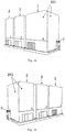
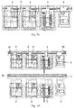
Fig. 1a is a side structural view of a sample analysis system according to the present invention; -
Fig. 1b is another side structural view of a sample analysis system according to the present invention; -
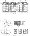
Fig. 1c is a top structural view of a sample analysis system according to the present invention; -
Fig. 2 is a view showing assembly and disassembly of a sample analysis system according to the present invention; -
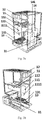
Fig. 3a is a side structural view of asample distribution node 1 in a sample analysis system according to the present invention; -
Fig. 3b is another side structural view of asample distribution node 1 in a sample analysis system according to the present invention; -
Fig. 3c is a top structural view of asample distribution node 1 in a sample analysis system according to the present invention; -
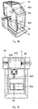
Fig. 4a is a side structural view of a reagent distribution andmeasurement node 2 in a sample analysis system according to the present invention; -
Fig. 4b is another side structural view of a reagent distribution andmeasurement node 2 in a sample analysis system according to the present invention; -
Fig. 4c is a top structural view of a reagent distribution andmeasurement node 2 in a sample analysis system according to the present invention; -
Fig. 5 shows an implementation of ameasurement module 23 in a sample analysis system according to the present invention; -
Fig. 6 shows another implementation of ameasurement module 23 in a sample analysis system according to the present invention; -
Fig. 7 shows still another implementation of ameasurement module 23 in a sample analysis system according to the present invention; -
Fig. 8a is a side structural view of aconsumables distribution node 5 in a sample analysis system according to the present invention; -
Fig. 8b is another side structural view of aconsumables distribution node 5 in a sample analysis system according to the present invention; -
Fig. 8c is a top structural view of aconsumables distribution node 5 in a sample analysis system according to the present invention; -
Fig. 9a is a side structural view of a sample analysis system including a cuvette distribution node according to the present invention; -
Fig. 9b is another side structural view of a sample analysis system including a cuvette distribution node according to the present invention; -
Fig. 9c is a top structural view of a sample analysis system including a cuvette distribution node according to the present invention; -
Fig. 10 is a top structural view of a sample analysis system having anintegrated rail device 3 according to the present invention; -
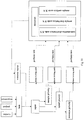
Fig. 11 is a diagram showing the control loop of a control method for a sample analysis system according to the present invention; and -
Fig. 12 is a view showing the node combination and the expansion of a sample analysis system according to the present invention. - In order to make the objectives, technical solutions and advantages of the present invention more apparent, the present invention will be further described in detail below with reference to the accompanying drawings and embodiments. It should be understood that the specific embodiments described herein are only intended to explain the present invention, and not to limit the present invention.
- In the present invention, different distributed sample analysis systems can be assembled from multiple expandable independent sample distribution nodes and reagent distribution and measurement nodes that are freely combined via a rail device under control of a control device.
- In order to explain the technical solutions of the present invention, description will be made below with specific embodiments.
- As show in
Figs. 1a, 1b , and1c , which are side and top structural views of a distributed sample analysis device mentioned above, a distributed sample analysis system according to the present invention includes: - a control device, a
rail device 3 for carrying cuvettes under control of the control device; - at least one independent
sample distribution node 1 arranged on therail device 3 for distributing samples to the cuvettes, the independentsample distribution node 1 being used for sample aspiration, transfer, and discharge; and - at least two independent reagent distribution and
measurement nodes 2 arranged on therail device 3 for distributing test reagents to the cuvettes and measuring the mixture liquid in the cuvettes, the independent reagent distribution andmeasurement nodes 2 being used for reagent aspiration, transfer, and discharge and reagent-sample mixture liquid measurement; the cuvettes being used for containing the sample and the reagent and signal measurement. - Referring to
Figs. 2 ,3a ,3b , and3c , in whichFig. 2 is a view showing assembly and disassembly of said sample analysis system according to the present invention andFigs. 3a, 3b , and3c are side and top views showing the implementation of saidsample distribution node 1 including a cuvette distribution module, said distributed sample analysis system can be specifically formed by onesample distribution node 1 including acuvette distribution module 14 and two reagent distribution andmeasurement nodes 2 that are detachably assembled and combined via rails 3. The manner of assembly and disassembly is shown at A or B inFig. 2 . Thecuvette distribution module 14 of thesample distribution node 1 delivers a batch ofcuvettes 4 to thenode rail 31 of therail device 3. The samples are transferred into thecuvettes 4 by a sample transfer module of the sample distribution node, then transported to the location of the reagent distribution andmeasurement nodes 2 by therail device 3, and measured and analyzed in the reagent distribution andmeasurement nodes 2 thereafter. - The nodes described above are independent functional units under control of said control device. For example, when one reagent distribution and
measurement node 2 needs to be removed, the part of thenode rail 32 can be reserved, without influencing the normal use of the sample analysis system, thereby facilitating maintenance. Alternatively, thenode rail 32 and the reagent distribution andmeasurement node 2 can be detached and removed together, and the remaining nodes can be stilled assembled and used. Also, new nodes can be added. In this way, free combination and efficient expansion of said sample analysis system is achieved. - In said sample analysis system, multiple
sample distribution nodes 1 and reagent distribution andmeasurement nodes 2 can be selected according to a combination rule. Said control device controls the node rail corresponding to these selected nodes to have the nodes assembled onto therail device 3 so as to communicate the individual nodes, or controls a certain node to be detached and removed from therail device 3. Therail device 3 includes multiple node rails that may constitute an integrated synchronized motion structure or a dividable structure consisting of free assembly and combination. According to different combination rules, thesample distribution nodes 1 and reagent distribution andmeasurement nodes 2 can be added and arranged onto therail device 3 for expansion, so as to obtain different sample analysis systems. The combination rules include speed priority principle, sample priority principle, resource priority principle, or the like. - Further, said sample analysis system has concurrency. That is, combination of a
sample distribution node 1 with a reagent distribution andmeasurement node 2 provides a basic measurement function of the analysis system. The reagent distribution and measurement node and sample distribution node beyond the basic measurement function combination constitute concurrent operation nodes. Under coordination by the control system, in the case that the reagent distribution andmeasurement node 2 andsample distribution node 1 beyond the basic measurement function combination are in the failure mode or the halt mode, said basic measurement function can still realize the sample analysis process. For example, in a sample analysis system with a basic measurement function consisting of onesample distribution node 1 combined with one reagent distribution andmeasurement node 2, if thesample distribution node 1 has a fast sample distribution speed, then the number of the reagent distribution andmeasurement nodes 2 can be increased as appropriate (e.g., to two) and these nodes perform measurement concurrently under control of the control system. That is, samples can be distributed to the reagent distribution andmeasurement nodes 2 successively for concurrent testing, thereby improving the testing efficiency. If one of the reagent distribution andmeasurement nodes 2 fails or halls, then the remaining nodes can continue to operate and realize the corresponding analysis. The concurrency of the sample analysis system may not influence the normal operation of the overall system, thereby facilitating maintenance and repairs. - As shown in
Figs, 3a, 3b , and3c , saidsample distribution node 1 includes: a sample distribution control device; a sample distribution device connected to the sample distribution control device for aspiration, transfer, and discharge of the sample to the cuvette in the current node under control of the sample distribution control device; and a sample distributionnode fixing frame 12 for fixing various portions of the sample distribution node to an independent structure. - Said sample distribution device further includes a
node rail module 31, a firstcuvette distribution module 14, asample transfer module 11, and asample loading region 13. - An aspiration and
discharge component 111 on thesample transfer module 11 aspirates a sample from a sample tube on thesample rack 131 in thesample loading region 13. Then through cooperation of therail 112 and thesample transfer module 11, the aspiration anddischarge component 111 is moved to the location of thecuvette 4 on thenode rail module 31, and the sample liquid is discharged to thecuvette 4. - In this embodiment, said aspiration and
discharge component 111 includes, without limitation, a quantitative liquid aspiration and discharge component driven by pneumatic, electric, or hydraulic actuation. The structure of thesample aspiration component 1111 may be a tubular structure like a sample probe, a sample tube, or the like capable of quick sample aspiration. - The
node rail module 31 is used for transportation of thecuvettes 4. Thecuvettes 4 may be placed directly on the rail and transported by the rail through mechanical driving such as fixation fitting, friction fitting, convex-concave structure fitting, or the like. In the case that thecuvettes 4 are placed directly on the rail, the cuvettes are preferably in the form of a cuvette row. Said rail has a mechanical design including, without limitation, a belt, a gear, a screw, or the like, for transmission movement. In some further possible embodiments, thecuvettes 4 may alternatively be placed on thenode rail 31 by loading thecuvettes 4 onto thevehicle 34 arranged on thenode rail 31. Thevehicle 34 has a solid structure that can receive thecuvette 4. - The sample distribution
node fixing frame 12 is used for fixing various modules and components integrated in thesample distribution node 1. The overallsample distribution node 1 has anindependent panel 121 fixed thereto (refer toFig. 1a ) to form a relatively independent functional structure and facilitate combination with other nodes. - The
sample loading region 13 serves as an input region for samples to facilitate transportation of samples to other nodes via thenode rail 31. The samples are directly placed manually in thesample loading region 13, or fed into thesample loading region 13 via an automated motion mechanism (a mechanism other than the rail). Said samples may be distributed to a container directly from a blood collecting tube, manually, or in an automated manner in advance. - The first
cuvette distribution module 14 is used for deliveringcuvettes 4 quickly.Numerous cuvettes 4 are stored in acuvette feeding mechanism 141, then thecuvettes 4 are loaded out of order into aslideway 142, and thereafter thecuvettes 4 arrive at acuvette tray mechanism 143 under gravity. Thereafter, agripper mechanism 144 grips and loadsempty cuvettes 4 onto thenode rail module 31. In this way, thecuvettes 4 can be output in batch and in order, thereby improving the efficiency of cuvette delivery. - In this embodiment, the
gripper mechanism 144 drives agripper structure 1442 in movement through adriving component 1441 into an opened or closed status, so as to mate with thecuvettes 4, thereby improving the gripping efficiency. - As shown in
Figs. 4a ,4b, and 4c , which are the side and top views showing an implementation of the reagent distribution andmeasurement node 2. The reagent distribution andmeasurement node 2 includes: a reagent distribution and measurement control device, a reagent distribution and measurement device connected to the reagent distribution and measurement control device for aspiration, transfer, and discharge of the reagent to thecuvette 4 in the current node for measurement under control of the reagent distribution and measurement control device; and a reagent distribution and measurementnode fixing frame 24 for fixing various portions of the reagent distribution and measurement node to an independent structure. - The reagent distribution and measurement device further includes a
node rail module 32, areagent distribution module 21, ameasurement module 23, and acuvette transfer module 22. Agripper mechanism 221 on thecuvette transfer module 22 grips acuvette 4 loaded with a sample from thenode rail 32. Thecuvette 4 is transferred to anincubation module 25 in the reagent distribution andmeasurement node 2 by amotion mechanism 222. Then the aspiration anddischarge component 211 on thereagent distribution module 21 aspirates analysis reagent from thereagent storage module 26. The aspiration anddischarge component 211 is moved by amotion mechanism 212 to the location of thecuvette 4 on theincubation module 25 and discharges the aspirated reagent into thecuvette 4. A blending mechanism blends the liquid in thecuvette 4 evenly. Thereafter, thecuvette 4 loaded with the mixture liquid of the reagent and the sample is moved to themeasurement module 23 through movement of thegripper mechanism 221 and the sample analysis process is completed in themeasurement module 23. Then thecuvette 4 is transported by thenode rail module 32 to the next functional node. - Said
gripper mechanism 221 and aspiration anddischarge component 211 include, without limitation, components driven by pneumatic, electric, or hydraulic actuation. The structure of the aspiration anddischarge component 211 for reagent aspiration may be a tubular structure such as a reagent probe, a reagent tube, or the like. The structure for reagent aspiration includes, without limitation, one enabling aspiration through movement in a pipeline (one with multiple ports, i.e., the liquid transfer process including aspiration through one end and discharge through the other), and one enabling aspiration through reagent probe aspiration and reagent probe displacement (the reagent probe is connected with a spatial motion rail and a transmission mechanism, i.e., the movement in which the reagent probe aspirates reagent, the reagent is spatially moved to a designated location, and the liquid is discharged). The motion of the reagent may be a motion such as planer motion, rotation around an axis center over a certain radius, planar and vertical three-dimensional motions, and rotation around an axis center over a certain radius combined with vertical motion, or the like. Thegripper mechanism 221 may further be connected with a spatial motion mechanism, including, without limitation, a mechanical structure of motion such as planar motion, vertical motion, three-dimensional motion, rotation, or the like, for bringing along the cuvette gripped by the gripper mechanism and transferring it to the measurement location on the reagent distribution and measurement node. - Said reagent distribution and measurement node further includes a blending mechanism with blending function, specifically, one capable of driving the liquid in movement of blending, including, without limitation, blending through bubbling, agitation, ultrasound, vibration, or the like.
- Said reagent distribution and measurement node further includes a reagent storage module for storage of analysis reagent. In the case of a reagent of biological material, the reagent storage structure may further include an assembly associated with cooling for cooling the reagent atmosphere in the storage structure down to various temperature ranges, which can provide various levels of temperature regulation based on well-known techniques in the industry. The reagent storage module in the reagent distribution and measurement node can operate in two storage modes, i.e. cooling storage and non-cooling storage, so as to provide storage for analysis reagents with different characteristics.
- The reagent distribution and measurement
node fixing frame 24 is used for fixing the functional components and modules in the reagent distribution and measurement node. The reagent distribution and measurementnode fixing frame 24 may further have an independent panel 241 (referring toFig. 1b ) connected to its surface that is mated thereto to form a relatively independent functional device and also facilitates combination with other nodes. - The rail of said
node rail module 32 has a mechanical design for transmission of movement, including, without limitation, a belt, a gear, a screw, or the like. - Said
cuvette 4 is a container made of solid material, including, without limitation, plastic, glass, quartz, metal, or the like, that cannot be easily broken and can be recycled conveniently. Thecuvette 4 as the container for a sample may be in the unit of one, or may be in the form of a cuvette row of several connected cuvettes. - The
measurement module 23 may utilize a measurement principle including optical measurement, electrical measurement, acoustical measurement, magnetic measurement, or the like. Examples of the specific testing principle are shown inFigs. 5-7 . - For example, in the case of optical measurement, as shown at part A in
Fig. 5 , after the spectrum emitted from alight source 2311 passes through afilter 2312, only light of a specific wavelength arrives at and passes through acuvette 2313 loaded with the sample-reagent mixture liquid. Then, the optical signal passing through thecuvette 2313 is collected by aphotodiode 2314 and converted into an electric signal. Then the electric signal is collected by apre-processing circuit 2315 and anAD collection circuit 2316 and processed by amicroprocessor 2317 and converted into a displayable digital signal. - At part B in
Fig. 5 , the sample reacts with the reagent in thecuvette 2321 to generate a particular optical signal, which is collected by a photomultiplier tube (PMT) 2322 and converted into a detectable electric signal. Then the electric signal is collected by apre-processing circuit 2323 and anAD collection circuit 2324 and processed by amicroprocessor 2325 and converted into a displayable digital signal. - As shown in
Fig. 6 , in the case of electrical measurement, ananode 2332 and acathode 2333 are inserted into thecuvette 2331. The sample reacts with the reagent to generate an electric signal that can be collected by 2334. The collected electric signal is preliminarily processed by asignal conditioning circuit 2335 to condition the signal intensity. Then the electric signal is collected by anAD collection circuit 2336 and converted by a micro-processor 2337 into a displayable digital signal. - For example, in the case of magnetic measurement, referring to
Fig. 7 , a fixed magnetic field is provided bymagnetic bars cuvette 2341 of a curved track configuration, inducing themagnetic beads 2344 in thecuvette 2341 into reciprocation. Meanwhile, a magnetic signal is generated after power-on of amagnetic pot 2345 on one side of the cuvette, and can be received by amagnetic pot 2346 on the other side, transmitted over a circuit, and converted into an electric signal. When the liquid in thecuvette 2341 becomes clear, themagnetic beads 2344 reciprocate at the same speed so that the electric signal finally formed is displayed on the display end as a regular wave band. As the sample reacts with the reagent in thecuvette 2341, the solution starts to become cloudy. Themagnetic beads 2344 are subject to resistance that becomes increasingly greater during the reciprocation and move at a gradually lower speed or even stop, so that the wave band displayed on the display end starts to have smaller amplitude until it becomes a straight line. The concentration of the sample can be analyzed through the variation tendency of the wave band. - As shown in
Figs. 8a ,8b, and 8c , which are side and top views of acuvette distribution node 5 included in said sample analysis system, thecuvette distribution node 5 can be used for providingcuvettes 4 to other nodes in said sample analysis system. Thecuvette distribution node 5 includes: a cuvette distribution control device; a cuvette distribution device for loading cuvettes onto the rail device in order under control of the cuvette distribution control device; and a cuvette distributionnode fixing frame 52 for fixing various portions of the cuvette distribution node to an independent structure. - The cuvette distribution device further includes a second
cuvette distribution module 51 and anode rail module 33.Numerous cuvettes 4 are stored in acuvette feeding mechanism 511 of the secondcuvette distribution module 51, then thecuvettes 4 are loaded out of order into a slideway 142 (a non-bidirectional rail) by thecuvette feeding mechanism 511, and thereafter thecuvettes 4 arrive at acuvette tray mechanism 513 under gravity. Thereafter, thegripper mechanism 514 grips and loadsempty cuvettes 4 onto thenode rail module 33. Anindependent panel 521 may further be fixed to the surface of the fixingframe 52 for fixing components and modules. - Refer to
Figs. 9a, 9b , and9c , which are side and top structural views of a sample analysis system including a cuvette distribution node in this embodiment. Said sample analysis system may include acuvette distribution node 5, asample distribution node 1, and two sample analysis nodes 2 (i.e., reagent distribution and measurement nodes 2) that are combined and assembled detachably via therail device 3.Numerous cuvettes 4 are provided to therail 3 by thecuvette distribution node 5 and then transmitted over therail 3. Thecuvettes 4 arrive at thesample distribution node 1, then samples are loaded into thecuvettes 4 by thesample transfer module 11 in thesample analysis node 1, and finally arrive at thesample analysis node 2 for measurement and analysis. - In some other alternative embodiments, in said sample analysis system, the
rail device 3 may also be a single rail of connected segments. As shown inFig. 10 , thecuvette distribution node 5, thesample distribution node 1, and the reagent distribution andmeasurement nodes 2 are assembled and combined on therail device 3. Thegears 35 at both sides of therail device 3 drive thevehicle 34 to transmit thecuvettes 4 from thecuvette distribution node 5 to other nodes. - As the
sample distribution node 1, the reagent distribution andmeasurement nodes 2, and thecuvette distribution node 5 described above are all functional units of an independent frame structure, the nodes can be removed and the part of the node rail can be reserved based on different combination rules, without influencing the normal use of the remaining parts of the sample analysis system, thereby facilitating maintenance. Alternatively, the part of the rail and the node can be detached and removed together, and the remaining nodes can still be assembled via the node rail and used, and new nodes can be added, thereby realizing free combination and efficient expansion of said distributed sample analysis system into different sample analysis systems. - Another implementation of the present invention provides a control method for a sample analysis system for control of said sample analysis system, including the steps of:
- acquiring a task type and the status of the nodes;
- determining a combination rule of the nodes based on the task type and the status of the nodes; and
- performing sample analysis based on the combination rule.
- Further, the step of performing sample analysis based on the combination rule includes:
- planning a testing path including selection and combination of the nodes and rails based on the combination rule; and
- performing sample analysis based on the testing path.
- First, the task type input into said sample analysis system, including task number, task project, and task requirement, is acquired; and at the same time, the status of the resource node of said sample analysis system, i.e., the utilization of the resource node, whether there is any abnormal resource, or the like is acquired, the resource node including the sample distribution node, the reagent distribution and measurement node, and the cuvette distribution node.
- Then the combination rule is determined based on the acquired task type and the status of the recourse node. That is, the type and number of the nodes is selected based on the task type, then a node that is not abnormal and not occupied is selected based on the status of the resource node, so as to satisfy the requirements of the task. The combination rule includes sample priority principle, speed priority principle, resource priority principle, or the like.
- Finally, sample analysis is performed based on said combination rule, that is, the selected nodes are assembled in the order of sample analysis via the rail device, so as to obtain a testing path of the sample analysis system. Then sample analysis is performed through cooperation of the nodes via movement of the rail.
- The control process flow of the overall sample analysis system is shown in
Fig. 11 . Different task types are distinguished based on the task number, task project, and task requirement. Then, in combination with the status of each resource node, an optimum control mode is selected from control modes corresponding to the three combination rules to complete the sample analysis task. In all the three modes, the path and sequence in which the samples run in the nodes can be selected. For example, if the task type is an emergency task, then the sample priority control mode is enabled. That is, both the node and the rail load, offload, and measure the vehicle in which the priority sample is situated in priority. If the task involves a large number of samples, then the speed priority mode is selected, so that the node, rail, and vehicle are distributed to an idle node with the highest efficiency, thereby avoiding resource waste and consequently achieving the optimum sample distribution and analysis speed. If, however, a small number of samples are to be measured, or the different nodes in the measurement system select different measurement projects, then the node priority mode is preferably selected, so that analysis and testing at a designated node can be completed, thereby significantly improving the analysis efficiency. - Moreover, as said sample analysis system described above has high freedom and high expendability, the control method for said sample analysis system can control a plurality of the
sample distribution node 1, thesample analysis node 2, and thecuvette distribution node 5 to be freely assembled via therail 3 to form a distributed structure. For example, as shown inFig. 12 , in the distributed sample analysis system, in addition to onecuvette distribution node 5, onesample distribution node 1, and twosample analysis nodes 2, multiplesample distribution nodes 1 can be added so as to improve the efficiency of sample aspiration. Also, multiplesample analysis nodes 2 of the same or different analysis functions can be further added, so as to fulfill efficient analysis of multiple samples or simultaneous analysis of different samples. In the overall analysis system, multiple nodes with different or same functions can be freely expanded through extension or assembly of the rails. The control method for said sample analysis system controls the number and combination manner of the sample distribution node and the reagent distribution and measurement node in said sample analysis system and adjusts the multiple presented coordination manners through combination and connection, without departing from the scope of variation of the present solution. - Another implementation of the present invention provides a sample analysis method, including the steps of:
- distributing, by the cuvette distribution node, cuvettes onto the rail device and conveying the cuvettes to the sample distribution nodes by way of the rail device communicating the multiple nodes;
- distributing, by the sample distribution node, the samples to the cuvettes;
- conveying the cuvettes to the reagent distribution and measurement nodes through movement of the rail device;
- distributing, by the reagent distribution and measurement nodes, the analysis reagent to the cuvettes, and performing measurement and analysis on the sample-reagent mixture liquid in the cuvettes; and
- finishing analysis or repeating the steps described above.
- Cuvettes are distributed to the rail device by at least one cuvette distribution node and transported to at least one sample distribution node of an independent frame structure via the rail, and then samples are distributed to the cuvettes. The test reagent is distributed to the cuvettes by the multiple reagent distribution and measurement nodes of independent frame structures, and measurements and analysis of the reagent-sample mixture liquid are performed in sequence by these reagent distribution and measurement nodes. The rail communicating various nodes is used for transfer of the cuvettes between various nodes and transportation of the cuvettes between various nodes. A control system is provided to control the cuvette distribution node, the sample distribution node, and the reagent distribution and measurement nodes to cooperate with the rails.
- The distributed sample analysis system provided by the present invention uses cuvettes as the medium and employs multiple relatively independent sample distribution nodes and multiple relatively independent reagent distribution and measurement nodes. The control method for the sample analysis system controls the nodes to be freely combined and connected via rails, so that the constraint of physical cooperation relationship between sample distribution components and sample analysis components in conventional instruments are eliminated, thereby providing a fully automated analysis system with small size, high efficiency, high freedom, and high expandability. Besides, the nodes can be freely added and freely combined and connected to form analysis systems with various speeds and analysis functions, thereby significantly improving the utilization of the structural components in the instrument and enabling easy installation and maintenance.
- Described above are only the preferred embodiments of the present invention that are not intended to limit the present invention. Any modification, equivalent replacement, and improvement made within the spirit and principle of the present invention shall fall in the protection scope of the present invention.
Claims (15)
- A sample analysis system, comprising:a control device;a rail device for carrying cuvettes under control of the control device;at least one independent sample distribution node arranged on the rail device for distributing samples to the cuvettes, the independent sample distribution node being used for sample aspiration, transfer, and discharge; andat least two independent reagent distribution and measurement nodes arranged on the rail device for distributing test reagents to the cuvettes and measuring mixture liquid in the cuvettes, the independent reagent distribution and measurement nodes being used for reagent aspiration, transfer, and discharge and reagent-sample mixture liquid measurement;the cuvettes being used for containing the samples and reagent and signal measurement.
- The sample analysis system of claim 1, wherein the rail device includes multiple node rails corresponding to the sample distribution node and the reagent distribution and measurement nodes for communication between individual nodes, the multiple node rails constituting an integrated synchronized motion structure or a dividable structure consisting of free assembly and combination.
- The sample analysis system of claim 2, wherein the sample distribution node comprises:a sample distribution control device;a sample distribution device for aspiration, transfer, and discharge of a sample to a cuvette in a current node under control of the sample distribution control device; anda sample distribution node fixing frame for fixing various portions of the sample distribution node to an independent structure.
- The sample analysis system of claim 3, wherein the reagent distribution and measurement node comprises:a reagent distribution and measurement control device;a reagent distribution and measurement device for aspiration, transfer, and discharge of the reagent to the cuvette in the current node for measurement under control of the reagent distribution and measurement control device; anda reagent distribution and measurement node fixing frame for fixing various portions of the reagent distribution and measurement node to an independent structure.
- The sample analysis system of claim 4, wherein the analysis system has concurrency, combination of a sample distribution node with a reagent distribution and measurement node provides a basic measurement function of the analysis system; the reagent distribution and measurement node and sample distribution node beyond the basic measurement function combination constitute concurrent operation nodes; and
under coordination by the control system, in the case that the reagent distribution and measurement node and sample distribution node beyond the basic measurement function combination are in a failure mode or a halt mode, said basic measurement function can still realize a sample analysis process. - The sample analysis system of claim 5, wherein the sample distribution node and reagent distribution and measurement nodes are combined according to different combination rules and arranged on the rail device to constitute different sample analysis systems, and these sample analysis systems can be expanded by adding the sample distribution and reagent distribution and measurement nodes and configuring the rail device.
- The sample analysis system of claim 6, wherein the sample analysis system further comprises:
a cuvette distribution node for providing cuvettes to other nodes in the sample analysis system. - The sample analysis system of claim 7, wherein the cuvette distribution node further comprises:a cuvette distribution control device;a cuvette distribution device for loading the cuvettes onto the rail device in order under control of the cuvette distribution control device; anda cuvette distribution node fixing frame for fixing various portions of the cuvette distribution node to an independent structure.
- The sample analysis system of claim 4, wherein the reagent distribution and measurement node further comprises a blending mechanism for blending the sample, the reagent, and the reagent-sample mixture liquid evenly.
- The sample analysis system of claim 9, wherein the reagent distribution and measurement node further comprises a gripper mechanism and a motion mechanism, the gripper mechanism being used for gripping the cuvette on the rail or in a vehicle, the motion mechanism being used for bringing and transferring the cuvette gripped by the gripper mechanism to a measurement location at the reagent distribution and measurement node.
- The sample analysis system of claim 10, wherein the reagent distribution and measurement node further comprises a reagent storage module for storing analysis reagent.
- The sample analysis system of claim 1, wherein each of the cuvettes is a container made of a solid material to serve as a carrier for sample and reagent distribution, transfer, and measurement.
- A control method for a sample analysis system for controlling the sample analysis system of any one of claims 1 to 12, comprising steps of:acquiring a task type and status of nodes;determining a combination rule for the nodes based on the task type and the status of the nodes; andperforming sample analysis based on the combination rule.
- The control method for a sample analysis system of claim 13, wherein the step of performing sample analysis based on the combination rule comprises:planning a testing path including selection and combination of the nodes and rails based on the combination rule; andperforming sample analysis based on the testing path.
- A sample analysis method for the sample analysis system of any one of claims 1 to 12, comprising the steps of:distributing, by the cuvette distribution node, cuvettes onto the rail device and conveying the cuvettes to the sample distribution node by way of the rail device communicating multiple nodes;distributing, by the sample distribution node, the samples to the cuvettes;conveying the cuvettes to the reagent distribution and measurement nodes through movement of the rail device;distributing, by the reagent distribution and measurement nodes, the analysis reagent to the cuvettes, and performing measurement and analysis on the sample-reagent mixture liquid in the cuvettes; andfinishing analysis or repeating the above steps.
Applications Claiming Priority (2)
| Application Number | Priority Date | Filing Date | Title |
|---|---|---|---|
| CN201910490798.5A CN110208554B (en) | 2019-06-06 | 2019-06-06 | Sample analysis system, control method thereof and sample analysis method |
| PCT/CN2019/091379 WO2020243988A1 (en) | 2019-06-06 | 2019-06-14 | Sample analysis system and control method therefor, and sample analysis method |
Publications (3)
| Publication Number | Publication Date |
|---|---|
| EP3916395A1 true EP3916395A1 (en) | 2021-12-01 |
| EP3916395A4 EP3916395A4 (en) | 2022-10-26 |
| EP3916395B1 EP3916395B1 (en) | 2024-08-07 |
Family
ID=67791261
Family Applications (1)
| Application Number | Title | Priority Date | Filing Date |
|---|---|---|---|
| EP19931868.4A Active EP3916395B1 (en) | 2019-06-06 | 2019-06-14 | Sample analysis system and control method therefor, and sample analysis method |
Country Status (6)
| Country | Link |
|---|---|
| US (1) | US12007401B2 (en) |
| EP (1) | EP3916395B1 (en) |
| CN (1) | CN110208554B (en) |
| ES (1) | ES2989425T3 (en) |
| PL (1) | PL3916395T3 (en) |
| WO (1) | WO2020243988A1 (en) |
Families Citing this family (7)
| Publication number | Priority date | Publication date | Assignee | Title |
|---|---|---|---|---|
| CN110617804A (en) * | 2019-09-25 | 2019-12-27 | 浙江海洋大学 | Marine ecological environment detection system and method based on remote sensing technology |
| CN113109579B (en) * | 2020-01-10 | 2025-06-17 | 深圳迈瑞生物医疗电子股份有限公司 | A sample analysis system and sample scheduling method thereof |
| CN112326981A (en) * | 2020-09-30 | 2021-02-05 | 迈克医疗电子有限公司 | Sample analysis apparatus and sample analysis method |
| CN112378887A (en) * | 2020-11-16 | 2021-02-19 | 深圳传世生物医疗有限公司 | Analysis method of blood coagulation analyzer and blood coagulation analyzer |
| US20260002954A1 (en) * | 2022-06-27 | 2026-01-01 | Beckman Coulter, Inc. | Sample handling arrangement |
| US20250306053A1 (en) * | 2024-03-31 | 2025-10-02 | Shenzhen Mindray Bio-Medical Electronics Co., Ltd. | Sample analysis module and sample analysis system |
| WO2025226748A1 (en) * | 2024-04-23 | 2025-10-30 | Siemens Healthcare Diagnostics Inc. | Method and system for design and maintenance of complex, multimodule, random access, clinical laboratory automation systems |
Family Cites Families (23)
| Publication number | Priority date | Publication date | Assignee | Title |
|---|---|---|---|---|
| JP3930977B2 (en) * | 1998-07-31 | 2007-06-13 | 株式会社日立製作所 | Sample processing system |
| JP3175729B2 (en) * | 1999-03-10 | 2001-06-11 | 株式会社日立製作所 | Automatic analyzer |
| JP2002048800A (en) * | 2000-07-31 | 2002-02-15 | Olympus Optical Co Ltd | Automatic analyzer |
| US6808304B2 (en) * | 2002-08-27 | 2004-10-26 | Dade Behring Inc. | Method for mixing liquid samples using a linear oscillation stroke |
| EP1582874B1 (en) * | 2004-03-31 | 2008-07-09 | Roche Diagnostics GmbH | Modular analysing apparatus |
| ATE391918T1 (en) * | 2004-11-25 | 2008-04-15 | Hoffmann La Roche | DEVICE FOR ANALYZING SAMPLES |
| JP5372678B2 (en) * | 2009-09-17 | 2013-12-18 | シスメックス株式会社 | Sample processing equipment |
| JP5738616B2 (en) | 2011-02-03 | 2015-06-24 | シスメックス株式会社 | Sample analysis system, sample analyzer, and sample analysis method |
| JP5787574B2 (en) * | 2011-03-30 | 2015-09-30 | シスメックス株式会社 | Sample analysis system |
| US9039992B2 (en) * | 2011-06-06 | 2015-05-26 | Abbott Laboratories | Apparatus for closed tube sampling and open tube sampling for automated clinical analyzers |
| JP5789441B2 (en) * | 2011-08-01 | 2015-10-07 | 株式会社日立ハイテクノロジーズ | Genetic testing system |
| EP2755037B1 (en) * | 2011-09-05 | 2024-12-25 | Hitachi High-Tech Corporation | Automatic analysis device |
| US20140107953A1 (en) * | 2012-10-16 | 2014-04-17 | Beckman Coulter, Inc. | Container fill level detection |
| US10139422B2 (en) * | 2013-01-09 | 2018-11-27 | Siemens Healthcare Diagnostics Inc. | Throughput optimizing reagent distribution |
| WO2015126839A1 (en) * | 2014-02-19 | 2015-08-27 | Siemens Healthcare Diagnostics Inc. | Mother daughter tube carrier for aliquoters |
| US9835640B2 (en) * | 2015-02-13 | 2017-12-05 | Abbott Laboratories | Automated storage modules for diagnostic analyzer liquids and related systems and methods |
| CN107532979B (en) | 2015-06-22 | 2020-12-22 | 深圳迈瑞生物医疗电子股份有限公司 | Sample analysis device and control method thereof |
| EP3391058A4 (en) * | 2015-12-18 | 2019-08-28 | Abbott Laboratories | Systems and methods for automated analysis |
| JP6850545B2 (en) * | 2016-03-31 | 2021-03-31 | シスメックス株式会社 | Specimen analysis system |
| CN107850611B (en) | 2016-04-15 | 2021-11-05 | 深圳迈瑞生物医疗电子股份有限公司 | Sample rack transport device, sample analysis equipment and sample analysis system |
| CN105974894B (en) * | 2016-04-25 | 2018-05-29 | 温冬梅 | Automatic reagent supply system of automatic assembly line of medical laboratory |
| JP7048217B2 (en) | 2017-04-28 | 2022-04-05 | シスメックス株式会社 | Transport equipment, transport method and sample analysis system |
| LU100530B1 (en) * | 2017-11-29 | 2019-06-12 | Stratec Biomedical Ag | Diagnostic analyzer systems |
-
2019
- 2019-06-06 CN CN201910490798.5A patent/CN110208554B/en active Active
- 2019-06-14 EP EP19931868.4A patent/EP3916395B1/en active Active
- 2019-06-14 PL PL19931868.4T patent/PL3916395T3/en unknown
- 2019-06-14 ES ES19931868T patent/ES2989425T3/en active Active
- 2019-06-14 WO PCT/CN2019/091379 patent/WO2020243988A1/en not_active Ceased
-
2021
- 2021-04-26 US US17/241,034 patent/US12007401B2/en active Active
Also Published As
| Publication number | Publication date |
|---|---|
| WO2020243988A1 (en) | 2020-12-10 |
| US12007401B2 (en) | 2024-06-11 |
| PL3916395T3 (en) | 2024-11-18 |
| ES2989425T3 (en) | 2024-11-26 |
| CN110208554A (en) | 2019-09-06 |
| EP3916395A4 (en) | 2022-10-26 |
| CN110208554B (en) | 2021-05-11 |
| EP3916395B1 (en) | 2024-08-07 |
| US20210247410A1 (en) | 2021-08-12 |
Similar Documents
| Publication | Publication Date | Title |
|---|---|---|
| US12007401B2 (en) | Sample analysis system and control method for the same and sample analysis method | |
| EP3299794A1 (en) | Automated scheduler for laboratory equipment | |
| CN102565437B (en) | Sample analyzer | |
| JP4637897B2 (en) | Device for supplying whole blood analyzer | |
| US20160320422A1 (en) | Automated analyzer for clinical laboratory | |
| EP1881329A2 (en) | Method for scheduling samples in a combinational clinical analyzer | |
| EP1199569A2 (en) | Sample analysis system | |
| EP1460431A2 (en) | Automatic analyzer | |
| JP2008203279A (en) | Automatic measurement cartridge | |
| CN112415214A (en) | Sample rack handling device, detection system, submission method and computer readable medium | |
| WO2018155190A1 (en) | Automated analyzer | |
| US8211313B2 (en) | System for processing magnetic particles | |
| WO2020152991A1 (en) | Automatic analysis system and specimen conveying method | |
| CN102341711B (en) | Reaction container holder and analyzer | |
| CN113272653A (en) | Automatic analyzer, automatic analysis system, and automatic analysis method for specimen | |
| EP4109105B1 (en) | AUTOMATIC ANALYSIS DEVICE | |
| JP6789036B2 (en) | Automatic analyzer and laboratory information system | |
| JP2022543145A (en) | Walk-away time visualization method and system | |
| WO2010004789A1 (en) | Autoanalyzer | |
| CN112567249A (en) | Automatic analysis device and method thereof | |
| CN112166327A (en) | Automatic analyzer and sample transfer method | |
| US20260126371A1 (en) | Multimodal analytical system for analyzing biological fluids | |
| EP4286856A1 (en) | Sample rack manipulation device, testing system and testing method and computer-readable medium | |
| CN120721993A (en) | Sample analysis module and sample analysis system | |
| CN117368511A (en) | Sample analysis device and sample dilution method |
Legal Events
| Date | Code | Title | Description |
|---|---|---|---|
| STAA | Information on the status of an ep patent application or granted ep patent |
Free format text: STATUS: THE INTERNATIONAL PUBLICATION HAS BEEN MADE |
|
| PUAI | Public reference made under article 153(3) epc to a published international application that has entered the european phase |
Free format text: ORIGINAL CODE: 0009012 |
|
| STAA | Information on the status of an ep patent application or granted ep patent |
Free format text: STATUS: REQUEST FOR EXAMINATION WAS MADE |
|
| 17P | Request for examination filed |
Effective date: 20210827 |
|
| AK | Designated contracting states |
Kind code of ref document: A1 Designated state(s): AL AT BE BG CH CY CZ DE DK EE ES FI FR GB GR HR HU IE IS IT LI LT LU LV MC MK MT NL NO PL PT RO RS SE SI SK SM TR |
|
| DAV | Request for validation of the european patent (deleted) | ||
| DAX | Request for extension of the european patent (deleted) | ||
| A4 | Supplementary search report drawn up and despatched |
Effective date: 20220923 |
|
| RIC1 | Information provided on ipc code assigned before grant |
Ipc: G01N 35/10 20060101ALI20220919BHEP Ipc: G01N 35/00 20060101ALI20220919BHEP Ipc: G01N 35/04 20060101ALI20220919BHEP Ipc: G01N 35/02 20060101AFI20220919BHEP |
|
| GRAP | Despatch of communication of intention to grant a patent |
Free format text: ORIGINAL CODE: EPIDOSNIGR1 |
|
| STAA | Information on the status of an ep patent application or granted ep patent |
Free format text: STATUS: GRANT OF PATENT IS INTENDED |
|
| INTG | Intention to grant announced |
Effective date: 20240220 |
|
| GRAS | Grant fee paid |
Free format text: ORIGINAL CODE: EPIDOSNIGR3 |
|
| GRAA | (expected) grant |
Free format text: ORIGINAL CODE: 0009210 |
|
| STAA | Information on the status of an ep patent application or granted ep patent |
Free format text: STATUS: THE PATENT HAS BEEN GRANTED |
|
| AK | Designated contracting states |
Kind code of ref document: B1 Designated state(s): AL AT BE BG CH CY CZ DE DK EE ES FI FR GB GR HR HU IE IS IT LI LT LU LV MC MK MT NL NO PL PT RO RS SE SI SK SM TR |
|
| REG | Reference to a national code |
Ref country code: GB Ref legal event code: FG4D |
|
| REG | Reference to a national code |
Ref country code: CH Ref legal event code: EP |
|
| REG | Reference to a national code |
Ref country code: IE Ref legal event code: FG4D |
|
| REG | Reference to a national code |
Ref country code: DE Ref legal event code: R096 Ref document number: 602019056825 Country of ref document: DE |
|
| REG | Reference to a national code |
Ref country code: LT Ref legal event code: MG9D |
|
| REG | Reference to a national code |
Ref country code: ES Ref legal event code: FG2A Ref document number: 2989425 Country of ref document: ES Kind code of ref document: T3 Effective date: 20241126 |
|
| REG | Reference to a national code |
Ref country code: NL Ref legal event code: MP Effective date: 20240807 |
|
| PG25 | Lapsed in a contracting state [announced via postgrant information from national office to epo] |
Ref country code: NO Free format text: LAPSE BECAUSE OF FAILURE TO SUBMIT A TRANSLATION OF THE DESCRIPTION OR TO PAY THE FEE WITHIN THE PRESCRIBED TIME-LIMIT Effective date: 20241107 |
|
| REG | Reference to a national code |
Ref country code: AT Ref legal event code: MK05 Ref document number: 1711503 Country of ref document: AT Kind code of ref document: T Effective date: 20240807 |
|
| PG25 | Lapsed in a contracting state [announced via postgrant information from national office to epo] |
Ref country code: NL Free format text: LAPSE BECAUSE OF FAILURE TO SUBMIT A TRANSLATION OF THE DESCRIPTION OR TO PAY THE FEE WITHIN THE PRESCRIBED TIME-LIMIT Effective date: 20240807 Ref country code: GR Free format text: LAPSE BECAUSE OF FAILURE TO SUBMIT A TRANSLATION OF THE DESCRIPTION OR TO PAY THE FEE WITHIN THE PRESCRIBED TIME-LIMIT Effective date: 20241108 Ref country code: PT Free format text: LAPSE BECAUSE OF FAILURE TO SUBMIT A TRANSLATION OF THE DESCRIPTION OR TO PAY THE FEE WITHIN THE PRESCRIBED TIME-LIMIT Effective date: 20241209 Ref country code: FI Free format text: LAPSE BECAUSE OF FAILURE TO SUBMIT A TRANSLATION OF THE DESCRIPTION OR TO PAY THE FEE WITHIN THE PRESCRIBED TIME-LIMIT Effective date: 20240807 |
|
| PG25 | Lapsed in a contracting state [announced via postgrant information from national office to epo] |
Ref country code: BG Free format text: LAPSE BECAUSE OF FAILURE TO SUBMIT A TRANSLATION OF THE DESCRIPTION OR TO PAY THE FEE WITHIN THE PRESCRIBED TIME-LIMIT Effective date: 20240807 |
|
| PG25 | Lapsed in a contracting state [announced via postgrant information from national office to epo] |
Ref country code: LV Free format text: LAPSE BECAUSE OF FAILURE TO SUBMIT A TRANSLATION OF THE DESCRIPTION OR TO PAY THE FEE WITHIN THE PRESCRIBED TIME-LIMIT Effective date: 20240807 |
|
| PG25 | Lapsed in a contracting state [announced via postgrant information from national office to epo] |
Ref country code: AT Free format text: LAPSE BECAUSE OF FAILURE TO SUBMIT A TRANSLATION OF THE DESCRIPTION OR TO PAY THE FEE WITHIN THE PRESCRIBED TIME-LIMIT Effective date: 20240807 Ref country code: IS Free format text: LAPSE BECAUSE OF FAILURE TO SUBMIT A TRANSLATION OF THE DESCRIPTION OR TO PAY THE FEE WITHIN THE PRESCRIBED TIME-LIMIT Effective date: 20241207 |
|
| PG25 | Lapsed in a contracting state [announced via postgrant information from national office to epo] |
Ref country code: HR Free format text: LAPSE BECAUSE OF FAILURE TO SUBMIT A TRANSLATION OF THE DESCRIPTION OR TO PAY THE FEE WITHIN THE PRESCRIBED TIME-LIMIT Effective date: 20240807 |
|
| PG25 | Lapsed in a contracting state [announced via postgrant information from national office to epo] |
Ref country code: RS Free format text: LAPSE BECAUSE OF FAILURE TO SUBMIT A TRANSLATION OF THE DESCRIPTION OR TO PAY THE FEE WITHIN THE PRESCRIBED TIME-LIMIT Effective date: 20241107 |
|
| PG25 | Lapsed in a contracting state [announced via postgrant information from national office to epo] |
Ref country code: RS Free format text: LAPSE BECAUSE OF FAILURE TO SUBMIT A TRANSLATION OF THE DESCRIPTION OR TO PAY THE FEE WITHIN THE PRESCRIBED TIME-LIMIT Effective date: 20241107 Ref country code: PT Free format text: LAPSE BECAUSE OF FAILURE TO SUBMIT A TRANSLATION OF THE DESCRIPTION OR TO PAY THE FEE WITHIN THE PRESCRIBED TIME-LIMIT Effective date: 20241209 Ref country code: NO Free format text: LAPSE BECAUSE OF FAILURE TO SUBMIT A TRANSLATION OF THE DESCRIPTION OR TO PAY THE FEE WITHIN THE PRESCRIBED TIME-LIMIT Effective date: 20241107 Ref country code: NL Free format text: LAPSE BECAUSE OF FAILURE TO SUBMIT A TRANSLATION OF THE DESCRIPTION OR TO PAY THE FEE WITHIN THE PRESCRIBED TIME-LIMIT Effective date: 20240807 Ref country code: LV Free format text: LAPSE BECAUSE OF FAILURE TO SUBMIT A TRANSLATION OF THE DESCRIPTION OR TO PAY THE FEE WITHIN THE PRESCRIBED TIME-LIMIT Effective date: 20240807 Ref country code: IS Free format text: LAPSE BECAUSE OF FAILURE TO SUBMIT A TRANSLATION OF THE DESCRIPTION OR TO PAY THE FEE WITHIN THE PRESCRIBED TIME-LIMIT Effective date: 20241207 Ref country code: HR Free format text: LAPSE BECAUSE OF FAILURE TO SUBMIT A TRANSLATION OF THE DESCRIPTION OR TO PAY THE FEE WITHIN THE PRESCRIBED TIME-LIMIT Effective date: 20240807 Ref country code: GR Free format text: LAPSE BECAUSE OF FAILURE TO SUBMIT A TRANSLATION OF THE DESCRIPTION OR TO PAY THE FEE WITHIN THE PRESCRIBED TIME-LIMIT Effective date: 20241108 Ref country code: FI Free format text: LAPSE BECAUSE OF FAILURE TO SUBMIT A TRANSLATION OF THE DESCRIPTION OR TO PAY THE FEE WITHIN THE PRESCRIBED TIME-LIMIT Effective date: 20240807 Ref country code: BG Free format text: LAPSE BECAUSE OF FAILURE TO SUBMIT A TRANSLATION OF THE DESCRIPTION OR TO PAY THE FEE WITHIN THE PRESCRIBED TIME-LIMIT Effective date: 20240807 Ref country code: AT Free format text: LAPSE BECAUSE OF FAILURE TO SUBMIT A TRANSLATION OF THE DESCRIPTION OR TO PAY THE FEE WITHIN THE PRESCRIBED TIME-LIMIT Effective date: 20240807 |
|
| PG25 | Lapsed in a contracting state [announced via postgrant information from national office to epo] |
Ref country code: RO Free format text: LAPSE BECAUSE OF FAILURE TO SUBMIT A TRANSLATION OF THE DESCRIPTION OR TO PAY THE FEE WITHIN THE PRESCRIBED TIME-LIMIT Effective date: 20240807 Ref country code: SM Free format text: LAPSE BECAUSE OF FAILURE TO SUBMIT A TRANSLATION OF THE DESCRIPTION OR TO PAY THE FEE WITHIN THE PRESCRIBED TIME-LIMIT Effective date: 20240807 Ref country code: DK Free format text: LAPSE BECAUSE OF FAILURE TO SUBMIT A TRANSLATION OF THE DESCRIPTION OR TO PAY THE FEE WITHIN THE PRESCRIBED TIME-LIMIT Effective date: 20240807 |
|
| PG25 | Lapsed in a contracting state [announced via postgrant information from national office to epo] |
Ref country code: EE Free format text: LAPSE BECAUSE OF FAILURE TO SUBMIT A TRANSLATION OF THE DESCRIPTION OR TO PAY THE FEE WITHIN THE PRESCRIBED TIME-LIMIT Effective date: 20240807 |
|
| PG25 | Lapsed in a contracting state [announced via postgrant information from national office to epo] |
Ref country code: CZ Free format text: LAPSE BECAUSE OF FAILURE TO SUBMIT A TRANSLATION OF THE DESCRIPTION OR TO PAY THE FEE WITHIN THE PRESCRIBED TIME-LIMIT Effective date: 20240807 |
|
| PG25 | Lapsed in a contracting state [announced via postgrant information from national office to epo] |
Ref country code: SK Free format text: LAPSE BECAUSE OF FAILURE TO SUBMIT A TRANSLATION OF THE DESCRIPTION OR TO PAY THE FEE WITHIN THE PRESCRIBED TIME-LIMIT Effective date: 20240807 |
|
| REG | Reference to a national code |
Ref country code: DE Ref legal event code: R097 Ref document number: 602019056825 Country of ref document: DE |
|
| PLBE | No opposition filed within time limit |
Free format text: ORIGINAL CODE: 0009261 |
|
| STAA | Information on the status of an ep patent application or granted ep patent |
Free format text: STATUS: NO OPPOSITION FILED WITHIN TIME LIMIT |
|
| PGFP | Annual fee paid to national office [announced via postgrant information from national office to epo] |
Ref country code: DE Payment date: 20250618 Year of fee payment: 7 Ref country code: PL Payment date: 20250521 Year of fee payment: 7 |
|
| PGFP | Annual fee paid to national office [announced via postgrant information from national office to epo] |
Ref country code: GB Payment date: 20250618 Year of fee payment: 7 |
|
| 26N | No opposition filed |
Effective date: 20250508 |
|
| PGFP | Annual fee paid to national office [announced via postgrant information from national office to epo] |
Ref country code: FR Payment date: 20250627 Year of fee payment: 7 |
|
| PGFP | Annual fee paid to national office [announced via postgrant information from national office to epo] |
Ref country code: TR Payment date: 20250610 Year of fee payment: 7 |
|
| PG25 | Lapsed in a contracting state [announced via postgrant information from national office to epo] |
Ref country code: SE Free format text: LAPSE BECAUSE OF FAILURE TO SUBMIT A TRANSLATION OF THE DESCRIPTION OR TO PAY THE FEE WITHIN THE PRESCRIBED TIME-LIMIT Effective date: 20240807 |
|
| PGFP | Annual fee paid to national office [announced via postgrant information from national office to epo] |
Ref country code: ES Payment date: 20250731 Year of fee payment: 7 |
|
| REG | Reference to a national code |
Ref country code: CH Ref legal event code: H13 Free format text: ST27 STATUS EVENT CODE: U-0-0-H10-H13 (AS PROVIDED BY THE NATIONAL OFFICE) Effective date: 20260127 |
|
| PG25 | Lapsed in a contracting state [announced via postgrant information from national office to epo] |
Ref country code: MC Free format text: LAPSE BECAUSE OF FAILURE TO SUBMIT A TRANSLATION OF THE DESCRIPTION OR TO PAY THE FEE WITHIN THE PRESCRIBED TIME-LIMIT Effective date: 20240807 |
|
| PG25 | Lapsed in a contracting state [announced via postgrant information from national office to epo] |
Ref country code: LU Free format text: LAPSE BECAUSE OF NON-PAYMENT OF DUE FEES Effective date: 20250614 |
|
| REG | Reference to a national code |
Ref country code: BE Ref legal event code: MM Effective date: 20250630 |
|
| PG25 | Lapsed in a contracting state [announced via postgrant information from national office to epo] |
Ref country code: IE Free format text: LAPSE BECAUSE OF NON-PAYMENT OF DUE FEES Effective date: 20250614 |
|
| PG25 | Lapsed in a contracting state [announced via postgrant information from national office to epo] |
Ref country code: BE Free format text: LAPSE BECAUSE OF NON-PAYMENT OF DUE FEES Effective date: 20250630 Ref country code: IT Free format text: LAPSE BECAUSE OF NON-PAYMENT OF DUE FEES Effective date: 20250614 |
|
| PG25 | Lapsed in a contracting state [announced via postgrant information from national office to epo] |
Ref country code: CH Free format text: LAPSE BECAUSE OF NON-PAYMENT OF DUE FEES Effective date: 20250630 |