EP3916225A2 - Vakuumpumpe - Google Patents
Vakuumpumpe Download PDFInfo
- Publication number
- EP3916225A2 EP3916225A2 EP21199985.9A EP21199985A EP3916225A2 EP 3916225 A2 EP3916225 A2 EP 3916225A2 EP 21199985 A EP21199985 A EP 21199985A EP 3916225 A2 EP3916225 A2 EP 3916225A2
- Authority
- EP
- European Patent Office
- Prior art keywords
- pump
- chamber
- vacuum pump
- ballast
- gas
- Prior art date
- Legal status (The legal status is an assumption and is not a legal conclusion. Google has not performed a legal analysis and makes no representation as to the accuracy of the status listed.)
- Granted
Links
Images

Classifications
-
- F—MECHANICAL ENGINEERING; LIGHTING; HEATING; WEAPONS; BLASTING
- F04—POSITIVE - DISPLACEMENT MACHINES FOR LIQUIDS; PUMPS FOR LIQUIDS OR ELASTIC FLUIDS
- F04B—POSITIVE-DISPLACEMENT MACHINES FOR LIQUIDS; PUMPS
- F04B37/00—Pumps having pertinent characteristics not provided for in, or of interest apart from, groups F04B25/00 - F04B35/00
- F04B37/10—Pumps having pertinent characteristics not provided for in, or of interest apart from, groups F04B25/00 - F04B35/00 for special use
- F04B37/14—Pumps having pertinent characteristics not provided for in, or of interest apart from, groups F04B25/00 - F04B35/00 for special use to obtain high vacuum
-
- F—MECHANICAL ENGINEERING; LIGHTING; HEATING; WEAPONS; BLASTING
- F04—POSITIVE - DISPLACEMENT MACHINES FOR LIQUIDS; PUMPS FOR LIQUIDS OR ELASTIC FLUIDS
- F04B—POSITIVE-DISPLACEMENT MACHINES FOR LIQUIDS; PUMPS
- F04B39/00—Component parts, details, or accessories, of pumps or pumping systems specially adapted for elastic fluids, not otherwise provided for in, or of interest apart from, groups F04B25/00 - F04B37/00
- F04B39/16—Filtration; Moisture separation
-
- F—MECHANICAL ENGINEERING; LIGHTING; HEATING; WEAPONS; BLASTING
- F04—POSITIVE - DISPLACEMENT MACHINES FOR LIQUIDS; PUMPS FOR LIQUIDS OR ELASTIC FLUIDS
- F04B—POSITIVE-DISPLACEMENT MACHINES FOR LIQUIDS; PUMPS
- F04B49/00—Control, e.g. of pump delivery, or pump pressure of, or safety measures for, machines, pumps, or pumping installations, not otherwise provided for, or of interest apart from, groups F04B1/00 - F04B47/00
- F04B49/06—Control using electricity
- F04B49/065—Control using electricity and making use of computers
-
- F—MECHANICAL ENGINEERING; LIGHTING; HEATING; WEAPONS; BLASTING
- F04—POSITIVE - DISPLACEMENT MACHINES FOR LIQUIDS; PUMPS FOR LIQUIDS OR ELASTIC FLUIDS
- F04B—POSITIVE-DISPLACEMENT MACHINES FOR LIQUIDS; PUMPS
- F04B2205/00—Fluid parameters
- F04B2205/07—Pressure difference over the pump
-
- F—MECHANICAL ENGINEERING; LIGHTING; HEATING; WEAPONS; BLASTING
- F04—POSITIVE - DISPLACEMENT MACHINES FOR LIQUIDS; PUMPS FOR LIQUIDS OR ELASTIC FLUIDS
- F04B—POSITIVE-DISPLACEMENT MACHINES FOR LIQUIDS; PUMPS
- F04B2205/00—Fluid parameters
- F04B2205/09—Flow through the pump
-
- F—MECHANICAL ENGINEERING; LIGHTING; HEATING; WEAPONS; BLASTING
- F04—POSITIVE - DISPLACEMENT MACHINES FOR LIQUIDS; PUMPS FOR LIQUIDS OR ELASTIC FLUIDS
- F04B—POSITIVE-DISPLACEMENT MACHINES FOR LIQUIDS; PUMPS
- F04B2207/00—External parameters
- F04B2207/04—Settings
- F04B2207/043—Settings of time
Definitions
- the present invention relates to a vacuum pump having a pump chamber and an inlet connected to the pump chamber and an outlet connected to the pump chamber.
- a gas to be conveyed can be conveyed from the inlet to the outlet in the pump chamber, in particular by means of a pump body.
- a chamber to be evacuated can be connected to the inlet.
- the vacuum pump is designed for feeding a gas ballast into the pump chamber.
- a chamber connected to the inlet of the vacuum pump When operating vacuum pumps, a chamber connected to the inlet of the vacuum pump is usually evacuated.
- the vacuum pump sucks in gas present in the chamber at the inlet and pumps this gas to be conveyed through the outlet, whereby the chamber is evacuated.
- the gas initially present in the chamber is compressed more and more within the vacuum pump as it approaches the outlet, so that any moisture contained in the gas to be conveyed condenses and is reflected in the area of the outlet. It is undesirable for (condensation) water to remain in the pump chamber.
- ballast In order to remove the moisture or the water from the pump chamber again, it is known to use a gas ballast, i.e. to pump a ballast gas through the pump chamber of the vacuum pump so that the ballast gas or the gas ballast removes the water from the pump chamber.
- the object on which the invention is based is therefore to specify a vacuum pump which prevents water or moisture from remaining in the pump chamber.
- the vacuum pump according to the invention comprises a control device which is designed to calculate a ballast pumping duration, which indicates how long gas ballast must be pumped in order to pump out water that is present or suspected in the pumping chamber, the control device also being designed to supply the gas ballast for a supply duration effect, the feed time depending on the calculated ballast pumping time.
- the invention is based on the knowledge that the ballast pumping time can be calculated (or at least estimated using reasonable assumptions) so that a ballast pumping time can be specified for the respective operating parameters or the respective operating state, which ensures that water present or suspected within the pumping chamber the ballast pumping time can be pumped out completely.
- the calculation can also be based on assumptions so that an assumed amount of water can be calculated.
- the calculated amount of water can preferably be selected such that the calculated amount of water usually exceeds the amount of water actually present in the pump chamber.
- the ballast pumping time calculated from the calculated amount of water can then be used to introduce gas ballast into the pumping chamber for the supply time.
- variables eg the amount of water
- the calculations and / or determinations of variables (eg the amount of water) described herein can also be estimates, since the calculations are based at least in part on assumptions and / or measured variables (with inaccuracies).
- the feed duration can in particular correspond to the ballast pump duration or also differ from it, as will be explained later.
- the vacuum pump is in operation during the supply period, conveys the supplied gas ballast in the direction of the outlet and releases it through the outlet.
- the gas ballast also called ballast gas or additional gas load
- the gas ballast can be a different gas than the gas to be conveyed, for example the gas ballast can come from another source (not from the chamber to be evacuated), have a different temperature and / or a different humidity and the like.
- An inert gas or air for example, can be provided as gas ballast.
- the gas ballast can in particular have a low relative humidity (for example less than 40% or less than 30% or 20%).
- the gas ballast can also be, for example, dry nitrogen. Gases with low humidity can take up water present in the pump chamber and lead to the water being discharged from the pump chamber.
- the control device can in particular be designed to automatically bring about the supply of the gas ballast, as will be explained in more detail later.
- the control device can also output a signal, whereby an operator is then instructed to manually open a valve or the like.
- the control device is designed to calculate the amount of water present in the pump chamber.
- the amount of water can in principle comprise evaporated and / or condensed water. Accordingly, instead of the amount of water, one could also speak of the amount of moisture.
- the amount of water present in the pump chamber is determined based on the volume of a chamber connected to the inlet.
- the volume of the chamber is preferably determined on the basis of a previous pump-out time, the pumping speed of the pump and / or a pressure difference over the pump-down time.
- the amount of water present in the pump chamber can therefore be determined based on the volume of the chamber, it being assumed that all of the water from the volume of the chamber remains in the pump chamber.
- the volume of the chamber can, for example, be a maximum volume of a chamber to be connected, as specified by the manufacturer. This maximum volume can also be used if a smaller chamber is connected if necessary.
- the volume of the chamber can therefore be permanently stored in the control device, for example. This ensures that the amount of water in the pump chamber is not assumed to be too small.
- the control unit can record the previous pump-out time.
- the pumping speed of the pump (unit m 3 / h) is inherent in the pump and can accordingly also be stored in the control unit.
- the pumping speed of the pump can also be determined by measuring the power consumed by the vacuum pump. In this way, chambers of different sizes can be recognized and different pumping times can be taken into account. If a larger chamber volume is calculated than the chamber volume permanently stored in the control unit, the larger chamber volume can be used.
- the gas to be conveyed in the connected chamber has the maximum temperature permitted for the vacuum pump and / or the maximum moisture permitted for the vacuum pump. It is also preferably assumed that all of the moisture in the gas to be pumped or in the gas (already) pumped remains as water in the pump chamber.
- the maximum temperature and the maximum (relative) humidity of the gas in the chamber are also defined for a respective vacuum pump and are therefore known. In order to ensure that the water is completely pumped out of the pump chamber, it can thus be assumed that the gas in the chamber actually has the maximum permissible humidity and temperature for the vacuum pump.
- the maximum temperature can be 40 ° C and the maximum relative humidity 80% for the gas to be conveyed.
- air can absorb a maximum of 50 g / m 3 of water. If it is now assumed that the chamber has a volume of 200 liters, then there are 200 l 8 g of water in these. The amount of water in the pump chamber is assumed to be 8 g after such a chamber has been evacuated.
- the control device is designed to calculate the ballast pump duration from the water vapor capacity of the vacuum pump and the amount of water in the pump chamber.
- the water vapor capacity is the largest amount of water that a vacuum pump can continuously suck in and convey in the form of water vapor per unit of time under the ambient conditions of 20 ° C and 1,013 hPa.
- the water vapor capacity can be given in g / h, for example.
- the water vapor capacity is therefore a variable for a water vapor mass flow.
- the water vapor capacity indicates the highest water vapor pressure at which a vacuum pump can continuously suck in and convey pure water vapor under normal ambient conditions (20 ° C, 1,013 hPa).
- q pV ballast is the gas ballast flow
- S is the pumping speed of the vacuum pump
- p S is the saturation vapor pressure of the water vapor at exhaust gas temperature (i.e. at the outlet)
- p A is the partial pressure of the water vapor when the gas ballast is fed in
- p 0 is the atmospheric pressure of the environment
- ⁇ is dimensionless Correction factor that takes into account the fact that a pressure greater than atmospheric pressure is required to open any outlet valve that may be present.
- ⁇ can assume a value of 1.1.
- the water vapor tolerance has the dimension of a pressure and is usually given in hPa . If the pressures p mentioned above are not measured, maximum values can be assumed which are still just permissible for the vacuum pump and which lead to a maximum amount of water or ballast pumping time or to a low water vapor tolerance.
- the water vapor capacity increases as the partial pressure of the water vapor in the gas ballast decreases and also increases at a higher temperature at the outlet, since the saturation vapor pressure of the water vapor then rises at the exhaust gas temperature.
- control device can be designed to determine the water vapor capacity of the vacuum pump based on the humidity of the gas ballast and / or based on the partial pressure of the water vapor in the gas ballast and / or based on the temperature at the outlet. For a low humidity or a low partial pressure of the water vapor in the gas ballast or a high one Temperature at the outlet can be determined accordingly a higher water vapor capacity.
- the humidity of the gas ballast, the partial pressure of the water vapor in the gas ballast and / or the temperature at the outlet can each be determined by measurement or by specifying set values.
- the supply duration corresponds to between 70% and 110%, preferably between 80% and 100%, particularly preferably between 90% and 100% of the ballast pump duration.
- the supply duration is in particular the period of time in which gas ballast is actually supplied and pumped through the outlet by the vacuum pump in order to discharge the amount of water from the pump chamber.
- the feeding time can correspond exactly to the calculated ballast pumping time.
- the supply duration is selected to be longer or shorter than the ballast pump duration. Due to the worst-case assumptions, it can be assumed, for example, even with a reduction to 70%, that all the water can be removed from the pump chamber during the supply period.
- a gas ballast valve of the vacuum pump can be open during the supply period. While the gas ballast valve is open, the chamber to be evacuated can in particular be separated off in order to avoid a subsequent pressure increase in the chamber.
- control device is designed to cause the opening of a gas ballast valve and thus the supply of the gas ballast, wherein the gas ballast valve is preferably opened when the pressure falls below a predetermined pressure at the inlet.
- the control unit can therefore open the gas ballast valve automatically.
- the control device can also instruct an operator by means of a signal to open the gas ballast valve.
- the gas ballast valve can then be opened or the supply period can begin when the chamber is sufficiently evacuated and the pressure at the inlet falls below, for example, 10 mbar or 1 mbar.
- the gas ballast is ambient air, the ambient air having the maximum temperature and / or humidity permitted for the (environment of the) vacuum pump (e.g. 40 ° C and 30% relative humidity).
- control device is designed to close the inlet while the gas ballast is being fed in or, in principle, to separate the chamber from the pump chamber.
- closing the inlet while the gas ballast is being fed in only a slight change in the minimum pressure in the chamber can be achieved.
- Such an operation can also be referred to as clocked operation.
- the inlet can be open while gas ballast is being fed in at the same time (gas ballast valve open).
- gas ballast valve open it is then possible to continuously calculate how much new moisture has been introduced from the chamber into the pumping space and what amount of water has been pumped out.
- the calculated ballast pumping time can then be extended during operation, so that the feed time can also be extended.
- a channel for supplying the gas ballast opens into the pump chamber, the channel preferably between the inlet and the outlet opens into the pump chamber and is in particular arranged closer to the outlet than to the inlet.
- the channel is therefore a separate access to the pump chamber for the inlet and outlet.
- the channel can be located closer to the outlet, since the higher pressure causes the moisture to precipitate or condense there.
- the vacuum pump is a scroll pump.
- the vacuum pump can have two parallel chambers which compress the gas to be conveyed in the direction of the interior or in the direction of the outlet of the vacuum pump.
- the vacuum pump can have two intermingled spirals which, by moving in opposite directions, compress and convey the gas to be conveyed and also the supplied gas ballast in the direction of the outlet.
- the pump body can accordingly comprise one or more of the spirals.
- a gas ballast bore connected to the gas ballast valve can be positioned in such a way that the gas ballast can be applied to at least one of the two parallel chambers or both chambers at a time.
- the vacuum pump can also be a rotary vane vacuum pump, preferably an oil-lubricated rotary vane vacuum pump.
- the pump body can be formed by a rotor shaft and at least one rotary valve.
- the vacuum pump can be designed in one or more stages, for example in two stages.
- Another object of the invention is a method for operating a vacuum pump with a pumping chamber, in which a ballast pumping time is calculated, which indicates how long gas ballast has to be pumped in order to pump out water present or suspected in the pumping chamber, and a supply of the gas ballast is effected for a supply duration, the supply duration depending on the calculated ballast pumping duration.
- the invention also relates to a control device for a vacuum pump with a pumping chamber, the control device being designed to calculate a ballast pumping duration that indicates how long gas ballast must be pumped in order to pump out water that is present or suspected in the pump chamber, the control device also being designed to cause a supply of the gas ballast for a supply duration, the supply duration depending on the calculated ballast pump duration.
- the control device is in particular the control device described above in connection with the vacuum pump.
- the invention also relates to a vacuum pump system with a vacuum pump as described herein, the vacuum pump system comprising a chamber to be evacuated which is coupled to the inlet of the vacuum pump.
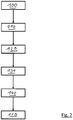
- Fig. 1 shows a vacuum pump 10, which is designed as a scroll pump.
- a pump chamber 12 is arranged in the vacuum pump 10, in which a gas to be conveyed is pumped or conveyed from an inlet 16 to an outlet 18 by means of a spiral-shaped pump body 14 (not explicitly shown).
- a chamber 20 to be evacuated is connected to the inlet 16, in which, in the present example, 200 liters of air are present at 40 ° C. and 80% humidity.
- a pressure sensor 22 is arranged at the inlet 16 of the vacuum pump 10 and determines the pressure of the air flowing in from the chamber 20 via the inlet 16.
- the pressure sensor 22 is coupled to a control device 24 of the vacuum pump 10 and transmits its measurement results to the control device 24.
- the control device 24 also receives measurement results from a temperature sensor 26, which is arranged at the outlet 18.
- a gas ballast valve 28 which can introduce ambient air 30 between the inlet 16 and the outlet 18 into the pump chamber 12, is also arranged on the vacuum pump 10.
- the control unit 24 is coupled to the gas ballast valve 28 in order to be able to open the gas ballast valve 28.
- control device 24 is connected to a power measurement 32, the power measurement 32 recording the power currently required by the vacuum pump 10, so that the control device 24 can draw conclusions about the respective pumping speed and the pumping duration / pumping time of the vacuum pump 10.
- step 100 the pump down time begins.
- the pressure sensor 22 initially determines the initial pressure at the inlet 16 or in the chamber 20 and the vacuum pump 10 begins pumping the gas to be conveyed out of the chamber 20.
- the chamber 20 is further evacuated, with the gas ballast valve 28 is closed. Evacuating the chamber causes water to condense out of the chamber 20 in the pump chamber 12. If the pressure in the chamber 20 or at the inlet 16 falls below a predetermined minimum pressure, the pump-out time ends with step 120 determined.
- the temperature of the pump at the outlet 18 can be measured via the temperature sensor 26.
- control device 24 can also determine the pumping speed with which the vacuum pump 10 was operated for how long. In this way, the control device 24 can determine the volume of the chamber 20 connected to the inlet 16 or the volume pumped out. The pressure difference between steps 100 and 120 is also used for this determination.
- control device 24 calculates in step 130 the (in particular assumed) amount of water that is potentially present in the pump chamber 12.
- the ballast pump duration is then calculated from the amount of water in step 140 with the aid of the water vapor capacity of the vacuum pump. If the water vapor capacity of the vacuum pump 10 is, for example, 44.7 g / h and the amount of water was calculated to be 8 g, the ballast pump duration is 11 minutes.
- step 150 the control unit 24 then opens the gas ballast valve 28 and closes the inlet 16.
- gas ballast in this case
- Example ambient air is pumped in order to remove the amount of water from the pump chamber 12.
- the duration of the pumping of gas ballast i.e. the supply duration, can be selected in accordance with the ballast pump duration of 11 minutes, so that the pumping of gas ballast is ended after 11 minutes. At this point in time, it can be assumed that all of the water or all of the moisture has been removed from the pump chamber 12. It is then possible to begin anew at step 100.
- worst-case assumptions provide the security that practically all of the water is removed from the pump chamber during the supply period of the gas ballast.
Landscapes
- Engineering & Computer Science (AREA)
- Mechanical Engineering (AREA)
- General Engineering & Computer Science (AREA)
- Computer Hardware Design (AREA)
- Applications Or Details Of Rotary Compressors (AREA)
- Compressors, Vaccum Pumps And Other Relevant Systems (AREA)
Abstract
Description
- Die vorliegende Erfindung betrifft eine Vakuumpumpe mit einem Pumpraum und einem mit dem Pumpraum verbundenen Einlass sowie einem mit dem Pumpraum verbundenen Auslass. Dabei ist in dem Pumpraum, insbesondere mittels eines Pumpkörpers, ein zu förderndes Gas von dem Einlass zu dem Auslass förderbar. An den Einlass ist eine zu evakuierende Kammer anschließbar. Zudem ist die Vakuumpumpe für das Zuführen eines Gasballasts in den Pumpraum ausgebildet.
- Beim Betrieb von Vakuumpumpen wird üblicherweise eine an den Einlass der Vakuumpumpe angeschlossene Kammer evakuiert. Dabei saugt die Vakuumpumpe in der Kammer vorhandenes Gas am Einlass an und pumpt dieses zu fördernde Gas durch den Auslass, wodurch die Kammer evakuiert wird. Das zunächst in der Kammer vorhandene Gas wird innerhalb der Vakuumpumpe beim Annähern an den Auslass immer weiter komprimiert, sodass eventuell in dem zu fördernden Gas enthaltene Feuchtigkeit kondensiert und sich im Bereich des Auslasses niederschlägt. Ein Verbleib von (Kondens-)Wasser im Pumpraum ist unerwünscht.
- Um die Feuchtigkeit bzw. das Wasser aus dem Pumpraum wieder zu entfernen, ist es bekannt, einen Gasballast zu verwenden, das heißt ein Ballastgas durch den Pumpraum der Vakuumpumpe zu pumpen, sodass das Ballastgas bzw. der Gasballast das Wasser aus dem Pumpraum entfernt.
- Bei herkömmlichen Verfahren kann das Problem bestehen, dass nicht sichergestellt ist, dass tatsächlich keine Feuchtigkeit mehr im Pumpraum der Vakuumpumpe vorhanden ist.
- Es ist daher die der Erfindung zugrunde liegende Aufgabe, eine Vakuumpumpe anzugeben, welche ein Verbleiben von Wasser bzw. Feuchtigkeit im Pumpraum verhindert.
- Diese Aufgabe wird durch eine Vakuumpumpe gemäß Anspruch 1 gelöst.
- Die erfindungsgemäße Vakuumpumpe umfasst ein Steuergerät, welches ausgebildet ist, eine Ballastpumpdauer zu berechnen, die angibt, wie lange Gasballast gepumpt werden muss, um im Pumpraum vorhandenes oder vermutetes Wasser auszupumpen, wobei das Steuergerät ferner ausgebildet ist, ein Zuführen des Gasballasts für eine Zuführdauer zu bewirken, wobei die Zuführdauer von der berechneten Ballastpumpdauer abhängt.
- Die Erfindung geht von der Erkenntnis aus, dass die Ballastpumpdauer berechnet (oder durch vernünftige Annahmen zumindest abgeschätzt) werden kann, sodass für die jeweiligen Betriebsparameter bzw. den jeweiligen Betriebszustand eine Ballastpumpdauer angegeben werden kann, die sicherstellt, dass im Pumpraum vorhandenes oder vermutetes Wasser innerhalb der Ballastpumpdauer vollständig ausgepumpt werden kann. Bei der Berechnung kann auch von Annahmen ausgegangen werden, sodass eine vermutete Wassermenge berechnet werden kann. Die berechnete Wassermenge kann bevorzugt so gewählt sein, dass die berechnete Wassermenge üblicherweise die tatsächlich in dem Pumpraum vorhandene Wassermange übersteigt. Die aus der berechneten Wassermange berechnete Ballastpumpdauer kann dann herangezogen werden, um für die Zuführdauer Gasballast in den Pumpraum einzubringen.
- Die hierin beschriebenen Berechnungen und/oder Bestimmungen von Größen (z.B. der Wassermenge) können jeweils auch Schätzungen sein, da die Berechnungen zumindest zum Teil auf Annahmen und/oder Messgrößen (mit Ungenauigkeiten) basieren.
- Die Zuführdauer kann insbesondere der Ballastpumpdauer entsprechen oder sich auch von ihr unterscheiden, wie später noch ausgeführt wird.
- Es versteht sich, dass die Vakuumpumpe während der Zuführdauer in Betrieb ist, den zugeführten Gasballast in Richtung des Auslasses fördert und durch den Auslass abgibt.
- Durch den Gasballast (auch Ballastgas oder zusätzliche Gaslast genannt) wird ein Spüleffekt bewirkt, der es ermöglicht, das im Pumpraum vorhandene Wasser durch den Auslass aus der Pumpe heraus zu befördern.
- Bei dem Gasballast kann es sich um ein anderes Gas als das zu fördernde Gas handeln, beispielsweise kann der Gasballast aus einer anderen Quelle (nicht aus der zu evakuierenden Kammer) stammen, eine andere Temperatur und/oder eine andere Luftfeuchtigkeit besitzen und dergleichen mehr. Als Gasballast kann z.B. ein Inertgas oder beispielsweise auch Luft vorgesehen sein. Der Gasballast kann insbesondere eine geringe relative Feuchte aufweisen (von beispielsweise weniger als 40 % oder weniger als 30 % oder 20 %). Insbesondere kann es sich bei dem Gasballast auch z.B. um trockenen Stickstoff handeln. Gase mit geringer Feuchte können dabei gut im Pumpraum vorhandenes Wasser aufnehmen und zu einem Austragen des Wassers aus dem Pumpraum führen.
- Das Steuergerät kann insbesondere ausgebildet sein, das Zuführen des Gasballasts automatisch zu bewirken, wie später noch genauer ausgeführt wird. Alternativ kann das Steuergerät auch ein Signal ausgeben, wodurch ein Bediener dann zu einem manuellen Öffnen eines Ventils oder dergleichen angeleitet wird.
- Vorteilhafte Weiterbildungen der Erfindung sind der Beschreibung, den Zeichnungen sowie den Unteransprüchen zu entnehmen.
- Gemäß einer ersten Ausführungsform ist das Steuergerät ausgebildet, die im Pumpraum vorhandene Wassermenge zu berechnen. Bei der Berechnung der vorhandenen Wassermenge kann die potentiell vorhandene Wassermenge bestimmt werden, die z.B. zum momentanen Zeitpunkt im Pumpraum vorliegt. Die Wassermenge kann grundsätzlich verdampftes und/oder kondensiertes Wasser umfassen. Dementsprechend könnte statt Wassermenge auch von Feuchtemenge gesprochen werden.
- Gemäß einer weiteren Ausführungsform wird die im Pumpraum vorhandene Wassermenge basierend auf dem Volumen einer an den Einlass angeschlossenen Kammer ermittelt. Bevorzugt wird das Volumen der Kammer anhand einer bisherigen Auspumpzeit, dem Saugvermögen der Pumpe und/oder einer Druckdifferenz über die Auspumpzeit ermittelt.
- Grundsätzlich kann also die im Pumpraum vorhandene Wassermenge basierend auf dem Volumen der Kammer ermittelt werden, wobei davon ausgegangen wird, dass sämtliches Wasser aus dem Volumen der Kammer im Pumpraum verbleibt. Das Volumen der Kammer kann beispielsweise ein vom Hersteller angegebenes Maximalvolumen einer anzuschließenden Kammer sein. Dieses Maximalvolumen kann auch dann verwendet werden, wenn gegebenenfalls eine kleinere Kammer angeschlossen wird. Das Volumen der Kammer kann also beispielsweise fest in dem Steuergerät hinterlegt sein. Auf diese Weise wird sichergestellt, dass die Wassermenge im Pumpraum nicht zu gering angenommen wird.
- Alternativ oder zusätzlich kann das Steuergerät das Kammervolumen VK auch über die Formel

- Gemäß einer weiteren Ausführungsform wird für die Ermittlung der im Pumpenraum vorhandenen Wassermenge angenommen, dass das zu fördernde Gas in der angeschlossenen Kammer die für die Vakuumpumpe maximal zugelassene Temperatur und/oder die für die Vakuumpumpe maximal zugelassene Feuchtigkeit aufweist. Bevorzugt wird ebenfalls angenommen, dass sämtliche Feuchtigkeit des zu fördernden Gases oder des (bereits) geförderten Gases als Wasser im Pumpraum zurückbleibt.
- Dass sämtliche Feuchtigkeit des zu fördernden oder schon geförderten Gases als Wasser im Pumpraum zurückbleibt, kann als Annahme sämtlichen hierin beschriebenen Ausführungsformen zugrundegelegt werden.
- Die maximale Temperatur und die maximale (relative) Feuchtigkeit des Gases in der Kammer sind für eine jeweilige Vakuumpumpe ebenfalls festgelegt und damit bekannt. Um ein vollständiges Auspumpen des Wassers aus dem Pumpraum sicherzustellen, kann somit angenommen werden, dass das Gas in der Kammer tatsächlich die maximal für die Vakuumpumpe zugelassene Feuchtigkeit und Temperatur aufweist.
- Beispielsweise kann die maximale Temperatur bei 40 °C und die maximale relative Luftfeuchtigkeit bei 80 % für das zu fördernde Gas liegen. Bei 40 °C kann Luft maximal 50 g/m3 Wasser aufnehmen. Wird nun davon ausgegangen, dass die Kammer ein Volumen von 200 Litern umfasst, so finden sich in diesen 200 I 8 g Wasser. Die Wassermenge im Pumpraum wird nach dem Evakuieren einer solchen Kammer folglich mit 8 g angenommen.
- Gemäß einer weiteren Ausführungsform ist das Steuergerät ausgebildet, aus der Wasserdampfkapazität der Vakuumpumpe und der Wassermenge im Pumpraum die Ballastpumpdauer zu berechnen. Die Wasserdampfkapazität ist die größte Wassermenge, die eine Vakuumpumpe je Zeiteinheit unter den Umgebungsbedingungen von 20 °C und 1.013 hPa in Form von Wasserdampf dauernd ansaugen und fördern kann. Die Wasserdampfkapazität kann beispielsweise in g/h angegeben werden. Bei der Wasserdampfkapazität handelt es sich also um eine Größe für einen Wasserdampf-Massenstrom. Die Wasserdampfkapazität kann insbesondere nach der Formel

- Die Wasserdampfkapazität gibt den höchsten Wasserdampfdruck an, bei dem eine Vakuumpumpe unter normalen Umgebungsbedingungen (20°C, 1.013 hPa) reinen Wasserdampf dauernd ansaugen und fördern kann.
- Die Wasserdampfverträglichkeit pw kann nach der Formel

- Die Wasserdampfkapazität steigt also mit geringer werdendem Partialdruck des Wasserdampfs im Gasballast und steigt ebenfalls bei einer höheren Temperatur am Auslass, da dann der Sättigungsdampfdruck des Wasserdampfs bei der Abgastemperatur steigt.
- Dementsprechend kann das Steuergerät ausgebildet sein, die Wasserdampfkapazität der Vakuumpumpe basierend auf der Feuchtigkeit des Gasballasts und/oder basierend auf dem Partialdruck des Wasserdampfs im Gasballast und/oder basierend auf der Temperatur am Auslass zu bestimmen. Für eine niedrige Feuchtigkeit bzw. einen niedrigen Partialdruck des Wasserdampfs im Gasballast oder eine hohe Temperatur am Auslass kann dementsprechend eine höhere Wasserdampfkapazität bestimmt werden. Die Feuchtigkeit des Gasballasts, der Partialdruck des Wasserdampfs im Gasballast und/oder die Temperatur am Auslass können jeweils durch Messung oder durch Vorgabe von eingestellten Werten bestimmt werden.
- Bei einer beispielhaften Vakuumpumpe kann sich eine Wasserdampfkapazität von z.B. 44,7 g/h ergeben. Wird nun davon ausgegangen (insbesondere in einer Worst-Case-Betrachtung), dass im Pumpraum eine Wassermenge von 8 g vorhanden ist, so ergibt sich eine Ballastpumpdauer von 11 min (8 g / 44,7 g/h = 11 min). Da es sich um eine Worst-Case-Betrachtung handelt, ist sichergestellt, dass nach Ablauf der Ballastpumpdauer tatsächlich die gesamte Wassermenge aus dem Pumpraum entfernt wurde.
- Gemäß einer weiteren Ausführungsform entspricht die Zuführdauer zwischen 70 % und 110 %, bevorzugt zwischen 80 % und 100 %, besonders bevorzugt zwischen 90 % und 100 % der Ballastpumpdauer. Die Zuführdauer ist insbesondere der Zeitraum, in welchem tatsächlich Gasballast zugeführt und von der Vakuumpumpe durch den Auslass gepumpt wird, um die Wassermenge aus dem Pumpraum auszutragen. Die Zuführdauer kann exakt der berechneten Ballastpumpdauer entsprechen. Es ist aber auch möglich, dass die Zuführdauer länger oder kürzer als die Ballastpumpdauer gewählt wird. Durch die Worst-Case-Annahmen kann beispielsweise auch bei einer Verkürzung auf 70 % davon ausgegangen werden, dass sämtliches Wasser in der Zuführdauer aus dem Pumpraum entfernt werden kann. Während der Zuführdauer kann ein Gasballastventil der Vakuumpumpe geöffnet sein. Während das Gasballastventil geöffnet ist, kann die zu evakuierende Kammer insbesondere abgetrennt werden, um eine nachträgliche Druckerhöhung in der Kammer zu vermeiden.
- Gemäß einer weiteren Ausführungsform ist das Steuergerät ausgebildet, das Öffnen eines Gasballastventils und damit das Zuführen des Gasballasts zu bewirken, wobei das Gasballastventil bevorzugt dann geöffnet wird, wenn am Einlass ein vorbestimmter Druck unterschritten wird. Das Öffnen des Gasballastventils kann damit automatisch durch das Steuergerät erfolgen. Alternativ kann das Steuergerät auch einen Bediener durch ein Signal anweisen, das Gasballastventil zu öffnen. Das Gasballastventil kann insbesondere dann geöffnet werden bzw. die Zuführdauer kann dann beginnen, wenn die Kammer ausreichend evakuiert ist und am Einlass z.B. ein Druck von 10 mbar oder 1 mbar unterschritten wird.
- Für die Zuführung des Gasballasts kann wieder eine Worst-Case-Annahme getroffen werden, nämlich dass es sich bei dem Gasballast um Umgebungsluft handelt, wobei die Umgebungsluft die maximal für die (Umgebung der) Vakuumpumpe zugelassene Temperatur und/oder Feuchte aufweist (z.B. 40°C und 30 % relative Luftfeuchte).
- Gemäß einer weiteren Ausführungsform ist das Steuergerät ausgebildet, während des Zuführens des Gasballasts den Einlass zu schließen oder grundsätzlich die Kammer vom Pumpraum abzutrennen. Wie oben bereits ausgeführt, kann durch das Schließen des Einlasses während des Zuführens des Gasballasts eine lediglich geringe Veränderung des minimalen Drucks in der Kammer erzielt werden. Ein solcher Betrieb kann auch als getakteter Betrieb bezeichnet werden.
- Alternativ kann der Einlass geöffnet sein, während gleichzeitig Gasballast zugeführt wird (Gasballastventil offen). In diesem Fall kann dann kontinuierlich weiterberechnet werden, wie viel neue Feuchtigkeit aus der Kammer in den Pumpraum eingetragen wurde und welche Wassermenge ausgepumpt wurde. Die berechnete Ballastpumpdauer kann sich dann während des Betriebs verlängern, sodass auch die Zuführdauer verlängert werden kann.
- Gemäß einer weiteren Ausführungsform mündet in den Pumpraum ein Kanal zum Zuführen des Gasballasts, wobei der Kanal bevorzugt zwischen dem Einlass und dem Auslass in dem Pumpraum mündet und insbesondere näher am Auslass als am Einlass angeordnet ist. Der Kanal ist also zu Einlass und Auslass ein separater Zugang zum Pumpraum. Insbesondere kann sich der Kanal näher am Auslass befinden, da sich dort wegen dem höheren Druck die Feuchtigkeit niederschlägt bzw. kondensiert.
- Gemäß einer weiteren Ausführungsform ist die Vakuumpumpe eine Scroll-Pumpe. Dementsprechend kann die Vakuumpumpe zwei parallele Kammern aufweisen, die das zu fördernde Gas in Richtung des Inneren bzw. in Richtung des Auslasses der Vakuumpumpe verdichten. Die Vakuumpumpe kann zwei ineinander verkämmte Spiralen aufweisen, die durch gegenläufige Bewegung das zu fördernde Gas und auch den zugeführten Gasballast in Richtung des Auslasses verdichten und fördern. Der Pumpkörper kann dementsprechend eine oder mehrere der Spiralen umfassen. Eine mit dem Gasballastventil verbundene Gasballastbohrung kann so positioniert sein, dass zu einem Zeitpunkt jeweils zumindest eine der zwei parallelen Kammern oder beide Kammern mit dem Gasballast beaufschlagt werden können.
- Alternativ kann es sich bei der Vakuumpumpe auch um eine Drehschiebervakuumpumpe, vorzugsweise eine ölgeschmierte Drehschiebervakuumpumpe, handeln. Insbesondere kann der Pumpkörper durch eine Rotorwelle und wenigstens einen Drehschieber gebildet sein.
- Grundsätzlich kann die Vakuumpumpe einstufig oder mehrstufig, beispielsweise zweistufig, ausgebildet sein.
- Weiterer Gegenstand der Erfindung ist ein Verfahren zum Betreiben einer Vakuumpumpe mit einem Pumpraum, bei welchem eine Ballastpumpdauer berechnet wird, die angibt, wie lange Gasballast gepumpt werden muss, um im Pumpraum vorhandenes oder vermutetes Wasser auszupumpen, und ein Zuführen des Gasballasts für eine Zuführdauer bewirkt wird, wobei die Zuführdauer von der berechneten Ballastpumpdauer abhängt.
- Weiterhin betrifft die Erfindung auch ein Steuergerät für eine Vakuumpumpe mit einem Pumpraum, wobei das Steuergerät ausgebildet ist, eine Ballastpumpdauer zu berechnen, die angibt, wie lange Gasballast gepumpt werden muss, um im Pumpraum vorhandenes oder vermutetes Wasser auszupumpen, wobei das Steuergerät ferner ausgebildet ist, ein Zuführen des Gasballasts für eine Zuführdauer zu bewirken, wobei die Zuführdauer von der berechneten Ballastpumpdauer abhängt. Bei dem Steuergerät handelt es sich insbesondere um das vorstehend im Zusammenhang mit der Vakuumpumpe beschriebene Steuergerät.
- Schließlich betrifft die Erfindung auch ein Vakuumpumpsystem mit einer Vakuumpumpe wie hierin beschrieben, wobei das Vakuumpumpsystem eine zu evakuierende Kammer umfasst, welche an den Einlass der Vakuumpumpe gekoppelt ist.
- Für das erfindungsgemäße Verfahren, das erfindungsgemäße Steuergerät und das erfindungsgemäße Vakuumpumpsystem gelten die Ausführungen zur erfindungsgemäßen Vakuumpumpe entsprechend. Dies gilt insbesondere für Vorteile und Ausführungsformen.
- Es versteht sich, dass sämtliche hierin genannten Weiterbildungen und Ausführungsform miteinander kombinierbar sind, sofern nicht explizit etwas gegenteiliges angegeben ist.
- Nachfolgend wird die Erfindung rein beispielhaft unter Bezugnahme auf die Zeichnungen beschrieben. Es zeigen:
- Fig. 1
- eine Vakuumpumpe mit einer angeschlossenen zu evakuierenden Kammer in schematischer Ansicht; und
- Fig. 2
- ein Ablaufdiagramm für das Auspumpen von Wasser aus einem Pumpraum.
-
Fig. 1 zeigt eine Vakuumpumpe 10, welche als Scroll-Pumpe ausgebildet ist. In der Vakuumpumpe 10 ist ein Pumpraum 12 angeordnet, in welchem mittels eines spiralförmigen (nicht explizit gezeigten) Pumpkörpers 14 ein zu förderndes Gas von einem Einlass 16 zu einem Auslass 18 gepumpt bzw. gefördert wird. An dem Einlass 16 ist eine zu evakuierende Kammer 20 angeschlossen, in welcher im vorliegenden Beispiel 200 Liter Luft bei 40 °C und 80 % Luftfeuchte vorhanden sind. - Am Einlass 16 der Vakuumpumpe 10 ist ein Drucksensor 22 angeordnet, welcher den Druck der über den Einlass 16 aus der Kammer 20 einströmenden Luft bestimmt. Der Drucksensor 22 ist mit einem Steuergerät 24 der Vakuumpumpe 10 gekoppelt und übermittelt seine Messergebnisse an das Steuergerät 24. Das Steuergerät 24 erhält überdies Messergebnisse eines Temperatursensors 26, welcher am Auslass 18 angeordnet ist.
- An der Vakuumpumpe 10 ist zudem ein Gasballastventil 28 angeordnet, welches Umgebungsluft 30 zwischen dem Einlass 16 und dem Auslass 18 in den Pumpraum 12 einbringen kann. Das Steuergerät 24 ist mit dem Gasballastventil 28 gekoppelt, um das Gasballastventil 28 öffnen zu können.
- Außerdem ist das Steuergerät 24 mit einer Leistungsmessung 32 verbunden, wobei die Leistungsmessung 32 die jeweils momentan von der Vakuumpumpe 10 benötigte Leistung erfasst, sodass das Steuergerät 24 Rückschlüsse über das jeweilige Saugvermögen und die Pumpdauer/Auspumpzeit der Vakuumpumpe 10 treffen kann.
- Der Betrieb der Vakuumpumpe 10 wird nun mit Bezug auf das Ablaufdiagramm von
Fig. 2 erläutert. Im Schritt 100 beginnt die Auspumpzeit. Hierbei wird über den Drucksensor 22 zunächst der Anfangsdruck am Einlass 16 bzw. in der Kammer 20 festgestellt und die Vakuumpumpe 10 beginnt mit dem Pumpen des zu fördernden Gases aus der Kammer 20. Während einer Auspumpzeit 110 wird die Kammer 20 weiter evakuiert, wobei das Gasballastventil 28 geschlossen ist. Durch das Evakuieren der Kammer kondensiert Wasser aus der Kammer 20 im Pumpraum 12. Wird nun in der Kammer 20 bzw. am Einlass 16 ein vorbestimmter Mindestdruck unterschritten, so endet die Auspumpzeit mit Schritt 120. Der dann am Einlass anliegende Druck wird über den Drucksensor 22 ermittelt. Zudem kann die Temperatur der Pumpe am Auslass 18 über den Temperatursensor 26 gemessen werden. Anhand der Leistungsmessung 32 kann das Steuergerät 24 zudem feststellen, mit welchem Saugvermögen die Vakuumpumpe 10 wie lange betrieben wurde. Auf diese Weise kann das Steuergerät 24 das Volumen der am Einlass 16 angeschlossenen Kammer 20 oder das ausgepumpte Volumen ermitteln. Für diese Ermittlung wird die Druckdifferenz zwischen den Schritten 100 und 120 zusätzlich herangezogen. - Aus dem ausgepumpten Volumen der Kammer 20 und einer Worst-Case-Annahme für die Temperatur und Luftfeuchtigkeit des Gases in der Kammer 20 berechnet das Steuergerät 24 im Schritt 130 die im Pumpraum 12 potentiell vorhandene (insbesondere vermutete) Wassermenge.
- Aus der Wassermenge wird dann im Schritt 140 mithilfe der Wasserdampfkapazität der Vakuumpumpe die Ballastpumpdauer berechnet. Liegt die Wasserdampfkapazität der Vakuumpumpe 10 beispielsweise bei 44,7 g/h und wurde die Wassermenge mit 8 g berechnet, so ergibt sich die Ballastpumpdauer zu 11 min.
- Im anschließenden Schritt 150 öffnet das Steuergerät 24 dann das Gasballastventil 28 und schließt den Einlass 16. Im Schritt 150 wird also Gasballast (in diesem
- Beispiel Umgebungsluft) gepumpt, um die Wassermenge aus dem Pumpraum 12 zu entfernen. Die Dauer des Pumpens von Gasballast, das heißt die Zuführdauer, kann dabei entsprechend der Ballastpumpdauer von 11 min gewählt werden, sodass nach 11 min das Pumpen von Gasballast beendet wird. Zu diesem Zeitpunkt kann davon ausgegangen werden, dass sämtliches Wasser bzw. sämtliche Feuchtigkeit aus dem Pumpraum 12 entfernt wurde. Anschließend kann neu bei Schritt 100 begonnen werden.
- Erfindungsgemäß wird also durch Worst-Case-Annahmen die Sicherheit geschaffen, dass praktisch sämtliches Wasser aus dem Pumpraum während der Zuführdauer des Gasballasts entfernt wird.
-
- 10
- Vakuumpumpe
- 12
- Pumpraum
- 14
- Pumpkörper
- 16
- Einlass
- 18
- Auslass
- 20
- Kammer
- 22
- Drucksensor
- 24
- Steuergerät
- 26
- Temperatursensor
- 28
- Gasballastventil
- 30
- Umgebungsluft
- 32
- Leistungsmessung
- 100
- Beginn der Auspumpzeit
- 110
- Auspumpzeit
- 120
- Ende der Auspumpzeit
- 130
- Berechnung Wassermenge
- 140
- Berechnung Ballastpumpdauer
- 150
- Pumpen von Gasballast für die Zuführdauer
Claims (14)
- Vakuumpumpe (10) mit einem Pumpraum (12), einem mit dem Pumpraum (12) verbundenen Einlass (16) und einem mit dem Pumpraum (12) verbundenen Auslass (18), wobei in dem Pumpraum (12) ein zu förderndes Gas von dem Einlass (16) zu dem Auslass (18) förderbar ist, wobei an den Einlass (16) eine zu evakuierende Kammer (20) anschließbar ist,wobei die Vakuumpumpe (10) für das Zuführen eines Gasballasts in den Pumpraum (12) ausgebildet ist,wobei die Vakuumpumpe (10) ein Steuergerät (24) umfasst, welches ausgebildet ist, eine Ballastpumpdauer zu berechnen, die angibt, wie lange Gasballast gepumpt werden muss, um im Pumpraum (12) vorhandenes oder vermutetes Wasser auszupumpen, wobei das Steuergerät (24) ferner ausgebildet ist, ein Zuführen des Gasballasts für eine Zuführdauer zu bewirken, wobei die Zuführdauer von der berechneten Ballastpumpdauer abhängt.
- Vakuumpumpe (10) nach Anspruch 1,
wobei das Steuergerät (24) ausgebildet ist, die im Pumpraum (12) vorhandene Wassermenge zu berechnen. - Vakuumpumpe (10) nach Anspruch 2,
wobei die im Pumpraum (12) vorhandene Wassermenge basierend auf dem Volumen einer an den Einlass (16) angeschlossenen Kammer (20) ermittelt wird und das Volumen der Kammer (20) bevorzugt anhand einer bisherigen Auspumpzeit, dem Saugvermögen der Pumpe und/oder einer Druckdifferenz über die Auspumpzeit ermittelt wird. - Vakuumpumpe (10) nach einem der Ansprüche 3,
wobei für die Ermittlung der im Pumpraum (12) vorhandenen Wassermenge angenommen wird, dass das zu fördernde Gas in der angeschlossenen Kammer (20) die für die Vakuumpumpe (10) maximal zugelassene Temperatur und/oder die für die Vakuumpumpe (10) maximal zugelassene Feuchtigkeit aufweist, wobei bevorzugt ebenfalls angenommen wird, dass sämtliche Feuchtigkeit des zu fördernden Gases oder des geförderten Gases als Wasser im Pumpraum (12) zurückbleibt. - Vakuumpumpe (10) nach einem der Ansprüche 2 bis 4,
wobei das Steuergerät (24) ausgebildet ist, aus der Wasserdampfkapazität der Vakuumpumpe (10) und der Wassermenge die Ballastpumpdauer zu berechnen. - Vakuumpumpe (10) nach Anspruch 5,
wobei das Steuergerät (24) ausgebildet ist, die Wasserdampfkapazität der Vakuumpumpe (10) basierend auf der Feuchtigkeit des Gasballasts und/oder basierend auf dem Partialdruck des Wasserdampfs im Gasballast und/oder basierend auf der Temperatur am Auslass (18) zu bestimmen. - Vakuumpumpe (10) nach einem der vorstehenden Ansprüche, wobei die Zuführdauer zwischen 70% und 110%, bevorzugt zwischen 80% und 100%, besonders bevorzugt zwischen 90% und 100% der Ballastpumpdauer entspricht.
- Vakuumpumpe (10) nach einem der vorstehenden Ansprüche, wobei das Steuergerät (24) ausgebildet ist, das Öffnen eines Gasballastventils (28) und damit das Zuführen des Gasballasts zu bewirken, wobei das Gasballastventil (28) bevorzugt dann geöffnet wird, wenn am Einlass (16) ein vorbestimmter Druck unterschritten wird.
- Vakuumpumpe (10) nach einem der vorstehenden Ansprüche,
wobei das Steuergerät (24) ausgebildet ist, während des Zuführens des Gasballasts den Einlass (16) zu schließen und/oder die Kammer (20) vom Pumpraum (12) abzutrennen. - Vakuumpumpe (10) nach einem der vorstehenden Ansprüche,
wobei in den Pumpraum (12) ein Kanal zum Zuführen des Gasballasts mündet, wobei der Kanal bevorzugt zwischen dem Einlass (16) und dem Auslass (18) in den Pumpraum (12) mündet und insbesondere näher am Auslass (18) als am Einlass (16) angeordnet ist. - Vakuumpumpe (10) nach einem der vorstehenden Ansprüche,
wobei die Vakuumpumpe (10) eine Scroll-Pumpe ist. - Verfahren zum Betreiben einer Vakuumpumpe (10) mit einem Pumpraum (12), bei welchem
eine Ballastpumpdauer berechnet wird, die angibt, wie lange Gasballast gepumpt werden muss, um im Pumpraum (12) vorhandenes oder vermutetes Wasser auszupumpen, und ein Zuführen des Gasballasts für eine Zuführdauer bewirkt wird, wobei die Zuführdauer von der berechneten Ballastpumpdauer abhängt. - Steuergerät (24) für eine Vakuumpumpe (10) mit einem Pumpraum (12), wobei
das Steuergerät (24) ausgebildet ist, eine Ballastpumpdauer zu berechnen, die angibt, wie lange Gasballast gepumpt werden muss, um im Pumpraum (12) vorhandenes oder vermutetes Wasser auszupumpen, wobei das Steuergerät (24) ferner ausgebildet ist, ein Zuführen des Gasballasts für eine Zuführdauer zu bewirken, wobei die Zuführdauer von der berechneten Ballastpumpdauer abhängt. - Vakuumpumpsystem mit einer Vakuumpumpe (10) nach einem der Ansprüche 1 bis 11, wobei das Vakuumpumpsystem eine zu evakuierende Kammer (20) umfasst, welche an den Einlass (16) der Vakuumpumpe (10) gekoppelt ist.
Priority Applications (2)
| Application Number | Priority Date | Filing Date | Title |
|---|---|---|---|
| EP21199985.9A EP3916225B1 (de) | 2021-09-29 | 2021-09-29 | Vakuumpumpe |
| JP2022134087A JP7492999B2 (ja) | 2021-09-29 | 2022-08-25 | 真空ポンプ |
Applications Claiming Priority (1)
| Application Number | Priority Date | Filing Date | Title |
|---|---|---|---|
| EP21199985.9A EP3916225B1 (de) | 2021-09-29 | 2021-09-29 | Vakuumpumpe |
Publications (3)
| Publication Number | Publication Date |
|---|---|
| EP3916225A2 true EP3916225A2 (de) | 2021-12-01 |
| EP3916225A3 EP3916225A3 (de) | 2022-03-09 |
| EP3916225B1 EP3916225B1 (de) | 2023-12-13 |
Family
ID=78073831
Family Applications (1)
| Application Number | Title | Priority Date | Filing Date |
|---|---|---|---|
| EP21199985.9A Active EP3916225B1 (de) | 2021-09-29 | 2021-09-29 | Vakuumpumpe |
Country Status (2)
| Country | Link |
|---|---|
| EP (1) | EP3916225B1 (de) |
| JP (1) | JP7492999B2 (de) |
Families Citing this family (2)
| Publication number | Priority date | Publication date | Assignee | Title |
|---|---|---|---|---|
| KR102598332B1 (ko) * | 2023-07-31 | 2023-11-03 | 한국표준과학연구원 | 진공펌프의 수증기 배기 성능평가 시스템 및 방법 |
| JP7777167B2 (ja) * | 2024-03-28 | 2025-11-27 | 本田技研工業株式会社 | 二酸化炭素回収装置 |
Family Cites Families (7)
| Publication number | Priority date | Publication date | Assignee | Title |
|---|---|---|---|---|
| DE702480C (de) * | 1935-12-22 | 1941-02-08 | Wolfgang Gaede Dr | Ein- oder mehrstufige Vakuumpumpe zur Erzeugung tiefer Druecke zum Absaugen von Daempfen und Gas-Dampf-Gemischen |
| JP3858667B2 (ja) * | 2001-10-29 | 2006-12-20 | 日立工機株式会社 | スクロール形真空ポンプ |
| DE10255792C5 (de) * | 2002-11-28 | 2008-12-18 | Vacuubrand Gmbh + Co Kg | Verfahren zur Steuerung einer Vakuumpumpe sowie Vakuumpumpensystem |
| DE102007043350B3 (de) * | 2007-09-12 | 2009-05-28 | Oerlikon Leybold Vacuum Gmbh | Vakuumpumpe sowie Verfahren zur Steuerung einer Gasballastzufuhr zu einer Vakuumpumpe |
| DE102007059938A1 (de) * | 2007-12-12 | 2009-06-18 | Pfeiffer Vacuum Gmbh | Vakuumpumpe und Verfahren zum Betrieb |
| JP2014238020A (ja) * | 2013-06-06 | 2014-12-18 | エドワーズ株式会社 | 真空ポンプ |
| DE102013213257B4 (de) * | 2013-07-05 | 2024-09-19 | Pfeiffer Vacuum Gmbh | Membranvakuumpumpe mit Gasballastventil und Pumpenanordnung |
-
2021
- 2021-09-29 EP EP21199985.9A patent/EP3916225B1/de active Active
-
2022
- 2022-08-25 JP JP2022134087A patent/JP7492999B2/ja active Active
Also Published As
| Publication number | Publication date |
|---|---|
| JP2023050104A (ja) | 2023-04-10 |
| EP3916225B1 (de) | 2023-12-13 |
| EP3916225A3 (de) | 2022-03-09 |
| JP7492999B2 (ja) | 2024-05-30 |
Similar Documents
| Publication | Publication Date | Title |
|---|---|---|
| EP3916225B1 (de) | Vakuumpumpe | |
| EP2362102B1 (de) | Dosierpumpenaggregat | |
| EP3653882B1 (de) | Virtueller sensor für wasseranteil im ölkreislauf | |
| DE3106980A1 (de) | Verdichter | |
| DE3123736A1 (de) | Vorrichtung zum steuern der kapazitaet von schraubenkomrpessoren, insbesondere fuer wasserkuehlanlagen | |
| EP2205846B1 (de) | Verfahren zur steuerung eines kraftstoffeinspritzsystems einer brennkraftmaschine | |
| DE102019219997A1 (de) | Verfahren zum Betreiben eines Luftverdichtungssystems für ein Brennstoffzellensystem, Steuergerät zur Durchführung des Verfahrens | |
| EP3071837A1 (de) | Vakuumpumpen-system sowie verfahren zum betreiben eines vakuumpumpen-systems | |
| AT401551B (de) | Vorrichtung zur druckabsenkung eines verdichters | |
| EP2821650A2 (de) | Membranvakuumpumpe | |
| DE102016206285A1 (de) | Verfahren zur Regelung eines Druckes in einem Kurbelgehäuse | |
| EP2071186A2 (de) | Vakuumpumpe und Verfahren zum Betrieb | |
| EP0401399B1 (de) | Zwei- oder mehrstufige Hochvakuumpumpe | |
| EP1833622B2 (de) | Verfahren zum reinigen einer vakuum-schraubenpumpe | |
| EP1669606A2 (de) | Schraubenverdichter | |
| DE10255792C5 (de) | Verfahren zur Steuerung einer Vakuumpumpe sowie Vakuumpumpensystem | |
| DE1503423A1 (de) | Verfahren und Vorrichtung zur Herstellung trockener Druckluft | |
| WO2003033319A2 (de) | Hydrodynamisches bremssystem mit einem retarder | |
| WO2016202443A1 (de) | Verfahren zum verdichten eines gases, recheneinheit und mehrstufiger kolbenverdichter | |
| EP0541989B1 (de) | Mehrstufiges Vakuum-Pumpsystem | |
| DE102008053808B4 (de) | Verfahren und Vorrichtung zum Fluten einer Kraftstoffzumesseinrichtung | |
| EP2191137B1 (de) | Vakuumpumpe sowie verfahren zur steuerung einer gasballastzufuhr zu einer vakuumpumpe | |
| DE2520464A1 (de) | Verfahren und vorrichtung zum betreiben eines oelgefluteten kaeltemittelverdichters | |
| DE2014438A1 (en) | Milk pumping/metering equipment | |
| DE102013207928A1 (de) | Sägevorrichtung und Verfahren zum Betreiben einer Sägevorrichtung |
Legal Events
| Date | Code | Title | Description |
|---|---|---|---|
| PUAI | Public reference made under article 153(3) epc to a published international application that has entered the european phase |
Free format text: ORIGINAL CODE: 0009012 |
|
| STAA | Information on the status of an ep patent application or granted ep patent |
Free format text: STATUS: THE APPLICATION HAS BEEN PUBLISHED |
|
| AK | Designated contracting states |
Kind code of ref document: A2 Designated state(s): AL AT BE BG CH CY CZ DE DK EE ES FI FR GB GR HR HU IE IS IT LI LT LU LV MC MK MT NL NO PL PT RO RS SE SI SK SM TR |
|
| PUAL | Search report despatched |
Free format text: ORIGINAL CODE: 0009013 |
|
| AK | Designated contracting states |
Kind code of ref document: A3 Designated state(s): AL AT BE BG CH CY CZ DE DK EE ES FI FR GB GR HR HU IE IS IT LI LT LU LV MC MK MT NL NO PL PT RO RS SE SI SK SM TR |
|
| RIC1 | Information provided on ipc code assigned before grant |
Ipc: F04B 37/14 20060101AFI20220131BHEP |
|
| STAA | Information on the status of an ep patent application or granted ep patent |
Free format text: STATUS: REQUEST FOR EXAMINATION WAS MADE |
|
| 17P | Request for examination filed |
Effective date: 20220823 |
|
| RBV | Designated contracting states (corrected) |
Designated state(s): AL AT BE BG CH CY CZ DE DK EE ES FI FR GB GR HR HU IE IS IT LI LT LU LV MC MK MT NL NO PL PT RO RS SE SI SK SM TR |
|
| STAA | Information on the status of an ep patent application or granted ep patent |
Free format text: STATUS: EXAMINATION IS IN PROGRESS |
|
| 17Q | First examination report despatched |
Effective date: 20221014 |
|
| GRAP | Despatch of communication of intention to grant a patent |
Free format text: ORIGINAL CODE: EPIDOSNIGR1 |
|
| STAA | Information on the status of an ep patent application or granted ep patent |
Free format text: STATUS: GRANT OF PATENT IS INTENDED |
|
| GRAJ | Information related to disapproval of communication of intention to grant by the applicant or resumption of examination proceedings by the epo deleted |
Free format text: ORIGINAL CODE: EPIDOSDIGR1 |
|
| STAA | Information on the status of an ep patent application or granted ep patent |
Free format text: STATUS: EXAMINATION IS IN PROGRESS |
|
| INTG | Intention to grant announced |
Effective date: 20230614 |
|
| GRAP | Despatch of communication of intention to grant a patent |
Free format text: ORIGINAL CODE: EPIDOSNIGR1 |
|
| STAA | Information on the status of an ep patent application or granted ep patent |
Free format text: STATUS: GRANT OF PATENT IS INTENDED |
|
| GRAJ | Information related to disapproval of communication of intention to grant by the applicant or resumption of examination proceedings by the epo deleted |
Free format text: ORIGINAL CODE: EPIDOSDIGR1 |
|
| INTC | Intention to grant announced (deleted) | ||
| STAA | Information on the status of an ep patent application or granted ep patent |
Free format text: STATUS: EXAMINATION IS IN PROGRESS |
|
| INTG | Intention to grant announced |
Effective date: 20230720 |
|
| INTC | Intention to grant announced (deleted) | ||
| GRAP | Despatch of communication of intention to grant a patent |
Free format text: ORIGINAL CODE: EPIDOSNIGR1 |
|
| STAA | Information on the status of an ep patent application or granted ep patent |
Free format text: STATUS: GRANT OF PATENT IS INTENDED |
|
| INTG | Intention to grant announced |
Effective date: 20230920 |
|
| GRAS | Grant fee paid |
Free format text: ORIGINAL CODE: EPIDOSNIGR3 |
|
| GRAA | (expected) grant |
Free format text: ORIGINAL CODE: 0009210 |
|
| STAA | Information on the status of an ep patent application or granted ep patent |
Free format text: STATUS: THE PATENT HAS BEEN GRANTED |
|
| AK | Designated contracting states |
Kind code of ref document: B1 Designated state(s): AL AT BE BG CH CY CZ DE DK EE ES FI FR GB GR HR HU IE IS IT LI LT LU LV MC MK MT NL NO PL PT RO RS SE SI SK SM TR |
|
| REG | Reference to a national code |
Ref country code: GB Ref legal event code: FG4D Free format text: NOT ENGLISH |
|
| REG | Reference to a national code |
Ref country code: CH Ref legal event code: EP |
|
| REG | Reference to a national code |
Ref country code: DE Ref legal event code: R096 Ref document number: 502021002168 Country of ref document: DE |
|
| REG | Reference to a national code |
Ref country code: IE Ref legal event code: FG4D Free format text: LANGUAGE OF EP DOCUMENT: GERMAN |
|
| PG25 | Lapsed in a contracting state [announced via postgrant information from national office to epo] |
Ref country code: GR Free format text: LAPSE BECAUSE OF FAILURE TO SUBMIT A TRANSLATION OF THE DESCRIPTION OR TO PAY THE FEE WITHIN THE PRESCRIBED TIME-LIMIT Effective date: 20240314 |
|
| REG | Reference to a national code |
Ref country code: LT Ref legal event code: MG9D |
|
| PG25 | Lapsed in a contracting state [announced via postgrant information from national office to epo] |
Ref country code: LT Free format text: LAPSE BECAUSE OF FAILURE TO SUBMIT A TRANSLATION OF THE DESCRIPTION OR TO PAY THE FEE WITHIN THE PRESCRIBED TIME-LIMIT Effective date: 20231213 |
|
| REG | Reference to a national code |
Ref country code: NL Ref legal event code: MP Effective date: 20231213 |
|
| PG25 | Lapsed in a contracting state [announced via postgrant information from national office to epo] |
Ref country code: ES Free format text: LAPSE BECAUSE OF FAILURE TO SUBMIT A TRANSLATION OF THE DESCRIPTION OR TO PAY THE FEE WITHIN THE PRESCRIBED TIME-LIMIT Effective date: 20231213 |
|
| PG25 | Lapsed in a contracting state [announced via postgrant information from national office to epo] |
Ref country code: LT Free format text: LAPSE BECAUSE OF FAILURE TO SUBMIT A TRANSLATION OF THE DESCRIPTION OR TO PAY THE FEE WITHIN THE PRESCRIBED TIME-LIMIT Effective date: 20231213 Ref country code: GR Free format text: LAPSE BECAUSE OF FAILURE TO SUBMIT A TRANSLATION OF THE DESCRIPTION OR TO PAY THE FEE WITHIN THE PRESCRIBED TIME-LIMIT Effective date: 20240314 Ref country code: ES Free format text: LAPSE BECAUSE OF FAILURE TO SUBMIT A TRANSLATION OF THE DESCRIPTION OR TO PAY THE FEE WITHIN THE PRESCRIBED TIME-LIMIT Effective date: 20231213 Ref country code: BG Free format text: LAPSE BECAUSE OF FAILURE TO SUBMIT A TRANSLATION OF THE DESCRIPTION OR TO PAY THE FEE WITHIN THE PRESCRIBED TIME-LIMIT Effective date: 20240313 |
|
| PG25 | Lapsed in a contracting state [announced via postgrant information from national office to epo] |
Ref country code: NL Free format text: LAPSE BECAUSE OF FAILURE TO SUBMIT A TRANSLATION OF THE DESCRIPTION OR TO PAY THE FEE WITHIN THE PRESCRIBED TIME-LIMIT Effective date: 20231213 |
|
| PG25 | Lapsed in a contracting state [announced via postgrant information from national office to epo] |
Ref country code: SE Free format text: LAPSE BECAUSE OF FAILURE TO SUBMIT A TRANSLATION OF THE DESCRIPTION OR TO PAY THE FEE WITHIN THE PRESCRIBED TIME-LIMIT Effective date: 20231213 Ref country code: RS Free format text: LAPSE BECAUSE OF FAILURE TO SUBMIT A TRANSLATION OF THE DESCRIPTION OR TO PAY THE FEE WITHIN THE PRESCRIBED TIME-LIMIT Effective date: 20231213 Ref country code: NO Free format text: LAPSE BECAUSE OF FAILURE TO SUBMIT A TRANSLATION OF THE DESCRIPTION OR TO PAY THE FEE WITHIN THE PRESCRIBED TIME-LIMIT Effective date: 20240313 Ref country code: NL Free format text: LAPSE BECAUSE OF FAILURE TO SUBMIT A TRANSLATION OF THE DESCRIPTION OR TO PAY THE FEE WITHIN THE PRESCRIBED TIME-LIMIT Effective date: 20231213 Ref country code: LV Free format text: LAPSE BECAUSE OF FAILURE TO SUBMIT A TRANSLATION OF THE DESCRIPTION OR TO PAY THE FEE WITHIN THE PRESCRIBED TIME-LIMIT Effective date: 20231213 Ref country code: HR Free format text: LAPSE BECAUSE OF FAILURE TO SUBMIT A TRANSLATION OF THE DESCRIPTION OR TO PAY THE FEE WITHIN THE PRESCRIBED TIME-LIMIT Effective date: 20231213 |
|
| PG25 | Lapsed in a contracting state [announced via postgrant information from national office to epo] |
Ref country code: IS Free format text: LAPSE BECAUSE OF FAILURE TO SUBMIT A TRANSLATION OF THE DESCRIPTION OR TO PAY THE FEE WITHIN THE PRESCRIBED TIME-LIMIT Effective date: 20240413 |
|
| PG25 | Lapsed in a contracting state [announced via postgrant information from national office to epo] |
Ref country code: SK Free format text: LAPSE BECAUSE OF FAILURE TO SUBMIT A TRANSLATION OF THE DESCRIPTION OR TO PAY THE FEE WITHIN THE PRESCRIBED TIME-LIMIT Effective date: 20231213 |
|
| PG25 | Lapsed in a contracting state [announced via postgrant information from national office to epo] |
Ref country code: SM Free format text: LAPSE BECAUSE OF FAILURE TO SUBMIT A TRANSLATION OF THE DESCRIPTION OR TO PAY THE FEE WITHIN THE PRESCRIBED TIME-LIMIT Effective date: 20231213 Ref country code: SK Free format text: LAPSE BECAUSE OF FAILURE TO SUBMIT A TRANSLATION OF THE DESCRIPTION OR TO PAY THE FEE WITHIN THE PRESCRIBED TIME-LIMIT Effective date: 20231213 Ref country code: RO Free format text: LAPSE BECAUSE OF FAILURE TO SUBMIT A TRANSLATION OF THE DESCRIPTION OR TO PAY THE FEE WITHIN THE PRESCRIBED TIME-LIMIT Effective date: 20231213 Ref country code: IS Free format text: LAPSE BECAUSE OF FAILURE TO SUBMIT A TRANSLATION OF THE DESCRIPTION OR TO PAY THE FEE WITHIN THE PRESCRIBED TIME-LIMIT Effective date: 20240413 Ref country code: EE Free format text: LAPSE BECAUSE OF FAILURE TO SUBMIT A TRANSLATION OF THE DESCRIPTION OR TO PAY THE FEE WITHIN THE PRESCRIBED TIME-LIMIT Effective date: 20231213 |
|
| PG25 | Lapsed in a contracting state [announced via postgrant information from national office to epo] |
Ref country code: PT Free format text: LAPSE BECAUSE OF FAILURE TO SUBMIT A TRANSLATION OF THE DESCRIPTION OR TO PAY THE FEE WITHIN THE PRESCRIBED TIME-LIMIT Effective date: 20240415 Ref country code: PL Free format text: LAPSE BECAUSE OF FAILURE TO SUBMIT A TRANSLATION OF THE DESCRIPTION OR TO PAY THE FEE WITHIN THE PRESCRIBED TIME-LIMIT Effective date: 20231213 |
|
| PG25 | Lapsed in a contracting state [announced via postgrant information from national office to epo] |
Ref country code: PT Free format text: LAPSE BECAUSE OF FAILURE TO SUBMIT A TRANSLATION OF THE DESCRIPTION OR TO PAY THE FEE WITHIN THE PRESCRIBED TIME-LIMIT Effective date: 20240415 Ref country code: PL Free format text: LAPSE BECAUSE OF FAILURE TO SUBMIT A TRANSLATION OF THE DESCRIPTION OR TO PAY THE FEE WITHIN THE PRESCRIBED TIME-LIMIT Effective date: 20231213 |
|
| REG | Reference to a national code |
Ref country code: DE Ref legal event code: R097 Ref document number: 502021002168 Country of ref document: DE |
|
| PG25 | Lapsed in a contracting state [announced via postgrant information from national office to epo] |
Ref country code: DK Free format text: LAPSE BECAUSE OF FAILURE TO SUBMIT A TRANSLATION OF THE DESCRIPTION OR TO PAY THE FEE WITHIN THE PRESCRIBED TIME-LIMIT Effective date: 20231213 |
|
| PLBE | No opposition filed within time limit |
Free format text: ORIGINAL CODE: 0009261 |
|
| STAA | Information on the status of an ep patent application or granted ep patent |
Free format text: STATUS: NO OPPOSITION FILED WITHIN TIME LIMIT |
|
| PG25 | Lapsed in a contracting state [announced via postgrant information from national office to epo] |
Ref country code: SI Free format text: LAPSE BECAUSE OF FAILURE TO SUBMIT A TRANSLATION OF THE DESCRIPTION OR TO PAY THE FEE WITHIN THE PRESCRIBED TIME-LIMIT Effective date: 20231213 |
|
| PG25 | Lapsed in a contracting state [announced via postgrant information from national office to epo] |
Ref country code: SI Free format text: LAPSE BECAUSE OF FAILURE TO SUBMIT A TRANSLATION OF THE DESCRIPTION OR TO PAY THE FEE WITHIN THE PRESCRIBED TIME-LIMIT Effective date: 20231213 Ref country code: DK Free format text: LAPSE BECAUSE OF FAILURE TO SUBMIT A TRANSLATION OF THE DESCRIPTION OR TO PAY THE FEE WITHIN THE PRESCRIBED TIME-LIMIT Effective date: 20231213 |
|
| 26N | No opposition filed |
Effective date: 20240916 |
|
| PG25 | Lapsed in a contracting state [announced via postgrant information from national office to epo] |
Ref country code: MC Free format text: LAPSE BECAUSE OF FAILURE TO SUBMIT A TRANSLATION OF THE DESCRIPTION OR TO PAY THE FEE WITHIN THE PRESCRIBED TIME-LIMIT Effective date: 20231213 |
|
| REG | Reference to a national code |
Ref country code: CH Ref legal event code: PL |
|
| PG25 | Lapsed in a contracting state [announced via postgrant information from national office to epo] |
Ref country code: LU Free format text: LAPSE BECAUSE OF NON-PAYMENT OF DUE FEES Effective date: 20240929 |
|
| REG | Reference to a national code |
Ref country code: BE Ref legal event code: MM Effective date: 20240930 |
|
| PG25 | Lapsed in a contracting state [announced via postgrant information from national office to epo] |
Ref country code: BE Free format text: LAPSE BECAUSE OF NON-PAYMENT OF DUE FEES Effective date: 20240930 |
|
| PG25 | Lapsed in a contracting state [announced via postgrant information from national office to epo] |
Ref country code: FR Free format text: LAPSE BECAUSE OF NON-PAYMENT OF DUE FEES Effective date: 20240930 |
|
| PG25 | Lapsed in a contracting state [announced via postgrant information from national office to epo] |
Ref country code: CH Free format text: LAPSE BECAUSE OF NON-PAYMENT OF DUE FEES Effective date: 20240930 |
|
| PG25 | Lapsed in a contracting state [announced via postgrant information from national office to epo] |
Ref country code: IE Free format text: LAPSE BECAUSE OF NON-PAYMENT OF DUE FEES Effective date: 20240929 |
|
| PG25 | Lapsed in a contracting state [announced via postgrant information from national office to epo] |
Ref country code: FI Free format text: LAPSE BECAUSE OF FAILURE TO SUBMIT A TRANSLATION OF THE DESCRIPTION OR TO PAY THE FEE WITHIN THE PRESCRIBED TIME-LIMIT Effective date: 20231213 |
|
| PGFP | Annual fee paid to national office [announced via postgrant information from national office to epo] |
Ref country code: IT Payment date: 20250923 Year of fee payment: 5 |
|
| PGFP | Annual fee paid to national office [announced via postgrant information from national office to epo] |
Ref country code: GB Payment date: 20250919 Year of fee payment: 5 |
|
| PGFP | Annual fee paid to national office [announced via postgrant information from national office to epo] |
Ref country code: AT Payment date: 20251020 Year of fee payment: 5 |
|
| PGFP | Annual fee paid to national office [announced via postgrant information from national office to epo] |
Ref country code: CZ Payment date: 20250925 Year of fee payment: 5 |
|
| PGFP | Annual fee paid to national office [announced via postgrant information from national office to epo] |
Ref country code: DE Payment date: 20251126 Year of fee payment: 5 |
|
| PG25 | Lapsed in a contracting state [announced via postgrant information from national office to epo] |
Ref country code: CY Free format text: LAPSE BECAUSE OF FAILURE TO SUBMIT A TRANSLATION OF THE DESCRIPTION OR TO PAY THE FEE WITHIN THE PRESCRIBED TIME-LIMIT; INVALID AB INITIO Effective date: 20210929 |
|
| PG25 | Lapsed in a contracting state [announced via postgrant information from national office to epo] |
Ref country code: HU Free format text: LAPSE BECAUSE OF FAILURE TO SUBMIT A TRANSLATION OF THE DESCRIPTION OR TO PAY THE FEE WITHIN THE PRESCRIBED TIME-LIMIT; INVALID AB INITIO Effective date: 20210929 |
|
| PG25 | Lapsed in a contracting state [announced via postgrant information from national office to epo] |
Ref country code: TR Free format text: LAPSE BECAUSE OF FAILURE TO SUBMIT A TRANSLATION OF THE DESCRIPTION OR TO PAY THE FEE WITHIN THE PRESCRIBED TIME-LIMIT Effective date: 20231213 |