EP3914852B1 - Led-filament-anordnung - Google Patents
Led-filament-anordnung Download PDFInfo
- Publication number
- EP3914852B1 EP3914852B1 EP20700733.7A EP20700733A EP3914852B1 EP 3914852 B1 EP3914852 B1 EP 3914852B1 EP 20700733 A EP20700733 A EP 20700733A EP 3914852 B1 EP3914852 B1 EP 3914852B1
- Authority
- EP
- European Patent Office
- Prior art keywords
- led filament
- light distribution
- light
- distribution element
- filament arrangement
- Prior art date
- Legal status (The legal status is an assumption and is not a legal conclusion. Google has not performed a legal analysis and makes no representation as to the accuracy of the status listed.)
- Active
Links
- 238000009826 distribution Methods 0.000 claims description 232
- 239000000463 material Substances 0.000 claims description 26
- 239000007787 solid Substances 0.000 claims description 5
- 239000008393 encapsulating agent Substances 0.000 description 11
- 230000001795 light effect Effects 0.000 description 6
- 239000000758 substrate Substances 0.000 description 6
- OAICVXFJPJFONN-UHFFFAOYSA-N Phosphorus Chemical compound [P] OAICVXFJPJFONN-UHFFFAOYSA-N 0.000 description 4
- 230000001419 dependent effect Effects 0.000 description 4
- 238000005286 illumination Methods 0.000 description 4
- 239000012780 transparent material Substances 0.000 description 4
- 241000191291 Abies alba Species 0.000 description 2
- GWEVSGVZZGPLCZ-UHFFFAOYSA-N Titan oxide Chemical compound O=[Ti]=O GWEVSGVZZGPLCZ-UHFFFAOYSA-N 0.000 description 2
- TZCXTZWJZNENPQ-UHFFFAOYSA-L barium sulfate Chemical compound [Ba+2].[O-]S([O-])(=O)=O TZCXTZWJZNENPQ-UHFFFAOYSA-L 0.000 description 2
- 239000011248 coating agent Substances 0.000 description 2
- 238000000576 coating method Methods 0.000 description 2
- 230000007812 deficiency Effects 0.000 description 2
- 230000000694 effects Effects 0.000 description 2
- 239000011521 glass Substances 0.000 description 2
- 239000002184 metal Substances 0.000 description 2
- 229910052751 metal Inorganic materials 0.000 description 2
- 229920000642 polymer Polymers 0.000 description 2
- 239000002096 quantum dot Substances 0.000 description 2
- 239000010453 quartz Substances 0.000 description 2
- 238000004064 recycling Methods 0.000 description 2
- 229910052594 sapphire Inorganic materials 0.000 description 2
- 239000010980 sapphire Substances 0.000 description 2
- VYPSYNLAJGMNEJ-UHFFFAOYSA-N silicon dioxide Inorganic materials O=[Si]=O VYPSYNLAJGMNEJ-UHFFFAOYSA-N 0.000 description 2
- PNEYBMLMFCGWSK-UHFFFAOYSA-N aluminium oxide Inorganic materials [O-2].[O-2].[O-2].[Al+3].[Al+3] PNEYBMLMFCGWSK-UHFFFAOYSA-N 0.000 description 1
- 230000005540 biological transmission Effects 0.000 description 1
- 239000003086 colorant Substances 0.000 description 1
- 229910052593 corundum Inorganic materials 0.000 description 1
- 238000010586 diagram Methods 0.000 description 1
- 230000005284 excitation Effects 0.000 description 1
- 239000011888 foil Substances 0.000 description 1
- 238000012986 modification Methods 0.000 description 1
- 230000004048 modification Effects 0.000 description 1
- 229910052754 neon Inorganic materials 0.000 description 1
- GKAOGPIIYCISHV-UHFFFAOYSA-N neon atom Chemical compound [Ne] GKAOGPIIYCISHV-UHFFFAOYSA-N 0.000 description 1
- 230000003287 optical effect Effects 0.000 description 1
- 239000002245 particle Substances 0.000 description 1
- 239000002861 polymer material Substances 0.000 description 1
- 229920001296 polysiloxane Polymers 0.000 description 1
- 230000000644 propagated effect Effects 0.000 description 1
- 125000006850 spacer group Chemical group 0.000 description 1
- 238000001228 spectrum Methods 0.000 description 1
- 229910001845 yogo sapphire Inorganic materials 0.000 description 1
Images


Classifications
-
- F—MECHANICAL ENGINEERING; LIGHTING; HEATING; WEAPONS; BLASTING
- F21—LIGHTING
- F21K—NON-ELECTRIC LIGHT SOURCES USING LUMINESCENCE; LIGHT SOURCES USING ELECTROCHEMILUMINESCENCE; LIGHT SOURCES USING CHARGES OF COMBUSTIBLE MATERIAL; LIGHT SOURCES USING SEMICONDUCTOR DEVICES AS LIGHT-GENERATING ELEMENTS; LIGHT SOURCES NOT OTHERWISE PROVIDED FOR
- F21K9/00—Light sources using semiconductor devices as light-generating elements, e.g. using light-emitting diodes [LED] or lasers
- F21K9/20—Light sources comprising attachment means
- F21K9/23—Retrofit light sources for lighting devices with a single fitting for each light source, e.g. for substitution of incandescent lamps with bayonet or threaded fittings
- F21K9/232—Retrofit light sources for lighting devices with a single fitting for each light source, e.g. for substitution of incandescent lamps with bayonet or threaded fittings specially adapted for generating an essentially omnidirectional light distribution, e.g. with a glass bulb
-
- F—MECHANICAL ENGINEERING; LIGHTING; HEATING; WEAPONS; BLASTING
- F21—LIGHTING
- F21K—NON-ELECTRIC LIGHT SOURCES USING LUMINESCENCE; LIGHT SOURCES USING ELECTROCHEMILUMINESCENCE; LIGHT SOURCES USING CHARGES OF COMBUSTIBLE MATERIAL; LIGHT SOURCES USING SEMICONDUCTOR DEVICES AS LIGHT-GENERATING ELEMENTS; LIGHT SOURCES NOT OTHERWISE PROVIDED FOR
- F21K9/00—Light sources using semiconductor devices as light-generating elements, e.g. using light-emitting diodes [LED] or lasers
- F21K9/20—Light sources comprising attachment means
- F21K9/23—Retrofit light sources for lighting devices with a single fitting for each light source, e.g. for substitution of incandescent lamps with bayonet or threaded fittings
- F21K9/235—Details of bases or caps, i.e. the parts that connect the light source to a fitting; Arrangement of components within bases or caps
-
- F—MECHANICAL ENGINEERING; LIGHTING; HEATING; WEAPONS; BLASTING
- F21—LIGHTING
- F21K—NON-ELECTRIC LIGHT SOURCES USING LUMINESCENCE; LIGHT SOURCES USING ELECTROCHEMILUMINESCENCE; LIGHT SOURCES USING CHARGES OF COMBUSTIBLE MATERIAL; LIGHT SOURCES USING SEMICONDUCTOR DEVICES AS LIGHT-GENERATING ELEMENTS; LIGHT SOURCES NOT OTHERWISE PROVIDED FOR
- F21K9/00—Light sources using semiconductor devices as light-generating elements, e.g. using light-emitting diodes [LED] or lasers
- F21K9/60—Optical arrangements integrated in the light source, e.g. for improving the colour rendering index or the light extraction
- F21K9/68—Details of reflectors forming part of the light source
-
- F—MECHANICAL ENGINEERING; LIGHTING; HEATING; WEAPONS; BLASTING
- F21—LIGHTING
- F21K—NON-ELECTRIC LIGHT SOURCES USING LUMINESCENCE; LIGHT SOURCES USING ELECTROCHEMILUMINESCENCE; LIGHT SOURCES USING CHARGES OF COMBUSTIBLE MATERIAL; LIGHT SOURCES USING SEMICONDUCTOR DEVICES AS LIGHT-GENERATING ELEMENTS; LIGHT SOURCES NOT OTHERWISE PROVIDED FOR
- F21K9/00—Light sources using semiconductor devices as light-generating elements, e.g. using light-emitting diodes [LED] or lasers
- F21K9/60—Optical arrangements integrated in the light source, e.g. for improving the colour rendering index or the light extraction
- F21K9/69—Details of refractors forming part of the light source
-
- F—MECHANICAL ENGINEERING; LIGHTING; HEATING; WEAPONS; BLASTING
- F21—LIGHTING
- F21Y—INDEXING SCHEME ASSOCIATED WITH SUBCLASSES F21K, F21L, F21S and F21V, RELATING TO THE FORM OR THE KIND OF THE LIGHT SOURCES OR OF THE COLOUR OF THE LIGHT EMITTED
- F21Y2103/00—Elongate light sources, e.g. fluorescent tubes
- F21Y2103/10—Elongate light sources, e.g. fluorescent tubes comprising a linear array of point-like light-generating elements
-
- F—MECHANICAL ENGINEERING; LIGHTING; HEATING; WEAPONS; BLASTING
- F21—LIGHTING
- F21Y—INDEXING SCHEME ASSOCIATED WITH SUBCLASSES F21K, F21L, F21S and F21V, RELATING TO THE FORM OR THE KIND OF THE LIGHT SOURCES OR OF THE COLOUR OF THE LIGHT EMITTED
- F21Y2115/00—Light-generating elements of semiconductor light sources
- F21Y2115/10—Light-emitting diodes [LED]
Definitions
- the present invention generally relates to lighting arrangements comprising one or more light emitting diodes. More specifically, the present invention is related to a light emitting diode (LED) filament arrangement.
- LED light emitting diode
- LED light emitting diodes
- LED-based lighting solutions there is currently a very large interest in lighting devices and/or arrangements (such as lamps) provided with LEDs, and incandescent lamps are rapidly being replaced by LED-based lighting solutions. It is nevertheless appreciated and desired to have retrofit lighting devices (e.g. lamps) which have the look of an incandescent bulb. For this purpose, it is possible to make use of the infrastructure for producing incandescent lamps based on LED filaments arranged in such a bulb. In particular, LED filament lamps are highly appreciated as they are very decorative.
- LED filaments may have a substantially dipolar emission pattern, wherein the light emission at angles parallel to the elongation of the filament may be low, or even non-existing.
- An example of LED filament lamp is described in reference patent document WO 2017/186150 A1 .
- a LED filament is providing LED filament light and comprises a plurality of light emitting diodes (LEDs) arranged in a linear array.
- the LED filament has a length L and a width W, wherein L>5W.
- the LED filament may be arranged in a straight configuration or in a non-straight configuration such as for example a curved configuration, a 2D/3D spiral or a helix.
- the LEDs are arranged on an elongated carrier like for instance a substrate, that may be rigid (made from e.g. a polymer, glass, quartz, metal or sapphire) or flexible (e.g. made of a polymer or metal e.g. a film or foil).
- the carrier comprises a first major surface and an opposite second major surface
- the LEDs are arranged on at least one of these surfaces.
- the carrier may be reflective or light transmissive, such as translucent and preferably transparent.
- the LED filament may comprise an encapsulant at least partly covering at least part of the plurality of LEDs.
- the encapsulant may also at least partly cover at least one of the first major or second major surface.
- the encapsulant may be a polymer material which may be flexible such as for example a silicone. Further, the LEDs may be arranged for emitting LED light e.g. of different colors or spectrums.
- the encapsulant may comprise a luminescent material that is configured to at least partly convert LED light into converted light.
- the luminescent material may be a phosphor such as an inorganic phosphor and/or quantum dots or rods.
- the LED filament may comprise multiple sub-filaments.
- a light emitting diode, LED, filament arrangement comprising at least one LED filament comprising an array of a plurality of light emitting diodes, LEDs.
- the LED filament arrangement comprises at least one light distribution element comprising a solid, at least partially translucent material which at least partially encloses the at least one LED filament.
- the at least one light distribution element has a conical shape and is configured to at least partially refract, and at least partially reflect by total internal reflection, the light emitted from the at least one LED filament during operation.
- the present invention is based on the idea of providing a LED filament arrangement wherein the light distribution element(s) is (are) able to distribute the light emitted from the LEDs of the LED filament(s) via refraction and/or total internal reflection.
- the conical-shaped light distribution element(s) of solid, at least partially translucent material the light emitted from the LED filament(s) arranged therein may emit light from the apex(es), side(s) and/or base(s) of the conical-shaped light distribution element(s), in order to provide an improved and/or desired distribution of light from the LED filament(s) of the LED filament arrangement.
- a decorative lighting may be achieved by light outcoupling (refraction) at the side of the light distribution element(s) and optimal spot lighting by light outcoupling (via total internal reflection) at the top of the light distribution elements.
- the LED filament arrangement may distribute the light emitted from the LEDs of the LED filament(s) from the apex(es) of the conical-shaped light distribution element(s) enclosing the LED filament(s).
- the present invention is hereby advantageous in that the LED filament arrangement may direct/distribute the light through the apex(es) to achieve a spot light functionality.
- This spot light functionality may, for example, be provided in an upwards or downwards direction, dependent on the orientation of the light distribution element(s) of the LED filament arrangement.
- the LED filament arrangement may furthermore distribute the light emitted from the LEDs of the LED filament(s) from the side(s) of the conical-shaped light distribution element(s) enclosing the LED filament(s) via refraction.
- the light distribution element(s) is (are) able to at least partially refract the light in a sidewise manner (side light exit) from the light distribution element(s)
- the present invention is advantageous in that an even more improved lighting distribution may be achieved for illumination and/or decorative purposes.
- the LED filament arrangement may furthermore distribute the light emitted from the LEDs of the LED filament(s) from the base(s) of the conical-shaped light distribution element(s) enclosing the LED filament(s) via total internal reflection (TIR).
- TIR total internal reflection
- the present invention is further advantageous in that a spot light functionality may be achieved from the base(s) of the light distribution element(s). It will be appreciated this spot light functionality may, for example, be provided in an upwards or downwards direction, dependent on the orientation of the light distribution element(s) of the LED filament arrangement.
- the present invention is further advantageous in that the light distribution element(s) of the LED filament arrangement is (are) versatile, in that the element(s) may be conveniently designed to provide a desired lighting distribution in terms of illumination and/or decorative purposes.
- the material properties and/or the shape of the conical-shaped light distribution element(s), for changing the refraction and/or reflection properties thereof may be chosen for different lighting purposes of the LED arrangement.
- the present invention is further advantageous in that the LED arrangement may provide a relatively high degree of spatial light distribution during operation.
- the light distribution may provide an (almost) omnidirectional light output from the LED arrangement.
- the LED filament arrangement of the present invention furthermore comprises relatively few components.
- the relatively low number of components is advantageous in that the LED filament arrangement is relatively inexpensive to fabricate.
- the relatively low number of components of the LED filament arrangement implies an easier recycling, especially compared to devices or arrangements comprising a relatively high number of components which impede an easy disassembling and/or recycling operation.
- the LED filament arrangement comprises at least one LED filament.
- the at least one LED filament in its turn, comprises an array of LEDs.
- array it is here meant a linear arrangement or chain of LEDs, or the like, arranged on the LED filament(s).
- the LED filament arrangement comprises at least one light distribution element.
- light distribution element it is here meant an element, structure, unit, or the like, which is configured to distribute, scatter, spread, direct, refract, reflect and/or transfer light emitted through the element.
- the light distribution element comprises a solid, at least partially translucent material at least partially enclosing the at least one LED filament.
- translucent it is here meant that the material is translucent and/or transparent. It will be appreciated that the advantage of a transparent material at least partially enclosing the LED filament(s) is an improved total internal reflection of the light distribution element and thus an improved light distribution from the LED filament arrangement, such as a spot light effect or omnidirectional light distribution.
- the at least partially translucent and/or transparent material of the light distribution element may completely or partially enclose the LED filament(s).
- the at least one light distribution element has a conical shape.
- conical shape it is here meant a cone shape, albeit the “conical shape” may encompass geometric shapes which deviate somewhat from the strict meaning of the term.
- the "conical shape" of the light distribution element may encompass a round or elliptical shape, a truncated cone, a cone with curved sides of the cone, etc.
- the at least one light distribution element is configured to at least partially refract, and at least partially reflect by total internal reflection, the light emitted from the at least one LED filament during operation.
- the light distribution element(s) is (are) configured to at least partially change the direction of the light wave propagation due to the transmission through the material of the light distribution element and into the surrounding media.
- the light distribution element(s) is (are) configured to at least partially reflect the light emitted from the at least one LED filament during operation via total internal reflection (TIR).
- TIR total internal reflection
- the plurality of LEDs may be arranged on a substrate or carrier.
- the LED filament arrangement may further comprise an encapsulant comprising a luminescent material, wherein the encapsulant at least partially encloses the plurality of LEDs and the surface of the substrate carrying the plurality of LEDs.
- the substrate may be translucent, and preferably transparent.
- the (second) surface of the substrate opposite the (first) surface carrying the plurality of LEDs may comprise no LEDs.
- the second surface of the substrate may also be covered with an encapsulant, which also may comprise a luminescent material.
- the luminescent material on the second surface may also provide converted light, e.g. LED light or light which has already been converted.
- the at least one LED filament may extend along a longitudinal axis, A, and wherein a central axis, B, of the light distribution element is parallel with the longitudinal axis, A.
- the LED filament(s) may extend in parallel with the height of the conical-shaped light distribution element.
- the present embodiment is advantageous in that a symmetric distribution of light from the LED filament arrangement may be achieved.
- the symmetric arrangement of the LED filament(s) with respect to the central axis of the light distribution element(s) may improve the appearance of the LED filament arrangement.
- the at least one light distribution element may further comprise at least one hole, and wherein each LED filament of the at least one LED filament is arranged in a respective hole.
- the one or more light distribution element(s) may comprise a single hole in which a LED filament is arranged.
- the one or more light distribution element(s) may comprise two or more holes in which a corresponding number of LED filaments are arranged.
- the present embodiment is advantageous in that a desired number of LED filaments may be arranged in the light distribution element(s) in order to achieve a desired light distribution and/or aesthetic appearance.
- apex it is here meant the top or the tip of the light distribution element, having the shape of a (truncated) cone.
- the apex(es) of the conical-shaped light distribution element(s) may form an angle ⁇ with respect to its central axis, B.
- the present embodiment is advantageous in that the light distribution element(s) may be designed, tuned, shaped and/or formed to provide a desired light distribution as a function of the refraction and/or total internal reflection properties of the light distribution element(s).
- the present embodiment represents a relatively small angle ⁇ of the light distribution element, a relatively large portion of the light emitted from the LED filament(s) during operation may be refracted via the side(s) from the light distribution element(s).
- the present embodiment is advantageous in that the light distribution element(s) may be designed, tuned, shaped and/or formed to provide a desired light distribution as a function of the refraction and/or total internal reflection properties of the light distribution element(s).
- ⁇ 30-40°
- 30-38° more preferred
- 30-35° most preferred.
- the present embodiment is advantageous in that the light distribution element(s) may be designed, tuned, shaped and/or formed to provide a desired light distribution as a function of the refraction and/or total internal reflection properties of the light distribution element(s).
- the present embodiment is further advantageous in case the LED filament(s) of the LED filaments arrangement are relatively thick.
- the at least one LED filament has a length, L, and wherein the first light distribution element has a height, H, wherein L/H may be 0.5-0.95, such as 0.6-0.92, such as 0.7-0.9.
- L/H may be 0.5-0.95, such as 0.6-0.92, such as 0.7-0.9.
- the LED filament length(s) may be smaller than the height(s) of the conical-shaped light distribution element(s).
- the at least one LED filament has a length, L
- the first light distribution element has a height, H, wherein L/H is 1.1-2.5, such as 1.2-2.0, such as 1.2-1.8.
- the LED filament length(s) may be larger than the height(s) of the conical-shaped light distribution element(s).
- the present embodiment is advantageous in that the light distribution element(s) may appear more compact or slim, whilst being able to provide a sufficient and/or satisfactory distribution of light during operation of the LED filament arrangement.
- the at least one light distribution element may be a collimator configured to collimate at least a portion of the light emitted from the at least one LED filament during operation.
- collimator it is here meant making at least a portion of the light rays mutually parallel and/or reduce mutual angles between the light rays.
- the present embodiment is advantageous in that the collimator may enable a homogeneous distribution and collimation of the light emitted from the LED filament arrangement during operation, e.g. for spot light effects.
- the LED filament arrangement may comprise a first light distribution element and a second light distribution element, wherein the first and second light distribution elements are adjacently arranged along a common axis, D, which coincides with the respective central axis of the first and second light distribution elements.
- the LED filament arrangement may comprise two conical-shaped light distribution elements which are arranged in series or being "stacked".
- the present embodiment is advantageous in that a desired distribution of light from the LED filament arrangement may be achieved. More specifically, a substantially omnidirectional light distribution during operation of the LED filament arrangement may be achieved.
- the first and second light distribution elements may have an identical shape.
- the two conical-shaped light distribution elements may have the same shape and dimensions.
- the present embodiment is advantageous in that a symmetric light distribution pattern may be obtained during operation of the LED filament arrangement, which may be desired for illumination and/or aesthetic purposes.
- the first and second light distribution elements may be arranged such that the apexes or the bases of the first and second light distribution elements face each other.
- the LED filament arrangement may comprise two conical-shaped light distribution elements which are adjacently arranged such that the respective apexes face each other, or alternatively, that the respective bases face each other.
- the present arrangement of the two conical-shaped light distribution elements of the LED filament arrangement may resemble that of a diabola.
- the present embodiment is advantageous in that a substantially omnidirectional light distribution during operation of the LED filament arrangement may be obtained.
- the first and second light distribution elements may be arranged such that the bases of the first and second light distribution elements face each other.
- the LED filament arrangement may comprise two conical-shaped light distribution elements which are adjacently arranged such that the respective bases face each other.
- at least a portion of the light emitted from the LED filament(s) in the first light distribution element may be directed into the second light distribution element, which furthermore refracts the light.
- at least a portion of the light emitted from the LED filament(s) in the second light distribution element may be directed into the first light distribution element, which furthermore refracts the light.
- the effect of this particular LED filament arrangement is a substantially omnidirectional light distribution.
- the first and second light distribution elements may be arranged in series such that the apex of the first light distribution element faces the base of the second light distribution element.
- the present arrangement of the two conical-shaped light distribution elements of the LED filament arrangement hereby may have a Christmas tree appearance.
- the present embodiment is advantageous in that a desired light distribution and/or aesthetic appearance of the LED filament arrangement may be achieved.
- the at least one LED filament may be configured to emit light omnidirectionally in the plane perpendicular to the longitudinal axis, A.
- omnidirectionally it is here meant that the light from the LED filament(s) may be emitted in all directions.
- the light from the LED filament(s) may be emitted in a circumferential manner with respect to the arrangement of the LED filament(s) along the longitudinal axis.
- the LED filament(s) of the LED filament arrangement may provide a distribution of light into (almost) all directions from the LED filament(s), the present embodiment is advantageous in that a desired and/or customized lighting may be achieved.
- a lighting device comprising a LED filament arrangement according to any one of the preceding embodiments.
- the lighting device further comprises a cover comprising an at least partially light transmissive material, wherein the cover at least partially encloses the LED filament arrangement.
- the lighting device further comprises an electrical connection connected to the LED filament arrangement for a supply of power to the plurality of LEDs of the LED filament arrangement.
- light transmissive it is here meant translucent and/or transparent. It will be appreciated that a transparent material of the cover is desired for aesthetical purposes and that it minimizes any effect of the distribution of light from the LED filament arrangement during operation.
- the LED arrangement according to the invention may be conveniently arranged in substantially any lighting device, such as a LED filament lamp, luminaire, lighting system, or the like.
- the lighting device may further comprise a driver for supplying power the LEDs of the LED filament arrangement.
- the lighting device may further comprise a controller for individual control of two or more subsets of LEDs of the LED filament arrangement, such as a first set of LEDs, a second set of LEDs, etc.
- the lighting device may comprise the LED filament arrangement according to any one of the previously described embodiments.
- the cover of the lighting device may be bulb-shaped and may comprise a top portion and a base portion, wherein the light distribution element is at least partially enclosed by the cover.
- the light distribution element is further oriented in the cover such that the apex of the light distribution element is directed towards the base portion of the cover, and the base of the light distribution element is directed towards the top portion of the cover.
- the present embodiment is advantageous in that the lighting device may constitute a retrofit lighting device which has the look of an incandescent bulb, whilst still being able to provide the advantages according to the LED filament arrangement according to one or more of the previously mentioned embodiments.
- Fig. 1 shows a LED filament lamp 10 according to the prior art, comprising a plurality of LED filaments 20.
- LED filament lamps 10 of this kind are highly appreciated as they are very decorative, as well as providing numerous advantages compared to incandescent lamps such as a longer operational life, a reduced power consumption, and an increased efficiency related to the ratio between light energy and heat energy.
- the lamps may suffer from an unsatisfactory light distribution.
- the LED filaments 20 may have a substantially dipolar emission pattern, wherein the light emission at angles parallel to the elongation of the filament may be low, or even non-existing.
- Fig. 2 schematically shows a LED filament 120, elongating along an axis A.
- the elongate (oblong) LED filament 120 may preferably have a length L in the range from 1 cm to 20 cm, more preferably 2 cm to 12 cm, and most preferred 3 cm to 10 cm.
- the LED filament 120 may preferably have a width W in the range from 0.5 mm to 10 mm, more preferably 0.8 mm to 8 mm, and most preferred 1 to 5 mm.
- the aspect ratio LAV is preferably at least 5, more preferably at least 8, and most preferred at least 10.
- the LED filament 120 comprises an array or "chain” of LEDs 140 which is arranged on the LED filament 120.
- the array or "chain” of LEDs 140 may comprise a plurality of adjacently arranged LEDs 140 wherein a respective wiring is provided between each pair of LEDs 140.
- the plurality of LEDs 140 preferably comprises more than 5 LEDs, more preferably more than 8 LEDs, and even more preferred more than 10 LEDs.
- the plurality of LEDs 140 may be direct emitting LEDs which provide a color.
- the LEDs 140 are preferably blue LEDs.
- the LEDs 140 may also be UV LEDs.
- a combination of LEDs 140, e.g. UV LEDs and blue light LEDs, may be used.
- the LEDs 140 may comprise laser diodes.
- the light emitted from the LED filament 120 during operation is preferably white light.
- the white light is preferably within 15 SDCM (standard deviation of color matching) from the black body locus (BBL).
- the color temperature of the white light is preferably in the range of 2000 to 6000 K, more preferably in the range from 2100 to 5000 K, most preferably in the range from 2200 to 4000 K such as for example 2300 K or 2700 K.
- the white light has preferably a CRI of at least 75, more preferably at least 80, most preferably at least 85 such as for example 90 or 92.
- the LED filament 120 may further comprise an encapsulant 145 comprising a translucent material, wherein the encapsulant 145 at least partially encloses the plurality of LEDs 140.
- the encapsulant 145 fully encloses the plurality of LEDs 140.
- the encapsulant 145 may comprise a luminescent material, which is configured to emit light under external energy excitation.
- the luminescent material may comprise a fluorescent material.
- the luminescent material may comprise an inorganic phosphor, and organic phosphor and/or quantum dots/rods.
- the UV/blue LED light may be partially or fully absorbed by the luminescent material and converted to light of another color e.g. green, yellow, orange and/or red.
- Fig. 3 shows a LED filament arrangement 100 according to an exemplifying embodiment of the present invention.
- the LED filament arrangement 100 may be provided in a LED filament lamp according to Fig. 1 or in substantially any other lighting device, arrangement or luminaire.
- the LED filament arrangement 100 comprises a LED filament 120, e.g. according to Fig. 2 .
- the LED filament 120 comprises an array of a plurality of light emitting diodes, LEDs.
- the LEDs are arranged along the longitudinal axis, A, as shown in Fig. 2 .
- the LED filament arrangement 100 in Fig. 3 further comprises a light distribution element 200.
- the light distribution element 200 has the shape of a (truncated) cone, and extends along a central axis B.
- the light distribution element 200 may alternatively have a spherical or elliptical shape.
- there may be a plurality (substantially any number) of light distribution elements 200 for example, 2, 3, 4, 5 or 6 light distribution elements 200.
- the LED filaments are preferably symmetrically arranged. In Fig. 3 , however, only one light distribution element 200 is shown in for an increased understanding.
- the light distribution element 200 comprises a solid, at least partially translucent material. This material may, for example, comprise glass, sapphire, and/or quartz.
- the light distribution element 200 comprises a centrally arranged hole 125 in which the LED filament 120 is arranged, wherein the hole 125 is provided between the apex 130 and the base 135 of the light distribution element 200.
- the light distribution element 200 has only one (single) hole 125, which generates a relatively high light output without other holes causing optical distortion.
- Preferably > 2, more preferred > 3, and most preferred > 4 LED filaments 120 may be arranged in a single hole 125 of the light distribution element 200.
- the light distribution element 200 may comprise two or more holes in which a corresponding number of LED filaments 120 may be arranged.
- the light distribution element 200 encloses the LED filament 120, and the LED filament 120 is coaxially arranged with the axis B of the light distribution element 200.
- the length of the LED filament 120 corresponds to the length of the light distribution element 200 along its axis B.
- the conical shape of the light distribution element 200 is realized as having a circular base 135 and straight sides 145 leading to the apex 130 of the cone.
- the sides 145 of the light distribution element 200 may alternatively be curved, i.e. concavely or convexly curved with respect to the axis B.
- the light distribution element 200 as exemplified in Fig. 3 is configured to at least partially refract, and at least partially reflect by total internal reflection, the light emitted from the LED filament 120 during operation. This is schematically indicated by the example of rays of the bundles of light 210a, 210b as emitted by the LED filament 120.
- the light rays of the bundle of light 210a are emitted sideways from the conical-shaped light distribution element 200, and their respective direction of refraction is dependent on Snell's law, i.e.
- ⁇ 1 is the angle which the direction of the light rays from the LED filament 120 forms with the normal of the side of the conical-shaped light distribution element 200
- ⁇ 2 is the angle which the direction of the light rays leave the side of the conical-shaped light distribution element 200
- ⁇ 1 is the refractive index of the material of the light distribution element 200
- ⁇ 2 is the refractive index of the ambient medium.
- TIR total internal reflection
- the light distribution element 200 may further comprise at least one reflector (e.g. one or more mirrors) configured to at least partially collimate the light emitted from the LED filament 120 during operation.
- the reflector(s) may comprise a coating for diffuse reflection of the light emitted from the LED filament 120.
- the coating may comprise particles of TiO 2 , BaSO 4 and/or Al 2 O 3 .
- the reflector(s) may comprise at least one surface which has been treated for diffuse reflection of the light emitted from the LED filament 120.
- the light distribution element 200 may further be configured to provide TIR for the light emitted from the LED filament 120 during operation.
- the light distribution element 200 may furthermore be colored to obtain a desired color of the light emitted from the LED filament arrangement 100 and/or for aesthetical purposes.
- the LED filament 120 may be optically coupled (albeit partially) to the light distribution element 200 for adjusting the color temperature (not shown).
- the embodiments exemplify designs, shapes and/or forms of the light distribution element 200 for providing a desired light distribution as a function of the refraction and/or total internal reflection properties of the light distribution element 200.
- a relatively small angle ⁇ of the light distribution element 200 a relatively large portion of the light emitted from the LED filament 120 during operation may be refracted via the sides of the light distribution element 200.
- a relatively large angle ⁇ of the light distribution element 200 a relatively large portion of the light emitted from the LED filament 120 during operation may be reflected and emitted via the base portion of the conical shape of the light distribution element 200, to achieve a spot light effect.
- the latter example may further be particularly advantageous in case the LED filament 120 of the LED filament arrangement 100 is relatively thick.
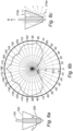
- FIG. 5a , 6a and 7a schematically shows a light distribution element 200 and a LED filament 120 of a LED filament arrangement 100 according to Fig. 3 and/or Fig. 4 .
- the light distribution elements 200 provide different light distribution intensity patterns. This is shown in the respective diagrams of Figs. 5b , 6b and 7b associated with the respective LED filament arrangements 100, schematically showing the light intensity as a function of the azimuth angle with respect to the axis B.
- the light distribution intensity pattern of Fig. 5b for the light distribution element 200 of ⁇ 1 shows a relatively large light intensity in a sideways direction of the light distribution element 200, such as in the range 60-140° from the central axis B of the light distribution element 200.
- FIG. 5b further shows a relatively small light intensity in a direction which is substantially parallel to the central axis B, such as in the range ⁇ 20° from the central axis B of the light distribution element 200.
- a relatively small light intensity in a direction which is substantially parallel to the central axis B, such as in the range ⁇ 20° from the central axis B of the light distribution element 200.
- the light distribution intensity is similar to that of Fig. 5b with respect to the downwards and sideways directions.
- the light distribution intensity in Fig. 6b is high in an upwards direction parallel to the central axis B.
- the light distribution intensity pattern shows a distinct peak in an upwards direction parallel to the central axis B, clearly indicating a spot light effect of the associated LED filament arrangement 100.
- FIG. 5c , 6c and 7c schematically shows the light rays emitted from a specific point of the LED filament 120 of the respective LED filament arrangement 100 of Figs. 5a , 6a , and 7a .
- the schematically indicated light rays of Figs. 5c , 6c , and 7c correspond to (or are associated with) the respective light distribution intensity patterns of Figs. 5b , 6b , and 7b . Accordingly, in Fig.
- the light rays of the bundle of light 210a which are emitted sideways from the conical-shaped light distribution element 200 due to refraction lead to a relatively high intensity in the range 60-140° from the central axis B of the light distribution element 200. Furthermore, the light rays of the bundle of light 210b which are emitted from the base 135 of the conical-shaped light distribution element 200 are not parallel to the central axis B, indicating a relatively small light intensity in this direction. It is also clear from Fig. 5c that almost no light is emitted downwards (according to the depicted orientation) from the LED filament arrangement 100.
- the light rays of the bundle of light 210a is similar to that of Fig. 5c with respect to the sideway direction of the light distribution element 200.
- the light rays of the bundle of light 210b in Fig. 6c are, to a larger extent, emitted in the upwards direction parallel to the central axis B.
- the light rays of the bundle of light 210b show a distinct peak in an upwards direction parallel to the central axis B, clearly indicating a spot light effect of the associated LED filament arrangement 100.
- Figs. 8a and 8b are schematic illustrations of LED filaments arrangement 100 according to embodiments of the present invention. It should be noted that some references have been omitted for reasons of an increased understanding, and it is referred to Fig. 3 and/or Fig. 4 for the configuration and/or properties of the light distribution element 200.
- the LED filament 120 has a length L and the light distribution element 200 has a height, H, wherein L/H may be 0.5-0.95, such as 0.6-0.92, such as 0.7-0.9.
- L/H may be 0.5-0.95, such as 0.6-0.92, such as 0.7-0.9.
- the length L of the LED filament 120 is smaller than the height H of the conical-shaped light distribution element 200.
- FIG. 8b which is another schematic illustration of a LED filament arrangement 100 according to an embodiment of the present invention, the opposite relationship to that of Fig. 8a is shown.
- the ratio L/H between the length L of the LED filament 120 and the height H of the light distribution element 200 is 1.1-2.5, such as 1.2-2.0, such as 1.2-1.8.
- the length L of the LED filament 120 is larger than the height H of the conical-shaped light distribution element 120.
- Figs. 9a-d are schematic illustrations of LED filament arrangements 100, each comprising two light distribution elements 200, according to exemplifying embodiments of the present invention.
- the respective LED filament arrangement 100 comprises a first light distribution element 200a and a second light distribution element 200b.
- the first and second light distribution elements 200a, 200b are adjacently arranged along a common axis, D, which coincides with the respective central axis of the first and second light distribution elements 200a, 200b.
- D common axis
- some references of the light distribution elements 200a, 200b have been omitted for reasons of an increased understanding, and it is referred to Fig. 3 and/or Fig. 4 .
- the first light distribution element 200a and the second light distribution element 200b are arranged such that the apexes of the first and second light distribution elements 200a, 200b face each other.
- the arrangement of the two identical and conical-shaped light distribution elements 200a, 200b of the LED filament arrangement 100 resembles that of a diabola.
- the first and second light distribution elements 200a, 200b are arranged in series such that the apex of the first light distribution element faces (is oriented towards) the base of the second light distribution element.
- the configuration or arrangement of the first and second light distribution elements 200a, 200b of the LED filament arrangement 100 may hereby resemble a Christmas tree.
- Fig. 9c shows an analogous arrangement to that of Fig. 9b , in that the first and second light distribution elements 200a, 200b are arranged in series such that the apex of the first light distribution element is oriented towards the base of the second light distribution element.
- the first light distribution element 200a and the second light distribution element 200b are arranged such that the bases of the first and second light distribution elements 200a, 200b face each other.
- Figs. 9a-9d show that the two light distribution elements 200a, 200b are in contact, there may alternatively be provided a space (not shown) between and/or below the two light distribution elements 200a, 200b.
- a spacer (not shown) may be provided between the two light distribution elements 200a, 200b and/or on top and/or below at least one of the two light distribution elements 200a, 200b.
- Fig. 10 schematically shows a lighting device 300.
- the lighting device 300 comprises a LED filament arrangement 100, which in turn comprises a light distribution element 200, according to any previously exemplified embodiment of the present invention.
- the lighting device 300 further comprises a cover 310, which is exemplified as being bulb-shaped and comprising a top portion 400 and a base portion 410.
- the cover 310 comprises an at least partially light transmissive (e.g. transparent) material and at least partially encloses the LED filament arrangement 100.
- the light distribution element 200 is enclosed by the cover 310.
- the light distribution element 200 is oriented in the cover 310 such that the apex 130 of the light distribution element 200 is directed towards the base portion 410 of the cover 310 of the lighting device 300, and the base 135 of the light distribution element 200 is directed towards the top portion 400 of the cover 310 of the lighting device 300.
- the light distribution element 200 may be oriented in the cover 310 such that the apex 130 of the light distribution element 200 is directed towards the top portion 400 of the cover 310 of the lighting device 300, and the base 135 of the light distribution element 200 is directed towards the base portion 410 of the cover 310 of the lighting device 300.
- the lighting device 300 further comprises an electrical connection 320 connected to the LED filament arrangement 100 for a supply of power to the plurality of LEDs of the LED filament arrangement 100.
- one or more of the LED filament(s) 120, the light distribution element(s) 200a, 200b, etc. may have different shapes, dimensions and/or sizes than those depicted/described.
Claims (15)
- Leuchtdioden-Filamentanordnung, LED-Filamentanordnung, (100), umfassendmindestens ein LED-Filament (120), umfassend ein Array mit einer Vielzahl von Leuchtdioden (140), LEDs, die zum Emittieren von Licht während des Betriebs angeordnet sind, undmindestens ein Lichtverteilungselement (200, 200a, 200b), das ein festes, zumindest teilweise lichtdurchlässiges Material und ein Loch (125) umfasst, das das mindestens eine LED-Filament zumindest teilweise umschließt, wobei das mindestens eine Lichtverteilungselement (200, 200a, 200b) eine konische Form aufweist, die eine Spitze (130) und eine Basis (135) aufweist, die durch die Seiten (145) verbunden sind, wobei das eine Lichtverteilungselement (200, 200a, 200b) konfiguriert ist, um das Licht zumindest teilweise zu brechen und das Licht über die Seiten (145) zu emittieren und das Licht zumindest teilweise durch Totalreflexion zu reflektieren und das Licht über die Basis (135) zu emittieren.
- LED-Filamentanordnung nach Anspruch 1, wobei sich das mindestens eine LED-Filament entlang einer Längsachse, A, erstreckt, und wobei eine Mittelachse, B, des Lichtverteilungselements parallel zu der Längsachse, A, ist.
- LED-Filamentanordnung nach Anspruch 1 oder 2, wobei das mindestens eine Lichtverteilungselement ferner mindestens ein Loch umfasst, und wobei jedes LED-Filament des mindestens einen LED-Filaments in einem jeweiligen Loch angeordnet ist.
- LED-Filamentanordnung nach einem der vorstehenden Ansprüche, wobei ein Spitzenwinkel α des mindestens einen Lichtverteilungselements α = 2θ ist, wobei θ 22-28°, wie etwa 23-26°, wie etwa 24°, beträgt.
- LED-Filamentanordnung nach einem der vorstehenden Ansprüche 1 bis 3, wobei ein Spitzenwinkel α des mindestens einen Lichtverteilungselements α = 2θ ist, wobei θ 30-40°, wie etwa 30-38°, wie etwa 30-35°, beträgt.
- LED-Filamentanordnung nach einem der vorstehenden Ansprüche, wobei das mindestens eine LED-Filament eine Länge, L, aufweist, und wobei das erste Lichtverteilungselement eine Höhe, H, aufweist, wobei L/H 0,5-0,95, wie etwa 0,6-0,92, wie etwa 0,7-0,9, beträgt.
- LED-Filamentanordnung nach einem der vorstehenden Ansprüche 1 bis 5, wobei das mindestens eine LED-Filament eine Länge, L, aufweist, und wobei das erste Lichtverteilungselement eine Höhe, H, aufweist, wobei L/H 1,1-2,5, wie etwa 1,2-2,0, wie etwa 1,2-1,8, beträgt.
- LED-Filamentanordnung nach einem der vorstehenden Ansprüche, wobei das mindestens eine Lichtverteilungselement ein Kollimator ist, der konfiguriert ist, um zumindest einen Teil des Lichts zu kollimieren, das während des Betriebs von dem mindestens einen LED-Filament emittiert wird.
- LED-Filamentanordnung nach einem der vorstehenden Ansprüche, umfassend ein erstes Lichtverteilungselement (200a) und ein zweites Lichtverteilungselement (200b), wobei das erste und das zweite Lichtverteilungselement entlang einer gemeinsamen Achse, D, benachbart angeordnet sind, die mit der jeweiligen Mittelachse des ersten und des zweiten Lichtverteilungselements zusammenfällt.
- LED-Filamentanordnung nach Anspruch 9, wobei das erste und das zweite Lichtverteilungselement eine identische Form aufweisen.
- LED-Filamentanordnung nach Anspruch 9 oder 10, wobei das erste und das zweite Lichtverteilungselement derart angeordnet sind, dass die Spitzen oder die Basen des ersten und des zweiten Lichtverteilungselements einander zugewandt sind.
- LED-Filamentanordnung nach Anspruch 9 oder 10, wobei das erste und das zweite Lichtverteilungselement in Reihe derart angeordnet sind, dass die Spitze des ersten Lichtverteilungselements der Basis des zweiten Lichtverteilungselements zugewandt ist.
- LED-Filamentanordnung nach einem der vorstehenden Ansprüche, wobei das mindestens eine LED-Filament konfiguriert ist, um Licht omnidirektional in der Ebene senkrecht zu der Längsachse, A, zu emittieren.
- Beleuchtungsvorrichtung (300), umfassendeine LED-Filamentanordnung nach einem der vorstehenden Ansprüche,eine Abdeckung (310), umfassend ein zumindest teilweise lichtdurchlässiges Material, wobei die Abdeckung die LED-Filamentanordnung zumindest teilweise umschließt, undeine elektrische Verbindung (320), die mit der LED-Filamentanordnung für eine Stromversorgung der Vielzahl von LEDs der LED-Filamentanordnung verbunden ist.
- Beleuchtungsvorrichtung (300), umfassendeine LED-Filamentanordnung nach einem der Ansprüche 1 bis 8,eine Abdeckung (310), umfassend ein zumindest teilweise lichtdurchlässiges Material, wobei die Abdeckung die LED-Filamentanordnung zumindest teilweise umschließt, undeine elektrische Verbindung (320), die mit der LED-Filamentanordnung für eine Stromversorgung der Vielzahl von LEDs der LED-Filamentanordnung verbunden ist,wobei die Abdeckung die Form einer Glühbirne aufweist und einen oberen Abschnitt (400) und einen Basisabschnitt (410) umfasst, wobei das Lichtverteilungselement zumindest teilweise von der Abdeckung umschlossen und ferner derart in der Abdeckung ausgerichtet ist, dass die Spitze des Lichtverteilungselements zu dem Basisabschnitt der Abdeckung gerichtet ist und die Basis des Lichtverteilungselements in Richtung des oberen Abschnitts der Abdeckung gerichtet ist.
Applications Claiming Priority (2)
| Application Number | Priority Date | Filing Date | Title |
|---|---|---|---|
| EP19153516 | 2019-01-24 | ||
| PCT/EP2020/051334 WO2020152124A1 (en) | 2019-01-24 | 2020-01-21 | Led filament arrangement |
Publications (2)
| Publication Number | Publication Date |
|---|---|
| EP3914852A1 EP3914852A1 (de) | 2021-12-01 |
| EP3914852B1 true EP3914852B1 (de) | 2023-08-23 |
Family
ID=65234415
Family Applications (1)
| Application Number | Title | Priority Date | Filing Date |
|---|---|---|---|
| EP20700733.7A Active EP3914852B1 (de) | 2019-01-24 | 2020-01-21 | Led-filament-anordnung |
Country Status (5)
| Country | Link |
|---|---|
| US (1) | US11421828B2 (de) |
| EP (1) | EP3914852B1 (de) |
| JP (1) | JP6997912B1 (de) |
| CN (1) | CN113366255A (de) |
| WO (1) | WO2020152124A1 (de) |
Citations (2)
| Publication number | Priority date | Publication date | Assignee | Title |
|---|---|---|---|---|
| DE102016105211A1 (de) * | 2016-03-21 | 2017-09-21 | Osram Opto Semiconductors Gmbh | Filament und dessen Herstellung sowie Leuchtmittel mit Filamenten |
| DE102017103431A1 (de) * | 2017-02-20 | 2018-08-23 | Osram Opto Semiconductors Gmbh | Strahlungsemittierendes Filament mit Wärmeleitungselement |
Family Cites Families (13)
| Publication number | Priority date | Publication date | Assignee | Title |
|---|---|---|---|---|
| SG11201405651VA (en) | 2012-03-12 | 2014-10-30 | Zhejiang Ledison Optoelectronics Co Ltd | Led light-emitting column and led light using the same |
| WO2014190304A1 (en) * | 2013-05-24 | 2014-11-27 | Anderson Deloren E | Led light bulb |
| CN203771136U (zh) | 2014-03-25 | 2014-08-13 | 杭州临安恒星照明电器有限公司 | 全角度反射u型led发光灯丝灯泡 |
| KR20150138886A (ko) * | 2014-05-30 | 2015-12-11 | (주)엔티시 | Led 조명장치 |
| CN104033774B (zh) | 2014-06-25 | 2016-08-17 | 连云港晶德照明电器有限公司 | 一种灯丝led灯泡 |
| CN204424304U (zh) * | 2014-10-15 | 2015-06-24 | 杨志强 | 立体led封装 |
| GB201503487D0 (en) | 2015-03-02 | 2015-04-15 | Buster & Punch Ltd | Light Bulb |
| CN105953101A (zh) | 2016-03-11 | 2016-09-21 | 浙江英特来光电科技有限公司 | 一种具有高散热性能的led球泡灯 |
| CA3011489A1 (en) | 2016-04-27 | 2017-11-02 | Jiaxing Super Lighting Electric Appliance Co., Ltd | Led light bulb |
| DK3507541T3 (da) | 2016-09-01 | 2020-04-06 | Signify Holding Bv | En lysemitterende indretning |
| CN206694870U (zh) | 2017-02-27 | 2017-12-01 | 深圳市崧森智能科技有限公司 | 一种高光效的led灯丝灯 |
| CN207049655U (zh) * | 2017-05-26 | 2018-02-27 | 浙江英特来光电科技有限公司 | 一种灯丝造型可变的灯丝灯 |
| CN208365255U (zh) * | 2018-07-13 | 2019-01-11 | 安徽芯瑞达科技股份有限公司 | 一种直下式灯条 |
-
2020
- 2020-01-21 EP EP20700733.7A patent/EP3914852B1/de active Active
- 2020-01-21 WO PCT/EP2020/051334 patent/WO2020152124A1/en unknown
- 2020-01-21 CN CN202080010787.3A patent/CN113366255A/zh active Pending
- 2020-01-21 JP JP2021540791A patent/JP6997912B1/ja active Active
- 2020-01-21 US US17/419,789 patent/US11421828B2/en active Active
Patent Citations (2)
| Publication number | Priority date | Publication date | Assignee | Title |
|---|---|---|---|---|
| DE102016105211A1 (de) * | 2016-03-21 | 2017-09-21 | Osram Opto Semiconductors Gmbh | Filament und dessen Herstellung sowie Leuchtmittel mit Filamenten |
| DE102017103431A1 (de) * | 2017-02-20 | 2018-08-23 | Osram Opto Semiconductors Gmbh | Strahlungsemittierendes Filament mit Wärmeleitungselement |
Also Published As
| Publication number | Publication date |
|---|---|
| CN113366255A (zh) | 2021-09-07 |
| US20220082213A1 (en) | 2022-03-17 |
| JP2022514109A (ja) | 2022-02-09 |
| WO2020152124A1 (en) | 2020-07-30 |
| US11421828B2 (en) | 2022-08-23 |
| EP3914852A1 (de) | 2021-12-01 |
| JP6997912B1 (ja) | 2022-01-18 |
Similar Documents
| Publication | Publication Date | Title |
|---|---|---|
| JP5711147B2 (ja) | Led、光ガイド及びリフレクタを備える光源 | |
| EP1259754B1 (de) | Leuchte mit reflektor und leuchtdioden | |
| US9690029B2 (en) | Optical waveguides and luminaires incorporating same | |
| US20180066808A1 (en) | Luminaires using waveguide bodies and optical elements | |
| KR101212911B1 (ko) | 조명모듈 및 조명기구 | |
| US10323824B1 (en) | LED light fixture with light shaping features | |
| US8602621B2 (en) | Optical element and light source comprising the same | |
| KR101981717B1 (ko) | 조명 장치 | |
| US20140211503A1 (en) | Waveguide bodies including redirection features and methods of producing same | |
| TWI414727B (zh) | 發光裝置 | |
| KR20120014325A (ko) | 광학 렌즈 및 조명 장치 | |
| EP3914852B1 (de) | Led-filament-anordnung | |
| EP3894738B1 (de) | Beleuchtungsvorrichtung mit lichtemittierenden fäden | |
| JP7461956B2 (ja) | Ledフィラメント構成 | |
| WO2020083658A1 (en) | A lighting device | |
| US11519562B2 (en) | LED filament arrangement | |
| JP7155458B1 (ja) | 照明デバイス | |
| WO2022248283A1 (en) | Led filament | |
| WO2022268500A1 (en) | Led filament arrangement | |
| KR101043597B1 (ko) | 도광캡 및 이를 포함하는 조명등 |
Legal Events
| Date | Code | Title | Description |
|---|---|---|---|
| STAA | Information on the status of an ep patent application or granted ep patent |
Free format text: STATUS: UNKNOWN |
|
| STAA | Information on the status of an ep patent application or granted ep patent |
Free format text: STATUS: THE INTERNATIONAL PUBLICATION HAS BEEN MADE |
|
| PUAI | Public reference made under article 153(3) epc to a published international application that has entered the european phase |
Free format text: ORIGINAL CODE: 0009012 |
|
| STAA | Information on the status of an ep patent application or granted ep patent |
Free format text: STATUS: REQUEST FOR EXAMINATION WAS MADE |
|
| 17P | Request for examination filed |
Effective date: 20210824 |
|
| AK | Designated contracting states |
Kind code of ref document: A1 Designated state(s): AL AT BE BG CH CY CZ DE DK EE ES FI FR GB GR HR HU IE IS IT LI LT LU LV MC MK MT NL NO PL PT RO RS SE SI SK SM TR |
|
| DAV | Request for validation of the european patent (deleted) | ||
| DAX | Request for extension of the european patent (deleted) | ||
| GRAP | Despatch of communication of intention to grant a patent |
Free format text: ORIGINAL CODE: EPIDOSNIGR1 |
|
| STAA | Information on the status of an ep patent application or granted ep patent |
Free format text: STATUS: GRANT OF PATENT IS INTENDED |
|
| INTG | Intention to grant announced |
Effective date: 20230321 |
|
| P01 | Opt-out of the competence of the unified patent court (upc) registered |
Effective date: 20230530 |
|
| GRAS | Grant fee paid |
Free format text: ORIGINAL CODE: EPIDOSNIGR3 |
|
| GRAA | (expected) grant |
Free format text: ORIGINAL CODE: 0009210 |
|
| STAA | Information on the status of an ep patent application or granted ep patent |
Free format text: STATUS: THE PATENT HAS BEEN GRANTED |
|
| AK | Designated contracting states |
Kind code of ref document: B1 Designated state(s): AL AT BE BG CH CY CZ DE DK EE ES FI FR GB GR HR HU IE IS IT LI LT LU LV MC MK MT NL NO PL PT RO RS SE SI SK SM TR |
|
| REG | Reference to a national code |
Ref country code: GB Ref legal event code: FG4D |
|
| REG | Reference to a national code |
Ref country code: CH Ref legal event code: EP |
|
| REG | Reference to a national code |
Ref country code: DE Ref legal event code: R096 Ref document number: 602020016217 Country of ref document: DE |
|
| REG | Reference to a national code |
Ref country code: IE Ref legal event code: FG4D |
|
| REG | Reference to a national code |
Ref country code: LT Ref legal event code: MG9D |
|
| REG | Reference to a national code |
Ref country code: NL Ref legal event code: MP Effective date: 20230823 |
|
| REG | Reference to a national code |
Ref country code: AT Ref legal event code: MK05 Ref document number: 1602963 Country of ref document: AT Kind code of ref document: T Effective date: 20230823 |
|
| PG25 | Lapsed in a contracting state [announced via postgrant information from national office to epo] |
Ref country code: GR Free format text: LAPSE BECAUSE OF FAILURE TO SUBMIT A TRANSLATION OF THE DESCRIPTION OR TO PAY THE FEE WITHIN THE PRESCRIBED TIME-LIMIT Effective date: 20231124 |
|
| PG25 | Lapsed in a contracting state [announced via postgrant information from national office to epo] |
Ref country code: IS Free format text: LAPSE BECAUSE OF FAILURE TO SUBMIT A TRANSLATION OF THE DESCRIPTION OR TO PAY THE FEE WITHIN THE PRESCRIBED TIME-LIMIT Effective date: 20231223 |
|
| PG25 | Lapsed in a contracting state [announced via postgrant information from national office to epo] |
Ref country code: SE Free format text: LAPSE BECAUSE OF FAILURE TO SUBMIT A TRANSLATION OF THE DESCRIPTION OR TO PAY THE FEE WITHIN THE PRESCRIBED TIME-LIMIT Effective date: 20230823 Ref country code: RS Free format text: LAPSE BECAUSE OF FAILURE TO SUBMIT A TRANSLATION OF THE DESCRIPTION OR TO PAY THE FEE WITHIN THE PRESCRIBED TIME-LIMIT Effective date: 20230823 Ref country code: PT Free format text: LAPSE BECAUSE OF FAILURE TO SUBMIT A TRANSLATION OF THE DESCRIPTION OR TO PAY THE FEE WITHIN THE PRESCRIBED TIME-LIMIT Effective date: 20231226 Ref country code: NO Free format text: LAPSE BECAUSE OF FAILURE TO SUBMIT A TRANSLATION OF THE DESCRIPTION OR TO PAY THE FEE WITHIN THE PRESCRIBED TIME-LIMIT Effective date: 20231123 Ref country code: NL Free format text: LAPSE BECAUSE OF FAILURE TO SUBMIT A TRANSLATION OF THE DESCRIPTION OR TO PAY THE FEE WITHIN THE PRESCRIBED TIME-LIMIT Effective date: 20230823 Ref country code: LV Free format text: LAPSE BECAUSE OF FAILURE TO SUBMIT A TRANSLATION OF THE DESCRIPTION OR TO PAY THE FEE WITHIN THE PRESCRIBED TIME-LIMIT Effective date: 20230823 Ref country code: LT Free format text: LAPSE BECAUSE OF FAILURE TO SUBMIT A TRANSLATION OF THE DESCRIPTION OR TO PAY THE FEE WITHIN THE PRESCRIBED TIME-LIMIT Effective date: 20230823 Ref country code: IS Free format text: LAPSE BECAUSE OF FAILURE TO SUBMIT A TRANSLATION OF THE DESCRIPTION OR TO PAY THE FEE WITHIN THE PRESCRIBED TIME-LIMIT Effective date: 20231223 Ref country code: HR Free format text: LAPSE BECAUSE OF FAILURE TO SUBMIT A TRANSLATION OF THE DESCRIPTION OR TO PAY THE FEE WITHIN THE PRESCRIBED TIME-LIMIT Effective date: 20230823 Ref country code: GR Free format text: LAPSE BECAUSE OF FAILURE TO SUBMIT A TRANSLATION OF THE DESCRIPTION OR TO PAY THE FEE WITHIN THE PRESCRIBED TIME-LIMIT Effective date: 20231124 Ref country code: FI Free format text: LAPSE BECAUSE OF FAILURE TO SUBMIT A TRANSLATION OF THE DESCRIPTION OR TO PAY THE FEE WITHIN THE PRESCRIBED TIME-LIMIT Effective date: 20230823 Ref country code: AT Free format text: LAPSE BECAUSE OF FAILURE TO SUBMIT A TRANSLATION OF THE DESCRIPTION OR TO PAY THE FEE WITHIN THE PRESCRIBED TIME-LIMIT Effective date: 20230823 |
|
| PG25 | Lapsed in a contracting state [announced via postgrant information from national office to epo] |
Ref country code: PL Free format text: LAPSE BECAUSE OF FAILURE TO SUBMIT A TRANSLATION OF THE DESCRIPTION OR TO PAY THE FEE WITHIN THE PRESCRIBED TIME-LIMIT Effective date: 20230823 |
|
| PG25 | Lapsed in a contracting state [announced via postgrant information from national office to epo] |
Ref country code: ES Free format text: LAPSE BECAUSE OF FAILURE TO SUBMIT A TRANSLATION OF THE DESCRIPTION OR TO PAY THE FEE WITHIN THE PRESCRIBED TIME-LIMIT Effective date: 20230823 |
|
| PG25 | Lapsed in a contracting state [announced via postgrant information from national office to epo] |
Ref country code: SM Free format text: LAPSE BECAUSE OF FAILURE TO SUBMIT A TRANSLATION OF THE DESCRIPTION OR TO PAY THE FEE WITHIN THE PRESCRIBED TIME-LIMIT Effective date: 20230823 Ref country code: RO Free format text: LAPSE BECAUSE OF FAILURE TO SUBMIT A TRANSLATION OF THE DESCRIPTION OR TO PAY THE FEE WITHIN THE PRESCRIBED TIME-LIMIT Effective date: 20230823 Ref country code: ES Free format text: LAPSE BECAUSE OF FAILURE TO SUBMIT A TRANSLATION OF THE DESCRIPTION OR TO PAY THE FEE WITHIN THE PRESCRIBED TIME-LIMIT Effective date: 20230823 Ref country code: EE Free format text: LAPSE BECAUSE OF FAILURE TO SUBMIT A TRANSLATION OF THE DESCRIPTION OR TO PAY THE FEE WITHIN THE PRESCRIBED TIME-LIMIT Effective date: 20230823 Ref country code: DK Free format text: LAPSE BECAUSE OF FAILURE TO SUBMIT A TRANSLATION OF THE DESCRIPTION OR TO PAY THE FEE WITHIN THE PRESCRIBED TIME-LIMIT Effective date: 20230823 Ref country code: CZ Free format text: LAPSE BECAUSE OF FAILURE TO SUBMIT A TRANSLATION OF THE DESCRIPTION OR TO PAY THE FEE WITHIN THE PRESCRIBED TIME-LIMIT Effective date: 20230823 Ref country code: SK Free format text: LAPSE BECAUSE OF FAILURE TO SUBMIT A TRANSLATION OF THE DESCRIPTION OR TO PAY THE FEE WITHIN THE PRESCRIBED TIME-LIMIT Effective date: 20230823 |
|
| PGFP | Annual fee paid to national office [announced via postgrant information from national office to epo] |
Ref country code: DE Payment date: 20240328 Year of fee payment: 5 Ref country code: GB Payment date: 20240123 Year of fee payment: 5 |