EP3913228A1 - Non-positive displacement type pump and liquid supply device - Google Patents
Non-positive displacement type pump and liquid supply device Download PDFInfo
- Publication number
- EP3913228A1 EP3913228A1 EP20741647.0A EP20741647A EP3913228A1 EP 3913228 A1 EP3913228 A1 EP 3913228A1 EP 20741647 A EP20741647 A EP 20741647A EP 3913228 A1 EP3913228 A1 EP 3913228A1
- Authority
- EP
- European Patent Office
- Prior art keywords
- impeller
- pump
- case
- suction port
- discharge port
- Prior art date
- Legal status (The legal status is an assumption and is not a legal conclusion. Google has not performed a legal analysis and makes no representation as to the accuracy of the status listed.)
- Withdrawn
Links
- 239000007788 liquid Substances 0.000 title claims abstract description 29
- 238000006073 displacement reaction Methods 0.000 title claims abstract description 25
- 230000002093 peripheral effect Effects 0.000 claims description 78
- 239000000446 fuel Substances 0.000 description 57
- 239000011347 resin Substances 0.000 description 11
- 229920005989 resin Polymers 0.000 description 11
- 238000009835 boiling Methods 0.000 description 6
- 238000003780 insertion Methods 0.000 description 6
- 230000037431 insertion Effects 0.000 description 6
- 238000004804 winding Methods 0.000 description 5
- 230000000694 effects Effects 0.000 description 3
- 238000007599 discharging Methods 0.000 description 2
- 239000002828 fuel tank Substances 0.000 description 2
- 239000000463 material Substances 0.000 description 2
- 229920001973 fluoroelastomer Polymers 0.000 description 1
- 230000004907 flux Effects 0.000 description 1
- 230000005484 gravity Effects 0.000 description 1
- 239000002184 metal Substances 0.000 description 1
- 238000012986 modification Methods 0.000 description 1
- 230000004048 modification Effects 0.000 description 1
- 238000000465 moulding Methods 0.000 description 1
- 238000007789 sealing Methods 0.000 description 1
Images



Classifications
-
- F—MECHANICAL ENGINEERING; LIGHTING; HEATING; WEAPONS; BLASTING
- F04—POSITIVE - DISPLACEMENT MACHINES FOR LIQUIDS; PUMPS FOR LIQUIDS OR ELASTIC FLUIDS
- F04D—NON-POSITIVE-DISPLACEMENT PUMPS
- F04D5/00—Pumps with circumferential or transverse flow
- F04D5/002—Regenerative pumps
-
- F—MECHANICAL ENGINEERING; LIGHTING; HEATING; WEAPONS; BLASTING
- F02—COMBUSTION ENGINES; HOT-GAS OR COMBUSTION-PRODUCT ENGINE PLANTS
- F02M—SUPPLYING COMBUSTION ENGINES IN GENERAL WITH COMBUSTIBLE MIXTURES OR CONSTITUENTS THEREOF
- F02M37/00—Apparatus or systems for feeding liquid fuel from storage containers to carburettors or fuel-injection apparatus; Arrangements for purifying liquid fuel specially adapted for, or arranged on, internal-combustion engines
- F02M37/04—Feeding by means of driven pumps
- F02M37/08—Feeding by means of driven pumps electrically driven
-
- F—MECHANICAL ENGINEERING; LIGHTING; HEATING; WEAPONS; BLASTING
- F02—COMBUSTION ENGINES; HOT-GAS OR COMBUSTION-PRODUCT ENGINE PLANTS
- F02M—SUPPLYING COMBUSTION ENGINES IN GENERAL WITH COMBUSTIBLE MIXTURES OR CONSTITUENTS THEREOF
- F02M37/00—Apparatus or systems for feeding liquid fuel from storage containers to carburettors or fuel-injection apparatus; Arrangements for purifying liquid fuel specially adapted for, or arranged on, internal-combustion engines
- F02M37/04—Feeding by means of driven pumps
- F02M37/08—Feeding by means of driven pumps electrically driven
- F02M37/10—Feeding by means of driven pumps electrically driven submerged in fuel, e.g. in reservoir
-
- F—MECHANICAL ENGINEERING; LIGHTING; HEATING; WEAPONS; BLASTING
- F04—POSITIVE - DISPLACEMENT MACHINES FOR LIQUIDS; PUMPS FOR LIQUIDS OR ELASTIC FLUIDS
- F04D—NON-POSITIVE-DISPLACEMENT PUMPS
- F04D29/00—Details, component parts, or accessories
- F04D29/08—Sealings
- F04D29/16—Sealings between pressure and suction sides
- F04D29/165—Sealings between pressure and suction sides especially adapted for liquid pumps
-
- F—MECHANICAL ENGINEERING; LIGHTING; HEATING; WEAPONS; BLASTING
- F04—POSITIVE - DISPLACEMENT MACHINES FOR LIQUIDS; PUMPS FOR LIQUIDS OR ELASTIC FLUIDS
- F04D—NON-POSITIVE-DISPLACEMENT PUMPS
- F04D29/00—Details, component parts, or accessories
- F04D29/18—Rotors
- F04D29/188—Rotors specially for regenerative pumps
-
- F—MECHANICAL ENGINEERING; LIGHTING; HEATING; WEAPONS; BLASTING
- F04—POSITIVE - DISPLACEMENT MACHINES FOR LIQUIDS; PUMPS FOR LIQUIDS OR ELASTIC FLUIDS
- F04D—NON-POSITIVE-DISPLACEMENT PUMPS
- F04D29/00—Details, component parts, or accessories
- F04D29/66—Combating cavitation, whirls, noise, vibration or the like; Balancing
- F04D29/669—Combating cavitation, whirls, noise, vibration or the like; Balancing especially adapted for liquid pumps
-
- F—MECHANICAL ENGINEERING; LIGHTING; HEATING; WEAPONS; BLASTING
- F04—POSITIVE - DISPLACEMENT MACHINES FOR LIQUIDS; PUMPS FOR LIQUIDS OR ELASTIC FLUIDS
- F04D—NON-POSITIVE-DISPLACEMENT PUMPS
- F04D5/00—Pumps with circumferential or transverse flow
- F04D5/002—Regenerative pumps
- F04D5/008—Details of the stator, e.g. channel shape
Definitions
- the present invention relates to a non-positive displacement type pump and a liquid supply device.
- a non-positive displacement type pump includes an impeller having a substantial disc shape and a pump case formed in a manner of covering the entire impeller.
- the impeller is formed with a plurality of blade portions that are arranged in a peripheral direction.
- a plurality of through flow paths that pass through the impeller in a plate thickness direction of the impeller are formed among the blade portions.
- the pump case rotatably accommodates the impeller.
- the pump case includes a suction port and a discharge port disposed at two sides of the impeller.
- Such a non-positive displacement type pump is used as a liquid supply device (fuel pump) for a vehicle such as a motorcycle or a four-wheeled vehicle.
- This type of liquid supply device is disposed in a fuel tank.
- a portion from the discharge port to the suction port in a rotation direction of the impeller serves as a seal portion so that the discharge port and the suction port do not communicate with each other.
- the seal portion is provided to suppress the fuel in the discharge port from leaking to the suction port side.
- a flow rate characteristic of the non-positive displacement type pump is determined by a length of the seal portion in the peripheral direction. That is, when the length of the seal portion in the peripheral direction is short, the amount of the fuel drawn into the through flow paths of the impeller is increased by this amount, and thus a discharge flow rate of the non-positive displacement type pump is increased. On the other hand, when the length of the seal portion in the peripheral direction is long, the amount of the fuel drawn into the through flow paths of the impeller is reduced by this amount, so that a discharge flow rate of the non-positive displacement type pump is reduced.
- an object of the present invention is to provide a non-positive displacement type pump and a liquid supply device that can reduce noise at the time of driving while ensuring an appropriate discharge flow rate.
- a non-positive displacement type pump includes:
- a liquid supply device includes:
- the present invention it is possible to ensure an appropriate discharge flow rate of the non-positive displacement type pump.
- a distance of the seal portion in the peripheral direction can be made appropriate, and depressurization boiling of liquid sent from the discharge port to the suction port can be suppressed. Therefore, noise generated at the time of driving the non-positive displacement type pump can be reduced.
- FIG. 1 is a perspective view of a liquid supply device 1.
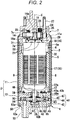
- FIG. 2 is a cross-sectional view taken along an axial direction of the liquid supply device 1.
- the liquid supply device 1 is used as a fuel pump for a vehicle such as a motorcycle and a four-wheeled vehicle.
- the liquid supply device 1 is a so-called in-tank type fuel pump disposed in a fuel tank (not shown).
- the liquid supply device 1 includes a substantially cylindrical metal housing 2, a motor portion 3, and a pump portion 4.
- the motor portion 3 and the pump portion 4 are fitted to an inner peripheral surface of the housing 2 and are arranged side by side in an axial direction of the housing 2.
- the housing 2, the motor portion 3, and the pump portion 4 are coaxially arranged.
- the liquid supply device 1 is used with the pump portion 4 facing downward in the direction of gravity. Therefore, a motor portion 3 side may be referred to as an upper side and a pump portion 4 side may be referred to as a lower side in the following description.
- an axial direction of the housing 2, the motor portion 3, and the pump portion 4 is simply referred to as an axial direction
- a radial direction of the housing 2 is simply referred to as a radial direction
- a peripheral direction of the housing 2, the motor portion 3, and the pump portion 4 is simply referred to as a peripheral direction.
- the housing 2 is formed by integrally molding a motor fitting portion 11 to which the motor portion 3 is fitted and a pump fitting portion 12 which is formed to have a smaller diameter than the motor fitting portion 11 via a step and to which the pump portion 4 is fitted.
- a positioning protrusion portion 13 that protrudes inward in the radial direction is formed on an inner peripheral surface of the pump fitting portion 12.
- the positioning protrusion portion 13 is formed by pressing the housing 2 from an outer side in the radial direction by press working or the like.
- the positioning protrusion portion 13 positions the housing 2 and the pump portion 4 in the peripheral direction.
- the positioning protrusion portion 13 is formed into a rectangular shape that is long in the axial direction when viewed from the radial direction.
- An inner flange portion 12a that extends inward in the radial direction is bent and extended from a lower end of the pump fitting portion 12 in the housing 2.
- the positioning protrusion portion 13 and the inner flange portion 12a position the housing 2 and the pump portion 4 in the axial direction.
- a brush-equipped motor is adopted as the motor portion 3.
- the motor portion 3 mainly includes a substantially cylindrical yoke 5, a permanent magnet 8 provided on an inner peripheral surface of the yoke 5, an armature 6 rotatably provided in the yoke 5, an outlet cover 7 that closes an upper opening 5a of the yoke 5, and a brush 25 accommodated in the outlet cover 7.
- An outer peripheral surface of the yoke 5 is fitted to an inner peripheral surface of the housing 2.
- the yoke 5 serves as a magnetic path through which a magnetic flux of the permanent magnet 8 passes.
- the upper opening 5a of the yoke 5 is fitted to an outer peripheral surface of a spigot joint portion 31 of the outlet cover 7 to be described later.
- Positioning of the outlet cover 7 and the yoke 5 in the peripheral direction is performed by recess/projection fitting of a positioning protrusion portion (not shown) formed on the outlet cover 7 and a yoke positioning recessed portion (not shown) formed on the yoke 5.
- Two permanent magnets 8 are provided on an inner peripheral surface of the yoke 5. Each of the permanent magnets 8 is formed into a substantially semicircular shape along the inner peripheral surface of the yoke 5 when viewed from the axial direction. A length in the axial direction of the permanent magnet 8 is set to be longer than a length in the axial direction of an armature core 15. The permanent magnet 8 is disposed such that two ends in the axial direction of the permanent magnet 8 protrude (overhang) from two ends in the axial direction of the armature core 15. A magnetic field orientation of the permanent magnet 8 is along the radial direction (a thickness direction of the permanent magnet 8).
- the permanent magnets 8 are arranged to face each other in the radial direction around a rotation shaft 14. Minute gaps are formed between an inner peripheral surface of the permanent magnet 8 and an outer end in the radial direction of teeth 17 of the armature core 15 and between an inner peripheral surface of the permanent magnet 8 and an outer end in the radial direction of a resin mold portion 22.
- the teeth 17 and the resin mold portion 22 will be described later.
- the armature 6 mainly includes the rotation shaft 14, the armature core 15 fitted and fixed to an outer peripheral surface of the rotation shaft 14, and a commutator 16 fitted and fixed to the outer peripheral surface of the rotation shaft 14 at a position closer to the outlet cover 7 than the armature core 15.
- the armature core 15 has a plurality of teeth 17 extending radially outward in the radial direction.
- a winding (not shown) is wound around the teeth 17.
- a terminal portion of the winding (not shown) is connected to the commutator 16.
- the commutator 16 is a so-called disc type commutator having a commutator body 18 formed of resin and formed into a substantial disc shape.
- a plurality of segments 19 are arranged side by side in the peripheral direction on a surface 18a of the commutator body 18 opposite to the armature core 15.
- Risers 21 that are bent and extended toward the armature core 15 over an outer peripheral surface of the commutator body 18 are integrally formed with an outer end in the radial direction of the segment 19.
- One end of the winding (not shown) is connected to each riser 21.
- the resin mold portion 22 is formed into a substantially columnar shape.
- the resin mold portion 22 extends from a position closer to the pump portion 4 than the armature core 15 to a substantially center portion of the commutator body 18 in the axial direction. Only outer ends in the radial direction (outer peripheral surfaces) of the teeth 17 of the armature core 15 are exposed, and the winding (not shown) is buried in the resin mold portion 22.
- a round chamfered portion 22a is formed at a corner portion of an end of the resin mold portion 22 that is close to the pump portion 4. Accordingly, the end of the resin mold portion 22 that is close to the pump portion 4 is tapered.
- the outlet cover 7 is formed into a substantially bottomed cylindrical shape having an opening portion 7a at the armature core 15 side.
- a bearing cylindrical portion 23 protruding toward the armature core 15 is integrally formed with a bottom portion 7b of the outlet cover 7 at a substantially center portion in the radial direction.
- An upper end portion 14a of the rotation shaft 14 is rotatably supported by the bearing cylindrical portion 23.
- Brush holders 24 are integrally formed at two sides of the bearing cylindrical portion 23 at the bottom portion 7b of the outlet cover 7. Each of the brush holders 24 is formed into a box shape having an opening at the commutator 16 side.
- the brush 25 is accommodated in the brush holder 24 in a slidable manner along the axial direction.
- a coil spring 26 is accommodated in the brush holder 24 in a compressed and deformed state.
- the brush 25 is biased toward the commutator 16 by the coil spring 26.
- a tip end of the brush 25 protrudes from the brush holder 24 and is in sliding contact with the segment 19.
- a terminal 27 that passes through the bottom portion 7b in an upper-lower direction is provided in the bottom portion 7b of the outlet cover 7.
- the brush 25 is connected to the terminal 27 via a pigtail (not shown).
- An external power supply (not shown) is connected to the terminal 27. Accordingly, external power is supplied to the winding (not shown) via the terminal 27, the pigtail (not shown), the brush 25, and the segment 19.
- a discharge port 28 protruding upward is integrally formed with the bottom portion 7b of the outlet cover 7.
- the discharge port 28 is a portion from which fuel pumped up by the liquid supply device 1 is discharged, and is connected to a fuel flow path (not shown).
- An inner side and an outer side of the outlet cover 7 communicate with each other via the discharge port 28.
- a positioning piece 32 extending downward is integrally formed with a peripheral wall 7c of the outlet cover 7.
- the positioning piece 32 is interposed between the permanent magnets 8 and positions the permanent magnets 8 (yoke 5) and the outlet cover 7.
- the peripheral wall 7c of the outlet cover 7 is formed with a fitting ridge portion 29 extending outward in the radial direction over the entire outer peripheral surface.
- An outer diameter of the fitting ridge portion 29 is set to be substantially the same as an inner diameter of the motor fitting portion 11 of the housing 2.
- An outer peripheral surface of the fitting ridge portion 29 is fitted to an inner peripheral surface of the motor fitting portion 11.
- An upper opening edge portion 11a of the motor fitting portion 11 is crimped inward in the radial direction from above the fitting ridge portion 29 of the outlet cover 7.
- a lower side of the fitting ridge portion 29 on the peripheral wall 7c of the outlet cover 7 serves as the spigot joint portion 31 to be spigot fitted to the yoke 5.
- a lower end portion of the rotation shaft 14 is inserted into the pump portion 4.
- a non-positive displacement type pump having an impeller 40 is used as the pump portion 4.
- the pump portion 4 includes the impeller 40 and a pump case 41 formed in a manner of covering the entire impeller 40.
- the pump case 41 is fitted to the pump fitting portion 12 of the housing 2.
- FIG. 3 is a perspective view of the impeller 40.
- the impeller 40 is formed of a resin material and is formed into a substantial disc shape.
- An insertion hole 61 through which the lower end portion 14b of the rotation shaft 14 can be inserted is formed at a substantially center portion in the radial direction of the impeller 40.
- the lower end portion 14b of the rotation shaft 14 is formed to have a substantially D-shaped cross section orthogonal to the axial direction.
- the insertion hole 61 of the impeller 40 is formed into a substantially D shape when viewed in the axial direction so as to correspond to the cross-sectional shape of the lower end portion 14b of the rotation shaft 14.
- a plurality of blade portions 62 (also see FIG. 6 ) having a substantially L-shaped cross section along the axial direction are formed near an outer peripheral portion of the impeller 40.
- the blade portions 62 are arranged at equal intervals in the peripheral direction so that peripheral directions of the blade portions 62 are the same.
- a through flow path 63 is formed between blade portions 62 adjacent to each other in the peripheral direction. The through flow path 63 passes through the impeller 40 in a plate thickness direction.
- the pump case 41 that covers the entire impeller 40 includes an upper case 43, a middle case 44, and a lower case 42.
- FIG. 4 is a plan view of the upper case 43 when viewed from the lower case 42 side (lower side).
- the upper case 43 is disposed on the impeller 40 at a side close to the motor portion 3.
- the upper case 43 is formed into a substantial disc shape in a manner of covering an upper surface of the impeller 40.
- the middle case 44 is joined to an outer peripheral portion of the upper case 43.
- An outer diameter of the upper case 43 is set to be slightly smaller than an outer diameter of the yoke 5.
- An insertion hole 46 through which the lower end portion 14b of the rotation shaft 14 can be inserted is formed at a center portion in the radial direction of the upper case 43.
- the rotation shaft 14 is rotatably supported in the insertion hole 46 via a slide bearing 59.
- a recessed portion 47 having a substantially annular shape when viewed in the axial direction is formed in an upper surface 43a of the upper case 43 in a manner of surrounding a periphery of the insertion hole 46.
- an outer peripheral side of the recessed portion 47 serves as a contact surface 43b that is brought into contact with the yoke 5. Since a sufficient space is ensured for the contact surface 43b, even when a lower end of the yoke 5 is brought into contact with the contact surface 43b, buckling deformation of the contact surface 43b or the yoke 5 is suppressed.
- a discharge port 48 that passes through the upper case 43 in the upper-lower direction is formed in the upper surface 43a of the upper case 43 near an outer peripheral portion of the recessed portion 47.
- a recessed portion 48a that expands an opening of the discharge port 48 is formed at a peripheral edge of the discharge port 48.
- the recessed portion 48a is formed in a manner of expanding toward the lower surface 43c of the upper case 43.
- the lower surface 43c of the upper case 43 serves as a first sliding contact surface 43d that is in sliding contact with the impeller 40.
- a first flow path groove 64 having a substantial arc shape (a substantial C shape) when viewed from the axial direction is formed on the first sliding contact surface 43d at a position facing the through flow path 63 of the impeller 40 in the axial direction.
- One end in the peripheral direction of the first flow path groove 64 communicates with the discharge port 48 (the recessed portion 48a).
- a tapered portion 64a is formed at the other end in the peripheral direction of the first flow path groove 64 in a manner of being tapered when viewed in the axial direction.
- the middle case 44 is formed into a substantial ring shape in a manner of surrounding an outer peripheral surface of the impeller 40.
- the middle case 44 is formed integrally with the upper case 43.
- An outer diameter of the middle case 44 is set to be slightly larger than the outer diameter of the upper case 43.
- the middle case 44 aligns a center in the radial direction of the impeller 40 with an axial center C of the rotation shaft 14.
- a thickness of the middle case 44 in the axial direction is substantially the same as or slightly larger than a plate thickness of the impeller 40. Accordingly, predetermined clearances are respectively formed between the impeller 40 and the upper case 43 and between the impeller 40 and the lower case 42.
- FIG. 5 is a plan view of the lower case 42 when viewed from the upper case 43 side (from above).
- FIG. 5 shows the lower case 42 in a manner in which a position in the peripheral direction of a first seal portion 66 provided in the upper case 43 shown in FIG. 4 substantially coincides with a position in the peripheral direction of a second seal portion 67 provided in the lower case 42 shown in FIG. 5 .
- the lower case 42 is disposed below the impeller 40.
- the pump case 41 includes the upper case 43 integrally formed with the middle case 44 and the lower case 42, and covers the entire impeller 40.
- the lower surface 43c of the upper case 43 and the upper surface 42a of the lower case 42 form an accommodating portion 60 that accommodates the impeller 40.
- the lower case 42 is formed into a substantial disc shape.
- An outer diameter of the lower case 42 is set to be substantially the same as an outer diameter of the middle case 44.
- a substantially cylindrical suction port 53 protruding downward is formed at an outer peripheral side of the lower surface 42b of the lower case 42.
- a tapered hole portion 53a is formed in an inner peripheral surface of the suction port 53 at the upper surface 42a side of the lower case 42 in a manner in which an opening area gradually increases toward the upper surface 42a.
- a step portion 49 is formed on an outer peripheral edge of the lower surface 42b of the lower case 42.
- the step portion 49 is formed by reducing a diameter of the lower surface 42b of the lower case 42.
- the step portion 49 is formed at a position overlapping with the inner flange portion 12a of the housing 2 when viewed in the axial direction.
- the upper surface 42a of the lower case 42 serves as a second sliding contact surface 42c that is in sliding contact with the impeller 40.
- a bearing accommodating recessed portion 54 that faces the lower end portion 14b of the rotation shaft 14 is formed in the upper surface 42a of the lower case 42 at a substantially center portion in the radial direction.
- a thrust bearing 55 is accommodated in the bearing accommodating recessed portion 54.
- the lower end portion 14b of the rotation shaft 14 is rotatably supported by the lower case 42 in a state where the lower end portion 14b is brought into contact with the thrust bearing 55.
- the thrust bearing 55 receives a thrust load of the rotation shaft 14.
- a second flow path groove 65 having a substantial arc shape (substantial C shape) when viewed in the axial direction is formed on the second sliding contact surface 42c of the lower case 42 at a position facing the through flow path 63 of the impeller 40 in the axial direction and facing the first flow path groove 64 of the upper case 43.
- One end in the peripheral direction of the second flow path groove 65 communicates with the suction port 53 (tapered hole portion 53a).
- a tapered portion 65a is formed at the other end in the peripheral direction of the second flow path groove 65 in a manner of being tapered when viewed in the axial direction.
- a vent hole 68 is formed in a manner of passing through the lower case 42 in a plate thickness direction of the lower case 42 at a position slightly closer to the suction port 53 than a center between the suction port 53 and the tapered portion 65a.
- the vent hole 68 is a hole for discharging vapor (air bubbles) generated in the pump case 41.
- the discharge port 48 that communicates with one end in the peripheral direction of the first flow path groove 64 and the tapered portion 64a formed at the other end in the peripheral direction of the first flow path groove 64, and the suction port 53 that communicates with one end in the peripheral direction of the second flow path groove 65 and the tapered portion 65a formed at the other end in the peripheral direction of the second flow path groove 65, are alternately arranged. That is, the discharge port 48 faces the tapered portion 65a of the second flow path groove 65 in the axial direction.
- the suction port 53 faces the tapered portion 64a of the first flow path groove 64 in the axial direction.
- a portion of the first sliding contact surface 43d of the upper case 43 between the discharge port 48 (the recessed portion 48a) and the tapered portion 64a of the first flow path groove 64 serves as the first seal portion 66 for suppressing leakage of fuel from the discharge port 48 to the tapered portion 64a.
- a portion of the second sliding contact surface 42c of the lower case 42 between the suction port 53 (tapered hole portion 53a) and the tapered portion 65a of the second flow path groove 65 serves as the second seal portion 67 for suppressing leakage of fuel from the tapered portion 65a to the suction port 53.
- a range (length) in the peripheral direction of the first seal portion 66 and a range (length) in the peripheral direction of the second seal portion 67 coincide with each other.
- first seal portion 66 and the second seal portion 67 will be described in detail later. As can be seen from FIG. 6 , the first seal portion 66 and the second seal portion 67 are positioned between the discharge port 48 and the suction port 53 and are positioned on a rotation trajectory of the through flow path 63.
- a square ring 50 serving as a seal member is mounted to the step portion 49 formed on the lower surface 42b of the lower case 42.
- the square ring 50 is a member that has a substantially rectangular cross section and is formed of a material having excellent oil resistance such as fluoro rubber.
- An outer diameter of the square ring 50 is set to be slightly smaller than an outer diameter of the lower case 42. Therefore, outer peripheral surfaces of the upper case 43, the middle case 44, and the lower case 42 are fitted to the pump fitting portion 12 of the housing 2.
- a minute gap is formed between an outer peripheral surface of the square ring 50 and an inner peripheral surface of the pump fitting portion 12 of the housing 2.
- the square ring 50 is brought into contact with the inner flange portion 12a of the housing 2.
- the positioning protrusion portion 13 of the housing 2 is inserted into a recessed portion (not shown) formed on an outer peripheral surface of the pump case 41. Accordingly, the housing 2 and the pump portion 4 are positioned in the peripheral direction.
- the upper opening edge portion 11a of the motor fitting portion 11 is crimped inward in the radial direction from above the fitting ridge portion 29 of the outlet cover 7 while the square ring 50 is slightly crushed by the step portion 49 of the lower case 42 and the inner flange portion 12a. Accordingly, the pump portion 4 is fitted to the pump fitting portion 12 of the housing 2.
- the motor portion 3 is fitted to the motor fitting portion 11 of the housing 2. Then, the motor portion 3 and the pump portion 4 are positioned relative to the housing 2, and the housing 2, the motor portion 3, and the pump portion 4 are integrated. Further, a sealing property between the housing 2 and the pump portion 4 is ensured by the square ring 50.
- FIG. 6 is a simplified view of a cross section taken along the axial direction of the pump portion 4.
- the pressurized fuel N is discharged into the yoke 5 of the motor portion 3 through the discharge port 48. That is, a pressure of the fuel N in the discharge port 48 is higher than a pressure of the fuel N in the suction port 53.
- the first seal portion 66 and the second seal portion 67 are provided between the discharge port 48 and the suction port 53. Therefore, the fuel N discharged from the discharge port 48 is suppressed from leaking to the suction port 53, the first flow path groove 64, and a portion of the second flow path groove 65 that intersects with the suction port 53 in the axial direction.
- the fuel N discharged into the yoke 5 is pressure-fed to the discharge port 28 through a minute gap between the permanent magnet 8 and the resin mold portion 22 (an outer end in the radial direction of the teeth 17 of the armature core 15). Thereafter, the fuel is pressure-fed to an engine or the like (not shown) through the discharge port 28.
- the range (length) in the peripheral direction of the first seal portion 66 and the range (length) in the peripheral direction of the second seal portion 67 are set as follows.
- straight lines respectively connecting two ends in the peripheral direction of the first seal portion 66 with the axial center C of the rotation shaft 14 are defined as L1.
- the two ends in the peripheral direction of the first seal portion 66 are a position where the straight line L1 that passes through the axial center C is in contact with the tapered portion 64a of the first flow path groove 64 and a position where the straight line L1 is in contact with the recessed portion 48a of the discharge port 48.
- straight lines respectively connecting two ends in the peripheral direction of the second seal portion 67 with the axial center C of the rotation shaft 14 are defined as L2.
- the two ends in the peripheral direction of the second seal portion 67 are a position where the straight line L2 that passes through the axial center C is in contact with the tapered portion 65a of the second flow path groove 65 and a position where the straight line L2 is in contact with the tapered hole portion 53a of the suction port 53.
- a portion of the first sliding contact surface 43d of the upper case 43 that is located between the two straight lines L1 and faces the blade portions 62 and the through flow path 63 of the impeller 40 in the axial direction serves as the first seal portion 66.
- a portion of the second sliding contact surface 42c of the lower case 42 that is located between the two straight lines L2 and faces the blade portions 62 and the through flow path 63 of the impeller 40 in the axial direction serves the second seal portion 67.
- angles ⁇ 1 and ⁇ 2 are set so as to satisfy 43° ⁇ ⁇ 1 ⁇ 47° and 43° ⁇ ⁇ 2 ⁇ 47°.
- the first seal portion 66 and the second seal portion 67 are formed to have a size at which the first seal portion 66 and the second seal portion 67 can close at least two through flow paths 63 between two ends in the peripheral direction of each of the first seal portion 66 and the second seal portion 67.
- a condition of the seal portions 66 and 67 having a size at which the seal portions 66 and 67 can close the at least two through flow paths 63 and satisfying the above formula (1) is hereinafter referred to as a seal condition.
- FIG. 7 is a graph showing a comparison between a fuel discharge flow rate in a case where the seal portions 66 and 67 satisfy the seal condition and a fuel discharge flow rate in a case where the seal portions 66 and 67 do not satisfy the seal condition, in which a vertical axis indicates a fuel discharge flow rate [L/h] of the pump portion 4 (hereinafter, simply referred to as a fuel discharge flow rate).
- FIG. 8 is a graph showing changes of a fuel discharge flow rate and a fuel sound pressure level, in which a vertical axis indicates a fuel discharge flow rate [L/h] and a fuel sound pressure level [dB] in the vicinity of the suction port 53 when the fuel having a high pressure is fed to the suction port 53, and in which a horizontal axis indicates the angle ⁇ 1 [°] between the two straight lines L1 and the angle ⁇ 2 [°] between the two straight lines L2 of the seal portions 66 and 67.
- the fuel sound pressure level can be reduced while satisfying a range W of a desired discharge flow rate in a range in which the angle ⁇ 1 between the two straight lines L1 and the angle ⁇ 2 between the two straight lines L2 of the seal portions 66 and 67 satisfy the above formula (1).
- the range W of the discharge flow rate is determined as a range in which both an allowable sound pressure level and a practically desirable discharge flow rate can be achieved when the liquid supply device 1 of the present type is used in practice.
- the seal portions 66 and 67 satisfy the seal condition, the sound pressure level can be reduced as compared with that in the related art, and the condition of the flow rate can be satisfied as compared with "67°". Therefore, when the seal portions 66 and 67 satisfy the seal condition, it can be confirmed that a performance balance between the flow rate and the sound pressure level is good.
- the pump portion 4 when the seal portions 66 and 67 satisfy the seal condition, the pump portion 4 can ensure an appropriate fuel discharge flow rate. Further, when the angles ⁇ 1 between the two straight lines L1 and the angle ⁇ 2 between the two straight lines L2 of the seal portions 66 and 67 satisfy the above formula (1), the ranges (lengths) in the peripheral direction of the seal portions 66 and 67 can be made appropriate. As a result, depressurization boiling of the fuel fed from the discharge port 48 to the suction port 53 can be suppressed, the sound pressure level of the pump portion 4 can be reduced, and noise generated at the time of driving the pump portion 4 can be reduced.
- the pump case 41 of the pump portion 4 includes the upper case 43 that covers an upper surface of the impeller 40 and the lower case 42 that covers a lower surface of the impeller 40.
- the upper case 43 includes the discharge port 48 for discharging fuel from the pump portion 4, and the first flow path groove 64 formed in the first sliding contact surface 43d.
- the lower case 42 includes the suction port 53 for suctioning fuel into the pump portion 4, and the second flow path groove 65 formed in the second sliding contact surface 42c.
- the first seal portion 66 is formed on the first sliding contact surface 43d of the upper case 43 between the discharge port 48 (the recessed portion 48a) and the tapered portion 64a of the first flow path groove 64.
- the second seal portion 67 is formed on the second sliding contact surface 42c of the lower case 42 between the suction port 53 (tapered hole portion 53a) and the tapered portion 65a of the second flow path groove 65.
- the liquid supply device 1 used as a fuel pump for a vehicle such as a motorcycle or a four-wheeled vehicle is described in the embodiment described above.
- the liquid supply device 1 can be used to pressure-feed various kinds of liquid.
- a brush-equipped motor adopted as the motor portion 3 is described in the embodiment described above.
- the present invention is not limited thereto, and for example, a brushless motor may be adopted as the motor portion 3.
- the pump case 41 including the upper case 43, the middle case 44, and the lower case 42 is described in the embodiment described above.
- the present invention is not limited thereto, and the upper case 43 and middle case 44 that are integrated may be referred to as one upper case 43.
- the pump case 41 includes the accommodating portion 60 that rotatably accommodates the impeller 40, and the pump case 41 may not be divided into the upper case 43 and the lower case 42.
- the middle case 44 and the lower case 42 may be integrated, and the middle case 44 and the lower case 42 that are integrated may be referred to as one lower case 42.
- non-positive displacement type pump and the liquid supply device of the present invention for example, depressurization boiling of liquid that leaks from the discharge port to the suction port can be suppressed while an appropriate discharge flow rate can be ensured.
- the present invention that has such an effect is useful for, for example, a fuel pump for a vehicle such as a motorcycle or a four-wheeled vehicle.
Landscapes
- Engineering & Computer Science (AREA)
- Mechanical Engineering (AREA)
- General Engineering & Computer Science (AREA)
- Chemical & Material Sciences (AREA)
- Combustion & Propulsion (AREA)
- Structures Of Non-Positive Displacement Pumps (AREA)
Abstract
Description
- The present invention relates to a non-positive displacement type pump and a liquid supply device.
- A non-positive displacement type pump includes an impeller having a substantial disc shape and a pump case formed in a manner of covering the entire impeller. The impeller is formed with a plurality of blade portions that are arranged in a peripheral direction. A plurality of through flow paths that pass through the impeller in a plate thickness direction of the impeller are formed among the blade portions. The pump case rotatably accommodates the impeller. The pump case includes a suction port and a discharge port disposed at two sides of the impeller.
- Such a non-positive displacement type pump is used as a liquid supply device (fuel pump) for a vehicle such as a motorcycle or a four-wheeled vehicle. This type of liquid supply device is disposed in a fuel tank.
- With such a configuration, when the impeller is rotated, fuel enters the through flow paths of the impeller via the suction port of the pump case. The fuel that entered the through flow paths is sent to the discharge port while being compressed along with the rotation of the impeller. Thereafter, the fuel is discharged from the discharge port. The fuel again enters the through flow paths from which the fuel is discharged, via the suction port along with the rotation of the impeller.
- Here, a portion from the discharge port to the suction port in a rotation direction of the impeller serves as a seal portion so that the discharge port and the suction port do not communicate with each other. The seal portion is provided to suppress the fuel in the discharge port from leaking to the suction port side. A flow rate characteristic of the non-positive displacement type pump is determined by a length of the seal portion in the peripheral direction. That is, when the length of the seal portion in the peripheral direction is short, the amount of the fuel drawn into the through flow paths of the impeller is increased by this amount, and thus a discharge flow rate of the non-positive displacement type pump is increased. On the other hand, when the length of the seal portion in the peripheral direction is long, the amount of the fuel drawn into the through flow paths of the impeller is reduced by this amount, so that a discharge flow rate of the non-positive displacement type pump is reduced.
-
- Patent Literature 1:
Japanese Patent No. 4952180 - Patent Literature 2:
JP-A-2015-86804 - However, in the related art described above, when the fuel cannot be completely discharged from the through flow paths of the impeller at the discharge port and the fuel having a high pressure is sent to the suction port, the fuel is rapidly depressurized at the suction port, and depressurization boiling may occur. Noise may be generated due to the pressure fluctuation of the fuel at this time.
- Therefore, an object of the present invention is to provide a non-positive displacement type pump and a liquid supply device that can reduce noise at the time of driving while ensuring an appropriate discharge flow rate.
- A non-positive displacement type pump according to a first aspect of the present invention includes:
- an impeller having a disc shape, and
- a pump case that is formed in a manner of covering the entire impeller and that rotatably accommodates the impeller with a center in a radial direction of the impeller serving as a rotation center, in which
- the impeller includes:
- a plurality of blade portions arranged in a peripheral direction near an outer peripheral portion of the impeller, and
- a plurality of through flow paths each of which is formed between the blade portions adjacent to each other in the peripheral direction and each of which passes through the impeller in a plate thickness direction of the impeller,
- the pump case includes:
- an accommodating portion that accommodates the impeller,
- a suction port that passes through the accommodating portion and an outer side of the pump case in the plate thickness direction of the impeller and that communicates with the through flow paths,
- a discharge port that is disposed at an opposite side to the suction port with the impeller interposed, that passes through the accommodating portion and the outer side of the pump case in the plate thickness direction, and that communicates with the through flow paths, and
- a seal portion provided between the suction port and the discharge port in the peripheral direction,
- an angle between two straight lines respectively connecting two ends of the seal portion in the peripheral direction with the rotation center, is 43° or more and 47° or less, and
- the seal portion has a size at which the seal portion closes at least two of the through flow paths between the two ends.
- With such a configuration, it is possible to ensure an appropriate discharge flow rate of the non-positive displacement type pump. In addition, a distance of the seal portion in the peripheral direction can be made appropriate, and depressurization boiling of liquid sent from the discharge port to the suction port can be suppressed. Therefore, noise generated at the time of driving the non-positive displacement type pump can be reduced.
- According to a second aspect of the present invention, in the first aspect,
- the pump case includes:
- an upper case that is in sliding contact with one surface of the impeller and that covers the one surface, and
- a lower case that is in sliding contact with the other surface of the impeller opposite to the one surface and that covers the other surface,
- the accommodating portion is defined by the upper case and the lower case,
- the upper case includes:
- the discharge port, and
- an arc-shaped first flow path groove that is provided in a first sliding contact surface facing the impeller and that communicates with the discharge port,
- the lower case includes:
- the suction port, and
- an arc-shaped second flow path groove that is provided in a second sliding contact surface facing the impeller and that communicates with the suction port, and
- the seal portion is positioned between the discharge port and the suction port, and is positioned on a rotation trajectory of the through flow paths.
- With such a configuration, it is possible to provide a non-positive displacement type pump that can reduce noise generated at the time of driving while ensuring an appropriate discharge flow rate with a simple structure.
- A liquid supply device according to a third aspect of the present invention includes:
- the non-positive displacement type pump according to the first aspect or the second aspect, and
- a motor portion that is configured to drive the non-positive displacement type pump, in which
- a rotation shaft of the motor portion and the impeller are coupled to each other in a manner in which the rotation shaft and the impeller are not rotated relative to each other.
- With such a configuration, it is possible to provide a non-positive displacement type pump that can reduce noise generated at the time of driving while ensuring an appropriate discharge flow rate.
- According to the present invention, it is possible to ensure an appropriate discharge flow rate of the non-positive displacement type pump. In addition, a distance of the seal portion in the peripheral direction can be made appropriate, and depressurization boiling of liquid sent from the discharge port to the suction port can be suppressed. Therefore, noise generated at the time of driving the non-positive displacement type pump can be reduced.
-
- [
FIG. 1] FIG. 1 is a perspective view of a liquid supply device according to an embodiment of the present invention. - [
FIG. 2] FIG. 2 is a cross-sectional view taken along an axial direction of the liquid supply device according to the embodiment of the present invention. - [
FIG. 3] FIG. 3 is a perspective view of an impeller according to an embodiment of the present invention. - [
FIG. 4] FIG. 4 is a plan view of an upper case according to the embodiment of the present invention when viewed from a lower case side. - [
FIG. 5] FIG. 5 is a plan view of the lower case according to the embodiment of the present invention when viewed from an upper case side. - [
FIG. 6] FIG. 6 is a simplified view of a cross section taken along an axial direction of a pump portion according to the embodiment of the present invention. - [
FIG. 7] FIG. 7 is a graph showing a comparison between a fuel discharge flow rate in a case where seal portions satisfy a seal condition and a fuel discharge flow rate in a case where the seal portions do not satisfy the seal condition, according to the embodiment of the present invention. - [
FIG. 8] FIG. 8 is a graph showing changes of a fuel discharge flow rate and a fuel sound pressure level according to the embodiment of the present invention. - Next, an embodiment of the present invention will be described with reference to the drawings.
-
FIG. 1 is a perspective view of a liquid supply device 1.FIG. 2 is a cross-sectional view taken along an axial direction of the liquid supply device 1. - The liquid supply device 1 is used as a fuel pump for a vehicle such as a motorcycle and a four-wheeled vehicle. The liquid supply device 1 is a so-called in-tank type fuel pump disposed in a fuel tank (not shown).
- As shown in
FIGS. 1 and2 , the liquid supply device 1 includes a substantiallycylindrical metal housing 2, amotor portion 3, and apump portion 4. Themotor portion 3 and thepump portion 4 are fitted to an inner peripheral surface of thehousing 2 and are arranged side by side in an axial direction of thehousing 2. Thehousing 2, themotor portion 3, and thepump portion 4 are coaxially arranged. - The liquid supply device 1 is used with the
pump portion 4 facing downward in the direction of gravity. Therefore, amotor portion 3 side may be referred to as an upper side and apump portion 4 side may be referred to as a lower side in the following description. In the following description, an axial direction of thehousing 2, themotor portion 3, and thepump portion 4 is simply referred to as an axial direction, a radial direction of thehousing 2, themotor portion 3, and thepump portion 4 is simply referred to as a radial direction, and a peripheral direction of thehousing 2, themotor portion 3, and thepump portion 4 is simply referred to as a peripheral direction. - The
housing 2 is formed by integrally molding a motor fitting portion 11 to which themotor portion 3 is fitted and a pumpfitting portion 12 which is formed to have a smaller diameter than the motor fitting portion 11 via a step and to which thepump portion 4 is fitted. Apositioning protrusion portion 13 that protrudes inward in the radial direction is formed on an inner peripheral surface of the pumpfitting portion 12. Thepositioning protrusion portion 13 is formed by pressing thehousing 2 from an outer side in the radial direction by press working or the like. Thepositioning protrusion portion 13 positions thehousing 2 and thepump portion 4 in the peripheral direction. Thepositioning protrusion portion 13 is formed into a rectangular shape that is long in the axial direction when viewed from the radial direction. - An
inner flange portion 12a that extends inward in the radial direction is bent and extended from a lower end of the pumpfitting portion 12 in thehousing 2. Thepositioning protrusion portion 13 and theinner flange portion 12a position thehousing 2 and thepump portion 4 in the axial direction. - For example, a brush-equipped motor is adopted as the
motor portion 3. Themotor portion 3 mainly includes a substantiallycylindrical yoke 5, apermanent magnet 8 provided on an inner peripheral surface of theyoke 5, anarmature 6 rotatably provided in theyoke 5, anoutlet cover 7 that closes anupper opening 5a of theyoke 5, and abrush 25 accommodated in theoutlet cover 7. An outer peripheral surface of theyoke 5 is fitted to an inner peripheral surface of thehousing 2. - The
yoke 5 serves as a magnetic path through which a magnetic flux of thepermanent magnet 8 passes. Theupper opening 5a of theyoke 5 is fitted to an outer peripheral surface of a spigotjoint portion 31 of theoutlet cover 7 to be described later. Positioning of theoutlet cover 7 and theyoke 5 in the peripheral direction is performed by recess/projection fitting of a positioning protrusion portion (not shown) formed on theoutlet cover 7 and a yoke positioning recessed portion (not shown) formed on theyoke 5. - Two
permanent magnets 8 are provided on an inner peripheral surface of theyoke 5. Each of thepermanent magnets 8 is formed into a substantially semicircular shape along the inner peripheral surface of theyoke 5 when viewed from the axial direction. A length in the axial direction of thepermanent magnet 8 is set to be longer than a length in the axial direction of anarmature core 15. Thepermanent magnet 8 is disposed such that two ends in the axial direction of thepermanent magnet 8 protrude (overhang) from two ends in the axial direction of thearmature core 15. A magnetic field orientation of thepermanent magnet 8 is along the radial direction (a thickness direction of the permanent magnet 8). - In this manner, the
permanent magnets 8 are arranged to face each other in the radial direction around arotation shaft 14. Minute gaps are formed between an inner peripheral surface of thepermanent magnet 8 and an outer end in the radial direction ofteeth 17 of thearmature core 15 and between an inner peripheral surface of thepermanent magnet 8 and an outer end in the radial direction of aresin mold portion 22. Theteeth 17 and theresin mold portion 22 will be described later. - The
armature 6 mainly includes therotation shaft 14, thearmature core 15 fitted and fixed to an outer peripheral surface of therotation shaft 14, and acommutator 16 fitted and fixed to the outer peripheral surface of therotation shaft 14 at a position closer to theoutlet cover 7 than thearmature core 15. - The
armature core 15 has a plurality ofteeth 17 extending radially outward in the radial direction. A winding (not shown) is wound around theteeth 17. A terminal portion of the winding (not shown) is connected to thecommutator 16. - The
commutator 16 is a so-called disc type commutator having acommutator body 18 formed of resin and formed into a substantial disc shape. A plurality ofsegments 19 are arranged side by side in the peripheral direction on asurface 18a of thecommutator body 18 opposite to thearmature core 15.Risers 21 that are bent and extended toward thearmature core 15 over an outer peripheral surface of thecommutator body 18 are integrally formed with an outer end in the radial direction of thesegment 19. One end of the winding (not shown) is connected to eachriser 21. - Most of the
armature 6 formed in this manner is covered with theresin mold portion 22. Theresin mold portion 22 is formed into a substantially columnar shape. Theresin mold portion 22 extends from a position closer to thepump portion 4 than thearmature core 15 to a substantially center portion of thecommutator body 18 in the axial direction. Only outer ends in the radial direction (outer peripheral surfaces) of theteeth 17 of thearmature core 15 are exposed, and the winding (not shown) is buried in theresin mold portion 22. A round chamferedportion 22a is formed at a corner portion of an end of theresin mold portion 22 that is close to thepump portion 4. Accordingly, the end of theresin mold portion 22 that is close to thepump portion 4 is tapered. - The
outlet cover 7 is formed into a substantially bottomed cylindrical shape having an openingportion 7a at thearmature core 15 side. A bearingcylindrical portion 23 protruding toward thearmature core 15 is integrally formed with abottom portion 7b of theoutlet cover 7 at a substantially center portion in the radial direction. Anupper end portion 14a of therotation shaft 14 is rotatably supported by the bearingcylindrical portion 23. -
Brush holders 24 are integrally formed at two sides of the bearingcylindrical portion 23 at thebottom portion 7b of theoutlet cover 7. Each of thebrush holders 24 is formed into a box shape having an opening at thecommutator 16 side. Thebrush 25 is accommodated in thebrush holder 24 in a slidable manner along the axial direction. Acoil spring 26 is accommodated in thebrush holder 24 in a compressed and deformed state. Thebrush 25 is biased toward thecommutator 16 by thecoil spring 26. A tip end of thebrush 25 protrudes from thebrush holder 24 and is in sliding contact with thesegment 19. - A terminal 27 that passes through the
bottom portion 7b in an upper-lower direction is provided in thebottom portion 7b of theoutlet cover 7. Thebrush 25 is connected to the terminal 27 via a pigtail (not shown). An external power supply (not shown) is connected to the terminal 27. Accordingly, external power is supplied to the winding (not shown) via the terminal 27, the pigtail (not shown), thebrush 25, and thesegment 19. - A
discharge port 28 protruding upward is integrally formed with thebottom portion 7b of theoutlet cover 7. Thedischarge port 28 is a portion from which fuel pumped up by the liquid supply device 1 is discharged, and is connected to a fuel flow path (not shown). An inner side and an outer side of theoutlet cover 7 communicate with each other via thedischarge port 28. - A
positioning piece 32 extending downward is integrally formed with aperipheral wall 7c of theoutlet cover 7. Thepositioning piece 32 is interposed between thepermanent magnets 8 and positions the permanent magnets 8 (yoke 5) and theoutlet cover 7. - The
peripheral wall 7c of theoutlet cover 7 is formed with afitting ridge portion 29 extending outward in the radial direction over the entire outer peripheral surface. An outer diameter of thefitting ridge portion 29 is set to be substantially the same as an inner diameter of the motor fitting portion 11 of thehousing 2. An outer peripheral surface of thefitting ridge portion 29 is fitted to an inner peripheral surface of the motor fitting portion 11. An upperopening edge portion 11a of the motor fitting portion 11 is crimped inward in the radial direction from above thefitting ridge portion 29 of theoutlet cover 7. A lower side of thefitting ridge portion 29 on theperipheral wall 7c of theoutlet cover 7 serves as the spigotjoint portion 31 to be spigot fitted to theyoke 5. - A lower end portion of the
rotation shaft 14 is inserted into thepump portion 4. - A non-positive displacement type pump having an
impeller 40 is used as thepump portion 4. Thepump portion 4 includes theimpeller 40 and apump case 41 formed in a manner of covering theentire impeller 40. Thepump case 41 is fitted to the pumpfitting portion 12 of thehousing 2. -
FIG. 3 is a perspective view of theimpeller 40. - As shown in
FIGS. 2 and3 , theimpeller 40 is formed of a resin material and is formed into a substantial disc shape. Aninsertion hole 61 through which thelower end portion 14b of therotation shaft 14 can be inserted is formed at a substantially center portion in the radial direction of theimpeller 40. Here, thelower end portion 14b of therotation shaft 14 is formed to have a substantially D-shaped cross section orthogonal to the axial direction. Theinsertion hole 61 of theimpeller 40 is formed into a substantially D shape when viewed in the axial direction so as to correspond to the cross-sectional shape of thelower end portion 14b of therotation shaft 14. When thelower end portion 14b of therotation shaft 14 is inserted into theinsertion hole 61, therotation shaft 14 and theimpeller 40 are rotated integrally and cannot be rotated relative to each other. - A plurality of blade portions 62 (also see
FIG. 6 ) having a substantially L-shaped cross section along the axial direction are formed near an outer peripheral portion of theimpeller 40. Theblade portions 62 are arranged at equal intervals in the peripheral direction so that peripheral directions of theblade portions 62 are the same. A throughflow path 63 is formed betweenblade portions 62 adjacent to each other in the peripheral direction. The throughflow path 63 passes through theimpeller 40 in a plate thickness direction. - As shown in
FIG. 2 , thepump case 41 that covers theentire impeller 40 includes anupper case 43, amiddle case 44, and alower case 42. -
FIG. 4 is a plan view of theupper case 43 when viewed from thelower case 42 side (lower side). - As shown in
FIGS. 2 and4 , theupper case 43 is disposed on theimpeller 40 at a side close to themotor portion 3. Theupper case 43 is formed into a substantial disc shape in a manner of covering an upper surface of theimpeller 40. Themiddle case 44 is joined to an outer peripheral portion of theupper case 43. An outer diameter of theupper case 43 is set to be slightly smaller than an outer diameter of theyoke 5. - An
insertion hole 46 through which thelower end portion 14b of therotation shaft 14 can be inserted is formed at a center portion in the radial direction of theupper case 43. Therotation shaft 14 is rotatably supported in theinsertion hole 46 via aslide bearing 59. - A recessed
portion 47 having a substantially annular shape when viewed in the axial direction is formed in anupper surface 43a of theupper case 43 in a manner of surrounding a periphery of theinsertion hole 46. On theupper surface 43a of theupper case 43, an outer peripheral side of the recessedportion 47 serves as acontact surface 43b that is brought into contact with theyoke 5. Since a sufficient space is ensured for thecontact surface 43b, even when a lower end of theyoke 5 is brought into contact with thecontact surface 43b, buckling deformation of thecontact surface 43b or theyoke 5 is suppressed. - A
discharge port 48 that passes through theupper case 43 in the upper-lower direction is formed in theupper surface 43a of theupper case 43 near an outer peripheral portion of the recessedportion 47. On alower surface 43c of theupper case 43, a recessedportion 48a that expands an opening of thedischarge port 48 is formed at a peripheral edge of thedischarge port 48. The recessedportion 48a is formed in a manner of expanding toward thelower surface 43c of theupper case 43. - The
lower surface 43c of theupper case 43 serves as a first slidingcontact surface 43d that is in sliding contact with theimpeller 40. A first flow path groove 64 having a substantial arc shape (a substantial C shape) when viewed from the axial direction is formed on the first slidingcontact surface 43d at a position facing the throughflow path 63 of theimpeller 40 in the axial direction. One end in the peripheral direction of the first flow path groove 64 communicates with the discharge port 48 (the recessedportion 48a). A taperedportion 64a is formed at the other end in the peripheral direction of the first flow path groove 64 in a manner of being tapered when viewed in the axial direction. - The
middle case 44 is formed into a substantial ring shape in a manner of surrounding an outer peripheral surface of theimpeller 40. Themiddle case 44 is formed integrally with theupper case 43. An outer diameter of themiddle case 44 is set to be slightly larger than the outer diameter of theupper case 43. Themiddle case 44 aligns a center in the radial direction of theimpeller 40 with an axial center C of therotation shaft 14. A thickness of themiddle case 44 in the axial direction is substantially the same as or slightly larger than a plate thickness of theimpeller 40. Accordingly, predetermined clearances are respectively formed between theimpeller 40 and theupper case 43 and between theimpeller 40 and thelower case 42. -
FIG. 5 is a plan view of thelower case 42 when viewed from theupper case 43 side (from above). For the convenience of description,FIG. 5 shows thelower case 42 in a manner in which a position in the peripheral direction of afirst seal portion 66 provided in theupper case 43 shown inFIG. 4 substantially coincides with a position in the peripheral direction of asecond seal portion 67 provided in thelower case 42 shown inFIG. 5 . - As shown in
FIGS. 2 and5 , thelower case 42 is disposed below theimpeller 40. Thepump case 41 includes theupper case 43 integrally formed with themiddle case 44 and thelower case 42, and covers theentire impeller 40. Thelower surface 43c of theupper case 43 and theupper surface 42a of thelower case 42 form anaccommodating portion 60 that accommodates theimpeller 40. - The
lower case 42 is formed into a substantial disc shape. An outer diameter of thelower case 42 is set to be substantially the same as an outer diameter of themiddle case 44. - A substantially
cylindrical suction port 53 protruding downward is formed at an outer peripheral side of thelower surface 42b of thelower case 42. Atapered hole portion 53a is formed in an inner peripheral surface of thesuction port 53 at theupper surface 42a side of thelower case 42 in a manner in which an opening area gradually increases toward theupper surface 42a. - A
step portion 49 is formed on an outer peripheral edge of thelower surface 42b of thelower case 42. Thestep portion 49 is formed by reducing a diameter of thelower surface 42b of thelower case 42. Thestep portion 49 is formed at a position overlapping with theinner flange portion 12a of thehousing 2 when viewed in the axial direction. - The
upper surface 42a of thelower case 42 serves as a second slidingcontact surface 42c that is in sliding contact with theimpeller 40. A bearing accommodating recessedportion 54 that faces thelower end portion 14b of therotation shaft 14 is formed in theupper surface 42a of thelower case 42 at a substantially center portion in the radial direction. Athrust bearing 55 is accommodated in the bearing accommodating recessedportion 54. Thelower end portion 14b of therotation shaft 14 is rotatably supported by thelower case 42 in a state where thelower end portion 14b is brought into contact with thethrust bearing 55. Thethrust bearing 55 receives a thrust load of therotation shaft 14. - A second flow path groove 65 having a substantial arc shape (substantial C shape) when viewed in the axial direction is formed on the second sliding
contact surface 42c of thelower case 42 at a position facing the throughflow path 63 of theimpeller 40 in the axial direction and facing the first flow path groove 64 of theupper case 43. One end in the peripheral direction of the second flow path groove 65 communicates with the suction port 53 (taperedhole portion 53a). A taperedportion 65a is formed at the other end in the peripheral direction of the second flow path groove 65 in a manner of being tapered when viewed in the axial direction. - In the second
flow path groove 65, avent hole 68 is formed in a manner of passing through thelower case 42 in a plate thickness direction of thelower case 42 at a position slightly closer to thesuction port 53 than a center between thesuction port 53 and the taperedportion 65a. Thevent hole 68 is a hole for discharging vapor (air bubbles) generated in thepump case 41. - Here, the
discharge port 48 that communicates with one end in the peripheral direction of the first flow path groove 64 and the taperedportion 64a formed at the other end in the peripheral direction of the firstflow path groove 64, and thesuction port 53 that communicates with one end in the peripheral direction of the second flow path groove 65 and the taperedportion 65a formed at the other end in the peripheral direction of the secondflow path groove 65, are alternately arranged. That is, thedischarge port 48 faces the taperedportion 65a of the second flow path groove 65 in the axial direction. Thesuction port 53 faces the taperedportion 64a of the first flow path groove 64 in the axial direction. - A portion of the first sliding
contact surface 43d of theupper case 43 between the discharge port 48 (the recessedportion 48a) and the taperedportion 64a of the first flow path groove 64 serves as thefirst seal portion 66 for suppressing leakage of fuel from thedischarge port 48 to the taperedportion 64a. A portion of the second slidingcontact surface 42c of thelower case 42 between the suction port 53 (taperedhole portion 53a) and the taperedportion 65a of the second flow path groove 65 serves as thesecond seal portion 67 for suppressing leakage of fuel from the taperedportion 65a to thesuction port 53. A range (length) in the peripheral direction of thefirst seal portion 66 and a range (length) in the peripheral direction of thesecond seal portion 67 coincide with each other. Thefirst seal portion 66 and thesecond seal portion 67 will be described in detail later. As can be seen fromFIG. 6 , thefirst seal portion 66 and thesecond seal portion 67 are positioned between thedischarge port 48 and thesuction port 53 and are positioned on a rotation trajectory of the throughflow path 63. - A
square ring 50 serving as a seal member is mounted to thestep portion 49 formed on thelower surface 42b of thelower case 42. Thesquare ring 50 is a member that has a substantially rectangular cross section and is formed of a material having excellent oil resistance such as fluoro rubber. An outer diameter of thesquare ring 50 is set to be slightly smaller than an outer diameter of thelower case 42. Therefore, outer peripheral surfaces of theupper case 43, themiddle case 44, and thelower case 42 are fitted to the pumpfitting portion 12 of thehousing 2. A minute gap is formed between an outer peripheral surface of thesquare ring 50 and an inner peripheral surface of the pumpfitting portion 12 of thehousing 2. - With such a configuration, when the
motor portion 3 and thepump portion 4 are accommodated in thehousing 2, thesquare ring 50 is brought into contact with theinner flange portion 12a of thehousing 2. At this time, thepositioning protrusion portion 13 of thehousing 2 is inserted into a recessed portion (not shown) formed on an outer peripheral surface of thepump case 41. Accordingly, thehousing 2 and thepump portion 4 are positioned in the peripheral direction. - The upper
opening edge portion 11a of the motor fitting portion 11 is crimped inward in the radial direction from above thefitting ridge portion 29 of theoutlet cover 7 while thesquare ring 50 is slightly crushed by thestep portion 49 of thelower case 42 and theinner flange portion 12a. Accordingly, thepump portion 4 is fitted to the pumpfitting portion 12 of thehousing 2. Themotor portion 3 is fitted to the motor fitting portion 11 of thehousing 2. Then, themotor portion 3 and thepump portion 4 are positioned relative to thehousing 2, and thehousing 2, themotor portion 3, and thepump portion 4 are integrated. Further, a sealing property between thehousing 2 and thepump portion 4 is ensured by thesquare ring 50. - Next, an operation of the liquid supply device 1 will be described with reference to
FIGS. 2 and6 . -
FIG. 6 is a simplified view of a cross section taken along the axial direction of thepump portion 4. - As shown in
FIGS. 2 and6 , when therotation shaft 14 of themotor portion 3 is rotated, theimpeller 40 is rotated integrally with therotation shaft 14. Then, fuel N is suctioned into thepump case 41 through thesuction port 53. The suctioned fuel N enters the throughflow path 63 of theimpeller 40, and then enters the first flow path groove 64 of theupper case 43 and the second flow path groove 65 of thelower case 42. Then, a swirling flow occurs between theimpeller 40 and thepump case 41. The fuel in the throughflow path 63 is pressurized toward thedischarge port 48 due to this swirling flow. - The pressurized fuel N is discharged into the
yoke 5 of themotor portion 3 through thedischarge port 48. That is, a pressure of the fuel N in thedischarge port 48 is higher than a pressure of the fuel N in thesuction port 53. Thefirst seal portion 66 and thesecond seal portion 67 are provided between thedischarge port 48 and thesuction port 53. Therefore, the fuel N discharged from thedischarge port 48 is suppressed from leaking to thesuction port 53, the firstflow path groove 64, and a portion of the second flow path groove 65 that intersects with thesuction port 53 in the axial direction. - The fuel N discharged into the
yoke 5 is pressure-fed to thedischarge port 28 through a minute gap between thepermanent magnet 8 and the resin mold portion 22 (an outer end in the radial direction of theteeth 17 of the armature core 15). Thereafter, the fuel is pressure-fed to an engine or the like (not shown) through thedischarge port 28. - When the fuel N is not completely discharged at the
discharge port 48 side in the throughflow path 63 of theimpeller 40 and the fuel N having a high pressure leaks to the vicinity of thesuction port 53, specifically, leaks to thesuction port 53, the firstflow path groove 64, and a portion of the second flow path groove 65 that intersects with thesuction port 53 in the axial direction, the fuel N is rapidly depressurized at thesuction port 53, and depressurization boiling occurs. Noise may be generated due to a pressure fluctuation of the fuel N at this time. Therefore, in order to suppress such leakage of the fuel N, the range (length) in the peripheral direction of thefirst seal portion 66 and the range (length) in the peripheral direction of thesecond seal portion 67 are set as follows. - That is, as shown in
FIG. 4 , straight lines respectively connecting two ends in the peripheral direction of thefirst seal portion 66 with the axial center C of therotation shaft 14 are defined as L1. Here, the two ends in the peripheral direction of thefirst seal portion 66 are a position where the straight line L1 that passes through the axial center C is in contact with the taperedportion 64a of the first flow path groove 64 and a position where the straight line L1 is in contact with the recessedportion 48a of thedischarge port 48. - As shown in
FIG. 5 , straight lines respectively connecting two ends in the peripheral direction of thesecond seal portion 67 with the axial center C of therotation shaft 14 are defined as L2. Here, the two ends in the peripheral direction of thesecond seal portion 67 are a position where the straight line L2 that passes through the axial center C is in contact with the taperedportion 65a of the second flow path groove 65 and a position where the straight line L2 is in contact with the taperedhole portion 53a of thesuction port 53. - A portion of the first sliding
contact surface 43d of theupper case 43 that is located between the two straight lines L1 and faces theblade portions 62 and the throughflow path 63 of theimpeller 40 in the axial direction serves as thefirst seal portion 66. A portion of the second slidingcontact surface 42c of thelower case 42 that is located between the two straight lines L2 and faces theblade portions 62 and the throughflow path 63 of theimpeller 40 in the axial direction serves thesecond seal portion 67. - An angle θ1 between the two straight lines L1 and an angle θ2 between the two straight lines L2 satisfy the following formula.

- In other words, the angles θ1 and θ2 are set so as to satisfy 43° ≤ θ1 ≤ 47° and 43° ≤ θ2 ≤ 47°.
- As shown in detail in
FIG. 6 , thefirst seal portion 66 and thesecond seal portion 67 are formed to have a size at which thefirst seal portion 66 and thesecond seal portion 67 can close at least two throughflow paths 63 between two ends in the peripheral direction of each of thefirst seal portion 66 and thesecond seal portion 67. A condition of theseal portions seal portions flow paths 63 and satisfying the above formula (1) is hereinafter referred to as a seal condition. - Next, effects of the
seal portions FIGS. 7 and 8 . -
FIG. 7 is a graph showing a comparison between a fuel discharge flow rate in a case where theseal portions seal portions - In
FIG. 7 , "related art" refers to a case where the angle θ1 between the two straight lines L1 of thefirst seal portion 66 is 22° and the angle θ2 between the two straight lines L2 of thesecond seal portion 67 is 24°. The angles θ1 and θ2 in the "related art" do not satisfy the above formula (1). InFIG. 7 , "45° - 1" refers to a case where the angle θ1 between the two straight lines L1 and the angle θ2 between the two straight lines L2 of theseal portions FIG. 7 , "45° - 2" refers to a case where the angle θ1 between the two straight lines L1 and the angle θ2 between the two straight lines L2 of theseal portions FIG. 7 , "67°" refers to a case where the angle θ1 between the two straight lines L1 and the angle θ2 between the two straight lines L2 of theseal portions - As shown in
FIG. 7 , when theseal portions -
FIG. 8 is a graph showing changes of a fuel discharge flow rate and a fuel sound pressure level, in which a vertical axis indicates a fuel discharge flow rate [L/h] and a fuel sound pressure level [dB] in the vicinity of thesuction port 53 when the fuel having a high pressure is fed to thesuction port 53, and in which a horizontal axis indicates the angle θ1 [°] between the two straight lines L1 and the angle θ2 [°] between the two straight lines L2 of theseal portions - As shown in
FIG. 8 , it can be confirmed that the fuel sound pressure level can be reduced while satisfying a range W of a desired discharge flow rate in a range in which the angle θ1 between the two straight lines L1 and the angle θ2 between the two straight lines L2 of theseal portions - When the
seal portions seal portions - Therefore, according to the embodiment described above, when the
seal portions pump portion 4 can ensure an appropriate fuel discharge flow rate. Further, when the angles θ1 between the two straight lines L1 and the angle θ2 between the two straight lines L2 of theseal portions seal portions discharge port 48 to thesuction port 53 can be suppressed, the sound pressure level of thepump portion 4 can be reduced, and noise generated at the time of driving thepump portion 4 can be reduced. - The
pump case 41 of thepump portion 4 includes theupper case 43 that covers an upper surface of theimpeller 40 and thelower case 42 that covers a lower surface of theimpeller 40. Theupper case 43 includes thedischarge port 48 for discharging fuel from thepump portion 4, and the first flow path groove 64 formed in the first slidingcontact surface 43d. Thelower case 42 includes thesuction port 53 for suctioning fuel into thepump portion 4, and the second flow path groove 65 formed in the second slidingcontact surface 42c. Thefirst seal portion 66 is formed on the first slidingcontact surface 43d of theupper case 43 between the discharge port 48 (the recessedportion 48a) and the taperedportion 64a of the firstflow path groove 64. Thesecond seal portion 67 is formed on the second slidingcontact surface 42c of thelower case 42 between the suction port 53 (taperedhole portion 53a) and the taperedportion 65a of the secondflow path groove 65. With such a configuration, theimpeller 40, the firstflow path groove 64, and the second flow path groove 65 are used to pressure-feed the fuel to themotor portion 3, and leakage of the fuel can be reliably suppressed by theseal portions pump portion 4 can be simplified. - The present invention is not limited to the embodiment described above, and includes various modifications of the embodiment described above without departing from the spirit of the present invention.
- For example, the liquid supply device 1 used as a fuel pump for a vehicle such as a motorcycle or a four-wheeled vehicle, is described in the embodiment described above. However, the liquid supply device 1 can be used to pressure-feed various kinds of liquid.
- For example, a brush-equipped motor adopted as the
motor portion 3 is described in the embodiment described above. However, the present invention is not limited thereto, and for example, a brushless motor may be adopted as themotor portion 3. - The
pump case 41 including theupper case 43, themiddle case 44, and thelower case 42 is described in the embodiment described above. However, the present invention is not limited thereto, and theupper case 43 andmiddle case 44 that are integrated may be referred to as oneupper case 43. Further, as long as thepump case 41 includes theaccommodating portion 60 that rotatably accommodates theimpeller 40, and thepump case 41 may not be divided into theupper case 43 and thelower case 42. For example, themiddle case 44 and thelower case 42 may be integrated, and themiddle case 44 and thelower case 42 that are integrated may be referred to as onelower case 42. - The present application is based on a
Japanese Patent Application No. 2019-004877, filed on January 16, 2019 - According to the non-positive displacement type pump and the liquid supply device of the present invention, for example, depressurization boiling of liquid that leaks from the discharge port to the suction port can be suppressed while an appropriate discharge flow rate can be ensured. The present invention that has such an effect is useful for, for example, a fuel pump for a vehicle such as a motorcycle or a four-wheeled vehicle.
-
- 1
- liquid supply device
- 3
- motor portion
- 4
- pump portion (non-positive displacement type pump)
- 14
- rotation shaft
- 40
- impeller
- 41
- pump case
- 42
- lower case
- 42c
- second sliding contact surface
- 43
- upper case
- 43d
- first sliding contact surface
- 48
- discharge port
- 53
- suction port
- 60
- accommodating portion
- 62
- blade portion
- 63
- through flow path
- 64
- first flow path groove
- 65
- second flow path groove
- 66
- first seal portion (seal portion)
- 67
- second seal portion (seal portion)
- C
- axial center (rotation center)
- L1, L2
- straight line
- θ1, θ2
- angle
Claims (3)
- A non-positive displacement type pump comprising:an impeller having a disc shape; anda pump case that is formed in a manner of covering the entire impeller and that rotatably accommodates the impeller with a center in a radial direction of the impeller serving as a rotation center,wherein the impeller includes:a plurality of blade portions arranged in a peripheral direction near an outer peripheral portion of the impeller, anda plurality of through flow paths each of which is formed between the blade portions adjacent to each other in the peripheral direction and each of which passes through the impeller in a plate thickness direction of the impeller,wherein the pump case includes:an accommodating portion that accommodates the impeller,a suction port that passes through the accommodating portion and an outer side of the pump case in the plate thickness direction of the impeller and that communicates with the through flow paths,a discharge port that is disposed at an opposite side to the suction port with the impeller interposed, that passes through the accommodating portion and the outer side of the pump case in the plate thickness direction, and that communicates with the through flow paths, anda seal portion provided between the suction port and the discharge port in the peripheral direction,wherein an angle between two straight lines respectively connecting two ends of the seal portion in the peripheral direction with the rotation center, is 43° or more and 47° or less, andwherein the seal portion has a size at which the seal portion closes at least two of the through flow paths between the two ends.
- The non-positive displacement type pump according to claim 1,wherein the pump case includes:an upper case that is in sliding contact with one surface of the impeller and that covers the one surface, anda lower case that is in sliding contact with the other surface of the impeller opposite to the one surface and that covers the other surface,wherein the accommodating portion is defined by the upper case and the lower case,wherein the upper case includes:the discharge port, andan arc-shaped first flow path groove that is provided in a first sliding contact surface facing the impeller and that communicates with the discharge port,wherein the lower case includes:the suction port, andan arc-shaped second flow path groove that is provided in a second sliding contact surface facing the impeller and that communicates with the suction port, andwherein the seal portion is positioned between the discharge port and the suction port, and is positioned on a rotation trajectory of the through flow paths.
- A liquid supply device comprising:the non-positive displacement type pump according to claim 1 or 2, anda motor portion that is configured to drive the non-positive displacement type pump,wherein a rotation shaft of the motor portion and the impeller are coupled to each other in a manner in which the rotation shaft and the impeller are not rotated relative to each other.
Applications Claiming Priority (2)
| Application Number | Priority Date | Filing Date | Title |
|---|---|---|---|
| JP2019004877 | 2019-01-16 | ||
| PCT/JP2020/001379 WO2020149382A1 (en) | 2019-01-16 | 2020-01-16 | Non-positive displacement type pump and liquid supply device |
Publications (2)
| Publication Number | Publication Date |
|---|---|
| EP3913228A1 true EP3913228A1 (en) | 2021-11-24 |
| EP3913228A4 EP3913228A4 (en) | 2022-10-26 |
Family
ID=71613073
Family Applications (1)
| Application Number | Title | Priority Date | Filing Date |
|---|---|---|---|
| EP20741647.0A Withdrawn EP3913228A4 (en) | 2019-01-16 | 2020-01-16 | Non-positive displacement type pump and liquid supply device |
Country Status (5)
| Country | Link |
|---|---|
| EP (1) | EP3913228A4 (en) |
| JP (1) | JP7350020B2 (en) |
| CN (1) | CN113423956B (en) |
| PH (1) | PH12021551671B1 (en) |
| WO (1) | WO2020149382A1 (en) |
Family Cites Families (22)
| Publication number | Priority date | Publication date | Assignee | Title |
|---|---|---|---|---|
| DE3424520C2 (en) * | 1984-07-04 | 1986-07-10 | SWF Auto-Electric GmbH, 7120 Bietigheim-Bissingen | Fuel pump |
| JPH066235Y2 (en) * | 1987-07-10 | 1994-02-16 | 株式会社ユニシアジェックス | Turbin type fuel pump |
| GB2253010B (en) * | 1990-12-15 | 1994-04-20 | Dowty Defence & Air Syst | Regenerative pump |
| US5338165A (en) * | 1991-11-25 | 1994-08-16 | Ford Motor Company | Automotive fuel pump with modular pump housing |
| GB9315625D0 (en) * | 1993-07-28 | 1993-09-08 | Dowty Defence & Air Syst | Pumps |
| DE4427874C2 (en) * | 1994-08-06 | 2003-06-18 | Bosch Gmbh Robert | Unit for delivering fuel from a storage tank to the internal combustion engine of a motor vehicle |
| DE4446537C2 (en) * | 1994-12-24 | 2002-11-07 | Bosch Gmbh Robert | liquid pump |
| JP3756337B2 (en) * | 1999-02-09 | 2006-03-15 | 愛三工業株式会社 | Fluid pump |
| JP2005120834A (en) | 2003-10-14 | 2005-05-12 | Aisan Ind Co Ltd | Fuel pump |
| DE10348008A1 (en) | 2003-10-15 | 2005-05-19 | Siemens Ag | Fuel pump |
| CN100392251C (en) * | 2004-07-05 | 2008-06-04 | 薛肇江 | Electric and fuel double groove impeller pump |
| WO2006028243A1 (en) | 2004-09-08 | 2006-03-16 | Mitsuba Corporation | Fuel pump |
| JP4672420B2 (en) * | 2005-04-08 | 2011-04-20 | 愛三工業株式会社 | Fuel pump |
| JP4952180B2 (en) | 2006-10-04 | 2012-06-13 | 株式会社デンソー | Fuel pump |
| KR100893143B1 (en) * | 2007-10-19 | 2009-04-16 | 현담산업 주식회사 | Impeller case structure for high efficiency fuel pump |
| JP2010144609A (en) * | 2008-12-18 | 2010-07-01 | Mitsubishi Electric Corp | Fuel pump |
| DE102010004379A1 (en) | 2009-12-16 | 2011-06-22 | Continental Automotive GmbH, 30165 | Fuel pump |
| US9249806B2 (en) | 2011-02-04 | 2016-02-02 | Ti Group Automotive Systems, L.L.C. | Impeller and fluid pump |
| JP5653531B2 (en) * | 2011-10-13 | 2015-01-14 | 三菱電機株式会社 | Fuel pump |
| JP6096572B2 (en) * | 2013-04-11 | 2017-03-15 | 株式会社日本自動車部品総合研究所 | Fuel pump |
| JP2015086804A (en) | 2013-10-31 | 2015-05-07 | 株式会社デンソー | Fuel pump |
| WO2018235848A1 (en) | 2017-06-20 | 2018-12-27 | 三菱ケミカルフーズ株式会社 | Emulsion composition and beverage |
-
2020
- 2020-01-16 WO PCT/JP2020/001379 patent/WO2020149382A1/en not_active Ceased
- 2020-01-16 EP EP20741647.0A patent/EP3913228A4/en not_active Withdrawn
- 2020-01-16 CN CN202080009587.6A patent/CN113423956B/en active Active
- 2020-01-16 JP JP2020566487A patent/JP7350020B2/en active Active
- 2020-01-16 PH PH1/2021/551671A patent/PH12021551671B1/en unknown
Also Published As
| Publication number | Publication date |
|---|---|
| EP3913228A4 (en) | 2022-10-26 |
| PH12021551671B1 (en) | 2024-02-28 |
| JPWO2020149382A1 (en) | 2021-12-02 |
| JP7350020B2 (en) | 2023-09-25 |
| CN113423956B (en) | 2024-02-02 |
| BR112021014002A2 (en) | 2021-09-21 |
| CN113423956A (en) | 2021-09-21 |
| PH12021551671A1 (en) | 2022-03-14 |
| WO2020149382A1 (en) | 2020-07-23 |
Similar Documents
| Publication | Publication Date | Title |
|---|---|---|
| CN109301972B (en) | Motor and pump device | |
| KR101300887B1 (en) | Whirlpool pump | |
| EP3301791B1 (en) | Compressor | |
| JP6766666B2 (en) | Electric compressor | |
| US9835159B2 (en) | Fuel pump having pulsation dampening branch flow paths | |
| JP4797822B2 (en) | Manufacturing method of fuel pump | |
| CN101260853A (en) | fuel supply device | |
| JP2003343492A (en) | Thin pump | |
| CN105379076A (en) | Liquid pump | |
| JP7350020B2 (en) | Non-displacement pumps and liquid supply devices | |
| CN117639349A (en) | Pump | |
| EP3913775B1 (en) | Motor unit and liquid supply device | |
| CN117803576A (en) | pump unit | |
| CN212536099U (en) | Pump device | |
| BR112021014002B1 (en) | Non-positive displacement pump and liquid supply device. | |
| CN104040180A (en) | Fuel pump | |
| JP2025135098A (en) | Non-positive displacement pump | |
| US12253094B2 (en) | Pump device | |
| JP2018150840A (en) | Fuel pump | |
| CN214036097U (en) | Electric oil pump | |
| US7950898B2 (en) | Fuel pump having impeller | |
| CN115539397A (en) | Pump device | |
| JP5204718B2 (en) | Fuel pump | |
| CN119860373A (en) | Pump device | |
| CN119860374A (en) | Pump equipment |
Legal Events
| Date | Code | Title | Description |
|---|---|---|---|
| STAA | Information on the status of an ep patent application or granted ep patent |
Free format text: STATUS: THE INTERNATIONAL PUBLICATION HAS BEEN MADE |
|
| PUAI | Public reference made under article 153(3) epc to a published international application that has entered the european phase |
Free format text: ORIGINAL CODE: 0009012 |
|
| STAA | Information on the status of an ep patent application or granted ep patent |
Free format text: STATUS: REQUEST FOR EXAMINATION WAS MADE |
|
| 17P | Request for examination filed |
Effective date: 20210729 |
|
| AK | Designated contracting states |
Kind code of ref document: A1 Designated state(s): AL AT BE BG CH CY CZ DE DK EE ES FI FR GB GR HR HU IE IS IT LI LT LU LV MC MK MT NL NO PL PT RO RS SE SI SK SM TR |
|
| DAV | Request for validation of the european patent (deleted) | ||
| DAX | Request for extension of the european patent (deleted) | ||
| REG | Reference to a national code |
Ref country code: DE Ref legal event code: R079 Free format text: PREVIOUS MAIN CLASS: F04D0005000000 Ipc: F02M0037080000 |
|
| A4 | Supplementary search report drawn up and despatched |
Effective date: 20220923 |
|
| RIC1 | Information provided on ipc code assigned before grant |
Ipc: F04D 29/66 20060101ALI20220919BHEP Ipc: F04D 29/18 20060101ALI20220919BHEP Ipc: F04D 29/16 20060101ALI20220919BHEP Ipc: F04D 5/00 20060101ALI20220919BHEP Ipc: F02M 37/10 20060101ALI20220919BHEP Ipc: F02M 37/08 20060101AFI20220919BHEP |
|
| STAA | Information on the status of an ep patent application or granted ep patent |
Free format text: STATUS: EXAMINATION IS IN PROGRESS |
|
| 17Q | First examination report despatched |
Effective date: 20240502 |
|
| STAA | Information on the status of an ep patent application or granted ep patent |
Free format text: STATUS: THE APPLICATION IS DEEMED TO BE WITHDRAWN |
|
| 18D | Application deemed to be withdrawn |
Effective date: 20240903 |