EP3912935A1 - Dual-layer linear sorter - Google Patents
Dual-layer linear sorter Download PDFInfo
- Publication number
- EP3912935A1 EP3912935A1 EP20741893.0A EP20741893A EP3912935A1 EP 3912935 A1 EP3912935 A1 EP 3912935A1 EP 20741893 A EP20741893 A EP 20741893A EP 3912935 A1 EP3912935 A1 EP 3912935A1
- Authority
- EP
- European Patent Office
- Prior art keywords
- delivery mechanism
- delivery
- slewing
- layer
- dual
- Prior art date
- Legal status (The legal status is an assumption and is not a legal conclusion. Google has not performed a legal analysis and makes no representation as to the accuracy of the status listed.)
- Pending
Links
Images


Classifications
-
- B—PERFORMING OPERATIONS; TRANSPORTING
- B65—CONVEYING; PACKING; STORING; HANDLING THIN OR FILAMENTARY MATERIAL
- B65G—TRANSPORT OR STORAGE DEVICES, e.g. CONVEYORS FOR LOADING OR TIPPING, SHOP CONVEYOR SYSTEMS OR PNEUMATIC TUBE CONVEYORS
- B65G17/00—Conveyors having an endless traction element, e.g. a chain, transmitting movement to a continuous or substantially-continuous load-carrying surface or to a series of individual load-carriers; Endless-chain conveyors in which the chains form the load-carrying surface
- B65G17/30—Details; Auxiliary devices
- B65G17/32—Individual load-carriers
- B65G17/34—Individual load-carriers having flat surfaces, e.g. platforms, grids, forks
- B65G17/345—Individual load-carriers having flat surfaces, e.g. platforms, grids, forks the surfaces being equipped with a conveyor
-
- B—PERFORMING OPERATIONS; TRANSPORTING
- B65—CONVEYING; PACKING; STORING; HANDLING THIN OR FILAMENTARY MATERIAL
- B65G—TRANSPORT OR STORAGE DEVICES, e.g. CONVEYORS FOR LOADING OR TIPPING, SHOP CONVEYOR SYSTEMS OR PNEUMATIC TUBE CONVEYORS
- B65G47/00—Article or material-handling devices associated with conveyors; Methods employing such devices
- B65G47/34—Devices for discharging articles or materials from conveyor
- B65G47/46—Devices for discharging articles or materials from conveyor and distributing, e.g. automatically, to desired points
- B65G47/48—Devices for discharging articles or materials from conveyor and distributing, e.g. automatically, to desired points according to bodily destination marks on either articles or load-carriers
- B65G47/49—Devices for discharging articles or materials from conveyor and distributing, e.g. automatically, to desired points according to bodily destination marks on either articles or load-carriers without bodily contact between article or load carrier and automatic control device, e.g. the destination marks being electrically or electronically detected
-
- B—PERFORMING OPERATIONS; TRANSPORTING
- B07—SEPARATING SOLIDS FROM SOLIDS; SORTING
- B07C—POSTAL SORTING; SORTING INDIVIDUAL ARTICLES, OR BULK MATERIAL FIT TO BE SORTED PIECE-MEAL, e.g. BY PICKING
- B07C3/00—Sorting according to destination
- B07C3/02—Apparatus characterised by the means used for distribution
- B07C3/08—Apparatus characterised by the means used for distribution using arrangements of conveyors
-
- B—PERFORMING OPERATIONS; TRANSPORTING
- B07—SEPARATING SOLIDS FROM SOLIDS; SORTING
- B07C—POSTAL SORTING; SORTING INDIVIDUAL ARTICLES, OR BULK MATERIAL FIT TO BE SORTED PIECE-MEAL, e.g. BY PICKING
- B07C3/00—Sorting according to destination
- B07C3/10—Apparatus characterised by the means used for detection ofthe destination
-
- B—PERFORMING OPERATIONS; TRANSPORTING
- B07—SEPARATING SOLIDS FROM SOLIDS; SORTING
- B07C—POSTAL SORTING; SORTING INDIVIDUAL ARTICLES, OR BULK MATERIAL FIT TO BE SORTED PIECE-MEAL, e.g. BY PICKING
- B07C5/00—Sorting according to a characteristic or feature of the articles or material being sorted, e.g. by control effected by devices which detect or measure such characteristic or feature; Sorting by manually actuated devices, e.g. switches
- B07C5/36—Sorting apparatus characterised by the means used for distribution
-
- B—PERFORMING OPERATIONS; TRANSPORTING
- B65—CONVEYING; PACKING; STORING; HANDLING THIN OR FILAMENTARY MATERIAL
- B65G—TRANSPORT OR STORAGE DEVICES, e.g. CONVEYORS FOR LOADING OR TIPPING, SHOP CONVEYOR SYSTEMS OR PNEUMATIC TUBE CONVEYORS
- B65G15/00—Conveyors having endless load-conveying surfaces, i.e. belts and like continuous members, to which tractive effort is transmitted by means other than endless driving elements of similar configuration
- B65G15/28—Conveyors with a load-conveying surface formed by a single flat belt, not otherwise provided for
-
- B—PERFORMING OPERATIONS; TRANSPORTING
- B65—CONVEYING; PACKING; STORING; HANDLING THIN OR FILAMENTARY MATERIAL
- B65G—TRANSPORT OR STORAGE DEVICES, e.g. CONVEYORS FOR LOADING OR TIPPING, SHOP CONVEYOR SYSTEMS OR PNEUMATIC TUBE CONVEYORS
- B65G17/00—Conveyors having an endless traction element, e.g. a chain, transmitting movement to a continuous or substantially-continuous load-carrying surface or to a series of individual load-carriers; Endless-chain conveyors in which the chains form the load-carrying surface
- B65G17/06—Conveyors having an endless traction element, e.g. a chain, transmitting movement to a continuous or substantially-continuous load-carrying surface or to a series of individual load-carriers; Endless-chain conveyors in which the chains form the load-carrying surface having a load-carrying surface formed by a series of interconnected, e.g. longitudinal, links, plates, or platforms
- B65G17/08—Conveyors having an endless traction element, e.g. a chain, transmitting movement to a continuous or substantially-continuous load-carrying surface or to a series of individual load-carriers; Endless-chain conveyors in which the chains form the load-carrying surface having a load-carrying surface formed by a series of interconnected, e.g. longitudinal, links, plates, or platforms the surface being formed by the traction element
-
- B—PERFORMING OPERATIONS; TRANSPORTING
- B65—CONVEYING; PACKING; STORING; HANDLING THIN OR FILAMENTARY MATERIAL
- B65G—TRANSPORT OR STORAGE DEVICES, e.g. CONVEYORS FOR LOADING OR TIPPING, SHOP CONVEYOR SYSTEMS OR PNEUMATIC TUBE CONVEYORS
- B65G21/00—Supporting or protective framework or housings for endless load-carriers or traction elements of belt or chain conveyors
- B65G21/20—Means incorporated in, or attached to, framework or housings for guiding load-carriers, traction elements or loads supported on moving surfaces
- B65G21/22—Rails or the like engaging sliding elements or rollers attached to load-carriers or traction elements
-
- B—PERFORMING OPERATIONS; TRANSPORTING
- B65—CONVEYING; PACKING; STORING; HANDLING THIN OR FILAMENTARY MATERIAL
- B65G—TRANSPORT OR STORAGE DEVICES, e.g. CONVEYORS FOR LOADING OR TIPPING, SHOP CONVEYOR SYSTEMS OR PNEUMATIC TUBE CONVEYORS
- B65G23/00—Driving gear for endless conveyors; Belt- or chain-tensioning arrangements
- B65G23/02—Belt- or chain-engaging elements
- B65G23/04—Drums, rollers, or wheels
- B65G23/06—Drums, rollers, or wheels with projections engaging abutments on belts or chains, e.g. sprocket wheels
-
- B—PERFORMING OPERATIONS; TRANSPORTING
- B65—CONVEYING; PACKING; STORING; HANDLING THIN OR FILAMENTARY MATERIAL
- B65G—TRANSPORT OR STORAGE DEVICES, e.g. CONVEYORS FOR LOADING OR TIPPING, SHOP CONVEYOR SYSTEMS OR PNEUMATIC TUBE CONVEYORS
- B65G23/00—Driving gear for endless conveyors; Belt- or chain-tensioning arrangements
- B65G23/22—Arrangements or mountings of driving motors
-
- B—PERFORMING OPERATIONS; TRANSPORTING
- B65—CONVEYING; PACKING; STORING; HANDLING THIN OR FILAMENTARY MATERIAL
- B65G—TRANSPORT OR STORAGE DEVICES, e.g. CONVEYORS FOR LOADING OR TIPPING, SHOP CONVEYOR SYSTEMS OR PNEUMATIC TUBE CONVEYORS
- B65G23/00—Driving gear for endless conveyors; Belt- or chain-tensioning arrangements
- B65G23/44—Belt or chain tensioning arrangements
-
- B—PERFORMING OPERATIONS; TRANSPORTING
- B65—CONVEYING; PACKING; STORING; HANDLING THIN OR FILAMENTARY MATERIAL
- B65G—TRANSPORT OR STORAGE DEVICES, e.g. CONVEYORS FOR LOADING OR TIPPING, SHOP CONVEYOR SYSTEMS OR PNEUMATIC TUBE CONVEYORS
- B65G47/00—Article or material-handling devices associated with conveyors; Methods employing such devices
- B65G47/02—Devices for feeding articles or materials to conveyors
- B65G47/04—Devices for feeding articles or materials to conveyors for feeding articles
-
- B—PERFORMING OPERATIONS; TRANSPORTING
- B65—CONVEYING; PACKING; STORING; HANDLING THIN OR FILAMENTARY MATERIAL
- B65G—TRANSPORT OR STORAGE DEVICES, e.g. CONVEYORS FOR LOADING OR TIPPING, SHOP CONVEYOR SYSTEMS OR PNEUMATIC TUBE CONVEYORS
- B65G47/00—Article or material-handling devices associated with conveyors; Methods employing such devices
- B65G47/74—Feeding, transfer, or discharging devices of particular kinds or types
- B65G47/94—Devices for flexing or tilting travelling structures; Throw-off carriages
- B65G47/96—Devices for tilting links or platform
-
- B—PERFORMING OPERATIONS; TRANSPORTING
- B65—CONVEYING; PACKING; STORING; HANDLING THIN OR FILAMENTARY MATERIAL
- B65G—TRANSPORT OR STORAGE DEVICES, e.g. CONVEYORS FOR LOADING OR TIPPING, SHOP CONVEYOR SYSTEMS OR PNEUMATIC TUBE CONVEYORS
- B65G17/00—Conveyors having an endless traction element, e.g. a chain, transmitting movement to a continuous or substantially-continuous load-carrying surface or to a series of individual load-carriers; Endless-chain conveyors in which the chains form the load-carrying surface
- B65G17/06—Conveyors having an endless traction element, e.g. a chain, transmitting movement to a continuous or substantially-continuous load-carrying surface or to a series of individual load-carriers; Endless-chain conveyors in which the chains form the load-carrying surface having a load-carrying surface formed by a series of interconnected, e.g. longitudinal, links, plates, or platforms
- B65G17/067—Conveyors having an endless traction element, e.g. a chain, transmitting movement to a continuous or substantially-continuous load-carrying surface or to a series of individual load-carriers; Endless-chain conveyors in which the chains form the load-carrying surface having a load-carrying surface formed by a series of interconnected, e.g. longitudinal, links, plates, or platforms the load carrying surface being formed by plates or platforms attached to more than one traction element
-
- B—PERFORMING OPERATIONS; TRANSPORTING
- B65—CONVEYING; PACKING; STORING; HANDLING THIN OR FILAMENTARY MATERIAL
- B65G—TRANSPORT OR STORAGE DEVICES, e.g. CONVEYORS FOR LOADING OR TIPPING, SHOP CONVEYOR SYSTEMS OR PNEUMATIC TUBE CONVEYORS
- B65G2201/00—Indexing codes relating to handling devices, e.g. conveyors, characterised by the type of product or load being conveyed or handled
- B65G2201/02—Articles
-
- B—PERFORMING OPERATIONS; TRANSPORTING
- B65—CONVEYING; PACKING; STORING; HANDLING THIN OR FILAMENTARY MATERIAL
- B65G—TRANSPORT OR STORAGE DEVICES, e.g. CONVEYORS FOR LOADING OR TIPPING, SHOP CONVEYOR SYSTEMS OR PNEUMATIC TUBE CONVEYORS
- B65G2203/00—Indexing code relating to control or detection of the articles or the load carriers during conveying
- B65G2203/02—Control or detection
- B65G2203/0208—Control or detection relating to the transported articles
- B65G2203/0216—Codes or marks on the article
-
- B—PERFORMING OPERATIONS; TRANSPORTING
- B65—CONVEYING; PACKING; STORING; HANDLING THIN OR FILAMENTARY MATERIAL
- B65G—TRANSPORT OR STORAGE DEVICES, e.g. CONVEYORS FOR LOADING OR TIPPING, SHOP CONVEYOR SYSTEMS OR PNEUMATIC TUBE CONVEYORS
- B65G47/00—Article or material-handling devices associated with conveyors; Methods employing such devices
- B65G47/34—Devices for discharging articles or materials from conveyor
- B65G47/44—Arrangements or applications of hoppers or chutes
Definitions
- the present disclosure relates to the technical field of logistics sorting, and in particular to a dual-layer linear sorter.
- the sorter usually includes an annular conveyor belt, the conveyor belt is looped to form an upper layer and a lower layer.
- the goods are fed and placed on the outer surface of the conveyor belt and delivered from one end of the conveyor belt to the other end. Since the goods are placed on the outer surface of the conveyor belt, when the goods are delivered to the outer surface of the upper conveyor belt, the outer surface of the upper layer faces upwards, and when the goods are delivered to the outer surface of the lower conveyor belt, the outer surface of the lower layer faces downwards. That is, the conveyor belt is upside down, so that the conveyor belt running to the lower layer cannot carry goods.
- a main purpose of the present disclosure is to overcome at least one defect of the above-mentioned related art and provide a dual-layer linear sorter, which can increase the utilization rate of the sorter and greatly improve the sorting efficiency.
- the present disclosure provides dual-layer linear sorter which includes a delivery mechanism, a first feeding mechanism, a second feeding mechanism, a slewing mechanism and a driving mechanism.
- the delivery mechanism is ring-shaped and configured to include an upper layer and a lower layer, a running direction of the upper layer is a first direction, and a running direction of the lower layer is a second direction, the first direction is from one end of the delivery mechanism to the other end of the delivery mechanism, and the second direction is opposite to the first direction.
- the first feeding mechanism is close to the upper layer of the delivery mechanism and is docked with one end of the delivery mechanism.
- the second feeding mechanism is close to the lower layer of the delivery mechanism and is docked with the other end of the delivery mechanism.
- the slewing mechanism is connected to one end of the delivery mechanism.
- the driving mechanism is connected to the other end of the delivery mechanism.
- the driving mechanism can drive the delivery mechanism to circulate in a loop between the driving mechanism and the slewing mechanism, a part of goods can be delivered to the upper layer of the delivery mechanism via the first feeding mechanism, and delivered and sorted along the first direction, another part of the goods are delivered to the lower layer of the delivery mechanism via the second feeding mechanism, and delivered and sorted in the second direction.
- the dual-layer linear sorter of the present disclosure is designed with a left-middle-right structure for the delivery mechanism, the left and right structures are respectively combined with the slewing mechanism and the driving mechanism, the middle structure is the delivery part, and is divided into an upper layer and a lower layer, which are respectively docked with the first feeding mechanism and the second feeding mechanism, so that the upper and lower layers can simultaneously deliver the goods to be sorted.
- the present disclosure realizes simultaneous delivery of the upper and lower layers, which doubles the sorting efficiency and improves the utilization rate of the sorter, it is especially suitable for sorting centers with narrow and long venues and large processing capacity requirements.
- the dual-layer linear sorter of the present disclosure can reduce its occupied space by half, thereby facilitating the miniaturization of the equipment and reducing the production cost.
- the embodiments may use relative terms, such as “lower” or “bottom” and “higher” or “top” to describe the relative relationship between one component of the icon and another component. It can be understood that if the device of the icon is turned upside down, the components described on the “lower” side will become the components on the “higher” side.
- a layer is “on” another layer or substrate, it may mean that it is “directly” on another layer or substrate, or that a layer is on another layer or substrate, or that a layer is sandwiched between other layers or substrates.
- the dual-layer linear sorter includes a delivery mechanism 10, a first feeding mechanism 20, a second feeding mechanism 30, a slewing mechanism 40 and a driving mechanism 50.
- the delivery mechanism 10 is ring-shaped and is configured to include an upper layer and a lower layer.
- the running direction of the upper layer is the first direction D1
- the running direction of the lower layer is the second direction D2
- the first direction D1 is from one end of the delivery mechanism 10 to the other end of the delivery mechanism 10
- the second direction D2 is opposite to the first direction D1.
- the first feeding mechanism 20 is close to the upper layer of the delivery mechanism 10 and is docked with one end of the delivery mechanism 10.
- the second feeding mechanism 30 is close to the lower layer of the delivery mechanism 10 and is docked with the other end of the delivery mechanism 10.
- the slewing mechanism 40 is connected to one end of the delivery mechanism 10.
- the driving mechanism 50 is connected to the other end of the delivery mechanism 10.
- the driving mechanism 50 can drive the delivery mechanism 10 to circulate in a loop between the driving mechanism 50 and the slewing mechanism 40, a part of the goods 100 can be delivered to the upper layer of the delivery mechanism 10 via the first feeding mechanism 20, and delivered and sorted along the first direction D1, another part of the goods 100 can be delivered to the lower layer of the delivery mechanism 10 via the second feeding mechanism 30, and delivered and sorted in the second direction D2.
- the dual-layer linear sorter of the present disclosure is designed with a left-middle-right structure for the delivery mechanism 10, the left and right structures are respectively combined with the slewing mechanism 40 and the driving mechanism 50, the middle structure is the delivery part, and is divided into an upper layer and a lower layer, which are respectively docked with the first feeding mechanism 20 and the second feeding mechanism 30, so that the upper and lower layers can simultaneously deliver the goods 100 to be sorted.
- the present disclosure realizes simultaneous delivering of the upper and lower layers, which doubles the sorting efficiency and improves the utilization rate of the sorter, it is especially suitable for sorting centers with narrow and long venues and large processing capacity requirements.
- the dual-layer linear sorter of the present disclosure can reduce its occupied space by half, thereby facilitating the miniaturization of the equipment and reducing the production cost.
- the delivery mechanism 10 may include a plurality of delivery units 11 and a plurality of hinge parts 12, adjacent delivery units 11 are hinged through one hinge part 12 so that the delivery mechanism 10 is surrounded between the slewing mechanism 40 and the driving mechanism 50.
- the hinge part 12 may include a pair of mounting bases 121, a hinge shaft 122, a shaft sleeve 123 and an alignment portion 124, a mounting base 121 and a hinge shaft 122 are provided on one side of one of the two adjacent delivery units 11, the hinge shaft 122 is detachably connected between the pair of mounting bases 121, an alignment portion 124 is provided on a side of each mounting base 121 facing away from the hinge shaft 122, and one end of the alignment portion 124 protrudes from the delivery unit 11 along the axial direction of the hinge shaft 122; a shaft sleeve 123 is provided on one side of one of the two adjacent delivery units 11; the hinge shaft 122 is movably sleeved in the shaft sleeve 123, thereby enabling the two adjacent delivery units 11 to rotate relatively.
- connection way of the delivery units 11 is not limited to this, and the delivery mechanism 10 is not limited to this, and may be a conveying belt, a chain, etc., for example.
- the driving mechanism 50 is connected to the other end of the delivery mechanism 10, the driving mechanism 50 may include a driving housing 51, a motor 52 and a pair of first turntables 53, the motor 52 and the first turntables 53 are accommodated in the driving housing 51, and the driving shaft 521 of the motor 52 is connected to the centers of the first turntables 53.
- the outer periphery of the first turntable 53 is provided with a plurality of first grooves 531 that cooperate with the alignment portions 124, and the plurality of alignment portions 124 at the other end of the delivery mechanism 10 are respectively accommodated in the first grooves 531.
- the driving shaft 521 drives the first turntable 53 to rotate, and during the rotation of the first turntable 53, the first grooves 531 drive the alignment portions 124 that are aligned therewith to rotate synchronously, the aligning portion 124 enter the first grooves 531 aligned therewith one by one, thereby driving the delivery unit 11 to deliver.
- first grooves 531 can be provided on the outer periphery of the first turntable 53, the distance between two adjacent first grooves 531 is equal to the distance between two adjacent alignment portions 124. The number and distance of the first grooves 531 can be changed accordingly as needed.
- the slewing mechanism 40 is connected to one end of the delivery mechanism 10, the slewing mechanism 40 includes a slewing housing 41, a slewing shaft 42 and a second turntable 43, the second turntable 43 and the slewing shaft 42 are accommodated in the slewing housing 41, and the slewing shaft 42 is connected to the center of the second turntable 43, the outer periphery of the second turntable 43 is provided with a plurality of second grooves 431 that cooperate with alignment portions 124, the plurality of alignment portions 124 at one end of the delivery mechanism 10 are respectively accommodated in the second grooves 431 correspondingly.
- the delivery mechanism 10 is delivered under the action of the driving mechanism 50, during the movement of the delivery unit 11, the positioning portions 124 enter the second grooves 431 aligned therewith one by one, thereby driving the second turntables 43 to rotate.
- the second turntable 43 is similar to the first turntable 53, and the alignment relationship and principle between the second groove 431 and the alignment portion 124 are similar to the alignment relationship and principle between the second groove 431 and the alignment portion 124 of the driving mechanism 50.
- the groove of the turntable is aligned with the alignment portion 124 of the transfer unit 11, so that the delivery mechanism moves smoothly.
- the motor 52 can have a variety of speeds to obtain a variety of sorting speeds of the sorter.
- the slewing housing 41 may include a vertical plate 411, and the vertical plate 411 covers the outside of the second turntable 43, at a position corresponding to the slewing shaft 42, a long hole 412 is opened on the vertical plate 411;
- the slewing mechanism 40 also includes an adjustment assembly, which includes a fixed plate 441, a movable plate 442 and an adjuster 443, the fixed plate 441 is fixed to the vertical plate 411, and the slewing shaft 42 and the movable plate 442 are connected by a bearing 444, the adjuster 443 connects the fixed plate 441 and the movable plate 442, and can drive the movable plate 442 to move in the first direction D1 or the second direction D2, so that the slewing shaft 42 moves within the length range of the long hole 412, thereby driving one end of the delivery mechanism to move in the first direction D1 or the second direction D2 relative to the other end of the delivery mechanism.
- the movable plate 442 is provided with a through hole H1 located at the center of the movable plate 442 and a long adjusting hole H2 located at the periphery of the movable plate 442, the bearing 444 and the end portion of the slewing shaft 42 are arranged in the through hole HI, the bolts 445 pass through the long adjusting hole H2 and abut against the vertical plate 411, the adjuster 443 passes through the fixed plate 441 and can move relative to the fixed plate 441, and one end of the adjuster 443 is fixed to the movable plate 442.
- the adjuster 443 and the fixed plate 441 may be screwed together, the relative position between the adjuster 443 and the fixed plate 441 can be changed by rotating the adjuster 443.
- the movable plate 442 By pulling the other end of the adjuster 443, the movable plate 442 can be driven to move, thereby driving the slewing shaft 42 to move back and forth, correspondingly, the second turntables 43 moves back and forth. Therefore, if there is a problem of slack in the delivery mechanism 10 after long-term use, the second turntables 43 can be pushed in a direction away from the driving mechanism 50, so that both the upper and lower layers of the delivery mechanism 10 are tensioned, so that the goods 100 can be delivered on the delivery mechanism 10 smoothly and quickly.
- the dual-layer linear sorter can also include a frame mechanism, the frame mechanism includes a supporting portion 61, an upper track 62, a lower track 63 and a sliding groove 64, the upper track 62 and the lower track 63 are supported by the supporting portion 61 and are used for the delivery mechanism 10 to run, the upper track 62 is provided on the upper layer of the delivery mechanism 10, and the lower track 63 is provided on the lower layer of the delivery mechanism 10, both ends of the upper track 62 and both ends of the upper track 62 are respectively connected to the slewing housing 41 and the driving housing 51, a plurality of sliding grooves 64 are provided on both sides of the upper track 62 and the lower track 63 for receiving the sorted goods 100.
- the first feeding mechanism 20 includes a first feeding section 21 and a first scanning unit 22, the first feeding section 21 is docked with the other end of the delivery mechanism 10 and extends along the extension direction of the upper track 62, a part of the first feeding section 21 is located on the slewing housing 41; the first scanning unit 22 is located on the first feeding section 21, and the first scanning unit 22 can be installed parallel to the running direction of the delivery mechanism 10.
- the second feeding mechanism 30 includes a second feeding section 31, a turning section 32 and a second scanning unit 33, one end of the second feeding section 31 extends beyond one side of the lower layer of the delivery mechanism 10, the turning section 32 is connected to the other end of the second feeding section 31 and extends to the upper side of the lower layer of the delivery mechanism 10 through the turning section 32; the second scanning unit 33 is located between the upper layer of the delivery mechanism 10 and the lower layer of the delivery mechanism 10.
- the second feeding mechanism 30 of this embodiment is designed as the following structure: the second feeding section 31 first forms an angle with the sorter, and then turns an angle through the turning section 32 to extend to the upper side of the lower layer of the delivery mechanism 10 and continue to extend along the delivering direction.
- the goods 100 are transported from the first feeding section 21 to the upper layer of the delivery mechanism 10, and the first scanning unit 22 located above scans the barcode information on the goods 100 and inquires the destination in the warehouse management system (WMS). According to the size of the delivery unit 11 and the number occupied, the sorter judges how many delivery units 11 are needed to unload the goods 100, when the delivery mechanism 10 runs to the sliding groove 64 of the designated destination, the delivery units 11 under the goods 100 acts to unload the goods 100 to the corresponding sliding groove 64.
- WMS warehouse management system
- the delivering principle of the lower layer of the delivery mechanism 10 is similar to the delivering principle of the upper layer of the delivery mechanism 10, except that the directions of the two are opposite, and the positions of the feeding mechanisms and the scanning units are different, so it is not repeated here.
- the dual-layer linear sorter of the present disclosure is designed with a left-middle-right structure for the delivery mechanism, the left and right structures are respectively combined with the slewing mechanism and the driving mechanism, the middle structure is the delivery part, and is divided into an upper layer and a lower layer, which are respectively docked with the first feeding mechanism and the second feeding mechanism, so that the upper and lower layers can simultaneously deliver the goods to be sorted.
- the present disclosure realizes simultaneous delivering of the upper and lower layers, which doubles the sorting efficiency and improves the utilization rate of the sorter, it is especially suitable for sorting centers with narrow and long venues and large processing capacity requirements.
- the dual-layer linear sorter of the present disclosure can reduce its occupied space by half, thereby facilitating the miniaturization of the equipment and reducing the production cost.
Landscapes
- Engineering & Computer Science (AREA)
- Mechanical Engineering (AREA)
- Discharge Of Articles From Conveyors (AREA)
- Branching, Merging, And Special Transfer Between Conveyors (AREA)
Abstract
Description
- This application is based upon and claims priority to
Chinese Patent Application No. 201910037022.8 - The present disclosure relates to the technical field of logistics sorting, and in particular to a dual-layer linear sorter.
- In related art, the sorter usually includes an annular conveyor belt, the conveyor belt is looped to form an upper layer and a lower layer. On the upper layer, the goods are fed and placed on the outer surface of the conveyor belt and delivered from one end of the conveyor belt to the other end. Since the goods are placed on the outer surface of the conveyor belt, when the goods are delivered to the outer surface of the upper conveyor belt, the outer surface of the upper layer faces upwards, and when the goods are delivered to the outer surface of the lower conveyor belt, the outer surface of the lower layer faces downwards. That is, the conveyor belt is upside down, so that the conveyor belt running to the lower layer cannot carry goods. In other words, in the entire annular conveyor belt, only the conveyor belt running to the upper layer can carry goods, and during the running of the upper conveyor belt, the lower conveyor belt is idling, causing the lower conveyor belt to be unusable during operation, resulting in a lot of waste of resources and time. In a limited time, more goods cannot be sorted, and the sorting efficiency is low.
- A main purpose of the present disclosure is to overcome at least one defect of the above-mentioned related art and provide a dual-layer linear sorter, which can increase the utilization rate of the sorter and greatly improve the sorting efficiency.
- In order to achieve the above purpose, the present disclosure provides dual-layer linear sorter which includes a delivery mechanism, a first feeding mechanism, a second feeding mechanism, a slewing mechanism and a driving mechanism. The delivery mechanism is ring-shaped and configured to include an upper layer and a lower layer, a running direction of the upper layer is a first direction, and a running direction of the lower layer is a second direction, the first direction is from one end of the delivery mechanism to the other end of the delivery mechanism, and the second direction is opposite to the first direction. The first feeding mechanism is close to the upper layer of the delivery mechanism and is docked with one end of the delivery mechanism. The second feeding mechanism is close to the lower layer of the delivery mechanism and is docked with the other end of the delivery mechanism. the slewing mechanism is connected to one end of the delivery mechanism. The driving mechanism is connected to the other end of the delivery mechanism.
- Where, the driving mechanism can drive the delivery mechanism to circulate in a loop between the driving mechanism and the slewing mechanism, a part of goods can be delivered to the upper layer of the delivery mechanism via the first feeding mechanism, and delivered and sorted along the first direction, another part of the goods are delivered to the lower layer of the delivery mechanism via the second feeding mechanism, and delivered and sorted in the second direction.
- Compared with the related art, the present disclosure has the following beneficial effects: the dual-layer linear sorter of the present disclosure is designed with a left-middle-right structure for the delivery mechanism, the left and right structures are respectively combined with the slewing mechanism and the driving mechanism, the middle structure is the delivery part, and is divided into an upper layer and a lower layer, which are respectively docked with the first feeding mechanism and the second feeding mechanism, so that the upper and lower layers can simultaneously deliver the goods to be sorted. Compared with the existing single-layer delivering sorter, the present disclosure realizes simultaneous delivery of the upper and lower layers, which doubles the sorting efficiency and improves the utilization rate of the sorter, it is especially suitable for sorting centers with narrow and long venues and large processing capacity requirements. Compared with the existing sorter with the same sorting capacity, the dual-layer linear sorter of the present disclosure can reduce its occupied space by half, thereby facilitating the miniaturization of the equipment and reducing the production cost.
- By considering the following detailed description of the preferred embodiments of the present disclosure in conjunction with the accompanying drawings, various objectives, features, and advantages of the present disclosure will become more apparent. The drawings are merely exemplary illustrations of the present disclosure, and are not necessarily drawn to scale. In the drawings, the same reference numerals always refer to the same or similar parts.
-
FIG. 1 is a perspective view of a dual-layer linear sorter according to an embodiment of the present disclosure. -
FIG. 2 is a side view of a dual-layer linear sorter according to an embodiment of the present disclosure. -
FIG. 3 is a perspective view of a driving mechanism of a dual-layer linear sorter according to an embodiment of the present disclosure. -
FIG. 4 is a perspective view of a slewing mechanism of a dual-layer linear sorter according to an embodiment of the present disclosure. -
FIG. 5 is a partial exploded view of a slewing mechanism of a dual-layer linear sorter according to an embodiment of the present disclosure. -
FIG. 6 is a partial perspective view of a slewing mechanism and a delivery mechanism of a dual-layer linear sorter according to an embodiment of the present disclosure. -
FIG. 7 is a partial perspective view of a driving mechanism and a delivery mechanism of a dual-layer linear sorter according to an embodiment of the present disclosure. -
FIG. 8 is a partial perspective view of a track and a delivery mechanism of a dual-layer linear sorter according to an embodiment of the present disclosure. -
FIG. 9 is a partial perspective view of a track and a delivery mechanism of a dual-layer linear sorter according to an embodiment of the present disclosure. - Exemplary embodiments will now be described more fully with reference to the accompanying drawings. However, the exemplary embodiments can be implemented in various forms, and should not be construed as being limited to the embodiments set forth herein. On the contrary, these embodiments are provided to make the present disclosure more comprehensive and complete, and to fully convey the concept of exemplary embodiments to those skilled in the art. The same reference numerals in the drawings indicate the same or similar structures, and thus their detailed descriptions will be omitted.
- The embodiments may use relative terms, such as "lower" or "bottom" and "higher" or "top" to describe the relative relationship between one component of the icon and another component. It can be understood that if the device of the icon is turned upside down, the components described on the "lower" side will become the components on the "higher" side. In addition, when a layer is "on" another layer or substrate, it may mean that it is "directly" on another layer or substrate, or that a layer is on another layer or substrate, or that a layer is sandwiched between other layers or substrates.
- The present disclosure provides a dual-layer linear sorter for delivering and sorting
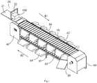
goods 100. As shown inFIGS. 1 and2 , the dual-layer linear sorter includes adelivery mechanism 10, afirst feeding mechanism 20, asecond feeding mechanism 30, aslewing mechanism 40 and adriving mechanism 50. Thedelivery mechanism 10 is ring-shaped and is configured to include an upper layer and a lower layer. The running direction of the upper layer is the first direction D1, and the running direction of the lower layer is the second direction D2, the first direction D1 is from one end of thedelivery mechanism 10 to the other end of thedelivery mechanism 10, and the second direction D2 is opposite to the first direction D1. Thefirst feeding mechanism 20 is close to the upper layer of thedelivery mechanism 10 and is docked with one end of thedelivery mechanism 10. Thesecond feeding mechanism 30 is close to the lower layer of thedelivery mechanism 10 and is docked with the other end of thedelivery mechanism 10. Theslewing mechanism 40 is connected to one end of thedelivery mechanism 10. Thedriving mechanism 50 is connected to the other end of thedelivery mechanism 10. - Where, the
driving mechanism 50 can drive thedelivery mechanism 10 to circulate in a loop between thedriving mechanism 50 and theslewing mechanism 40, a part of thegoods 100 can be delivered to the upper layer of thedelivery mechanism 10 via thefirst feeding mechanism 20, and delivered and sorted along the first direction D1, another part of thegoods 100 can be delivered to the lower layer of thedelivery mechanism 10 via thesecond feeding mechanism 30, and delivered and sorted in the second direction D2. - Therefore, the dual-layer linear sorter of the present disclosure is designed with a left-middle-right structure for the
delivery mechanism 10, the left and right structures are respectively combined with theslewing mechanism 40 and thedriving mechanism 50, the middle structure is the delivery part, and is divided into an upper layer and a lower layer, which are respectively docked with thefirst feeding mechanism 20 and thesecond feeding mechanism 30, so that the upper and lower layers can simultaneously deliver thegoods 100 to be sorted. Compared with the existing single-layer delivering sorter, the present disclosure realizes simultaneous delivering of the upper and lower layers, which doubles the sorting efficiency and improves the utilization rate of the sorter, it is especially suitable for sorting centers with narrow and long venues and large processing capacity requirements. Compared with the existing sorter with the same sorting capacity, the dual-layer linear sorter of the present disclosure can reduce its occupied space by half, thereby facilitating the miniaturization of the equipment and reducing the production cost. - In this embodiment, as shown in
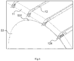
FIGS. 4-6 , thedelivery mechanism 10 may include a plurality ofdelivery units 11 and a plurality ofhinge parts 12,adjacent delivery units 11 are hinged through onehinge part 12 so that thedelivery mechanism 10 is surrounded between theslewing mechanism 40 and thedriving mechanism 50. - Where, as shown in
FIGS. 4 and6 , thehinge part 12 may include a pair ofmounting bases 121, ahinge shaft 122, ashaft sleeve 123 and analignment portion 124, amounting base 121 and ahinge shaft 122 are provided on one side of one of the twoadjacent delivery units 11, thehinge shaft 122 is detachably connected between the pair ofmounting bases 121, analignment portion 124 is provided on a side of eachmounting base 121 facing away from thehinge shaft 122, and one end of thealignment portion 124 protrudes from thedelivery unit 11 along the axial direction of thehinge shaft 122; ashaft sleeve 123 is provided on one side of one of the twoadjacent delivery units 11; thehinge shaft 122 is movably sleeved in theshaft sleeve 123, thereby enabling the twoadjacent delivery units 11 to rotate relatively. - It should be noted that the connection way of the
delivery units 11 is not limited to this, and thedelivery mechanism 10 is not limited to this, and may be a conveying belt, a chain, etc., for example. - In this embodiment, as shown in
FIGS. 1 ,3 , and6 , thedriving mechanism 50 is connected to the other end of thedelivery mechanism 10, thedriving mechanism 50 may include adriving housing 51, amotor 52 and a pair offirst turntables 53, themotor 52 and thefirst turntables 53 are accommodated in thedriving housing 51, and thedriving shaft 521 of themotor 52 is connected to the centers of thefirst turntables 53. The outer periphery of thefirst turntable 53 is provided with a plurality offirst grooves 531 that cooperate with thealignment portions 124, and the plurality ofalignment portions 124 at the other end of thedelivery mechanism 10 are respectively accommodated in thefirst grooves 531. During the operation of themotor 52, thedriving shaft 521 drives thefirst turntable 53 to rotate, and during the rotation of thefirst turntable 53, thefirst grooves 531 drive thealignment portions 124 that are aligned therewith to rotate synchronously, the aligningportion 124 enter thefirst grooves 531 aligned therewith one by one, thereby driving thedelivery unit 11 to deliver. - Where, a plurality of evenly spaced
first grooves 531 can be provided on the outer periphery of thefirst turntable 53, the distance between two adjacentfirst grooves 531 is equal to the distance between twoadjacent alignment portions 124. The number and distance of thefirst grooves 531 can be changed accordingly as needed. - In this embodiment, as shown in
FIGS. 4 ,5 , and7 , theslewing mechanism 40 is connected to one end of thedelivery mechanism 10, theslewing mechanism 40 includes aslewing housing 41, aslewing shaft 42 and asecond turntable 43, thesecond turntable 43 and theslewing shaft 42 are accommodated in theslewing housing 41, and theslewing shaft 42 is connected to the center of thesecond turntable 43, the outer periphery of thesecond turntable 43 is provided with a plurality ofsecond grooves 431 that cooperate withalignment portions 124, the plurality ofalignment portions 124 at one end of thedelivery mechanism 10 are respectively accommodated in thesecond grooves 431 correspondingly. Thedelivery mechanism 10 is delivered under the action of thedriving mechanism 50, during the movement of thedelivery unit 11, the positioningportions 124 enter thesecond grooves 431 aligned therewith one by one, thereby driving thesecond turntables 43 to rotate. - Where, the
second turntable 43 is similar to thefirst turntable 53, and the alignment relationship and principle between thesecond groove 431 and thealignment portion 124 are similar to the alignment relationship and principle between thesecond groove 431 and thealignment portion 124 of thedriving mechanism 50. - Through the transmission of the
driving mechanism 50 and theslewing mechanism 40 at both ends, the groove of the turntable is aligned with thealignment portion 124 of thetransfer unit 11, so that the delivery mechanism moves smoothly. Themotor 52 can have a variety of speeds to obtain a variety of sorting speeds of the sorter. - Where, as shown in
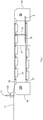
FIG. 5 , the slewinghousing 41 may include avertical plate 411, and thevertical plate 411 covers the outside of thesecond turntable 43, at a position corresponding to the slewingshaft 42, along hole 412 is opened on thevertical plate 411; theslewing mechanism 40 also includes an adjustment assembly, which includes a fixedplate 441, amovable plate 442 and anadjuster 443, the fixedplate 441 is fixed to thevertical plate 411, and the slewingshaft 42 and themovable plate 442 are connected by abearing 444, theadjuster 443 connects the fixedplate 441 and themovable plate 442, and can drive themovable plate 442 to move in the first direction D1 or the second direction D2, so that the slewingshaft 42 moves within the length range of thelong hole 412, thereby driving one end of the delivery mechanism to move in the first direction D1 or the second direction D2 relative to the other end of the delivery mechanism. - Where, the
movable plate 442 is provided with a through hole H1 located at the center of themovable plate 442 and a long adjusting hole H2 located at the periphery of themovable plate 442, thebearing 444 and the end portion of the slewingshaft 42 are arranged in the through hole HI, thebolts 445 pass through the long adjusting hole H2 and abut against thevertical plate 411, theadjuster 443 passes through the fixedplate 441 and can move relative to the fixedplate 441, and one end of theadjuster 443 is fixed to themovable plate 442. - Where, the
adjuster 443 and the fixedplate 441 may be screwed together, the relative position between theadjuster 443 and the fixedplate 441 can be changed by rotating theadjuster 443. - By pulling the other end of the
adjuster 443, themovable plate 442 can be driven to move, thereby driving the slewingshaft 42 to move back and forth, correspondingly, thesecond turntables 43 moves back and forth. Therefore, if there is a problem of slack in thedelivery mechanism 10 after long-term use, thesecond turntables 43 can be pushed in a direction away from thedriving mechanism 50, so that both the upper and lower layers of thedelivery mechanism 10 are tensioned, so that thegoods 100 can be delivered on thedelivery mechanism 10 smoothly and quickly. - As shown in
FIGS. 1 ,2 ,8 , and9 , the dual-layer linear sorter can also include a frame mechanism, the frame mechanism includes a supportingportion 61, anupper track 62, alower track 63 and a slidinggroove 64, theupper track 62 and thelower track 63 are supported by the supportingportion 61 and are used for thedelivery mechanism 10 to run, theupper track 62 is provided on the upper layer of thedelivery mechanism 10, and thelower track 63 is provided on the lower layer of thedelivery mechanism 10, both ends of theupper track 62 and both ends of theupper track 62 are respectively connected to the slewinghousing 41 and the drivinghousing 51, a plurality of slidinggrooves 64 are provided on both sides of theupper track 62 and thelower track 63 for receiving the sortedgoods 100. - Where, the
first feeding mechanism 20 includes afirst feeding section 21 and afirst scanning unit 22, thefirst feeding section 21 is docked with the other end of thedelivery mechanism 10 and extends along the extension direction of theupper track 62, a part of thefirst feeding section 21 is located on the slewinghousing 41; thefirst scanning unit 22 is located on thefirst feeding section 21, and thefirst scanning unit 22 can be installed parallel to the running direction of thedelivery mechanism 10. - The
second feeding mechanism 30 includes asecond feeding section 31, aturning section 32 and asecond scanning unit 33, one end of thesecond feeding section 31 extends beyond one side of the lower layer of thedelivery mechanism 10, the turningsection 32 is connected to the other end of thesecond feeding section 31 and extends to the upper side of the lower layer of thedelivery mechanism 10 through theturning section 32; thesecond scanning unit 33 is located between the upper layer of thedelivery mechanism 10 and the lower layer of thedelivery mechanism 10. - That is to say, the other end of the lower layer of the
delivery mechanism 10 is blocked by thedriving mechanism 50, and thesecond feeding mechanism 30 cannot directly dock with the other end of the lower layer of thedelivery mechanism 10. Therefore, thesecond feeding mechanism 30 of this embodiment is designed as the following structure: thesecond feeding section 31 first forms an angle with the sorter, and then turns an angle through theturning section 32 to extend to the upper side of the lower layer of thedelivery mechanism 10 and continue to extend along the delivering direction. - Hereinafter, the sorting principle will be explained by taking the upper layer of the
delivery mechanism 10 as an example. - The
goods 100 are transported from thefirst feeding section 21 to the upper layer of thedelivery mechanism 10, and thefirst scanning unit 22 located above scans the barcode information on thegoods 100 and inquires the destination in the warehouse management system (WMS). According to the size of thedelivery unit 11 and the number occupied, the sorter judges howmany delivery units 11 are needed to unload thegoods 100, when thedelivery mechanism 10 runs to the slidinggroove 64 of the designated destination, thedelivery units 11 under thegoods 100 acts to unload thegoods 100 to the corresponding slidinggroove 64. - The delivering principle of the lower layer of the
delivery mechanism 10 is similar to the delivering principle of the upper layer of thedelivery mechanism 10, except that the directions of the two are opposite, and the positions of the feeding mechanisms and the scanning units are different, so it is not repeated here. - In summary, the dual-layer linear sorter of the present disclosure is designed with a left-middle-right structure for the delivery mechanism, the left and right structures are respectively combined with the slewing mechanism and the driving mechanism, the middle structure is the delivery part, and is divided into an upper layer and a lower layer, which are respectively docked with the first feeding mechanism and the second feeding mechanism, so that the upper and lower layers can simultaneously deliver the goods to be sorted. Compared with the existing single-layer delivering sorter, the present disclosure realizes simultaneous delivering of the upper and lower layers, which doubles the sorting efficiency and improves the utilization rate of the sorter, it is especially suitable for sorting centers with narrow and long venues and large processing capacity requirements. Compared with the existing sorter with the same sorting capacity, the dual-layer linear sorter of the present disclosure can reduce its occupied space by half, thereby facilitating the miniaturization of the equipment and reducing the production cost.
- Although the present disclosure has been described with reference to a few typical embodiments, it should be understood that the terms used are illustrative and exemplary rather than restrictive. Since the present disclosure can be implemented in various forms without departing from the spirit or essence of the disclosure, it should be understood that the above-mentioned embodiments are not limited to any of the foregoing details, but should be interpreted broadly within the spirit and scope defined by the appended claims. Therefore, all changes and modifications falling within the scope of the claims or their equivalents shall be covered by the appended claims.
Claims (11)
- A dual-layer linear sorter, comprising:a delivery mechanism being ring-shaped and configured to comprise an upper layer and a lower layer, wherein a running direction of the upper layer is a first direction, and a running direction of the lower layer is a second direction, the first direction is from one end of the delivery mechanism to the other end of the delivery mechanism, and the second direction is opposite to the first direction;a first feeding mechanism being close to the upper layer of the delivery mechanism and being docked with one end of the delivery mechanism;a second feeding mechanism being close to the lower layer of the delivery mechanism and being docked with the other end of the delivery mechanism;a slewing mechanism being connected to one end of the delivery mechanism; anda driving mechanism being connected to the other end of the delivery mechanism;wherein the driving mechanism is configured to drive the delivery mechanism to circulate in a loop between the driving mechanism and the slewing mechanism, a part of goods are delivered to the upper layer of the delivery mechanism via the first feeding mechanism, and are delivered and sorted along the first direction, another part of the goods are delivered to the lower layer of the delivery mechanism via the second feeding mechanism, and delivered and sorted in the second direction.
- The dual-layer linear sorter according to claim 1, wherein the delivery mechanism comprises a plurality of delivery units and a plurality of hinge parts, adjacent delivery units are hinged through one hinge part.
- The dual-layer linear sorter according to claim 2, wherein the hinge part comprises a pair of mounting bases, a hinge shaft, a shaft sleeve and an alignment portion, a mounting base and a hinge shaft are provided on one side of one of the two adjacent delivery units, the hinge shaft is detachably connected between the pair of mounting bases, the alignment portion is provided on a side of each mounting base facing away from the hinge shaft, and one end of the alignment portion protrudes from the delivery units along an axial direction of the hinge shaft; the shaft sleeve is provided on one side of one of the two adjacent delivery units; the hinge shaft is movably sleeved in the shaft sleeve.
- The dual-layer linear sorter according to claim 3, wherein the driving mechanism is connected to the other end of the delivery mechanism, the driving mechanism comprises a driving housing, a motor and a pair of first turntables, the motor and the first turntables are accommodated in the driving housing, and a driving shaft of the motor is connected to centers of the first turntables, an outer periphery of each of the first turntables is provided with a plurality of first grooves that cooperate with alignment portions, and a plurality of alignment portions at the other end of the delivery mechanism are respectively accommodated in the first grooves, during an operation of the motor, the driving shaft drives the first turntables to rotate, thereby driving the delivery units to deliver.
- The dual-layer linear sorter according to claim 4, wherein a plurality of evenly spaced first grooves are provided on the outer periphery of each of the first turntables, a distance between two adjacent first grooves is equal to a distance between two adjacent alignment portions.
- The dual-layer linear sorter according to claim 4, wherein the slewing mechanism is connected to one end of the delivery mechanism, the slewing mechanism comprises a slewing housing, a slewing shaft and a second turntable, the second turntable and the slewing shaft are accommodated in the slewing housing, and the slewing shaft is connected to a center of the second turntable, an outer periphery of the second turntable is provided with a plurality of second grooves that cooperate with alignment portions, a plurality of alignment portions at one end of the delivery mechanism are respectively accommodated in the second grooves correspondingly, during a delivering process of the delivery mechanism, the delivery units drives the second turntable to rotate.
- The dual-layer linear sorter according to claim 6, wherein the slewing housing comprises a vertical plate, and the vertical plate covers the outside of the second turntable, at a position corresponding to the slewing shaft, a long hole is opened on the vertical plate; the slewing mechanism also comprises an adjustment assembly, the adjustment assembly comprises a fixed plate, a movable plate and an adjuster, the fixed plate is fixed to the vertical plate, and the slewing shaft and the movable plate are connected by a bearing, the adjuster connects the fixed plate and the movable plate, and drive the movable plate to move in the first direction or the second direction, so that the slewing shaft moves within a length range of the long hole, thereby driving one end of the delivery mechanism to move in the first direction or the second direction relative to the other end of the delivery mechanism.
- The dual-layer linear sorter according to claim 7, wherein the movable plate is provided with a through hole located at a center of the movable plate and a long adjusting hole located at a periphery of the movable plate, the bearing and an end portion of the slewing shaft are arranged in the through hole, bolts pass through the long adjusting hole and abut against the vertical plate, the adjuster passes through the fixed plate and is configured to move relative to the fixed plate, and one end of the adjuster is fixed to the movable plate, by pulling the other end of the adjuster, the movable plate is driven to move.
- The dual-layer linear sorter according to claim 6, further comprising:
a frame mechanism comprising a supporting portion, an upper track, a lower track and a sliding groove, wherein the upper track and the lower track are supported by a supporting portion and are used for the delivery mechanism to run, the upper track is provided on the upper layer of the delivery mechanism, and the lower track is provided on the lower layer of the delivery mechanism, both ends of the upper track and both ends of the upper track are respectively connected to the slewing housing and the driving housing, a plurality of sliding grooves are provided on both sides of the upper track and the lower track for receiving sorted goods. - The dual-layer linear sorter according to claim 9, wherein the first feeding mechanism comprises a first feeding section and a first scanning unit, the first feeding section is docked with the other end of the delivery mechanism and extends along an extension direction of the upper track, a part of the first feeding section is located on the slewing housing; the first scanning unit is located on the first feeding section.
- The dual-layer linear sorter according to claim 9, wherein the second feeding mechanism comprises a second feeding section, a turning section and a second scanning unit, one end of the second feeding section extends beyond one side of the lower layer of the delivery mechanism, the turning section is connected to the other end of the second feeding section and extends to an upper side of the lower layer of the delivery mechanism through the turning section; the second scanning unit is located between the upper layer of the delivery mechanism and the lower layer of the delivery mechanism.
Applications Claiming Priority (2)
| Application Number | Priority Date | Filing Date | Title |
|---|---|---|---|
| CN201910037022.8A CN111434593A (en) | 2019-01-15 | 2019-01-15 | Double-layer linear sorting machine |
| PCT/CN2020/070128 WO2020147592A1 (en) | 2019-01-15 | 2020-01-02 | Dual-layer linear sorter |
Publications (2)
| Publication Number | Publication Date |
|---|---|
| EP3912935A1 true EP3912935A1 (en) | 2021-11-24 |
| EP3912935A4 EP3912935A4 (en) | 2022-11-30 |
Family
ID=71580843
Family Applications (1)
| Application Number | Title | Priority Date | Filing Date |
|---|---|---|---|
| EP20741893.0A Pending EP3912935A4 (en) | 2019-01-15 | 2020-01-02 | Dual-layer linear sorter |
Country Status (6)
| Country | Link |
|---|---|
| US (1) | US11365066B2 (en) |
| EP (1) | EP3912935A4 (en) |
| JP (1) | JP7325513B2 (en) |
| KR (1) | KR102534415B1 (en) |
| CN (1) | CN111434593A (en) |
| WO (1) | WO2020147592A1 (en) |
Families Citing this family (4)
| Publication number | Priority date | Publication date | Assignee | Title |
|---|---|---|---|---|
| CN114633995A (en) * | 2020-12-16 | 2022-06-17 | 杭州旭辉快递智能设备有限公司 | Multilayer linear circulating conveyor and double-sided trolley thereof |
| CN114932093B (en) * | 2022-05-31 | 2023-06-16 | 瑞浦兰钧能源股份有限公司 | Bad battery pack tray equipment and battery production line |
| CN116873530B (en) * | 2023-07-31 | 2024-02-23 | 浙江应杰科技有限公司 | Double-layer crossed belt sorting equipment and use method |
| CN116729966B (en) * | 2023-08-03 | 2024-01-23 | 中国邮政集团有限公司淄博市博山区分公司 | Intelligent cloud bin logistics sorting belt conveying equipment |
Family Cites Families (17)
| Publication number | Priority date | Publication date | Assignee | Title |
|---|---|---|---|---|
| JPS6132892Y2 (en) * | 1981-02-26 | 1986-09-25 | ||
| DK155207C (en) * | 1985-08-26 | 1989-07-10 | Int Transport Syst Its | SORTING MACHINE, ISAIR FOR TASKS |
| US5284252A (en) * | 1991-11-13 | 1994-02-08 | United Parcel Service Of America, Inc. | Automatic rotary sorter |
| US5433311A (en) * | 1993-11-17 | 1995-07-18 | United Parcel Service Of America, Inc. | Dual level tilting tray package sorting apparatus |
| US5901830A (en) * | 1997-01-22 | 1999-05-11 | Electrocom Automation, L.P. | Bi-directional belt sorter |
| US6619465B1 (en) | 1999-03-31 | 2003-09-16 | Gebhardt Fördertechnik GmbH | Points for a feeding system, especially a gravity roller table |
| DE19957841A1 (en) * | 1999-12-01 | 2001-06-07 | Applimont Gmbh Software | A packaged goods selection system has a continuous transit track which utilizes both the forward and return sides to hold pallets |
| AU2003226892A1 (en) * | 2003-03-17 | 2004-10-11 | Crisplant A/S | A space adjustable conveyor with article carriers |
| AT506638B1 (en) | 2008-04-03 | 2010-05-15 | Salomon Automation Gmbh | COMMISSIONING SYSTEM AND METHOD FOR PICKING |
| JP5688737B2 (en) | 2011-02-18 | 2015-03-25 | スターテクノ株式会社 | Caterpillar type chain conveyor |
| US9409716B2 (en) * | 2014-06-13 | 2016-08-09 | Bastian Solutions, Llc | Cross belt slat sorter |
| WO2018201845A1 (en) * | 2017-05-05 | 2018-11-08 | 北京京东尚科信息技术有限公司 | Sorting trolley |
| CN106956887B (en) * | 2017-05-05 | 2022-09-30 | 北京京东乾石科技有限公司 | Vertical sorting machine |
| CN107020247B (en) * | 2017-06-01 | 2023-01-17 | 辽宁科技大学 | Full-automatic express delivery piece sorting system |
| CN208135406U (en) | 2018-01-19 | 2018-11-23 | 标杩自动化设备(东莞)有限公司 | A kind of bilayer traffic circle band automatic sorting line |
| CN109516165A (en) * | 2018-12-06 | 2019-03-26 | 沈志伟 | A kind of single-row device of upper and lower stroke automatic sorting of linear type |
| CN209701663U (en) | 2019-01-15 | 2019-11-29 | 北京京东尚科信息技术有限公司 | A kind of linear sorter of bilayer |
-
2019
- 2019-01-15 CN CN201910037022.8A patent/CN111434593A/en active Pending
-
2020
- 2020-01-02 US US17/414,557 patent/US11365066B2/en active Active
- 2020-01-02 WO PCT/CN2020/070128 patent/WO2020147592A1/en unknown
- 2020-01-02 JP JP2021535209A patent/JP7325513B2/en active Active
- 2020-01-02 KR KR1020217019221A patent/KR102534415B1/en active IP Right Grant
- 2020-01-02 EP EP20741893.0A patent/EP3912935A4/en active Pending
Also Published As
| Publication number | Publication date |
|---|---|
| EP3912935A4 (en) | 2022-11-30 |
| JP7325513B2 (en) | 2023-08-14 |
| US11365066B2 (en) | 2022-06-21 |
| US20220009724A1 (en) | 2022-01-13 |
| CN111434593A (en) | 2020-07-21 |
| JP2022514583A (en) | 2022-02-14 |
| KR20210093329A (en) | 2021-07-27 |
| KR102534415B1 (en) | 2023-05-18 |
| WO2020147592A1 (en) | 2020-07-23 |
Similar Documents
| Publication | Publication Date | Title |
|---|---|---|
| US11365066B2 (en) | Dual-layer linear sorter | |
| US20180257110A1 (en) | Package sorting transfer modules and systems and methods therefor | |
| CN112233999B (en) | Semiconductor process equipment and turntable mechanism thereof | |
| WO2022134403A1 (en) | Annular logistics line and method | |
| RU2559774C2 (en) | Data carrier transfer mechanism | |
| CN209701663U (en) | A kind of linear sorter of bilayer | |
| CA1264058A (en) | Intermittent drive for a paper supply roller | |
| KR20210112096A (en) | Wheel sorter | |
| KR102284970B1 (en) | Wheel sorter | |
| CN113968474A (en) | Balance wheel module, balance wheel machine and sorting method | |
| WO1996015965A1 (en) | Carrier device | |
| CN216420219U (en) | Carousel formula sorting device and letter sorting system | |
| KR102284967B1 (en) | Wheel sorter | |
| CN219448400U (en) | Logistics sorting and transferring device | |
| CN214516126U (en) | Scanning sorting device based on internet of things technology electric wire and cable production line MES system | |
| JP2628208B2 (en) | Paper transport device | |
| CN220536617U (en) | Logistics storage logistics conveying device | |
| CN220077568U (en) | Server disassembling line | |
| CN218578709U (en) | Side-by-side conveying device | |
| KR102307636B1 (en) | Wheel unit of wheel sorter | |
| KR102610899B1 (en) | High-speed silent sorting device | |
| CN211623961U (en) | Arc guide rail | |
| KR100424770B1 (en) | Automatic ticket issuing device | |
| US6672445B1 (en) | Working platform for assembly line | |
| JPH04345419A (en) | Inversion device |
Legal Events
| Date | Code | Title | Description |
|---|---|---|---|
| STAA | Information on the status of an ep patent application or granted ep patent |
Free format text: STATUS: THE INTERNATIONAL PUBLICATION HAS BEEN MADE |
|
| PUAI | Public reference made under article 153(3) epc to a published international application that has entered the european phase |
Free format text: ORIGINAL CODE: 0009012 |
|
| STAA | Information on the status of an ep patent application or granted ep patent |
Free format text: STATUS: REQUEST FOR EXAMINATION WAS MADE |
|
| 17P | Request for examination filed |
Effective date: 20210624 |
|
| AK | Designated contracting states |
Kind code of ref document: A1 Designated state(s): AL AT BE BG CH CY CZ DE DK EE ES FI FR GB GR HR HU IE IS IT LI LT LU LV MC MK MT NL NO PL PT RO RS SE SI SK SM TR |
|
| DAV | Request for validation of the european patent (deleted) | ||
| DAX | Request for extension of the european patent (deleted) | ||
| A4 | Supplementary search report drawn up and despatched |
Effective date: 20221028 |
|
| RIC1 | Information provided on ipc code assigned before grant |
Ipc: B07C 3/06 20060101ALI20221024BHEP Ipc: B65G 47/96 20060101ALI20221024BHEP Ipc: B65G 23/44 20060101ALI20221024BHEP Ipc: B65G 23/22 20060101ALI20221024BHEP Ipc: B65G 21/22 20060101ALI20221024BHEP Ipc: B65G 17/06 20060101ALI20221024BHEP Ipc: B65G 17/34 20060101ALI20221024BHEP Ipc: B65G 15/28 20060101ALI20221024BHEP Ipc: B65G 1/04 20060101ALI20221024BHEP Ipc: B65G 47/44 20060101ALI20221024BHEP Ipc: B65G 47/04 20060101AFI20221024BHEP |