EP3912528A1 - Cooking appliance provided with a vessel with a removable system for driving a stirring blade and method for mounting said system - Google Patents
Cooking appliance provided with a vessel with a removable system for driving a stirring blade and method for mounting said system Download PDFInfo
- Publication number
- EP3912528A1 EP3912528A1 EP21174515.3A EP21174515A EP3912528A1 EP 3912528 A1 EP3912528 A1 EP 3912528A1 EP 21174515 A EP21174515 A EP 21174515A EP 3912528 A1 EP3912528 A1 EP 3912528A1
- Authority
- EP
- European Patent Office
- Prior art keywords
- tank
- rolling bearing
- housing
- central opening
- rotation
- Prior art date
- Legal status (The legal status is an assumption and is not a legal conclusion. Google has not performed a legal analysis and makes no representation as to the accuracy of the status listed.)
- Granted
Links
- 238000010411 cooking Methods 0.000 title claims abstract description 91
- 238000000034 method Methods 0.000 title claims description 18
- 238000003756 stirring Methods 0.000 title description 11
- 238000005096 rolling process Methods 0.000 claims abstract description 96
- 238000010438 heat treatment Methods 0.000 claims description 31
- 235000013305 food Nutrition 0.000 claims description 24
- 230000000284 resting effect Effects 0.000 claims description 11
- 238000002360 preparation method Methods 0.000 claims description 6
- 238000009434 installation Methods 0.000 claims description 5
- 230000000903 blocking effect Effects 0.000 claims description 3
- 238000003825 pressing Methods 0.000 abstract description 2
- 208000031968 Cadaver Diseases 0.000 description 7
- XLYOFNOQVPJJNP-UHFFFAOYSA-N water Substances O XLYOFNOQVPJJNP-UHFFFAOYSA-N 0.000 description 6
- 230000008901 benefit Effects 0.000 description 4
- 230000006835 compression Effects 0.000 description 3
- 238000007906 compression Methods 0.000 description 3
- 239000007788 liquid Substances 0.000 description 3
- 230000000694 effects Effects 0.000 description 2
- 238000002156 mixing Methods 0.000 description 2
- 230000008569 process Effects 0.000 description 2
- 241000251468 Actinopterygii Species 0.000 description 1
- 241001465754 Metazoa Species 0.000 description 1
- 230000004913 activation Effects 0.000 description 1
- 235000010675 chips/crisps Nutrition 0.000 description 1
- 238000004140 cleaning Methods 0.000 description 1
- 230000000295 complement effect Effects 0.000 description 1
- 238000002788 crimping Methods 0.000 description 1
- 235000005911 diet Nutrition 0.000 description 1
- 230000000378 dietary effect Effects 0.000 description 1
- 238000000605 extraction Methods 0.000 description 1
- 235000019688 fish Nutrition 0.000 description 1
- 238000000227 grinding Methods 0.000 description 1
- 230000014759 maintenance of location Effects 0.000 description 1
- 235000013372 meat Nutrition 0.000 description 1
- 238000007790 scraping Methods 0.000 description 1
- 230000009466 transformation Effects 0.000 description 1
- 235000013311 vegetables Nutrition 0.000 description 1
- 238000003466 welding Methods 0.000 description 1
Images


Classifications
-
- A—HUMAN NECESSITIES
- A47—FURNITURE; DOMESTIC ARTICLES OR APPLIANCES; COFFEE MILLS; SPICE MILLS; SUCTION CLEANERS IN GENERAL
- A47J—KITCHEN EQUIPMENT; COFFEE MILLS; SPICE MILLS; APPARATUS FOR MAKING BEVERAGES
- A47J37/00—Baking; Roasting; Grilling; Frying
- A47J37/06—Roasters; Grills; Sandwich grills
- A47J37/0623—Small-size cooking ovens, i.e. defining an at least partially closed cooking cavity
- A47J37/0629—Small-size cooking ovens, i.e. defining an at least partially closed cooking cavity with electric heating elements
- A47J37/0641—Small-size cooking ovens, i.e. defining an at least partially closed cooking cavity with electric heating elements with forced air circulation, e.g. air fryers
-
- A—HUMAN NECESSITIES
- A47—FURNITURE; DOMESTIC ARTICLES OR APPLIANCES; COFFEE MILLS; SPICE MILLS; SUCTION CLEANERS IN GENERAL
- A47J—KITCHEN EQUIPMENT; COFFEE MILLS; SPICE MILLS; APPARATUS FOR MAKING BEVERAGES
- A47J27/00—Cooking-vessels
- A47J27/04—Cooking-vessels for cooking food in steam; Devices for extracting fruit juice by means of steam ; Vacuum cooking vessels
-
- A—HUMAN NECESSITIES
- A47—FURNITURE; DOMESTIC ARTICLES OR APPLIANCES; COFFEE MILLS; SPICE MILLS; SUCTION CLEANERS IN GENERAL
- A47J—KITCHEN EQUIPMENT; COFFEE MILLS; SPICE MILLS; APPARATUS FOR MAKING BEVERAGES
- A47J36/00—Parts, details or accessories of cooking-vessels
-
- A—HUMAN NECESSITIES
- A47—FURNITURE; DOMESTIC ARTICLES OR APPLIANCES; COFFEE MILLS; SPICE MILLS; SUCTION CLEANERS IN GENERAL
- A47J—KITCHEN EQUIPMENT; COFFEE MILLS; SPICE MILLS; APPARATUS FOR MAKING BEVERAGES
- A47J36/00—Parts, details or accessories of cooking-vessels
- A47J36/16—Inserts
-
- A—HUMAN NECESSITIES
- A47—FURNITURE; DOMESTIC ARTICLES OR APPLIANCES; COFFEE MILLS; SPICE MILLS; SUCTION CLEANERS IN GENERAL
- A47J—KITCHEN EQUIPMENT; COFFEE MILLS; SPICE MILLS; APPARATUS FOR MAKING BEVERAGES
- A47J36/00—Parts, details or accessories of cooking-vessels
- A47J36/24—Warming devices
-
- A—HUMAN NECESSITIES
- A47—FURNITURE; DOMESTIC ARTICLES OR APPLIANCES; COFFEE MILLS; SPICE MILLS; SUCTION CLEANERS IN GENERAL
- A47J—KITCHEN EQUIPMENT; COFFEE MILLS; SPICE MILLS; APPARATUS FOR MAKING BEVERAGES
- A47J37/00—Baking; Roasting; Grilling; Frying
- A47J37/06—Roasters; Grills; Sandwich grills
- A47J37/0623—Small-size cooking ovens, i.e. defining an at least partially closed cooking cavity
- A47J37/0664—Accessories
Definitions
- the present invention relates to cooking appliances which comprise a tank in which is positioned a removable kitchen accessory, in particular a stirring blade, the tank comprising a drive system allowing the reception and rotation of said placed kitchen accessory. inside the tank.
- the invention relates in particular to the design of the drive system of the tank, in order to allow its easy disassembly and assembly with respect to the tank.
- the invention will preferably be implemented on hot air cooking apparatus, of the hot air fryer type, which make it possible to cook food by means of a circulation of hot air in a cooking chamber of this appliance. .
- Cooking appliances of the hot air fryer type are well known to those skilled in the art. Such a cooking appliance makes it possible to greatly reduce the quantity of fat, or even to eliminate it completely, during the cooking of the food which is carried out by means of a circulation of hot air in a cooking chamber containing the food to be cooked. Thus, it is possible to consume more dietetic foods, these foods possibly being of plant or animal origin, for example chips, vegetables, meat or fish.
- Such a cooking appliance generally comprises a body and a removable tank which allows the reception of the food to be cooked.
- Food can be placed either directly in the bowl or in a basket which is itself placed in the bowl. Once the food is placed in the tank, with or without the basket, the cooking appliance can be closed to form a cooking enclosure incorporating the tank and the food.
- Hot air is then pulsed in this cooking chamber by means of a heating device and an air circulation device, the circulation of hot air in the chamber ensuring the cooking of the food.
- Such a hot-air cooking appliance further comprises a kitchen accessory, of the stirring blade type, which is positioned in the tank and makes it possible to stir the food during their cooking.
- This stirring blade is driven in rotation by means of a rotary drive system.
- the tank comprises a drive nut which is rotatably mounted on the bottom of the tank and passes through the latter, the drive nut being secured to a toothed wheel arranged under the bottom of the tank and rotating according to the same axis of rotation as said drive nut.
- a first fastening part is arranged above the bottom of the tank and a second fastening part is arranged below the tank, these two fastening parts ensuring that the toothed wheel and the nut are kept in rotation. drive on the bottom of the tank.
- the stirring blade, placed in the tank is coupled to this drive nut.
- the body of the appliance comprises a motor which drives a toothed pinion in rotation, this toothed pinion being arranged in the bottom of the cooking chamber.
- this toothed wheel meshes with the toothed pinion, the rotation of the motor thus allowing the rotation of the stirring blade in the tank.
- the first objective of the present invention is to facilitate the assembly and disassembly of the elements of the drive system of the kitchen accessory, which are present on the tank. This will first of all facilitate the cleaning of the tank by quickly dismantling the tank drive system, its reassembly also being done quickly and easily. This will also make it possible to quickly modify the cooking mode by means of the tank, as will be presented in the following description.
- a second objective of the invention is to allow rapid transformation of the tank in order to diversify its cooking methods, with or without the kitchen accessory.
- a third objective of the invention is to extend the functions of the cooking appliance so that it has more cooking modes, in order to cook various and varied recipes.
- the apparatus comprises a body provided with a cooking enclosure, a food receiving tank capable of being placed in the cooking enclosure and withdrawn therefrom.
- the body comprises a motorized device rotating a toothed pinion accessible from the cooking chamber.
- the tank comprises a bottom provided with a first central opening, a drive nut mounted in rotation about an axis of rotation perpendicular to the bottom of the tank and communicating with the interior volume of the tank through the first central opening and a toothed wheel mounted in rotation along the axis of rotation below the base and secured to the drive nut.
- the toothed wheel meshes with the toothed pinion when the bowl is placed in the cooking chamber.
- the drive nut can communicate with the interior volume of the tank through the first central opening, either by passing through said first central opening to position itself partly above the bottom of the tank, or by remaining entirely below the bottom of the tank, while being accessible from the interior volume of the tank, through the first central opening.
- the tank comprises a removable casing placed below the first central opening and configured to bear against the underside of the bottom of the tank and to receive and hold the toothed wheel and the nut. drive, mounted in rotation along the axis of rotation.
- the tank comprises a removable rolling bearing placed in the interior volume of the tank, the rolling bearing being provided with a body and a tube. The body is configured to pass through the first opening center and rest against the top of the bottom of the tank and to come into engagement with the casing thanks to an assembly system, so that the casing and the body of the rolling bearing remain pressed on either side against the bottom of the tank.
- the tube extends the body upwards into the internal volume of the tank, above the first opening, and is able to receive in rotation along the axis of rotation a kitchen accessory placed in the internal volume of the tank.
- the drive nut engages at least in the body of the rolling bearing when the housing and the rolling bearing are engaged, so that said drive nut is able to mesh with the kitchen accessory, configured to this effect, when said kitchen accessory is engaged on the tube.
- the user can easily dismantle and reassemble the elements of the drive system on the tank; it suffices to accommodate the toothed wheel attached to the drive nut inside the casing, to position the casing resting against the underside of the bottom of the tank by positioning the drive nut opposite the first central opening , or even by inserting the upper end of said drive nut into the first central opening, to position the rolling bearing in the internal volume of the tank and to introduce the body of the rolling bearing into the first central opening until for said body to come to rest against the top of the bottom of the tank, then to perform the assembly to hold the housing and the body of the rolling bearing in engagement by means of the assembly system, the housing and the body of the rolling bearing pressing on either side of the tank bottom. Disassembly is carried out by a reverse procedure, by disassembling the body of the rolling bearing and the housing to then release the rolling bearing from above the tank and the housing, with the toothed wheel and the drive nut, from the underside of the tank.
- the apparatus comprises a plate comprising a second central opening allowing the passage of the tube of the rolling bearing when said plate is placed in the interior volume of the tank.
- means for blocking the rotation of the plate along the axis of rotation are arranged between said plate and the body of the rolling bearing.
- the tray remains perfectly stationary in the tank during the rotation of the kitchen accessory which is positioned above the tray in the interior volume of the tank, when using the tray and the kitchen accessory, depending on the cooking mode used on the cooking appliance.
- a support system is implemented between the tray and the tank to maintain a spacing between the bottom of the tank and the tray.
- This spacing will allow in particular the addition of water in the bottom of the tank, below the plate, as will appear in the remainder of the description.
- the top comprises a base configured to bear on the bottom of the tank and support the top with said spacing relative to the bottom of the tank.
- this support system for example support lugs arranged on an internal contour of the tank, the plate resting on said support lugs while preserving said spacing with respect to the bottom of the tank. tank.
- the locking means are implemented by the second central opening on the plate which has a polygonal shape, preferably a square shape, and by a contour element on the body of the bearing bearing, the contour element surrounding a lower portion of the tube and having a polygonal shape, preferably a square shape, corresponding to that of the second central opening, so that the second central opening engages the element of contour when positioning the plate in the interior volume of the tank, thus ensuring said blocking.
- Variants of locking means can still be envisaged within the framework of the invention.
- the tank comprises a seal positioned at the periphery of the first central opening above the bottom of the tank, the body of the rolling bearing comprising a configured disc. so that the seal is compressed between the top of the bottom of the tank and said disc when the rolling bearing is in engagement with the housing.
- This seal will advantageously allow the introduction of liquid into the bottom of the tank, for example water.
- This seal compressed between the bottom of the tank and the disc on the body of the rolling bearing, also guarantees the locking in rotation along the axis of rotation, of the housing and of the rolling bearing in engagement with one another. in the other thanks to the assembly system.
- the assembly system between the casing and the body of the rolling bearing is a bayonet system.
- This bayonet system will make it possible to assemble between the casing and the body of the rolling bearing by carrying out more or less a rotation of a quarter of a turn between these two elements along the axis of rotation, which ensures a quick between the housing and the rolling bearing.
- Other assembly systems by performing a quarter-turn rotation could be envisaged, in particular a quarter-turn screwing.
- Other assembly systems could also be envisaged, for example a system for snapping the body of the rolling bearing onto the housing, a maneuvering member on the body of the rolling bearing allowing it to unclip from the housing.
- the casing comprises an upper tubular portion provided with an external shoulder.
- This upper tubular portion is configured to fit into the first central opening until a rim in the bottom of the tank, defining said first central opening, comes to rest against said external shoulder.
- the body of the rolling bearing comprises a lower tubular portion configured to engage in the upper tubular portion of the housing, the assembly system being implemented between an outer contour of the lower tubular portion of said body and a internal contour of the upper tubular portion of the housing.
- the drive nut comprises a tubular element which is mounted in a pivot connection along the axis of rotation inside a bore arranged on the lower tubular portion of the rolling bearing housing.
- said bore comprises a bottom bearing against an upper end of this tubular element when the body of the rolling bearing is in engagement with the housing; thus, the toothed wheel and the drive nut are immobilized in translation along the axis of rotation by virtue of the housing and the rolling bearing assembled with one another.
- the casing comprises a bottom provided with a cylindrical stud.
- the drive nut comprises a cylindrical housing which engages on the cylindrical stud for mounting in a pivot connection along the axis of rotation of the drive nut and of the toothed wheel with respect to the housing.
- a positioning system is arranged between the casing and the bottom of the tank to orient the casing around the axis of rotation in a defined position.
- This has the advantage of ensuring precise engagement of the toothed wheel with the toothed pinion when inserting the tank into the cooking chamber.
- This also has the advantage of participating in the locking in rotation along the axis of rotation, of the housing relative to the bottom of the tank, in addition to the seal compressed between the bottom of the tank and the disc of the bearing body.
- the positioning system comprises a plate arranged on the housing and provided with at least one orifice, preferably three orifices.
- the positioning system comprises at least one stud arranged under the bottom of the tank, preferably three studs, said at least one stud engaging in said at least one orifice when the housing is placed under the bottom. of the tank according to said defined position.
- the casing comprises a contour provided with a window allowing the passage of a part of the toothed wheel for its meshing with the toothed pinion when placing the bowl in the cooking chamber.
- the apparatus comprises a removable plug configured to be placed in place of the rolling bearing when the latter is withdrawn from the tank.
- the cap is configured to pass through the first central opening, resting against the top of the bottom of the tank and to engage with the casing thanks to a second assembly system identical to the first assembly system described above, so that the casing and the cap remain pressed on either side against the bottom of the tank.
- This implementation makes it possible to use the tank without the rolling bearing and without the accessory, by placing the plug in the bottom of the tank. This will allow food to be placed in the tank which has a substantially flat bottom over its entire surface.
- the apparatus comprises a first heating device making it possible to heat the food receiving tank by thermal conduction when said tank is placed in the cooking chamber. This will heat up liquids in the tank, for example water.
- the appliance is a hot air cooking appliance which comprises a second heating device making it possible to heat the air and a circulation device allowing circulation of the heated air in the tank. receiving food when placed in the cooking chamber.
- the cooking methods can be extended by means of the apparatus according to the invention which has the characteristics of a traditional hot air cooking appliance, with in addition a device for heating the tank by thermal conduction.
- a device for heating the tank by thermal conduction in addition to the rapid assembly and disassembly of the drive system on the tank
- variants of the cooking appliance could include only the first device for heating the tank by thermal conduction or only the second air heater and air circulation device.
- the cooking appliance comprises a control circuit arranged to control the first heating device of the tank by thermal conduction, once the vat has been placed in the cooking chamber and according to the culinary preparation mode selected by the user.
- This control circuit also controls the second air heating device and the heated air circulation device, once the tank has been placed in the cooking chamber and according to the culinary preparation mode selected by the user. .
- This control circuit also controls the motorized device rotating the toothed pinion.
- the appliance comprises a kitchen accessory consisting of a stirring blade.
- Other kitchen accessories could be considered, for example knives for chopping or mixing food in the tank, or even a mixer.
- the body comprises a base and a drawer removably mounted on the base between an engaged position where the cooking enclosure is closed and an unobstructed position where the cooking enclosure is open, the tank being secured to the drawer.
- the body would include a cover allowing the vessel to be housed in the cooking chamber, with or without the basket, the closure of the cover allowing the closure of the. cooking chamber.
- the cooking apparatus comprises a removable basket configured to be placed in and removed from the tub.
- This basket can be placed in the tank instead of the tray.
- This basket could also be placed on the tray itself placed in the tank.
- said method comprises prior to the positioning of the kitchen accessory on the tube of the rolling bearing, a step of positioning the tray in the internal volume of the tank by introducing the tube through the second central opening of said plate, then a step of placing the locking means between said plate and the body of the rolling bearing.
- a step prior to positioning the casing consists in positioning said seal around the first central opening, on top of the bottom of the tank.
- the latter comprises, prior to positioning the plug, a step of removing the toothed wheel and the drive nut from the casing.
- This step will be implemented when the drive nut enters the interior volume of the tank through the first central opening. In fact, the removal of the toothed wheel and of the drive nut is necessary in this case in order to be able to put the plug in place.
- This additional step will not be necessary when the drive nut is designed so that its upper end remains below the bottom of the casing, positioned opposite the first opening to communicate with the interior volume of the tank, in order to ensure its clutch with the kitchen accessory when it is placed in the bowl.
- This step of removing the toothed wheel and the drive nut may optionally be preceded by a step of disengaging the casing from below the bottom of the tank, then followed by a step of repositioning the empty casing resting against the below the bottom of the tank, with a defined position.
- removing the drive nut and the toothed wheel by passing them through the first central opening on the bottom of the tank, from the interior volume of this tank, when the diameter of this first central opening is sufficient. large to fit the drive nut and toothed wheel.
- appliance is used to denote the cooking appliance according to the invention.
- the apparatus 1 comprises a body 2 and a drawer 3.
- the drawer 3 is removable from the body 2.
- the body 2 comprises in its upper part 2a a heating block 4 and in its lower part 2b a base 5.
- a cooking enclosure 6 At the inside this base 5 is defined a cooking enclosure 6.
- the drawer 3 comprises a front 7, a handling handle 8 and a tank 9 allowing the reception of the food to be cooked; when the drawer 3 is placed on the base 5 of the body 2, the tank 9 is housed in the cooking chamber 6 which is closed by means of the front 7.
- the drawer 3 is extracted by pulling it towards the front relative to the body 2, which makes it possible to release the tank 9 from the cooking chamber 6.
- the heating unit 4 allows hot air to circulate downwards in the direction of the cooking chamber 6 of so that when the drawer 3 is placed on the base 5 of the body 2, this hot air circulates in the cooking chamber 6 and in the tank 9.
- the heating unit 4 comprises an air inlet 10, a heating device 11 of the resistive type which makes it possible to heat the circulating air and a circulation device 12 of the fan type which makes it possible to circulate the air and propel it into the cooking chamber 6, passing first through said heating device 11 from the air.
- the appliance 1 further comprises a control circuit (not illustrated) which makes it possible to control the heating device 11 and the circulation device 12 when the drawer 3 is placed on the base 5 of the body 2 and according to the cooking program. selected on a selection keyboard (not shown) arranged on said body 2.
- the device 1 implemented according to this preferred design mode can also make it possible to heat the tank 9 by thermal conduction when the latter is placed in the cooking chamber 6, which makes it possible to extend the functions of this apparatus 1, for example by cooking liquids contained in tank 9, or even steam cooking by placing in this tank 9 a basket (not shown) or a tray (described below) and water in a bottom 13 of the tank 9, the basket or the tray being removably placed in the tank 9 and receiving food to be cooked.
- a basket not shown
- a tray described below
- the presence of such a removable basket is already known on traditional hot air cooking appliances.
- Different designs of the device 1 can be envisaged for the implementation of this heating of the tank 9 by thermal conduction.
- an additional heating device 14 is fixed under the bottom 13 of the tank 9 and ensures the heating of the tank 9 by thermal conduction.
- the attachment of the additional heating device 14 under the bottom 13 of the tank 9 is carried out for example by crimping or by welding; one could also provide fixing flanges (not shown).
- the additional heating device 14 is directly in contact with the bottom 13 of the tank 9, according to this first design mode, but one could envisage a variant according to which a slight spacing would be preserved between the additional heating device 14 and the bottom 13 of the tank 9, by means of suitable fixing brackets.
- the additional heating device 14 comprises a resistive electric member 15 which has an open circular shape with two ends 15a, 15b which are curved downwards, as illustrated in FIG. figure 3 .
- These two ends 15a, 15b each comprise a conductive pin 16, 17.
- the cooking chamber 6 of the body 2 has a bottom 18 which comprises two grooves 19, 20 which are arranged in correspondence with the two ends 15a, 15b of the resistive electrical member 15 so that the two conductive pins 16, 17 engage respectively in these two grooves 19, 20 when the tank 9 is engaged in the cooking chamber 6, when placing the drawer 3 on the body 2.
- the rear ends 19a, 20a of the grooves 19, 20 each comprise a conductive connector 21, 22 with flexible and conductive strips.
- the two conductive pins 16, 17 are respectively plugged into the conductive connectors 21, 22 by clamping between their two slats.
- These two conductive connectors 21, 22 are connected to the device control circuit 1; thus, the control circuit also allows the control of additional heating device 14 when the drawer 3 is placed on the base 5 and according to the cooking program selected by the user on the selection keyboard.
- the additional heating device 14 is no longer arranged under the bottom 13 of the tank 9 as in the case of the aforementioned first design mode, but above the bottom 18 of the cooking chamber 6.
- the additional heating device heater 14 comprises a resistive electric member 23 arranged in a coil so as to form two circular forks 24, 25 whose ends 24a, 25a are spaced from each other and define a passage 26.
- the bottom 13 of the tank 9 is positioned with a slight spacing above the resistive electric member 23, which also makes it possible to heat the bottom 13 of the tank 9 by thermal conduction.
- the two ends 23a, 23b of the resistive electric member 23 are connected to the control circuit which makes it possible to control the activation of said resistive electric member 23 when the drawer 3 is placed on the base 5 and according to the cooking program selected by the user .
- the base 5 of the body 2 comprises a compartment 27 arranged under the bottom 18 of the cooking chamber 6.
- This compartment 27 makes it possible in particular to accommodate an electric motor 28 therein allowing the drive in rotation along a vertical axis X1 of a toothed pinion 29.
- the grooves 19, 20 on the bottom 18 of the cooking chamber 6 are also placed in the thickness of this compartment 27, the electric motor 28 and the toothed pinion 29 being positioned between these two grooves 20, 21.
- the electric motor 28 is controlled by the control circuit according to the cooking program selected by the user.
- the bottom 18 of the cooking enclosure 6 comprises in its rear part 18a, between the two grooves 19, 20, and at the level of the two conductive connectors 21, 22, a housing 30 arranged protruding from said bottom 18, the housing 30 receiving the toothed pinion 29.
- This housing 30 has at the front a window 31, through which slightly protrudes a front part 29a of the toothed pinion 29 so that it communicates with the cooking enclosure 6.
- the housing 30 receiving the toothed pinion 29 with its front part 29a which protrudes slightly from the window 31.
- the resistive electric member 23 is positioned around the housing 30 so that the front part 29a of the toothed pinion 29 is accessible by passing through the passage 26 left between the two ends 24a, 25a of the forks 24, 25 of said resistive electric member 23.
- the following description relates to a drive system 32 of a kitchen accessory 33, implemented on the tank 9.
- This drive system 32 will be implemented both for the tank 9 illustrated in figure 3 and adapted to the body 2 of the device 1 illustrated in figure 2 , that for the tank adapted to the body 2 of the device 1 illustrated in figure 19 .
- the tank 9 comprises under the central part of its bottom 13 a casing 34 which comprises at the rear of its outline 35 a window 36.
- a toothed wheel 37 is mounted in rotation about an axis X2 perpendicular to the bottom 13 of the tank 9 , this axis X2 being parallel to the vertical axis X1 when the slide 3 is placed on the base 5 of the body 2.
- This toothed wheel 37 is housed in the housing 38 and has its rear part 37a which protrudes slightly from the window 36.
- the rear part 37a of the toothed wheel 37 engages with the front part 29a of the pinion 29, as shown in the figure. figure 4 .
- the actuation of the electric motor 28 thus makes it possible to drive the toothed wheel 37 in rotation along the axis of rotation X2.
- the resistive electric member 15 is arranged around the casing 34 under the bottom 13 of the tank 9, substantially at the periphery of said bottom 13, the two conductive pins 16, 17 being arranged at the rear of the tank 9, in the extension of the window 36 of the casing 34.
- the passage 26 left between the two ends 24a, 25a of the forks 24, 25 of the resistive electric member 23 is dimensioned to allow the introduction of the housing 34 between said ends 24a, 25a, so as to engage the toothed wheel 37 with the toothed pinion 29.
- the toothed wheel 37 is subject to a drive nut 38, the latter forming a one-piece part 39.
- This one-piece part 39 comprises on its lower face 40 a cylindrical housing 41.
- This one-piece part 39 also comprises a tubular element 42 which extends upwardly above the toothed wheel 37, the drive nut 38 being housed inside this tubular element 42 and projecting upwardly vis-à-vis the latter.
- the casing 34 comprises in its upper part 34a a plate 43 of substantially triangular shape which comprises three orifices 44 arranged respectively in the three corners of the plate 43. These three orifices 44 are intended to receive respectively three studs 97 (one of which is illustrated on the figure 17 ) arranged under the bottom 13 of the tank 9, when the housing 34 is pressed against the underside of said bottom 13 of the tank 9.
- the bottom 45 of the housing 34 comprises a cylindrical stud 46 which extends upwards and which receives the cylindrical housing 41 of the one-piece part 39 when the latter is placed in the housing 34, as shown in the figures.
- the casing 34 comprises an upper tubular portion 47 provided with an external shoulder 48, the plate 43 being positioned at the level of this external shoulder 48.
- the bottom 13 of the tank 9 comprises an insert part 49 of annular shape provided with 'an opening central 50 of cylindrical shape having for axis the second axis of rotation X2.
- the housing 34 When the housing 34 is placed under the bottom 13 of the tank 9, its upper tubular portion 47 fits into the central opening 50 and the outer shoulder 48 bears against a rim 51 present on the insert part 49 , this rim 51 defining said central opening 50.
- the drive nut 38 extends upward along the axis X2 and passes through the central opening 50, the upper end portion 38a of this nut d 'drive 38 coming to be placed in the internal volume 52 of the tank 9.
- the tank 9 comprises a rolling bearing 53 which has a longitudinal axis X4 coincident with the axis of rotation X2 when said rolling bearing 53 is mounted on the bottom 13 of the tank 9.
- This rolling bearing 53 comprises a body 54 and a tube 55 extending said body 54 upwards, along the longitudinal axis X4.
- the body 54 comprises a disc 56 and a lower tubular portion 57 which extends downward from said disc 56, along the longitudinal axis X4.
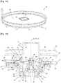
- the disc 56 has on its lower face 58 four protruding elements 59 of circular shape, spaced apart from one another and arranged around the lower tubular portion 57, as shown in the figures. figures 9 and 10 .
- the lower tubular portion 57 comprises on its outer contour 60 four legs 61 of circular shape and uniformly distributed around said lower tubular portion 57.
- the upper tubular portion 47 of the casing 34 comprises on its internal contour 62 four notches 63 of circular and uniform shape. distributed around said upper tubular portion 47.
- the four tabs 61 and the four notches 63 make it possible to produce a bayonet assembly system between the lower tubular portion 57 of the body 54 of the rolling bearing 53 and the upper tubular portion 47 of the housing 34, by introducing the lower tubular portion 57 into the upper tubular portion 47 to engage the tabs 61 in the respective notches 63, then by rotating the rolling bearing 53 with respect to the housing 34, along the axis of rotation X2 when said elements are positioned on the bottom 13 of the tank 9, which makes it possible to move said legs 61 so us circular stops 64 disposed in the continuity of said notches 63 on the internal contour 62 of said portion upper tubular 47, in order to keep the body 54 of the rolling bearing 53 in engagement with the housing 34.
- the tabs 61, the notches 63 and the circular stops 64 thus form a bayonet system.
- the insert part 49 on the bottom 13 of the tank 9 comprises a shouldered part forming an annular flattened cavity 65 at the periphery of the rim 51 which delimits the central opening 50 on said bottom 13 of the tank 9.
- This flattened cavity 65 allows the reception of a seal 66 which is preferably an O-ring.
- This seal 66 is positioned between the upper face 67 of the flattened cavity 65 and the lower face 58 of the disc 56 present on the body 54 of the rolling bearing 53.
- This seal 66 is positioned around the protruding elements 59.
- the tank 9 comprises a plate 68 which is removable and is positioned in the interior volume 52 of the tank 9.
- This plate 68 comprises a central opening 69 which has a square shape.
- the plate 68 comprises under its lower face 70 a base 71 which rests on the bottom 13 of the tank 9.
- the body 54 of the rolling bearing 53 comprises a contour element 72 which extends upwards above the disc. 56 and is positioned around the lower end portion 73 of the tube 55.
- This contour member 72 has a square shaped cross sectional area sized to engage with the central opening 69 having a complementary square shape.
- the lower tubular portion 57 of the body 54 of the rolling bearing 53 comprises a bore 74, the bottom 75 of which is formed by the lower end 55a of the tube 55 of said rolling bearing 53.
- This bore 74 is rotated along the axis of rotation X2, the tubular element 42 of the one-piece piece 39, the upper end 42a of this tubular element 42 abutting against the lower end 55a of the tube 55 when said body 54 is engaged with the housing 34.
- the one-piece part 39 is mounted to rotate along the axis X2, with the housing 34 thanks to the cylindrical stud 46 in the bottom 45 of the housing 34 and to the cylindrical housing 41 on said one-piece part 39, on the one hand, and thanks to the bore 74 and to the tubular element 42, on the other hand.
- the one-piece part 39 is blocked in translation along the axis of rotation X2 between the upper face 76 of the cylindrical stud 46 on which rests on the bottom 77 of the cylindrical housing 41, on the one hand, and the lower end 55a of the tube 55 on which rests the upper end 42a of the tubular element 42.
- the appliance 1 comprises a kitchen accessory 33 of the stirring blade type.
- This kitchen accessory 33 comprises a body 78 which extends along a longitudinal axis X5 coincident with the axis of rotation X2 when said kitchen accessory 33 is inserted on the tube 55 of the rolling bearing 53.
- the body 78 comprises a bell. outer 79 and an inner tube 80.
- the inner tube 80 passes through the tube 55 of the rolling bearing 53 passing through its upper opening 81, the lower end portion 82 of the inner tube 80 being received in the tubular element 42 of the one-piece piece 39, itself inserted into the lower tubular portion 57 of the body 54 of the rolling bearing 53, so that said lower end portion 82 engages with the drive nut 38.
- This lower end portion 82 comprises internal splines 83 which are in engagement with teeth 84 on the drive nut 38, so as to effect said engagement of the drive nut 38 with the inner tube 80 of the attachment kitchen 33.
- the tube 55 of the rolling bearing 53 is housed in the outer bell 79, the lower edge 85 of this outer bell 79 being positioned in abutment against an upper face 86 of the plate 68 when the latter is placed in the volume interior 52 of the tank, as specified above, prior to the installation of the kitchen accessory 33.
- the kitchen accessory 33 will be used in the presence of the plate 68, the stirring blade 87 of this kitchen accessory 33 scraping the upper face 86 of the plate 68.
- the assembly of the tank 9 with the drive system 32 and the kitchen accessory 33 is carried out as follows: the one-piece piece 39 is first placed in the housing 34 by engaging the cylindrical housing 41 on the stud cylindrical 46, then the casing 34 is placed under the bottom 13 of the tank 9, the pins 97 on the underside 88 of the said bottom 13 being engaged in the respective holes 44 on the plate 43 of the casing 34 and the upper tubular portion 47 of the casing 34 is engaged in the central opening 50 of the bottom 13 until the outer shoulder 48 of the casing 34 bears against the rim 51 of this central opening 50. The casing 34 is then in a defined position, locked in rotation along the axis of rotation X2, resting under the bottom 13 of the tank 9.
- the seal 66 is placed on the upper face 67 of the flattened cavity 65 present on the insert part 49 arranged on the bottom 13 of the tank 9, then the rolling bearing 53 is inserted é in the internal volume 52 of the tank 9 and the lower tubular portion 57 of the body 54 of said rolling bearing 53 is inserted into the central opening 50 until the elements protrusions 59 under the disc 56 of said body 54 bear against the upper face 67 of the flattened cavity 65, the seal 66 thus being slightly compressed between the flattened cavity 65 and the disc 56.
- the insert 49 is pressed on the underside by the housing 34 and on the top by the body 54 of the rolling bearing 53, which can then be assembled using the bayonet assembly system, by a rotation of the rolling bearing 53 according to the 'axis of rotation X2 vis-à-vis the casing 34, said rotation making it possible to move the tabs 61, initially placed in the notches 63, under the circular stops 64, which maintains the casing 34 in engagement with the body 54 of the bearing 53 by pinching the insert piece 49 and, thus, blocks the rotation along the axis of rotation X2 of the rolling bearing 53 vis-à-vis the bottom 13 of the tank 9.
- the compression of the seal 66 between the insert piece 49 and the disc 56 also participates alement said locking in rotation of the rolling bearing 53 vis-à-vis the bottom 13 of the tank 9.
- the plate 68 is placed in the internal volume 52 of the tank 9 by inserting its central opening 69 (of square shape) on the tube 55 of the rolling bearing 53 then on the contour element 72 (of square shape) of the body 54 of the rolling bearing 53, the base 71 of the plate 68 coming to rest on the bottom 13 of the tank 9, as shown in figure 1 .
- the plate 68 is locked in rotation along the axis of rotation X2 inside the tank 9.
- the kitchen accessory 33 is then placed in the tank 9, by engaging the body 78 of this kitchen accessory 33 on the tube 55 of the rolling bearing 53, the lower end portion 82 of the inner tube 80 then engaging with the drive nut 38.
- the disassembly of the drive system 32 is carried out by a reverse procedure.
- the tank 9 can be used without the plate 68 and without the rolling bearing 53, by placing a plug 89 in place of said rolling bearing 53, this plug 89 ensuring the closing of the bottom 13 of the tank 9.
- the plug 89 comprises a design similar to that of the body 54 of the rolling bearing, that is to say with a lower tubular portion 90 whose design is similar to the lower tubular portion 57 of said body 54.
- the outer contour 91 of the lower tubular portion 90 of the cap 89 comprises four tabs (not shown) similar to the four tabs 61 for the implementation of a bayonet assembly system between the cap 89 and the housing 34, in order to ensure the retention of the cap 89 for the 'closing the central opening 50 on the bottom 13 of the tank 9.
- This plug 89 also comprises a disc 92 similar to the disc 56 on the body 54 of the rolling bearing 53, the disc 92 however completely closing the upper end 90a of the lower tubular portion 90 of said stopper 89.
- the disc 92 of the stopper 89 comprises on its lower face 93 four protruding elements 94 of circular shape similar to the four protruding elements 59 on the disc 56 of the body 54 of the rolling bearing 53.
- protrusions 94 of the plug 89 press on the upper face 67 of the flattened cavity 65 of the insert part 49 when the plug 89 is assembled with the housing 34 by virtue of the bayonet assembly system.
- the seal 66 is also compressed between the upper face 67 of said flattened cavity 65 and the lower face 93 of the disc 92 of the plug 89. Since the upper end portion 38a of the drive nut 38 passes through it. 'central opening 50 on the bottom of the tank 9 and is placed in the internal volume 52 of said tank 9, the one-piece piece 39 must be removed from the housing 34 before the fitting of the cap 89, as shown in the figures 17 and 18 .
- the kitchen accessory 33 When placing the plug 89 on the tank 9, the kitchen accessory 33 is first removed, then the plate 68 and finally the rolling bearing 53.
- the housing 34 can then be released from the bottom 13 of the tank 9 for extracting the one-piece piece 39; in this case, the casing 34 is then repositioned in abutment under the bottom 13 of the tank 9, as before for the assembly of the rolling bearing 53. It could however be envisaged to extract the one-piece part. 39 of the casing 34 while maintaining the casing 34 in abutment under the bottom 13 of the tank 9, the extraction of the one-piece part 39 then taking place through the central opening 50, passing through the interior volume 52 of the tank 9.
- the seal 66 is placed on the upper face 67 of the flattened cavity 65, then the plug 89 is inserted into the tank 9 and the lower tubular portion 90 of said plug 89 is inserted into the central opening 50 until in that the protruding elements 94 under the disc 92 of said plug 89 come to bear against the upper face 67 of said flattened cavity 65, the seal 66 thus being compressed between the flattened cavity 65 and the disc 92. In this position.
- the insert part 49 is pressed on the underside by the casing 34 and on the top by the plug 89, which can then be assembled using the bayonet assembly system, by a rotation of the plug 89 along the axis of rotation X2 with respect to the housing 34, said rotation pe rmitting to move the tabs (not shown), initially placed in the notches 63, under the circular stops 64, thus maintaining the housing 34 in engagement with the plug 89 by pinching the insert part 49, which blocks the rotation according to the 'axis of rotation X2 of the cap 89 with respect to the bottom 13 of the tank 9.
- the compression of the seal 66 between the insert part 49 and the disc 89 also participates in said locking in rotation of the cap 89 screw -with respect to the bottom 13 of the tank 9.
- the removal of the stopper 89 is carried out by a reverse procedure.
- This design of the apparatus 1 has the advantage of making various and varied culinary preparations by means of the heating device 11 of the air and of the air circulation device 12, on the one hand, and of the additional device of heating 14 of the tank 9 by thermal conduction, on the other hand.
- these culinary preparations it is for example possible to put water in the bottom 13 of the tank 9, below the plate 68 on which the food is positioned, and to heat the water by means of the additional device of heater 14, which makes it possible to steam the food placed on the plate 68, this food being able to be stirred by means of the kitchen accessory 33 and possibly undergo a second cooking with hot air by means of the heating device 11 and the air circulation device 12.
- the base 71 on the plate 68 makes it possible to maintain a spacing 95 between the bottom 13 of the tank 9 and the lower face 70 of the plate 68.
- support lugs (not shown) could be provided on the internal contour 96. of the tank 9 and making it possible to support the plate 68 in order to implement said spacing 95.
Landscapes
- Engineering & Computer Science (AREA)
- Food Science & Technology (AREA)
- Food-Manufacturing Devices (AREA)
Abstract
L'invention concerne un appareil de cuisson comprenant une cuve amovible qui comprend un fond (13) muni d'une ouverture (50), une noix d'entraînement (38) communiquant avec la cuve au travers de l'ouverture (50) et assujettie à une roue dentée (37) montée en-dessous du fond (13). La cuve (9) comprend un carter (34) amovible placé en-dessous de l'ouverture (50) et prenant appui contre le fond (13) pour maintenir en rotation la roue dentée (37) et la noix d'entraînement (38). La cuve (9) comprend un palier de roulement (53) amovible placé dans la cuve et muni d'un corps (54) et d'un tube (55). Le corps (54) prend appui contre le dessus du fond (13) et vient en prise avec le carter (34), le carter (34) et le corps (54) pressant de part et d'autre le fond (13) de la cuve. Le tube (55) prolonge le corps (54) vers le haut dans la cuve et reçoit en rotation un accessoire de cuisine (33). La noix d'entraînement (38) s'engage dans le palier de roulement (53) et engrène avec l'accessoire de cuisine (33).The invention relates to a cooking appliance comprising a removable bowl which includes a base (13) with an opening (50), a drive nut (38) communicating with the bowl through the opening (50) and secured to a toothed wheel (37) mounted below the base (13). The tank (9) comprises a removable casing (34) placed below the opening (50) and bearing against the bottom (13) to keep the toothed wheel (37) and the drive nut (38) in rotation. ). The tank (9) comprises a removable rolling bearing (53) placed in the tank and provided with a body (54) and a tube (55). The body (54) bears against the top of the base (13) and engages with the casing (34), the casing (34) and the body (54) pressing on either side the base (13) of tank. The tube (55) extends the body (54) upwards into the tank and rotates a kitchen accessory (33). The drive nut (38) engages the rolling bearing (53) and meshes with the kitchen accessory (33).
Description
La présente invention concerne les appareils de cuisson qui comprennent une cuve dans laquelle est positionné un accessoire de cuisine amovible, notamment une pale de brassage, la cuve comportant un système d'entraînement permettant la réception et l'entraînement en rotation dudit accessoire de cuisine placé à l'intérieur de la cuve. L'invention porte notamment sur la conception du système d'entraînement de la cuve, afin de permettre son démontage et son montage aisément vis-à-vis de la cuve.The present invention relates to cooking appliances which comprise a tank in which is positioned a removable kitchen accessory, in particular a stirring blade, the tank comprising a drive system allowing the reception and rotation of said placed kitchen accessory. inside the tank. The invention relates in particular to the design of the drive system of the tank, in order to allow its easy disassembly and assembly with respect to the tank.
L'invention sera préférentiellement mise en oeuvre sur des appareil de cuisson à air chaud, du type friteuse à air chaud, qui permettent de réaliser une cuisson des aliments au moyen d'une circulation d'air chaud dans une enceinte de cuisson de cet appareil.The invention will preferably be implemented on hot air cooking apparatus, of the hot air fryer type, which make it possible to cook food by means of a circulation of hot air in a cooking chamber of this appliance. .
Les appareils de cuisson du type friteuse à air chaud sont bien connus de l'homme du métier. Un tel appareil de cuisson permet de réduire fortement la quantité de matière grasse, voire de la supprimer complètement, lors de la cuisson des aliments qui s'effectue grâce à une circulation d'air chaud dans une enceinte de cuisson contenant les aliments à cuire. Ainsi, il est possible de consommer des aliments plus diététiques, ces aliments pouvant être d'origine végétale ou animale, par exemple des frites, des légumes, de la viande ou du poisson.Cooking appliances of the hot air fryer type are well known to those skilled in the art. Such a cooking appliance makes it possible to greatly reduce the quantity of fat, or even to eliminate it completely, during the cooking of the food which is carried out by means of a circulation of hot air in a cooking chamber containing the food to be cooked. Thus, it is possible to consume more dietetic foods, these foods possibly being of plant or animal origin, for example chips, vegetables, meat or fish.
Un tel appareil de cuisson comprend généralement un corps et une cuve amovible qui permet la réception des aliments à cuire. Les aliments peuvent être placés soit directement dans la cuve soit dans un panier qui est lui-même placé dans la cuve. Une fois les aliments disposés dans la cuve, avec ou sans le panier, l'appareil de cuisson peut être fermé pour former une enceinte de cuisson incorporant la cuve et les aliments. De l'air chaud est ensuite pulsé dans cette enceinte de cuisson au moyen d'un dispositif de chauffe et d'un dispositif de circulation d'air, la circulation de l'air chaud dans l'enceinte assurant la cuisson des aliments.Such a cooking appliance generally comprises a body and a removable tank which allows the reception of the food to be cooked. Food can be placed either directly in the bowl or in a basket which is itself placed in the bowl. Once the food is placed in the tank, with or without the basket, the cooking appliance can be closed to form a cooking enclosure incorporating the tank and the food. Hot air is then pulsed in this cooking chamber by means of a heating device and an air circulation device, the circulation of hot air in the chamber ensuring the cooking of the food.
Un tel appareil de cuisson à air chaud comprend en outre un accessoire de cuisine, du type pale de brassage, qui se positionne dans la cuve et permet de brasser les aliments durant leur cuisson. Cette pale de brassage est entraînée en rotation grâce à un système d'entraînement en rotation.Such a hot-air cooking appliance further comprises a kitchen accessory, of the stirring blade type, which is positioned in the tank and makes it possible to stir the food during their cooking. This stirring blade is driven in rotation by means of a rotary drive system.
Il est par exemple connu le modèle d'utilité chinois
La présente invention a pour premier objectif de faciliter le montage et le démontage des éléments du système d'entraînement de l'accessoire de cuisine, qui sont présents sur la cuve. Cela facilitera tout d'abord le nettoyage de la cuve en démontant rapidement le système d'entraînement de la cuve, son remontage se faisant également rapidement et facilement. Cela permettra également de modifier rapidement le mode de cuisson au moyen de la cuve, comme cela sera présenté dans la description suivante.The first objective of the present invention is to facilitate the assembly and disassembly of the elements of the drive system of the kitchen accessory, which are present on the tank. This will first of all facilitate the cleaning of the tank by quickly dismantling the tank drive system, its reassembly also being done quickly and easily. This will also make it possible to quickly modify the cooking mode by means of the tank, as will be presented in the following description.
Un deuxième objectif de l'invention est de permettre une transformation rapide de la cuve pour diversifier ses modes de cuisson, avec ou sans l'accessoire de cuisine.A second objective of the invention is to allow rapid transformation of the tank in order to diversify its cooking methods, with or without the kitchen accessory.
Un troisième objectif de l'invention est d'étendre les fonctions de l'appareil de cuisson afin que celui-ci dispose de plus de modes de cuisson, afin de cuisiner des recettes diverses et variées.A third objective of the invention is to extend the functions of the cooking appliance so that it has more cooking modes, in order to cook various and varied recipes.
Ce premier objectif est atteint grâce à l'invention qui porte sur un appareil de cuisson pour la réalisation d'une préparation culinaire. L'appareil comprend un corps muni d'une enceinte de cuisson, une cuve de réception d'aliments apte à être placée dans l'enceinte de cuisson et retirée de celle-ci. Le corps comprend un dispositif motorisé entraînant en rotation un pignon denté accessible depuis l'enceinte de cuisson. La cuve comprend un fond muni d'une première ouverture centrale, une noix d'entraînement montée en rotation selon un axe de rotation perpendiculaire au fond de la cuve et communiquant avec le volume intérieur de la cuve au travers de la première ouverture centrale et une roue dentée montée en rotation selon l'axe de rotation en-dessous du fond et assujettie à la noix d'entraînement. La roue dentée engrène avec le pignon denté lorsque la cuve est placée dans l'enceinte de cuisson. L'homme du métier comprendra que la noix d'entraînement peut communiquer avec le volume intérieur de la cuve au travers de la première ouverture centrale, soit en traversant ladite première ouverture centrale pour se positionner en partie au-dessus du fond de la cuve, soit en demeurant entièrement en-dessous du fond de la cuve, tout en étant accessible depuis le volume intérieur de la cuve, au travers de la première ouverture centrale.This first objective is achieved thanks to the invention which relates to a cooking appliance for producing a culinary preparation. The apparatus comprises a body provided with a cooking enclosure, a food receiving tank capable of being placed in the cooking enclosure and withdrawn therefrom. The body comprises a motorized device rotating a toothed pinion accessible from the cooking chamber. The tank comprises a bottom provided with a first central opening, a drive nut mounted in rotation about an axis of rotation perpendicular to the bottom of the tank and communicating with the interior volume of the tank through the first central opening and a toothed wheel mounted in rotation along the axis of rotation below the base and secured to the drive nut. The toothed wheel meshes with the toothed pinion when the bowl is placed in the cooking chamber. Those skilled in the art will understand that the drive nut can communicate with the interior volume of the tank through the first central opening, either by passing through said first central opening to position itself partly above the bottom of the tank, or by remaining entirely below the bottom of the tank, while being accessible from the interior volume of the tank, through the first central opening.
De manière remarquable, selon l'invention, la cuve comprend un carter amovible placé en-dessous de la première ouverture centrale et configuré pour prendre appui contre le dessous du fond de la cuve et pour recevoir et maintenir la roue dentée et la noix d'entraînement, montées en rotation selon l'axe de rotation. En outre, la cuve comprend un palier de roulement amovible placé dans le volume intérieur de la cuve, le palier de roulement étant muni d'un corps et d'un tube. Le corps est configuré pour traverser la première ouverture centrale et prendre appui contre le dessus du fond de la cuve et pour venir en prise avec le carter grâce à un système d'assemblage, de sorte que le carter et le corps du palier de roulement demeurent pressés de part et d'autre contre le fond de la cuve. Le tube prolonge le corps vers le haut dans le volume intérieur de la cuve, au-dessus de la première ouverture, et est apte à recevoir en rotation selon l'axe de rotation un accessoire de cuisine placé dans le volume intérieur de la cuve. La noix d'entraînement s'engage au moins dans le corps du palier de roulement lorsque le carter et le palier de roulement sont en prise, de sorte que ladite noix d'entraînement est apte à engrener avec l'accessoire de cuisine, configuré à cet effet, lorsque ledit accessoire de cuisine est engagé sur le tube.Remarkably, according to the invention, the tank comprises a removable casing placed below the first central opening and configured to bear against the underside of the bottom of the tank and to receive and hold the toothed wheel and the nut. drive, mounted in rotation along the axis of rotation. In addition, the tank comprises a removable rolling bearing placed in the interior volume of the tank, the rolling bearing being provided with a body and a tube. The body is configured to pass through the first opening center and rest against the top of the bottom of the tank and to come into engagement with the casing thanks to an assembly system, so that the casing and the body of the rolling bearing remain pressed on either side against the bottom of the tank. The tube extends the body upwards into the internal volume of the tank, above the first opening, and is able to receive in rotation along the axis of rotation a kitchen accessory placed in the internal volume of the tank. The drive nut engages at least in the body of the rolling bearing when the housing and the rolling bearing are engaged, so that said drive nut is able to mesh with the kitchen accessory, configured to this effect, when said kitchen accessory is engaged on the tube.
Ainsi, l'utilisateur peut démonter et remonter facilement les éléments du système d'entraînement sur la cuve ; il lui suffit de loger la roue dentée assujettie à la noix d'entraînement à l'intérieur du carter, de positionner le carter en appui contre le dessous du fond de la cuve en positionnant la noix d'entraînement en regard de la première ouverture centrale, voire en insérant l'extrémité supérieure de ladite noix d'entraînement dans la première ouverture centrale, de positionner le palier de roulement dans le volume intérieur de la cuve et d'introduire le corps du palier de roulement dans la première ouverture centrale jusqu'à ce que ledit corps vienne en appui contre le dessus du fond de la cuve, puis d'effectuer l'assemblage pour maintenir en prise le carter et le corps du palier de roulement grâce au système d'assemblage, le carter et le corps du palier de roulement pressant de part et d'autre du fond de la cuve. Le démontage s'effectue par un mode opératoire inversé, en désassemblant le corps du palier de roulement et le carter pour dégager ensuite le palier de roulement par le dessus de la cuve et le carter, avec la roue dentée et la noix d'entraînement, par le dessous de la cuve.Thus, the user can easily dismantle and reassemble the elements of the drive system on the tank; it suffices to accommodate the toothed wheel attached to the drive nut inside the casing, to position the casing resting against the underside of the bottom of the tank by positioning the drive nut opposite the first central opening , or even by inserting the upper end of said drive nut into the first central opening, to position the rolling bearing in the internal volume of the tank and to introduce the body of the rolling bearing into the first central opening until for said body to come to rest against the top of the bottom of the tank, then to perform the assembly to hold the housing and the body of the rolling bearing in engagement by means of the assembly system, the housing and the body of the rolling bearing pressing on either side of the tank bottom. Disassembly is carried out by a reverse procedure, by disassembling the body of the rolling bearing and the housing to then release the rolling bearing from above the tank and the housing, with the toothed wheel and the drive nut, from the underside of the tank.
Selon une réalisation de l'invention, l'appareil comprend un plateau comprenant une seconde ouverture centrale permettant le passage du tube du palier de roulement lorsque ledit plateau est placé dans le volume intérieur de la cuve. En outre, des moyens de blocage de la rotation du plateau selon l'axe de rotation sont agencés entre ledit plateau et le corps du palier de roulement.According to one embodiment of the invention, the apparatus comprises a plate comprising a second central opening allowing the passage of the tube of the rolling bearing when said plate is placed in the interior volume of the tank. In addition, means for blocking the rotation of the plate along the axis of rotation are arranged between said plate and the body of the rolling bearing.
L'homme du métier comprend que le passage du tube du palier de roulement au travers de la seconde ouverture centrale s'effectue avant la mise en place de l'accessoire de cuisine. Ainsi, le plateau reste parfaitement immobile dans la cuve durant la rotation de l'accessoire de cuisine qui est positionné au-dessus du plateau dans le volume intérieur de la cuve, lors de l'utilisation du plateau et de l'accessoire de cuisine, selon le mode de cuisson utilisé sur l'appareil de cuisson.Those skilled in the art understand that the passage of the tube of the rolling bearing through the second central opening takes place before the fitting of the kitchen accessory. Thus, the tray remains perfectly stationary in the tank during the rotation of the kitchen accessory which is positioned above the tray in the interior volume of the tank, when using the tray and the kitchen accessory, depending on the cooking mode used on the cooking appliance.
Selon cette réalisation, un système de support est mis en oeuvre entre le plateau et la cuve pour maintenir un espacement entre le fond de la cuve et le plateau. Cet espacement permettra notamment l'ajout d'eau dans le fond de la cuve, en-dessous du plateau, comme cela apparaîtra dans la suite de la description. De préférence, le plateau comprend un piètement configuré pour prendre appui sur le fond de la cuve et supporter le plateau avec ledit espacement par rapport au fond de la cuve. Des variantes sont envisageables pour la mise en oeuvre de ce système de support, par exemple des pattes d'appui agencées sur un contour interne de la cuve, le plateau reposant sur lesdites pattes d'appui en préservant ledit espacement par rapport au fond de la cuve.According to this embodiment, a support system is implemented between the tray and the tank to maintain a spacing between the bottom of the tank and the tray. This spacing will allow in particular the addition of water in the bottom of the tank, below the plate, as will appear in the remainder of the description. Preferably, the top comprises a base configured to bear on the bottom of the tank and support the top with said spacing relative to the bottom of the tank. Variants can be envisaged for the implementation of this support system, for example support lugs arranged on an internal contour of the tank, the plate resting on said support lugs while preserving said spacing with respect to the bottom of the tank. tank.
De préférence, selon cette réalisation de l'appareil, les moyens de blocage sont mis en œuvre par la seconde ouverture centrale sur le plateau qui présente une forme polygonale, de préférence une forme carrée, et par un élément de contour sur le corps du palier de roulement, l'élément de contour entourant une portion inférieure du tube et présentant une forme polygonale, de préférence une forme carrée, correspondant à celle de la seconde ouverture centrale, de sorte que la seconde ouverture centrale s'engage sur l'élément de contour lors du positionnement du plateau dans le volume intérieur de la cuve, assurant ainsi ledit blocage. Des variantes de moyens de blocage restent envisageables dans le cadre de l'invention.Preferably, according to this embodiment of the apparatus, the locking means are implemented by the second central opening on the plate which has a polygonal shape, preferably a square shape, and by a contour element on the body of the bearing bearing, the contour element surrounding a lower portion of the tube and having a polygonal shape, preferably a square shape, corresponding to that of the second central opening, so that the second central opening engages the element of contour when positioning the plate in the interior volume of the tank, thus ensuring said blocking. Variants of locking means can still be envisaged within the framework of the invention.
Selon l'appareil objet de l'invention, la cuve comprend un joint d'étanchéité positionné à la périphérie de la première ouverture centrale au-dessus du fond de la cuve, le corps du palier de roulement comprenant un disque configuré pour que le joint d'étanchéité soit comprimé entre le dessus du fond de la cuve et ledit disque lorsque le palier de roulement est en prise avec le carter. La présence de ce joint d'étanchéité permettra avantageusement l'introduction de liquide dans le fond de la cuve, par exemple de l'eau. Ce joint d'étanchéité, comprimé entre le fond de la cuve et le disque sur le corps du palier de roulement, garantit en outre le blocage en rotation selon l'axe de rotation, du carter et du palier de roulement en prise l'un dans l'autre grâce au système d'assemblage.According to the apparatus which is the subject of the invention, the tank comprises a seal positioned at the periphery of the first central opening above the bottom of the tank, the body of the rolling bearing comprising a configured disc. so that the seal is compressed between the top of the bottom of the tank and said disc when the rolling bearing is in engagement with the housing. The presence of this seal will advantageously allow the introduction of liquid into the bottom of the tank, for example water. This seal, compressed between the bottom of the tank and the disc on the body of the rolling bearing, also guarantees the locking in rotation along the axis of rotation, of the housing and of the rolling bearing in engagement with one another. in the other thanks to the assembly system.
Selon une réalisation de l'appareil objet de l'invention, le système d'assemblage entre le carter et le corps du palier de roulement est un système à baïonnette. Ce système à baïonnette permettra d'effectuer l'assemblage entre le carter et le corps du palier de roulement en effectuant plus ou moins une rotation d'un quart de tour entre ces deux éléments selon l'axe de rotation, ce qui assure une prise rapide entre le carter et le palier de roulement. D'autres systèmes d'assemblage en effectuant une rotation d'un quart de tour pourraient être envisagés, notamment un vissage à un quart de tour. D'autres systèmes d'assemblage pourraient également être envisagés, par exemple un système d'encliquetage du corps du palier de roulement sur le carter, un organe de manœuvre sur le corps du palier de roulement permettant son décliquetage du carter.According to one embodiment of the apparatus which is the subject of the invention, the assembly system between the casing and the body of the rolling bearing is a bayonet system. This bayonet system will make it possible to assemble between the casing and the body of the rolling bearing by carrying out more or less a rotation of a quarter of a turn between these two elements along the axis of rotation, which ensures a quick between the housing and the rolling bearing. Other assembly systems by performing a quarter-turn rotation could be envisaged, in particular a quarter-turn screwing. Other assembly systems could also be envisaged, for example a system for snapping the body of the rolling bearing onto the housing, a maneuvering member on the body of the rolling bearing allowing it to unclip from the housing.
Selon une réalisation l'appareil objet de l'invention, le carter comprend une portion tubulaire supérieure munie d'un épaulement externe. Cette portion tubulaire supérieure est configurée pour s'emboîter dans la première ouverture centrale jusqu'à ce qu'un rebord du fond de la cuve, définissant ladite première ouverture centrale, vienne en appui contre ledit épaulement externe. Selon cette réalisation, le corps du palier de roulement comprend une portion tubulaire inférieure configurée pour s'engager dans la portion tubulaire supérieure du carter, le système d'assemblage étant mis en œuvre entre un contour externe de la portion tubulaire inférieure dudit corps et un contour interne de la portion tubulaire supérieure du carter. Selon cette réalisation, la noix d'entraînement comprend un élément tubulaire qui est monté en liaison pivot selon l'axe de rotation à l'intérieur d'un alésage agencé sur la portion tubulaire inférieure du corps du palier de roulement. De préférence, ledit alésage comprend un fond venant en appui contre une extrémité supérieure de cet élément tubulaire lorsque le corps du palier de roulement est en prise avec le carter ; ainsi, la roue dentée et la noix d'entraînement sont immobilisées en translation selon l'axe de rotation grâce au carter et au palier de roulement assemblé l'un avec l'autre.According to one embodiment of the apparatus which is the subject of the invention, the casing comprises an upper tubular portion provided with an external shoulder. This upper tubular portion is configured to fit into the first central opening until a rim in the bottom of the tank, defining said first central opening, comes to rest against said external shoulder. According to this embodiment, the body of the rolling bearing comprises a lower tubular portion configured to engage in the upper tubular portion of the housing, the assembly system being implemented between an outer contour of the lower tubular portion of said body and a internal contour of the upper tubular portion of the housing. According to this embodiment, the drive nut comprises a tubular element which is mounted in a pivot connection along the axis of rotation inside a bore arranged on the lower tubular portion of the rolling bearing housing. Preferably, said bore comprises a bottom bearing against an upper end of this tubular element when the body of the rolling bearing is in engagement with the housing; thus, the toothed wheel and the drive nut are immobilized in translation along the axis of rotation by virtue of the housing and the rolling bearing assembled with one another.
Selon une réalisation de l'appareil objet de l'invention, le carter comprend un fond muni d'un plot cylindrique. En outre, la noix d'entraînement comprend un logement cylindrique s'engageant sur le plot cylindrique pour un montage en liaison pivot selon l'axe de rotation de la noix d'entraînement et de la roue dentée vis-à-vis du carter.According to one embodiment of the apparatus which is the subject of the invention, the casing comprises a bottom provided with a cylindrical stud. In addition, the drive nut comprises a cylindrical housing which engages on the cylindrical stud for mounting in a pivot connection along the axis of rotation of the drive nut and of the toothed wheel with respect to the housing.
Selon une réalisation de l'appareil, un système de positionnement est agencé entre le carter et le fond de la cuve pour orienter le carter autour de l'axe de rotation dans une position définie. Cela présente pour avantage d'assurer un engrènement précis de la roue dentée avec le pignon denté lors de l'insertion de la cuve dans l'enceinte de cuisson. Cela présente également pour avantage de participer au blocage en rotation selon l'axe de rotation, du carter par rapport au fond de la cuve, en complément du joint d'étanchéité comprimé entre le fond de la cuve et le disque du corps du palier de roulement, et aussi en complément de la pression exercée par le carter et le corps du palier de roulement, de part et d'autre dudit fond de la cuve, grâce au système d'assemblage qui assure le maintien en prise du carter avec le corps du palier de roulement en exerçant ladite pression de part et d'autre du fond de la cuve. De préférence, selon cette réalisation, le système de positionnement comprend une platine agencée sur le carter et munie d'au moins un orifice, de préférence trois orifices. En outre, le système de positionnement comprend au moins un téton agencé sous le fond de la cuve, de préférence trois tétons, ledit au moins un téton s'engageant dans ledit au moins un orifice lors de la mise en place du carter sous le fond de la cuve selon ladite position définie.According to one embodiment of the apparatus, a positioning system is arranged between the casing and the bottom of the tank to orient the casing around the axis of rotation in a defined position. This has the advantage of ensuring precise engagement of the toothed wheel with the toothed pinion when inserting the tank into the cooking chamber. This also has the advantage of participating in the locking in rotation along the axis of rotation, of the housing relative to the bottom of the tank, in addition to the seal compressed between the bottom of the tank and the disc of the bearing body. bearing, and also in addition to the pressure exerted by the casing and the body of the rolling bearing, on either side of said bottom of the tank, thanks to the assembly system which ensures that the casing is held in engagement with the body of the rolling bearing by exerting said pressure on either side of the bottom of the tank. Preferably, according to this embodiment, the positioning system comprises a plate arranged on the housing and provided with at least one orifice, preferably three orifices. In addition, the positioning system comprises at least one stud arranged under the bottom of the tank, preferably three studs, said at least one stud engaging in said at least one orifice when the housing is placed under the bottom. of the tank according to said defined position.
Selon l'appareil objet de l'invention, le carter comprend un contour muni d'une fenêtre permettant le passage d'une partie de la roue dentée pour son engrènement avec le pignon denté lors de la mise en place de la cuve dans l'enceinte de cuisson.According to the apparatus which is the subject of the invention, the casing comprises a contour provided with a window allowing the passage of a part of the toothed wheel for its meshing with the toothed pinion when placing the bowl in the cooking chamber.
Selon l'invention, l'appareil comprend un bouchon amovible configuré pour être placé en lieu et place du palier de roulement lorsque ce dernier est retiré de la cuve. Le bouchon est configuré pour traverser la première ouverture centrale en prenant appui contre le dessus du fond de la cuve et pour venir en prise avec le carter grâce à un second système d'assemblage identique au premier système d'assemblage décrit précédemment, de sorte que le carter et le bouchon demeurent pressés de part et d'autre contre le fond de la cuve. Cette mise en œuvre permet d'utiliser la cuve sans le palier de roulement et sans l'accessoire, en mettant en place le bouchon dans le fond de la cuve. Cela permettra de placer des aliments dans la cuve disposant d'un fond sensiblement plat sur toute sa surface.According to the invention, the apparatus comprises a removable plug configured to be placed in place of the rolling bearing when the latter is withdrawn from the tank. The cap is configured to pass through the first central opening, resting against the top of the bottom of the tank and to engage with the casing thanks to a second assembly system identical to the first assembly system described above, so that the casing and the cap remain pressed on either side against the bottom of the tank. This implementation makes it possible to use the tank without the rolling bearing and without the accessory, by placing the plug in the bottom of the tank. This will allow food to be placed in the tank which has a substantially flat bottom over its entire surface.
Selon une réalisation préférentielle de l'invention, l'appareil comprend un premier dispositif de chauffe permettant de chauffer la cuve de réception d'aliments par conduction thermique lorsque ladite cuve est placée dans l'enceinte de cuisson. Cela permettra de chauffer des liquides disposés dans la cuve, par exemple de l'eau.According to a preferred embodiment of the invention, the apparatus comprises a first heating device making it possible to heat the food receiving tank by thermal conduction when said tank is placed in the cooking chamber. This will heat up liquids in the tank, for example water.
Selon une réalisation préférentielle de l'invention, l'appareil est un appareil de cuisson à air chaud qui comprend un second dispositif de chauffe permettant de chauffer de l'air et un dispositif de circulation permettant une circulation de l'air chauffé dans la cuve de réception d'aliments lorsqu'elle est placée dans l'enceinte de cuisson.According to a preferred embodiment of the invention, the appliance is a hot air cooking appliance which comprises a second heating device making it possible to heat the air and a circulation device allowing circulation of the heated air in the tank. receiving food when placed in the cooking chamber.
Ainsi, les modes de cuisson peuvent être étendus grâce à l'appareil selon l'invention qui présente les caractéristiques d'un appareil de cuisson à air chaud traditionnel, avec en complément un dispositif de chauffe de la cuve par conduction thermique. Dans le cadre de l'invention portant avant tout sur le montage et démontage rapide du système d'entraînement sur la cuve, des variantes de l'appareil de cuisson pourraient comprendre uniquement le premier dispositif de chauffe de la cuve par conduction thermique ou uniquement le second dispositif de chauffe de l'air et le dispositif de circulation de l'air.Thus, the cooking methods can be extended by means of the apparatus according to the invention which has the characteristics of a traditional hot air cooking appliance, with in addition a device for heating the tank by thermal conduction. In the context of the invention, which relates primarily to the rapid assembly and disassembly of the drive system on the tank, variants of the cooking appliance could include only the first device for heating the tank by thermal conduction or only the second air heater and air circulation device.
Selon ce mode préférentiel de l'invention combinant différents modes de chauffe de la cuve lorsqu'elle est placée dans l'enceinte de cuisson, l'appareil de cuisson comprend un circuit de commande agencé pour contrôler le premier dispositif de chauffe de la cuve par conduction thermique, une fois la cuve placée dans l'enceinte de cuisson et en fonction du mode de préparation culinaire sélectionné par l'utilisateur. Ce circuit de commande contrôle également le second dispositif de chauffe de l'air et le dispositif de circulation de l'air chauffé, une fois la cuve placée dans l'enceinte de cuisson et en fonction du mode de préparation culinaire sélectionné par l'utilisateur. Ce circuit de commande contrôle également le dispositif motorisé entrainant en rotation le pignon denté.According to this preferred embodiment of the invention combining different modes of heating the tank when it is placed in the cooking enclosure, the cooking appliance comprises a control circuit arranged to control the first heating device of the tank by thermal conduction, once the vat has been placed in the cooking chamber and according to the culinary preparation mode selected by the user. This control circuit also controls the second air heating device and the heated air circulation device, once the tank has been placed in the cooking chamber and according to the culinary preparation mode selected by the user. . This control circuit also controls the motorized device rotating the toothed pinion.
Selon l'invention, l'appareil comprend un accessoire de cuisine constitué d'une pale de brassage. D'autres accessoires de cuisine pourraient être envisagés, par exemple des couteaux pour hacher ou mixer des aliments dans la cuve, voire un malaxeur.According to the invention, the appliance comprises a kitchen accessory consisting of a stirring blade. Other kitchen accessories could be considered, for example knives for chopping or mixing food in the tank, or even a mixer.
Selon une réalisation de l'appareil de cuisson, le corps comprend une base et un tiroir monté de manière amovible sur la base entre une position engagée où l'enceinte de cuisson est fermée et une position dégagée où l'enceinte de cuisson est ouverte, la cuve étant assujettie au tiroir. Une variante de réalisation de l'appareil de cuisson pourrait être envisagée, selon laquelle le corps comporterait un couvercle permettant de venir loger la cuve dans l'enceinte de cuisson, avec ou sans le panier, la fermeture du couvercle permettant la fermeture de l'enceinte de cuisson.According to one embodiment of the cooking appliance, the body comprises a base and a drawer removably mounted on the base between an engaged position where the cooking enclosure is closed and an unobstructed position where the cooking enclosure is open, the tank being secured to the drawer. An alternative embodiment of the cooking appliance could be envisaged, according to which the body would include a cover allowing the vessel to be housed in the cooking chamber, with or without the basket, the closure of the cover allowing the closure of the. cooking chamber.
De préférence, l'appareil de cuisson comprend un panier amovible configuré pour être placé dans la cuve et retiré de celle-ci. Ce panier pourra être placé dans la cuve en lieu et place du plateau. Ce panier pourrait aussi être placé sur le plateau lui-même placé dans la cuve.Preferably, the cooking apparatus comprises a removable basket configured to be placed in and removed from the tub. This basket can be placed in the tank instead of the tray. This basket could also be placed on the tray itself placed in the tank.
L'invention concerne également un procédé de mise en place d'un accessoire de cuisine sur une cuve d'un appareil de cuisson présentant l'une et ou l'autre des caractéristiques précitées. Le procédé comprend les étapes suivantes :
- positionnement de la roue dentée et de la noix d'entraînement, assujetties entre elles, à l'intérieur du carter,
- positionnement du carter en appui contre le dessous du fond de la cuve, dans une position définie garantissant l'engrènement de la roue dentée avec le pignon denté lors de la mise en place de la cuve dans l'enceinte de cuisson, la noix d'entraînement communiquant avec le volume intérieur de la cuve au travers de la première ouverture centrale sur le fond de la cuve,
- positionnement du palier de roulement dans le volume intérieur de la cuve et introduction du corps du palier de roulement au travers de la première ouverture centrale jusqu'à ce que ledit corps vienne en appui contre le dessus du fond de la cuve,
- mise en place du premier système d'assemblage pour fixer le carter avec le corps du palier de roulement qui pressent de part et d'autre contre le fond de la cuve,
- positionnement de l'accessoire de cuisine sur le tube du palier de roulement, ledit accessoire de cuisine venant engrener avec la noix d'entraînement.
- positioning of the toothed wheel and the drive nut, secured together, inside the housing,
- positioning of the housing resting against the underside of the bottom of the tank, in a defined position ensuring that the toothed wheel engages with the toothed pinion when the tank is placed in the cooking chamber, the nut of drive communicating with the interior volume of the tank through the first central opening on the bottom of the tank,
- positioning of the rolling bearing in the internal volume of the tank and introduction of the body of the rolling bearing through the first central opening until said body comes to rest against the top of the bottom of the tank,
- installation of the first assembly system to fix the housing with the body of the rolling bearing which presses on either side against the bottom of the tank,
- positioning of the kitchen accessory on the tube of the rolling bearing, said kitchen accessory meshing with the drive nut.
Selon ce procédé, lorsque l'appareil comprend un plateau tel que précité, ledit procédé comprend préalablement au positionnement de l'accessoire de cuisine sur le tube du palier de roulement, une étape de positionnement du plateau dans le volume intérieur de la cuve en introduisant le tube par la seconde ouverture centrale dudit plateau puis une étape de mise en place des moyens de blocage entre ledit plateau et le corps du palier de roulement.According to this method, when the apparatus comprises a tray as mentioned above, said method comprises prior to the positioning of the kitchen accessory on the tube of the rolling bearing, a step of positioning the tray in the internal volume of the tank by introducing the tube through the second central opening of said plate, then a step of placing the locking means between said plate and the body of the rolling bearing.
Selon ce procédé, en la présence du joint d'étanchéité, une étape préalable au positionnement du carter consiste à positionner ledit joint d'étanchéité autour de la première ouverture centrale, sur le dessus du fond de la cuve.According to this process, in the presence of the seal, a step prior to positioning the casing consists in positioning said seal around the first central opening, on top of the bottom of the tank.
L'invention concerne également un procédé de mise en place d'un bouchon sur le fond d'une cuve d'un appareil présentant les caractéristiques objet de l'invention et un bouchon tel que précité. Le procédé comprend au moins les étapes suivantes :
- retrait du système d'assemblage entre le corps du palier de roulement et le carter, puis dégagement du palier de roulement hors de la cuve en maintenant le carter en appui contre le dessous de la cuve,
- positionnement du bouchon dans le volume intérieur de la cuve et introduction du bouchon au travers de la première ouverture centrale jusqu'à ce que ledit bouchon vienne en appui contre le dessus du fond de la cuve,
- mise en place du second système d'assemblage pour fixer le carter avec le bouchon qui pressent de part et d'autre contre le fond de la cuve.
- removal of the assembly system between the rolling bearing body and the housing, then release of the rolling bearing from the tank while keeping the housing resting against the underside of the tank,
- positioning of the stopper in the interior volume of the tank and introduction of the stopper through the first central opening until said stopper comes to rest against the top of the bottom of the tank,
- setting up of the second assembly system to fix the casing with the plug which presses on both sides against the bottom of the tank.
Selon une réalisation de ce procédé, celui-ci comprend préalablement au positionnement du bouchon, une étape de retrait de la roue dentée et de la noix d'entraînement hors du carter. Cette étape sera mise en œuvre lorsque la noix d'entraînement pénètre dans le volume intérieur de la cuve en passant par la première ouverture centrale. En effet, le retrait de la roue dentée et de la noix d'entraînement est dans ce cas nécessaire pour pouvoir mettre en place le bouchon. Cette étape complémentaire ne sera pas nécessaire lorsque la noix d'entraînement sera conçue pour que son extrémité supérieure demeure en-dessous du fond du carter, disposée en regard de la première ouverture pour communiquer avec le volume intérieur de la cuve, afin d'assurer son embrayage avec l'accessoire de cuisine lors de sa mise en place dans la cuve. Cette étape de retrait de la roue dentée et de la noix d'entraînement pourra éventuellement être précédée d'une étape de dégagement du carter du dessous du fond de la cuve, puis suivie d'une étape de repositionnement du carter vide en appui contre le dessous du fond de la cuve, avec une position définie. On pourra cependant envisager de retirer la noix d'entraînement et la roue dentée en les passant au travers de la première ouverture centrale sur le fond de la cuve, depuis le volume intérieur de cette cuve, lorsque le diamètre de cette première ouverture centrale est suffisamment grand pour y passer la noix d'entraînement et la roue dentée.According to one embodiment of this method, the latter comprises, prior to positioning the plug, a step of removing the toothed wheel and the drive nut from the casing. This step will be implemented when the drive nut enters the interior volume of the tank through the first central opening. In fact, the removal of the toothed wheel and of the drive nut is necessary in this case in order to be able to put the plug in place. This additional step will not be necessary when the drive nut is designed so that its upper end remains below the bottom of the casing, positioned opposite the first opening to communicate with the interior volume of the tank, in order to ensure its clutch with the kitchen accessory when it is placed in the bowl. This step of removing the toothed wheel and the drive nut may optionally be preceded by a step of disengaging the casing from below the bottom of the tank, then followed by a step of repositioning the empty casing resting against the below the bottom of the tank, with a defined position. However, it is possible to envisage removing the drive nut and the toothed wheel by passing them through the first central opening on the bottom of the tank, from the interior volume of this tank, when the diameter of this first central opening is sufficient. large to fit the drive nut and toothed wheel.
Les caractéristiques et avantages de l'invention apparaîtront à la lecture de la description suivante s'appuyant sur des figures, parmi lesquelles :
- [
Fig. 1 ] Lafigure 1 illustre une vue en coupe d'un appareil de cuisson à air chaud selon l'invention ; - [
Fig. 2 ] Lafigure 2 illustre une vue de face du corps de l'appareil de cuisson à air chaud de lafigure 1 , sans le tiroir de cet appareil, selon un premier mode de réalisation ; - [
Fig. 3 ] Lafigure 3 illustre selon un angle de vue de dessous le tiroir de l'appareil de cuisson à air chaud de lafigure 1 , ledit tiroir intégrant la cuve et étant prévu pour être inséré dans le corps de l'appareil illustré enfigure 2 ; - [
Fig. 4 ] Lafigure 4 illustre une vue en coupe mettant en évidence l'engrènement de la roue dentée et du pignon denté, ainsi que la connexion électrique et mécanique d'un dispositif de chauffe par conduction thermique présent sur la cuve de lafigure 3 et le corps de lafigure 2 ; - [
Fig. 5 ] Lafigure 5 illustre selon un premier angle de vue une réalisation du carter présent sur la cuve ; - [
Fig. 6 ] Lafigure 6 illustre selon un deuxième angle de vue le carter de lafigure 5 ; - [
Fig. 7 ] Lafigure 7 illustre selon un premier angle de vue une réalisation de la roue dentée et de la noix d'entraînement, présentes sur la cuve ; - [
Fig. 8 ] Lafigure 8 illustre selon un deuxième angle de vue la roue dentée et la noix d'entraînement de lafigure 7 ; - [
Fig. 9 ] Lafigure 9 illustre selon un premier angle de vue une réalisation du palier de roulement présent dans la cuve ; - [
Fig. 10 ] Lafigure 10 illustre selon un deuxième angle de vue le palier de roulement de lafigure 9 ; - [
Fig. 11 ] Lafigure 11 illustre en coupe une réalisation du fond de la cuve ; - [
Fig. 12 ] Lafigure 12 illustre une réalisation d'un accessoire de cuisine du type pale de brassage ; - [
Fig. 13 ] Lafigure 13 illustre une réalisation d'un joint d'étanchéité présent sur la cuve ; - [
Fig. 14 ] Lafigure 14 illustre une réalisation d'un plateau conçu pour être positionné dans la cuve ; - [
Fig. 15 ] Lafigure 15 illustre en coupe, en vue agrandie, le système d'entraînement monté sur le fond de la cuve ; - [
Fig. 16 ] Lafigure 16 illustre en coupe, en vue agrandie, le système d'entraînement de lafigure 15 , avec l'accessoire de cuisine de lafigure 12 monté sur le palier de roulement ; - [
Fig. 17 ] Lafigure 17 illustre une réalisation d'un bouchon monté en lieu et place du palier de roulement, ledit bouchon étant assemblé avec le carter sur le fond de la cuve ; - [
Fig. 18 ] Lafigure 18 illustre une vue agrandie de lafigure 17 ; - [
Fig. 19 ] Lafigure 19 illustre une variante du dispositif de chauffe de la cuve par conduction thermique sur l'appareil de cuisson, comparée à celle mise en œuvre en regard desfigures 1 à 3 .
- [
Fig. 1 ] Thefigure 1 illustrates a sectional view of a hot air cooking appliance according to the invention; - [
Fig. 2 ] Thefigure 2 illustrates a front view of the body of the hot air cooking appliance of thefigure 1 , without the drawer of this device, according to a first embodiment; - [
Fig. 3 ] Thefigure 3 illustrates from an angle of view from below the drawer of the hot air cooking appliance of thefigure 1 , said drawer integrating the tank and being intended to be inserted into the body of the apparatus illustrated infigure 2 ; - [
Fig. 4 ] Thefigure 4 illustrates a sectional view showing the meshing of the toothed wheel and the toothed pinion, as well as the electrical and mechanical connection of a heating device by thermal conduction present on the tank of thefigure 3 and the body of thefigure 2 ; - [
Fig. 5 ] Thefigure 5 illustrates from a first view angle an embodiment of the casing present on the tank; - [
Fig. 6 ] Thefigure 6 illustrates from a second angle of view the casing of thefigure 5 ; - [
Fig. 7 ] Thefigure 7 illustrates from a first view angle an embodiment of the toothed wheel and the drive nut, present on the tank; - [
Fig. 8 ] Thefigure 8 illustrates from a second angle of view the toothed wheel and the drive nut of thefigure 7 ; - [
Fig. 9 ] Thefigure 9 illustrates from a first view angle an embodiment of the rolling bearing present in the tank; - [
Fig. 10 ] Thefigure 10 illustrates from a second angle of view the rolling bearing of thefigure 9 ; - [
Fig. 11 ] Thefigure 11 illustrates in section an embodiment of the bottom of the tank; - [
Fig. 12 ] Thefigure 12 illustrates an embodiment of a kitchen accessory of the stirring blade type; - [
Fig. 13 ] Thefigure 13 illustrates an embodiment of a seal present on the tank; - [
Fig. 14 ] Thefigure 14 illustrates an embodiment of a tray designed to be positioned in the tank; - [
Fig. 15 ] Thefigure 15 illustrates in section, in enlarged view, the drive system mounted on the bottom of the tank; - [
Fig. 16 ] Thefigure 16 illustrates in section, in enlarged view, the drive system of thefigure 15 , with the kitchen accessory from thefigure 12 mounted on the rolling bearing; - [
Fig. 17 ] Thefigure 17 illustrates an embodiment of a plug mounted in place of the rolling bearing, said plug being assembled with the casing on the bottom of the tank; - [
Fig. 18 ] Thefigure 18 illustrates an enlarged view of thefigure 17 ; - [
Fig. 19 ] Thefigure 19 illustrates a variant of the device for heating the tank by thermal conduction on the cooking appliance, compared to that implemented with regard to thefigures 1 to 3 .
Dans la suite de la description, le terme appareil est utilisé pour désigner l'appareil de cuisson selon l'invention.In the remainder of the description, the term appliance is used to denote the cooking appliance according to the invention.
Les termes « supérieur », « inférieur », « haut », « bas », « avant », « arrière », « latéral », « vertical », « horizontal », qui pourraient être utilisés dans la présente description, le seront en considération de la position normale de l'appareil placé dans une configuration fonctionnelle, face à l'utilisateur et reposant sur un plan de cuisine.The terms “upper”, “lower”, “top”, “bottom”, “front”, “rear”, “lateral”, “vertical”, “horizontal”, which could be used in the present description, will be used in consideration of the normal position of the appliance placed in a functional configuration, facing the user and resting on a kitchen plan.
En outre, les mêmes références seront utilisées dans la suite de la description pour définir les mêmes caractéristiques ou leurs équivalents selon les différentes variantes de conception de l'appareil objet de l'invention, sauf indication dans le texte.In addition, the same references will be used in the remainder of the description to define the same characteristics or their equivalents according to the different design variants of the apparatus which is the subject of the invention, unless indicated in the text.
En regard des
Avantageusement, l'appareil 1 mise en œuvre selon ce mode préférentiel de conception peut aussi permettre de chauffer par conduction thermique la cuve 9 lorsque celle-ci est placée dans l'enceinte de cuisson 6, ce qui permet d'étendre les fonctions de cet appareil 1, en réalisant par exemple des cuissons de liquides contenus dans la cuve 9, voire des cuissons vapeurs en plaçant dans cette cuve 9 un panier (non illustré) ou un plateau (décrit ensuite) et de l'eau dans un fond 13 de la cuve 9, le panier ou le plateau étant placé de manière amovible dans la cuve 9 et recevant des aliments à cuire. La présence d'un tel panier amovible est déjà connue sur les appareils de cuisson à air chaud traditionnels. Différentes conceptions de l'appareil 1 sont envisageables pour la mise en œuvre de cette chauffe de la cuve 9 par conduction thermique.Advantageously, the device 1 implemented according to this preferred design mode can also make it possible to heat the
Selon un premier mode de conception de l'appareil 1, illustré notamment en regard des
Selon ce premier mode de conception de l'appareil 1, le dispositif additionnel de chauffe 14 comprend un organe électrique résistif 15 qui présente une forme circulaire ouverte avec deux extrémités 15a, 15b qui sont courbées vers le bas, comme l'illustre la
Selon un deuxième mode de conception de l'appareil 1, illustré en regard de la
En regard des
La description qui suit porte sur un système d'entraînement 32 d'un accessoire de cuisine 33, mis en œuvre sur la cuve 9. Ce système d'entraînement 32 sera mis en œuvre tant pour la cuve 9 illustrée en
En regard des
En regard des
En regard des
En regard des
En regard des
En regard des
En regard des
En regard des
En regard des
Le montage de la cuve 9 avec le système d'entraînement 32 et l'accessoire de cuisine 33 s'effectue de la manière suivante : la pièce monobloc 39 est d'abord placée dans le carter 34 en engageant le logement cylindrique 41 sur le plot cylindrique 46, puis le carter 34 est placé sous le fond 13 de la cuve 9, les tétons 97 sur la face inférieure 88 dudit fond 13 étant engagés dans les orifices 44 respectifs sur la platine 43 du carter 34 et la portion tubulaire supérieure 47 du carter 34 est engagée dans l'ouverture centrale 50 du fond 13 jusqu'à ce que l'épaulement externe 48 du carter 34 vienne en appui contre le rebord 51 de cette ouverture centrale 50. Le carter 34 se trouve alors dans une position définie, bloqué en rotation selon l'axe de rotation X2, en appui sous le fond 13 de la cuve 9. Le joint d'étanchéité 66 est placé sur la face supérieure 67 de la cavité aplatie 65 présente sur la pièce d'insert 49 agencée sur le fond 13 de la cuve 9, puis le palier de roulement 53 est inséré dans le volume interne 52 de la cuve 9 et la portion tubulaire inférieure 57 du corps 54 dudit palier de roulement 53 est insérée dans l'ouverture centrale 50 jusqu'à ce que les éléments protubérants 59 sous le disque 56 dudit corps 54 viennent en appui contre la face supérieure 67 de la cavité aplatie 65, le joint d'étanchéité 66 étant ainsi légèrement comprimé entre la cavité aplatie 65 et le disque 56. Dans cette position, la pièce d'insert 49 est pressée sur le dessous par le carter 34 et sur le dessus par le corps 54 du palier de roulement 53, lesquels peuvent alors être assemblés grâce au système d'assemblage à baïonnette, par une rotation du palier de roulement 53 selon l'axe de rotation X2 vis-à-vis du carter 34, ladite rotation permettant de déplacer les pattes 61, initialement placées dans les encoches 63, sous les butées circulaires 64, ce qui maintient en prise le carter 34 avec le corps 54 du palier de roulement 53 en pinçant la pièce d'insert 49 et, ainsi, bloque la rotation selon l'axe de rotation X2 du palier de roulement 53 vis-à-vis du fond 13 de la cuve 9. La compression du joint d'étanchéité 66 entre la pièce d'insert 49 et le disque 56 participe également audit blocage en rotation du palier de roulement 53 vis-à-vis du fond 13 de la cuve 9. Lorsque le plateau 68 est utilisé, celui-ci est placé dans le volume intérieur 52 de la cuve 9 en insérant son ouverture centrale 69 (de forme carrée) sur le tube 55 du palier de roulement 53 puis sur l'élément de contour 72 (de forme carrée) du corps 54 du palier de roulement 53, le piètement 71 du plateau 68 venant reposer sur le fond 13 de la cuve 9, comme le montre la
En regard des
Lors de la mise en place du bouchon 89 sur la cuve 9, l'accessoire de cuisine 33 est d'abord retiré, puis le plateau 68 et enfin le palier de roulement 53. Le carter 34 peut ensuite être dégagé du fond 13 de la cuve 9 pour extraire la pièce monobloc 39 ; dans ce cas, le carter 34 est ensuite repositionné en appui sous le fond 13 de la cuve 9, comme précédemment pour le montage du palier de roulement 53. On pourrait toutefois envisager d'extraire la pièce monobloc 39 du carter 34 tout en maintenant le carter 34 en appui sous le fond 13 de la cuve 9, l'extraction de la pièce monobloc 39 se faisant alors par l'ouverture centrale 50, en la passant par le volume intérieur 52 de la cuve 9. Le joint d'étanchéité 66 est placé sur la face supérieure 67 de la cavité aplatie 65, puis le bouchon 89 est inséré dans la cuve 9 et la portion tubulaire inférieure 90 dudit bouchon 89 est insérée dans l'ouverture centrale 50 jusqu'à ce que les éléments protubérants 94 sous le disque 92 dudit bouchon 89 viennent en appui contre la face supérieure 67 de ladite cavité aplatie 65, le joint d'étanchéité 66 étant ainsi comprimé entre la cavité aplatie 65 et le disque 92. Dans cette position la pièce d'insert 49 est pressée sur le dessous par le carter 34 et sur le dessus par le bouchon 89, lesquels peuvent être alors assemblés grâce au système d'assemblage à baïonnette, par une rotation du bouchon 89 selon l'axe de rotation X2 vis-à-vis du carter 34, ladite rotation permettant de déplacer les pattes (non illustrées), initialement placées dans les encoches 63, sous les butées circulaires 64, maintenant ainsi en prise le carter 34 avec le bouchon 89 en pinçant la pièce d'insert 49, ce qui bloque la rotation selon l'axe de rotation X2 du bouchon 89 vis-à-vis du fond 13 de la cuve 9. La compression du joint d'étanchéité 66 entre la pièce d'insert 49 et le disque 89 participe également audit blocage en rotation du bouchon 89 vis-à-vis du fond 13 de la cuve 9. Le démontage du bouchon 89 s'effectue par un mode opératoire inverse.When placing the
Cette conception de l'appareil 1 présente pour avantage de réaliser des préparations culinaires diverses et variées au moyen du dispositif de chauffe 11 de l'air et du dispositif de circulation 12 de l'air, d'une part, et du dispositif additionnel de chauffe 14 de la cuve 9 par conduction thermique, d'autre part. Parmi ces préparations culinaires, il est par exemple possible de mettre de l'eau dans le fond 13 de la cuve 9, en-dessous du plateau 68 sur lequel sont positionnés des aliments, et de chauffer l'eau au moyen du dispositif additionnel de chauffe 14, ce qui permet de réaliser une cuisson vapeur des aliments placés sur le plateau 68, ces aliments pouvant être brassés grâce à l'accessoire de cuisine 33 et éventuellement subir une deuxième cuisson avec de l'air chaud au moyen du dispositif de chauffe 11 et du dispositif de circulation d'air 12.This design of the apparatus 1 has the advantage of making various and varied culinary preparations by means of the
La description ci-avant n'est en rien limitative, d'autres variantes d'appareil 1 pouvant être envisagées dans le cadre de l'invention. On pourrait par exemple envisager la mise en œuvre de l'invention sur un appareil 1 sans tiroir 3, mais avec un couvercle (non illustré) agencé sur la partie supérieure 2a du corps 2, l'ouverture du couvercle permettant le positionnement de la cuve 9 dans l'enceinte de cuisson 6 et, inversement, son retrait de celle-ci.The above description is in no way limiting, other variants of the apparatus 1 being able to be envisaged within the framework of the invention. One could for example consider the implementation of the invention on an apparatus 1 without
Le piètement 71 sur le plateau 68 permet de maintenir un espacement 95 entre le fond 13 de la cuve 9 et la face inférieure 70 du plateau 68. On pourrait prévoir, en variante, des pattes de support (non illustrées) sur le contour interne 96 de la cuve 9 et permettant de soutenir le plateau 68 afin de mettre en œuvre ledit espacement 95.The base 71 on the
Claims (15)
Applications Claiming Priority (1)
| Application Number | Priority Date | Filing Date | Title |
|---|---|---|---|
| FR2005038A FR3110370B1 (en) | 2020-05-19 | 2020-05-19 | COOKING APPLIANCE EQUIPPED WITH A TANK WITH A REMOVABLE SYSTEM FOR DRIVING A MIXING BLADE AND METHOD FOR ASSEMBLING THE SAID SYSTEM |
Publications (3)
| Publication Number | Publication Date |
|---|---|
| EP3912528A1 true EP3912528A1 (en) | 2021-11-24 |
| EP3912528B1 EP3912528B1 (en) | 2023-08-16 |
| EP3912528C0 EP3912528C0 (en) | 2023-08-16 |
Family
ID=72266452
Family Applications (1)
| Application Number | Title | Priority Date | Filing Date |
|---|---|---|---|
| EP21174515.3A Active EP3912528B1 (en) | 2020-05-19 | 2021-05-18 | Cooking appliance provided with a vessel with a removable system for driving a stirring blade and method for mounting said system |
Country Status (3)
| Country | Link |
|---|---|
| EP (1) | EP3912528B1 (en) |
| CN (1) | CN113679239A (en) |
| FR (1) | FR3110370B1 (en) |
Citations (5)
| Publication number | Priority date | Publication date | Assignee | Title |
|---|---|---|---|---|
| FR3029095A1 (en) * | 2014-12-02 | 2016-06-03 | Seb Sa | HOT AIR COOKING APPARATUS |
| WO2017085676A1 (en) * | 2015-11-19 | 2017-05-26 | De' Longhi Appliances S.R.L. Con Unico Socio | Apparatus for cooking food |
| WO2018050838A1 (en) * | 2016-09-16 | 2018-03-22 | De' Longhi Appliances S.R.L. Con Unico Socio | Autonomous apparatus for cooking food, and corresponding method |
| CN208973522U (en) | 2018-07-19 | 2019-06-14 | 慈溪市兆丰电器有限公司 | A kind of air fryer |
| WO2020077793A1 (en) * | 2018-10-17 | 2020-04-23 | 广东美的白色家电技术创新中心有限公司 | Blade assembly and food processor having same |
-
2020
- 2020-05-19 FR FR2005038A patent/FR3110370B1/en active Active
-
2021
- 2021-05-18 EP EP21174515.3A patent/EP3912528B1/en active Active
- 2021-05-18 CN CN202110541551.9A patent/CN113679239A/en active Pending
Patent Citations (5)
| Publication number | Priority date | Publication date | Assignee | Title |
|---|---|---|---|---|
| FR3029095A1 (en) * | 2014-12-02 | 2016-06-03 | Seb Sa | HOT AIR COOKING APPARATUS |
| WO2017085676A1 (en) * | 2015-11-19 | 2017-05-26 | De' Longhi Appliances S.R.L. Con Unico Socio | Apparatus for cooking food |
| WO2018050838A1 (en) * | 2016-09-16 | 2018-03-22 | De' Longhi Appliances S.R.L. Con Unico Socio | Autonomous apparatus for cooking food, and corresponding method |
| CN208973522U (en) | 2018-07-19 | 2019-06-14 | 慈溪市兆丰电器有限公司 | A kind of air fryer |
| WO2020077793A1 (en) * | 2018-10-17 | 2020-04-23 | 广东美的白色家电技术创新中心有限公司 | Blade assembly and food processor having same |
Also Published As
| Publication number | Publication date |
|---|---|
| CN113679239A (en) | 2021-11-23 |
| FR3110370A1 (en) | 2021-11-26 |
| EP3912528B1 (en) | 2023-08-16 |
| FR3110370B1 (en) | 2022-06-03 |
| EP3912528C0 (en) | 2023-08-16 |
Similar Documents
| Publication | Publication Date | Title |
|---|---|---|
| EP3075295B1 (en) | Kitchen appliance comprising a lid with a shaft for inserting food | |
| EP2339948B1 (en) | Device for preparing and cooking food and associated household electrical appliance | |
| EP0776624B1 (en) | Electrical barbecue with a frying appliance | |
| EP2355681B1 (en) | Electrical appliance for preparing and cooking soy milk, juice, or coulis | |
| FR2999403A1 (en) | CULINARY PREPARATION ELECTRICAL APPLIANCE COMPRISING A WORKING CONTAINER AND A DEVICE FOR HEATING THE CONTENTS OF THE WORK CONTAINER | |
| EP3542686A1 (en) | Cooking appliance such as a hot air fryer | |
| CA2728710A1 (en) | Steaming, cooking and blending device | |
| EP3912531A1 (en) | Hot air cooking appliance provided with a device for heating a tank by heat conduction | |
| EP3912528B1 (en) | Cooking appliance provided with a vessel with a removable system for driving a stirring blade and method for mounting said system | |
| EP3785583A1 (en) | Hot air cooking appliance with several functional configurations | |
| FR2807307A1 (en) | Accessories, for vertical shaft electric roaster, comprises toothed wheel which fits on to vertical shaft and drives basket utensil mounted on a horizontal shaft through second toothed wheel | |
| EP3912529B1 (en) | Cooking appliance provided with a device for engagement and disengagement of a kitchen accessory placed in a vessel of the device | |
| EP3912527A1 (en) | Cooking appliance comprising a stirring blade with steam injection | |
| EP3524107B1 (en) | Kitchen appliance comprising a drainage core controlled by a hydraulic control | |
| EP3708044B1 (en) | Kit of elements for assembling a container of a cooking apparatus such as a hot air fryer | |
| EP3912525B1 (en) | Food cooking appliance including a removable cooking container | |
| EP3721760B1 (en) | Hot air cooking apparatus with a front opening for inserting and removing a cooking device | |
| FR3085112A1 (en) | DIFFUSER BASKET TO BE ASSOCIATED WITH THE PLUNGER MIXER OF A FOOD PROCESSOR | |
| EP3785582B1 (en) | Hot air cooking appliance with compact size in a storage configuration | |
| WO2023118010A1 (en) | Device for plugging an opening in a container bottom of a household appliance for food preparation | |
| WO2024013454A1 (en) | Electrical household appliance comprising a mixing element | |
| EP4169424A1 (en) | Apparatus for cooking by circulating ventilated hot air and/or grilling food | |
| EP3922145A1 (en) | Appliance for cooking food comprising a removable cooking vessel | |
| EP3785584A1 (en) | Hot air cooking appliance provided with a base for receiving a cooking vessel and a locking device between the container and the base | |
| FR2945429A1 (en) | Food e.g. rice, heating or cooking device, has cooking basket defined by external peripheral wall and central block, where peripheral wall and central block are bored with crossing openings, which do not communicate with internal chamber |
Legal Events
| Date | Code | Title | Description |
|---|---|---|---|
| PUAI | Public reference made under article 153(3) epc to a published international application that has entered the european phase |
Free format text: ORIGINAL CODE: 0009012 |
|
| STAA | Information on the status of an ep patent application or granted ep patent |
Free format text: STATUS: THE APPLICATION HAS BEEN PUBLISHED |
|
| AK | Designated contracting states |
Kind code of ref document: A1 Designated state(s): AL AT BE BG CH CY CZ DE DK EE ES FI FR GB GR HR HU IE IS IT LI LT LU LV MC MK MT NL NO PL PT RO RS SE SI SK SM TR |
|
| B565 | Issuance of search results under rule 164(2) epc |
Effective date: 20210924 |
|
| STAA | Information on the status of an ep patent application or granted ep patent |
Free format text: STATUS: REQUEST FOR EXAMINATION WAS MADE |
|
| 17P | Request for examination filed |
Effective date: 20220519 |
|
| RBV | Designated contracting states (corrected) |
Designated state(s): AL AT BE BG CH CY CZ DE DK EE ES FI FR GB GR HR HU IE IS IT LI LT LU LV MC MK MT NL NO PL PT RO RS SE SI SK SM TR |
|
| GRAP | Despatch of communication of intention to grant a patent |
Free format text: ORIGINAL CODE: EPIDOSNIGR1 |
|
| STAA | Information on the status of an ep patent application or granted ep patent |
Free format text: STATUS: GRANT OF PATENT IS INTENDED |
|
| RIC1 | Information provided on ipc code assigned before grant |
Ipc: A47J 37/06 20060101AFI20230213BHEP |
|
| INTG | Intention to grant announced |
Effective date: 20230309 |
|
| GRAS | Grant fee paid |
Free format text: ORIGINAL CODE: EPIDOSNIGR3 |
|
| GRAA | (expected) grant |
Free format text: ORIGINAL CODE: 0009210 |
|
| STAA | Information on the status of an ep patent application or granted ep patent |
Free format text: STATUS: THE PATENT HAS BEEN GRANTED |
|
| AK | Designated contracting states |
Kind code of ref document: B1 Designated state(s): AL AT BE BG CH CY CZ DE DK EE ES FI FR GB GR HR HU IE IS IT LI LT LU LV MC MK MT NL NO PL PT RO RS SE SI SK SM TR |
|
| REG | Reference to a national code |
Ref country code: CH Ref legal event code: EP Ref country code: DE Ref legal event code: R096 Ref document number: 602021004263 Country of ref document: DE |
|
| REG | Reference to a national code |
Ref country code: IE Ref legal event code: FG4D Free format text: LANGUAGE OF EP DOCUMENT: FRENCH |
|
| U01 | Request for unitary effect filed |
Effective date: 20230914 |
|
| U07 | Unitary effect registered |
Designated state(s): AT BE BG DE DK EE FI FR IT LT LU LV MT NL PT SE SI Effective date: 20230921 |
|
| PG25 | Lapsed in a contracting state [announced via postgrant information from national office to epo] |
Ref country code: GR Free format text: LAPSE BECAUSE OF FAILURE TO SUBMIT A TRANSLATION OF THE DESCRIPTION OR TO PAY THE FEE WITHIN THE PRESCRIBED TIME-LIMIT Effective date: 20231117 |
|
| PG25 | Lapsed in a contracting state [announced via postgrant information from national office to epo] |
Ref country code: IS Free format text: LAPSE BECAUSE OF FAILURE TO SUBMIT A TRANSLATION OF THE DESCRIPTION OR TO PAY THE FEE WITHIN THE PRESCRIBED TIME-LIMIT Effective date: 20231216 |
|
| PG25 | Lapsed in a contracting state [announced via postgrant information from national office to epo] |
Ref country code: RS Free format text: LAPSE BECAUSE OF FAILURE TO SUBMIT A TRANSLATION OF THE DESCRIPTION OR TO PAY THE FEE WITHIN THE PRESCRIBED TIME-LIMIT Effective date: 20230816 Ref country code: NO Free format text: LAPSE BECAUSE OF FAILURE TO SUBMIT A TRANSLATION OF THE DESCRIPTION OR TO PAY THE FEE WITHIN THE PRESCRIBED TIME-LIMIT Effective date: 20231116 Ref country code: IS Free format text: LAPSE BECAUSE OF FAILURE TO SUBMIT A TRANSLATION OF THE DESCRIPTION OR TO PAY THE FEE WITHIN THE PRESCRIBED TIME-LIMIT Effective date: 20231216 Ref country code: HR Free format text: LAPSE BECAUSE OF FAILURE TO SUBMIT A TRANSLATION OF THE DESCRIPTION OR TO PAY THE FEE WITHIN THE PRESCRIBED TIME-LIMIT Effective date: 20230816 Ref country code: GR Free format text: LAPSE BECAUSE OF FAILURE TO SUBMIT A TRANSLATION OF THE DESCRIPTION OR TO PAY THE FEE WITHIN THE PRESCRIBED TIME-LIMIT Effective date: 20231117 |
|
| PG25 | Lapsed in a contracting state [announced via postgrant information from national office to epo] |
Ref country code: PL Free format text: LAPSE BECAUSE OF FAILURE TO SUBMIT A TRANSLATION OF THE DESCRIPTION OR TO PAY THE FEE WITHIN THE PRESCRIBED TIME-LIMIT Effective date: 20230816 |
|
| PG25 | Lapsed in a contracting state [announced via postgrant information from national office to epo] |
Ref country code: ES Free format text: LAPSE BECAUSE OF FAILURE TO SUBMIT A TRANSLATION OF THE DESCRIPTION OR TO PAY THE FEE WITHIN THE PRESCRIBED TIME-LIMIT Effective date: 20230816 |
|
| PG25 | Lapsed in a contracting state [announced via postgrant information from national office to epo] |
Ref country code: SM Free format text: LAPSE BECAUSE OF FAILURE TO SUBMIT A TRANSLATION OF THE DESCRIPTION OR TO PAY THE FEE WITHIN THE PRESCRIBED TIME-LIMIT Effective date: 20230816 Ref country code: RO Free format text: LAPSE BECAUSE OF FAILURE TO SUBMIT A TRANSLATION OF THE DESCRIPTION OR TO PAY THE FEE WITHIN THE PRESCRIBED TIME-LIMIT Effective date: 20230816 Ref country code: ES Free format text: LAPSE BECAUSE OF FAILURE TO SUBMIT A TRANSLATION OF THE DESCRIPTION OR TO PAY THE FEE WITHIN THE PRESCRIBED TIME-LIMIT Effective date: 20230816 Ref country code: CZ Free format text: LAPSE BECAUSE OF FAILURE TO SUBMIT A TRANSLATION OF THE DESCRIPTION OR TO PAY THE FEE WITHIN THE PRESCRIBED TIME-LIMIT Effective date: 20230816 Ref country code: SK Free format text: LAPSE BECAUSE OF FAILURE TO SUBMIT A TRANSLATION OF THE DESCRIPTION OR TO PAY THE FEE WITHIN THE PRESCRIBED TIME-LIMIT Effective date: 20230816 |
|
| U20 | Renewal fee paid [unitary effect] |
Year of fee payment: 4 Effective date: 20240425 |