EP3911136A1 - Substrate support structure and method of forming the same - Google Patents
Substrate support structure and method of forming the same Download PDFInfo
- Publication number
- EP3911136A1 EP3911136A1 EP21173295.3A EP21173295A EP3911136A1 EP 3911136 A1 EP3911136 A1 EP 3911136A1 EP 21173295 A EP21173295 A EP 21173295A EP 3911136 A1 EP3911136 A1 EP 3911136A1
- Authority
- EP
- European Patent Office
- Prior art keywords
- substrate
- protrusion
- face
- leading
- hole
- Prior art date
- Legal status (The legal status is an assumption and is not a legal conclusion. Google has not performed a legal analysis and makes no representation as to the accuracy of the status listed.)
- Pending
Links
Images





Classifications
-
- H—ELECTRICITY
- H05—ELECTRIC TECHNIQUES NOT OTHERWISE PROVIDED FOR
- H05K—PRINTED CIRCUITS; CASINGS OR CONSTRUCTIONAL DETAILS OF ELECTRIC APPARATUS; MANUFACTURE OF ASSEMBLAGES OF ELECTRICAL COMPONENTS
- H05K1/00—Printed circuits
- H05K1/02—Details
- H05K1/0277—Bendability or stretchability details
- H05K1/028—Bending or folding regions of flexible printed circuits
-
- H—ELECTRICITY
- H05—ELECTRIC TECHNIQUES NOT OTHERWISE PROVIDED FOR
- H05K—PRINTED CIRCUITS; CASINGS OR CONSTRUCTIONAL DETAILS OF ELECTRIC APPARATUS; MANUFACTURE OF ASSEMBLAGES OF ELECTRICAL COMPONENTS
- H05K7/00—Constructional details common to different types of electric apparatus
- H05K7/14—Mounting supporting structure in casing or on frame or rack
- H05K7/1417—Mounting supporting structure in casing or on frame or rack having securing means for mounting boards, plates or wiring boards
- H05K7/142—Spacers not being card guides
-
- H—ELECTRICITY
- H05—ELECTRIC TECHNIQUES NOT OTHERWISE PROVIDED FOR
- H05K—PRINTED CIRCUITS; CASINGS OR CONSTRUCTIONAL DETAILS OF ELECTRIC APPARATUS; MANUFACTURE OF ASSEMBLAGES OF ELECTRICAL COMPONENTS
- H05K5/00—Casings, cabinets or drawers for electric apparatus
- H05K5/02—Details
- H05K5/0217—Mechanical details of casings
-
- B—PERFORMING OPERATIONS; TRANSPORTING
- B29—WORKING OF PLASTICS; WORKING OF SUBSTANCES IN A PLASTIC STATE IN GENERAL
- B29C—SHAPING OR JOINING OF PLASTICS; SHAPING OF MATERIAL IN A PLASTIC STATE, NOT OTHERWISE PROVIDED FOR; AFTER-TREATMENT OF THE SHAPED PRODUCTS, e.g. REPAIRING
- B29C65/00—Joining or sealing of preformed parts, e.g. welding of plastics materials; Apparatus therefor
- B29C65/02—Joining or sealing of preformed parts, e.g. welding of plastics materials; Apparatus therefor by heating, with or without pressure
-
- B—PERFORMING OPERATIONS; TRANSPORTING
- B29—WORKING OF PLASTICS; WORKING OF SUBSTANCES IN A PLASTIC STATE IN GENERAL
- B29C—SHAPING OR JOINING OF PLASTICS; SHAPING OF MATERIAL IN A PLASTIC STATE, NOT OTHERWISE PROVIDED FOR; AFTER-TREATMENT OF THE SHAPED PRODUCTS, e.g. REPAIRING
- B29C65/00—Joining or sealing of preformed parts, e.g. welding of plastics materials; Apparatus therefor
- B29C65/56—Joining or sealing of preformed parts, e.g. welding of plastics materials; Apparatus therefor using mechanical means or mechanical connections, e.g. form-fits
- B29C65/60—Riveting or staking
- B29C65/606—Riveting or staking the rivets being integral with one of the parts to be joined, i.e. staking
-
- B—PERFORMING OPERATIONS; TRANSPORTING
- B29—WORKING OF PLASTICS; WORKING OF SUBSTANCES IN A PLASTIC STATE IN GENERAL
- B29C—SHAPING OR JOINING OF PLASTICS; SHAPING OF MATERIAL IN A PLASTIC STATE, NOT OTHERWISE PROVIDED FOR; AFTER-TREATMENT OF THE SHAPED PRODUCTS, e.g. REPAIRING
- B29C65/00—Joining or sealing of preformed parts, e.g. welding of plastics materials; Apparatus therefor
- B29C65/78—Means for handling the parts to be joined, e.g. for making containers or hollow articles, e.g. means for handling sheets, plates, web-like materials, tubular articles, hollow articles or elements to be joined therewith; Means for discharging the joined articles from the joining apparatus
- B29C65/7802—Positioning the parts to be joined, e.g. aligning, indexing or centring
- B29C65/782—Positioning the parts to be joined, e.g. aligning, indexing or centring by setting the gap between the parts to be joined
- B29C65/7823—Positioning the parts to be joined, e.g. aligning, indexing or centring by setting the gap between the parts to be joined by using distance pieces, i.e. by using spacers positioned between the parts to be joined and forming a part of the joint
- B29C65/7829—Positioning the parts to be joined, e.g. aligning, indexing or centring by setting the gap between the parts to be joined by using distance pieces, i.e. by using spacers positioned between the parts to be joined and forming a part of the joint said distance pieces being integral with at least one of the parts to be joined
-
- B—PERFORMING OPERATIONS; TRANSPORTING
- B29—WORKING OF PLASTICS; WORKING OF SUBSTANCES IN A PLASTIC STATE IN GENERAL
- B29C—SHAPING OR JOINING OF PLASTICS; SHAPING OF MATERIAL IN A PLASTIC STATE, NOT OTHERWISE PROVIDED FOR; AFTER-TREATMENT OF THE SHAPED PRODUCTS, e.g. REPAIRING
- B29C66/00—General aspects of processes or apparatus for joining preformed parts
- B29C66/01—General aspects dealing with the joint area or with the area to be joined
- B29C66/05—Particular design of joint configurations
- B29C66/10—Particular design of joint configurations particular design of the joint cross-sections
- B29C66/11—Joint cross-sections comprising a single joint-segment, i.e. one of the parts to be joined comprising a single joint-segment in the joint cross-section
- B29C66/112—Single lapped joints
- B29C66/1122—Single lap to lap joints, i.e. overlap joints
-
- B—PERFORMING OPERATIONS; TRANSPORTING
- B29—WORKING OF PLASTICS; WORKING OF SUBSTANCES IN A PLASTIC STATE IN GENERAL
- B29C—SHAPING OR JOINING OF PLASTICS; SHAPING OF MATERIAL IN A PLASTIC STATE, NOT OTHERWISE PROVIDED FOR; AFTER-TREATMENT OF THE SHAPED PRODUCTS, e.g. REPAIRING
- B29C66/00—General aspects of processes or apparatus for joining preformed parts
- B29C66/01—General aspects dealing with the joint area or with the area to be joined
- B29C66/05—Particular design of joint configurations
- B29C66/20—Particular design of joint configurations particular design of the joint lines, e.g. of the weld lines
- B29C66/21—Particular design of joint configurations particular design of the joint lines, e.g. of the weld lines said joint lines being formed by a single dot or dash or by several dots or dashes, i.e. spot joining or spot welding
-
- B—PERFORMING OPERATIONS; TRANSPORTING
- B29—WORKING OF PLASTICS; WORKING OF SUBSTANCES IN A PLASTIC STATE IN GENERAL
- B29C—SHAPING OR JOINING OF PLASTICS; SHAPING OF MATERIAL IN A PLASTIC STATE, NOT OTHERWISE PROVIDED FOR; AFTER-TREATMENT OF THE SHAPED PRODUCTS, e.g. REPAIRING
- B29C66/00—General aspects of processes or apparatus for joining preformed parts
- B29C66/01—General aspects dealing with the joint area or with the area to be joined
- B29C66/32—Measures for keeping the burr form under control; Avoiding burr formation; Shaping the burr
- B29C66/322—Providing cavities in the joined article to collect the burr
-
- B—PERFORMING OPERATIONS; TRANSPORTING
- B29—WORKING OF PLASTICS; WORKING OF SUBSTANCES IN A PLASTIC STATE IN GENERAL
- B29C—SHAPING OR JOINING OF PLASTICS; SHAPING OF MATERIAL IN A PLASTIC STATE, NOT OTHERWISE PROVIDED FOR; AFTER-TREATMENT OF THE SHAPED PRODUCTS, e.g. REPAIRING
- B29C66/00—General aspects of processes or apparatus for joining preformed parts
- B29C66/70—General aspects of processes or apparatus for joining preformed parts characterised by the composition, physical properties or the structure of the material of the parts to be joined; Joining with non-plastics material
- B29C66/73—General aspects of processes or apparatus for joining preformed parts characterised by the composition, physical properties or the structure of the material of the parts to be joined; Joining with non-plastics material characterised by the intensive physical properties of the material of the parts to be joined, by the optical properties of the material of the parts to be joined, by the extensive physical properties of the parts to be joined, by the state of the material of the parts to be joined or by the material of the parts to be joined being a thermoplastic or a thermoset
- B29C66/739—General aspects of processes or apparatus for joining preformed parts characterised by the composition, physical properties or the structure of the material of the parts to be joined; Joining with non-plastics material characterised by the intensive physical properties of the material of the parts to be joined, by the optical properties of the material of the parts to be joined, by the extensive physical properties of the parts to be joined, by the state of the material of the parts to be joined or by the material of the parts to be joined being a thermoplastic or a thermoset characterised by the material of the parts to be joined being a thermoplastic or a thermoset
- B29C66/7392—General aspects of processes or apparatus for joining preformed parts characterised by the composition, physical properties or the structure of the material of the parts to be joined; Joining with non-plastics material characterised by the intensive physical properties of the material of the parts to be joined, by the optical properties of the material of the parts to be joined, by the extensive physical properties of the parts to be joined, by the state of the material of the parts to be joined or by the material of the parts to be joined being a thermoplastic or a thermoset characterised by the material of the parts to be joined being a thermoplastic or a thermoset characterised by the material of at least one of the parts being a thermoplastic
-
- H—ELECTRICITY
- H01—ELECTRIC ELEMENTS
- H01M—PROCESSES OR MEANS, e.g. BATTERIES, FOR THE DIRECT CONVERSION OF CHEMICAL ENERGY INTO ELECTRICAL ENERGY
- H01M10/00—Secondary cells; Manufacture thereof
- H01M10/42—Methods or arrangements for servicing or maintenance of secondary cells or secondary half-cells
- H01M10/4285—Testing apparatus
-
- H—ELECTRICITY
- H05—ELECTRIC TECHNIQUES NOT OTHERWISE PROVIDED FOR
- H05K—PRINTED CIRCUITS; CASINGS OR CONSTRUCTIONAL DETAILS OF ELECTRIC APPARATUS; MANUFACTURE OF ASSEMBLAGES OF ELECTRICAL COMPONENTS
- H05K1/00—Printed circuits
- H05K1/02—Details
- H05K1/0277—Bendability or stretchability details
- H05K1/028—Bending or folding regions of flexible printed circuits
- H05K1/0281—Reinforcement details thereof
-
- H—ELECTRICITY
- H05—ELECTRIC TECHNIQUES NOT OTHERWISE PROVIDED FOR
- H05K—PRINTED CIRCUITS; CASINGS OR CONSTRUCTIONAL DETAILS OF ELECTRIC APPARATUS; MANUFACTURE OF ASSEMBLAGES OF ELECTRICAL COMPONENTS
- H05K1/00—Printed circuits
- H05K1/18—Printed circuits structurally associated with non-printed electric components
- H05K1/189—Printed circuits structurally associated with non-printed electric components characterised by the use of flexible or folded printed circuits
-
- H—ELECTRICITY
- H05—ELECTRIC TECHNIQUES NOT OTHERWISE PROVIDED FOR
- H05K—PRINTED CIRCUITS; CASINGS OR CONSTRUCTIONAL DETAILS OF ELECTRIC APPARATUS; MANUFACTURE OF ASSEMBLAGES OF ELECTRICAL COMPONENTS
- H05K3/00—Apparatus or processes for manufacturing printed circuits
- H05K3/0058—Laminating printed circuit boards onto other substrates, e.g. metallic substrates
- H05K3/0064—Laminating printed circuit boards onto other substrates, e.g. metallic substrates onto a polymeric substrate
-
- H—ELECTRICITY
- H05—ELECTRIC TECHNIQUES NOT OTHERWISE PROVIDED FOR
- H05K—PRINTED CIRCUITS; CASINGS OR CONSTRUCTIONAL DETAILS OF ELECTRIC APPARATUS; MANUFACTURE OF ASSEMBLAGES OF ELECTRICAL COMPONENTS
- H05K7/00—Constructional details common to different types of electric apparatus
- H05K7/14—Mounting supporting structure in casing or on frame or rack
-
- B—PERFORMING OPERATIONS; TRANSPORTING
- B29—WORKING OF PLASTICS; WORKING OF SUBSTANCES IN A PLASTIC STATE IN GENERAL
- B29C—SHAPING OR JOINING OF PLASTICS; SHAPING OF MATERIAL IN A PLASTIC STATE, NOT OTHERWISE PROVIDED FOR; AFTER-TREATMENT OF THE SHAPED PRODUCTS, e.g. REPAIRING
- B29C65/00—Joining or sealing of preformed parts, e.g. welding of plastics materials; Apparatus therefor
- B29C65/56—Joining or sealing of preformed parts, e.g. welding of plastics materials; Apparatus therefor using mechanical means or mechanical connections, e.g. form-fits
- B29C65/562—Joining or sealing of preformed parts, e.g. welding of plastics materials; Apparatus therefor using mechanical means or mechanical connections, e.g. form-fits using extra joining elements, i.e. which are not integral with the parts to be joined
-
- B—PERFORMING OPERATIONS; TRANSPORTING
- B29—WORKING OF PLASTICS; WORKING OF SUBSTANCES IN A PLASTIC STATE IN GENERAL
- B29L—INDEXING SCHEME ASSOCIATED WITH SUBCLASS B29C, RELATING TO PARTICULAR ARTICLES
- B29L2031/00—Other particular articles
- B29L2031/34—Electrical apparatus, e.g. sparking plugs or parts thereof
- B29L2031/3425—Printed circuits
-
- H—ELECTRICITY
- H05—ELECTRIC TECHNIQUES NOT OTHERWISE PROVIDED FOR
- H05K—PRINTED CIRCUITS; CASINGS OR CONSTRUCTIONAL DETAILS OF ELECTRIC APPARATUS; MANUFACTURE OF ASSEMBLAGES OF ELECTRICAL COMPONENTS
- H05K2201/00—Indexing scheme relating to printed circuits covered by H05K1/00
- H05K2201/09—Shape and layout
- H05K2201/09009—Substrate related
- H05K2201/09063—Holes or slots in insulating substrate not used for electrical connections
-
- H—ELECTRICITY
- H05—ELECTRIC TECHNIQUES NOT OTHERWISE PROVIDED FOR
- H05K—PRINTED CIRCUITS; CASINGS OR CONSTRUCTIONAL DETAILS OF ELECTRIC APPARATUS; MANUFACTURE OF ASSEMBLAGES OF ELECTRICAL COMPONENTS
- H05K2201/00—Indexing scheme relating to printed circuits covered by H05K1/00
- H05K2201/09—Shape and layout
- H05K2201/09209—Shape and layout details of conductors
- H05K2201/09654—Shape and layout details of conductors covering at least two types of conductors provided for in H05K2201/09218 - H05K2201/095
- H05K2201/09781—Dummy conductors, i.e. not used for normal transport of current; Dummy electrodes of components
-
- H—ELECTRICITY
- H05—ELECTRIC TECHNIQUES NOT OTHERWISE PROVIDED FOR
- H05K—PRINTED CIRCUITS; CASINGS OR CONSTRUCTIONAL DETAILS OF ELECTRIC APPARATUS; MANUFACTURE OF ASSEMBLAGES OF ELECTRICAL COMPONENTS
- H05K2201/00—Indexing scheme relating to printed circuits covered by H05K1/00
- H05K2201/09—Shape and layout
- H05K2201/09818—Shape or layout details not covered by a single group of H05K2201/09009 - H05K2201/09809
- H05K2201/0989—Coating free areas, e.g. areas other than pads or lands free of solder resist
-
- H—ELECTRICITY
- H05—ELECTRIC TECHNIQUES NOT OTHERWISE PROVIDED FOR
- H05K—PRINTED CIRCUITS; CASINGS OR CONSTRUCTIONAL DETAILS OF ELECTRIC APPARATUS; MANUFACTURE OF ASSEMBLAGES OF ELECTRICAL COMPONENTS
- H05K2201/00—Indexing scheme relating to printed circuits covered by H05K1/00
- H05K2201/09—Shape and layout
- H05K2201/09818—Shape or layout details not covered by a single group of H05K2201/09009 - H05K2201/09809
- H05K2201/09909—Special local insulating pattern, e.g. as dam around component
-
- H—ELECTRICITY
- H05—ELECTRIC TECHNIQUES NOT OTHERWISE PROVIDED FOR
- H05K—PRINTED CIRCUITS; CASINGS OR CONSTRUCTIONAL DETAILS OF ELECTRIC APPARATUS; MANUFACTURE OF ASSEMBLAGES OF ELECTRICAL COMPONENTS
- H05K2201/00—Indexing scheme relating to printed circuits covered by H05K1/00
- H05K2201/20—Details of printed circuits not provided for in H05K2201/01 - H05K2201/10
- H05K2201/2009—Reinforced areas, e.g. for a specific part of a flexible printed circuit
-
- H—ELECTRICITY
- H05—ELECTRIC TECHNIQUES NOT OTHERWISE PROVIDED FOR
- H05K—PRINTED CIRCUITS; CASINGS OR CONSTRUCTIONAL DETAILS OF ELECTRIC APPARATUS; MANUFACTURE OF ASSEMBLAGES OF ELECTRICAL COMPONENTS
- H05K2201/00—Indexing scheme relating to printed circuits covered by H05K1/00
- H05K2201/20—Details of printed circuits not provided for in H05K2201/01 - H05K2201/10
- H05K2201/2072—Anchoring, i.e. one structure gripping into another
-
- Y—GENERAL TAGGING OF NEW TECHNOLOGICAL DEVELOPMENTS; GENERAL TAGGING OF CROSS-SECTIONAL TECHNOLOGIES SPANNING OVER SEVERAL SECTIONS OF THE IPC; TECHNICAL SUBJECTS COVERED BY FORMER USPC CROSS-REFERENCE ART COLLECTIONS [XRACs] AND DIGESTS
- Y02—TECHNOLOGIES OR APPLICATIONS FOR MITIGATION OR ADAPTATION AGAINST CLIMATE CHANGE
- Y02E—REDUCTION OF GREENHOUSE GAS [GHG] EMISSIONS, RELATED TO ENERGY GENERATION, TRANSMISSION OR DISTRIBUTION
- Y02E60/00—Enabling technologies; Technologies with a potential or indirect contribution to GHG emissions mitigation
- Y02E60/10—Energy storage using batteries
Definitions
- the present invention relates to a substrate support structure and a method of forming the substrate support structure.
- JP 2018-137317 A discloses a method of securing with a screw as a method of securing, to a case (substrate support), an electronic control board (substrate) that monitors a lithium-ion battery mounted on, for example, an electric vehicle (EV).
- a case substrate support
- an electronic control board substrate
- EV electric vehicle
- the above method includes heating a leading end that belongs to a protrusion (boss portion) provided at the case and protrudes from the substrate, to caulk the leading end.
- a method of heating the leading end of a protrusion protruding from a substrate to caulk the leading end is likely to have adverse influence on a wiring pattern or electronic components provided on the substrate if the thermally melted leading end spreads unnecessarily on the surface of the substrate.
- An object of the present invention is to provide a substrate support structure in which a substrate is fixed to a substrate support by a leading-end portion resulting from the leading end of a protrusion of the substrate support subjected to softening, for example, by melting and then subjected to hardening, the substrate support structure enabling prevention of the softened leading end of the protrusion from spreading unnecessarily on the surface of the substrate.
- An object of the present invention is to provide a method of forming a substrate support structure, the method including subjecting the leading end of a protrusion of a substrate support to softening, for example, by melting and then to hardening, to fix a substrate to the substrate support, the method enabling prevention of the softened leading end of the protrusion from spreading unnecessarily on the surface of the substrate.
- a substrate support structure includes: a substrate support including: a support body; and a protrusion including a base portion and a leading-end portion larger in outer diameter than the base portion, the protrusion protruding from the support body; and a substrate having: a substrate body; a through hole provided at the substrate body; and a protruded portion surrounding the through hole, the protruded portion protruding from a first face that is one face in a thickness direction of the substrate body, in which the base portion of the protrusion passes through the through hole, and the leading-end portion of the protrusion protrudes from the first face of the substrate body inside the protruded portion and engages with the substrate body such that the through hole is covered.
- the substrate is thinly tabular in shape and has flexibility.
- a second face that is another face in the thickness direction of the substrate body is in contact with a face of the support body from which the protrusion protrudes.
- the protruded portion is formed of at least any of a resist provided to the substrate body, a coverlay provided to the substrate body, solder provided to the substrate body, part of a wiring pattern provided to the substrate body, and a washer provided to the substrate body.
- a method of forming a substrate support structure includes: a substrate temporary fixing process of temporarily fixing a substrate having a substrate body, a through hole provided at the substrate body, and a protruded portion surrounding the through hole and protruding from a first face that is one face in a thickness direction of the substrate body, to a substrate support including a support body and a protrusion protruding from the support body such that a second face that is another face in the thickness direction of the substrate body faces the substrate support and the protrusion passes through the through hole; and a protruding leading-end forming process of deforming, by softening and then by hardening, a leading end of the protrusion protruding from the through hole due to the substrate temporary fixing process such that the leading end of the protrusion covers the through hole and fits inside the protruded portion, to fix the substrate to the substrate support.
- the softened leading end of the protrusion can be prevented from spreading unnecessarily on the surface of the substrate.
- the method of forming the substrate support structure including subjecting the leading end of the protrusion of the substrate support to softening, for example, by melting and then to hardening, the softened leading end of the protrusion can be prevented from spreading unnecessarily on the surface of the substrate.
- a substrate support structure 1 is used in order to secure a substrate (electronic control board) 5 that monitors a lithium-ion battery 3 mounted on, for example, an electric vehicle (EV), to a substrate support 7.
- the substrate support structure 1 includes the substrate support 7 and the substrate 5.
- the substrate 5 is provided with electronic components 9 and a wiring pattern not illustrated.
- a predetermined direction is defined as the longitudinal direction.
- Another predetermined direction orthogonal to the longitudinal direction is defined as the lateral direction.
- a direction orthogonal to the longitudinal direction and the lateral direction is defined as the height direction. Note that the height direction is not necessarily identical to the up-and-down direction.
- the substrate support 7 includes a support body 11 and a protrusion (boss portion) 13.
- the protrusion 13 includes a base portion 15 and a leading-end portion 17, and protrudes upward in the height direction from the support body 11.
- the leading-end portion 17 is larger in outer diameter than the base portion 15.
- the substrate support 7 is integrally molded out of thermoplastic resin.
- the substrate 5 includes a substrate body 19.
- the substrate body 19 is provided with a through hole 21 and a protruded portion (wall portion or surrounding wall portion) 23.
- the protruded portion 23 surrounds the through hole 21 and slightly protrudes upward in the height direction from a first face (upper face) 25 that is one face in the thickness direction of the substrate body 19.
- the base portion 15 of the protrusion 13 passes in the height direction through the through hole 21.
- the leading-end portion 17 of the protrusion 13 slightly protrudes upward in the height direction from the first face (upper face) 25 of the substrate body 19.
- the leading-end portion 17 of the protrusion 13 covers the outer edge of the through hole 21 and engages with the substrate body 19.
- the support body 11 is, for example, tabular in shape.
- the protrusion 13 protrudes from a first face (upper face) 27 that is one face in the thickness direction of the support body 11 tabular in shape.
- the base portion 15 of the protrusion 13 is, for example, pillar-shaped, such as columnar in shape.
- the height direction of the base portion 15 is identical to the thickness direction of the support body 11, and the directions thereof are identical to the height direction.
- the leading-end portion 17 of the protrusion 13 is, for example, spherical-cap-shaped.
- a spherical cap is the solid smaller in volume in two solids resulting from a sphere divided into two by a plane not passing through the center of the sphere.
- the leading-end portion 17, which is spherical-cap shaped, is identical in height direction to the base portion 15.
- leading-end portion 17 is not perfectly spherical-cap-shaped, but is substantially spherical-cap-shaped.
- the leading-end portion 17 has a shape in which a low column is joined to the plane (bottom face) of a spherical cap.
- the lower face of the leading-end portion 17 is planar. That is the leading-end portion 17 has a planar portion 29.
- leading-end face (upper face farthest from the support body) 31 in the height direction of the base portion 15 and the planar portion 29 of the leading-end portion are joined together.
- the outer diameter of the leading-end portion 17, which is spherical-cap shaped is larger in value than the outer diameter of the base portion 15, which is columnar in shape.
- the leading-end portion 17, which is spherical-cap shaped is identical in central axis to the base portion 15, which is columnar in shape.
- the substrate body 19 is, for example, tabular in shape.
- the through hole 21 of the substrate body 19 is, for example, pillar-shaped, such as columnar in shape, and passes through the substrate body 19 in the thickness direction thereof.
- the protruded portion 23 is filmy in shape and covers, on the substrate body 19, the first face (upper face) 25 in the thickness direction of the substrate body 19.
- the substrate body 19 is identical in thickness direction to the protruded portion 23. The directions thereof are identical to the height direction.
- a non-protruded region 33 provided with no protruded portion 23 is provided at part of the first face 25 in the thickness direction of the substrate body 19.
- the non-protruded region 33 has a predetermined shape, such as a circle.
- the center of the non-protruded region 33 is identical in position to the center of the through hole 21.
- the diameter (inner diameter) of the non-protruded region 33 is larger in value than the diameter (inner diameter) of the through hole 21.
- the protruded portion 23 may be referred to as "filmy portion".
- the protruded portion 23 can be regarded as protruding upward from the substrate body 19.
- the protruded portion 23 may be allowed to be referred to as "protruded portion”.
- a second face (lower face) 35 that is the other face in the thickness direction of the substrate body 19 is in face contact with the first face (upper face) 27 of the support body 11, and the support body 11 is identical in thickness direction to the substrate body 19.
- the planar portion 29 circularly annular in shape of the leading-end portion 17 of the protrusion 13 is in face contact with the first face 25 of the substrate body 19. More specifically, the planar portion 29 of the leading-end portion 17 is in face contact with the substrate body 19 exposed in the non-protruded region 33.
- the substrate 5 is interposed between the support body 11 and the leading-end portion 17 of the protrusion 13. Note that, in the interposition, for example, the substrate 5 is given urging force.
- the central axis of the through hole 21, the central axis of the protrusion 13, and the center of the non-protruded region 33 are identical to each other.
- the diameter (inner diameter) of the through hole 21 is larger in value than the diameter (outer diameter) of the base portion 15 of the protrusion 13 and is smaller in value than the diameter (outer diameter) of the leading-end portion 17 of the protrusion 13.
- the outer diameter of the leading-end portion 17 of the protrusion 13 is identical in value to the inner diameter of the non-protruded region 33, and thus the leading-end portion 17 fits in the non-protruded region 33.
- the entire of the outer circumference of the leading-end portion 17 of the protrusion 13 is in contact with the entire of the inner circumference of the non-protruded region 33.
- the leading-end portion 17 of the protrusion 13 slightly protrudes upward above the protruded portion 23 in the height direction of the substrate body 19.
- the leading-end portion 17 may be flush with the protruded portion 23 or the leading-end portion 17 may be recessed downward below the protruded portion 23.
- the substrate 5 is thinly tabular in shape, having flexibility.
- the substrate 5 is achieved with a printed wiring board, such as a flexible printed circuit (FPC) board.
- FPC flexible printed circuit
- the protruded portion 23 is achieved with a resist (resist film) 43 provided on the substrate body 19 or a coverlay provided on the substrate body 19.
- the substrate 5 is temporarily fixed to the substrate support 7.
- the protrusion 13 is columnar in shape and passes in the height direction through the through hole 21 of the substrate body 19.
- the second face 35 of the substrate body 19 is in contact with the first face 27 of the support body 11.
- the leading end of the protrusion 13 is softened, for example, by melting and then is hardened, so that the leading-end portion 17 is formed due to the deformation (refer to FIG. 2B ). That is the leading end of the protrusion 13 is caulked by heat, resulting in formation of the leading-end portion 17.
- the substrate 5 is integrally fixed to the substrate support 7.
- the substrate body 19 is provided with the protruded portion 23 surrounding the leading-end portion 17 of the protrusion 13 of the substrate support 7.
- the protruded portion 23 surrounding the leading-end portion 17 of the protrusion 13 of the substrate support 7.
- the leading end of the protrusion 13 softened due to melting can be prevented from spreading unnecessarily on the first face 25 of the substrate 5, so that, for example, the wiring pattern and the electronic components 9 provided on the substrate 5 can be protected against adverse influence.
- a substrate 305 is fixed to a substrate support 307 with a screw (bolt) 303. Therefore, in a case where the substrate 305 is, for example, a flexible printed circuit (FPC) board, having flexibility, rotation of the screw 303 is likely to cause the substrate 305 to be entangled with the screw 303, resulting in deformation or damage.
- FPC flexible printed circuit
- a substrate support structure 351 according to another comparative example illustrated in FIG. 6B , the leading end of a protrusion 355 provided at a substrate support 353 is caulked by application of heat, so that a substrate 357 is fixed to the substrate support 353.
- the substrate support structure 351 according to the another comparative example does not have such a protruded portion as the protruded portion 23 in the substrate support structure 1 according to the embodiment of the present invention.
- the leading end of the protrusion 355 melted due to heat spreads unnecessarily on the surface of the substrate 357.
- the protrusion 13 of the support body 11 is caulked by heat, so that the substrate 5 is fixed to the substrate support 7. Therefore, at the time of fixing of the substrate 5 to the substrate support 7, almost no external force is applied to the substrate 5. Thus, even in a case where the substrate 5 is, for example, a flexible printed circuit board, being thinly tabular in shape and having flexibility, no damage is likely to occur.
- the substrate 5, which is flexible and is fixed to the substrate support 7, can be inhibited from deforming, as much as possible.
- the protruded portion 23 is achieved with the resist or the coverlay. Thus, there is no need to provide a process of forming the protruded portion, so that the manufacturing process can be simplified.
- a recess 37 may be provided as indicated with a chain double-dashed line in FIG. 2B .
- the recess is provided at the center of the leading-end portion 17 and is recessed downward from the upper face of the leading-end portion 17. Provision of the recess 37 enables saving of material necessary for formation of the leading-end portion 17.
- the protruded portion 23 may be achieved with part 39 of the wiring pattern provided on the first face 25 of the substrate body 19. This arrangement enables simplification of the manufacturing process without a process of forming the protruded portion 23.
- the part 39 of the wiring pattern as the protruded portion 23 is, for example, annular in shape, such as circularly annular in shape, and slightly protrudes upward from the first face 25 of the substrate body 19. Achievement of the protruded portion 23 with such a wiring pattern leads to an aspect in which the protruded portion 23 protruding upward from the upper face of the substrate body 19 serves as a "protruded portion".
- the part of the wiring pattern as the protruded portion 23 is not in connection with the other part of the wiring pattern that functions as a conductor for an electronic circuit. However, the part of the wiring pattern as the protruded portion 23 may be in connection with the other part of the wiring pattern that functions as a conductor for an electronic circuit.
- the protruded portion 23 may be formed with the part 39 of the wiring pattern and solder 41.
- the part 39 of the wiring pattern is annular in shape, such as circularly annular in shape.
- the solder 41 is annular in shape, such as circularly annular in shape.
- the part 39 of the wiring pattern is provided on the substrate body 19, and the solder 41 is provided on the part 39 of the wiring pattern. Because the solder 41 is provided such that the solder 41 overlaps the part 39 of the wiring pattern, the protruded portion 23 has an increase in the value of height.
- a filmy object 43 illustrated in FIG. 3B is a resist.
- the part 39 of the wiring pattern may be eliminated and the protruded portion 23 may be formed with the solder 41.
- the protruded portion 23 may be formed with a ring-shaped member (e.g., a washer) 45 having a predetermined thickness.
- a ring-shaped member e.g., a washer
- the washer 45 is secured on the resist 43, which is filmy in shape, provided on the substrate body 19.
- Detachably provision of the washer 45 on the substrate 5 through an adhesive or the like enables easy removal of the washer 45 from the substrate 5 after formation of the leading-end portion 17 of the protrusion 13.
- the protruded portion 23 may be formed by any appropriate combination of the methods described with FIGS. 2A to 4B . That is the protruded portion 23 may be achieved with at least any of the solder 41 provided to the substrate body 19, the part 39 of the wiring pattern provided to the substrate body, and the washer 45 provided to the substrate body 19.
- the protrusion 13 has an intermediate portion provided with a step portion 47.
- the substrate 5 abuts on the step portion 47 such that the substrate 5 is spaced apart from the support body 11 in the height direction.
- a space 49 is interposed between the substrate 5 and the support body 11.
- the step portion 47 is formed with a spacer 51 that is separate from the protrusion 13 and is tubular in shape, such as cylindrical in shape.
- the substrate support structure 1 An aspect of usage of the substrate support structure 1 will be described now with reference to FIG. 1 .
- the height direction, the longitudinal direction, and the lateral direction are defined in FIG. 1 .
- the longitudinal direction is identical to the up-and-down direction (height direction). The description will be given with the directions along the aspect of practical usage.
- the substrate 5 e.g., a flexible printed circuit (FPC) board
- FPC flexible printed circuit
- the substrate 5 is bent such that the substrate 5 is fixed along an end plate 55 (substrate support 7) of the battery module 53.
- One portion 57 segmented by the bent of the substrate 5 is fixed to the end plate 55 due to the substrate support structure 1.
- the one portion 57 of the substrate 5 is equipped with tall components 59 among the circuit components.
- the battery module 53 can have a reduction in the value of height as a whole.
- the above description may be grasped as a method of forming the substrate support structure, the method including a substrate temporary fixing process and a protruding leading-end forming process (substrate fixing process).
- the substrate temporary fixing process is a process of temporarily fixing the substrate 5 to the substrate support 7.
- the protruding leading-end forming process is a process of thermally caulking the leading end of the protrusion 13 to form the leading-end portion 17.
Landscapes
- Engineering & Computer Science (AREA)
- Microelectronics & Electronic Packaging (AREA)
- Mechanical Engineering (AREA)
- Manufacturing & Machinery (AREA)
- Chemical & Material Sciences (AREA)
- Chemical Kinetics & Catalysis (AREA)
- Electrochemistry (AREA)
- General Chemical & Material Sciences (AREA)
- Mounting Of Printed Circuit Boards And The Like (AREA)
- Structure Of Printed Boards (AREA)
Abstract
Description
- The present invention relates to a substrate support structure and a method of forming the substrate support structure.
-
JP 2018-137317 A - In order to fix the substrate to the case, the above method includes heating a leading end that belongs to a protrusion (boss portion) provided at the case and protrudes from the substrate, to caulk the leading end.
- However, a method of heating the leading end of a protrusion protruding from a substrate to caulk the leading end is likely to have adverse influence on a wiring pattern or electronic components provided on the substrate if the thermally melted leading end spreads unnecessarily on the surface of the substrate.
- An object of the present invention is to provide a substrate support structure in which a substrate is fixed to a substrate support by a leading-end portion resulting from the leading end of a protrusion of the substrate support subjected to softening, for example, by melting and then subjected to hardening, the substrate support structure enabling prevention of the softened leading end of the protrusion from spreading unnecessarily on the surface of the substrate.
- An object of the present invention is to provide a method of forming a substrate support structure, the method including subjecting the leading end of a protrusion of a substrate support to softening, for example, by melting and then to hardening, to fix a substrate to the substrate support, the method enabling prevention of the softened leading end of the protrusion from spreading unnecessarily on the surface of the substrate.
- A substrate support structure according to an embodiment includes: a substrate support including: a support body; and a protrusion including a base portion and a leading-end portion larger in outer diameter than the base portion, the protrusion protruding from the support body; and a substrate having: a substrate body; a through hole provided at the substrate body; and a protruded portion surrounding the through hole, the protruded portion protruding from a first face that is one face in a thickness direction of the substrate body, in which the base portion of the protrusion passes through the through hole, and the leading-end portion of the protrusion protrudes from the first face of the substrate body inside the protruded portion and engages with the substrate body such that the through hole is covered.
- In the substrate support structure according to the embodiment, the substrate is thinly tabular in shape and has flexibility.
- In the substrate support structure according to the embodiment, a second face that is another face in the thickness direction of the substrate body is in contact with a face of the support body from which the protrusion protrudes.
- In the substrate support structure according to the embodiment, the protruded portion is formed of at least any of a resist provided to the substrate body, a coverlay provided to the substrate body, solder provided to the substrate body, part of a wiring pattern provided to the substrate body, and a washer provided to the substrate body.
- A method of forming a substrate support structure according to an embodiment, includes: a substrate temporary fixing process of temporarily fixing a substrate having a substrate body, a through hole provided at the substrate body, and a protruded portion surrounding the through hole and protruding from a first face that is one face in a thickness direction of the substrate body, to a substrate support including a support body and a protrusion protruding from the support body such that a second face that is another face in the thickness direction of the substrate body faces the substrate support and the protrusion passes through the through hole; and a protruding leading-end forming process of deforming, by softening and then by hardening, a leading end of the protrusion protruding from the through hole due to the substrate temporary fixing process such that the leading end of the protrusion covers the through hole and fits inside the protruded portion, to fix the substrate to the substrate support.
- According to the corresponding embodiment, due to the substrate support structure in which the substrate is fixed to the substrate support by the leading-end portion resulting from the leading end of the substrate support subjected to softening, for example, by melting and then subjected to hardening, the softened leading end of the protrusion can be prevented from spreading unnecessarily on the surface of the substrate.
- According to the corresponding embodiment, due to the method of forming the substrate support structure, the method including subjecting the leading end of the protrusion of the substrate support to softening, for example, by melting and then to hardening, the softened leading end of the protrusion can be prevented from spreading unnecessarily on the surface of the substrate.
-
-
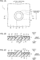
FIG. 1 is a perspective view of a substrate support structure according to an embodiment of the present invention, in exemplary use; -
FIG. 2A is an enlarged view of part II ofFIG. 1 and illustrates part II viewed in the height direction; -
FIG. 2B is a sectional view taken along line IIB-IIB ofFIG. 2A ; -
FIG. 2C corresponds toFIG. 2B and illustrates a protrusion before caulking; -
FIG. 3A corresponds toFIG. 2A and illustrates a substrate support structure according to a first modification; -
FIG. 3B is a sectional view taken along line IIIB-IIIB ofFIG. 3A ; -
FIG. 4A corresponds toFIG. 2A and illustrates a substrate support structure according to a second modification; -
FIG. 4B is a sectional view taken along line IVB-IVB ofFIG. 4A ; -
FIG. 5A corresponds toFIG. 2B and illustrates a substrate support structure according to a third modification; -
FIG. 5B corresponds toFIG. 2B and illustrates a substrate support structure according to fourth modification; and -
FIGS. 6A and 6B each illustrate a substrate support structure according to a comparative example. - Various embodiments will be described hereinafter with reference to the accompanying drawings.
- As illustrated in
FIG. 1 , asubstrate support structure 1 according to an embodiment of the present invention is used in order to secure a substrate (electronic control board) 5 that monitors a lithium-ion battery 3 mounted on, for example, an electric vehicle (EV), to asubstrate support 7. Thesubstrate support structure 1 includes thesubstrate support 7 and thesubstrate 5. Thesubstrate 5 is provided withelectronic components 9 and a wiring pattern not illustrated. - For convenience of description, a predetermined direction is defined as the longitudinal direction. Another predetermined direction orthogonal to the longitudinal direction is defined as the lateral direction. A direction orthogonal to the longitudinal direction and the lateral direction is defined as the height direction. Note that the height direction is not necessarily identical to the up-and-down direction.
- As illustrated in
FIGS. 2A and 2B , thesubstrate support 7 includes asupport body 11 and a protrusion (boss portion) 13. Theprotrusion 13 includes abase portion 15 and a leading-end portion 17, and protrudes upward in the height direction from thesupport body 11. The leading-end portion 17 is larger in outer diameter than thebase portion 15. For example, thesubstrate support 7 is integrally molded out of thermoplastic resin. - The
substrate 5 includes asubstrate body 19. Thesubstrate body 19 is provided with athrough hole 21 and a protruded portion (wall portion or surrounding wall portion) 23. Theprotruded portion 23 surrounds the throughhole 21 and slightly protrudes upward in the height direction from a first face (upper face) 25 that is one face in the thickness direction of thesubstrate body 19. - In the
substrate support structure 1, thebase portion 15 of theprotrusion 13 passes in the height direction through thethrough hole 21. Inside theprotruded portion 23, the leading-end portion 17 of theprotrusion 13 slightly protrudes upward in the height direction from the first face (upper face) 25 of thesubstrate body 19. The leading-end portion 17 of theprotrusion 13 covers the outer edge of the throughhole 21 and engages with thesubstrate body 19. - In addition, the
support body 11 is, for example, tabular in shape. Theprotrusion 13 protrudes from a first face (upper face) 27 that is one face in the thickness direction of thesupport body 11 tabular in shape. Thebase portion 15 of theprotrusion 13 is, for example, pillar-shaped, such as columnar in shape. The height direction of thebase portion 15 is identical to the thickness direction of thesupport body 11, and the directions thereof are identical to the height direction. - The leading-
end portion 17 of theprotrusion 13 is, for example, spherical-cap-shaped. A spherical cap is the solid smaller in volume in two solids resulting from a sphere divided into two by a plane not passing through the center of the sphere. The leading-end portion 17, which is spherical-cap shaped, is identical in height direction to thebase portion 15. - Note that the leading-
end portion 17 is not perfectly spherical-cap-shaped, but is substantially spherical-cap-shaped. For example, the leading-end portion 17 has a shape in which a low column is joined to the plane (bottom face) of a spherical cap. In any case, the lower face of the leading-end portion 17 is planar. That is the leading-end portion 17 has aplanar portion 29. - In the
protrusion 13, a leading-end face (upper face farthest from the support body) 31 in the height direction of thebase portion 15 and theplanar portion 29 of the leading-end portion are joined together. Note that the outer diameter of the leading-end portion 17, which is spherical-cap shaped, is larger in value than the outer diameter of thebase portion 15, which is columnar in shape. The leading-end portion 17, which is spherical-cap shaped, is identical in central axis to thebase portion 15, which is columnar in shape. - The
substrate body 19 is, for example, tabular in shape. The throughhole 21 of thesubstrate body 19 is, for example, pillar-shaped, such as columnar in shape, and passes through thesubstrate body 19 in the thickness direction thereof. - The protruded
portion 23 is filmy in shape and covers, on thesubstrate body 19, the first face (upper face) 25 in the thickness direction of thesubstrate body 19. Thesubstrate body 19 is identical in thickness direction to the protrudedportion 23. The directions thereof are identical to the height direction. Note that anon-protruded region 33 provided with no protrudedportion 23 is provided at part of thefirst face 25 in the thickness direction of thesubstrate body 19. When viewed in the thickness direction of the protrudedportion 23 and the substrate body 19 (height direction), thenon-protruded region 33 has a predetermined shape, such as a circle. - When viewed in the thickness direction of the protruded
portion 23 and thesubstrate body 19, the center of thenon-protruded region 33 is identical in position to the center of the throughhole 21. The diameter (inner diameter) of thenon-protruded region 33 is larger in value than the diameter (inner diameter) of the throughhole 21. - In such an aspect in which the protruded
portion 23 is filmy in shape as described above, the protrudedportion 23 may be referred to as "filmy portion". However, because of thenon-protruded region 33, the protrudedportion 23 can be regarded as protruding upward from thesubstrate body 19. Thus, the protrudedportion 23 may be allowed to be referred to as "protruded portion". - In the
substrate support structure 1, a second face (lower face) 35 that is the other face in the thickness direction of thesubstrate body 19 is in face contact with the first face (upper face) 27 of thesupport body 11, and thesupport body 11 is identical in thickness direction to thesubstrate body 19. - In the
substrate support structure 1, theplanar portion 29 circularly annular in shape of the leading-end portion 17 of theprotrusion 13 is in face contact with thefirst face 25 of thesubstrate body 19. More specifically, theplanar portion 29 of the leading-end portion 17 is in face contact with thesubstrate body 19 exposed in thenon-protruded region 33. Thus, in the thickness direction of thesupport body 11 and the substrate body 19 (height direction), thesubstrate 5 is interposed between thesupport body 11 and the leading-end portion 17 of theprotrusion 13. Note that, in the interposition, for example, thesubstrate 5 is given urging force. - In the
substrate support structure 1, the central axis of the throughhole 21, the central axis of theprotrusion 13, and the center of thenon-protruded region 33 are identical to each other. The diameter (inner diameter) of the throughhole 21 is larger in value than the diameter (outer diameter) of thebase portion 15 of theprotrusion 13 and is smaller in value than the diameter (outer diameter) of the leading-end portion 17 of theprotrusion 13. Furthermore, the outer diameter of the leading-end portion 17 of theprotrusion 13 is identical in value to the inner diameter of thenon-protruded region 33, and thus the leading-end portion 17 fits in thenon-protruded region 33. Furthermore, the entire of the outer circumference of the leading-end portion 17 of theprotrusion 13 is in contact with the entire of the inner circumference of thenon-protruded region 33. - In the
substrate support structure 1, the leading-end portion 17 of theprotrusion 13 slightly protrudes upward above the protrudedportion 23 in the height direction of thesubstrate body 19. However, the leading-end portion 17 may be flush with the protrudedportion 23 or the leading-end portion 17 may be recessed downward below the protrudedportion 23. - The
substrate 5 is thinly tabular in shape, having flexibility. For example, thesubstrate 5 is achieved with a printed wiring board, such as a flexible printed circuit (FPC) board. In thesubstrate support structure 1, as described above, thesecond face 35 of thesubstrate body 19 is in contact with thefirst face 27 of thesupport body 11 from which theprotrusion 13 of thesupport body 11 protrudes. - In the
substrate support structure 1, the protrudedportion 23 is achieved with a resist (resist film) 43 provided on thesubstrate body 19 or a coverlay provided on thesubstrate body 19. - Next, a method of forming the
substrate support structure 1 will be described. - First, as illustrated in
FIG. 2C , thesubstrate 5 is temporarily fixed to thesubstrate support 7. In the temporary fixing, theprotrusion 13 is columnar in shape and passes in the height direction through the throughhole 21 of thesubstrate body 19. Thesecond face 35 of thesubstrate body 19 is in contact with thefirst face 27 of thesupport body 11. - Next, the leading end of the
protrusion 13 is softened, for example, by melting and then is hardened, so that the leading-end portion 17 is formed due to the deformation (refer toFIG. 2B ). That is the leading end of theprotrusion 13 is caulked by heat, resulting in formation of the leading-end portion 17. Thus, thesubstrate 5 is integrally fixed to thesubstrate support 7. - According to the
substrate support structure 1, thesubstrate body 19 is provided with the protrudedportion 23 surrounding the leading-end portion 17 of theprotrusion 13 of thesubstrate support 7. Thus, even when the leading end of theprotrusion 13 is melted at the time of formation of the leading-end portion 17 of theprotrusion 13, the melted leading end is dammed by the protrudedportion 23. - Thus, the leading end of the
protrusion 13 softened due to melting can be prevented from spreading unnecessarily on thefirst face 25 of thesubstrate 5, so that, for example, the wiring pattern and theelectronic components 9 provided on thesubstrate 5 can be protected against adverse influence. - In contrast to this, in a
substrate support structure 301 according to a comparative example illustrated inFIG. 6A , asubstrate 305 is fixed to asubstrate support 307 with a screw (bolt) 303. Therefore, in a case where thesubstrate 305 is, for example, a flexible printed circuit (FPC) board, having flexibility, rotation of thescrew 303 is likely to cause thesubstrate 305 to be entangled with thescrew 303, resulting in deformation or damage. - In a
substrate support structure 351 according to another comparative example illustrated inFIG. 6B , the leading end of aprotrusion 355 provided at asubstrate support 353 is caulked by application of heat, so that asubstrate 357 is fixed to thesubstrate support 353. - The
substrate support structure 351 according to the another comparative example does not have such a protruded portion as the protrudedportion 23 in thesubstrate support structure 1 according to the embodiment of the present invention. Thus, the leading end of theprotrusion 355 melted due to heat spreads unnecessarily on the surface of thesubstrate 357. - In the
substrate support structure 1, theprotrusion 13 of thesupport body 11 is caulked by heat, so that thesubstrate 5 is fixed to thesubstrate support 7. Therefore, at the time of fixing of thesubstrate 5 to thesubstrate support 7, almost no external force is applied to thesubstrate 5. Thus, even in a case where thesubstrate 5 is, for example, a flexible printed circuit board, being thinly tabular in shape and having flexibility, no damage is likely to occur. - In the
substrate support structure 1, because thesecond face 35 of thesubstrate body 19 is in contact with thefirst face 27 of thesupport body 11, thesubstrate 5, which is flexible and is fixed to thesubstrate support 7, can be inhibited from deforming, as much as possible. - In the
substrate support structure 1, the protrudedportion 23 is achieved with the resist or the coverlay. Thus, there is no need to provide a process of forming the protruded portion, so that the manufacturing process can be simplified. - In the
substrate support structure 1, arecess 37 may be provided as indicated with a chain double-dashed line inFIG. 2B . The recess is provided at the center of the leading-end portion 17 and is recessed downward from the upper face of the leading-end portion 17. Provision of therecess 37 enables saving of material necessary for formation of the leading-end portion 17. - Note that, in the
substrate support structure 1, as illustrated inFIGS. 3A and 3B , the protrudedportion 23 may be achieved withpart 39 of the wiring pattern provided on thefirst face 25 of thesubstrate body 19. This arrangement enables simplification of the manufacturing process without a process of forming the protrudedportion 23. - The
part 39 of the wiring pattern as the protrudedportion 23 is, for example, annular in shape, such as circularly annular in shape, and slightly protrudes upward from thefirst face 25 of thesubstrate body 19. Achievement of the protrudedportion 23 with such a wiring pattern leads to an aspect in which the protrudedportion 23 protruding upward from the upper face of thesubstrate body 19 serves as a "protruded portion". - The part of the wiring pattern as the protruded
portion 23 is not in connection with the other part of the wiring pattern that functions as a conductor for an electronic circuit. However, the part of the wiring pattern as the protrudedportion 23 may be in connection with the other part of the wiring pattern that functions as a conductor for an electronic circuit. - In the
substrate support structure 1, as illustrated inFIGS. 3A and 3B , the protrudedportion 23 may be formed with thepart 39 of the wiring pattern andsolder 41. As described above, thepart 39 of the wiring pattern is annular in shape, such as circularly annular in shape. Similarly, thesolder 41 is annular in shape, such as circularly annular in shape. Thepart 39 of the wiring pattern is provided on thesubstrate body 19, and thesolder 41 is provided on thepart 39 of the wiring pattern. Because thesolder 41 is provided such that thesolder 41 overlaps thepart 39 of the wiring pattern, the protrudedportion 23 has an increase in the value of height. Note that afilmy object 43 illustrated inFIG. 3B is a resist. - Note that, in the aspect illustrated in
FIG. 3B , thepart 39 of the wiring pattern may be eliminated and the protrudedportion 23 may be formed with thesolder 41. - In the
substrate support structure 1, as illustrated inFIGS. 4A and 4B , the protrudedportion 23 may be formed with a ring-shaped member (e.g., a washer) 45 having a predetermined thickness. For example, through a glue or an adhesive such as a two-sided adhesive tape, thewasher 45 is secured on the resist 43, which is filmy in shape, provided on thesubstrate body 19. Detachably provision of thewasher 45 on thesubstrate 5 through an adhesive or the like enables easy removal of thewasher 45 from thesubstrate 5 after formation of the leading-end portion 17 of theprotrusion 13. - Achievement of the protruded
portion 23 with thepart 39 of the wiring pattern and thesolder 41 or thewasher 45 enables an easy increase in the value of protruded height (thickness) of the protrudedportion 23. Then, the leading end of theprotrusion 13 softened due to melting can be more reliably prevented from spreading unnecessarily on the surface of thesubstrate 5. - Note that, in the
substrate support structure 1, the protrudedportion 23 may be formed by any appropriate combination of the methods described withFIGS. 2A to 4B . That is the protrudedportion 23 may be achieved with at least any of thesolder 41 provided to thesubstrate body 19, thepart 39 of the wiring pattern provided to the substrate body, and thewasher 45 provided to thesubstrate body 19. - Note that, for the
substrate support structure 1, either of the respective configurations illustrated inFIGS. 5A and 5B may be adopted. - In
FIG. 5A , theprotrusion 13 has an intermediate portion provided with astep portion 47. Thesubstrate 5 abuts on thestep portion 47 such that thesubstrate 5 is spaced apart from thesupport body 11 in the height direction. Thus, aspace 49 is interposed between thesubstrate 5 and thesupport body 11. - In
FIG. 5B , thestep portion 47 is formed with aspacer 51 that is separate from theprotrusion 13 and is tubular in shape, such as cylindrical in shape. - An aspect of usage of the
substrate support structure 1 will be described now with reference toFIG. 1 . Note that, for convenience of description, the height direction, the longitudinal direction, and the lateral direction are defined inFIG. 1 . However, in an aspect of practical usage, the longitudinal direction is identical to the up-and-down direction (height direction). The description will be given with the directions along the aspect of practical usage. - The substrate (e.g., a flexible printed circuit (FPC) board) 5 is provided with a cell-voltage detection circuit unit (not illustrated) arranged on the upper side of a
battery module 53 and the detection lines thereof, integrally. Thesubstrate 5 is bent such that thesubstrate 5 is fixed along an end plate 55 (substrate support 7) of thebattery module 53. Oneportion 57 segmented by the bent of thesubstrate 5 is fixed to theend plate 55 due to thesubstrate support structure 1. - The one
portion 57 of thesubstrate 5 is equipped withtall components 59 among the circuit components. Thus, thebattery module 53 can have a reduction in the value of height as a whole. - Note that the above description may be grasped as a method of forming the substrate support structure, the method including a substrate temporary fixing process and a protruding leading-end forming process (substrate fixing process). The substrate temporary fixing process is a process of temporarily fixing the
substrate 5 to thesubstrate support 7. The protruding leading-end forming process is a process of thermally caulking the leading end of theprotrusion 13 to form the leading-end portion 17. - While certain embodiments have been described, these embodiments have been presented by way of example only, and are not intended to limit the scope of the inventions. Indeed, the novel embodiments described herein may be embodied in a variety of other forms; furthermore, various omissions, substitutions and changes in the form of the embodiments described herein may be made without departing from the spirit of the inventions. The accompanying claims and their equivalents are intended to cover such forms or modifications as would fall within the scope and spirit of the inventions.
Claims (5)
- A substrate support structure comprising:a substrate support including: a support body; and a protrusion including a base portion and a leading-end portion larger in outer diameter than the base portion, the protrusion protruding from the support body; anda substrate having: a substrate body; a through hole provided at the substrate body; and a protruded portion surrounding the through hole, the protruded portion protruding from a first face that is one face in a thickness direction of the substrate body, whereinthe base portion of the protrusion passes through the through hole, andthe leading-end portion of the protrusion protrudes from the first face of the substrate body inside the protruded portion and engages with the substrate body such that the through hole is covered.
- The substrate support structure according to claim 1, wherein the substrate is thinly tabular in shape and has flexibility.
- The substrate support structure according to claim 2, wherein a second face that is another face in the thickness direction of the substrate body is in contact with a face of the support body from which the protrusion protrudes.
- The substrate support structure according to any one of claims 1 to 3, wherein the protruded portion is formed of at least any of a resist provided to the substrate body, a coverlay provided to the substrate body, solder provided to the substrate body, part of a wiring pattern provided to the substrate body, and a washer provided to the substrate body.
- A method of forming a substrate support structure, the method comprising:a substrate temporary fixing process of temporarily fixing a substrate having a substrate body, a through hole provided at the substrate body, and a protruded portion surrounding the through hole and protruding from a first face that is one face in a thickness direction of the substrate body, to a substrate support including a support body and a protrusion protruding from the support body such that a second face that is another face in the thickness direction of the substrate body faces the substrate support and the protrusion passes through the through hole; anda protruding leading-end forming process of deforming, by softening and then by hardening, a leading end of the protrusion protruding from the through hole due to the substrate temporary fixing process such that the leading end of the protrusion covers the through hole and fits inside the protruded portion, to fix the substrate to the substrate support.
Applications Claiming Priority (1)
| Application Number | Priority Date | Filing Date | Title |
|---|---|---|---|
| JP2020085807A JP7248620B2 (en) | 2020-05-15 | 2020-05-15 | SUBSTRATE SUPPORT STRUCTURE AND METHOD OF FORMING SUBSTRATE SUPPORT STRUCTURE |
Publications (1)
| Publication Number | Publication Date |
|---|---|
| EP3911136A1 true EP3911136A1 (en) | 2021-11-17 |
Family
ID=75914242
Family Applications (1)
| Application Number | Title | Priority Date | Filing Date |
|---|---|---|---|
| EP21173295.3A Pending EP3911136A1 (en) | 2020-05-15 | 2021-05-11 | Substrate support structure and method of forming the same |
Country Status (4)
| Country | Link |
|---|---|
| US (1) | US11483924B2 (en) |
| EP (1) | EP3911136A1 (en) |
| JP (1) | JP7248620B2 (en) |
| CN (1) | CN113677117A (en) |
Citations (5)
| Publication number | Priority date | Publication date | Assignee | Title |
|---|---|---|---|---|
| JP2010208173A (en) * | 2009-03-11 | 2010-09-24 | Toyoda Gosei Co Ltd | Heat calking structure |
| JP2011254001A (en) * | 2010-06-03 | 2011-12-15 | Denso Corp | Circuit board and its assembling method |
| US20120160543A1 (en) * | 2010-12-23 | 2012-06-28 | Denso Corporation | Circuit board to be attached to support through thermoplastic staking |
| JP6332118B2 (en) * | 2015-04-10 | 2018-05-30 | 株式会社デンソー | Electronic equipment |
| JP2018137317A (en) | 2017-02-21 | 2018-08-30 | 株式会社デンソー | Electronic device |
Family Cites Families (10)
| Publication number | Priority date | Publication date | Assignee | Title |
|---|---|---|---|---|
| JPS5064878U (en) * | 1973-10-15 | 1975-06-12 | ||
| JPS61112990A (en) * | 1984-11-06 | 1986-05-30 | Seiko Epson Corp | Electronic circuit unit for electronic wristwatches |
| JPH0643311U (en) * | 1992-11-18 | 1994-06-07 | 矢崎総業株式会社 | Welding structure between resin protrusion and mounting plate |
| JPH09321463A (en) * | 1996-05-24 | 1997-12-12 | Kokusai Electric Co Ltd | Electronic device housing structure |
| JP2000245034A (en) * | 1999-02-24 | 2000-09-08 | Sumitomo Wiring Syst Ltd | Assembly of wiring board |
| TW200306770A (en) * | 2002-02-22 | 2003-11-16 | Fujikura Ltd | Multilayer wiring board, base for multilayer wiring board, printed wiring board, and its manufacturing method |
| JP2008168437A (en) | 2007-01-09 | 2008-07-24 | Aisin Seiki Co Ltd | Heat welding equipment |
| US10099423B2 (en) | 2015-02-28 | 2018-10-16 | GM Global Technology Operations LLC | Methods for joining components by heat staking |
| JP6420743B2 (en) * | 2015-11-02 | 2018-11-07 | タイコエレクトロニクスジャパン合同会社 | Fixed structure |
| SE541042C2 (en) * | 2016-11-16 | 2019-03-19 | Scania Cv Ab | A welding arrangement and a vehicle comprising such a welding arrangement |
-
2020
- 2020-05-15 JP JP2020085807A patent/JP7248620B2/en active Active
-
2021
- 2021-05-11 EP EP21173295.3A patent/EP3911136A1/en active Pending
- 2021-05-12 US US17/318,111 patent/US11483924B2/en active Active
- 2021-05-14 CN CN202110528782.6A patent/CN113677117A/en active Pending
Patent Citations (5)
| Publication number | Priority date | Publication date | Assignee | Title |
|---|---|---|---|---|
| JP2010208173A (en) * | 2009-03-11 | 2010-09-24 | Toyoda Gosei Co Ltd | Heat calking structure |
| JP2011254001A (en) * | 2010-06-03 | 2011-12-15 | Denso Corp | Circuit board and its assembling method |
| US20120160543A1 (en) * | 2010-12-23 | 2012-06-28 | Denso Corporation | Circuit board to be attached to support through thermoplastic staking |
| JP6332118B2 (en) * | 2015-04-10 | 2018-05-30 | 株式会社デンソー | Electronic equipment |
| JP2018137317A (en) | 2017-02-21 | 2018-08-30 | 株式会社デンソー | Electronic device |
Also Published As
| Publication number | Publication date |
|---|---|
| JP2021180282A (en) | 2021-11-18 |
| US20210360769A1 (en) | 2021-11-18 |
| US11483924B2 (en) | 2022-10-25 |
| CN113677117A (en) | 2021-11-19 |
| JP7248620B2 (en) | 2023-03-29 |
Similar Documents
| Publication | Publication Date | Title |
|---|---|---|
| US8243454B2 (en) | Electronic control unit | |
| EP3467945B1 (en) | Flexible flat cable connection tool, flexible flat cable connection structure, and rotary connector device | |
| JP5878101B2 (en) | Electronic control unit | |
| JP6168362B2 (en) | Circuit structure, electrical junction box and spacer | |
| JP2014063868A (en) | Electronic controller | |
| US7529104B2 (en) | Conduction device | |
| WO2019194153A1 (en) | Capacitor, manufacturing method of capacitor, and pedestal for capacitor | |
| US7537459B2 (en) | Anisotropic conductive film | |
| US11483924B2 (en) | Substrate support structure and method of forming the same | |
| CN113097760A (en) | Connector assembling structure | |
| JP6332118B2 (en) | Electronic equipment | |
| US7592960B2 (en) | High frequency capacitive coupling antenna for vehicles | |
| JP4233465B2 (en) | Electronic component mounting structure on flexible board | |
| CN208112751U (en) | Camera modules and electronics | |
| JP5239926B2 (en) | Electronic device and manufacturing method thereof | |
| JP7478732B2 (en) | Flexible printed wiring board and battery wiring module | |
| JP2019164953A (en) | Rotation connector | |
| CN220553605U (en) | Wireless power supply assembly of laser radar and laser radar | |
| JP2009164266A (en) | Manufacturing method of electronic apparatus, and electronic apparatus | |
| CN219875208U (en) | Wireless charging device and car | |
| JP6805540B2 (en) | Manufacturing method of leaf spring fixed structure and electrical contact structure | |
| CN213781898U (en) | Operation switch structure | |
| JP2025119814A (en) | Electronic unit and method for manufacturing the electronic unit | |
| JP2000252606A (en) | Electronic component and structure for mounting electronic component | |
| CN119518308A (en) | Wireless power supply component of laser radar, manufacturing method and laser radar |
Legal Events
| Date | Code | Title | Description |
|---|---|---|---|
| PUAI | Public reference made under article 153(3) epc to a published international application that has entered the european phase |
Free format text: ORIGINAL CODE: 0009012 |
|
| STAA | Information on the status of an ep patent application or granted ep patent |
Free format text: STATUS: REQUEST FOR EXAMINATION WAS MADE |
|
| 17P | Request for examination filed |
Effective date: 20210511 |
|
| AK | Designated contracting states |
Kind code of ref document: A1 Designated state(s): AL AT BE BG CH CY CZ DE DK EE ES FI FR GB GR HR HU IE IS IT LI LT LU LV MC MK MT NL NO PL PT RO RS SE SI SK SM TR |
|
| B565 | Issuance of search results under rule 164(2) epc |
Effective date: 20211012 |
|
| STAA | Information on the status of an ep patent application or granted ep patent |
Free format text: STATUS: EXAMINATION IS IN PROGRESS |
|
| 17Q | First examination report despatched |
Effective date: 20230504 |
|
| RAP3 | Party data changed (applicant data changed or rights of an application transferred) |
Owner name: YAZAKI CORPORATION |