EP3910930B1 - Camera device - Google Patents
Camera device Download PDFInfo
- Publication number
- EP3910930B1 EP3910930B1 EP20738820.8A EP20738820A EP3910930B1 EP 3910930 B1 EP3910930 B1 EP 3910930B1 EP 20738820 A EP20738820 A EP 20738820A EP 3910930 B1 EP3910930 B1 EP 3910930B1
- Authority
- EP
- European Patent Office
- Prior art keywords
- angle adjustment
- sidewall
- view angle
- bracket
- adjustment member
- Prior art date
- Legal status (The legal status is an assumption and is not a legal conclusion. Google has not performed a legal analysis and makes no representation as to the accuracy of the status listed.)
- Active
Links
Images


Classifications
-
- F—MECHANICAL ENGINEERING; LIGHTING; HEATING; WEAPONS; BLASTING
- F16—ENGINEERING ELEMENTS AND UNITS; GENERAL MEASURES FOR PRODUCING AND MAINTAINING EFFECTIVE FUNCTIONING OF MACHINES OR INSTALLATIONS; THERMAL INSULATION IN GENERAL
- F16M—FRAMES, CASINGS OR BEDS OF ENGINES, MACHINES OR APPARATUS, NOT SPECIFIC TO ENGINES, MACHINES OR APPARATUS PROVIDED FOR ELSEWHERE; STANDS; SUPPORTS
- F16M11/00—Stands or trestles as supports for apparatus or articles placed thereon ; Stands for scientific apparatus such as gravitational force meters
- F16M11/02—Heads
- F16M11/04—Means for attachment of apparatus; Means allowing adjustment of the apparatus relatively to the stand
- F16M11/06—Means for attachment of apparatus; Means allowing adjustment of the apparatus relatively to the stand allowing pivoting
- F16M11/10—Means for attachment of apparatus; Means allowing adjustment of the apparatus relatively to the stand allowing pivoting around a horizontal axis
-
- B—PERFORMING OPERATIONS; TRANSPORTING
- B60—VEHICLES IN GENERAL
- B60R—VEHICLES, VEHICLE FITTINGS, OR VEHICLE PARTS, NOT OTHERWISE PROVIDED FOR
- B60R11/00—Arrangements for holding or mounting articles, not otherwise provided for
- B60R11/04—Mounting of cameras operative during drive; Arrangement of controls thereof relative to the vehicle
-
- F—MECHANICAL ENGINEERING; LIGHTING; HEATING; WEAPONS; BLASTING
- F16—ENGINEERING ELEMENTS AND UNITS; GENERAL MEASURES FOR PRODUCING AND MAINTAINING EFFECTIVE FUNCTIONING OF MACHINES OR INSTALLATIONS; THERMAL INSULATION IN GENERAL
- F16M—FRAMES, CASINGS OR BEDS OF ENGINES, MACHINES OR APPARATUS, NOT SPECIFIC TO ENGINES, MACHINES OR APPARATUS PROVIDED FOR ELSEWHERE; STANDS; SUPPORTS
- F16M11/00—Stands or trestles as supports for apparatus or articles placed thereon ; Stands for scientific apparatus such as gravitational force meters
- F16M11/02—Heads
- F16M11/18—Heads with mechanism for moving the apparatus relatively to the stand
-
- F—MECHANICAL ENGINEERING; LIGHTING; HEATING; WEAPONS; BLASTING
- F16—ENGINEERING ELEMENTS AND UNITS; GENERAL MEASURES FOR PRODUCING AND MAINTAINING EFFECTIVE FUNCTIONING OF MACHINES OR INSTALLATIONS; THERMAL INSULATION IN GENERAL
- F16M—FRAMES, CASINGS OR BEDS OF ENGINES, MACHINES OR APPARATUS, NOT SPECIFIC TO ENGINES, MACHINES OR APPARATUS PROVIDED FOR ELSEWHERE; STANDS; SUPPORTS
- F16M13/00—Other supports for positioning apparatus or articles; Means for steadying hand-held apparatus or articles
- F16M13/02—Other supports for positioning apparatus or articles; Means for steadying hand-held apparatus or articles for supporting on, or attaching to, an object, e.g. tree, gate, window-frame, cycle
-
- G—PHYSICS
- G03—PHOTOGRAPHY; CINEMATOGRAPHY; ANALOGOUS TECHNIQUES USING WAVES OTHER THAN OPTICAL WAVES; ELECTROGRAPHY; HOLOGRAPHY
- G03B—APPARATUS OR ARRANGEMENTS FOR TAKING PHOTOGRAPHS OR FOR PROJECTING OR VIEWING THEM; APPARATUS OR ARRANGEMENTS EMPLOYING ANALOGOUS TECHNIQUES USING WAVES OTHER THAN OPTICAL WAVES; ACCESSORIES THEREFOR
- G03B17/00—Details of cameras or camera bodies; Accessories therefor
- G03B17/56—Accessories
- G03B17/561—Support related camera accessories
-
- H—ELECTRICITY
- H04—ELECTRIC COMMUNICATION TECHNIQUE
- H04N—PICTORIAL COMMUNICATION, e.g. TELEVISION
- H04N23/00—Cameras or camera modules comprising electronic image sensors; Control thereof
- H04N23/50—Constructional details
- H04N23/51—Housings
-
- H—ELECTRICITY
- H04—ELECTRIC COMMUNICATION TECHNIQUE
- H04N—PICTORIAL COMMUNICATION, e.g. TELEVISION
- H04N23/00—Cameras or camera modules comprising electronic image sensors; Control thereof
- H04N23/57—Mechanical or electrical details of cameras or camera modules specially adapted for being embedded in other devices
-
- H—ELECTRICITY
- H04—ELECTRIC COMMUNICATION TECHNIQUE
- H04N—PICTORIAL COMMUNICATION, e.g. TELEVISION
- H04N23/00—Cameras or camera modules comprising electronic image sensors; Control thereof
- H04N23/60—Control of cameras or camera modules
- H04N23/695—Control of camera direction for changing a field of view, e.g. pan, tilt or based on tracking of objects
-
- B—PERFORMING OPERATIONS; TRANSPORTING
- B60—VEHICLES IN GENERAL
- B60R—VEHICLES, VEHICLE FITTINGS, OR VEHICLE PARTS, NOT OTHERWISE PROVIDED FOR
- B60R11/00—Arrangements for holding or mounting articles, not otherwise provided for
- B60R2011/0042—Arrangements for holding or mounting articles, not otherwise provided for characterised by mounting means
- B60R2011/008—Adjustable or movable supports
- B60R2011/0085—Adjustable or movable supports with adjustment by rotation in their operational position
-
- G—PHYSICS
- G03—PHOTOGRAPHY; CINEMATOGRAPHY; ANALOGOUS TECHNIQUES USING WAVES OTHER THAN OPTICAL WAVES; ELECTROGRAPHY; HOLOGRAPHY
- G03B—APPARATUS OR ARRANGEMENTS FOR TAKING PHOTOGRAPHS OR FOR PROJECTING OR VIEWING THEM; APPARATUS OR ARRANGEMENTS EMPLOYING ANALOGOUS TECHNIQUES USING WAVES OTHER THAN OPTICAL WAVES; ACCESSORIES THEREFOR
- G03B30/00—Camera modules comprising integrated lens units and imaging units, specially adapted for being embedded in other devices, e.g. mobile phones or vehicles
Definitions
- the present embodiment relates to a camera device.
- JP H11 78716 A discloses a camera device as defined in the preamble of claim 1.
- KR 2013 0015743 A discloses a vehicle camera, wehich parallelly gazes the forward area steadily at the downward slope phase in case discloses the driving with the downstream slope road surface.
- micro-camera modules have been developed, and micro-camera modules are widely used in small electronic products such as smart phones, notebook computers, and game consoles.
- a black box camera for the protection of a vehicle or objective data of a traffic accident a rear surveillance camera that enables the driver to monitor the blind spot at the rear of the vehicle through the screen to ensure safety when the vehicle is reversing, a surrounding detection camera that can monitor the surroundings of the vehicle, and the like are provided.
- LKAS lane keeping assist system
- the problem to be solved by the present invention is to provide a camera device capable of reducing costs.
- the invention is as defined in claim 1.
- first sidewall includes a first opening in which a portion of the view angle adjustment member is disposed
- second sidewall may include a second opening exposing an end of the first portion of the view angle adjustment member to the outside.
- first region of the elastic member may include a third opening corresponding to the first opening
- second region of the elastic member may include a fourth opening corresponding to the second opening
- the camera module includes a coupling portion to which the second portion of the view angle adjustment member is coupled so that the position of the camera module is adjusted; the coupling portion of the camera module and the support portion of the bracket are spaced apart; and when the distance between the coupling portion and the support portion is increased, a distance between the upper portion of the camera module and the upper portion of the bracket may be greater than the distance between the lower portion of the camera module and the lower portion of the bracket.
- the first opening may be formed to have a length in a first direction longer than a length in a second direction perpendicular to the first direction.
- the elastic member may be formed in a 'U' shape.
- one surface of the locking portion of the view angle adjustment member may be formed in a curved shape.
- first sidewall of the support portion may include a first groove having a curved shape corresponding to a curved shape of one surface of the locking portion.
- the other side of the view angle adjustment member may be screw-coupled to the coupling portion.
- a length at which the view angle adjustment member and the camera module are screw-coupled, and a rotation angle of the camera module with respect to the bracket may correspond to each other.
- the end of the view angle adjustment member may be disposed between the first opening and the second opening.
- first region of the elastic member is in contact with one side of the locking portion of the view angle adjustment member to elastically support the view angle adjustment member, and the second region of the elastic member may be supported by one surface of the second sidewall of the support portion of the bracket.
- the first region of the elastic member may be in line contact with the one side of the locking portion of the view angle adjustment member to fix the view angle adjustment member in a predetermined position with respect to the bracket.
- the second sidewall of the support portion of the bracket includes a protrusion formed by being extended from the inner side surface to the other side, and the second region of the elastic member may be disposed between the protrusion of the bracket and a bottom surface of the support portion.
- the coupling portion of the camera module may include a second groove.
- it may include a loosening prevention portion disposed in the second groove and penetrated by the body of the view angle adjustment member.
- the camera module may include a housing and extension portions being extended from both ends of the housing, and the extension portion may be hingedly coupled to the bracket.
- a camera device capable of reducing costs can be provided through the present embodiment.
- the singular form may include the plural form unless specifically stated in the phrase, and when described as "at least one (or more than one) of A and B and C", it may include one or more of all combinations that can be combined with A, B, and C.
- first, second, A, B, (a), and (b) may be used. These terms are merely intended to distinguish the components from other components, and the terms do not limit the nature, order or sequence of the components.
- a component when a component is described as being 'connected', 'coupled' or 'interconnected' to another component, the component is not only directly connected, coupled or interconnected to the other component, but may also include cases of being 'connected', 'coupled', or 'interconnected' due that another component between that other components.
- FIG. 1 is a schematic diagram of a vehicle equipped with a camera angle adjustment device according to an embodiment of the present invention.
- the camera device may include a camera angle adjustment device 10 .
- the camera angle adjustment device 10 may be coupled to a wind shield 2 of a vehicle 1.
- the wind shield 2 may be disposed in the front or rear of the vehicle 1.
- the wind shield 2 is formed of a transparent material so that the driver can look forward or rearward.
- the wind shield 2 may include a front wind shield disposed in front of the vehicle 1 and a rear wind shield disposed in the rear of the vehicle.
- the camera angle adjustment device 10 may be coupled to the inner side surface of the wind shield 2.
- the camera angle adjustment device 10 is described as an example that is coupled to the front wind shield, but may be coupled to the rear wind shield.
- the bracket 100 of the camera angle adjustment device 10 may be directly coupled to the inner side surface of the wind shield 2 by a method such as adhesion, or the camera angle adjustment device 10 may be coupled to the wind shield 2 through a separate coupler (not shown) and/or a cover (not shown).
- FIGS. 2 and 3 are perspective views of a camera angle adjustment device according to an embodiment of the present invention.
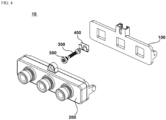
- FIG. 4 is an exploded perspective view of a camera angle adjustment device according to an embodiment of the present invention.
- FIG. 5 is an enlarged view of part A of FIG. 3 .
- FIGS. 6 and 7 are perspective views of a view angle adjustment member, an elastic member, and a loosening prevention portion of the camera angle adjustment device according to an embodiment of the present invention.
- FIG. 8 is a perspective view of a view angle adjusting member and a loosening prevention portion of the camera angle adjusting device according to an embodiment of the present invention.
- FIGS. 9 and 10 are schematic diagrams of some configurations of a camera angle adjustment device according to an embodiment of the present invention.
- the camera angle adjustment device 10 includes a bracket 100, a camera module 200, a view angle adjustment member 300, and an elastic member 400, and a loosening prevention unit 500 are included.
- the camera angle adjustment device 10 may be installed on the wind shield 2 of the vehicle 1.
- the camera angle adjustment device 10 adjusts the view angle of the camera module 200. Through this, the view angle can be adjusted within the range of the view angle desired by the user by compensating for the manufacturing tolerance of the camera module 200 or the mounting tolerance on the vehicle 1.
- the camera angle adjustment device 10 includes a bracket 100.
- the bracket 100 is disposed on one side of the camera module 200.
- the bracket 100 is disposed behind the camera module 200.
- the bracket 100 may be mounted on the wind shield 2 of the vehicle 1.
- the bracket 100 is rotatably support the camera module 200.
- At least a portion of the view angle adjustment member 300 and an elastic member 400 is disposed on the bracket 100.
- the bracket 100 includeS a body 102, an extension portion 104, and a support portion 110.
- the body 102 of the bracket 100 supports the housing 210 of the camera module 200.
- the body 102 is disposed on one side or the rear of the housing 210 of the camera module 200.
- the body 102 is formed in a shape and size corresponding to the housing 210 of the camera module 200.
- Extension portions 104 are formed at both ends of the body 102 of the bracket 100, and a support portion 110 is formed in an upper portion.
- the extension portion 104 of the bracket 100 is extended from both ends of the body 102.
- the extension portion 104 of the bracket 100 is coupled with the extension portion 230 of the camera module 200.
- the extension portion 104 of the bracket 100 is hinged to the extension portion 230 of the camera module 200.
- the extension portion 104 of the bracket 100 may rotatably support the extension portion 230 of the camera module 200.
- the extension portion 104 is described as an example that is formed by being extended from both ends of the body 102 to one side or rear, but is not limited thereto, and formed by being extended forward from both ends of the body 102 or may be formed by being extended in the outer circumferential direction.
- the support portion 110 may be disposed in an upper portion of the body 102.
- the support portion 110 may be formed by being extended upward from the upper surface of the body 102.
- An elastic member 400 may be disposed on the support portion 110.
- One side of the view angle adjustment member 300 may be disposed on the support portion 110.
- the support portion 110 may face the coupling portion 220 of the camera module 200.
- the support portion 110 is spaced apart from the coupling portion 220 of the camera module 200 by a predetermined distance.
- the support portion 110 includes a first sidewall 112, a second sidewall 114, a third sidewall 116, and a fourth sidewall 118.
- One side of the view angle adjustment member 300 includes a first portion.
- One side of the view angle adjustment member 300 includes a first region.
- the other side of the view angle adjustment member 300 includes a second portion.
- the other side of the view angle adjustment member 300 includes a second region.
- the first sidewall 112 is disposed between the camera module 200 and one side of the view angle adjustment member 300.
- the first sidewall 112 may face the coupling portion 220 of the camera module 200.
- the first sidewall 112 faces the second sidewall 114.
- the first sidewall 112 is connected to the third sidewall 116.
- the first sidewall 112 is connected to the fourth sidewall 118 .
- the first sidewall 112 may include a first opening 1122 and a first groove 1124.
- a part of the view angle adjustment member 300 may be disposed in the first opening 1122 of the first sidewall 112.
- the body 310 of the view angle adjustment member 300 is disposed in the first opening 1122 of the first sidewall 112.
- a region without thread 312 among the body 310 of the view angle adjustment member 300 may be disposed.
- the first opening 1122 of the first sidewall 112 may be formed to have a length in a first direction longer than a length in a second direction perpendicular to the first direction.
- the first opening 1122 of the first sidewall 112 may be formed to have a length in a vertical direction longer than a length in the horizontal direction.
- An end portion 320 of the view angle adjustment member 300 may be disposed between the first opening 1122 and the second opening 1142.
- the first groove 1124 of the first sidewall 112 may be formed in a curved shape corresponding to one surface of a locking portion 330 of the view angle adjustment member 300 in the other direction.
- the first groove 1124 of the first sidewall 112 may be formed in a shape symmetrical with respect to the first opening 1122 of the first sidewall 112.
- One surface of the locking portion 330 of the view angle adjustment member 300 may be disposed in the first groove 1124 of the first sidewall 112.
- the size of the first groove 1124 of the first sidewall 112 may be smaller than the size of one surface of the locking portion 330 of the view angle adjustment member 300. Through this, the view angle adjustment member 300 can finely rotate with respect to the first sidewall 112, so that damage to the product can be prevented.
- the second sidewall 114 faces the first sidewall 112.
- the second sidewall 114 is connected to the third sidewall 116 .
- the second sidewall 114 is connected to the fourth sidewall 118.
- the second sidewall 114 may include a second opening 1142 and protrusions 1144 and 1146.
- the end portion 320 and the locking portion 330 of the view angle adjustment member 300 may be disposed.
- the second opening 1142 of the second sidewall 114 may expose an end of one side of the view angle adjustment member 300 to the outside.
- the second opening 1142 of the second sidewall 114 may expose a tool groove 322 of the end portion 320 of the view angle adjustment member 300 to the outside.
- the protrusions 1144 and 1146 of the second sidewall 114 may include two protrusions 1144 and 1146.
- the two protrusions 1144 and 1146 may be formed by being extended from the inner side surface of the second sidewall 114 facing the first sidewall 112 toward the other side of the first sidewall 112.
- the two protrusions 1144 and 1146 of the second sidewall 114 may be formed in a region adjacent to the edge of the first sidewall 112.
- the two protrusions 1144 and 1146 of the second sidewall 114 may be formed in an upper region of the second sidewall 114.
- a second region 420 of the elastic member 400 may be disposed between the two protrusions 1144 and 1146 of the second sidewall 114 and the bottom surface of the support portion 110. Through this, it is possible to prevent the elastic member 400 from being separated.
- the third and fourth sidewalls 116 and 118 connect the first sidewall 112 and the second sidewall 114.
- an end portion 320 of the view angle adjustment member 300, a locking portion 330, and an elastic member 400 may be disposed.
- the length or area of the third sidewall 116 and the fourth sidewall 118 may be formed to be smaller than the length or area of the first and second sidewalls 112 and 114.
- the camera angle adjustment device 10 includes a camera module 200 .
- the camera module 200 may be disposed on the bracket 100.
- the camera module 200 may be disposed on the other side or in front of the bracket 100.
- the camera module 200 is rotatably coupled to the bracket 100.
- the camera module 200 is described by taking a triple camera as an example, but is not limited thereto and may be variously changed, such as a dual camera.
- the camera module 200 may include a housing 210, a coupling portion 220, and an extension portion 230.
- the housing 210 of the camera module 200 may form the outer appearance of the camera module.
- the housing 210 may include at least one hole in which at least one lens module is mounted. Components that can constitute at least one camera may be disposed in the housing 210.
- the housing 210 may be disposed in front of the body 102 of the bracket 100.
- a coupling portion 220 may be formed on an upper portion of the housing 210.
- the other side of the view angle adjustment member 300 may be coupled to the coupling portion 220 of the camera module 200 so that the position of the camera module 200 is adjusted.
- the coupling portion 220 may face the support portion 110 of the bracket 100.
- the coupling portion 220 may be spaced apart from the support portion 110 of the bracket 100 by a predetermined distance. As the distance between the coupling portion 220 and the support portion 110 of the bracket 100 increases, the distance between the upper portion of the camera module 200 and the upper portion of the bracket 100 may increase. When the distance between the coupling portion 220 and the support portion 110 of the bracket 100 is increased, the distance between the lower portion of the camera module 200 and the lower portion of the bracket 100 may be narrowed.
- the gap between the upper portion of the camera module 200 and the upper portion of the bracket 100 may be larger than the gap between the lower portion of the camera module 200 and the lower portion of the bracket 100.
- the other side of the view angle adjustment member 300 may be screw-coupled to the coupling portion 220.
- a thread 312 of the body 310 of the view angle adjustment member 300 may be screw-coupled to the coupling portion 220.
- the distance between the coupling portion 220 and the support portion 110 may be adjusted through the length of the main body 310 which is screw-coupled to the coupling portion 220.
- the rotation angle of the camera module 200 with respect to the bracket 100 may be adjusted through the length at which the coupling portion 220 of the camera module 200 and the view angle adjustment member 300 are screw-coupled.
- the coupling portion 220 of the camera module 200 may include a second groove 222.
- a loosening prevention portion 500 may be disposed in the second groove 222 of the coupling portion 220 of the camera module 200.
- the inside of the second groove 222 of the coupling portion 220 of the camera module 200 may be penetrated by the body 310 of the view angle adjustment member 300.
- the extension portion 230 of the camera module 200 may be formed in the housing 210.
- the extension portion 230 may be extended from both ends of the housing 210.
- the extension portion 230 of the camera module 200 may be hinge-coupled to the extension portion 104 of the bracket 100. Through this, the camera module 200 may rotate with respect to the bracket 100.
- the extension portion 230 of the camera module 200 is described as an example that is formed by being extended from both ends of the housing 210 to one side or rearward, but is not limited thereto, and is formed by being extended forward from both ends of the housing 210 or may be formed by being extended toward the outer circumferential direction.
- the camera angle adjustment device 10 includes a view angle adjustment member 300.
- One side of the view angle adjustment member 300 is disposed on the bracket 100.
- the other side of the view angle adjustment member 300 is coupled to the camera module 200 so that the position of the camera module 200 is adjusted.
- the other side of the view angle adjustment member 300 may be screw-coupled to the camera module 200.
- the length at which the view angle adjustment member 300 and the camera module 200 are screw-coupled together and the rotation angle of the camera module 200 with respect to the bracket 100 may correspond to each other.
- the view angle adjustment member 300 includes a body 310, an end portion 320, and a locking portion 330.
- the body 310 of the view angle adjustment member 300 may be formed in a cylindrical shape.
- An end portion 320 may be disposed at an end of one side of the body 310.
- a thread 312 may be formed on the outer circumferential surface of the other side of the body 310.
- a locking portion 330 may be disposed between the end portion 320 and the region where the thread 312 is formed.
- a region in which the thread 312 is formed among the body 310 of the view angle adjustment member 300 may be screw-coupled to the coupling portion 220 of the camera module 200.
- the region in which the thread 312 is not formed among the body 310 of the view angle adjustment member 300 may be disposed in the first opening 1122 of the first sidewall 112 of the support portion 110 of the bracket 100.
- a first region of the elastic member 400 is disposed in a region disposed between the end portion 320 and the locking portion 330 of the body 310 of the view angle adjustment member 300.
- a region disposed between the end portion 320 and the locking portion 330 of the body 310 of the view angle adjustment member 300 may be disposed in the support portion 110 of the bracket 100.
- the end portion 320 of the view angle adjustment member 300 may be formed by being extended from the body 310 in the outer circumferential direction.
- the end portion 320 may be formed in a disk shape.
- the end portion 320 may be disposed at an end of one side of the view angle adjustment member 300.
- the end portion 320 is disposed spaced apart from the locking portion 330.
- a locking groove 322 may be formed on an outer surface or a rear surface of the end portion 320.
- the end portion 320 of the view angle adjustment member 300 is disposed in the support portion 110 of the bracket 100.
- the end portion 320 of the view angle adjustment member 300 may be disposed between the first opening 1122 and the second opening 1142.
- the end portion 320 of the view angle adjustment member 300 may be disposed between the first region 410 and the second region 420 of the elastic member 400.
- the end portion 320 of the view angle adjustment member 300 may be disposed between the third opening 412 and the fourth opening 422 of the elastic member 400.
- the outer surface or rear surface of the end portion 320 of the view angle adjustment member 300 may be exposed to the outside through the fourth opening 422 of the elastic member 400 and the second opening 1142 of the second sidewall 114.
- the locking portion 330 of the view angle adjustment member 300 may be formed by being extended from the body 310 in the outer circumferential direction.
- the locking portion 330 may be disposed between the end portion 320 and a region of the body 310 where a thread is formed.
- the locking portion 330 may be spaced apart from the end portion 320 by a predetermined distance.
- the locking portion 330 may be formed in a disk shape.
- One surface of the locking portion 330 may be formed in a curved shape.
- the locking portion 330 may be disposed between the inner side of the first sidewall 112 of the support portion 110 of the bracket 100 and the first region 410 of the elastic member 400.
- One surface of the locking portion 330 formed in a curved shape may face the inner side surface of the first sidewall 112 of the support portion 110 of the bracket 100. At least a portion of one surface of the locking portion 330 may be disposed in the first opening 1122 of the first sidewall 112. The locking portion 330 may be in contact with the first groove 1124 of the first sidewall 112. The radius of the locking portion 330 may be larger than the radius of the first groove 1124.
- one side of the view angle adjustment member 300 refers to a region in the direction of the end portion 320 of the view angle adjustment member 300, and the other side can be interpreted as meaning a region in the opposite direction of the end portion 320 with respect to the body 310.
- the camera angle adjusting device 10 includes an elastic member 400.
- the elastic member 400 is disposed on the bracket 100.
- the elastic member 400 is disposed in the support portion 110 of the bracket 100.
- the elastic member 400 may contact one side of the view angle adjustment member 300 and the bracket 100.
- the elastic member 400 may be in contact with and elastically support the other surface of the locking portion 330 of the view angle adjustment member 300, so that one surface of the locking portion 330 of the view angle adjustment member 300 can be in constant contact with the first sidewall 112.
- At least a portion of the elastic member 400 is bent.
- the bent region of the elastic member 400 may be in contact with the bottom surface of the support portion 110 or may be disposed adjacent to the bottom surface. A region among the elastic member 400 that is not bent may be exposed to the outside.
- the elastic member 400 may be formed in the shape of a letter 'U'.
- the cross section of the elastic member 400 may be formed in the shape of a letter 'U' or 'V'.
- the elastic member 400 may be formed of a material having elasticity.
- the elastic member 400 may be formed of a metal material.
- the elastic member 400 includes a first region 410 and a second region 420.
- the first region 410 of the elastic member 400 is disposed in a region between the end portion 320 of the view angle adjustment member 300 and the locking portion 330.
- the first region 410 may be in contact with one side of the locking portion 330 of the view angle adjustment member 300 to elastically support the view angle adjustment member 300.
- the first region 410 may be in line contact with one side of the locking portion 330 of the view angle adjustment member 300. Through this, the other side of the locking portion 330 of the view angle adjustment member 300 is brought into contact with the first sidewall 112 of the bracket 100, or may fix the view angle adjustment member 300 in a constant position with respect to the bracket 100.
- the first region 410 may include a third opening 412.
- the third opening 412 of the first region 410 may correspond to the first opening 1122 of the first sidewall 112.
- the third opening 412 of the first region 410 may face the first opening 1122 of the first sidewall 112.
- the third opening 412 of the first region 410 may be formed to have a size corresponding to the first opening 1122 of the first sidewall 112.
- the second region 420 of the elastic member 400 is disposed between the end portion 320 of the view angle adjustment member 300 and the inner side surface of the second sidewall 114 of the bracket 100.
- the second region 420 may be disposed between the protrusions 1144 and 1146 and the bottom surface of the support portion 110.
- the second region 420 may be supported by one surface or an inner side surface of the second sidewall 114 of the support portion 110 of the bracket 100.
- the second region 420 is formed by being bent relative to the first region 410.
- the second region 420 may include a fourth opening 422.
- the fourth opening 422 of the second region 420 may correspond to the second opening 1142 of the second sidewall 114.
- the fourth opening 422 of the second region 420 may face the second opening 1142 of the second sidewall 114.
- the fourth opening 422 of the second region 420 may be formed to have a size corresponding to the second opening 1142 of the second sidewall 114.
- FIGS. 11 and 12 are operational diagrams of a camera angle adjustment device according to an embodiment of the present invention.
- the view angle adjustment member 300 screw-coupled to the coupling portion 220 of the camera module 200 rotates in one direction and adjusts the length of screw-coupling.
- the bracket 100 By adjusting the separation distance between the upper portion of the camera module 200 and the upper portion of the bracket 100, it is possible to adjust the rotation angle of the camera module 200 with respect to the bracket 100. Therefore, it is possible to provide an optimum view angle of the camera module 200.
- FIG. 13 is a perspective view of a camera angle adjustment device according to another embodiment of the present invention.
- FIG. 14 is an enlarged view of part B of FIG. 13 .
- the configuration of the camera angle adjustment device 20 according to another embodiment of the present invention can be understood to be the same as the configuration of the camera angle adjustment device 10 according to an embodiment of the present invention.
- a front portion or the other side of the coupling portion 220 of the camera module 200 may include a groove 224 in which a loosening prevention portion 600 is disposed.
- a portion of the groove 224 of the coupling portion 220 may be formed on the front or the other side of the coupling portion 220 and another portion may be spaced apart from the front or the other side of the coupling portion 220.
- the groove 224 of the coupling portion 220 may be formed to be extended in a vertical direction.
- the groove 224 of the coupling portion 220 may be formed in a ' ' shape.
- the loosening prevention portion 600 may be disposed in the groove 224 of the coupling portion 220 of the camera module 200.
- the loosening prevention portion 600 may be inserted into the groove 224 of the coupling portion 200 from above.
- the loosening prevention portion 600 may include a hole penetrated by the thread 312 of the body 310 of the view angle adjustment member 300.
- the loosening prevention portion 600 according to another embodiment of the present invention may perform the same function as the loosening prevention portion 500 according to an embodiment of the present invention. That is, the loosening prevention portion 600 may prevent loosening of the view angle adjustment member 300 screw-coupled to the coupling portion 220.
- FIGS. 15 to 19 are diagrams illustrating a manufacturing process of a camera angle adjustment device according to another embodiment of the present invention.
- a hole 222 is drilled in the coupling portion 220 of the cast camera module 200.
- the diameter of the hole 222 of the coupling portion 220 may be processed to correspond to the diameter of the body 102 of the view angle adjustment member 300.
- the thread of the hole 222 of the coupling portion 220 and the groove 224 are processed.
- the thread of the hole 222 of the coupling portion 220 may be processed to correspond to the thread 312 of the body 310 of the view angle adjustment member 300.
- a portion of the groove 224 of the coupling portion 220 may be formed on the front surface or the other side of the coupling portion 220 and another portion may be spaced apart from the front surface or the other side of the coupling portion 220.
- the groove 224 of the coupling portion 220 may be formed in a ' ' shape. In this case, the groove 224 of the coupling portion 220 may be processed through a ' ' shaped processing device.
- a loosening prevention portion 600 may be inserted into the hole 222 of the machined coupling portion 220 in a top-down direction.
- the groove of the loosening prevention portion 600 may be disposed at a position corresponding to the hole 222 of the coupling portion 220 of the camera module 200.
- the loosening prevention portion 600 is described as an example of a donut shape, but is not limited thereto and may be variously modified, such as a rectangular plate of the loosening prevention portion 600.
- the elastic member 400 is disposed on the support portion 110 of the bracket 100, and the view angle adjustment member 300 is disposed on the elastic member 400 and the support portion 110. Thereafter, by screw-coupling the view angle adjustment member 300 to the coupling portion 220 of the camera module 200, the view angle of the camera module 200 with respect to the bracket 100 may be adjusted.
- FIG. 20 is a perspective view of a camera angle adjustment device according to another embodiment of the present invention.
- FIG. 21 is an enlarged view of part C of FIG. 20 .
- FIG. 22 is a cross-sectional view of a partial configuration of a camera angle adjustment device according to another embodiment of the present invention.
- the camera adjustment device 30 may include a bracket 100, a camera module 200, a view angle adjustment member 300, an elastic member 400, and a loosening prevention portion 500, but may be implemented excluding some of the configurations, and additional configurations are not excluded.
- the configuration of the camera angle adjustment device 30 according to another embodiment of the present invention can be understood to be the same as the configuration of the camera angle adjustment device 10 according to an embodiment of the present invention.
- the second sidewall 114 of the support portion 110 of the bracket 100 may include grooves 1147 and 1148.
- the grooves 1147 and 1148 may include two grooves 1147 and 1148.
- the grooves 1142 and 1144 may be formed to be spaced apart from the second opening 1142.
- One of the two grooves 1147 and 1148 is formed in the central region of the second sidewall 114 located on one side of the second opening 1142, and the other may be formed in a central region of the second sidewall 114 located on the other side of the second opening 1142.
- the grooves 1147 and 1148 may not be overlapped with the protrusions 1144 and 1146. Through the grooves 1147 and 1148, the protrusions 1144 and 1146 can be easily molded.
- FIGS. 23 and 24 are views showing a manufacturing process of a camera angle adjustment device according to another embodiment of the present invention.
- the first punch P 1 enters the second sidewall 114 in a horizontal direction from the outside of the second sidewall 114, and the second punch P 2 enters in a vertical direction from above of the support portion 110 toward the bottom surface of the support portion 110.
- the first punch P 1 may enter.
- the second punch P 2 may enter.
Landscapes
- Engineering & Computer Science (AREA)
- Multimedia (AREA)
- Signal Processing (AREA)
- General Engineering & Computer Science (AREA)
- Physics & Mathematics (AREA)
- General Physics & Mathematics (AREA)
- Mechanical Engineering (AREA)
- Accessories Of Cameras (AREA)
- Studio Devices (AREA)
- Fittings On The Vehicle Exterior For Carrying Loads, And Devices For Holding Or Mounting Articles (AREA)
- Camera Bodies And Camera Details Or Accessories (AREA)
Description
- The present embodiment relates to a camera device.
-
JP H11 78716 A claim 1. -
KR 2013 0015743 A - In recent years, micro-camera modules have been developed, and micro-camera modules are widely used in small electronic products such as smart phones, notebook computers, and game consoles.
- As automobiles become more popular among public, micro-cameras are widely used not only in small electronic products but also in vehicles. For example, a black box camera for the protection of a vehicle or objective data of a traffic accident, a rear surveillance camera that enables the driver to monitor the blind spot at the rear of the vehicle through the screen to ensure safety when the vehicle is reversing, a surrounding detection camera that can monitor the surroundings of the vehicle, and the like are provided.
- Meanwhile, with the development of technology, a lane keeping assist system (LKAS) that generates an alarm after detecting a lane departure situation caused by the driver's carelessness or drowsy driving by receiving the image signal in front of the driving road and analyzing it in real time is being applied.
- However, due to differences in the size of the vehicle, the angle of the windshield for each vehicle, and the like, it is necessary to use a configuration such as a separate coupler for each vehicle for the optimum view angle of the lane keeping assist system, thereby causing a problem in that the cost of the mold is incurred.
- The problem to be solved by the present invention is to provide a camera device capable of reducing costs.
- The invention is as defined in
claim 1. - In addition, the first sidewall includes a first opening in which a portion of the view angle adjustment member is disposed, and the second sidewall may include a second opening exposing an end of the first portion of the view angle adjustment member to the outside.
- In addition, the first region of the elastic member may include a third opening corresponding to the first opening, and the second region of the elastic member may include a fourth opening corresponding to the second opening.
- In addition, the camera module includes a coupling portion to which the second portion of the view angle adjustment member is coupled so that the position of the camera module is adjusted; the coupling portion of the camera module and the support portion of the bracket are spaced apart; and when the distance between the coupling portion and the support portion is increased, a distance between the upper portion of the camera module and the upper portion of the bracket may be greater than the distance between the lower portion of the camera module and the lower portion of the bracket.
- In addition, the first opening may be formed to have a length in a first direction longer than a length in a second direction perpendicular to the first direction.
- In addition, the elastic member may be formed in a 'U' shape.
- In addition, one surface of the locking portion of the view angle adjustment member may be formed in a curved shape.
- In addition, the first sidewall of the support portion may include a first groove having a curved shape corresponding to a curved shape of one surface of the locking portion.
- In addition, the other side of the view angle adjustment member may be screw-coupled to the coupling portion.
- In addition, a length at which the view angle adjustment member and the camera module are screw-coupled, and a rotation angle of the camera module with respect to the bracket may correspond to each other.
- In addition, the end of the view angle adjustment member may be disposed between the first opening and the second opening.
- In addition, the first region of the elastic member is in contact with one side of the locking portion of the view angle adjustment member to elastically support the view angle adjustment member, and the second region of the elastic member may be supported by one surface of the second sidewall of the support portion of the bracket.
- In addition, the first region of the elastic member may be in line contact with the one side of the locking portion of the view angle adjustment member to fix the view angle adjustment member in a predetermined position with respect to the bracket.
- In addition, the second sidewall of the support portion of the bracket includes a protrusion formed by being extended from the inner side surface to the other side, and the second region of the elastic member may be disposed between the protrusion of the bracket and a bottom surface of the support portion.
- In addition, the coupling portion of the camera module may include a second groove.
- In addition, it may include a loosening prevention portion disposed in the second groove and penetrated by the body of the view angle adjustment member.
- In addition, the camera module may include a housing and extension portions being extended from both ends of the housing, and the extension portion may be hingedly coupled to the bracket.
- A camera device capable of reducing costs can be provided through the present embodiment.
-
-
FIG. 1 is a schematic diagram of a vehicle equipped with a camera angle adjustment device according to an embodiment of the present invention. -
FIGS. 2 and3 are perspective views of a camera angle adjustment device according to an embodiment of the present invention. -
FIG. 4 is an exploded perspective view of a camera angle adjustment device according to an embodiment of the present invention. -
FIG. 5 is an enlarged view of part A ofFIG. 3 . -
FIGS. 6 and7 are perspective views of a view angle adjustment member, an elastic member, and a loosening prevention portion of the camera angle adjustment device according to an embodiment of the present invention. -
FIG. 8 is a perspective view of a view angle adjusting member and a loosening prevention portion of the camera angle adjusting device according to an embodiment of the present invention. -
FIGS. 9 and10 are schematic diagrams of some configurations of a camera angle adjustment device according to an embodiment of the present invention. -
FIGS. 11 and12 are operational diagrams of a camera angle adjustment device according to an embodiment of the present invention. -
FIG. 13 is a perspective view of a camera angle adjustment device according to another embodiment of the present invention. -
FIG. 14 is an enlarged view of part B ofFIG. 13 . -
FIGS. 15 to 19 are diagrams illustrating a manufacturing process of a camera angle adjustment device according to another embodiment of the present invention. -
FIG. 20 is a perspective view of a camera angle adjustment device according to another embodiment of the present invention. -
FIG. 21 is an enlarged view of part C ofFIG. 20 . -
FIG. 22 is a cross-sectional view of a partial configuration of a camera angle adjustment device according to another embodiment of the present invention. -
FIGS. 23 and24 are views showing a manufacturing process of a camera angle adjustment device according to another embodiment of the present invention. - Hereinafter, preferred embodiments of the present invention will be described in detail with reference to the accompanying drawings.
- In addition, the terms (including technical and scientific terms) used in the embodiments of the present invention, unless explicitly defined and described, can be interpreted as a meaning that can be generally understood by a person skilled in the art, and commonly used terms such as terms defined in the dictionary may be interpreted in consideration of the meaning of the context of the related technology.
- In addition, terms used in the present specification are for describing embodiments and are not intended to limit the present invention.
- In the present specification, the singular form may include the plural form unless specifically stated in the phrase, and when described as "at least one (or more than one) of A and B and C", it may include one or more of all combinations that can be combined with A, B, and C.
- In addition, in describing the components of the embodiment of the present invention, terms such as first, second, A, B, (a), and (b) may be used. These terms are merely intended to distinguish the components from other components, and the terms do not limit the nature, order or sequence of the components.
- And, when a component is described as being 'connected', 'coupled' or 'interconnected' to another component, the component is not only directly connected, coupled or interconnected to the other component, but may also include cases of being 'connected', 'coupled', or 'interconnected' due that another component between that other components.
- In addition, when described as being formed or arranged in "on (above)" or "below (under)" of each component, "on (above)" or "below (under)" means that it includes not only the case where the two components are directly in contact with, but also the case where one or more other components are formed or arranged between the two components. In addition, when expressed as "on (above)" or "below (under)", the meaning of not only an upward direction but also a downward direction based on one component may be included.
- Hereinafter, the present invention will be described in more detail with reference to the accompanying drawings.
-
FIG. 1 is a schematic diagram of a vehicle equipped with a camera angle adjustment device according to an embodiment of the present invention. - The camera device may include a camera
angle adjustment device 10. Referring toFIG. 1 , the cameraangle adjustment device 10 according to an embodiment of the present invention may be coupled to awind shield 2 of avehicle 1. Thewind shield 2 may be disposed in the front or rear of thevehicle 1. Thewind shield 2 is formed of a transparent material so that the driver can look forward or rearward. Thewind shield 2 may include a front wind shield disposed in front of thevehicle 1 and a rear wind shield disposed in the rear of the vehicle. The cameraangle adjustment device 10 may be coupled to the inner side surface of thewind shield 2. In one embodiment of the present invention, the cameraangle adjustment device 10 is described as an example that is coupled to the front wind shield, but may be coupled to the rear wind shield. Thebracket 100 of the cameraangle adjustment device 10 may be directly coupled to the inner side surface of thewind shield 2 by a method such as adhesion, or the cameraangle adjustment device 10 may be coupled to thewind shield 2 through a separate coupler (not shown) and/or a cover (not shown). -
FIGS. 2 and3 are perspective views of a camera angle adjustment device according to an embodiment of the present invention.FIG. 4 is an exploded perspective view of a camera angle adjustment device according to an embodiment of the present invention.FIG. 5 is an enlarged view of part A ofFIG. 3 .FIGS. 6 and7 are perspective views of a view angle adjustment member, an elastic member, and a loosening prevention portion of the camera angle adjustment device according to an embodiment of the present invention.FIG. 8 is a perspective view of a view angle adjusting member and a loosening prevention portion of the camera angle adjusting device according to an embodiment of the present invention.FIGS. 9 and10 are schematic diagrams of some configurations of a camera angle adjustment device according to an embodiment of the present invention. - Referring to
FIGS. 2 to 10 , the cameraangle adjustment device 10 according to an embodiment of the present invention includes abracket 100, acamera module 200, a viewangle adjustment member 300, and anelastic member 400, and aloosening prevention unit 500 are included. - The camera
angle adjustment device 10 may be installed on thewind shield 2 of thevehicle 1. The cameraangle adjustment device 10 adjusts the view angle of thecamera module 200. Through this, the view angle can be adjusted within the range of the view angle desired by the user by compensating for the manufacturing tolerance of thecamera module 200 or the mounting tolerance on thevehicle 1. - The camera
angle adjustment device 10 includes abracket 100. Thebracket 100 is disposed on one side of thecamera module 200. Thebracket 100 is disposed behind thecamera module 200. Thebracket 100 may be mounted on thewind shield 2 of thevehicle 1. Thebracket 100 is rotatably support thecamera module 200. At least a portion of the viewangle adjustment member 300 and anelastic member 400 is disposed on thebracket 100. Thebracket 100 includeS abody 102, anextension portion 104, and asupport portion 110. - The
body 102 of thebracket 100 supports thehousing 210 of thecamera module 200. Thebody 102 is disposed on one side or the rear of thehousing 210 of thecamera module 200. Thebody 102 is formed in a shape and size corresponding to thehousing 210 of thecamera module 200.Extension portions 104 are formed at both ends of thebody 102 of thebracket 100, and asupport portion 110 is formed in an upper portion. - The
extension portion 104 of thebracket 100 is extended from both ends of thebody 102. Theextension portion 104 of thebracket 100 is coupled with theextension portion 230 of thecamera module 200. Theextension portion 104 of thebracket 100 is hinged to theextension portion 230 of thecamera module 200. Theextension portion 104 of thebracket 100 may rotatably support theextension portion 230 of thecamera module 200. In one embodiment of the present invention, theextension portion 104 is described as an example that is formed by being extended from both ends of thebody 102 to one side or rear, but is not limited thereto, and formed by being extended forward from both ends of thebody 102 or may be formed by being extended in the outer circumferential direction. - The
support portion 110 may be disposed in an upper portion of thebody 102. Thesupport portion 110 may be formed by being extended upward from the upper surface of thebody 102. Anelastic member 400 may be disposed on thesupport portion 110. One side of the viewangle adjustment member 300 may be disposed on thesupport portion 110. Thesupport portion 110 may face thecoupling portion 220 of thecamera module 200. Thesupport portion 110 is spaced apart from thecoupling portion 220 of thecamera module 200 by a predetermined distance. Thesupport portion 110 includes afirst sidewall 112, asecond sidewall 114, athird sidewall 116, and afourth sidewall 118. One side of the viewangle adjustment member 300 includes a first portion. One side of the viewangle adjustment member 300 includes a first region. The other side of the viewangle adjustment member 300 includes a second portion. The other side of the viewangle adjustment member 300 includes a second region. - The
first sidewall 112 is disposed between thecamera module 200 and one side of the viewangle adjustment member 300. Thefirst sidewall 112 may face thecoupling portion 220 of thecamera module 200. Thefirst sidewall 112 faces thesecond sidewall 114. Thefirst sidewall 112 is connected to thethird sidewall 116. Thefirst sidewall 112 is connected to thefourth sidewall 118. Thefirst sidewall 112 may include afirst opening 1122 and afirst groove 1124. - A part of the view
angle adjustment member 300 may be disposed in thefirst opening 1122 of thefirst sidewall 112. Thebody 310 of the viewangle adjustment member 300 is disposed in thefirst opening 1122 of thefirst sidewall 112. In thefirst opening 1122 of thefirst sidewall 112, a region withoutthread 312 among thebody 310 of the viewangle adjustment member 300 may be disposed. Thefirst opening 1122 of thefirst sidewall 112 may be formed to have a length in a first direction longer than a length in a second direction perpendicular to the first direction. Thefirst opening 1122 of thefirst sidewall 112 may be formed to have a length in a vertical direction longer than a length in the horizontal direction. Anend portion 320 of the viewangle adjustment member 300 may be disposed between thefirst opening 1122 and thesecond opening 1142. - The
first groove 1124 of thefirst sidewall 112 may be formed in a curved shape corresponding to one surface of a lockingportion 330 of the viewangle adjustment member 300 in the other direction. Thefirst groove 1124 of thefirst sidewall 112 may be formed in a shape symmetrical with respect to thefirst opening 1122 of thefirst sidewall 112. One surface of the lockingportion 330 of the viewangle adjustment member 300 may be disposed in thefirst groove 1124 of thefirst sidewall 112. The size of thefirst groove 1124 of thefirst sidewall 112 may be smaller than the size of one surface of the lockingportion 330 of the viewangle adjustment member 300. Through this, the viewangle adjustment member 300 can finely rotate with respect to thefirst sidewall 112, so that damage to the product can be prevented. - The
second sidewall 114 faces thefirst sidewall 112. Thesecond sidewall 114 is connected to thethird sidewall 116. Thesecond sidewall 114 is connected to thefourth sidewall 118. Thesecond sidewall 114 may include asecond opening 1142 andprotrusions - Between the
second opening 1142 of thesecond sidewall 114 and thefirst opening 1122 of thefirst sidewall 112, theend portion 320 and the lockingportion 330 of the viewangle adjustment member 300 may be disposed. Thesecond opening 1142 of thesecond sidewall 114 may expose an end of one side of the viewangle adjustment member 300 to the outside. Specifically, thesecond opening 1142 of thesecond sidewall 114 may expose atool groove 322 of theend portion 320 of the viewangle adjustment member 300 to the outside. Through this, the user can easily change the length at which the viewangle adjustment member 300 is screw-coupled with respect to thecoupling portion 220 of thecamera module 200 by inserting the tool into thetool groove 322 and rotating it. - The
protrusions second sidewall 114 may include twoprotrusions protrusions second sidewall 114 facing thefirst sidewall 112 toward the other side of thefirst sidewall 112. The twoprotrusions second sidewall 114 may be formed in a region adjacent to the edge of thefirst sidewall 112. The twoprotrusions second sidewall 114 may be formed in an upper region of thesecond sidewall 114. Asecond region 420 of theelastic member 400 may be disposed between the twoprotrusions second sidewall 114 and the bottom surface of thesupport portion 110. Through this, it is possible to prevent theelastic member 400 from being separated. - The third and
fourth sidewalls first sidewall 112 and thesecond sidewall 114. In a space between thethird sidewall 116 and thefourth side wall 118, anend portion 320 of the viewangle adjustment member 300, a lockingportion 330, and anelastic member 400 may be disposed. The length or area of thethird sidewall 116 and thefourth sidewall 118 may be formed to be smaller than the length or area of the first andsecond sidewalls - The camera
angle adjustment device 10 includes acamera module 200. Thecamera module 200 may be disposed on thebracket 100. Thecamera module 200 may be disposed on the other side or in front of thebracket 100. Thecamera module 200 is rotatably coupled to thebracket 100. In an embodiment of the present invention, thecamera module 200 is described by taking a triple camera as an example, but is not limited thereto and may be variously changed, such as a dual camera. Thecamera module 200 may include ahousing 210, acoupling portion 220, and anextension portion 230. - The
housing 210 of thecamera module 200 may form the outer appearance of the camera module. Thehousing 210 may include at least one hole in which at least one lens module is mounted. Components that can constitute at least one camera may be disposed in thehousing 210. Thehousing 210 may be disposed in front of thebody 102 of thebracket 100. Acoupling portion 220 may be formed on an upper portion of thehousing 210. - The other side of the view
angle adjustment member 300 may be coupled to thecoupling portion 220 of thecamera module 200 so that the position of thecamera module 200 is adjusted. Thecoupling portion 220 may face thesupport portion 110 of thebracket 100. Thecoupling portion 220 may be spaced apart from thesupport portion 110 of thebracket 100 by a predetermined distance. As the distance between thecoupling portion 220 and thesupport portion 110 of thebracket 100 increases, the distance between the upper portion of thecamera module 200 and the upper portion of thebracket 100 may increase. When the distance between thecoupling portion 220 and thesupport portion 110 of thebracket 100 is increased, the distance between the lower portion of thecamera module 200 and the lower portion of thebracket 100 may be narrowed. When the distance between thecoupling portion 220 and thesupport portion 110 of thebracket 100 is increased, the gap between the upper portion of thecamera module 200 and the upper portion of thebracket 100 may be larger than the gap between the lower portion of thecamera module 200 and the lower portion of thebracket 100. The other side of the viewangle adjustment member 300 may be screw-coupled to thecoupling portion 220. Athread 312 of thebody 310 of the viewangle adjustment member 300 may be screw-coupled to thecoupling portion 220. The distance between thecoupling portion 220 and thesupport portion 110 may be adjusted through the length of themain body 310 which is screw-coupled to thecoupling portion 220. That is, the rotation angle of thecamera module 200 with respect to thebracket 100 may be adjusted through the length at which thecoupling portion 220 of thecamera module 200 and the viewangle adjustment member 300 are screw-coupled. Thecoupling portion 220 of thecamera module 200 may include asecond groove 222. - A
loosening prevention portion 500 may be disposed in thesecond groove 222 of thecoupling portion 220 of thecamera module 200. The inside of thesecond groove 222 of thecoupling portion 220 of thecamera module 200 may be penetrated by thebody 310 of the viewangle adjustment member 300. - The
extension portion 230 of thecamera module 200 may be formed in thehousing 210. Theextension portion 230 may be extended from both ends of thehousing 210. Theextension portion 230 of thecamera module 200 may be hinge-coupled to theextension portion 104 of thebracket 100. Through this, thecamera module 200 may rotate with respect to thebracket 100. In one embodiment of the present invention, theextension portion 230 of thecamera module 200 is described as an example that is formed by being extended from both ends of thehousing 210 to one side or rearward, but is not limited thereto, and is formed by being extended forward from both ends of thehousing 210 or may be formed by being extended toward the outer circumferential direction. - The camera
angle adjustment device 10 includes a viewangle adjustment member 300. One side of the viewangle adjustment member 300 is disposed on thebracket 100. The other side of the viewangle adjustment member 300 is coupled to thecamera module 200 so that the position of thecamera module 200 is adjusted. The other side of the viewangle adjustment member 300 may be screw-coupled to thecamera module 200. The length at which the viewangle adjustment member 300 and thecamera module 200 are screw-coupled together and the rotation angle of thecamera module 200 with respect to thebracket 100 may correspond to each other. The viewangle adjustment member 300 includes abody 310, anend portion 320, and a lockingportion 330. Thebody 310 of the viewangle adjustment member 300 may be formed in a cylindrical shape. Anend portion 320 may be disposed at an end of one side of thebody 310. Athread 312 may be formed on the outer circumferential surface of the other side of thebody 310. A lockingportion 330 may be disposed between theend portion 320 and the region where thethread 312 is formed. A region in which thethread 312 is formed among thebody 310 of the viewangle adjustment member 300 may be screw-coupled to thecoupling portion 220 of thecamera module 200. The region in which thethread 312 is not formed among thebody 310 of the viewangle adjustment member 300 may be disposed in thefirst opening 1122 of thefirst sidewall 112 of thesupport portion 110 of thebracket 100. A first region of theelastic member 400 is disposed in a region disposed between theend portion 320 and the lockingportion 330 of thebody 310 of the viewangle adjustment member 300. A region disposed between theend portion 320 and the lockingportion 330 of thebody 310 of the viewangle adjustment member 300 may be disposed in thesupport portion 110 of thebracket 100. - The
end portion 320 of the viewangle adjustment member 300 may be formed by being extended from thebody 310 in the outer circumferential direction. Theend portion 320 may be formed in a disk shape. Theend portion 320 may be disposed at an end of one side of the viewangle adjustment member 300. Theend portion 320 is disposed spaced apart from the lockingportion 330. A lockinggroove 322 may be formed on an outer surface or a rear surface of theend portion 320. Theend portion 320 of the viewangle adjustment member 300 is disposed in thesupport portion 110 of thebracket 100. Theend portion 320 of the viewangle adjustment member 300 may be disposed between thefirst opening 1122 and thesecond opening 1142. Theend portion 320 of the viewangle adjustment member 300 may be disposed between thefirst region 410 and thesecond region 420 of theelastic member 400. Theend portion 320 of the viewangle adjustment member 300 may be disposed between thethird opening 412 and thefourth opening 422 of theelastic member 400. The outer surface or rear surface of theend portion 320 of the viewangle adjustment member 300 may be exposed to the outside through thefourth opening 422 of theelastic member 400 and thesecond opening 1142 of thesecond sidewall 114. - The locking
portion 330 of the viewangle adjustment member 300 may be formed by being extended from thebody 310 in the outer circumferential direction. The lockingportion 330 may be disposed between theend portion 320 and a region of thebody 310 where a thread is formed. The lockingportion 330 may be spaced apart from theend portion 320 by a predetermined distance. The lockingportion 330 may be formed in a disk shape. One surface of the lockingportion 330 may be formed in a curved shape. The lockingportion 330 may be disposed between the inner side of thefirst sidewall 112 of thesupport portion 110 of thebracket 100 and thefirst region 410 of theelastic member 400. One surface of the lockingportion 330 formed in a curved shape may face the inner side surface of thefirst sidewall 112 of thesupport portion 110 of thebracket 100. At least a portion of one surface of the lockingportion 330 may be disposed in thefirst opening 1122 of thefirst sidewall 112. The lockingportion 330 may be in contact with thefirst groove 1124 of thefirst sidewall 112. The radius of the lockingportion 330 may be larger than the radius of thefirst groove 1124. - In one embodiment of the present invention, one side of the view
angle adjustment member 300 refers to a region in the direction of theend portion 320 of the viewangle adjustment member 300, and the other side can be interpreted as meaning a region in the opposite direction of theend portion 320 with respect to thebody 310. - The camera
angle adjusting device 10 includes anelastic member 400. Theelastic member 400 is disposed on thebracket 100. Theelastic member 400 is disposed in thesupport portion 110 of thebracket 100. Theelastic member 400 may contact one side of the viewangle adjustment member 300 and thebracket 100. Theelastic member 400 may be in contact with and elastically support the other surface of the lockingportion 330 of the viewangle adjustment member 300, so that one surface of the lockingportion 330 of the viewangle adjustment member 300 can be in constant contact with thefirst sidewall 112. At least a portion of theelastic member 400 is bent. The bent region of theelastic member 400 may be in contact with the bottom surface of thesupport portion 110 or may be disposed adjacent to the bottom surface. A region among theelastic member 400 that is not bent may be exposed to the outside. Theelastic member 400 may be formed in the shape of a letter 'U'. The cross section of theelastic member 400 may be formed in the shape of a letter 'U' or 'V'. Theelastic member 400 may be formed of a material having elasticity. Theelastic member 400 may be formed of a metal material. Theelastic member 400 includes afirst region 410 and asecond region 420. - The
first region 410 of theelastic member 400 is disposed in a region between theend portion 320 of the viewangle adjustment member 300 and the lockingportion 330. Thefirst region 410 may be in contact with one side of the lockingportion 330 of the viewangle adjustment member 300 to elastically support the viewangle adjustment member 300. Thefirst region 410 may be in line contact with one side of the lockingportion 330 of the viewangle adjustment member 300. Through this, the other side of the lockingportion 330 of the viewangle adjustment member 300 is brought into contact with thefirst sidewall 112 of thebracket 100, or may fix the viewangle adjustment member 300 in a constant position with respect to thebracket 100. Thefirst region 410 may include athird opening 412. - The
third opening 412 of thefirst region 410 may correspond to thefirst opening 1122 of thefirst sidewall 112. Thethird opening 412 of thefirst region 410 may face thefirst opening 1122 of thefirst sidewall 112. Thethird opening 412 of thefirst region 410 may be formed to have a size corresponding to thefirst opening 1122 of thefirst sidewall 112. - The
second region 420 of theelastic member 400 is disposed between theend portion 320 of the viewangle adjustment member 300 and the inner side surface of thesecond sidewall 114 of thebracket 100. Thesecond region 420 may be disposed between theprotrusions support portion 110. Thesecond region 420 may be supported by one surface or an inner side surface of thesecond sidewall 114 of thesupport portion 110 of thebracket 100. Thesecond region 420 is formed by being bent relative to thefirst region 410. Thesecond region 420 may include afourth opening 422. - The
fourth opening 422 of thesecond region 420 may correspond to thesecond opening 1142 of thesecond sidewall 114. Thefourth opening 422 of thesecond region 420 may face thesecond opening 1142 of thesecond sidewall 114. Thefourth opening 422 of thesecond region 420 may be formed to have a size corresponding to thesecond opening 1142 of thesecond sidewall 114. - The camera
angle adjustment device 10 may include aloosening prevention portion 500. Theloosening prevention portion 500 may be disposed in thesecond groove 222 of thecoupling portion 220 of thecamera module 200. Theloosening prevention portion 500 may be penetrated by thebody 310 of the viewangle adjustment member 300. In one embodiment of the present invention, theloosening prevention portion 500 may mean a locknut. Theloosening prevention portion 500 may perform a function of preventing loosening of the viewangle adjustment member 300 screw-coupled to thecoupling portion 200. -
FIGS. 11 and12 are operational diagrams of a camera angle adjustment device according to an embodiment of the present invention. - Referring to
FIGS. 11 and12 , when a user turns thetool groove 222 of the viewangle adjustment member 300, the viewangle adjustment member 300 screw-coupled to thecoupling portion 220 of thecamera module 200 rotates in one direction and adjusts the length of screw-coupling. Through this, by adjusting the separation distance between the upper portion of thecamera module 200 and the upper portion of thebracket 100, it is possible to adjust the rotation angle of thecamera module 200 with respect to thebracket 100. Therefore, it is possible to provide an optimum view angle of thecamera module 200. -
FIG. 13 is a perspective view of a camera angle adjustment device according to another embodiment of the present invention.FIG. 14 is an enlarged view of part B ofFIG. 13 . - Referring to
FIGS. 13 and14 , a cameraangle adjustment device 20 according to another embodiment of the present invention may include abracket 100, acamera module 200, a viewangle adjustment member 300, and anelastic member 400, and aloosening prevention portion 600, but may be implemented except for some of the configurations, and additional configurations are not excluded. - Hereinafter, among the camera
angle adjustment device 20 according to another embodiment of the present invention, differences from the cameraangle adjustment device 10 according to an embodiment of the present invention will be described. In addition, the configuration of the cameraangle adjustment device 20 according to another embodiment of the present invention can be understood to be the same as the configuration of the cameraangle adjustment device 10 according to an embodiment of the present invention. - A front portion or the other side of the
coupling portion 220 of thecamera module 200 may include agroove 224 in which aloosening prevention portion 600 is disposed. A portion of thegroove 224 of thecoupling portion 220 may be formed on the front or the other side of thecoupling portion 220 and another portion may be spaced apart from the front or the other side of thecoupling portion 220. Thegroove 224 of thecoupling portion 220 may be formed to be extended in a vertical direction. Thegroove 224 of thecoupling portion 220 may be formed in a '' shape.
- The
loosening prevention portion 600 may be disposed in thegroove 224 of thecoupling portion 220 of thecamera module 200. Theloosening prevention portion 600 may be inserted into thegroove 224 of thecoupling portion 200 from above. Theloosening prevention portion 600 may include a hole penetrated by thethread 312 of thebody 310 of the viewangle adjustment member 300. Theloosening prevention portion 600 according to another embodiment of the present invention may perform the same function as theloosening prevention portion 500 according to an embodiment of the present invention. That is, theloosening prevention portion 600 may prevent loosening of the viewangle adjustment member 300 screw-coupled to thecoupling portion 220. -
FIGS. 15 to 19 are diagrams illustrating a manufacturing process of a camera angle adjustment device according to another embodiment of the present invention. - Hereinafter, a manufacturing process of the camera
angle adjustment device 20 according to another embodiment of the present invention will be described. - Referring to
FIG. 15 , ahole 222 is drilled in thecoupling portion 220 of thecast camera module 200. At this time, the diameter of thehole 222 of thecoupling portion 220 may be processed to correspond to the diameter of thebody 102 of the viewangle adjustment member 300. - Referring to
FIG. 16 , the thread of thehole 222 of thecoupling portion 220 and thegroove 224 are processed. The thread of thehole 222 of thecoupling portion 220 may be processed to correspond to thethread 312 of thebody 310 of the viewangle adjustment member 300. A portion of thegroove 224 of thecoupling portion 220 may be formed on the front surface or the other side of thecoupling portion 220 and another portion may be spaced apart from the front surface or the other side of thecoupling portion 220. Thegroove 224 of thecoupling portion 220 may be formed in a '' shape. In this case, the
groove 224 of thecoupling portion 220 may be processed through a '' shaped processing device.
- Referring to
FIGS. 17 and18 , aloosening prevention portion 600 may be inserted into thehole 222 of the machinedcoupling portion 220 in a top-down direction. In this case, the groove of theloosening prevention portion 600 may be disposed at a position corresponding to thehole 222 of thecoupling portion 220 of thecamera module 200. In another embodiment of the present invention, theloosening prevention portion 600 is described as an example of a donut shape, but is not limited thereto and may be variously modified, such as a rectangular plate of theloosening prevention portion 600. - Referring to
FIG. 19 , theelastic member 400 is disposed on thesupport portion 110 of thebracket 100, and the viewangle adjustment member 300 is disposed on theelastic member 400 and thesupport portion 110. Thereafter, by screw-coupling the viewangle adjustment member 300 to thecoupling portion 220 of thecamera module 200, the view angle of thecamera module 200 with respect to thebracket 100 may be adjusted. -
FIG. 20 is a perspective view of a camera angle adjustment device according to another embodiment of the present invention.FIG. 21 is an enlarged view of part C ofFIG. 20 .FIG. 22 is a cross-sectional view of a partial configuration of a camera angle adjustment device according to another embodiment of the present invention. - Referring to
FIGS. 20 and21 , thecamera adjustment device 30 according to another embodiment of the present invention may include abracket 100, acamera module 200, a viewangle adjustment member 300, anelastic member 400, and aloosening prevention portion 500, but may be implemented excluding some of the configurations, and additional configurations are not excluded. - Hereinafter, among the camera
angle adjustment device 30 according to another embodiment of the present invention, differences from the cameraangle adjustment device 10 according to an embodiment of the present invention will be described. In addition, the configuration of the cameraangle adjustment device 30 according to another embodiment of the present invention can be understood to be the same as the configuration of the cameraangle adjustment device 10 according to an embodiment of the present invention. - The
second sidewall 114 of thesupport portion 110 of thebracket 100 may includegrooves grooves grooves grooves second opening 1142. One of the twogrooves second sidewall 114 located on one side of thesecond opening 1142, and the other may be formed in a central region of thesecond sidewall 114 located on the other side of thesecond opening 1142. Thegrooves protrusions grooves protrusions -
FIGS. 23 and24 are views showing a manufacturing process of a camera angle adjustment device according to another embodiment of the present invention. - Referring to
FIGS. 23 and24 , a process of forming theprojections angle adjustment device 30 according to another embodiment of the present invention will be described. - Referring to
FIGS. 23 and24 , the first punch P1 enters thesecond sidewall 114 in a horizontal direction from the outside of thesecond sidewall 114, and the second punch P2 enters in a vertical direction from above of thesupport portion 110 toward the bottom surface of thesupport portion 110. At this time, after the second punch P2 enters first, the first punch P1 may enter. Conversely, after the first punch P1 enters first, the second punch P2 may enter. Through this, detailed configurations of thesupport portion 110 of thebracket 100 can be easily manufactured.
Claims (12)
- A camera device, comprising:a bracket (100);a camera module (200) coupled to the bracket (100) so as to be rotatable about a first axis;a view angle adjustment member (300) comprising a first portion coupled to the bracket (100) and a second portion coupled to the camera module (200); andan elastic member (400) disposed on the bracket (100) to contact the first portion of the view angle adjustment member (300) with the bracket (100), wherein the view angle adjustment member (300) comprises a body (310), a thread (312) formed in the second portion and an end portion (320),characterized ina locking portion (330) protruding from the first portion, andwherein the end portion (320) and the locking portion (330) of the view angle adjustment member (300) are spaced apart,wherein the elastic member (400) comprises a first region (410) disposed between the end portion (320) and the locking portion (330), and a second region (420) being formed by being bent relative to the first region (410) and disposed between the end portion (320) and one surface of the bracket (100),wherein the bracket (100) comprises a support portion (110) in which the elastic member (400) and the end portion (320) are disposed and supported, andwherein the support portion (110) comprises a first sidewall (112) disposed between the camera module (200) and the first portion of the view angle adjustment member (300), a second sidewall (114) facing the first sidewall (112), and a third sidewall (116) and a fourth sidewall (118) connecting the first sidewall (112) and the second sidewall (114).
- The camera device according to claim 1, wherein the first sidewall (112) comprises a first opening (1122) in which a portion of the view angle adjustment member (300) is disposed, and
wherein the second sidewall (114) comprises a second opening (1142) exposing an end of the first portion of the view angle adjustment member (300) to the outside. - The camera device according to claim 2, wherein the first region (410) of the elastic member (400) comprises a third opening (412) corresponding to the first opening (1122), and
wherein the second region (420) of the elastic member (400) comprises a fourth opening (422) corresponding to the second opening (1142). - The camera device according to any one of claims 1 to 3, wherein the camera module (200) comprises a coupling portion (220) to which the second portion of the view angle adjustment member (300) is coupled so that the position of the camera module (200) is adjustable,wherein the coupling portion (220) of the camera module (200) and the support portion (110) of the bracket (100) are spaced apart, andwherein when the distance between the coupling portion (220) and the support portion (110) is increased, a distance between a upper portion of the camera module (200) and a upper portion of the bracket (100) is greater than a distance between a lower portion of the camera module (200) and a lower portion of the bracket (100).
- The camera device according to claim 2 or claim 3, wherein the camera device is configured to be coupled to a wind shield (2) of a vehicle (1) which defines a vertical direction and a horizontal direction of the a first sidewall (112), wherein the first opening (1122) is formed to have a length in the vertical direction longer than a length in the horizontal direction perpendicular to the vertical direction.
- The camera device according to any one of claims 1 to 5, wherein one surface of the locking portion (330) of the view angle adjustment member (300) is formed in a curved shape, and
wherein the first sidewall (112) of the support portion (110) comprises a first groove (1124) having a curved shape corresponding to the curved shape of one surface of the locking portion (330). - The camera device according to claim 4, wherein the second portion of the view angle adjustment member (300) is screw-coupled to the coupling portion (220).
- The camera device according to claim 7, wherein a length at which the view angle adjustment member (300) and the camera module (200) are screw-coupled, and a rotation angle of the camera module (200) with respect to the bracket (100) are corresponding to each other.
- The camera device according to any one of claims 2, 3 and 5, wherein the end of the view angle adjustment member (300) is disposed between the first opening (1122) and the second opening (1142).
- The camera device according to any one of claims 1 to 9, wherein the first region (410) of the elastic member (400) is in contact with one side of the locking portion (330) of the view angle adjustment member (300) to elastically support the view angle adjustment member (300), and
wherein the second region (420) of the elastic member (400) is supported by one surface of the second sidewall (114) of the support portion (110) of the bracket (100). - The camera device according to claim 10, wherein the first region (410) of the elastic member (400) is in line contact with the one side of the locking portion (330) of the view angle adjustment member (300) to fix the view angle adjustment member (300) in a predetermined position with respect to the bracket (100).
- The camera device according to any one of claims 1 to 11, wherein the second sidewall (114) of the support portion (110) of the bracket (100) comprises a protrusion (1144) formed by being extended from an inner side surface of the second sidewall (114) facing the first sidewall (112) towards another side of the first sidewall (112), and
wherein the second region (420) of the elastic member (400) is disposed between the protrusion of the bracket (100) and a bottom surface of the support portion (110).
Priority Applications (1)
| Application Number | Priority Date | Filing Date | Title |
|---|---|---|---|
| EP25171368.1A EP4567512A3 (en) | 2019-01-09 | 2020-01-08 | Camera device |
Applications Claiming Priority (2)
| Application Number | Priority Date | Filing Date | Title |
|---|---|---|---|
| KR1020190002835A KR102808148B1 (en) | 2019-01-09 | 2019-01-09 | Camera Angle Adjustment Device |
| PCT/KR2020/000344 WO2020145664A1 (en) | 2019-01-09 | 2020-01-08 | Camera device |
Related Child Applications (1)
| Application Number | Title | Priority Date | Filing Date |
|---|---|---|---|
| EP25171368.1A Division EP4567512A3 (en) | 2019-01-09 | 2020-01-08 | Camera device |
Publications (3)
| Publication Number | Publication Date |
|---|---|
| EP3910930A1 EP3910930A1 (en) | 2021-11-17 |
| EP3910930A4 EP3910930A4 (en) | 2022-08-31 |
| EP3910930B1 true EP3910930B1 (en) | 2025-05-14 |
Family
ID=71521003
Family Applications (2)
| Application Number | Title | Priority Date | Filing Date |
|---|---|---|---|
| EP25171368.1A Pending EP4567512A3 (en) | 2019-01-09 | 2020-01-08 | Camera device |
| EP20738820.8A Active EP3910930B1 (en) | 2019-01-09 | 2020-01-08 | Camera device |
Family Applications Before (1)
| Application Number | Title | Priority Date | Filing Date |
|---|---|---|---|
| EP25171368.1A Pending EP4567512A3 (en) | 2019-01-09 | 2020-01-08 | Camera device |
Country Status (6)
| Country | Link |
|---|---|
| US (2) | US12035023B2 (en) |
| EP (2) | EP4567512A3 (en) |
| JP (2) | JP7625522B2 (en) |
| KR (2) | KR102808148B1 (en) |
| CN (2) | CN118317195A (en) |
| WO (1) | WO2020145664A1 (en) |
Families Citing this family (6)
| Publication number | Priority date | Publication date | Assignee | Title |
|---|---|---|---|---|
| US12393107B2 (en) * | 2021-03-31 | 2025-08-19 | Honda Motor Co., Ltd. | Camera mounting structure |
| KR20220161098A (en) * | 2021-05-28 | 2022-12-06 | 엘지이노텍 주식회사 | Camera device |
| KR20220161097A (en) * | 2021-05-28 | 2022-12-06 | 엘지이노텍 주식회사 | Camera device |
| CN114789699A (en) * | 2022-04-29 | 2022-07-26 | 上海欧菲智能车联科技有限公司 | Installation unit, module and car of making a video recording |
| KR102607039B1 (en) | 2023-01-13 | 2023-11-29 | 오상철 | Recording camera device for personal daily use with directivity correction |
| TWI876843B (en) * | 2024-01-19 | 2025-03-11 | 群光電子股份有限公司 | Image capturing device |
Family Cites Families (14)
| Publication number | Priority date | Publication date | Assignee | Title |
|---|---|---|---|---|
| GB1437958A (en) * | 1973-04-27 | 1976-06-03 | Wingard Ltd | Rear-view mirror for vehicles |
| US4412285A (en) * | 1981-04-01 | 1983-10-25 | Teradata Corporation | Multiprocessor intercommunication system and method |
| JPH1178716A (en) * | 1997-09-16 | 1999-03-23 | Sony Corp | Video camera mounting device |
| JP2003048491A (en) | 2001-08-02 | 2003-02-18 | Toyota Motor Corp | Angle adjustment device for vehicle mounted camera |
| KR100661051B1 (en) * | 2005-10-07 | 2006-12-26 | 피엠이케이(주) | Angle adjustment device for vehicle rearview camera |
| CN201277425Y (en) * | 2008-09-22 | 2009-07-22 | 中山百诺精密工业有限公司 | Photographic foot rest |
| KR20110006253U (en) * | 2009-12-15 | 2011-06-22 | 에스엘 주식회사 | Car monitoring |
| KR20110107536A (en) * | 2010-03-25 | 2011-10-04 | 씨아이즈주식회사 | Automotive camera housing for easy angle of view |
| KR101842461B1 (en) * | 2011-08-04 | 2018-03-27 | 엘지전자 주식회사 | Vertical angle-adjustable camera device |
| JP5704041B2 (en) | 2011-10-07 | 2015-04-22 | サクサ株式会社 | Camera angle adjustment structure |
| CN103225617B (en) * | 2013-04-16 | 2015-06-24 | 广东金莱特电器股份有限公司 | Electric fan with adjustable pitching angle |
| EP2952388B1 (en) * | 2014-06-05 | 2018-02-28 | Continental Automotive GmbH | A mounting apparatus for mounting an automotive sensor |
| KR20160092819A (en) * | 2015-01-28 | 2016-08-05 | 엘지전자 주식회사 | Camera Apparatus of Advanced Driver Assist System for Vehicles |
| JP6421691B2 (en) * | 2015-04-28 | 2018-11-14 | 株式会社デンソー | Camera device |
-
2019
- 2019-01-09 KR KR1020190002835A patent/KR102808148B1/en active Active
-
2020
- 2020-01-08 EP EP25171368.1A patent/EP4567512A3/en active Pending
- 2020-01-08 WO PCT/KR2020/000344 patent/WO2020145664A1/en not_active Ceased
- 2020-01-08 JP JP2021539023A patent/JP7625522B2/en active Active
- 2020-01-08 EP EP20738820.8A patent/EP3910930B1/en active Active
- 2020-01-08 US US17/418,318 patent/US12035023B2/en active Active
- 2020-01-08 CN CN202410415806.0A patent/CN118317195A/en active Pending
- 2020-01-08 CN CN202080008589.3A patent/CN113273175B/en active Active
-
2024
- 2024-06-03 US US18/732,265 patent/US12574615B2/en active Active
-
2025
- 2025-01-22 JP JP2025008947A patent/JP2025069217A/en active Pending
- 2025-05-12 KR KR1020250060972A patent/KR20250074655A/en active Pending
Also Published As
| Publication number | Publication date |
|---|---|
| JP2022516742A (en) | 2022-03-02 |
| US20220086312A1 (en) | 2022-03-17 |
| CN113273175B (en) | 2024-04-30 |
| KR20250074655A (en) | 2025-05-27 |
| CN118317195A (en) | 2024-07-09 |
| US12574615B2 (en) | 2026-03-10 |
| WO2020145664A1 (en) | 2020-07-16 |
| US20240334030A1 (en) | 2024-10-03 |
| KR102808148B1 (en) | 2025-05-16 |
| EP4567512A3 (en) | 2025-08-20 |
| JP2025069217A (en) | 2025-04-30 |
| US12035023B2 (en) | 2024-07-09 |
| EP3910930A1 (en) | 2021-11-17 |
| CN113273175A (en) | 2021-08-17 |
| EP3910930A4 (en) | 2022-08-31 |
| JP7625522B2 (en) | 2025-02-03 |
| EP4567512A2 (en) | 2025-06-11 |
| KR20200086524A (en) | 2020-07-17 |
Similar Documents
| Publication | Publication Date | Title |
|---|---|---|
| EP3910930B1 (en) | Camera device | |
| EP4072115B1 (en) | Camera device | |
| US10960822B2 (en) | Vehicular rearview vision system with A-pillar display | |
| US20130235600A1 (en) | Automatic vehicle exerior light control system assemblies | |
| EP1640215B1 (en) | Outside rear-view mirror assembly for vehicle, which is designed to support an image-detector device | |
| KR102261847B1 (en) | Integral bracket mounted with camera and radar | |
| EP4350434A1 (en) | Camera device | |
| EP4350433A1 (en) | Camera device | |
| EP4660015A1 (en) | Improved support bracket for a vehicular sensor system | |
| US20250229715A1 (en) | Vehicle side-view mirror system capable of checking front in adjacent lane | |
| KR20200021365A (en) | Assembly for advanced driver asistance system |
Legal Events
| Date | Code | Title | Description |
|---|---|---|---|
| STAA | Information on the status of an ep patent application or granted ep patent |
Free format text: STATUS: THE INTERNATIONAL PUBLICATION HAS BEEN MADE |
|
| PUAI | Public reference made under article 153(3) epc to a published international application that has entered the european phase |
Free format text: ORIGINAL CODE: 0009012 |
|
| STAA | Information on the status of an ep patent application or granted ep patent |
Free format text: STATUS: REQUEST FOR EXAMINATION WAS MADE |
|
| 17P | Request for examination filed |
Effective date: 20210625 |
|
| AK | Designated contracting states |
Kind code of ref document: A1 Designated state(s): AL AT BE BG CH CY CZ DE DK EE ES FI FR GB GR HR HU IE IS IT LI LT LU LV MC MK MT NL NO PL PT RO RS SE SI SK SM TR |
|
| DAV | Request for validation of the european patent (deleted) | ||
| DAX | Request for extension of the european patent (deleted) | ||
| A4 | Supplementary search report drawn up and despatched |
Effective date: 20220729 |
|
| RIC1 | Information provided on ipc code assigned before grant |
Ipc: F16M 13/02 20060101ALI20220725BHEP Ipc: F16M 11/18 20060101ALI20220725BHEP Ipc: F16M 11/10 20060101ALI20220725BHEP Ipc: B60R 11/04 20060101ALI20220725BHEP Ipc: G03B 17/56 20210101ALI20220725BHEP Ipc: H04N 5/225 20060101AFI20220725BHEP |
|
| REG | Reference to a national code |
Ref country code: DE Ref legal event code: R079 Free format text: PREVIOUS MAIN CLASS: H04N0005232000 Ipc: G03B0017560000 Ref document number: 602020051261 Country of ref document: DE |
|
| GRAP | Despatch of communication of intention to grant a patent |
Free format text: ORIGINAL CODE: EPIDOSNIGR1 |
|
| STAA | Information on the status of an ep patent application or granted ep patent |
Free format text: STATUS: GRANT OF PATENT IS INTENDED |
|
| RIC1 | Information provided on ipc code assigned before grant |
Ipc: G03B 30/00 20210101ALI20241104BHEP Ipc: H04N 23/57 20230101ALI20241104BHEP Ipc: B60R 11/00 20060101ALI20241104BHEP Ipc: F16M 13/02 20060101ALI20241104BHEP Ipc: F16M 11/18 20060101ALI20241104BHEP Ipc: F16M 11/10 20060101ALI20241104BHEP Ipc: B60R 11/04 20060101ALI20241104BHEP Ipc: G03B 17/56 20210101AFI20241104BHEP |
|
| INTG | Intention to grant announced |
Effective date: 20241210 |
|
| GRAS | Grant fee paid |
Free format text: ORIGINAL CODE: EPIDOSNIGR3 |
|
| GRAA | (expected) grant |
Free format text: ORIGINAL CODE: 0009210 |
|
| STAA | Information on the status of an ep patent application or granted ep patent |
Free format text: STATUS: THE PATENT HAS BEEN GRANTED |
|
| AK | Designated contracting states |
Kind code of ref document: B1 Designated state(s): AL AT BE BG CH CY CZ DE DK EE ES FI FR GB GR HR HU IE IS IT LI LT LU LV MC MK MT NL NO PL PT RO RS SE SI SK SM TR |
|
| REG | Reference to a national code |
Ref country code: GB Ref legal event code: FG4D |
|
| REG | Reference to a national code |
Ref country code: CH Ref legal event code: EP |
|
| REG | Reference to a national code |
Ref country code: DE Ref legal event code: R096 Ref document number: 602020051261 Country of ref document: DE |
|
| REG | Reference to a national code |
Ref country code: IE Ref legal event code: FG4D |
|
| REG | Reference to a national code |
Ref country code: NL Ref legal event code: FP |
|
| PG25 | Lapsed in a contracting state [announced via postgrant information from national office to epo] |
Ref country code: PT Free format text: LAPSE BECAUSE OF FAILURE TO SUBMIT A TRANSLATION OF THE DESCRIPTION OR TO PAY THE FEE WITHIN THE PRESCRIBED TIME-LIMIT Effective date: 20250915 Ref country code: ES Free format text: LAPSE BECAUSE OF FAILURE TO SUBMIT A TRANSLATION OF THE DESCRIPTION OR TO PAY THE FEE WITHIN THE PRESCRIBED TIME-LIMIT Effective date: 20250514 Ref country code: FI Free format text: LAPSE BECAUSE OF FAILURE TO SUBMIT A TRANSLATION OF THE DESCRIPTION OR TO PAY THE FEE WITHIN THE PRESCRIBED TIME-LIMIT Effective date: 20250514 |
|
| REG | Reference to a national code |
Ref country code: LT Ref legal event code: MG9D |
|
| PG25 | Lapsed in a contracting state [announced via postgrant information from national office to epo] |
Ref country code: GR Free format text: LAPSE BECAUSE OF FAILURE TO SUBMIT A TRANSLATION OF THE DESCRIPTION OR TO PAY THE FEE WITHIN THE PRESCRIBED TIME-LIMIT Effective date: 20250815 Ref country code: NO Free format text: LAPSE BECAUSE OF FAILURE TO SUBMIT A TRANSLATION OF THE DESCRIPTION OR TO PAY THE FEE WITHIN THE PRESCRIBED TIME-LIMIT Effective date: 20250814 |
|
| PG25 | Lapsed in a contracting state [announced via postgrant information from national office to epo] |
Ref country code: PL Free format text: LAPSE BECAUSE OF FAILURE TO SUBMIT A TRANSLATION OF THE DESCRIPTION OR TO PAY THE FEE WITHIN THE PRESCRIBED TIME-LIMIT Effective date: 20250514 |
|
| REG | Reference to a national code |
Ref country code: AT Ref legal event code: MK05 Ref document number: 1795290 Country of ref document: AT Kind code of ref document: T Effective date: 20250514 |
|
| PG25 | Lapsed in a contracting state [announced via postgrant information from national office to epo] |
Ref country code: BG Free format text: LAPSE BECAUSE OF FAILURE TO SUBMIT A TRANSLATION OF THE DESCRIPTION OR TO PAY THE FEE WITHIN THE PRESCRIBED TIME-LIMIT Effective date: 20250514 |
|
| PG25 | Lapsed in a contracting state [announced via postgrant information from national office to epo] |
Ref country code: HR Free format text: LAPSE BECAUSE OF FAILURE TO SUBMIT A TRANSLATION OF THE DESCRIPTION OR TO PAY THE FEE WITHIN THE PRESCRIBED TIME-LIMIT Effective date: 20250514 |
|
| PG25 | Lapsed in a contracting state [announced via postgrant information from national office to epo] |
Ref country code: AT Free format text: LAPSE BECAUSE OF FAILURE TO SUBMIT A TRANSLATION OF THE DESCRIPTION OR TO PAY THE FEE WITHIN THE PRESCRIBED TIME-LIMIT Effective date: 20250514 |
|
| PG25 | Lapsed in a contracting state [announced via postgrant information from national office to epo] |
Ref country code: RS Free format text: LAPSE BECAUSE OF FAILURE TO SUBMIT A TRANSLATION OF THE DESCRIPTION OR TO PAY THE FEE WITHIN THE PRESCRIBED TIME-LIMIT Effective date: 20250814 |
|
| PG25 | Lapsed in a contracting state [announced via postgrant information from national office to epo] |
Ref country code: IS Free format text: LAPSE BECAUSE OF FAILURE TO SUBMIT A TRANSLATION OF THE DESCRIPTION OR TO PAY THE FEE WITHIN THE PRESCRIBED TIME-LIMIT Effective date: 20250914 |
|
| PG25 | Lapsed in a contracting state [announced via postgrant information from national office to epo] |
Ref country code: LV Free format text: LAPSE BECAUSE OF FAILURE TO SUBMIT A TRANSLATION OF THE DESCRIPTION OR TO PAY THE FEE WITHIN THE PRESCRIBED TIME-LIMIT Effective date: 20250514 |
|
| PGFP | Annual fee paid to national office [announced via postgrant information from national office to epo] |
Ref country code: GB Payment date: 20251222 Year of fee payment: 7 |
|
| PG25 | Lapsed in a contracting state [announced via postgrant information from national office to epo] |
Ref country code: DK Free format text: LAPSE BECAUSE OF FAILURE TO SUBMIT A TRANSLATION OF THE DESCRIPTION OR TO PAY THE FEE WITHIN THE PRESCRIBED TIME-LIMIT Effective date: 20250514 Ref country code: SM Free format text: LAPSE BECAUSE OF FAILURE TO SUBMIT A TRANSLATION OF THE DESCRIPTION OR TO PAY THE FEE WITHIN THE PRESCRIBED TIME-LIMIT Effective date: 20250514 |
|
| PGFP | Annual fee paid to national office [announced via postgrant information from national office to epo] |
Ref country code: NL Payment date: 20251223 Year of fee payment: 7 Ref country code: FR Payment date: 20251223 Year of fee payment: 7 |
|
| PG25 | Lapsed in a contracting state [announced via postgrant information from national office to epo] |
Ref country code: CZ Free format text: LAPSE BECAUSE OF FAILURE TO SUBMIT A TRANSLATION OF THE DESCRIPTION OR TO PAY THE FEE WITHIN THE PRESCRIBED TIME-LIMIT Effective date: 20250514 |
|
| PG25 | Lapsed in a contracting state [announced via postgrant information from national office to epo] |
Ref country code: EE Free format text: LAPSE BECAUSE OF FAILURE TO SUBMIT A TRANSLATION OF THE DESCRIPTION OR TO PAY THE FEE WITHIN THE PRESCRIBED TIME-LIMIT Effective date: 20250514 |
|
| PG25 | Lapsed in a contracting state [announced via postgrant information from national office to epo] |
Ref country code: RO Free format text: LAPSE BECAUSE OF FAILURE TO SUBMIT A TRANSLATION OF THE DESCRIPTION OR TO PAY THE FEE WITHIN THE PRESCRIBED TIME-LIMIT Effective date: 20250514 Ref country code: SK Free format text: LAPSE BECAUSE OF FAILURE TO SUBMIT A TRANSLATION OF THE DESCRIPTION OR TO PAY THE FEE WITHIN THE PRESCRIBED TIME-LIMIT Effective date: 20250514 |
|
| PG25 | Lapsed in a contracting state [announced via postgrant information from national office to epo] |
Ref country code: IT Free format text: LAPSE BECAUSE OF FAILURE TO SUBMIT A TRANSLATION OF THE DESCRIPTION OR TO PAY THE FEE WITHIN THE PRESCRIBED TIME-LIMIT Effective date: 20250514 |
|
| REG | Reference to a national code |
Ref country code: DE Ref legal event code: R097 Ref document number: 602020051261 Country of ref document: DE |
|
| PLBE | No opposition filed within time limit |
Free format text: ORIGINAL CODE: 0009261 |
|
| STAA | Information on the status of an ep patent application or granted ep patent |
Free format text: STATUS: NO OPPOSITION FILED WITHIN TIME LIMIT |
|
| REG | Reference to a national code |
Ref country code: CH Ref legal event code: L10 Free format text: ST27 STATUS EVENT CODE: U-0-0-L10-L00 (AS PROVIDED BY THE NATIONAL OFFICE) Effective date: 20260325 |
|
| PGFP | Annual fee paid to national office [announced via postgrant information from national office to epo] |
Ref country code: DE Payment date: 20251222 Year of fee payment: 7 |
|
| 26N | No opposition filed |
Effective date: 20260217 |