EP3910603A1 - Système de stationnement - Google Patents
Système de stationnement Download PDFInfo
- Publication number
- EP3910603A1 EP3910603A1 EP21168391.7A EP21168391A EP3910603A1 EP 3910603 A1 EP3910603 A1 EP 3910603A1 EP 21168391 A EP21168391 A EP 21168391A EP 3910603 A1 EP3910603 A1 EP 3910603A1
- Authority
- EP
- European Patent Office
- Prior art keywords
- access
- information signal
- mobile terminal
- antenna
- group
- Prior art date
- Legal status (The legal status is an assumption and is not a legal conclusion. Google has not performed a legal analysis and makes no representation as to the accuracy of the status listed.)
- Pending
Links
Images


Classifications
-
- G—PHYSICS
- G07—CHECKING-DEVICES
- G07B—TICKET-ISSUING APPARATUS; FARE-REGISTERING APPARATUS; FRANKING APPARATUS
- G07B15/00—Arrangements or apparatus for collecting fares, tolls or entrance fees at one or more control points
- G07B15/02—Arrangements or apparatus for collecting fares, tolls or entrance fees at one or more control points taking into account a variable factor such as distance or time, e.g. for passenger transport, parking systems or car rental systems
- G07B15/04—Arrangements or apparatus for collecting fares, tolls or entrance fees at one or more control points taking into account a variable factor such as distance or time, e.g. for passenger transport, parking systems or car rental systems comprising devices to free a barrier, turnstile, or the like
Definitions
- the application relates to a parking system, in particular for a parking device, comprising at least one access arrangement with at least one first access device, set up to control the passage of a passage from a first area into a further area by a vehicle.
- the application also relates to a method for operating a parking system, a parking application, a method for operating a parking application and a mobile terminal.
- a parking system for parking facilities such as parking lots, multi-storey car parks and the like, generally has one or more access arrangements.
- An access arrangement generally comprises one or more access devices.
- a barrier with a pivotable barrier boom can be provided as the access device.
- driving through a passage on which the access device is arranged from a first area into a further area is monitored or controlled by a vehicle.
- an access arrangement with at least one access device can be provided in order to control the passage of a vehicle from an uncontrolled area, for example a street, into a controlled area, for example the parking area.
- the entry into the parking device can be controlled by an access device at an entrance of the parking device.
- an access arrangement with at least one access device can be provided in the case of a parking device in order to prevent a vehicle from driving through the controlled area to steer in the uncontrolled area.
- an exit of a vehicle at an exit from the parking device can be controlled by an access device.
- a parking ticket such as a short-term parking ticket
- the short-term parking ticket in particular a paper ticket
- the short-term parking ticket is then paid for by a user at a machine at the end of a parking time and is checked at the exit by a validator device of the access device. If the check is positive, the passage (in this case the exit) is released. However, if the validator device determines that the ticket has not yet been paid for, for example, or that the payment was too long ago, the access device remains closed and the passage is blocked.
- a constant concern with parking systems is to improve user comfort.
- the manual user actions are viewed as user-unfriendly.
- parking systems are known from the prior art, in which the required user actions can be reduced.
- an access arrangement with two access devices can be provided, with each access device being assigned a (unambiguous) transmission device.
- a transmitting device can in particular transmit an information signal by means of which the correspondingly assigned access device can be uniquely identified.
- the access arrangement or the access devices can generally be used to control the passage of a vehicle from a first area into a further area.
- Short-term parking tickets can be used on a mobile terminal assigned to the user on which a parking application can be installed. If the mobile terminal receives an information signal with an access data set contained therein, it processes the received access data set with the help of the parking application and sends an access message to a control module of the access arrangement via a wireless communication network.
- the entry message can contain the entry data record (with the unique entry device identifier) and, for example, an authentication date.
- the control module can then, based on the received access data record, determine the transmission device sending out this access data record (based on the mentioned access device identifier) and derive or determine the access device assigned to the transmission device from this. This can then be activated in order to release the passage or to enable the passage through the access device. In other words, it should be ensured that the correct entrance to the parking garage or the correct exit from the parking garage is released, namely the one in front of which the vehicle is parked.
- a further information signal from a transmitting device assigned to a further access device can also be received by a mobile terminal which is actually positioned in front of the first access device.
- the mobile terminal receives both additional data records or only the "wrong" additional data record. While in the last-mentioned case the wrong access device is controlled and released, in the first-mentioned case it is not possible to clearly determine the access device to be controlled.
- EP 3 407 307 A1 known to assign each access device of an access arrangement two transmitting devices, each of which sends out an access data set that are in a functional relationship to each other.
- an evaluation can be used to determine whether or not there is a specific functional relationship between two access data sets. In this way, the corresponding access device can be determined in a more reliable manner.
- the application is therefore based on the object of providing a parking system which enables more reliable operation with a high level of user comfort at the same time.
- the parking system comprises at least one access arrangement with at least one first access device.
- the access device is set up to control the passage of a passage from a first area into a further area by a vehicle.
- the parking system comprises at least one first group antenna arrangement assigned to the first access device.
- the group antenna arrangement is set up to process at least one information signal containing at least one modulated signal section and at least one unmodulated signal section Signal section.
- the first array antenna arrangement comprises a plurality of approach antennas arranged adjacent to one another.
- a parking system is provided with an access arrangement which comprises at least one access device, the access device being assigned a group antenna arrangement which is set up to process an information signal containing at least one modulated signal section and at least one unmodulated signal section in the parking system enables more reliable operation with a high level of user comfort at the same time.
- the processing of an information signal by at least one group antenna arrangement is to be understood as meaning that the at least one group antenna arrangement can in particular receive and / or transmit the information signal.
- a group antenna arrangement enables the evaluation of at least one unmodulated signal section of an information signal in such a way that position data of a mobile terminal that interacts with the group arrangement by means of the at least one information signal can be determined with particularly high accuracy.
- a position determination of a mobile terminal with an accuracy in the decimeter range is possible, in particular between 0.3 m to 0.5 m. This in turn allows enabling the correct access device in front of which the vehicle containing the mobile terminal is located. This can also be done at the right time so that vehicle throughput can be increased and user-friendliness can be further improved.
- the parking system can be used in a parking device, such as a parking lot, parking garage or the like.
- the parking system has one or more access arrangements.
- An access arrangement comprises one or more access devices.
- a barrier with at least one barrier boom pivotably arranged on a column can preferably be provided as the access device.
- a roller door, pivoting gate, sectional door, retractable bollard and the like can alternatively or additionally be used as the access device or locking means in an access arrangement.
- the access device can also manage without a material locking means and, for example, control driving through a passage by means of a light signal.
- An access arrangement with at least one access device can in particular be arranged at a passage of a parking device, such as an entrance and / or exit of a parking device.
- an access section In front of an access device (viewed in the drive-through direction), in particular an access section is provided in the first area, which a vehicle that is going through the access device must pass beforehand.
- driving through this passage through the access device from a first area into a further area is controlled or controlled at a passage.
- driving into the parking device can be controlled by an access device at an entrance.
- the exit from the parking device can be controlled by an access device at an exit. It goes without saying that a parking device can have several entrances and / or exits.
- a group antenna arrangement is assigned to a first access device.
- everyone can Access device of a parking arrangement can be assigned in a unique manner to at least one (local) group antenna arrangement.
- an assignment is to be understood in particular as meaning that at least one group antenna arrangement is provided for each access device and the access device can be identified by the assigned group antenna arrangement.
- the range of the first group antenna arrangement such as a transmission range or a reception range of the group antenna arrangement, preferably essentially covers at least the access section of the first access device, in particular (almost) the entire access section. In other words, it can be provided that a vehicle (always) comes within range of the first group antenna arrangement for driving through the first access device.
- a group antenna arrangement according to the application (also called a phased array antenna) has, in particular, a plurality of access antennas arranged adjacent to one another.
- the at least two access antennas of a group antenna arrangement are electrically connected to one another.
- the access antennas have in particular a defined structure and / or a defined position to one another, in particular a defined distance from one another.
- the structure and the position of the access antennas can be selected as a function of at least the frequency of the information signal to be processed.
- the access antennas can be arranged parallel to one another, each with the same spacing.
- the access antennas of a group antenna arrangement are in particular shaped identically.
- An access antenna is designed to transmit and / or receive an information signal.
- An information signal according to the application is in particular a data packet signal with a modulated signal section and an unmodulated signal section of an electromagnetic signal.
- the modulated signal section contains data content in a conventional manner (for example preamble, access-address, PDU, CRC).
- an information signal according to the application contains a unmodulated signal section (eg 1 to 300 ⁇ s unmodulated signal duration, preferably 16 to 160 ⁇ s).
- the unmodulated signal section provides a constant frequency which, according to the application, can be evaluated to determine the position.
- the unmodulated signal section is distinguished in particular by the fact that it is not a carrier of data content.
- the unmodulated signal section is not frequency-modulated and not amplitude-modulated (and not phase-modulated).
- the unmodulated signal section can, however, be demodulated in terms of signal technology.
- the unmodulated signal section is divided into two paths in a so-called I&Q process, one path of the demodulation is carried out with the original phase position (English: in phase) and results in the I data, the second path is with a reference frequency phase-shifted by 90 ° carried out and results in the Q data (English: quadrature).
- the information signal is preferably a near-field information signal, e.g. based on one of the technologies such as Bluetooth, Wibree, WiMAX, ZigBee, WLAN or NFC.
- the information signal can preferably be a Bluetooth information signal, particularly preferably a Bluetooth information signal of version 5.X (or a higher version).
- the information signal can preferably be an advertising signal.
- the advertising signal can be a Bluetooth Low Energy (BLE) signal (at least version 5.X).
- BLE advertising signal can be sent from almost any mobile device, in particular with a standard operating system (e.g. Apple iOS, Google Android, Microsoft Windows Mobile, Microsoft Mobile Phone, Blackberry OS, Symbian OS, Firefox OS, Tizen, Aliyun OS), can be transmitted and / or received and evaluated.
- a standard operating system e.g. Apple iOS, Google Android, Microsoft Windows Mobile, Microsoft Mobile Phone, Blackberry OS, Symbian OS, Firefox OS, Tizen, Aliyun OS
- the first group antenna arrangement can comprise at least one access receiving device (electrically) coupled to the access antennas.
- the first group antenna arrangement is used in this embodiment to receive information signals.
- Each access antenna can be a receiving access antenna, and in particular it can be tuned for the reception of information signals.
- Each of the access antennas is electrically connected to the access receiving device in order to make the information signals received in each case available to the access receiving device as antenna signals.
- the access receiving device is set up for further processing of the antenna signals.
- the access receiving device can be set up to determine position data of a mobile terminal transmitting the information signal. This can be done based on the unmodulated signal section of a received information signal.
- Position data are present (system-wide uniform) coordinates which in particular clearly define the position (usually a position range due to measurement tolerances) of the transmitter of the information signal in relation to the receiver (i.e. in the present case a group antenna arrangement).
- position data are in particular (system-wide uniform) coordinates which, in particular, clearly identify the position (usually a position range due to measurement tolerances) of the receiver of the information signal in relation to the Define the transmitter (i.e. the group antenna arrangement here).
- a polar coordinate system can be used in which, for example, the group antenna arrangement, the geometric center point of the group antenna arrangement or a defined geometric point of the assigned access device (or the like) forms the origin of the polar coordinate system.
- the distance from the origin can be designated with radius (r) or radial coordinate and an angle datum or angle can be designated with Angular coordinate ( ⁇ ).
- r radius
- ⁇ Angular coordinate
- other coordinate systems such as a Cartesian coordinate system, can be used.
- each of the access antennas can be set up to provide an antenna signal. This can be done based on the unmodulated signal section of the received information signal.
- the modulated signal section can also be provided as an antenna signal in order to be able to further process the data content (payload) contained therein.
- the antenna signal that maps the unmodulated signal section is essentially used to determine the position data.
- the antenna signal can be part of an overall antenna signal.
- the access receiving device can comprise at least one demodulation module, set up to demodulate the antenna signals provided.
- the demodulation module can preferably be set up to demodulate the antenna signals provided such that an amplitude data and a phase data of the unmodulated signal section are determined for each of the antenna signals.
- the demodulation module can be an I&Q demodulation module, set up to carry out an I&Q demodulation (in-phase-and-quadrature demodulation).
- I&Q demodulation in-phase-and-quadrature demodulation
- the amplitude data that is to say the real part of a complex signal
- it is proposed according to the present embodiment to also determine the phase data, that is to say the imaginary part of the complex signal.
- using the phase data or the Phase information the (instantaneous) position data of the transmitter that sent the information signal can be precisely determined.
- different signal waves can be differentiated by means of an amplitude datum.
- the access receiving device can comprise at least one position determination module, set up to determine (in particular to calculate) a first angular datum. This can be done based on the determined amplitude data and the determined phase data of the antenna signals.
- the demodulated data that is to say the amplitude data and the phase data of each antenna signal (in particular in digital form)
- the position determination module can in particular be set up to further process the data provided (in accordance with at least one predefined calculation rule).
- the position determination module can preferably be set up to at least partially determine (in particular calculate) the position data, at least based on the determined first angular datum.
- An angle datum is, in particular, an indication of the angle to a (predeterminable) reference straight line that lies in a horizontal plane.
- the reference line can be the polar axis (lying in an essentially horizontal plane)
- an angular datum of a specific point can be the angle ⁇ between the polar axis and a radius vector that points from the origin of the polar coordinate system to the specific point.
- the distance (in particular the radius r) between the transmitter and the group antenna arrangement (in particular the access antennas) can be determined in any way. Based on the previously known geometric Relationship between the first access device and the first group antenna arrangement assigned to this access device and the specific distance between the transmitter and the group antenna arrangement, the distance between the mobile terminal or the vehicle (or the specific position data) and the first access device can be determined.
- the position determination module can be set up to determine the position data based on the determined first angular datum and the RSSI (Received Signal Strength Indicator) of the information signal received by the access antennas.
- the RSSI is an indicator for the received field strength of the received information signal.
- the RSSI can be used to determine the distance (especially a distance range in which measurement tolerances are taken into account) between the antenna arrangement and the mobile device (and thus between the vehicle and the access device).
- the position determination module can determine the position data (e.g. in the form ⁇ r, ⁇ ) of the mobile terminal with high accuracy.
- the access receiving device can comprise at least one receiving device interface, set up to receive at least one further angular datum determined for the received information signal.
- the further angle data can be provided by a further group antenna arrangement arranged adjacent to the first group antenna arrangement, wherein the distance and the angle between said antenna arrangements can be known to the position determination module. Based on an identifier of the mobile terminal contained as data content in the information signal, ensure that both evaluated information signals come from the same transmitter.
- the position determination module can be set up to determine the position data based on the determined first angular datum and the provided further angular datum.
- the first angular datum and the further angular datum indicate in particular the angle to the transmitter (in relation to the respective polar axis, which can in particular run parallel to one another) from the respective origin, that is to say the respective group antenna arrangement.
- the intersection point in particular an intersection area which takes the measurement tolerance into account when determining the respective angle data
- the position data of the transmitter or mobile terminal are determined. In particular, a determination can be made with an accuracy of 0.3 to 0.5 m.
- an angle datum can also be expressed by other coordinate data.
- the person skilled in the art knows how a conversion from one coordinate system into another coordinate system can take place.
- the access arrangement can comprise at least one further access device.
- two or more access devices (each in particular with its own access section) can be arranged next to one another (in a defined manner known in the system).
- the further access device (in particular each further access device) can be assigned a further group antenna arrangement with a plurality of access antennas arranged adjacent to one another.
- the further group antenna arrangement can comprise at least one access receiving device coupled to the access antennas.
- a further group antenna arrangement can in particular correspond to the first Group antenna arrangement be formed.
- the access receiving device of the further access device can in particular comprise at least one receiving device interface that can be communicatively connected to the receiving device interface of the first access device.
- the respective receiving device interfaces can be set up to provide and / or receive an angular datum.
- all of the access receiving devices of an access arrangement can be communicatively coupled to one another.
- an approach receiving device can comprise a plurality of modules arranged in a distributed manner and / or a module, such as a demodulation module and / or a position determination module, can be formed from two or more elements (arranged in a distributed manner). Furthermore, it goes without saying that a module, such as a position determination module, can be used jointly by a plurality of access receiving devices.
- the respective group antenna arrangement of the access device of an access arrangement can preferably (always) be mounted in (almost) the same position.
- the respective distance and / or the respective angle, that is to say the alignment with respect to one another, between all adjacent group antenna arrangements of an access arrangement can preferably be (almost) the same.
- the respective distance and the respective angle between all adjacent array antenna arrangements is (almost) identical. This allows an array to be formed from group antenna arrangements coupled to one another.
- Such an interconnection to form an array of group antenna arrangements enables an even more precise location of a mobile terminal.
- "blind spots", in particular in the first area can at least be reduced.
- anomalies can be recognized by evaluating the received information signals.
- the first group antenna arrangement comprises at least one access transmitting device coupled to the access antennas.
- the approach transmission device can be set up to control the transmission of a first group information signal by the approach antennas.
- the first group information signal can contain a plurality of individual information signals which are each transmitted by the approach antennas.
- An individual information signal is in particular formed similarly to an information signal described above and has a modulated and an unmodulated signal section.
- position data of a mobile terminal can also be determined if the parking system comprises a group antenna arrangement which sends out a group information signal, controlled by an access transmission device. While in the embodiment in which the group antenna arrangement comprises an approach receiving device, a so-called evaluation of the "angle of arrival" (AoA) takes place, in the group antenna arrangement which comprises an approach transmission device, a so-called evaluation of the "Angle of Departure” (AoD). Both evaluations allow the determination of the position data of the mobile terminal in relation to the respective at least one group antenna arrangement (and thus in relation to the respectively assigned access device) with a high degree of accuracy.
- AoA angle of arrival
- AoD Angle of Departure
- the approach transmission device can be set up to control the transmission of the first group information signal in such a way that the respective unmodulated Signal sections of the individual information signals of the first group information signal each have a specific phase relationship to one another. Based on the respective phase relationships of the at least two individual information signals of the first group information signal, the position data of a mobile terminal which receives the group information signal can be determined.
- the parking system can comprise at least one terminal receiving device which is arranged in a mobile terminal (whose position data is to be determined) and which is coupled to an antenna of the mobile terminal.
- a (software) parking application that can be installed on the mobile terminal can be provided as the terminal device receiving device.
- the terminal receiving device can comprise at least one demodulation module, set up to demodulate first antenna signals that result from the first group information signal received by the antenna of the mobile terminal.
- the demodulation module can be an I&Q demodulation module (as described above).
- the demodulation module can determine an amplitude data and a phase data for each provided (digital) antenna signal.
- the terminal receiving device can comprise at least one position determination module, set up to determine position data of the mobile terminal (relative to the transmitting group antenna arrangement). This can take place based on the demodulated first antenna signals, in particular the phase data determined for each first antenna signal and the amplitude data determined for each first antenna signal.
- the position determination module can determine a first angle datum based on the demodulated antenna signals.
- the position determination module determine a first angle data based on the amplitude data and phase data (in particular in a manner analogous to the functionality of the position determination module of the approach receiving device, so that reference is made to this in order to avoid repetitions).
- the origin can in particular be the antenna of the mobile terminal (or another point on the mobile terminal).
- the position determination module can preferably be set up to determine (in particular calculate) the position data of the mobile terminal based on the demodulated first antenna signals and the RSSI of the first information signal received by the antenna of the mobile terminal.
- the position determination module can determine an angle and a radius as position data, based on the RSSI and a first angle datum (as was described in particular above).
- the position determination module can be set up to determine the position data of the mobile terminal based on the demodulated first antenna signals and on the demodulated second antenna signals of a further transmitted group information signal which was transmitted by a further group antenna arrangement arranged adjacent to the first group antenna arrangement.
- an intersection point in particular an intersection point area, can be determined in particular from two angle data.
- the intersection area represents the (current) position of the mobile terminal in relation to the at least two group antenna arrangements.
- the determined position data can in particular be transmitted (indirectly or directly) by the mobile terminal to the at least one access device via a communication connection, in particular to a control module of the access device.
- the first group antenna arrangement can be arranged above the first access device, in particular on a roof and / or a mast device of a parking device.
- the mast device can be a height-limiting device (e.g. in the form of a height-limiting bar) provided (in the immediate vicinity of the first access device).
- the range covered by a group antenna arrangement can be optimized by an arrangement above the access device. In particular, it can thereby be achieved in a simple manner that at least the access section of the access device to which the group antenna arrangement is assigned can be sufficiently covered by the range of this group antenna arrangement.
- an adjacently arranged group antenna arrangement can also cover the respectively neighboring access section, in order in particular to enable the previously described position determination by means of triangulation.
- a group antenna arrangement can alternatively or additionally be integrated in the assigned access device.
- the group antenna arrangement can be integrated in a column of the barrier to which the barrier boom is attached.
- the group antenna arrangement can also be arranged on the barrier boom.
- the group antenna arrangement can in particular be arranged in such a way that it is oriented in the direction of the at least one access section.
- Each group antenna arrangement of an access arrangement can preferably be arranged at the same height (for example between 1.90 m and 5 m) above the surface of the access section.
- the respective group antenna arrangements can always be arranged at the same height (for example between 1.90 m and 5 m) above the surface of the access section.
- a housing wall (e.g. a front side) of an antenna housing in which the group antenna arrangement is integrated can be formed from a material (e.g. tinned copper foil, plastic, glass, plasterboard) at least in the area of the majority of the access antennas that attenuates and / or filters electromagnetic signals.
- a material e.g. tinned copper foil, plastic, glass, plasterboard
- the material can be formed in such a way that (almost) only information signals with a certain frequency (for example according to the carrier system used (e.g. Bluetooth, WLAN, etc.)) are allowed through, while signals with a different frequency are blocked.
- a certain frequency for example according to the carrier system used (e.g. Bluetooth, WLAN, etc.)
- At least one access device can comprise a (local) control module.
- each access device can have a local control module.
- an access arrangement with a plurality of access devices can have a single (local) control module for controlling the plurality of access devices.
- the control module can be configured to control the passage through the passage through the access device from the first area into the further area, based on specific position data of a mobile terminal.
- the control module can be set up to enable a vehicle to drive through the access device with a user of the mobile terminal, at least based on the determined position data of the mobile device End device. Reliable operation of the at least one access device can be provided.
- enabling a user of the mobile terminal to drive through an access device at an entrance or exit can be based on the determined position data and an authentication date assigned to the mobile terminal.
- An authentication date contains at least one piece of information (e.g. parking ticket information, user identification, etc.) which shows that a user is authorized to drive into and / or exit a parking facility, i.e. may drive through the access facility.
- the authentication date can be stored in the mobile terminal, for example.
- the authentication data can preferably be transmitted to the access device by an information signal (in particular by the modulated signal section).
- the authentication date can be checked (in a conventional manner) by the local control module (and / or an authentication module of a backend system). If the authentication date authorizes entry and / or exit, the access device can be released. Otherwise the access device remains blocked.
- a periodic and, in particular, almost continuous determination of the position data of a mobile terminal in relation to the at least one access device can preferably take place. In this way, in particular, an (instantaneous) movement profile of the mobile terminal and thus of the vehicle that is approaching the access device can be determined. This makes it possible, in particular, to identify the access device towards which a user of the mobile terminal is heading with his vehicle, and to release this when the vehicle actually reaches the access device.
- the correct access device can be released for the corresponding vehicle immediately before reaching the named access device. Braking can (almost) be dispensed with. The user can pass the access device with his vehicle (almost) without delay.
- an access device remains blocked if the check shows that the user is not authorized and / or the position data shows that the user will not drive through the access device with his vehicle (but, for example, a user only happens to be at the at least one Access device passes and / or drives past). It is also understood that an authentication date can be provided via another communication path (e.g. via a backend system).
- Control of the access device and in particular its blocking elements can preferably be further improved by using further available data, such as camera data from one or more cameras (installed in the first area), further sensor data, such as data from further near-field communication devices, etc.
- further available data such as camera data from one or more cameras (installed in the first area), further sensor data, such as data from further near-field communication devices, etc.
- the position determination can be improved even further in this way, for example position data can be verified by further available data.
- the at least one corresponding sensor can be communicatively connected to the control module.
- a vehicle detection data item can particularly preferably be taken into account by the control module during the release.
- a vehicle detection data item can in particular be provided by a vehicle detection device, for example in the form of a vehicle detection sensor (the parking system). It can happen that users with a mobile device, but without a vehicle, come within range of the group antenna arrangement (for example on foot).
- the parking system can, according to a further embodiment, comprise at least one vehicle detection device assigned to the access device.
- the vehicle detection device for example an induction loop, can be set up to detect a vehicle in front of the access device.
- the control module can include at least one evaluation module configured to determine whether a vehicle is detected in the particular access device. In particular, it can be checked (immediately) after or during the above-described position determination step whether a vehicle is actually present at the particular access device. If this is not the case, the process can be canceled. Otherwise, for example, the access device can be controlled accordingly.
- the parking system can comprise at least one backend system.
- a backend system can be formed by one or more (distributed) servers.
- a back end system is in particular arranged at a distance from the at least one access device.
- the backend system can comprise at least one communication module, set up to communicate with a control module of an access device and / or with the at least one mobile terminal (and / or a vehicle detection device). It goes without saying that a plurality of (different) communication modules can be provided in order to be able to use different transmission technologies in particular. Communication can preferably take place via a long-distance communication network, such as a cellular network and / or a cable-based long-distance communication network.
- a long-distance communication network such as a cellular network and / or a cable-based long-distance communication network.
- the group antenna arrangement comprises an approach transmission device and the position is determined by a terminal receiving device
- the corresponding mobile terminal is set up to transmit a data record containing at least one authentication date and / or certain position data.
- a user system-wide uniquely assigned user ID and / or (previously described) parking ticket information can be transmitted.
- a user account with user data can be stored for each registered user in the backend system, from which it can be determined whether a user is to drive into and / or exit a parking device and thus to drive through a specific access device the parking device is authorized (or not).
- user data e.g. user ID, billing data, authorization data
- a user account with user data can be stored for each registered user in the backend system, from which it can be determined whether a user is to drive into and / or exit a parking device and thus to drive through a specific access device the parking device is authorized (or not).
- the data record can also contain an access identifier.
- Each access device of a parking system can be assigned an access device identifier (system-wide, one-to-one).
- the access device identifier can be contained in a (preferably each) individual information signal in the modulated signal section which is transmitted by the group antenna arrangement which is assigned to the corresponding access device. In this way, in particular, a clear assignment of the group antenna arrangement to this access device is given.
- a data record can contain other data, such as a time stamp.
- the position data of the mobile terminal can preferably be determined periodically and in particular almost continuously.
- the parking application of the mobile terminal can have the effect that the position data determined almost continuously (e.g. together with the authentication date mentioned) are periodically, almost continuously transmitted to the backend system in the form of a large number of data records.
- the method can in particular be used to operate the parking system described above, that is to say to operate at least one previously described access device to which a group antenna arrangement is assigned.
- the parking application is, in particular, a software application that can be installed on a mobile terminal device.
- the parking application can be required for driving through an access device at an entrance and / or exit of a parking device and, for example, proper use of a service, such as a parking service.
- a parking system which can, for example, be part of a parking device
- registration is successful, a user account for the registered user is created in the parking system, in particular the back-end system of the parking system (also called the background system), by storing identification data in the back-end system, such as a unique (user) identifier (ID) of the user, Vehicle registration number of the user, authentication data, e.g. a password, and billing data, e.g. credit card data or account details, address data or other data for billing.
- ID unique (user) identifier
- Vehicle registration number of the user e.g. a password
- billing data e.g. credit card data or account details, address data or other data for billing.
- this data is called user master data.
- the parking application in the form of a so-called app can be installed on the registered user's mobile device.
- a program memory is a non-volatile memory such as a flash memory, a magnetic memory, an EEPROM memory (electrically erasable programmable read-only memory) and / or an optical memory.
- a mobile terminal can have a main memory, for example a volatile or non-volatile memory, in particular a random access memory (RAM), such as a static RAM memory (SRAM), a dynamic RAM memory (DRAM) ferroelectric RAM memory (FeRAM) and / or a magnetic RAM memory (MRAM).
- RAM random access memory
- SRAM static RAM memory
- DRAM dynamic RAM memory
- FeRAM ferroelectric RAM memory
- MRAM magnetic RAM memory
- the processor of the mobile terminal can, for example, store intermediate results or the like in the main memory.
- Yet another aspect is a mobile terminal, comprising at least one parking application installed on the mobile terminal and described above.
- Exemplary and non-exclusive mobile devices are smartphones, tablet computers, mobile game consoles, laptops, netbooks, data glasses, smart watches and similar wearables.
- a mobile terminal device can be a dedicated parking ticketing device that is designed exclusively for a parking application.
- a module, element etc. described above can at least partially comprise hardware elements (e.g. processor, storage means etc.) and / or at least partially software elements (e.g. executable code). It should also be noted that terms such as “first”; “Second” etc. do not indicate a sequence, but rather serve in particular to differentiate between two elements (e.g. access device, area etc.).
- FIG. 3 shows a schematic view of an exemplary embodiment of a parking system 100 according to the present application.
- the illustrated parking system 100 comprises an access arrangement with a first access device 102 it goes without saying that, according to other variants of the application, several access arrangements and / or several access devices can be provided.
- the parking system 100 can be used in particular in parking facilities such as parking lots and / or multi-storey car parks.
- the first access device 102 is formed as a barrier 102 with a barrier boom 101 attached to a column 103. It will be understood that other forms of access devices can be used.
- the access device 102 is arranged on a passage 105 of the parking device, for example on an entrance 105 and / or an exit 105 of the parking device.
- the first access device 102 is set up to control or monitor driving through this passage 105.
- the access device 102 can control passage through the passage 105 from a first area 104, in particular an access section 104 (which is arranged in the direction of travel 116 of a vehicle 118 in front of the access device 102) into a further area 106 by a vehicle 118.
- the access device 102 is arranged, for example, at a car park entrance 105, the first area 104 in particular represents the non-controlled area and the further area 106 the controlled area, in particular the parking area of the parking device. If the access device 102 is arranged at a parking garage exit 105, for example, the situation is reversed.
- a controllable actuator (not shown) (for example an electric motor) can be provided.
- the actuator can in particular be set up to move the barrier boom 101 between a locked position and an open position, depending on a control signal.
- a release that is to say in the present case in particular an opening of the barrier 102, can depend on whether a user is authorized to drive through the passage 105 (or not).
- a user has a (not shown) parking ticket medium with an authentication date that can be read out by an interface device (not shown) of the access device 102, for example in the form of an access code (e.g. magnetic stripe code, barcode, QR code, RFID identifier, another readable user ID). or mobile device ID etc.).
- a (not shown) installed parking application can be present on a mobile terminal device 130 of the user, set up for communication with a communication module of the access device 102, in particular to provide the access device 102 with an authentication date of the mobile terminal device 130 or via a wireless communication channel . of the relevant user for the check described above, without any user action being required.
- the first access device 102 and / or a remotely arranged (not shown) computing device can check the at least one authentication date and enable a vehicle 118 to drive into the second (controlled) area 106 if the result is positive. If the result is negative and the user is not authorized, the access device 102 remains blocked.
- the parking system 100 comprises at least one first group antenna arrangement 108 according to the application.
- the first group antenna arrangement 108 is assigned to the first access device 102 (system-wide one-to-one).
- the first group antenna arrangement 108 and the first access device 102 form an access set 107.
- the first group antenna arrangement 108 is arranged above the assigned first access device 102. In other words, the first group antenna arrangement 108 is vertically spaced from the first access device 102.
- the group antenna arrangement 108 can be arranged on and / or integrated into a height limiting device 114 (e.g. in the form of a height limiting bar 114).
- the group antenna arrangement 108 can alternatively or additionally be arranged at a different location, for example on and / or in a ceiling or a roof of a parking garage (above the access device 102). In still other variants of the application, the group antenna arrangement 108 can alternatively or additionally be arranged in or on the access device 102, for example integrated in the column 103.
- the first group antenna arrangement 108 comprises a plurality of (identically designed) access antennas 110.
- three access antennas 110 are shown by way of example. It goes without saying that only two or more than three access antennas can be provided.
- the access antennas 108 are electrically connected to one another.
- the access antennas 108 in particular have a defined structure and a defined position to one another, in particular a defined distance from one another. This can at least depend on the frequency of the information signal to be processed.
- the access antennas 108 can be arranged parallel to one another, each at the same distance. It goes without saying that other arrangements are also possible, such as the arrangement along a semicircle or quarter circle.
- the first array antenna arrangement 108 is set up to process at least one information signal containing at least one modulated Signal section and at least one unmodulated signal section.
- the processable information signal can preferably be a Bluetooth information signal (at least version 5.X).
- a Bluetooth information signal in particular a BLE advertising signal
- the following explanations can be applied to the other information signals described above.
- the combination according to the application of a use of such an information signal with a group antenna arrangement 108 assigned to the access device 102 enables the position of a mobile terminal 130 to be determined in relation to the group antenna arrangement 108 or the correspondingly assigned access device 102 (with a particularly high degree of accuracy). This is explained in more detail below on the basis of the further exemplary embodiments.
- the Figure 2 shows a schematic view of a further exemplary embodiment of a parking system 200 according to the present application. To avoid repetition, essentially only the differences from the previous exemplary embodiment are described below, and otherwise reference is made to the previous explanations. It should also be noted that the access device has not been shown for the sake of a better overview. The illustrated embodiment is based in particular on the "Angle of Arrival" scheme.
- the illustrated array antenna arrangement 208 comprises a plurality of access antennas 210 which are arranged parallel to one another. The same distance 228 is provided between each immediately adjacent approach antenna 210. In the present case, an approach receiving device 220 is electrically connected to the approach antennas 210.
- the approach receiving device 220 has a demodulation module 222, a position determination module 224 and a receiving device interface 226. It goes without saying that further components can be provided, such as filters, amplifiers, A / D converters, etc.
- Each approach antenna 210 can provide an antenna signal to the demodulation module 222 based on a received information signal.
- the demodulation module 222 can demodulate the respective antenna signal.
- the demodulation module 222 can be set up to determine an amplitude data and a phase data for each of the antenna signals. An amplitude data and a phase data are preferably determined for the respective unmodulated signal section of a received information signal.
- the modulated signal section of the information signal can also be demodulated in order to decode and, in particular, evaluate the data content contained therein (e.g. user ID, authentication date, time stamp and / or the like).
- the determined data can be provided to the position determination module 224.
- the position determination module 224 is set up in particular to determine a first angle data based on the determined amplitude data and the determined phase data of the demodulated antenna signals.
- the instantaneous position data of the sending mobile terminal device 230 can then be at least partially determined based at least on the first angular datum.
- the mobile terminal device 230 can have a communication module with an antenna 232 in order to transmit the information signal (in particular periodically and / or almost continuously).
- the reference numeral 234 indicates that the mobile terminal device 230 transmits the information signal in the present example.
- the transmission can be controlled, for example, by a parking application (not shown) that is installed on the mobile terminal device 230.
- a transmission can be triggered by a trigger signal which is transmitted by a transmission device (not shown) of the parking system 200.
- a (Bluetooth) beacon can be provided as a transmission device, which transmits a trigger signal.
- the trigger signal can contain a code which, after being received by the mobile terminal device 230, causes the information signal to be transmitted when executed by the mobile terminal device 230 (controlled by an activated parking application).
- the parking application can, for example, be activated beforehand by the user or by a wake-up signal from a further transmission device (not shown) of the parking system 200.
- the array antenna arrangement 208 can be formed in an antenna housing 211 with a housing wall 209 to which the access antennas adjoin.
- the housing wall 209 can be formed from a material (e.g. tinned copper foil, plastic, glass, plasterboard) that attenuates and / or filters electromagnetic signals.
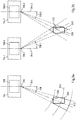
- the position determination by the position determination module 224 is exemplified with the aid of Figures 3a and 3b described in more detail.
- the position is determined based on the first angular datum and the RSSI (which can be determined in a known manner, for example, by an RSSI module, not shown, of the array antenna arrangement 208) of the information signal received by the approach antennas 210.
- the position is determined in a polar coordinate system (it goes without saying that in practice a spherical coordinate system can also be provided).
- the origin 336 of the polar coordinate system forms in the present case by way of example the center point of array antenna assembly 308 (e.g., a centrally located approach antenna).
- the reference straight line 344 which lies in a horizontal plane, extends perpendicular to a front side of the height limitation device 314 (e.g. in the form of a height limitation bar 314).
- the reference straight line 344 is in particular the polar axis 344 of the polar coordinate system.
- the position data (e.g. in the form ⁇ r, ⁇ ) of the mobile terminal 330 can be formed by the first angular datum 338 and the radius 340, which is determined from the RSSI.
- an angle data range and a radius range can be specified in which the measurement tolerances are taken into account when determining the radius and angle.
- the position data can therefore in particular indicate the area 342 in which the mobile terminal device 330 (and thus the vehicle in which the mobile terminal device 330 is located) is currently located.
- the position is determined based on the first angular datum 338.1 and a further angular datum 338.2, which was determined by an adjacent group antenna arrangement 308.2.
- Adjacent means in particular that the group antenna arrangement 308.2 is located at least in the same access arrangement.
- the group antenna arrangements 308.1, 308.2 are preferably immediately adjacent.
- the adjacent group antenna arrangement 308.2 can be assigned to an adjacent passage.
- the position determination module 224 determines in particular the point of intersection of the first angle data 338.1 and the further angle data 338.2, as from FIG Figure 3b can be seen. In order to take the measurement tolerances into account, the respective angle data range can be used and the intersection range 342 determined will. The position data can therefore in particular indicate the area 342 in which the mobile terminal device 330 (and thus the vehicle in which the mobile terminal device 330 is located) is currently located.
- the further angle data 338.2 can in particular be provided via the receiving device interface 226.
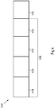
- FIG. 11 shows a preferred embodiment of an information signal 446 in accordance with the present application.
- information signal 446 may preferably be a Bluetooth version 5.X (or higher) information signal.
- the information signal 446 is formed from a modulated signal section 458 and an unmodulated signal section 456.
- the modulated signal section 458 contains data content and can, for example, be a preamble 448 (e.g. 1 or 2 octets), an access-address field (e.g. 4 octets), a PDU ( Payload Data Unit) (e.g. 2 to 248 octets) and a CRC (Cyclic Redundancy Check) (e.g. 3 octets).
- a preamble 448 e.g. 1 or 2 octets
- an access-address field e.g. 4 octets
- PDU Payload Data Unit
- CRC Cyclic Redundancy Check
- the unmodulated signal section 456 can comprise between 1 and 300 microseconds of unmodulated signal duration, preferably 16 to 160 microseconds.
- the unmodulated signal section 456 can be a CTE (Constant Tone Extension). In particular, this is not removed from the information signal 446 even in a so-called “whitening process”.
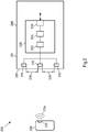
- FIG. 5 shows a schematic view of a further exemplary embodiment of a parking system 500 according to the present application. To avoid repetition, essentially only the differences from the previous exemplary embodiments are described below, and otherwise reference is made to the previous statements. It should also be noted that the access device has not been shown for the sake of a better overview. That The illustrated embodiment is based in particular on the "Angle of Departure" scheme.
- the array antenna arrangement 508 includes an approach transmitter 560 that is electrically coupled to the approach antennas 510.
- the approach transmission device 560 is set up in particular to control the transmission of a first group information signal 562.
- the group information signal 562 is formed from a plurality of individual information signals 564.1, 564.2, 564.3, which are each emitted by the approach antennas 510.
- An individual information signal 564.1, 564.2, 564.3 can be formed, for example, as in FIG Figure 4 shown.
- the approach transmission device 560 can be set up to control the transmission of the first group information signal 562 in such a way that the respective unmodulated signal sections of the individual information signals 564.1, 564.2, 564.3 of the first group information signal each have a specific phase relationship have to each other. This can be known to a terminal receiving device 566. In particular, this can be taken into account when determining the position.
- the mobile terminal device 530 has a terminal device receiving device 566, which is formed in particular as a parking application 566.
- the parking application 566 is installed in particular as an app on the mobile terminal device 530 (for example a smartphone 530).
- the parking application 566 comprises a plurality of software modules 568, 570, 572.
- an antenna 532 can provide (digital) antenna signals to a receiving module 568 (via further elements such as filters, A / D converters, amplifiers, etc.).
- the (digital) antenna signals are based on the received individual information signals 564.1, 564.2, 564.3.
- the receiving module 568 is set up to receive antenna signals that are at least based on the respective unmodulated signal sections of individual information signals 564.1, 564.2, 564.3 of a group information signal 562 received by an antenna 532 of the mobile terminal 530.
- the group information signal 562 from a group antenna arrangement 508 with a plurality of adjacent access antennas 510.
- the group antenna arrangement 508 is assigned to a specific access device, as has been described above.
- At least one position determination module 572 is provided in the parking application 566, set up to determine position data of the mobile terminal 530 receiving the group information signal 562. This takes place in particular based on the unmodulated signal section of the group information signal 562, i.e. the respective unmodulated signal sections of the respective individual information signals 564.1, 564.2, 564.3 of the group information signal 562.
- the parking application 566 can in particular have a demodulation module 570.
- the demodulation module 570 can demodulate the antenna signals (in particular in a manner analogous to the previous explanations). In particular, an amplitude data and a phase data can be provided for each antenna signal. The data can be provided to the position determination module 572.
- the position determination module 572 can determine the position data of the mobile terminal 530 (in particular in a manner analogous to the previous explanations), at least based on the provided amplitude and phase data of a first group antenna signal 562.
- the position determination can be based on an RSSI of the group antenna signal 562. In particular, this can be done in a manner analogous to the explanations relating to Figure 3a take place.
- the position determination module 572 can be set up to determine the position data of the mobile terminal 530 based on the demodulated first antenna signals and on the demodulated second antenna signals of a further group information signal.
- the further group information signal can have been transmitted by a further group antenna arrangement arranged adjacent to the first group antenna arrangement (which can in particular be assigned to at least the same access arrangement).
- the respective individual information signals 564.1, 564.2, 564.3 in the corresponding modulated signal sections can contain at least one (system-wide, one-to-one) access device identifier as data content. Based on the access device identifier, the position determination module 572 can identify the transmitting access device or the group antenna arrangement 508 assigned to this access device.
- the position data of the mobile terminal device 530 are determined by the position determination module 572.
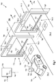
- the Figure 6 shows a schematic view of a further exemplary embodiment of a parking system 600 according to the present application. To avoid repetition, essentially only the differences from the previous exemplary embodiments are described below, and otherwise reference is made to the previous statements, in particular to the statements relating to Figure 5 . The illustrated embodiment is based in particular on the "Angle of Departure" scheme.
- the parking system 600 has at least one access arrangement 674 with a first access device 602.1 and at least one further access device 602.2.
- a multiplicity of further access devices can preferably be provided, and / or the parking system 600 can comprise a multiplicity of access arrangements (arranged at a distance from one another).
- an access arrangement 674 can be provided at at least one entrance 605 of the parking device and at least one further access arrangement can be provided at at least one exit of the parking device.
- a group antenna arrangement 608.1, 608.2 can (uniquely) be assigned to each access device 602.1, 602.2.
- a respective group antenna arrangement 608.1, 608.2 can be arranged on a respective height restriction device 614.1, 614.2.
- the respective height restriction device 614.1, 614.2 can be assigned to a respective access device 602.1, 602.2 (in that, for example, the respective height restriction device 614.1, 614.2 and the respective access device 602.1, 602.2 have a common passage).
- the structure of the access antennas (not shown in detail for the sake of a better overview) can be formed in the same way.
- the same group antenna arrangement 608.1, 608.2 can be arranged in each case.
- the access antennas can be arranged in or on each height restriction device 614.1, 614.2 at the same point.
- all of the height restriction devices 614.1, 614.2 and access devices 602.1, 602.2 of the access arrangement 674 are arranged in relation to one another in a predetermined manner.
- the horizontal one is between each immediately adjacent group antenna arrangement 608.1, 608.2 Distance 686 equal.
- the (vertical) height 687 of each directly adjacent group antenna arrangement 608.1, 608.2 can preferably be the same.
- this can be the case with every access arrangement of the parking system.
- This allows the electrical components and / or the position determination algorithm to be set more easily. Therefore, in particular, an access arrangement can be installed more easily.
- the so-called “fine tuning” at the installation site of the access arrangement can be carried out with less effort or can even be omitted entirely.
- other geometrical arrangements can also be provided in the case of other variants. However, these can be assumed to be known in the system.
- each access device 602.1, 602.2 in the present case comprises a local control module 676.1, 676.2.
- the local control module 676.1, 676.2 is set up to control the respective access device 602.1, 602.2, in particular to control or monitor the passage through the passage 605 through the access device 602.1, 602.2 from the first area 604 to the further area 606.
- the control module 676.1 , 676.2 enable or block a vehicle 618 from driving through the respective access device 602.1, 602.2 (as will be explained in more detail below by way of example).
- an access arrangement can also comprise only a single control module for controlling all of the access devices of the access arrangement.
- each access device 602.1, 602.2 is assigned a vehicle detection device 671.1, 671.2.
- vehicle detection device 671.1, 671.2 In particular, induction loops 671.1, 671.2 are provided here.
- the present parking system 600 comprises a back-end system 678.
- the back-end system 678 can be formed from one or more server (s) which for example is / are arranged remotely.
- the backend system 678 has at least one communication module 680, 688.
- the at least one communication module 680, 688 is set up to communicate with a control module 676.1, 676.2 of an access device 602.1, 602.2 and / or with a mobile terminal 630. In the event that different transmission technologies are provided, a corresponding number of different communication modules 680, 688 be provided.
- the backend system 678, the control modules 676.1, 676.2, the vehicle detection devices 671.1, 671.2 and / or the group antenna arrangements 608.1, 608.2 can communicate via at least one (wireless and / or wired) communication network 685.
- the illustrated mobile terminal 630 has, in particular, a parking application 666 described above (for the sake of a better overview, the individual modules are not shown).
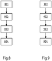
- FIG. 10 shows a diagram of an exemplary embodiment of a method according to the present application, in particular for operating or executing a parking application 666.
- each group antenna arrangement 608.1, 608.2 (periodically, almost continuously) transmits the group information signals 662.1, 662.2 mentioned.
- a mobile terminal device 630 comes within range (which in particular covers at least the access sections 604.1, 604.2 of the first area 604) of at least one group antenna arrangement 608.1, 608.2, a (Bluetooth) antenna 632 receives the group information signal 662.1, 662.2 (or the respective individual information signals) .
- the antenna 632 of the mobile terminal 630 (and others Components such as filters, amplifiers, A / D converters, etc.) can provide the respective antenna signals to an activated parking application 666 or a terminal device receiving device 666.
- the antenna signals mentioned are received, in particular by at least one receiving module (which can in particular be formed as a bidirectional interface). These are based at least on the respective unmodulated signal sections of individual information signals of a group information signal 662.1, 662.2 received by an antenna 632 of the mobile terminal 630.
- step 802 and 803 position data of the mobile terminal device 630 received the group information signal (and thus of the corresponding vehicle 618) is determined. This takes place at least based on the unmodulated signal sections of the individual information signals.
- step 802 an I&Q demodulation can be carried out by a demodulation module of the parking application 666 in the manner described above.
- the (current) position data of the mobile terminal device 630 can then be determined in step 803 in the manner described above.
- the parking application 666 sends out at least the determined position data.
- a data record can be sent out containing the access device identifier received by the at least one group information signal, at least one authentication date, such as a user identifier (e.g. a user name, vehicle registration number of the user's vehicle, a terminal identifier of the user's mobile terminal device, such as the IMEI, etc.) and / or parking ticket information.
- a user identifier e.g. a user name, vehicle registration number of the user's vehicle, a terminal identifier of the user's mobile terminal device, such as the IMEI, etc.
- further data can be included, such as a time stamp.
- This data record can be transmitted to the backend system 678 via a communication network 682.
- the backend system 678 can check the user identification and / or the authentication date. If the user is authorized to drive through the access device 602.1, 602.2 named in the data record (i.e. to drive into the parking device in the present example), the backend system 678 can at least send the position data of the mobile terminal 630 to the corresponding control module 676.1, 676.2 (based on the access device identifier ) forward onto.
- a release date (and / or a user identifier) can be transmitted, which indicates that the user and thus the corresponding vehicle 618 are authorized to drive through.
- steps 801 to 804 can preferably be carried out periodically, almost continuously, in order to obtain a movement profile of the mobile terminal device 630 and thus of the vehicle 618.
- the correct access device 602.1, 602.2 for the corresponding vehicle 618 can be released at the right time in a reliable manner (not too early, so that an unauthorized person or an unauthorized vehicle could drive through the access device 602.1, 602.2; and also not too late, so that there is (almost) no delay in vehicle movement). This is made possible by the very precise determination of the position of the vehicle 618 of the user of the mobile terminal 630 in accordance with the registration.
- an access device 602.1, 602.2 can have an interface device (a reading device) in order to assign an authentication data item, for example in the form of a readable parking code record and initiate a check (e.g. magnetic stripe code, barcode, QR code, RFID identifier, another readable user or mobile device identifier, etc.).
- an access device 602.1, 602.2 can have an output device in order to output a media-bound short-term parking ticket of a known type (eg magnetic stripe ticket, barcode ticket, chipcoin etc.) to a user.
- FIG. 3 shows a schematic view of a further exemplary embodiment of a parking system 700 according to the present application.
- a further exemplary embodiment of a parking system 700 according to the present application.
- the illustrated embodiment is based in particular on the "Angle of Arrival" scheme.
- group antenna arrangements 708.1, 708.2 assigned to the access devices 702.1, 702.2 are assigned, each of which has an access receiving device.
- the mobile terminal 730 has an (activated) parking application that causes an information signal to be transmitted.
- the parking application can be awakened, i.e. activated, by receiving a first (BT) beacon signal.
- the same signal or a further (BT) beacon signal can cause the parking application to cause the information signal 734 to be transmitted (periodically, almost continuously).
- Figure 9 shows a diagram of an exemplary embodiment of a method according to the present application, in particular for operating a parking system 700, in particular the access devices 702.1, 702.2.
- an activated parking application of a mobile terminal device 730 can cause an information signal 734 (periodically, almost continuously) to be transmitted.
- the information signal 734 can contain at least one authentication data item as data content, such as a user identifier (e.g. a user name, vehicle registration number of the user's vehicle, a terminal identifier of the user's mobile terminal, such as the IMEI, etc.) and / or a parking Ticket information.
- a user identifier e.g. a user name, vehicle registration number of the user's vehicle, a terminal identifier of the user's mobile terminal, such as the IMEI, etc.
- the access antennas receive at least one group antenna arrangement 708.1, 708.2, which are assigned to an access device 702.1, 702.2, of the information signal 734.
- the information signal 734 contains at least one unmodulated signal section.
- the access antennas provide antenna signals which are each based on the unmodulated signal section of the information signal, as has already been described.
- step 903 position data of the mobile terminal 730 transmitting the information signal 734 is determined, at least based on the unmodulated signal section of the information signal 734. As already described, a demodulation and then a position determination can in particular take place first.
- the determined position data can be made available to a control module 776.1, 776.2 in step 904.
- the data content of the information signal 734 can be made available to the control module 776.1, 776.2.
- the authorization of the user to drive through the access device 702.1, 702.2 can be checked based on the at least one authentication date.
- communication can take place with the backend system 778, which can in particular carry out a data comparison between the authentication date and stored user data.
- the additional sensor data possibly received via a further input 784 of the backend system 778 and / or the communication module 782, such as camera data, RF sensor data and / or vehicle detection data of the vehicle detection devices 771.1, 772.2 etc., can be made available.
- the control module 776.1, 776.2 can enable the access device 702.1, 702.2 to drive through the passage 705, based on the position data (and possibly further sensor data) and, for example, the check result.
- a release can only take place if the verification of the authentication data shows that the user is authorized to drive through, e.g. to drive into a parking device or to drive out of a parking device, and the position data show that the user has the access device 702.1, 702.2 actually wants to happen. Otherwise the access device 702.1, 702.2 can remain blocked.
- steps 901 to 904 can preferably be carried out periodically, almost continuously, in order to obtain a movement profile of the mobile terminal device 730 and thus of the corresponding vehicle 718.
- the correct access device 702.1, 702.2 can be released for the user at the right time in a reliable manner (not too early, so that an unauthorized person or an unauthorized vehicle could drive through the access device 702.1, 702.2; and also not too late, so that There is (almost) no delay in vehicle movement). This is made possible by the very precise determination of the position of the vehicle 718 of the user of the mobile terminal 730 in accordance with the registration.
- an access device 702.1, 702.2 can have an interface device (a reading device) to allow a Record the authentication date, for example in the form of a readable access code, and initiate a check (e.g. magnetic stripe code, barcode, QR code, RFID identifier, another readable user or mobile device identifier, etc.).
- an access device 702.1, 702.2 can have an output device in order to output a media-bound short-term parking ticket of a known type (eg magnetic stripe ticket, barcode ticket, chipcoin etc.) to a user.
Landscapes
- Business, Economics & Management (AREA)
- Finance (AREA)
- Physics & Mathematics (AREA)
- General Physics & Mathematics (AREA)
- Devices For Checking Fares Or Tickets At Control Points (AREA)
- Traffic Control Systems (AREA)
Applications Claiming Priority (1)
| Application Number | Priority Date | Filing Date | Title |
|---|---|---|---|
| DE102020113243.3A DE102020113243A1 (de) | 2020-05-15 | 2020-05-15 | Parksystem |
Publications (1)
| Publication Number | Publication Date |
|---|---|
| EP3910603A1 true EP3910603A1 (fr) | 2021-11-17 |
Family
ID=75529887
Family Applications (1)
| Application Number | Title | Priority Date | Filing Date |
|---|---|---|---|
| EP21168391.7A Pending EP3910603A1 (fr) | 2020-05-15 | 2021-04-14 | Système de stationnement |
Country Status (2)
| Country | Link |
|---|---|
| EP (1) | EP3910603A1 (fr) |
| DE (1) | DE102020113243A1 (fr) |
Cited By (1)
| Publication number | Priority date | Publication date | Assignee | Title |
|---|---|---|---|---|
| CN115323957A (zh) * | 2022-08-31 | 2022-11-11 | 喜鹊云(浙江)数字科技有限公司 | 一种停车场道闸组件 |
Citations (3)
| Publication number | Priority date | Publication date | Assignee | Title |
|---|---|---|---|---|
| EP3407307A1 (fr) | 2017-05-23 | 2018-11-28 | Scheidt & Bachmann GmbH | Système de stationnement et son procédé de fonctionnement |
| CN110706505A (zh) * | 2019-09-03 | 2020-01-17 | 广东昇辉电子控股有限公司 | 一种基于蓝牙5.1出发角的地下车库寻车系统 |
| CN112102645A (zh) * | 2020-08-31 | 2020-12-18 | 南京创维信息技术研究院有限公司 | 一种基于蓝牙aoa技术的室内定位寻车系统及方法 |
Family Cites Families (1)
| Publication number | Priority date | Publication date | Assignee | Title |
|---|---|---|---|---|
| DE102015214826A1 (de) | 2015-08-04 | 2017-02-09 | Robert Bosch Gmbh | Verfahren und System zum Lokalisieren eines sich innerhalb eines Parkplatzes befindenden Fahrzeugs |
-
2020
- 2020-05-15 DE DE102020113243.3A patent/DE102020113243A1/de active Pending
-
2021
- 2021-04-14 EP EP21168391.7A patent/EP3910603A1/fr active Pending
Patent Citations (3)
| Publication number | Priority date | Publication date | Assignee | Title |
|---|---|---|---|---|
| EP3407307A1 (fr) | 2017-05-23 | 2018-11-28 | Scheidt & Bachmann GmbH | Système de stationnement et son procédé de fonctionnement |
| CN110706505A (zh) * | 2019-09-03 | 2020-01-17 | 广东昇辉电子控股有限公司 | 一种基于蓝牙5.1出发角的地下车库寻车系统 |
| CN112102645A (zh) * | 2020-08-31 | 2020-12-18 | 南京创维信息技术研究院有限公司 | 一种基于蓝牙aoa技术的室内定位寻车系统及方法 |
Non-Patent Citations (1)
| Title |
|---|
| ANONYMOUS: "Bestandsverfolgung mit Bluetooth 5.1: Teil 1 | DigiKey", 25 July 2019 (2019-07-25), pages 1 - 10, XP055843908, Retrieved from the Internet <URL:https://www.digikey.de/de/articles/use-bluetooth-5-1-enabled-platforms-part-1> [retrieved on 20210922] * |
Cited By (2)
| Publication number | Priority date | Publication date | Assignee | Title |
|---|---|---|---|---|
| CN115323957A (zh) * | 2022-08-31 | 2022-11-11 | 喜鹊云(浙江)数字科技有限公司 | 一种停车场道闸组件 |
| CN115323957B (zh) * | 2022-08-31 | 2023-11-14 | 喜鹊云(浙江)数字科技有限公司 | 一种停车场道闸组件 |
Also Published As
| Publication number | Publication date |
|---|---|
| DE102020113243A1 (de) | 2021-11-18 |
Similar Documents
| Publication | Publication Date | Title |
|---|---|---|
| DE102016206539B4 (de) | Verfahren zur passiven Zugangskontrolle | |
| EP3131065A1 (fr) | Procede et systeme de controle d'acces | |
| DE112020004119T5 (de) | Multiplex-Antennenschaltkreisnetzwerk für ein Ultra-Hochfrequenz-Niedrigenergie-Telefon als ein Schlüsselzugang zu einem Fahrzeug | |
| EP3051502A1 (fr) | Systeme de controle d'entree de stationnement et procede de controle de l'entree dans un stationnement | |
| DE102014102271A1 (de) | Verfahren und Einrichtung zum Erteilen einer Zutrittserlaubnis | |
| EP2835788A1 (fr) | Procédé de contrôle d'entrée et de sortie pour des parcs de stationnement et installations de stationnement | |
| WO2017050595A1 (fr) | Procédé et dispositif de détermination de la position absolue d'un véhicule | |
| DE102013217869A1 (de) | Verfahren und Kommunikationsvorrichtung zur Validierung eines Dateninhalts eines drahtlos empfangenen Kommunikationssignals sowie Verwendung der Kommunikationsvorrichtung | |
| EP3955219A2 (fr) | Procédé de fonctionnement d'un dispositif de stationnement | |
| EP3261060B1 (fr) | Procédés de contrôle d'accès dans un système de contrôle d'accès pour personnes ou véhicules automobiles et système de contrôle d'accès | |
| EP3910606A1 (fr) | Système d'accès pourvu d'au moins un portail | |
| EP3407307B1 (fr) | Système de stationnement et son procédé de fonctionnement | |
| DE102017001092A1 (de) | Schutz gegen einen Relayangriff | |
| EP3910603A1 (fr) | Système de stationnement | |
| EP3146355B1 (fr) | Système d'appareils médicaux et procédé pour localiser des appareils médicaux et des unités de commande mobiles de ce système d'appareils médicaux | |
| EP2949096B1 (fr) | Production de donnés de position au moyen d'un protocole délimiteur de distance | |
| WO2017129188A1 (fr) | Procédé et système de contrôle d'accès | |
| EP2081140A1 (fr) | Procédé et système destinés à la protection d'une transaction | |
| EP3335199A1 (fr) | Procédé et dispositif pour effectuer un contrôle de personnes | |
| EP3929889A1 (fr) | Système d'admission de carburant | |
| EP3425610B1 (fr) | Procédé et système pour détection de véhicules dans un parking | |
| WO2019053079A1 (fr) | Émetteur-récepteur avec un capteur pour le calcul d'une information de position d'une antenne d'un autre émetteur-récepteur | |
| EP3817406B1 (fr) | Procédé de fonctionnement d'une application de service installée sur un dispositif terminal mobile | |
| DE102015209839A1 (de) | Vorrichtung, System und Verfahren zum Bestimmen einer Position eines mobilen Geräts während eines Bezahlvorgangs | |
| DE102022112554A1 (de) | Parksystem |
Legal Events
| Date | Code | Title | Description |
|---|---|---|---|
| PUAI | Public reference made under article 153(3) epc to a published international application that has entered the european phase |
Free format text: ORIGINAL CODE: 0009012 |
|
| STAA | Information on the status of an ep patent application or granted ep patent |
Free format text: STATUS: THE APPLICATION HAS BEEN PUBLISHED |
|
| AK | Designated contracting states |
Kind code of ref document: A1 Designated state(s): AL AT BE BG CH CY CZ DE DK EE ES FI FR GB GR HR HU IE IS IT LI LT LU LV MC MK MT NL NO PL PT RO RS SE SI SK SM TR |
|
| B565 | Issuance of search results under rule 164(2) epc |
Effective date: 20211007 |
|
| STAA | Information on the status of an ep patent application or granted ep patent |
Free format text: STATUS: REQUEST FOR EXAMINATION WAS MADE |
|
| 17P | Request for examination filed |
Effective date: 20220428 |
|
| RBV | Designated contracting states (corrected) |
Designated state(s): AL AT BE BG CH CY CZ DE DK EE ES FI FR GB GR HR HU IE IS IT LI LT LU LV MC MK MT NL NO PL PT RO RS SE SI SK SM TR |
|
| STAA | Information on the status of an ep patent application or granted ep patent |
Free format text: STATUS: EXAMINATION IS IN PROGRESS |
|
| P01 | Opt-out of the competence of the unified patent court (upc) registered |
Effective date: 20230427 |
|
| 17Q | First examination report despatched |
Effective date: 20230531 |