EP3910262A1 - Refrigeration cycle device - Google Patents
Refrigeration cycle device Download PDFInfo
- Publication number
- EP3910262A1 EP3910262A1 EP19908451.8A EP19908451A EP3910262A1 EP 3910262 A1 EP3910262 A1 EP 3910262A1 EP 19908451 A EP19908451 A EP 19908451A EP 3910262 A1 EP3910262 A1 EP 3910262A1
- Authority
- EP
- European Patent Office
- Prior art keywords
- refrigerant
- heat exchanger
- internal heat
- refrigeration cycle
- inner pipe
- Prior art date
- Legal status (The legal status is an assumption and is not a legal conclusion. Google has not performed a legal analysis and makes no representation as to the accuracy of the status listed.)
- Granted
Links
Images


Classifications
-
- F—MECHANICAL ENGINEERING; LIGHTING; HEATING; WEAPONS; BLASTING
- F25—REFRIGERATION OR COOLING; COMBINED HEATING AND REFRIGERATION SYSTEMS; HEAT PUMP SYSTEMS; MANUFACTURE OR STORAGE OF ICE; LIQUEFACTION SOLIDIFICATION OF GASES
- F25B—REFRIGERATION MACHINES, PLANTS OR SYSTEMS; COMBINED HEATING AND REFRIGERATION SYSTEMS; HEAT PUMP SYSTEMS
- F25B40/00—Subcoolers, desuperheaters or superheaters
- F25B40/02—Subcoolers
-
- F—MECHANICAL ENGINEERING; LIGHTING; HEATING; WEAPONS; BLASTING
- F25—REFRIGERATION OR COOLING; COMBINED HEATING AND REFRIGERATION SYSTEMS; HEAT PUMP SYSTEMS; MANUFACTURE OR STORAGE OF ICE; LIQUEFACTION SOLIDIFICATION OF GASES
- F25B—REFRIGERATION MACHINES, PLANTS OR SYSTEMS; COMBINED HEATING AND REFRIGERATION SYSTEMS; HEAT PUMP SYSTEMS
- F25B1/00—Compression machines, plants or systems with non-reversible cycle
-
- F—MECHANICAL ENGINEERING; LIGHTING; HEATING; WEAPONS; BLASTING
- F25—REFRIGERATION OR COOLING; COMBINED HEATING AND REFRIGERATION SYSTEMS; HEAT PUMP SYSTEMS; MANUFACTURE OR STORAGE OF ICE; LIQUEFACTION SOLIDIFICATION OF GASES
- F25B—REFRIGERATION MACHINES, PLANTS OR SYSTEMS; COMBINED HEATING AND REFRIGERATION SYSTEMS; HEAT PUMP SYSTEMS
- F25B40/00—Subcoolers, desuperheaters or superheaters
- F25B40/06—Superheaters
-
- F—MECHANICAL ENGINEERING; LIGHTING; HEATING; WEAPONS; BLASTING
- F28—HEAT EXCHANGE IN GENERAL
- F28D—HEAT-EXCHANGE APPARATUS, NOT PROVIDED FOR IN ANOTHER SUBCLASS, IN WHICH THE HEAT-EXCHANGE MEDIA DO NOT COME INTO DIRECT CONTACT
- F28D7/00—Heat-exchange apparatus having stationary tubular conduit assemblies for both heat-exchange media, the media being in contact with different sides of a conduit wall
- F28D7/10—Heat-exchange apparatus having stationary tubular conduit assemblies for both heat-exchange media, the media being in contact with different sides of a conduit wall the conduits being arranged one within the other, e.g. concentrically
- F28D7/106—Heat-exchange apparatus having stationary tubular conduit assemblies for both heat-exchange media, the media being in contact with different sides of a conduit wall the conduits being arranged one within the other, e.g. concentrically consisting of two coaxial conduits or modules of two coaxial conduits
-
- F—MECHANICAL ENGINEERING; LIGHTING; HEATING; WEAPONS; BLASTING
- F28—HEAT EXCHANGE IN GENERAL
- F28F—DETAILS OF HEAT-EXCHANGE AND HEAT-TRANSFER APPARATUS, OF GENERAL APPLICATION
- F28F1/00—Tubular elements; Assemblies of tubular elements
- F28F1/10—Tubular elements and assemblies thereof with means for increasing heat-transfer area, e.g. with fins, with projections, with recesses
- F28F1/40—Tubular elements and assemblies thereof with means for increasing heat-transfer area, e.g. with fins, with projections, with recesses the means being only inside the tubular element
-
- F—MECHANICAL ENGINEERING; LIGHTING; HEATING; WEAPONS; BLASTING
- F28—HEAT EXCHANGE IN GENERAL
- F28F—DETAILS OF HEAT-EXCHANGE AND HEAT-TRANSFER APPARATUS, OF GENERAL APPLICATION
- F28F13/00—Arrangements for modifying heat-transfer, e.g. increasing, decreasing
- F28F13/18—Arrangements for modifying heat-transfer, e.g. increasing, decreasing by applying coatings, e.g. radiation-absorbing, radiation-reflecting; by surface treatment, e.g. polishing
- F28F13/185—Heat-exchange surfaces provided with microstructures or with porous coatings
- F28F13/187—Heat-exchange surfaces provided with microstructures or with porous coatings especially adapted for evaporator surfaces or condenser surfaces, e.g. with nucleation sites
-
- F—MECHANICAL ENGINEERING; LIGHTING; HEATING; WEAPONS; BLASTING
- F25—REFRIGERATION OR COOLING; COMBINED HEATING AND REFRIGERATION SYSTEMS; HEAT PUMP SYSTEMS; MANUFACTURE OR STORAGE OF ICE; LIQUEFACTION SOLIDIFICATION OF GASES
- F25B—REFRIGERATION MACHINES, PLANTS OR SYSTEMS; COMBINED HEATING AND REFRIGERATION SYSTEMS; HEAT PUMP SYSTEMS
- F25B2400/00—Component parts or details not otherwise provided for in this subclass
- F25B2400/05—Compression system with heat exchange between particular parts of the system
- F25B2400/054—Compression system with heat exchange between particular parts of the system between the suction tube of the compressor and another part of the cycle
-
- F—MECHANICAL ENGINEERING; LIGHTING; HEATING; WEAPONS; BLASTING
- F25—REFRIGERATION OR COOLING; COMBINED HEATING AND REFRIGERATION SYSTEMS; HEAT PUMP SYSTEMS; MANUFACTURE OR STORAGE OF ICE; LIQUEFACTION SOLIDIFICATION OF GASES
- F25B—REFRIGERATION MACHINES, PLANTS OR SYSTEMS; COMBINED HEATING AND REFRIGERATION SYSTEMS; HEAT PUMP SYSTEMS
- F25B2500/00—Problems to be solved
- F25B2500/09—Improving heat transfers
-
- F—MECHANICAL ENGINEERING; LIGHTING; HEATING; WEAPONS; BLASTING
- F28—HEAT EXCHANGE IN GENERAL
- F28D—HEAT-EXCHANGE APPARATUS, NOT PROVIDED FOR IN ANOTHER SUBCLASS, IN WHICH THE HEAT-EXCHANGE MEDIA DO NOT COME INTO DIRECT CONTACT
- F28D21/00—Heat-exchange apparatus not covered by any of the groups F28D1/00 - F28D20/00
- F28D2021/0019—Other heat exchangers for particular applications; Heat exchange systems not otherwise provided for
- F28D2021/0068—Other heat exchangers for particular applications; Heat exchange systems not otherwise provided for for refrigerant cycles
Definitions
- the present invention relates to a refrigeration cycle apparatus.
- R32 refrigerant or R410A refrigerant has been conventionally used as refrigerant for a refrigeration cycle apparatus.
- a refrigeration cycle apparatus in which R290 (propane) refrigerant having a global warming potential (GWP) smaller than that of R32 refrigerant or R410A refrigerant is used in a refrigerant circuit in order to reduce an influence on global warming.
- GWP global warming potential
- a refrigeration cycle apparatus including an internal heat exchanger for increasing a cooling capacity.
- Japanese Patent Laying-Open No. 2008-164245 (PTL 1) describes a refrigeration cycle apparatus including propane as refrigerant for use in a refrigerant circuit and including an internal heat exchanger.
- the refrigeration cycle apparatus described in this publication includes a compressor, a condenser, a heat exchanger, and an evaporator.
- the heat exchanger corresponds to the internal heat exchanger.
- the internal heat exchanger includes an inner pipe, and an outer pipe in which the inner pipe is inserted.
- the refrigerant delivered from the compressor through the condenser to the internal heat exchanger is delivered to the evaporator through the inner pipe in the heat exchanger.
- the refrigerant delivered to the evaporator returns to the compressor through the outer pipe in the internal heat exchanger. Heat exchange is performed between the refrigerant flowing through the inner pipe and the refrigerant flowing through the outer pipe in the internal heat exchanger.
- the publication above does not describe that the refrigerant flowing inside the outer pipe and outside the inner pipe of the internal heat exchanger is entirely gas refrigerant in the refrigeration cycle apparatus described in the publication above.
- the refrigerant flowing inside the outer pipe and outside the inner pipe of the internal heat exchanger includes liquid refrigerant, it is difficult to increase a superheat degree of the refrigerant at an inlet of the compressor. Therefore, it is difficult to increase a coefficient of performance (COP), which is a ratio of consumed electric power to a capacity of a refrigeration cycle apparatus.
- COP coefficient of performance
- the refrigerant flowing inside the outer pipe and outside the inner pipe of the internal heat exchanger includes liquid refrigerant, it is difficult to reduce an amount of the refrigerant in the internal heat exchanger.
- the present invention has been made in view of the above-described problem, and an object of the present invention is to provide a refrigeration cycle apparatus in which refrigerant having a small global warming potential can be used to increase a coefficient of performance of the refrigeration cycle apparatus and reduce an amount of the refrigerant in an internal heat exchanger.
- a refrigeration cycle apparatus of the present invention includes: a refrigerant circuit; and refrigerant.
- the refrigerant circuit includes a compressor, a condenser, an expansion valve, an evaporator, and an internal heat exchanger.
- the refrigerant flows in the refrigerant circuit in order of the compressor, the condenser, the internal heat exchanger, the expansion valve, the evaporator, and the internal heat exchanger.
- the refrigerant is a hydrocarbon refrigerant.
- the internal heat exchanger includes: an inner pipe connected to the condenser and the expansion valve; and an outer pipe connected to the evaporator and the compressor, the inner pipe being inserted in the outer pipe.
- the internal heat exchanger is configured to cause heat exchange between the refrigerant flowing inside the inner pipe in a direction from the condenser toward the expansion valve, and the refrigerant flowing inside the outer pipe and outside the inner pipe in a direction from the evaporator toward the compressor.
- the refrigerant flowing inside the outer pipe and outside the inner pipe is entirely gas.
- the refrigerant is a hydrocarbon refrigerant and the refrigerant flowing inside the outer pipe and outside the inner pipe of the internal heat exchanger is entirely gas. Therefore, the refrigerant having a small global warming potential can be used. In addition, a coefficient of performance of the refrigeration cycle apparatus can be increased. Furthermore, an amount of the refrigerant in the internal heat exchanger can be reduced.
- FIG. 1 is a configuration diagram showing the refrigeration cycle apparatus according to the first embodiment of the present invention.
- the refrigeration cycle apparatus according to the first embodiment of the present invention is, for example, an air conditioner.
- refrigeration cycle apparatus 1 according to the first embodiment of the present invention includes a refrigerant circuit 2, a controller 3, a condenser fan 10, an evaporator fan 11, and refrigerant.
- Refrigerant circuit 2 includes a compressor 4, a condenser 5, an expansion valve 6, an evaporator 7, and an internal heat exchanger 8. Compressor 4, condenser 5, expansion valve 6, evaporator 7, and internal heat exchanger 8 are connected by a pipe 9. Refrigerant circuit 2 is thus formed. Refrigerant circuit 2 is configured to circulate the refrigerant. Refrigerant circuit 2 is configured such that a refrigeration cycle is performed in which the refrigerant circulates in order of compressor 4, condenser 5, internal heat exchanger 8, expansion valve 6, evaporator 7, and internal heat exchanger 8 while changing its phase.
- the refrigerant flows in refrigerant circuit 2 in order of compressor 4, condenser 5, internal heat exchanger 8, expansion valve 6, evaporator 7, and internal heat exchanger 8.
- the refrigerant is such that a coefficient of performance of the refrigerant becomes higher as a suction superheat degree (suction SH) of compressor 4 becomes higher.
- the refrigerant is, for example, a hydrocarbon refrigerant (HC refrigerant).
- the refrigerant is, for example, propane (R290), isobutane (R600a), pentane (R601), butane (R600), ethane (R170), or propylene (R1270).
- Controller 3 is configured to control refrigerant circuit 2. Controller 3 is configured to control instruments, devices and the like of refrigeration cycle apparatus 1 by performing computation, instruction and the like. Controller 3 is electrically connected to compressor 4, expansion valve 6, condenser fan 10, evaporator fan 11 and the like and is configured to control operations thereof.
- Compressor 4 is configured to compress and discharge suctioned gaseous refrigerant.
- Compressor 4 is configured to be capacity-variable.
- Compressor 4 is configured such that a frequency is changed based on an instruction from controller 3 to thereby adjust a rotation speed and change a capacity.
- refrigerator oil lubricating oil
- the refrigerator oil is, for example, polyalkylene glycol (PAG)-based oil having an ether bond, polyol ester (POE)-based oil having an ester bond, or the like.
- Condenser 5 is configured to condense the refrigerant compressed by compressor 4. Condenser 5 is connected to compressor 4 and internal heat exchanger 8. Condenser 5 includes a heat transfer tube through which the refrigerant flows. Condenser 5 is, for example, a fin-and-tube-type heat exchanger including a plurality of fins and a circular or flat heat transfer tube passing through the plurality of fins.
- Expansion valve 6 is configured to expand and decompress the liquid refrigerant condensed by condenser 5.
- the liquid refrigerant condensed by condenser 5 is expanded and decompressed by expansion valve 6, and thus, the refrigerant enters a gas-liquid two-phase state at an outlet of expansion valve 6.
- Expansion valve 6 is connected to condenser 5 and evaporator 7.
- Expansion valve 6 is, for example, an electric expansion valve configured to adjust a flow rate of the refrigerant based on an instruction from controller 3. An amount of the refrigerant flowing through expansion valve 6 is adjusted by adjusting a degree of opening of expansion valve 6.
- Evaporator 7 is configured to evaporate the refrigerant decompressed by expansion valve 6.
- Evaporator 7 is connected to expansion valve 6 and internal heat exchanger 8.
- Evaporator 7 includes a heat transfer tube through which the refrigerant flows.
- Evaporator 7 is, for example, a fin-and-tube-type heat exchanger including a plurality of fins and a circular or flat heat transfer tube passing through the plurality of fins.
- Internal heat exchanger 8 is configured to cause heat exchange between the refrigerant on the outlet side of condenser 5 and the refrigerant on the outlet side of evaporator 7. In internal heat exchanger 8, heat exchange is performed between the refrigerant condensed by condenser 5 and the refrigerant evaporated by evaporator 7.
- Pipe 9 connects compressor 4, condenser 5, expansion valve 6, evaporator 7, and internal heat exchanger 8.
- Pipe 9 forms a gas-side refrigerant path and a liquid-side refrigerant path.
- Pipe 9 includes a first pipe portion 9a, a second pipe portion 9b, a third pipe portion 9c, and a fourth pipe portion 9d.
- First pipe portion 9a is connected to condenser 5 and internal heat exchanger 8.
- Second pipe portion 9b is connected to internal heat exchanger 8 and expansion valve 6.
- Third pipe portion 9c is connected to evaporator 7 and internal heat exchanger 8.
- Fourth pipe portion 9d is connected to internal heat exchanger 8 and compressor 4.
- condenser fan 10 is provided in a not-shown outdoor unit. Condenser fan 10 is configured to forcibly deliver outdoor air to condenser 5. Condenser fan 10 is attached to condenser 5 and is configured to supply air as a heat exchange fluid to condenser 5. Condenser fan 10 is configured such that a rotation speed of condenser fan 10 is adjusted based on an instruction from controller 3 to thereby adjust an amount of air flowing around condenser 5 and adjust an amount of heat exchange between the air and the refrigerant.
- Evaporator fan 11 is provided in a not-shown indoor unit. Evaporator fan 11 is configured to forcibly deliver indoor air to evaporator 7. Evaporator fan 11 is attached to evaporator 7 and is configured to supply air as a heat exchange fluid to evaporator 7. Evaporator fan 11 is configured such that a rotation speed of evaporator fan 11 is adjusted based on an instruction from controller 3 to thereby adjust an amount of air flowing around evaporator 7 and adjust an amount of heat exchange between the air and the refrigerant.
- internal heat exchanger 8 is a double-pipe-type heat exchanger.
- Internal heat exchanger 8 includes an inner pipe 8a and an outer pipe 8b.
- Inner pipe 8a has a pipe shape.
- Outer pipe 8b has a pipe shape.
- Inner pipe 8a is inserted in outer pipe 8b. That is, inner pipe 8a is arranged within outer pipe 8b.
- a gap GP is provided between an outer circumferential surface of inner pipe 8a and an inner circumferential surface of outer pipe 8b. Gap GP may have an uniform dimension over an entire circumference in an outer circumferential direction of inner pipe 8a.
- inner pipe 8a is connected to condenser 5 and expansion valve 6.
- Inner pipe 8a is connected to condenser 5 with first pipe portion 9a being interposed, and is connected to expansion valve 6 with second pipe portion 9b being interposed.
- Inner pipe 8a is configured such that the high-pressure-side refrigerant flows therethrough.
- Outer pipe 8b is connected to evaporator 7 and compressor 4.
- Outer pipe 8b is connected to evaporator 7 with third pipe portion 9c being interposed, and is connected to compressor 4 with fourth pipe portion 9d being interposed.
- Outer pipe 8b is configured such that the low-pressure-side refrigerant flows therethrough.
- Internal heat exchanger 8 is configured to cause heat exchange between the refrigerant flowing inside inner pipe 8a in a direction from condenser 5 toward expansion valve 6 and the refrigerant flowing inside outer pipe 8b and outside inner pipe 8a in a direction from evaporator 7 toward compressor 4.
- Internal heat exchanger 8 is configured to cause heat exchange, via a wall surface of inner pipe 8a, between the refrigerant flowing inside inner pipe 8a and the refrigerant flowing inside outer pipe 8b and outside inner pipe 8a.
- Internal heat exchanger 8 is configured to cause heat exchange, via the wall surface of inner pipe 8a, between the refrigerant flowing inside inner pipe 8a and the refrigerant flowing through gap GP.
- the refrigerant flowing inside outer pipe 8b and outside inner pipe 8a is entirely gas.
- the refrigerant flowing through gap GP is entirely gas.
- the refrigerant flowing inside outer pipe 8b and outside inner pipe 8a is entirely in a dry state.
- the gaseous refrigerant compressed by compressor 4 is discharged from compressor 4 and delivered to condenser 5 through pipe 9 serving as the gas-side refrigerant path.
- condenser 5 heat is released from the refrigerant flowing through the heat transfer tube to the air, and the refrigerant is thereby condensed.
- the refrigerant is delivered to internal heat exchanger 8 through first pipe portion 9a serving as the liquid-side refrigerant path.
- the refrigerant delivered to internal heat exchanger 8 through first pipe portion 9a flows through inner pipe 8a of internal heat exchanger 8, and then, is delivered to expansion valve 6 through second pipe portion 9b.
- expansion valve 6 the liquid refrigerant is decompressed to the refrigerant in a gas-liquid two-phase state.
- the refrigerant decompressed by expansion valve 6 is delivered to evaporator 7 through pipe 9 serving as the liquid-side refrigerant path. Thereafter, the refrigerant takes in heat from the air and evaporates in evaporator 7, and then, is delivered to internal heat exchanger 8 through third pipe portion 9c serving as the gas-side refrigerant path.
- the refrigerant delivered to internal heat exchanger 8 through third pipe portion 9c flows through outer pipe 8b of internal heat exchanger 8, and then, returns to compressor 4 through fourth pipe portion 9d.
- internal heat exchanger 8 heat exchange is performed between the refrigerant on the outlet side of condenser 5 (high-pressure-side refrigerant) flowing through inner pipe 8a and the refrigerant on the outlet side of evaporator 7 (low-pressure-side refrigerant) flowing through outer pipe 8b. Since a degree of dryness of the refrigerant at the outlet of evaporator 7 can be reduced by internal heat exchanger 8, the heat transfer performance of evaporator 7 is improved. As a result, a coefficient of performance (COP) of refrigeration cycle apparatus 1 is improved.
- COP coefficient of performance
- the R290 refrigerant is used as one example of the refrigerant.
- Comparative Example 1 is different from refrigeration cycle apparatus 1 according to the first embodiment of the present invention in that the refrigerant is R32.
- the R32 refrigerant has a global warming potential (GWP) greater than that of the R290 refrigerant.
- Comparative Example 1 is different from the refrigeration cycle apparatus according to the first embodiment of the present invention in that the low-pressure-side refrigerant flows through inner pipe 8a and the high-pressure-side refrigerant flows through outer pipe 8b in internal heat exchanger 8. That is, in Comparative Example 1, inner pipe 8a is connected to evaporator 7 and compressor 4 and outer pipe 8b is connected to condenser 5 and expansion valve 6 in internal heat exchanger 8.
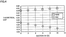
- Fig. 4 is a graph showing a relationship between a theoretical coefficient of performance (hereinafter, referred to as "theoretical COP") and a suction superheat degree (suction SH) of compressor 4 when each of the R290 refrigerant and the R32 refrigerant is used as the refrigerant for refrigerant circuit 2.
- the coefficient of performance (COP) is a ratio of consumed electric power to a capacity of refrigeration cycle apparatus 1.
- the theoretical COP of the R32 refrigerant decreases as the suction superheat degree (suction SH) of compressor 4 increases.
- the theoretical COP of the R290 refrigerant increases as the suction superheat degree (SH) of compressor 4 increases. This is because the R290 refrigerant and the R32 refrigerant are different in properties. That is, as the suction superheat degree (suction SH) of compressor 4 increases, the coefficient of performance of the R290 refrigerant becomes superior to that of the R32 refrigerant.
- the coefficient of performance of the R32 refrigerant is higher when the suction superheat degree (suction SH) of compressor 4 is zero than when the suction superheat degree (suction SH) of compressor 4 is higher than zero. Therefore, in order to increase the coefficient of performance, the low-pressure-side refrigerant is brought into a wet state in internal heat exchanger 8 so as to prevent the suction superheat degree (suction SH) of compressor 4 from becoming higher than zero.
- Fig. 5 is a cross-sectional view showing a flowing state of the refrigerant in internal heat exchanger 8 in Comparative Example 1.
- refrigerant R1 flowing through inner pipe 8a is low-pressure-side refrigerant
- refrigerant R2 flowing through outer pipe 8b is high-pressure-side refrigerant.
- Low-pressure-side refrigerant R1 flowing through inner pipe 8a is in a gas-liquid two-phase state.
- Low-pressure-side refrigerant R1 flowing through inner pipe 8a forms an annular flow.
- gas refrigerant Ra flows through a central portion of inner pipe 8a
- liquid refrigerant Rb flows through an outer portion along the wall surface of inner pipe 8a. Since liquid refrigerant Rb comes into contact with the wall surface of inner pipe 8a serving as a heat transfer surface, the heat transfer performance increases.
- the refrigerant in Comparative Example 1 is the R32 refrigerant
- the global warming potential of the refrigerant is greater than that of the R290 refrigerant. Therefore, in Comparative Example 1, the global warming potential of the refrigerant cannot be reduced.
- Fig. 6 is a cross-sectional view showing a flowing state of the refrigerant in internal heat exchanger 8 in Comparative Example 2.
- refrigerant R1 flowing through inner pipe 8a is low-pressure-side refrigerant
- refrigerant R2 flowing through outer pipe 8b is high-pressure-side refrigerant.
- Comparative Example 2 is different from refrigeration cycle apparatus 1 according to the first embodiment of the present invention.
- the refrigerant in Comparative Example 2 is propane (R290).
- refrigerator oil 20 precipitated on the wall surface of inner pipe 8a of internal heat exchanger 8 serves as a thermal resistance, and thus, the heat transfer performance of internal heat exchanger 8 decreases.
- Figs. 7 and 8 are cross-sectional views showing a flowing state of the refrigerant in internal heat exchanger 8 of refrigeration cycle apparatus 1 according to the first embodiment of the present invention.
- refrigerant R1 flowing through inner pipe 8a is high-pressure-side refrigerant
- refrigerant R2 flowing through outer pipe 8b is low-pressure-side refrigerant.
- the wall surface of inner pipe 8a serves as a heat transfer surface where heat exchange is performed between high-pressure-side refrigerant R1 flowing through inner pipe 8a and low-pressure-side refrigerant R2 flowing through outer pipe 8b in internal heat exchanger 8.
- the wall surface of inner pipe 8a serving as the heat transfer surface where heat exchange is performed between the low-pressure-side refrigerant flowing through outer pipe 8b and the high-pressure-side refrigerant flowing through inner pipe 8a
- an area of the wall surface on which refrigerator oil 20 is precipitated is larger in refrigeration cycle apparatus 1 according to the first embodiment of the present invention than in Comparative Example 2.
- an oil amount of the refrigerator oil precipitated on the wall surface of inner pipe 8a serving as the heat transfer surface decreases. Therefore, the refrigerator oil precipitated on the wall surface of inner pipe 8a serves as a thermal resistance, and thus, a reduction in heat transfer performance of internal heat exchanger 8 can be suppressed.
- the propane (R290) refrigerant is used, and the high-pressure-side refrigerant flows through inner pipe 8a of internal heat exchanger 8 and the low-pressure-side refrigerant flows through outer pipe 8b of internal heat exchanger 8. Furthermore, the refrigerant at the low-pressure-side inlet of internal heat exchanger 8 is in a dry state. That is, the superheat degree of the refrigerant at the low-pressure-side inlet of internal heat exchanger 8 is zero. Therefore, a reduction in heat transfer performance caused by precipitation of the refrigerator oil in internal heat exchanger 8 is suppressed. Thus, the operation with a high coefficient of performance can be achieved in refrigeration cycle apparatus 1.
- the refrigerant is a hydrocarbon refrigerant (HC refrigerant). Therefore, the refrigerant having a small global warming potential (GWP) can be used.
- the refrigerant flowing inside outer pipe 8b and outside inner pipe 8a of internal heat exchanger 8 is entirely gas. Therefore, the superheat degree of the refrigerant at the inlet of compressor 4 can be increased, as compared with the case in which the refrigerant flowing inside outer pipe 8b and outside inner pipe 8a of internal heat exchanger 8 includes liquid refrigerant.
- the coefficient of performance (COP) of refrigeration cycle apparatus 1 can be increased.
- the superheat degree of the refrigerant at the outlet of outer pipe 8b of internal heat exchanger 8 can be increased, as compared with the case in which the refrigerant flowing inside outer pipe 8b and outside inner pipe 8a of internal heat exchanger 8 includes liquid refrigerant. Therefore, the amount of the refrigerant in internal heat exchanger 8 can be reduced.
- the refrigerant is an HC refrigerant. Therefore, the global warming potential (GWP) of the refrigerant can be reduced.
- GWP global warming potential
- expansion valve 6 is an electric expansion valve configured to adjust a flow rate of the refrigerant. Therefore, the flow rate of the refrigerant can be adjusted by the electric expansion valve.
- Refrigeration cycle apparatus 1 according to a second embodiment of the present invention has the same configuration, operation and effect as those of above-described refrigeration cycle apparatus 1 according to the first embodiment of the present invention, unless otherwise stated.
- refrigeration cycle apparatus 1 according to the second embodiment of the present invention is different in a configuration of outer pipe 8b of internal heat exchanger 8 from refrigeration cycle apparatus 1 according to the first embodiment of the present invention.
- a groove 30 is provided in an inner surface of outer pipe 8b of internal heat exchanger 8.
- Groove 30 may be provided over an entire circumference of the inner surface of outer pipe 8b of internal heat exchanger 8.
- Groove 30 may be configured to be serrated.
- Inner pipe 8a of internal heat exchanger 8 is not provided with groove 30. That is, no groove is provided in an inner surface and an outer surface of inner pipe 8a of internal heat exchanger 8.
- refrigerator oil 20 is likely to precipitate in groove 30, which is a portion that does not contribute to heat transfer between the refrigerant flowing through inner pipe 8a and the refrigerant flowing through outer pipe 8b in internal heat exchanger 8.
- a reduction in heat transfer performance caused by the refrigerator oil precipitated on the wall surface of inner pipe 8a can be suppressed, as compared with the first embodiment.
- groove 30 is provided in the inner surface of outer pipe 8b of internal heat exchanger 8. Since groove 30 results in an increase in heat transfer area of outer pipe 8b, refrigerator oil 20 is likely to precipitate in groove 30. Therefore, a reduction in heat transfer performance caused by the refrigerator oil precipitated on the wall surface of inner pipe 8a can be suppressed.
- groove 30 is configured to be serrated. Therefore, the refrigerator oil is likely to precipitate on the bottom of the serrated configuration.
- 1 refrigeration cycle apparatus 1 refrigeration cycle apparatus; 2 refrigerant circuit; 3 controller; 4 compressor; 5 condenser; 6 expansion valve; 7 evaporator; 8 internal heat exchanger; 8a inner pipe; 8b outer pipe; 9 pipe; 10 condenser fan; 11 evaporator fan; 20 refrigerator oil; 30 groove.
Landscapes
- Engineering & Computer Science (AREA)
- Physics & Mathematics (AREA)
- Thermal Sciences (AREA)
- Mechanical Engineering (AREA)
- General Engineering & Computer Science (AREA)
- Chemical & Material Sciences (AREA)
- Crystallography & Structural Chemistry (AREA)
- Geometry (AREA)
- Heat-Exchange Devices With Radiators And Conduit Assemblies (AREA)
Abstract
Description
- The present invention relates to a refrigeration cycle apparatus.
- R32 refrigerant or R410A refrigerant has been conventionally used as refrigerant for a refrigeration cycle apparatus. There is known a refrigeration cycle apparatus in which R290 (propane) refrigerant having a global warming potential (GWP) smaller than that of R32 refrigerant or R410A refrigerant is used in a refrigerant circuit in order to reduce an influence on global warming. There is also known a refrigeration cycle apparatus including an internal heat exchanger for increasing a cooling capacity.
- For example,
Japanese Patent Laying-Open No. 2008-164245 - PTL 1:
Japanese Patent Laying-Open No. 2008-164245 - The publication above does not describe that the refrigerant flowing inside the outer pipe and outside the inner pipe of the internal heat exchanger is entirely gas refrigerant in the refrigeration cycle apparatus described in the publication above. When the refrigerant flowing inside the outer pipe and outside the inner pipe of the internal heat exchanger includes liquid refrigerant, it is difficult to increase a superheat degree of the refrigerant at an inlet of the compressor. Therefore, it is difficult to increase a coefficient of performance (COP), which is a ratio of consumed electric power to a capacity of a refrigeration cycle apparatus. When the refrigerant flowing inside the outer pipe and outside the inner pipe of the internal heat exchanger includes liquid refrigerant, it is difficult to reduce an amount of the refrigerant in the internal heat exchanger.
- The present invention has been made in view of the above-described problem, and an object of the present invention is to provide a refrigeration cycle apparatus in which refrigerant having a small global warming potential can be used to increase a coefficient of performance of the refrigeration cycle apparatus and reduce an amount of the refrigerant in an internal heat exchanger.
- A refrigeration cycle apparatus of the present invention includes: a refrigerant circuit; and refrigerant. The refrigerant circuit includes a compressor, a condenser, an expansion valve, an evaporator, and an internal heat exchanger. The refrigerant flows in the refrigerant circuit in order of the compressor, the condenser, the internal heat exchanger, the expansion valve, the evaporator, and the internal heat exchanger. The refrigerant is a hydrocarbon refrigerant. The internal heat exchanger includes: an inner pipe connected to the condenser and the expansion valve; and an outer pipe connected to the evaporator and the compressor, the inner pipe being inserted in the outer pipe. The internal heat exchanger is configured to cause heat exchange between the refrigerant flowing inside the inner pipe in a direction from the condenser toward the expansion valve, and the refrigerant flowing inside the outer pipe and outside the inner pipe in a direction from the evaporator toward the compressor. The refrigerant flowing inside the outer pipe and outside the inner pipe is entirely gas.
- According to the refrigeration cycle apparatus of the present invention, the refrigerant is a hydrocarbon refrigerant and the refrigerant flowing inside the outer pipe and outside the inner pipe of the internal heat exchanger is entirely gas. Therefore, the refrigerant having a small global warming potential can be used. In addition, a coefficient of performance of the refrigeration cycle apparatus can be increased. Furthermore, an amount of the refrigerant in the internal heat exchanger can be reduced.
-
-
Fig. 1 is a configuration diagram showing a refrigeration cycle apparatus according to a first embodiment of the present invention. -
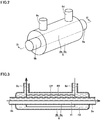
Fig. 2 is a perspective view schematically showing a configuration of an internal heat exchanger of the refrigeration cycle apparatus according to the first embodiment of the present invention. -
Fig. 3 is a cross-sectional view taken along line III-III inFig. 2 . -
Fig. 4 is a graph showing a relationship between a suction SH and a theoretical COP of R290 refrigerant and R32 refrigerant. -
Fig. 5 is a cross-sectional view schematically showing a flowing state of refrigerant in an internal heat exchanger in Comparative Example 1. -
Fig. 6 is a cross-sectional view schematically showing a flowing state of refrigerant in an internal heat exchanger in Comparative Example 2. -
Fig. 7 is a cross-sectional view schematically showing a flowing state of the refrigerant in the internal heat exchanger of the refrigeration cycle apparatus according to the first embodiment of the present invention. -
Fig. 8 is a partial cross-sectional view taken along line VIII-VIII inFig. 7 . -
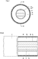
Fig. 9 is a cross-sectional view schematically showing a flowing state of refrigerant in an internal heat exchanger of a refrigeration cycle apparatus according to a second embodiment of the present invention. -
Fig. 10 is a partial cross-sectional view taken along line X-X inFig. 9 . - Embodiments of the present invention will be described hereinafter with reference to the drawings. In the following description, the same or corresponding portions are denoted by the same reference characters and description thereof will not be repeated in principle.
- A configuration of a
refrigeration cycle apparatus 1 according to a first embodiment of the present invention will be described with reference toFig. 1. Fig. 1 is a configuration diagram showing the refrigeration cycle apparatus according to the first embodiment of the present invention. The refrigeration cycle apparatus according to the first embodiment of the present invention is, for example, an air conditioner. As shown inFig. 1 ,refrigeration cycle apparatus 1 according to the first embodiment of the present invention includes arefrigerant circuit 2, acontroller 3, acondenser fan 10, anevaporator fan 11, and refrigerant. -
Refrigerant circuit 2 includes acompressor 4, acondenser 5, anexpansion valve 6, anevaporator 7, and aninternal heat exchanger 8.Compressor 4,condenser 5,expansion valve 6,evaporator 7, andinternal heat exchanger 8 are connected by apipe 9.Refrigerant circuit 2 is thus formed.Refrigerant circuit 2 is configured to circulate the refrigerant.Refrigerant circuit 2 is configured such that a refrigeration cycle is performed in which the refrigerant circulates in order ofcompressor 4,condenser 5,internal heat exchanger 8,expansion valve 6,evaporator 7, andinternal heat exchanger 8 while changing its phase. - The refrigerant flows in
refrigerant circuit 2 in order ofcompressor 4,condenser 5,internal heat exchanger 8,expansion valve 6,evaporator 7, andinternal heat exchanger 8. The refrigerant is such that a coefficient of performance of the refrigerant becomes higher as a suction superheat degree (suction SH) ofcompressor 4 becomes higher. The refrigerant is, for example, a hydrocarbon refrigerant (HC refrigerant). Specifically, the refrigerant is, for example, propane (R290), isobutane (R600a), pentane (R601), butane (R600), ethane (R170), or propylene (R1270). -
Controller 3 is configured to controlrefrigerant circuit 2.Controller 3 is configured to control instruments, devices and the like ofrefrigeration cycle apparatus 1 by performing computation, instruction and the like.Controller 3 is electrically connected tocompressor 4,expansion valve 6,condenser fan 10,evaporator fan 11 and the like and is configured to control operations thereof. -
Compressor 4 is configured to compress and discharge suctioned gaseous refrigerant.Compressor 4 is configured to be capacity-variable.Compressor 4 is configured such that a frequency is changed based on an instruction fromcontroller 3 to thereby adjust a rotation speed and change a capacity. Incompressor 4, refrigerator oil (lubricating oil) is used. The refrigerator oil is, for example, polyalkylene glycol (PAG)-based oil having an ether bond, polyol ester (POE)-based oil having an ester bond, or the like. -
Condenser 5 is configured to condense the refrigerant compressed bycompressor 4.Condenser 5 is connected tocompressor 4 andinternal heat exchanger 8.Condenser 5 includes a heat transfer tube through which the refrigerant flows.Condenser 5 is, for example, a fin-and-tube-type heat exchanger including a plurality of fins and a circular or flat heat transfer tube passing through the plurality of fins. -
Expansion valve 6 is configured to expand and decompress the liquid refrigerant condensed bycondenser 5. The liquid refrigerant condensed bycondenser 5 is expanded and decompressed byexpansion valve 6, and thus, the refrigerant enters a gas-liquid two-phase state at an outlet ofexpansion valve 6.Expansion valve 6 is connected tocondenser 5 andevaporator 7.Expansion valve 6 is, for example, an electric expansion valve configured to adjust a flow rate of the refrigerant based on an instruction fromcontroller 3. An amount of the refrigerant flowing throughexpansion valve 6 is adjusted by adjusting a degree of opening ofexpansion valve 6. -
Evaporator 7 is configured to evaporate the refrigerant decompressed byexpansion valve 6.Evaporator 7 is connected toexpansion valve 6 andinternal heat exchanger 8.Evaporator 7 includes a heat transfer tube through which the refrigerant flows.Evaporator 7 is, for example, a fin-and-tube-type heat exchanger including a plurality of fins and a circular or flat heat transfer tube passing through the plurality of fins. -
Internal heat exchanger 8 is configured to cause heat exchange between the refrigerant on the outlet side ofcondenser 5 and the refrigerant on the outlet side ofevaporator 7. Ininternal heat exchanger 8, heat exchange is performed between the refrigerant condensed bycondenser 5 and the refrigerant evaporated byevaporator 7. -
Pipe 9 connectscompressor 4,condenser 5,expansion valve 6,evaporator 7, andinternal heat exchanger 8.Pipe 9 forms a gas-side refrigerant path and a liquid-side refrigerant path.Pipe 9 includes afirst pipe portion 9a, asecond pipe portion 9b, athird pipe portion 9c, and afourth pipe portion 9d.First pipe portion 9a is connected tocondenser 5 andinternal heat exchanger 8.Second pipe portion 9b is connected tointernal heat exchanger 8 andexpansion valve 6.Third pipe portion 9c is connected toevaporator 7 andinternal heat exchanger 8.Fourth pipe portion 9d is connected tointernal heat exchanger 8 andcompressor 4. - In cooling,
condenser fan 10 is provided in a not-shown outdoor unit.Condenser fan 10 is configured to forcibly deliver outdoor air tocondenser 5.Condenser fan 10 is attached tocondenser 5 and is configured to supply air as a heat exchange fluid tocondenser 5.Condenser fan 10 is configured such that a rotation speed ofcondenser fan 10 is adjusted based on an instruction fromcontroller 3 to thereby adjust an amount of air flowing aroundcondenser 5 and adjust an amount of heat exchange between the air and the refrigerant. -
Evaporator fan 11 is provided in a not-shown indoor unit.Evaporator fan 11 is configured to forcibly deliver indoor air toevaporator 7.Evaporator fan 11 is attached toevaporator 7 and is configured to supply air as a heat exchange fluid toevaporator 7.Evaporator fan 11 is configured such that a rotation speed ofevaporator fan 11 is adjusted based on an instruction fromcontroller 3 to thereby adjust an amount of air flowing aroundevaporator 7 and adjust an amount of heat exchange between the air and the refrigerant. - A configuration of
internal heat exchanger 8 will be described in detail with reference toFigs. 1 to 3 . - As shown in
Figs. 2 and 3 ,internal heat exchanger 8 is a double-pipe-type heat exchanger.Internal heat exchanger 8 includes aninner pipe 8a and anouter pipe 8b.Inner pipe 8a has a pipe shape.Outer pipe 8b has a pipe shape.Inner pipe 8a is inserted inouter pipe 8b. That is,inner pipe 8a is arranged withinouter pipe 8b. A gap GP is provided between an outer circumferential surface ofinner pipe 8a and an inner circumferential surface ofouter pipe 8b. Gap GP may have an uniform dimension over an entire circumference in an outer circumferential direction ofinner pipe 8a. - As shown in
Figs. 1 to 3 ,inner pipe 8a is connected tocondenser 5 andexpansion valve 6.Inner pipe 8a is connected tocondenser 5 withfirst pipe portion 9a being interposed, and is connected toexpansion valve 6 withsecond pipe portion 9b being interposed.Inner pipe 8a is configured such that the high-pressure-side refrigerant flows therethrough.Outer pipe 8b is connected toevaporator 7 andcompressor 4.Outer pipe 8b is connected toevaporator 7 withthird pipe portion 9c being interposed, and is connected tocompressor 4 withfourth pipe portion 9d being interposed.Outer pipe 8b is configured such that the low-pressure-side refrigerant flows therethrough. -
Internal heat exchanger 8 is configured to cause heat exchange between the refrigerant flowing insideinner pipe 8a in a direction fromcondenser 5 towardexpansion valve 6 and the refrigerant flowing insideouter pipe 8b and outsideinner pipe 8a in a direction fromevaporator 7 towardcompressor 4.Internal heat exchanger 8 is configured to cause heat exchange, via a wall surface ofinner pipe 8a, between the refrigerant flowing insideinner pipe 8a and the refrigerant flowing insideouter pipe 8b and outsideinner pipe 8a.Internal heat exchanger 8 is configured to cause heat exchange, via the wall surface ofinner pipe 8a, between the refrigerant flowing insideinner pipe 8a and the refrigerant flowing through gap GP. - In
internal heat exchanger 8, the refrigerant flowing insideouter pipe 8b and outsideinner pipe 8a is entirely gas. The refrigerant flowing through gap GP is entirely gas. The refrigerant flowing insideouter pipe 8b and outsideinner pipe 8a is entirely in a dry state. - Next, an operation of
refrigeration cycle apparatus 1 will be described with reference toFigs. 1 to 3 . During a refrigeration cycle operation, the gaseous refrigerant compressed bycompressor 4 is discharged fromcompressor 4 and delivered tocondenser 5 throughpipe 9 serving as the gas-side refrigerant path. Incondenser 5, heat is released from the refrigerant flowing through the heat transfer tube to the air, and the refrigerant is thereby condensed. Thereafter, the refrigerant is delivered tointernal heat exchanger 8 throughfirst pipe portion 9a serving as the liquid-side refrigerant path. The refrigerant delivered tointernal heat exchanger 8 throughfirst pipe portion 9a flows throughinner pipe 8a ofinternal heat exchanger 8, and then, is delivered toexpansion valve 6 throughsecond pipe portion 9b. - In
expansion valve 6, the liquid refrigerant is decompressed to the refrigerant in a gas-liquid two-phase state. The refrigerant decompressed byexpansion valve 6 is delivered toevaporator 7 throughpipe 9 serving as the liquid-side refrigerant path. Thereafter, the refrigerant takes in heat from the air and evaporates inevaporator 7, and then, is delivered tointernal heat exchanger 8 throughthird pipe portion 9c serving as the gas-side refrigerant path. The refrigerant delivered tointernal heat exchanger 8 throughthird pipe portion 9c flows throughouter pipe 8b ofinternal heat exchanger 8, and then, returns tocompressor 4 throughfourth pipe portion 9d. - In
internal heat exchanger 8, heat exchange is performed between the refrigerant on the outlet side of condenser 5 (high-pressure-side refrigerant) flowing throughinner pipe 8a and the refrigerant on the outlet side of evaporator 7 (low-pressure-side refrigerant) flowing throughouter pipe 8b. Since a degree of dryness of the refrigerant at the outlet ofevaporator 7 can be reduced byinternal heat exchanger 8, the heat transfer performance ofevaporator 7 is improved. As a result, a coefficient of performance (COP) ofrefrigeration cycle apparatus 1 is improved. - Next, functions and effects of
refrigeration cycle apparatus 1 according to the first embodiment of the present invention will be described in comparison with Comparative Example 1 and Comparative Example 2. - Here, in
refrigeration cycle apparatus 1 according to the first embodiment of the present invention, the R290 refrigerant is used as one example of the refrigerant. Comparative Example 1 is different fromrefrigeration cycle apparatus 1 according to the first embodiment of the present invention in that the refrigerant is R32. The R32 refrigerant has a global warming potential (GWP) greater than that of the R290 refrigerant. In addition, Comparative Example 1 is different from the refrigeration cycle apparatus according to the first embodiment of the present invention in that the low-pressure-side refrigerant flows throughinner pipe 8a and the high-pressure-side refrigerant flows throughouter pipe 8b ininternal heat exchanger 8. That is, in Comparative Example 1,inner pipe 8a is connected toevaporator 7 andcompressor 4 andouter pipe 8b is connected tocondenser 5 andexpansion valve 6 ininternal heat exchanger 8. -
Fig. 4 is a graph showing a relationship between a theoretical coefficient of performance (hereinafter, referred to as "theoretical COP") and a suction superheat degree (suction SH) ofcompressor 4 when each of the R290 refrigerant and the R32 refrigerant is used as the refrigerant forrefrigerant circuit 2. The coefficient of performance (COP) is a ratio of consumed electric power to a capacity ofrefrigeration cycle apparatus 1. - Referring to
Fig. 4 , the theoretical COP of the R32 refrigerant decreases as the suction superheat degree (suction SH) ofcompressor 4 increases. In contrast, the theoretical COP of the R290 refrigerant increases as the suction superheat degree (SH) ofcompressor 4 increases. This is because the R290 refrigerant and the R32 refrigerant are different in properties. That is, as the suction superheat degree (suction SH) ofcompressor 4 increases, the coefficient of performance of the R290 refrigerant becomes superior to that of the R32 refrigerant. - Due to the properties of the R32 refrigerant, the coefficient of performance of the R32 refrigerant is higher when the suction superheat degree (suction SH) of
compressor 4 is zero than when the suction superheat degree (suction SH) ofcompressor 4 is higher than zero. Therefore, in order to increase the coefficient of performance, the low-pressure-side refrigerant is brought into a wet state ininternal heat exchanger 8 so as to prevent the suction superheat degree (suction SH) ofcompressor 4 from becoming higher than zero. -
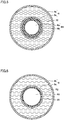
Fig. 5 is a cross-sectional view showing a flowing state of the refrigerant ininternal heat exchanger 8 in Comparative Example 1. Referring toFig. 5 , ininternal heat exchanger 8 in Comparative Example 1, refrigerant R1 flowing throughinner pipe 8a is low-pressure-side refrigerant, and refrigerant R2 flowing throughouter pipe 8b is high-pressure-side refrigerant. Low-pressure-side refrigerant R1 flowing throughinner pipe 8a is in a gas-liquid two-phase state. Low-pressure-side refrigerant R1 flowing throughinner pipe 8a forms an annular flow. That is, as for the low-pressure-side refrigerant flowing throughinner pipe 8a, gas refrigerant Ra flows through a central portion ofinner pipe 8a, and liquid refrigerant Rb flows through an outer portion along the wall surface ofinner pipe 8a. Since liquid refrigerant Rb comes into contact with the wall surface ofinner pipe 8a serving as a heat transfer surface, the heat transfer performance increases. However, since the refrigerant in Comparative Example 1 is the R32 refrigerant, the global warming potential of the refrigerant is greater than that of the R290 refrigerant. Therefore, in Comparative Example 1, the global warming potential of the refrigerant cannot be reduced. -
Fig. 6 is a cross-sectional view showing a flowing state of the refrigerant ininternal heat exchanger 8 in Comparative Example 2. Referring toFig. 6 , ininternal heat exchanger 8 in Comparative Example 2, refrigerant R1 flowing throughinner pipe 8a is low-pressure-side refrigerant, and refrigerant R2 flowing throughouter pipe 8b is high-pressure-side refrigerant. In this respect, Comparative Example 2 is different fromrefrigeration cycle apparatus 1 according to the first embodiment of the present invention. The refrigerant in Comparative Example 2 is propane (R290). - When the superheat degree of the refrigerant at the outlet of
evaporator 7 is zero (SH=0), the performance ofevaporator 7 is theoretically high. However, due to properties of the propane (R290) refrigerant, the coefficient of performance becomes superior as the suction superheat degree (suction SH) ofcompressor 4 becomes higher. Therefore, in order to increase the suction superheat degree (suction SH) ofcompressor 4 while keeping the superheat degree of the refrigerant at the outlet ofevaporator 7 zero (SH=0), the superheat degree of the refrigerant at the low-pressure-side inlet ofinternal heat exchanger 8 may only be zero. - When
refrigeration cycle apparatus 1 including propane (R290) used as the refrigerant is operated such that the coefficient of performance ofrefrigeration cycle apparatus 1 becomes higher, the superheat degree of the refrigerant at the outlet ofevaporator 7 becomes near zero. In this case, the superheat degree at the low-pressure-side outlet ofinternal heat exchanger 8, i.e., at the inlet ofcompressor 4 becomes higher than or equal to zero. In addition, the refrigerant at the low-pressure-side inlet ofinternal heat exchanger 8 is gas. In this case, refrigerant R1 flowing throughinner pipe 8a ofinternal heat exchanger 8 does not include liquid refrigerant, and thus,refrigerator oil 20 is likely to precipitate on an inner surface of the wall surface ofinner pipe 8a. Whenrefrigerator oil 20 is precipitated on the wall surface ofinner pipe 8a ofinternal heat exchanger 8,refrigerator oil 20 precipitated on the wall surface ofinner pipe 8a ofinternal heat exchanger 8 serves as a thermal resistance, and thus, the heat transfer performance ofinternal heat exchanger 8 decreases. -
Figs. 7 and 8 are cross-sectional views showing a flowing state of the refrigerant ininternal heat exchanger 8 ofrefrigeration cycle apparatus 1 according to the first embodiment of the present invention. Referring toFigs. 7 and 8 , ininternal heat exchanger 8 ofrefrigeration cycle apparatus 1 according to the first embodiment of the present invention, refrigerant R1 flowing throughinner pipe 8a is high-pressure-side refrigerant, and refrigerant R2 flowing throughouter pipe 8b is low-pressure-side refrigerant. - The wall surface of
inner pipe 8a serves as a heat transfer surface where heat exchange is performed between high-pressure-side refrigerant R1 flowing throughinner pipe 8a and low-pressure-side refrigerant R2 flowing throughouter pipe 8b ininternal heat exchanger 8. In addition to the wall surface ofinner pipe 8a serving as the heat transfer surface where heat exchange is performed between the low-pressure-side refrigerant flowing throughouter pipe 8b and the high-pressure-side refrigerant flowing throughinner pipe 8a, there exists a wall surface ofouter pipe 8b serving as a heat transfer surface where heat exchange is performed between the low-pressure-side refrigerant flowing throughouter pipe 8b and the air outsideouter pipe 8b. Therefore, an area of the wall surface on whichrefrigerator oil 20 is precipitated is larger inrefrigeration cycle apparatus 1 according to the first embodiment of the present invention than in Comparative Example 2. Thus, an oil amount of the refrigerator oil precipitated on the wall surface ofinner pipe 8a serving as the heat transfer surface decreases. Therefore, the refrigerator oil precipitated on the wall surface ofinner pipe 8a serves as a thermal resistance, and thus, a reduction in heat transfer performance ofinternal heat exchanger 8 can be suppressed. - That is, in
refrigeration cycle apparatus 1 according to the first embodiment of the present invention, the propane (R290) refrigerant is used, and the high-pressure-side refrigerant flows throughinner pipe 8a ofinternal heat exchanger 8 and the low-pressure-side refrigerant flows throughouter pipe 8b ofinternal heat exchanger 8. Furthermore, the refrigerant at the low-pressure-side inlet ofinternal heat exchanger 8 is in a dry state. That is, the superheat degree of the refrigerant at the low-pressure-side inlet ofinternal heat exchanger 8 is zero. Therefore, a reduction in heat transfer performance caused by precipitation of the refrigerator oil ininternal heat exchanger 8 is suppressed. Thus, the operation with a high coefficient of performance can be achieved inrefrigeration cycle apparatus 1. - In
refrigeration cycle apparatus 1 according to the first embodiment of the present invention, the refrigerant is a hydrocarbon refrigerant (HC refrigerant). Therefore, the refrigerant having a small global warming potential (GWP) can be used. In addition, the refrigerant flowing insideouter pipe 8b and outsideinner pipe 8a ofinternal heat exchanger 8 is entirely gas. Therefore, the superheat degree of the refrigerant at the inlet ofcompressor 4 can be increased, as compared with the case in which the refrigerant flowing insideouter pipe 8b and outsideinner pipe 8a ofinternal heat exchanger 8 includes liquid refrigerant. Thus, the coefficient of performance (COP) ofrefrigeration cycle apparatus 1 can be increased. Furthermore, the superheat degree of the refrigerant at the outlet ofouter pipe 8b ofinternal heat exchanger 8 can be increased, as compared with the case in which the refrigerant flowing insideouter pipe 8b and outsideinner pipe 8a ofinternal heat exchanger 8 includes liquid refrigerant. Therefore, the amount of the refrigerant ininternal heat exchanger 8 can be reduced. - In
refrigeration cycle apparatus 1 according to the first embodiment of the present invention, the refrigerant is an HC refrigerant. Therefore, the global warming potential (GWP) of the refrigerant can be reduced. - In
refrigeration cycle apparatus 1 according to the first embodiment of the present invention,expansion valve 6 is an electric expansion valve configured to adjust a flow rate of the refrigerant. Therefore, the flow rate of the refrigerant can be adjusted by the electric expansion valve. -
Refrigeration cycle apparatus 1 according to a second embodiment of the present invention has the same configuration, operation and effect as those of above-describedrefrigeration cycle apparatus 1 according to the first embodiment of the present invention, unless otherwise stated. - Referring to
Figs. 9 and 10 ,refrigeration cycle apparatus 1 according to the second embodiment of the present invention is different in a configuration ofouter pipe 8b ofinternal heat exchanger 8 fromrefrigeration cycle apparatus 1 according to the first embodiment of the present invention. - In
refrigeration cycle apparatus 1 according to the second embodiment of the present invention, agroove 30 is provided in an inner surface ofouter pipe 8b ofinternal heat exchanger 8.Groove 30 may be provided over an entire circumference of the inner surface ofouter pipe 8b ofinternal heat exchanger 8.Groove 30 may be configured to be serrated.Inner pipe 8a ofinternal heat exchanger 8 is not provided withgroove 30. That is, no groove is provided in an inner surface and an outer surface ofinner pipe 8a ofinternal heat exchanger 8. - Since only
outer pipe 8b ofinternal heat exchanger 8 is provided withgroove 30,refrigerator oil 20 is likely to precipitate ingroove 30, which is a portion that does not contribute to heat transfer between the refrigerant flowing throughinner pipe 8a and the refrigerant flowing throughouter pipe 8b ininternal heat exchanger 8. As a result, a reduction in heat transfer performance caused by the refrigerator oil precipitated on the wall surface ofinner pipe 8a can be suppressed, as compared with the first embodiment. - In
refrigeration cycle apparatus 1 according to the present embodiment,groove 30 is provided in the inner surface ofouter pipe 8b ofinternal heat exchanger 8. Sincegroove 30 results in an increase in heat transfer area ofouter pipe 8b,refrigerator oil 20 is likely to precipitate ingroove 30. Therefore, a reduction in heat transfer performance caused by the refrigerator oil precipitated on the wall surface ofinner pipe 8a can be suppressed. - In
refrigeration cycle apparatus 1 according to the present embodiment,groove 30 is configured to be serrated. Therefore, the refrigerator oil is likely to precipitate on the bottom of the serrated configuration. - It should be understood that the embodiments disclosed herein are illustrative and non-restrictive in every respect. The scope of the present invention is defined by the terms of the claims, rather than the description above, and is intended to include any modifications within the scope and meaning equivalent to the terms of the claims.
- 1 refrigeration cycle apparatus; 2 refrigerant circuit; 3 controller; 4 compressor; 5 condenser; 6 expansion valve; 7 evaporator; 8 internal heat exchanger; 8a inner pipe; 8b outer pipe; 9 pipe; 10 condenser fan; 11 evaporator fan; 20 refrigerator oil; 30 groove.
Claims (5)
- A refrigeration cycle apparatus comprising:a refrigerant circuit comprising a compressor, a condenser, an expansion valve, an evaporator, and an internal heat exchanger; andrefrigerant flowing in the refrigerant circuit in order of the compressor, the condenser, the internal heat exchanger, the expansion valve, the evaporator, and the internal heat exchanger,the refrigerant being a hydrocarbon refrigerant,the internal heat exchanger comprising:an inner pipe connected to the condenser and the expansion valve; andan outer pipe connected to the evaporator and the compressor, the inner pipe being inserted in the outer pipe,the internal heat exchanger being configured to cause heat exchange betweenthe refrigerant flowing inside the inner pipe in a direction from the condenser toward the expansion valve, andthe refrigerant flowing inside the outer pipe and outside the inner pipe in a direction from the evaporator toward the compressor,the refrigerant flowing inside the outer pipe and outside the inner pipe being entirely gas.
- The refrigeration cycle apparatus according to claim 1, wherein
a groove is provided in an inner surface of the outer pipe. - The refrigeration cycle apparatus according to claim 2, wherein
the groove is configured to be serrated. - The refrigeration cycle apparatus according to any one of claims 1 to 3, wherein
the refrigerant is an HC refrigerant. - The refrigeration cycle apparatus according to any one of claims 1 to 4, wherein
the expansion valve is an electric expansion valve configured to adjust a flow rate of the refrigerant.
Applications Claiming Priority (1)
| Application Number | Priority Date | Filing Date | Title |
|---|---|---|---|
| PCT/JP2019/000356 WO2020144764A1 (en) | 2019-01-09 | 2019-01-09 | Refrigeration cycle device |
Publications (3)
| Publication Number | Publication Date |
|---|---|
| EP3910262A1 true EP3910262A1 (en) | 2021-11-17 |
| EP3910262A4 EP3910262A4 (en) | 2021-12-29 |
| EP3910262B1 EP3910262B1 (en) | 2024-08-21 |
Family
ID=71521528
Family Applications (1)
| Application Number | Title | Priority Date | Filing Date |
|---|---|---|---|
| EP19908451.8A Active EP3910262B1 (en) | 2019-01-09 | 2019-01-09 | Refrigeration cycle device |
Country Status (4)
| Country | Link |
|---|---|
| EP (1) | EP3910262B1 (en) |
| JP (1) | JP7460550B2 (en) |
| CN (1) | CN113227672A (en) |
| WO (1) | WO2020144764A1 (en) |
Families Citing this family (4)
| Publication number | Priority date | Publication date | Assignee | Title |
|---|---|---|---|---|
| CN118541576A (en) * | 2022-01-21 | 2024-08-23 | 三菱电机株式会社 | Air conditioning unit |
| TWI839240B (en) * | 2023-05-31 | 2024-04-11 | 台灣奧利安產業股份有限公司 | Fluid heat exchange system |
| TWI841406B (en) * | 2023-05-31 | 2024-05-01 | 台灣奧利安產業股份有限公司 | Atmospheric heat exchange system |
| WO2025182020A1 (en) * | 2024-02-29 | 2025-09-04 | 三菱電機株式会社 | Refrigeration cycle device |
Family Cites Families (17)
| Publication number | Priority date | Publication date | Assignee | Title |
|---|---|---|---|---|
| JP4006861B2 (en) * | 1998-12-09 | 2007-11-14 | 株式会社デンソー | Integrated heat exchanger |
| DE19944951B4 (en) * | 1999-09-20 | 2010-06-10 | Behr Gmbh & Co. Kg | Air conditioning with internal heat exchanger |
| JP2001280864A (en) | 2000-03-30 | 2001-10-10 | Hitachi Ltd | Heat exchanger and method of manufacturing the same |
| JP2003314927A (en) * | 2002-04-18 | 2003-11-06 | Matsushita Electric Ind Co Ltd | Heat exchanger and refrigeration cycle device using the heat exchanger |
| JP2005009833A (en) * | 2003-06-20 | 2005-01-13 | Hitachi Cable Ltd | Double tube heat exchanger |
| JP2004012127A (en) * | 2003-10-02 | 2004-01-15 | Mitsubishi Electric Corp | Refrigerator using flammable refrigerant |
| KR200420568Y1 (en) * | 2006-04-20 | 2006-07-04 | 주식회사 두원공조 | Low pressure side outlet structure of internal heat exchanger |
| JP2008164245A (en) * | 2006-12-28 | 2008-07-17 | Kobelco & Materials Copper Tube Inc | Heat exchanger |
| JP4884365B2 (en) | 2007-12-28 | 2012-02-29 | 三菱電機株式会社 | Refrigeration air conditioner, refrigeration air conditioner outdoor unit, and refrigeration air conditioner control device |
| CN101363697A (en) * | 2008-09-28 | 2009-02-11 | 湖南晟通科技集团有限公司 | High-efficiency heat exchange tube with minuteness passage |
| JP2010127498A (en) * | 2008-11-26 | 2010-06-10 | Nippon Soken Inc | Refrigerating cycle device |
| JP2010261680A (en) * | 2009-05-11 | 2010-11-18 | Sanden Corp | Double-pipe heat exchanger |
| JP5504050B2 (en) * | 2009-06-30 | 2014-05-28 | 株式会社ケーヒン・サーマル・テクノロジー | Double tube heat exchanger and method for manufacturing the same |
| JP5333041B2 (en) * | 2009-08-21 | 2013-11-06 | ダイキン工業株式会社 | Heat exchanger and refrigeration apparatus provided with the same |
| DE102013201313A1 (en) * | 2012-02-23 | 2013-08-29 | Ford Global Technologies, Llc | Internal heat exchanger for air conditioner of motor vehicle, has high pressure side and low pressure side, where heat exchanger is formed in spatial-bodily manner so that pulsations of passed through refrigerants are predominantly damped |
| JP2014105890A (en) * | 2012-11-26 | 2014-06-09 | Panasonic Corp | Refrigeration cycle device and hot-water generating device including the same |
| JP5717903B2 (en) * | 2014-05-28 | 2015-05-13 | 三菱電機株式会社 | Refrigeration air conditioner |
-
2019
- 2019-01-09 EP EP19908451.8A patent/EP3910262B1/en active Active
- 2019-01-09 WO PCT/JP2019/000356 patent/WO2020144764A1/en not_active Ceased
- 2019-01-09 CN CN201980079923.1A patent/CN113227672A/en active Pending
- 2019-01-09 JP JP2020565068A patent/JP7460550B2/en active Active
Also Published As
| Publication number | Publication date |
|---|---|
| WO2020144764A1 (en) | 2020-07-16 |
| EP3910262B1 (en) | 2024-08-21 |
| EP3910262A4 (en) | 2021-12-29 |
| JP7460550B2 (en) | 2024-04-02 |
| CN113227672A (en) | 2021-08-06 |
| JPWO2020144764A1 (en) | 2021-09-30 |
Similar Documents
| Publication | Publication Date | Title |
|---|---|---|
| JP6847299B2 (en) | Refrigeration cycle equipment | |
| EP3910262B1 (en) | Refrigeration cycle device | |
| US10101060B2 (en) | Cooling system | |
| JP6482655B2 (en) | Refrigeration cycle equipment | |
| US20220214085A1 (en) | Evaporator and refrigeration cycle apparatus including the same | |
| EP3217115B1 (en) | Air conditioning apparatus | |
| EP3862651B1 (en) | Refrigeration cycle device | |
| KR101901540B1 (en) | Air conditioning device | |
| JP2017145975A (en) | Refrigeration cycle apparatus, refrigeration cycle apparatus manufacturing method, refrigeration cycle apparatus drop-in method, and refrigeration cycle apparatus replacement method | |
| EP3483523A1 (en) | Refrigeration cycle apparatus and air-conditioning apparatus provided with same | |
| US11371758B2 (en) | Refrigeration cycle apparatus | |
| JP6779383B2 (en) | Refrigerator with condenser and condenser | |
| JP2011047552A (en) | Refrigerating cycle device and air conditioner | |
| EP4184105A1 (en) | Heat exchanger | |
| JP6758506B2 (en) | Air conditioner | |
| JP4078786B2 (en) | Refrigeration and air conditioning cycle equipment | |
| CN112012929A (en) | Compressor Lubricant Quality Management | |
| JP7118247B2 (en) | air conditioner | |
| EP4467893A1 (en) | Air conditioner | |
| CN105264304A (en) | Air conditioner | |
| EP3770535A1 (en) | Heat exchanger, refrigeration cycle device, and air conditioning device | |
| KR20220170108A (en) | Device including a refrigerant cycle | |
| JP2002195700A (en) | Refrigeration cycle device | |
| JPH11142006A (en) | Refrigerant circulation system |
Legal Events
| Date | Code | Title | Description |
|---|---|---|---|
| STAA | Information on the status of an ep patent application or granted ep patent |
Free format text: STATUS: THE INTERNATIONAL PUBLICATION HAS BEEN MADE |
|
| PUAI | Public reference made under article 153(3) epc to a published international application that has entered the european phase |
Free format text: ORIGINAL CODE: 0009012 |
|
| STAA | Information on the status of an ep patent application or granted ep patent |
Free format text: STATUS: REQUEST FOR EXAMINATION WAS MADE |
|
| 17P | Request for examination filed |
Effective date: 20210503 |
|
| AK | Designated contracting states |
Kind code of ref document: A1 Designated state(s): AL AT BE BG CH CY CZ DE DK EE ES FI FR GB GR HR HU IE IS IT LI LT LU LV MC MK MT NL NO PL PT RO RS SE SI SK SM TR |
|
| A4 | Supplementary search report drawn up and despatched |
Effective date: 20211125 |
|
| RIC1 | Information provided on ipc code assigned before grant |
Ipc: F28F 13/00 20060101ALI20211119BHEP Ipc: F25B 40/06 20060101ALI20211119BHEP Ipc: F25B 40/02 20060101ALI20211119BHEP Ipc: F28D 7/10 20060101ALI20211119BHEP Ipc: F25B 1/00 20060101AFI20211119BHEP |
|
| DAV | Request for validation of the european patent (deleted) | ||
| DAX | Request for extension of the european patent (deleted) | ||
| STAA | Information on the status of an ep patent application or granted ep patent |
Free format text: STATUS: EXAMINATION IS IN PROGRESS |
|
| 17Q | First examination report despatched |
Effective date: 20230323 |
|
| GRAP | Despatch of communication of intention to grant a patent |
Free format text: ORIGINAL CODE: EPIDOSNIGR1 |
|
| STAA | Information on the status of an ep patent application or granted ep patent |
Free format text: STATUS: GRANT OF PATENT IS INTENDED |
|
| RIC1 | Information provided on ipc code assigned before grant |
Ipc: F28F 13/18 20060101ALI20240306BHEP Ipc: F28F 1/40 20060101ALI20240306BHEP Ipc: F28D 21/00 20060101ALI20240306BHEP Ipc: F28F 13/00 20060101ALI20240306BHEP Ipc: F25B 40/06 20060101ALI20240306BHEP Ipc: F25B 40/02 20060101ALI20240306BHEP Ipc: F28D 7/10 20060101ALI20240306BHEP Ipc: F25B 1/00 20060101AFI20240306BHEP |
|
| INTG | Intention to grant announced |
Effective date: 20240403 |
|
| GRAS | Grant fee paid |
Free format text: ORIGINAL CODE: EPIDOSNIGR3 |
|
| GRAA | (expected) grant |
Free format text: ORIGINAL CODE: 0009210 |
|
| STAA | Information on the status of an ep patent application or granted ep patent |
Free format text: STATUS: THE PATENT HAS BEEN GRANTED |
|
| AK | Designated contracting states |
Kind code of ref document: B1 Designated state(s): AL AT BE BG CH CY CZ DE DK EE ES FI FR GB GR HR HU IE IS IT LI LT LU LV MC MK MT NL NO PL PT RO RS SE SI SK SM TR |
|
| REG | Reference to a national code |
Ref country code: GB Ref legal event code: FG4D |
|
| REG | Reference to a national code |
Ref country code: CH Ref legal event code: EP |
|
| REG | Reference to a national code |
Ref country code: IE Ref legal event code: FG4D |
|
| REG | Reference to a national code |
Ref country code: DE Ref legal event code: R096 Ref document number: 602019057667 Country of ref document: DE |
|
| REG | Reference to a national code |
Ref country code: LT Ref legal event code: MG9D |
|
| REG | Reference to a national code |
Ref country code: NL Ref legal event code: MP Effective date: 20240821 |
|
| PG25 | Lapsed in a contracting state [announced via postgrant information from national office to epo] |
Ref country code: NO Free format text: LAPSE BECAUSE OF FAILURE TO SUBMIT A TRANSLATION OF THE DESCRIPTION OR TO PAY THE FEE WITHIN THE PRESCRIBED TIME-LIMIT Effective date: 20241121 |
|
| REG | Reference to a national code |
Ref country code: AT Ref legal event code: MK05 Ref document number: 1715835 Country of ref document: AT Kind code of ref document: T Effective date: 20240821 |
|
| PG25 | Lapsed in a contracting state [announced via postgrant information from national office to epo] |
Ref country code: NL Free format text: LAPSE BECAUSE OF FAILURE TO SUBMIT A TRANSLATION OF THE DESCRIPTION OR TO PAY THE FEE WITHIN THE PRESCRIBED TIME-LIMIT Effective date: 20240821 Ref country code: PT Free format text: LAPSE BECAUSE OF FAILURE TO SUBMIT A TRANSLATION OF THE DESCRIPTION OR TO PAY THE FEE WITHIN THE PRESCRIBED TIME-LIMIT Effective date: 20241223 Ref country code: FI Free format text: LAPSE BECAUSE OF FAILURE TO SUBMIT A TRANSLATION OF THE DESCRIPTION OR TO PAY THE FEE WITHIN THE PRESCRIBED TIME-LIMIT Effective date: 20240821 Ref country code: GR Free format text: LAPSE BECAUSE OF FAILURE TO SUBMIT A TRANSLATION OF THE DESCRIPTION OR TO PAY THE FEE WITHIN THE PRESCRIBED TIME-LIMIT Effective date: 20241122 Ref country code: PL Free format text: LAPSE BECAUSE OF FAILURE TO SUBMIT A TRANSLATION OF THE DESCRIPTION OR TO PAY THE FEE WITHIN THE PRESCRIBED TIME-LIMIT Effective date: 20240821 |
|
| PGFP | Annual fee paid to national office [announced via postgrant information from national office to epo] |
Ref country code: GB Payment date: 20241128 Year of fee payment: 7 |
|
| PG25 | Lapsed in a contracting state [announced via postgrant information from national office to epo] |
Ref country code: BG Free format text: LAPSE BECAUSE OF FAILURE TO SUBMIT A TRANSLATION OF THE DESCRIPTION OR TO PAY THE FEE WITHIN THE PRESCRIBED TIME-LIMIT Effective date: 20240821 |
|
| PG25 | Lapsed in a contracting state [announced via postgrant information from national office to epo] |
Ref country code: LV Free format text: LAPSE BECAUSE OF FAILURE TO SUBMIT A TRANSLATION OF THE DESCRIPTION OR TO PAY THE FEE WITHIN THE PRESCRIBED TIME-LIMIT Effective date: 20240821 |
|
| PG25 | Lapsed in a contracting state [announced via postgrant information from national office to epo] |
Ref country code: AT Free format text: LAPSE BECAUSE OF FAILURE TO SUBMIT A TRANSLATION OF THE DESCRIPTION OR TO PAY THE FEE WITHIN THE PRESCRIBED TIME-LIMIT Effective date: 20240821 Ref country code: IS Free format text: LAPSE BECAUSE OF FAILURE TO SUBMIT A TRANSLATION OF THE DESCRIPTION OR TO PAY THE FEE WITHIN THE PRESCRIBED TIME-LIMIT Effective date: 20241221 |
|
| PG25 | Lapsed in a contracting state [announced via postgrant information from national office to epo] |
Ref country code: HR Free format text: LAPSE BECAUSE OF FAILURE TO SUBMIT A TRANSLATION OF THE DESCRIPTION OR TO PAY THE FEE WITHIN THE PRESCRIBED TIME-LIMIT Effective date: 20240821 |
|
| PG25 | Lapsed in a contracting state [announced via postgrant information from national office to epo] |
Ref country code: ES Free format text: LAPSE BECAUSE OF FAILURE TO SUBMIT A TRANSLATION OF THE DESCRIPTION OR TO PAY THE FEE WITHIN THE PRESCRIBED TIME-LIMIT Effective date: 20240821 Ref country code: RS Free format text: LAPSE BECAUSE OF FAILURE TO SUBMIT A TRANSLATION OF THE DESCRIPTION OR TO PAY THE FEE WITHIN THE PRESCRIBED TIME-LIMIT Effective date: 20241121 |
|
| PG25 | Lapsed in a contracting state [announced via postgrant information from national office to epo] |
Ref country code: RS Free format text: LAPSE BECAUSE OF FAILURE TO SUBMIT A TRANSLATION OF THE DESCRIPTION OR TO PAY THE FEE WITHIN THE PRESCRIBED TIME-LIMIT Effective date: 20241121 Ref country code: PT Free format text: LAPSE BECAUSE OF FAILURE TO SUBMIT A TRANSLATION OF THE DESCRIPTION OR TO PAY THE FEE WITHIN THE PRESCRIBED TIME-LIMIT Effective date: 20241223 Ref country code: PL Free format text: LAPSE BECAUSE OF FAILURE TO SUBMIT A TRANSLATION OF THE DESCRIPTION OR TO PAY THE FEE WITHIN THE PRESCRIBED TIME-LIMIT Effective date: 20240821 Ref country code: NO Free format text: LAPSE BECAUSE OF FAILURE TO SUBMIT A TRANSLATION OF THE DESCRIPTION OR TO PAY THE FEE WITHIN THE PRESCRIBED TIME-LIMIT Effective date: 20241121 Ref country code: NL Free format text: LAPSE BECAUSE OF FAILURE TO SUBMIT A TRANSLATION OF THE DESCRIPTION OR TO PAY THE FEE WITHIN THE PRESCRIBED TIME-LIMIT Effective date: 20240821 Ref country code: LV Free format text: LAPSE BECAUSE OF FAILURE TO SUBMIT A TRANSLATION OF THE DESCRIPTION OR TO PAY THE FEE WITHIN THE PRESCRIBED TIME-LIMIT Effective date: 20240821 Ref country code: IS Free format text: LAPSE BECAUSE OF FAILURE TO SUBMIT A TRANSLATION OF THE DESCRIPTION OR TO PAY THE FEE WITHIN THE PRESCRIBED TIME-LIMIT Effective date: 20241221 Ref country code: HR Free format text: LAPSE BECAUSE OF FAILURE TO SUBMIT A TRANSLATION OF THE DESCRIPTION OR TO PAY THE FEE WITHIN THE PRESCRIBED TIME-LIMIT Effective date: 20240821 Ref country code: GR Free format text: LAPSE BECAUSE OF FAILURE TO SUBMIT A TRANSLATION OF THE DESCRIPTION OR TO PAY THE FEE WITHIN THE PRESCRIBED TIME-LIMIT Effective date: 20241122 Ref country code: FI Free format text: LAPSE BECAUSE OF FAILURE TO SUBMIT A TRANSLATION OF THE DESCRIPTION OR TO PAY THE FEE WITHIN THE PRESCRIBED TIME-LIMIT Effective date: 20240821 Ref country code: ES Free format text: LAPSE BECAUSE OF FAILURE TO SUBMIT A TRANSLATION OF THE DESCRIPTION OR TO PAY THE FEE WITHIN THE PRESCRIBED TIME-LIMIT Effective date: 20240821 Ref country code: BG Free format text: LAPSE BECAUSE OF FAILURE TO SUBMIT A TRANSLATION OF THE DESCRIPTION OR TO PAY THE FEE WITHIN THE PRESCRIBED TIME-LIMIT Effective date: 20240821 Ref country code: AT Free format text: LAPSE BECAUSE OF FAILURE TO SUBMIT A TRANSLATION OF THE DESCRIPTION OR TO PAY THE FEE WITHIN THE PRESCRIBED TIME-LIMIT Effective date: 20240821 |
|
| PG25 | Lapsed in a contracting state [announced via postgrant information from national office to epo] |
Ref country code: SM Free format text: LAPSE BECAUSE OF FAILURE TO SUBMIT A TRANSLATION OF THE DESCRIPTION OR TO PAY THE FEE WITHIN THE PRESCRIBED TIME-LIMIT Effective date: 20240821 Ref country code: RO Free format text: LAPSE BECAUSE OF FAILURE TO SUBMIT A TRANSLATION OF THE DESCRIPTION OR TO PAY THE FEE WITHIN THE PRESCRIBED TIME-LIMIT Effective date: 20240821 Ref country code: DK Free format text: LAPSE BECAUSE OF FAILURE TO SUBMIT A TRANSLATION OF THE DESCRIPTION OR TO PAY THE FEE WITHIN THE PRESCRIBED TIME-LIMIT Effective date: 20240821 |
|
| PG25 | Lapsed in a contracting state [announced via postgrant information from national office to epo] |
Ref country code: EE Free format text: LAPSE BECAUSE OF FAILURE TO SUBMIT A TRANSLATION OF THE DESCRIPTION OR TO PAY THE FEE WITHIN THE PRESCRIBED TIME-LIMIT Effective date: 20240821 |
|
| PG25 | Lapsed in a contracting state [announced via postgrant information from national office to epo] |
Ref country code: CZ Free format text: LAPSE BECAUSE OF FAILURE TO SUBMIT A TRANSLATION OF THE DESCRIPTION OR TO PAY THE FEE WITHIN THE PRESCRIBED TIME-LIMIT Effective date: 20240821 |
|
| PG25 | Lapsed in a contracting state [announced via postgrant information from national office to epo] |
Ref country code: SK Free format text: LAPSE BECAUSE OF FAILURE TO SUBMIT A TRANSLATION OF THE DESCRIPTION OR TO PAY THE FEE WITHIN THE PRESCRIBED TIME-LIMIT Effective date: 20240821 Ref country code: IT Free format text: LAPSE BECAUSE OF FAILURE TO SUBMIT A TRANSLATION OF THE DESCRIPTION OR TO PAY THE FEE WITHIN THE PRESCRIBED TIME-LIMIT Effective date: 20240821 |
|
| REG | Reference to a national code |
Ref country code: DE Ref legal event code: R097 Ref document number: 602019057667 Country of ref document: DE |
|
| PLBE | No opposition filed within time limit |
Free format text: ORIGINAL CODE: 0009261 |
|
| STAA | Information on the status of an ep patent application or granted ep patent |
Free format text: STATUS: NO OPPOSITION FILED WITHIN TIME LIMIT |
|
| 26N | No opposition filed |
Effective date: 20250522 |
|
| REG | Reference to a national code |
Ref country code: CH Ref legal event code: PL |
|
| PG25 | Lapsed in a contracting state [announced via postgrant information from national office to epo] |
Ref country code: SE Free format text: LAPSE BECAUSE OF FAILURE TO SUBMIT A TRANSLATION OF THE DESCRIPTION OR TO PAY THE FEE WITHIN THE PRESCRIBED TIME-LIMIT Effective date: 20240821 |
|
| PG25 | Lapsed in a contracting state [announced via postgrant information from national office to epo] |
Ref country code: LU Free format text: LAPSE BECAUSE OF NON-PAYMENT OF DUE FEES Effective date: 20250109 Ref country code: MC Free format text: LAPSE BECAUSE OF FAILURE TO SUBMIT A TRANSLATION OF THE DESCRIPTION OR TO PAY THE FEE WITHIN THE PRESCRIBED TIME-LIMIT Effective date: 20240821 |
|
| P01 | Opt-out of the competence of the unified patent court (upc) registered |
Free format text: CASE NUMBER: UPC_APP_4937_3910262/2025 Effective date: 20250827 |
|
| PG25 | Lapsed in a contracting state [announced via postgrant information from national office to epo] |
Ref country code: BE Free format text: LAPSE BECAUSE OF NON-PAYMENT OF DUE FEES Effective date: 20250131 |
|
| PG25 | Lapsed in a contracting state [announced via postgrant information from national office to epo] |
Ref country code: FR Free format text: LAPSE BECAUSE OF NON-PAYMENT OF DUE FEES Effective date: 20250131 |
|
| PG25 | Lapsed in a contracting state [announced via postgrant information from national office to epo] |
Ref country code: CH Free format text: LAPSE BECAUSE OF NON-PAYMENT OF DUE FEES Effective date: 20250131 |
|
| REG | Reference to a national code |
Ref country code: BE Ref legal event code: MM Effective date: 20250131 |
|
| PG25 | Lapsed in a contracting state [announced via postgrant information from national office to epo] |
Ref country code: IE Free format text: LAPSE BECAUSE OF NON-PAYMENT OF DUE FEES Effective date: 20250109 |
|
| PGFP | Annual fee paid to national office [announced via postgrant information from national office to epo] |
Ref country code: DE Payment date: 20251203 Year of fee payment: 8 |