EP3910119B1 - Ablaufanordnung - Google Patents
Ablaufanordnung Download PDFInfo
- Publication number
- EP3910119B1 EP3910119B1 EP20174359.8A EP20174359A EP3910119B1 EP 3910119 B1 EP3910119 B1 EP 3910119B1 EP 20174359 A EP20174359 A EP 20174359A EP 3910119 B1 EP3910119 B1 EP 3910119B1
- Authority
- EP
- European Patent Office
- Prior art keywords
- pipe
- drain
- central axis
- outflow pipe
- channel section
- Prior art date
- Legal status (The legal status is an assumption and is not a legal conclusion. Google has not performed a legal analysis and makes no representation as to the accuracy of the status listed.)
- Active
Links
Images



Classifications
-
- E—FIXED CONSTRUCTIONS
- E03—WATER SUPPLY; SEWERAGE
- E03C—DOMESTIC PLUMBING INSTALLATIONS FOR FRESH WATER OR WASTE WATER; SINKS
- E03C1/00—Domestic plumbing installations for fresh water or waste water; Sinks
- E03C1/12—Plumbing installations for waste water; Basins or fountains connected thereto; Sinks
- E03C1/22—Outlet devices mounted in basins, baths, or sinks
- E03C1/23—Outlet devices mounted in basins, baths, or sinks with mechanical closure mechanisms
- E03C1/232—Outlet devices mounted in basins, baths, or sinks with mechanical closure mechanisms combined with overflow devices
Definitions
- the present invention relates to a drain arrangement for a sanitary article, in particular for a wash basin or a sink, according to claim 1.
- Drainage arrangements for wash basins or sinks are known from the state of the art.
- the EP2 045 403 a drain arrangement with an overflow unit.
- the overflow unit extends with connecting pipes away from a drain valve housing and upwards against the vertical direction.
- the drain valve housing has a pipe socket, which is connected to a siphon and a drain line.
- the EP2 045 403 has many advantages, it is a disadvantage that the installation space takes up comparatively a lot of space downwards, which is detrimental to the volume of a base cabinet to be arranged below the washbasin.
- an object of the present invention is to provide a drainage arrangement which is as compact as possible, especially from the sanitary article downwards.
- a drain arrangement for connection to a sanitary article comprises a drain valve housing with a first channel section with an inlet opening, a second channel section with an outlet opening which is located to the side of the drain valve housing, and a valve seat located between the inlet opening and the outlet opening, a valve body which can be moved by the valve seat from a closed position to an open position, an actuating unit with which the valve body can be moved, and a drain pipe which is connected to the outlet opening.
- a first central axis runs through the middle of the first channel section and a drain pipe central axis runs through the middle of the drain pipe.
- the drain pipe central axis intersects the first central axis.
- the drain pipe central axis is at a distance from the first central axis, the distance corresponding to a maximum of half the diameter of the outlet opening.
- the drain arrangement further comprises an overflow unit, wherein the overflow unit has a first connecting pipe, an overflow pipe and a second connecting pipe.
- the first connecting pipe is guided from an upper opening from above the valve seat out of the first channel section.
- the first connecting pipe then opens into the overflow pipe, which in the installed position extends upwards essentially against the vertical direction.
- the overflow pipe then opens below the first connecting pipe into the second connecting pipe, which opens below the valve seat via a lower opening into the first channel section and/or the second channel section.
- Both the outlet opening and the mouth openings are arranged laterally to the drain valve housing on the drain valve housing in such a way that the drain pipe and the connecting pipes essentially run next to each other when viewed in the installed position.
- the drain pipe and the connecting pipes extend and lie side by side.
- the lateral arrangement of the outlet openings on the drain valve housing and the lateral arrangement of the outlet opening on the drain valve housing with the associated arrangement of the drain pipe have the advantage that the required installation height of the drain arrangement can be minimized.
- the installation space from the sanitary ware downwards can be minimized, allowing better use of the space below the sanitary ware and the drain arrangement by a base cabinet or other structure.
- lateral to the drain valve housing means that the mouth openings and the outlet opening are located in a side wall of the drain valve housing.
- the first central axis of the first channel section runs essentially in the vertical or perpendicular direction.
- the second channel section has a central axis extending through the middle of the second channel section.
- the first central axis is at an angle of at least 90° to the second central axis or the drain pipe central axis. Angles between 90° and 95° are particularly preferred. In the installed position, the second central axis or the drain pipe central axis thus runs horizontally or with a slight gradient to the horizontal.
- the drain pipe center axis is oriented substantially parallel, in particular collinear, to the second center axis.
- valve seat is located in the first channel section.
- the valve seat extends around the first central axis.
- the outlet openings are each provided by an outlet channel section, which outlet channel section extends at an angle, in particular at an angle of 45° to 135°, particularly preferably at an angle of 90°, inclined at an angle to the drain pipe center axis.
- the outlet channel sections each extend along an outlet center axis.
- the outlet center axes run at an angle, in particular at an angle of 45° to 135°, particularly preferably at an angle of 90°, to the pipe center axis.
- the mouth openings are limited at the front by side edges.
- the side edges of the mouth openings lie in a common plane which is parallel or at an angle of maximum 45° to a plane defined by the first central axis and the The central plane extending along the pipe central axis is located.
- the two connecting pipes run laterally next to and at a distance from the drain pipe, with the connecting pipe center axes running parallel to the drain pipe center axis when viewed from above in the installed position.
- the connecting pipe center axes can run parallel or at an angle to the drain pipe center axis.
- the connecting pipes each extend with a pipe section into the mouth openings.
- a seal is arranged between the pipe section and the mouth opening.
- the seal has a section which is exposed in the mouth opening, wherein the section is designed as an angled surface. This allows a flow-optimized contour to be created.
- a deflection section is provided between the outlet opening and the respective connecting pipe, wherein the deflection section is part of the outlet opening and/or part of the connecting pipe.
- the deflection section achieves a deflection so that the two connecting pipes can extend laterally next to the drain pipe.
- the connecting pipe center axes are inclined at an angle to a horizontal plane in the installed position, with the connecting pipes sloping towards the outlet openings.
- the lower connecting pipe is designed with a gradient so that good drainage can be provided.
- the second connecting pipe and/or the lower mouth opening have a step before entering the first channel section, which is oriented downwards in the direction of gravity.
- This step ensures that the connecting pipe can be slightly higher in the installation position.
- a slightly higher flow speed is achieved when flowing over the step, which is advantageous for the Drainage is a great advantage.
- the two connecting pipe center axes preferably run parallel to each other.
- the two connecting pipes are formed integrally with each other.
- the overflow pipe can be connected to the connecting pipes via a plug connection.
- the plug connection can also have a seal.
- the overflow unit is located in a construction space which extends to the side of the drain pipe and upwards. In the installed position, the construction space is limited downwards by a lower level.
- the lower level extends at right angles to a central plane spanned by the first central axis and the second central axis.
- the lower level also extends through a lower surface line which forms the intersection line of a vertical plane extending through the drain pipe central axis and running vertically with the outside of the pipe.
- installation space is to be understood as the spatial area in which the overflow unit is arranged.
- the drain pipe extends along a straight line without any bends.
- a siphon element is connected to the drain pipe opposite the second channel section.
- the drain pipe has a length of more than 300 millimeters.
- the actuating unit further comprises an actuating lever acting on the valve body and an actuator element for actuating the actuating lever, wherein the actuator element extends at least partially laterally next to the drain pipe.
- the advantage of arranging the actuator element on the side is that a compact structure can be provided. This means that the height of the drain arrangement can be minimised, which reduces the space required underneath the sanitary article.
- This lateral arrangement has the further advantage that the water flowing through the drain valve housing is only diverted between the first channel section and the second channel section and then, in one variant, flows directly into the drain pipe or, in the other variant, only experiences a slight diversion due to the offset of the first central axis to the drain pipe central axis.
- the actuator element is located on one side of the drain pipe and the two connecting pipes and the overflow pipe are located on the other side of the drain pipe.
- the orifices are located opposite the actuator element with respect to a center plane spanned by the first center axis and the second center axis.
- the actuator element is mounted in a bearing point on the outside of the drain valve housing, wherein the bearing point has a bearing opening for the actuator element to pass through.
- the bearing is such that the actuator element is movable relative to the fixed bearing.
- the bearing point is preferably integrally formed on the drain valve housing. However, the bearing point can also be arranged on a separate element that can be connected to the drain valve housing.
- the bearing point is located on the side of the drain valve housing.
- the bearing point or the bearing opening in the installation position is located at a height centrally to the drain pipe.
- the actuator element is laterally spaced from the lateral surface of the drain pipe, wherein the distance is less than the outer diameter of the drain pipe or wherein the distance is less than half the outer diameter of the drain pipe.
- the small distance to the drain pipe has the advantage that the required installation space for the drain valve arrangement can be minimized in terms of its width.
- the actuating lever has a lever axis, wherein the actuating lever is pivotable about the lever axis and wherein the lever axis extends at right angles to the first central axis and the second central axis.
- the lever axis is located below the drain pipe center axis when viewed in the installation position.
- the lever axis is mounted in a bearing point in a side wall of the drain valve housing, wherein the lever axis protrudes from the drain valve housing and wherein the lever axis, in particular at the end, has a lever attachment with a pivot point on which the actuator element acts.
- the actuating lever has a lever arm which acts on the valve body.
- the lever arm protrudes from the lever axis and is located in the first and/or second channel section.
- the position of the actuator element can be specified via a construction space.
- the actuator element is preferably located in the construction space, with the construction space extending laterally to the drain pipe.
- installation space is to be understood as the spatial area in which the actuator element is arranged.
- the lever attachment is located in a space which extends laterally to the drain pipe.
- the installation space is laterally limited by the outside of the drain pipe and by a vertical plane.
- the vertical plane runs vertically and is at a distance of a maximum of the outside diameter of the drain pipe or a maximum of half the outside diameter of the drain pipe from the outer surface of the drain pipe.
- the vertical plane runs parallel to the first central axis and parallel to the second central axis or the drain pipe central axis.
- the installation space can preferably be limited downwards by a lower plane.
- the lower plane extends at right angles to the vertical plane and by a lower surface line, which forms the intersection line of a central plane extending through the drain pipe central axis and running vertically with the outside of the pipe.
- the installation space can be limited at the top by an upper level.
- the upper level extends at right angles to the vertical plane and by an upper surface line, which forms the intersection line of a central plane extending through the drain pipe central axis with the outside of the pipe.
- the actuator element is an actuating rod or a cable.
- FIG. 1 to 10 various views of a preferred embodiment of a drain arrangement according to the invention are shown.
- the Figures 1 to 9 show a first variant of the preferred embodiment and the Figure 10 shows a variation of it.
- the drain valve arrangement 1 is used for connection to a sanitary article 2.
- the sanitary article 2 is preferably a wash basin or a kitchen sink.
- the drain arrangement 1 comprises a drain valve housing 3 with a first channel section 4 with an inlet opening 5, a second channel section 6 with an outlet opening 7 and a valve seat 8 located between the inlet opening 5 and the outlet opening 7.
- the drain valve arrangement 1 also comprises a valve body 9 that can be moved from the valve seat 8 from a closed position to an open position and back again. The valve body 9 is moved from the closed position to the open position using an actuating unit 10.
- the drain valve arrangement 1 also comprises a drain pipe 11 into which the second channel section 6 opens with its outlet opening 7. Water can be drained away from the second channel section 6 via the drain pipe 11.
- a first central axis M4 runs through the middle of the first channel section 4. In the installed position, the first central axis M4 is essentially vertical, i.e. in the perpendicular direction.
- a drain pipe central axis M11 runs through the middle of the drain pipe 11. In the installed position, the drain pipe central axis M11 runs essentially horizontally or at an angle to the horizontal, so that water can be conveyed through the drain pipe away from the drain valve housing 3.
- the second channel section 6 has a second central axis M6.
- the drain pipe center axis M11 intersects the first center axis M4. This means that the center axis M11 and the center axis M4 lie in a common plane, which can be referred to as the center plane ME.
- the drain pipe center axis M11 can also be at a distance from the first center axis M4, whereby this distance corresponds to a maximum of half the diameter of the outlet opening 7.
- the drain arrangement 1 further comprises an overflow unit 23.
- the overflow unit 23 can be used to create an emergency overflow when the valve body 9 is in the closed position.
- the overflow unit 23 has a first connecting pipe 24, an overflow pipe 25 and a second connecting pipe 26.
- the first connecting pipe 24 is made of an upper
- the outlet opening 27 leads from above the valve seat 8 out of the first channel section 4.
- the outlet opening 27 forms a breakthrough through the side wall 19 of the drain valve housing 3.
- the first connecting pipe 24 opens into the overflow pipe 25, which in the installed position extends upwards essentially in the opposite direction to the vertical.
- An overflow edge is arranged inside the overflow pipe 25.
- the overflow pipe 25 then opens into the second connecting pipe 26 below the first connecting pipe 24.
- the second connecting pipe 26 opens into the first channel section 4 below the valve seat 8 via a lower outlet opening 28.
- the lower outlet opening 28 also forms a breakthrough through the side wall 19.
- the outlet openings 27, 28 open laterally to the drain valve housing 3 into the drain valve housing 3.
- the drain pipe 11 opens laterally to the drain valve housing 3 into the drain valve housing 3. This lateral opening has the advantage that the drain arrangement can be designed to be very compact towards the bottom.
- the mouth openings 27, 28 are provided in the embodiment shown by a respective mouth channel section 29, 30.
- the mouth channel sections 29, 30 extend, as shown in the Figure 8 clearly visible, to the side of the drain valve housing 3.
- the outlet channel sections 29, 30 are at an angle to the drain pipe center nose M11. In the embodiment shown, the angle is a right angle. Other angles in the range of 45° to 135° are also conceivable.
- the mouth openings 27, 28 are delimited at the front by side edges 37.
- the side edges 37 lie in a plane which is parallel or at an angle of maximum 45° to a center plane ME extending through the first center axis M4 and the pipe center axis M11.
- the two connecting pipes 24, 26 run laterally next to the drain pipe 11, with the connecting pipe center axes M24, M26 running parallel to the drain pipe center axis M11 when viewed from above in the installed position.
- Figures 2 and 3 the orientation of the two connecting pipes 24, 26 is shown.
- the connecting pipe center axes M24, M26 are inclined at an angle with respect to a horizontal plane HE, with the connecting pipes 24, 26 sloping towards the outlet openings 27, 28.
- the connecting pipe center axes M24, M26 are inclined at an angle to the drain pipe center axis M11.
- a deflection section 33 is present between the outlet openings 27, 28 and the respective connecting pipe 24, 26.
- the deflection section 33 is part of the connecting pipe 24, 26.
- the connecting pipes 24, 26 each extend with a pipe section 31 into the mouth openings 27, 28.
- a seal 32 is arranged between the pipe sections 31 and the mouth openings 27, 28.
- the overflow pipe 25 projects into the connecting pipes 24, 26 with a pipe section 35.
- a seal 36 is arranged between the pipe sections 31 and the mouth openings 27, 28.
- seals 32 and 36 are shown.
- the seals 32, 36 are preferably formed in one piece, such that the sealing effect can be provided with one element per side, i.e. with one seal.
- the first connecting pipe 24 and the second connecting pipe 26 are preferably formed as a one-piece structure.
- the seal 32 has a section 33 which is exposed in the mouth opening 27, 28, the section 33 being designed as an angled surface.
- the angled surface has the advantage that the flow resistance at the transition from the connecting pipe 24, 26 can be reduced, which is advantageous for the overflow performance.
- the second connecting pipe 26 has a shoulder 34 before entering the first channel section 4, which is oriented downwards in the direction of gravity.
- the shoulder 34 has the advantage that water flowing over the shoulder 34 in the direction of the drain valve housing 3 is accelerated in the area of the shoulder 34.
- the shoulder 34 allows the second connecting pipe 26 to be arranged further up in terms of its position.
- the actuating unit 10 has an actuating lever acting on the valve body 9 12 and actuator element 13 for actuating the actuating lever 12.
- the actuating lever 12 protrudes through a side wall 19 from outside the drain valve housing 3 into the interior of the drain valve housing 3.
- the actuator element 13 is arranged on the outside of the drain pipe 11 and extends at least partially laterally next to the drain pipe 11.
- the actuator element is the variant of the Figures 1 to 9 as operating rod and in the variant of the Figure 10 designed as a cable pull.
- the expression "to the side of the drain pipe 11" is to be understood in such a way that the actuator element 13 is located in the installation position on the said section next to the drain pipe 11 and not below or above the pipe.
- the overflow unit 23 extends on the side opposite the actuator element 13, i.e. on the other side of the drain pipe. This position of the actuator element 11 is specified in more detail below using an installation space.
- the lateral arrangement of the overflow unit 23 and the actuator element 13 next to the drain pipe has the advantage that a compact drain arrangement 1 can be provided. This is particularly the case with a pipe routing that is advantageous with regard to flow losses.
- the drain arrangement 1 has only a single deflection, namely in the transition from the first channel section 4 to the second channel section 6.
- the drain pipe 11, which is straight here, then extends directly from the second channel section 6. This has the advantage that the flow losses when the water flows away are low.
- the arrangement of the overflow unit 23 and the actuator element 13 next to the drain pipe has the advantage that the drain valve arrangement is designed with a low installation height towards the bottom.
- the actuator element 13 runs in the said section running laterally to the drain pipe 11 at a distance A to the side of the drain pipe 11.
- the distance A is selected to be as small as possible. In particular, the distance A is less than the external diameter D or less than half the external diameter D of the drain pipe 11.
- the actuator element 13 is mounted in a bearing point 14 on the outside of the drain valve housing.
- the bearing point 14 is also located laterally to the drain valve housing 3.
- the bearing point 14 has a bearing opening 15 for the passage of the actuator element 13. If the actuator element 13 has a If the actuator element is a cable pull, the bearing point 14 with the bearing opening 15 is designed in such a way that the rod can be pivoted about a pivot axis S. If the actuator element is a cable pull, the bearing opening serves to guide the cable through.
- two bearing openings can be arranged so that either the actuator rod or the cable pull can be guided through the bearing opening.
- the bearing point 14 or the bearing opening 15 are located in the installed position at a height which is essentially central to the drain pipe 11. This means that the bearing point 14 or the bearing opening 15 are located in the installed position essentially at the height of the central axis M6 of the second channel section.
- the installation space B is limited laterally by a vertical plane VE.
- the vertical plane VE runs vertically and extends parallel to the drain pipe center axis M11 as well as to the first center axis M4 and the second center axis M6.
- the vertical plane is at a distance from the outer surface of the drain pipe 11. The distance is designated by the reference symbol A.
- the distance A corresponds at most to the outer diameter D of the drain pipe 11.
- the installation space B is limited at the bottom by a lower plane UE.
- the lower plane UE extends at right angles to the vertical plane VE.
- the lower plane UE also extends through a lower surface line UM.
- the lower surface line UM is the lower intersection line of the surface area of the drain pipe 11 with a center plane ME running through the drain pipe center axis M11 and in the vertical.
- the center plane ME runs parallel through the vertical plane VE.
- the central plane ME also extends through the first central axis M4 and through the second central axis M6.
- the central plane ME is spanned by the drain pipe central axis M11, the first central axis M4 and the second central axis M6.
- the central plane runs at a distance and parallel to the first Center axis M4.
- the installation space B is limited at the top by an upper plane OE.
- the upper plane OE extends at right angles to the vertical plane VE.
- the upper plane OE also extends through an upper surface line OM.
- the upper surface line OM is the upper intersection line of the center plane ME defined above with the surface area of the drain pipe 11.
- the installation space B runs as shown in the Figure 4 shown, laterally next to the drain pipe 11, with the installation space B spatially adjacent to the drain pipe 11.
- the elements of the actuating unit 10 located outside the drain valve housing 3 are located, as described, in the installation space B.
- the upper level OE is penetrated by the actuator element 13.
- the actuator element 13 is designed as an actuating rod
- the actuating rod extends as shown in the Figures 1 to 7 and 8th to 14 shown essentially over the entire length of the drain pipe 13 in the said installation space B or below the upper level OE.
- the actuator element 13 In the end area of the drain pipe 13 opposite the drain valve housing 3, the actuator element 13 penetrates the installation space B. If the actuator element 13 is designed as a cable pull, the cable pull can penetrate the upper level OE earlier. In both variants, however, the actuator element 13 is positioned such that the lower level UE and the vertical level VE are not penetrated.
- the installation space C in which the overflow unit 23 is located, extends upwards laterally to the drain pipe 11. In the installed position, the installation space C is limited downwards by a lower plane UE.
- the lower plane UE extends at right angles to a center plane ME spanned by the first center axis M4 and the second center axis M6 and by a lower surface line UM, which forms the intersection line of a vertical plane VE extending through the drain pipe center axis M11 and running vertically with the outside of the pipe.
- the actuating lever 12 has a lever arm 22 which acts on the valve body 9.
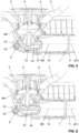
- the actuating lever 12 is pivoted about the lever axis 17 by the actuating element 13 and thereby lifts the valve body 9 from the closed position as in the Figure 5 shown in the open position as in the Figure 6 shown.
- the lever axis 17 is mounted in a bearing point 18 in a side wall 19 of the drain valve housing 1, wherein the lever axis 18 protrudes from the drain valve housing 1 and wherein the lever axis 18, in particular at the end, has a lever attachment 20 with a pivot point 21 on which the actuator element 13 acts.
- the lever attachment 20 and pivot point 21 are also located in the said installation space B.
- Drain valve arrangement 31 Pipe section 2 Sanitary ware 32 poetry 3 Drain valve housing 33 Deflection section 4 first canal section 34 Paragraph 5 Inlet opening 35 Pipe section 6 second canal section 36 poetry 7 Outlet opening 37 Side edges 8th Valve seat 38 Section 9 Valve body 10 Actuator unit A Distance 11 drain pipe B Installation space 12 Operating lever C Installation space 13 Actuator element M4 Central axis of first canal section 14 Storage location 15 Warehouse opening M6 Central axis of second channel section 16 Shell surface 17 Lever axis M11 Center axis drain pipe 18 Storage location VE Vertical plane 19 Side wall MY Middle level 20 Leverage approach OE upper level 21 Articulation point UE lower level 22 Lever arm OM upper surface line 23 Overflow unit AROUND lower mantle line 24 first connecting pipe 25 Overflow pipe S Swivel axis 26 second connecting pipe 27 upper mouth opening 28 lower mouth openings 29 Estuary section 30 Estuary section
Landscapes
- Engineering & Computer Science (AREA)
- Mechanical Engineering (AREA)
- Environmental & Geological Engineering (AREA)
- Health & Medical Sciences (AREA)
- Life Sciences & Earth Sciences (AREA)
- Hydrology & Water Resources (AREA)
- Public Health (AREA)
- Water Supply & Treatment (AREA)
- Sink And Installation For Waste Water (AREA)
- Multiple-Way Valves (AREA)
Description
- Die vorliegende Erfindung betrifft eine Ablaufanordnung für einen Sanitärartikel, insbesondere für ein Waschbecken oder ein Spülbecken, nach Anspruch 1.
- Ablaufanordnungen für Waschbecken oder Spülbecken sind aus dem Stand der Technik bekannt.
- Beispielsweise offenbart die
EP 2 045 403 eine Ablaufanordnung mit einer Überlaufeinheit. Die Überlaufeinheit erstreckt sich mit Verbindungsrohren von einem Ablaufventilgehäuse weg und entgegen der Lotrichtung nach oben. Nach unten hin weist das Ablaufventilgehäuse einen Rohrstutzen auf, dem sich ein Siphon und eine Abflussleitung anschliessen. - Obwohl die
EP 2 045 403 viele Vorteile aufweist, ist es ein Nachteil, dass der Bauraum nach unten hin vergleichsweise viel Platz einnimmt, was für das Volumen eines unterhalb des Waschbeckens anzuordnenden Unterschrank nachteilig ist. - Die
FR 2 164 018 WO 2017/042537 offenbaren weitere Ablaufanordnungen. - Aus der Praxis ergeben sich verschiedene Anforderungen an Ablaufanordnungen. Beispielsweise ist die Kompaktheit einer Ablaufanordnung, so dass diese nur einen kleinen Einbauraum einnimmt, ein zentrales Bedürfnis.
- Ausgehend von diesem Stand der Technik liegt der Erfindung eine Aufgabe zugrunde, eine Ablaufanordnung anzugeben, welche die Nachteile des Standes der Technik überwindet. Insbesondere ist eine Aufgabe der vorliegenden Erfindung, eine Ablaufanordnung anzugeben, welche, insbesondere vom Sanitärartikel nach unten hin, möglichst kompakt ausgebildet ist.
- Diese Aufgabe löst eine Ablaufanordnung gemäss Anspruch 1. Demgemäss umfasst eine Ablaufanordnung zum Anschluss an einen Sanitärartikel ein Ablaufventilgehäuse mit einem ersten Kanalabschnitt mit einer Einlauföffnung, einem zweiten Kanalabschnitt mit einer Auslauföffnung, die seitlich zum Ablaufventilgehäuse liegt, und einem zwischen der Einlauföffnung und der Auslauföffnung liegenden Ventilsitz, einen vom Ventilsitz von einer Verschlussstellung in eine Offenstellung bewegbaren Ventilkörper, eine Betätigungseinheit, mit welche der Ventilkörper bewegbar ist, und ein Abflussrohr, das sich der Auslauföffnung anschliesst. Mittig durch den ersten Kanalabschnitt verläuft eine erste Mittelachse und mittig durch das Abflussrohr verläuft eine Abflussrohrmittelachse. In einer Variante schneidet die Abflussrohrmittelachse die erste Mittelachse. In einer anderen Variante steht die Abflussrohrmittelachse in einem Abstand zur ersten Mittelachse, wobei der Abstand maximal dem halben Durchmesser der Auslauföffnung entspricht.
- Die Ablaufanordnung umfasst weiterhin eine Überlaufeinheit, wobei die Überlaufeinheit ein erstes Verbindungsrohr, ein Überlaufrohr und ein zweites Verbindungsrohr aufweist. Das erste Verbindungsrohr wird aus einer oberen Mündungsöffnung von oberhalb des Ventilsitzes aus dem ersten Kanalabschnitt geführt. Weiter mündet das erste Verbindungsrohr in das Überlaufrohr, welches sich in Einbaulage im Wesentlichen entgegen der Lotrichtung nach oben erstreckt. Das Überlaufrohr mündet sodann unterhalb des ersten Verbindungsrohrs in das zweite Verbindungsrohr, welches unterhalb des Ventilsitzes über eine untere Mündungsöffnung in den ersten Kanalabschnitt und/oder den zweiten Kanalabschnitt mündet.
- Sowohl die Auslauföffnung als auch die Mündungsöffnungen sind seitlich zum Ablaufventilgehäuse am Ablaufventilgehäuse angeordnet, derart, dass das Abflussrohr und die Verbindungsrohre in Einbaulage gesehen im Wesentlichen nebeneinander verlaufen. Das Abflussrohr und die Verbindungsrohre erstrecken sich und liegen seitlich nebeneinander.
- Durch die seitliche Anordnung der Mündungsöffnungen am Ablaufventilgehäuse und die seitliche Anordnung der Auslauföffnung am Ablaufventilgehäuse mit der damit einhergehenden Anordnung des Abflussrohrs ergeht der Vorteil, dass die benötigte Bauhöhe der Ablaufanordnung minimiert werden kann. Insbesondere kann der Bauraum vom Sanitärartikel nach unten hin minimiert werden, wodurch der Raum unterhalb des Sanitärartikels und der Ablaufanordnung durch einen Unterschrank oder eine andere Struktur besser genutzt werden kann.
- Unter der Ausdrucksweise "seitlich zum Ablaufventilgehäuse" wird verstanden, dass die Mündungsöffnungen und die Auslauföffnung in einer Seitenwand des Ablaufventilgehäuses liegen.
- In Einbaulage gesehen verläuft die erste Mittelachse des ersten Kanalabschnitts im Wesentlichen in der Vertikalen bzw. in der Lotrichtung.
- Der zweite Kanalabschnitt weist eine sich mittig durch den zweiten Kanalabschnitt erstreckende Mittelachse auf. Die erste Mittelachse steht in einem Winkel mindestens 90° zur zweiten Mittelachse bzw. zur Abflussrohrmittelachse. Besonders bevorzugt sind Winkel zwischen 90° und 95°. In Einbaulage verläuft die zweite Mittelachse bzw. die Abflussrohrmittelachse somit in der Horizontalen oder mit leichtem Gefälle zur Horizontalen.
- Vorzugsweise ist die Abflussrohrmittelachse im Wesentlichen parallel, insbesondere kollinear, zur zweiten Mittelachse orientiert.
- Vorzugsweise liegt der Ventilsitz im ersten Kanalabschnitt. Der Ventilsitz erstreckt sich um die erste Mittelachse herum.
- Vorzugsweise werden die Mündungsöffnungen durch jeweils einen Mündungskanalabschnitt bereitgestellt, welcher Mündungskanalabschnitt sich in einem Winkel, insbesondere in einem Winkel von 45° bis 135°, besonders bevorzugt in einem Winkel von 90°, winklig geneigt zur Abflussrohrmittelachse erstreckt.
- Mit anderen Worten erstrecken sich die Mündungskanalabschnitte jeweils entlang einer Mündungsmittelachse. Die Mündungsmittelachsen verlaufen winklig geneigt, insbesondere in einem Winkel von 45° bis 135°, besonders bevorzugt in einem Winkel von 90°, zur Rohrmittelachse.
- Vorzugsweise sind die Mündungsöffnungen stirnseitig durch Seitenkanten begrenzt. Die Seitenkanten der Mündungsöffnungen liegen in einer gemeinsamen Ebene, welche parallel oder in einem Winkel von maximal 45° zu einer durch die erste Mittelachse und die Rohrmittelachse sich erstreckende Mittelebene liegt.
- Vorzugsweise verlaufen die beiden Verbindungsrohre seitlich neben dem und beabstandet zum Abflussrohr, wobei die Verbindungsrohrmittelachsen in Einbaulage von oben gesehen parallel zur Abflussrohrmittelachse verlaufen.
- Von der Seite her gesehen, können die Verbindungsrohrmittelachsen parallel oder winklig geneigt zur Abflussrohrmittelachse verlaufen.
- Vorzugsweise ragen die Verbindungsrohre jeweils mit einem Rohrabschnitt in die Mündungsöffnungen ein.
- Vorzugsweise ist zwischen dem Rohrabschnitt und der Mündungsöffnung eine Dichtung angeordnet.
- Vorzugsweise weist die Dichtung einen Abschnitt auf, welcher in der Mündungsöffnung frei liegt, wobei der Abschnitt als winklige Fläche ausgebildet ist. Hierdurch kann eine strömungsoptimierte Kontur geschaffen werden.
- Vorzugsweise ist zwischen der Mündungsöffnung und dem jeweiligen Verbindungsrohr ein Umlenkabschnitt vorhanden, wobei der Umlenkabschnitt Teil der Mündungsöffnung und/oder Teil des Verbindungsrohrs ist. Mit dem Umlenkabschnitt wird eine Umlenkung erreicht, so dass sich die beiden Verbindungsrohre seitlich neben dem Abflussrohr erstrecken können.
- Vorzugsweise liegen die Verbindungsrohrmittelachsen in Einbaulage bezüglich einer Horizontalebene winklig geneigt, wobei die Verbindungsrohre zu den Mündungsöffnungen hin abfallend liegen. Hierdurch ergeht der Vorteil, dass beim Notüberlauf das untere Verbindungsrohr mit Gefälle ausgebildet ist, so dass ein guter Abfluss bereitgestellt werden kann.
- Vorzugsweise weisen das zweite Verbindungsrohr und/oder die untere Mündungsöffnung vor dem Eintritt in den ersten Kanalabschnitt einen Absatz auf, welcher in Richtung der Schwerkraft nach unten hin orientiert ist. Mit diesem Absatz wird erreicht, dass das Verbindungsrohr in Einbaulage leicht höher liegen kann. Darüber hinaus wird beim Überströmen des Absatzes eine leicht höhere Fliessgeschwindigkeit erreicht, was für den Abfluss von grossem Vorteil ist.
- Die beiden Verbindungsrohrmittelachsen verlaufen vorzugsweise parallel zueinander.
- Vorzugsweise sind die beiden Verbindungsrohre einstückig miteinander ausgebildet.
- Vorzugsweise lässt sich das Überlaufrohr mit den Verbindungsrohren über eine Steckverbindung verbinden. Die Steckverbindung kann weiter eine Dichtung aufweisen.
- Die Überlaufeinheit liegt in einem Bauraum, welcher Bauraum sich seitlich zum Abflussrohr und nach oben hin erstreckt. Der Bauraum ist in Einbaulage nach unten hin durch eine untere Ebene begrenzt. Die untere Ebene erstreckt sich rechtwinklig zu einer durch die erste Mittelachse und die zweite Mittelachse aufgespannte Mittelebene. Weiter erstreckt sich die untere Ebene durch eine untere Mantellinie, welche die Schnittlinie einer durch die Abflussrohrmittelachse sich erstreckende und in der Vertikalen verlaufende Vertikalebene mit der Rohraussenseite bildet. Diese Anordnung hat den Vorteil, dass bezüglich der Bauhöhe unterhalb des Sanitärartikels eine kompakte Struktur geschaffen werden kann.
- Die Ausdrucksweise "Bauraum" ist als Raumbereich zu verstehen, in welchem die Überlaufeinheit angeordnet ist.
- Vorzugsweise erstreckt sich das Abflussrohr entlang einer Geraden ohne Krümmung. Vorzugsweise schliesst sich dem Abflussrohr gegenüber des zweiten Kanalabschnitts ein Siphonelement an.
- Vorzugsweise weist das Abflussrohr eine Länge von grösser als 300 Millimeter auf.
- Vorzugsweise weist die Betätigungseinheit weiter einen auf den Ventilkörper wirkenden Betätigungshebel und ein Aktuatorelement zur Betätigung des Betätigungshebels auf, wobei sich das Aktuatorelement mindestens abschnittsweise seitlich neben dem Abflussrohr erstreckt.
- Durch die seitliche Anordnung des Aktuatorelements ergeht der Vorteil, dass eine kompakte Struktur bereitgestellt werden kann. Das heisst, dass die Höhe der Ablaufanordnung minimiert werden kann, was den benötigten Raumbedarf unterhalb des Sanitärartikels verkleinert.
- Durch diese seitliche Anordnung ergeht der weitere Vorteil, dass das durch das Ablaufventilgehäuse abfliessende Wasser nur zwischen dem ersten Kanalabschnitt und dem zweiten Kanalabschnitt umgelenkt wird und dann bei der einen Variante direkt in das Abflussrohr fliesst bzw. bei der anderen Variante nur eine geringe Umlenkung aufgrund des Versatzes der ersten Mittelachse zur Abflussrohrmittelachse erfährt.
- Unter der Ausdrucksweise "seitlich neben dem Abflussrohr" wird verstanden, dass das Aktuatorelement in Einbaulage neben dem Abflussrohr liegt und sich neben dem Abflussrohr erstreckt.
- Vorzugsweise liegt das Aktuatorelement auf der einen Seite des Abflussrohrs und die beiden Verbindungsrohre sowie das Überlaufrohr liegen auf der anderen Seite des Abflussrohrs.
- Vorzugsweise liegen die Mündungsöffnungen bezüglich einer durch die erste Mittelachse und die zweite Mittelachse aufgespannte Mittelebene gegenüber dem Aktuatorelement.
- Vorzugsweise ist das Aktuatorelement in einer am Ablaufventilgehäuse aussenseitig liegenden Lagerstelle gelagert, wobei die Lagerstelle eine Lageröffnung für die Durchführung des Aktuatorelements aufweist. Die Lagerung ist dabei derart, dass das Aktuatorelement relativ zur feststehenden Lagerung bewegbar ist.
- Die Lagerstelle ist vorzugsweise integral am Ablaufventilgehäuse angeformt. Die Lagerstelle kann aber auch an einem separaten Element angeordnet sein, welches mit dem Ablaufventilgehäuse verbunden werden kann.
- Die Lagerstelle liegt seitlich am Ablaufventilgehäuse.
- Vorzugsweise liegt die Lagerstelle bzw. die Lageröffnung in Einbaulage auf einer Höhenlage mittig zum Abflussrohr.
- Vorzugsweise liegt das Aktuatorelement in einem Abstand seitlich beabstandet zur Mantelfläche des Abflussrohrs, wobei der Abstand weniger als der Aussendurchmesser des Abflussrohrs beträgt oder wobei der Abstand weniger als der halbe Aussendurchmesser des Abflussrohrs beträgt.
- Durch den geringen Abstand zum Abflussrohr ergeht der Vorteil, dass der benötigte Bauraum der Ablaufventilanordnung bezüglich ihrer Breite minimiert werden kann.
- Vorzugsweise weist der Betätigungshebel eine Hebelachse auf, wobei der Betätigungshebel um die Hebelachse verschwenkbar ist und wobei die Hebelachse rechtwinklig zur ersten Mittelachse und zur zweiten Mittelachse verläuft.
- Besonders bevorzugt liegt die Hebelachse in Einbaulage gesehen unterhalb der Abflussrohrmittelachse.
- Vorzugsweise ist die Hebelachse in einer Lagerstelle in einer Seitenwand des Ablaufventilgehäuses gelagert, wobei die Hebelachse aus dem Ablaufventilgehäuse hinausragt und wobei die Hebelachse, insbesondere endseitig, einen Hebelansatz mit einer Anlenkstelle aufweist, auf welche das Aktautorelement einwirkt.
- Vorzugsweise weist der Betätigungshebel einen Hebelarm auf, welcher auf den Ventilkörper wirkt. Der Hebelarm ragt von der Hebelachse weg und befindet sich im ersten und/oder im zweiten Kanalabschnitt.
- Die Lage des Aktuatorelements kann über einen Bauraum spezifiziert werden. Vorzugsweise liegt das Aktuatorelement im Bauraum, wobei der Bauraum sich seitlich zum Abflussrohr erstreckt.
- Die Ausdrucksweise "Bauraum" ist als Raumbereich zu verstehen, in welchem das Aktuatorelement angeordnet ist.
- Vorzugsweise liegt der Hebelansatz in einem Bauraum, welcher Bauraum sich seitlich zum Abflussrohr erstreckt.
- Vorzugsweise wird der Bauraum seitlich durch die Aussenseite des Abflussrohrs und durch eine Vertikalebene begrenzt. Die Vertikalebene verläuft in Einbaulage in der Vertikalen und steht in einem Abstand von maximal dem Aussendurchmesser des Abflussrohrs oder von maximal dem halben Aussendurchmesser des Abflussrohrs beabstandet zur Mantelfläche des Abflussrohrs. Die Vertikalebene verläuft parallel zur ersten Mittelachse und parallel zur zweiten Mittelachse bzw. der Abflussrohrmittelachse.
- Nach unten hin kann der Bauraum vorzugsweise durch eine untere Ebene begrenzt sein. Die untere Ebene erstreckt sich rechtwinklig zur Vertikalebene und durch eine untere Mantellinie, die die Schnittlinie einer durch die Abflussrohrmittachse sich erstreckende und in der Vertikalen verlaufende Mittelebene mit der Rohraussenseite bildet.
- Nach oben hin kann der Bauraum durch eine obere Ebene begrenzt sein. Die obere Ebene erstreckt sich rechtwinklig zur Vertikalebene und durch eine obere Mantellinie, die die Schnittlinie einer durch die Abflussrohrmittachse sich erstreckende Mittelebene mit der Rohraussenseite bildet.
- Vorzugsweise ist Aktuatorelement eine Betätigungsstange oder ein Seil.
- Weitere Ausführungsformen sind in den abhängigen Ansprüchen angegeben.
- Bevorzugte Ausführungsformen der Erfindung werden im Folgenden anhand der Zeichnungen beschrieben, die lediglich zur Erläuterung dienen und nicht einschränkend auszulegen sind. In den Zeichnungen zeigen:
- Fig. 1
- eine perspektivische Ansicht einer Ablaufventilanordnung nach einer Ausführungsform der vorliegenden Erfindung;
- Fig. 2
- eine Seitenansicht der Ablaufanordnung nach
Figur 1 in der Verschlussstellung; - Fig. 3
- eine Seitenansicht der Ablaufanordnung nach
Figur 1 in der Offenstellung; - Fig. 4
- eine Frontansicht der Ablaufanordnung nach
Figur 1 ; - Fig. 5
- eine Seitenansicht der Ablaufanordnung nach
Figur 1 in der Verschlussstellung; - Fig. 6
- eine Seitenansicht der Ablaufanordnung nach
Figur 1 in der Offenstellung; - Fig. 7
- eine Explosionsdarstellung der Ablaufanordnung nach
Figur 1 ; - Fig. 8
- eine weitere Explosionsdarstellung der Ablaufanordnung nach
Figur 1 ; - Fig. 9
- eine weitere Schnittdarstellung der Ablaufanordnung nach
Figur 1 ; und - Fig. 10
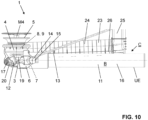
- eine Seitenansicht der zweiten Ausführungsform mit einem anderen Betätigungselement.
- In den
Figuren 1 bis 10 werden verschiedene Ansichten einer bevorzugten Ausführungsform einer erfindungsgemässen Ablaufanordnung gezeigt. DieFiguren 1 bis 9 zeigen eine erste Variante der bevorzugten Ausführungsform und dieFigur 10 zeigt eine Variante davon. - Die Ablaufventilanordnung 1 dient dem Anschluss an einen Sanitärartikel 2. Der Sanitärartikel 2 ist vorzugsweise ein Waschbecken oder ein Spülbecken. Die Ablaufanordnung 1 umfasst ein Ablaufventilgehäuse 3 mit einem ersten Kanalabschnitt 4 mit einer Einlauföffnung 5, einen zweiten Kanalabschnitt 6 mit einer Auslauföffnung 7 und einen zwischen der Einlauföffnung 5 und der Auslauföffnung 7 liegenden Ventilsitz 8. Weiter umfasst die Ablaufventilanordnung 1 einen vom Ventilsitz 8 von einer Verschlussstellung in eine Offenstellung und zurück bewegbaren Ventilkörper 9. Der Ventilkörper 9 wird mit einer Betätigungseinheit 10 von der Verschlussstellung in die Offenstellung bewegt. Weiter umfasst die Ablaufventilanordnung 1 ein Abflussrohr 11, in welches der zweite Kanalabschnitt 6 mit seiner Auslauföffnung 7 mündet. Über das Abflussrohr 11 kann Wasser aus dem zweiten Kanalabschnitt 6 weggeführt werden.
- Mittig durch den ersten Kanalabschnitt 4 verläuft eine erste Mittelachse M4. In Einbaulage steht die erste Mittelachse M4 im Wesentlichen in der Vertikalen, das heisst, in Lotrichtung. Mittig durch das Abflussrohr 11 verläuft eine Abflussrohrmittelachse M11. In Einbaulage verläuft die Abflussrohrmittelachse M11 im Wesentlichen in der Horizontalen oder bezüglich der Horizontalen winklig geneigt nach unten, so dass Wasser durch das Abflussrohr vom Ablaufventilgehäuse 3 weg gefördert werden kann. Der zweite Kanalabschnitt 6 weist eine zweite Mittelachse M6 auf.
- In den gezeigten Ausführungsformen schneidet die Abflussrohrmittelachse M11 die erste Mittelachse M4. Das heisst, die Mittelachse M11 und die Mittelachse M4 liegen in einer gemeinsamen Ebene, welche als Mittelebene ME bezeichnet werden kann. Die Abflussrohrmittelachse M11 kann aber auch in einem Abstand zur ersten Mittelachse M4 stehen, wobei dieser Abstand maximal dem halben Durchmesser der Auslauföffnung 7 entspricht.
- Weiter umfasst die Ablaufanordnung 1 eine Überlaufeinheit 23. Mit der Überlaufeinheit 23 kann ein Notüberlauf geschaffen werden, wenn der Ventilkörper 9 in der Verschlussstellung ist. Die Überlaufeinheit 23 weist ein erstes Verbindungsrohr 24, ein Überlaufrohr 25 und ein zweites Verbindungsrohr 26 auf. Das erste Verbindungsrohr 24 wird aus einer oberen Mündungsöffnung 27 von oberhalb des Ventilsitzes 8 aus dem ersten Kanalabschnitt 4 geführt. Die Mündungsöffnung 27 bildet einen Durchbruch durch die Seitenwand 19 des Abfblaufventilgehäuses 3. Das erste Verbindungsrohr 24 mündet in das Überlaufrohr 25, welches sich in Einbaulage im Wesentlichen entgegen der Lotrichtung nach oben erstreckt. Im Inneren des Überlaufrohrs 25 ist eine Überlaufkante angeordnet. Das Überlaufrohr 25 mündet sodann unterhalb des ersten Verbindungsrohrs 24 in das zweite Verbindungsrohr 26. Das zweite Verbindungsrohr 26 mündet unterhalb des Ventilsitzes 8 über eine untere Mündungsöffnung 28 in den ersten Kanalabschnitt 4. Die untere Mündungsöffnung 28 bildet ebenfalls einen Durchbruch durch die Seitenwand 19.
- Die Mündungsöffnungen 27, 28 münden seitlich zum Ablaufventilgehäuse 3 in das Ablaufventilgehäuse 3. Gleichwohl mündet das Abflussrohr 11 seitlich zum Ablaufventilgehäuse 3 in das Ablaufventilgehäuse 3 ein. Durch dieses seitliche Einmünden ergeht der Vorteil, dass die Ablaufanordnung nach unten hin sehr kompakt ausgebildet werden kann.
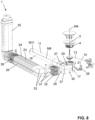
- Die Mündungsöffnungen 27, 28 werden in der gezeigten Ausführungsform durch jeweils einen Mündungskanalabschnitt 29, 30 bereitgestellt. Die Mündungskanalabschnitte 29, 30 erstreckt sich, wie in der
Figur 8 gut ersichtlich, seitlich vom Ablaufventilgehäuse 3 weg. Die Mündungskanalabschnitt 29, 30 stehen in einem Winkel winklig geneigt zur Abflussrohrmittelase M11. Der Winkel ist in der gezeigten Ausführungsform ein rechter Winkel. Andere Winkel im Bereich von 45° bis 135° sind ebenfalls denkbar. - Stirnseitig sind die Mündungsöffnungen 27, 28 durch Seitenkanten 37 begrenzt. Die Seitenkanten 37 liegen in einer Ebene, die parallel oder in einem Winkel von maximal 45° zu einer durch die erste Mittelachse M4 und die Rohrmittelachse M11 sich erstreckende Mittelebene ME liegt.
- Wie von allen Figuren ersichtlich verlaufen die beiden Verbindungsrohre 24, 26 seitlich neben dem Abflussrohr 11, wobei die Verbindungsrohrmittelachsen M24, M26 in Einbaulage von oben gesehen parallel zur Abflussrohrmittelachse M11 verlaufen. In den
Figuren 2 und 3 wird die Orientierung der beiden Verbindungsrohre 24, 26 gezeigt. Die Verbindungsrohrmittelachsen M24, M26 liegen in Einbaulage bezüglich einer Horizontalebene HE winklig geneigt, wobei die Verbindungsrohre 24, 26 zu den Mündungsöffnungen 27, 28 hin abfallend liegen. Mit anderen Worten liegen die Verbindungsrohrmittelachsen M24, M26 winklig geneigt zur Abflussrohrmittelachse M11. - Weiter ist zwischen den Mündungsöffnungen 27, 28 und dem jeweiligen Verbindungsrohr 24, 26 ein Umlenkabschnitt 33 vorhanden. Der Umlenkabschnitt 33 ist in der gezeigten Ausführungsform Teil des Verbindungsrohrs 24, 26.
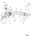
- Die Verbindungsrohre 24, 26 ragen jeweils mit einem Rohrabschnitt 31 in die Mündungsöffnungen 27, 28 ein. Zwischen den Rohrabschnitten 31 und den Mündungsöffnungen 27, 28 ist jeweils eine Dichtung 32 angeordnet.
- Das Überlaufrohr 25 ragt jeweils mit einem Rohrabschnitt 35 in die Verbindungsrohre 24, 26 ein. Zwischen den Rohrabschnitten 31 und den Mündungsöffnungen 27, 28 ist jeweils eine Dichtung 36 angeordnet.
- In den
Figuren 7 und8 werden die Dichtungen 32 und 36 gezeigt. Die Dichtung 32, 36 sind vorzugsweise einstückig ausgebildet, derart, dass pro Seite mit einem Element, das heisst mit einer Dichtung, die Dichtwirkung bereitgestellt werden kann. - Das erste Verbindungsrohr 24 und das zweite Verbindungsrohr 26 sind vorzugsweise als einstückige Struktur ausgebildet.
- In der
Figur 9 wird eine geschnittene Darstellung des Ablaufventilgehäuses 3 und der Mündungsstellen der beiden Verbindungsrohre 24, 26 genauer gezeigt. - Die Dichtung 32 weist einen Abschnitt 33 auf, welcher in der Mündungsöffnung 27, 28 frei liegt, wobei der Abschnitt 33 als winklige Fläche ausgebildet ist. Die winklige ausgebildete Fläche hat den Vorteil, dass der Strömungswiderstand beim Übergang vom Verbindungsrohr 24, 26 reduziert werden kann, was für die Überlaufleistung von Vorteil ist.
- Weiter weist das zweite Verbindungsrohr 26 vor dem Eintritt in den ersten Kanalabschnitt 4 einen Absatz 34 auf, welcher in Richtung der Schwerkraft nach unten hin orientiert ist. Der Absatz 34 hat den Vorteil, dass in Richtung Ablaufventilgehäuse 3 den Absatz 34 überfliessendes Wasser im Bereich des Absatz 34 beschleunigt wird. Zudem kann durch den Absatz 34 das zweite Verbindungsrohr 26 bezüglich seiner Lage weiter oben angeordnet sein.
- Die Betätigungseinheit 10 weist einen auf den Ventilkörper 9 wirkenden Betätigungshebel 12 und Aktuatorelement 13 zur Betätigung des Betätigungshebels 12 auf. Der Betätigungshebel 12 ragt in der gezeigten Ausführungsform durch eine Seitenwand 19 von ausserhalb des Ablaufventilgehäuses 3 in das Innere des Ablaufventilgehäuses 3 ein. Das Aktuatorelement 13 ist aussenseitig zum Abflussrohr 11 angeordnet und erstreckt sich mindestens abschnittsweise seitlich neben dem Abflussrohr 11. Das Aktuatorelement ist der Variante der
Figuren 1 bis 9 als Betätigungsstange und in der Variante derFigur 10 als Seilzug ausgebildet. - Die Ausdrucksweise seitlich neben dem Abflussrohr 11 ist so zu verstehen, dass das Aktuatorelement 13 in Einbaulage auf dem besagten Abschnitt neben dem Abflussrohr 11 liegt und nicht unterhalb oder oberhalb vom Rohr. Auf der dem Aktuatorelement 13 gegenüberliegenden Seite, sprich auf der anderen Seite des Abflussrohrs, erstreckt sich die Überlaufeinheit 23. Diese Lage des Aktuatorelements 11 wird anhand eines Bauraums weiter unten noch genauer spezifiziert.
- Die seitliche Anordnung von der Überlaufeinheit 23 und des Aktuatorelements 13 jeweils neben dem Abflussrohr weist, wie von den Figuren gezeigt wird, den Vorteil auf, dass eine kompakte Ablaufanordnung 1 bereitgestellt werden kann. Dies insbesondere unter der Massgabe einer bezüglich Strömungsverlusten vorteilhaften Rohrführung. In der gezeigten Ausführungsform weist die Ablaufanordnung 1 nur eine einzige Umlenkung auf, nämlich im Übergang vom ersten Kanalabschnitt 4 zum zweiten Kanalabschnitt 6. Anschliessend erstreckt sich vom zweiten Kanalabschnitt 6 direkt das Abflussrohr 11, welches hier gerade ausgebildet ist. Dies hat den Vorteil, dass die Strömungsverluste beim Abfliessen des Wassers gering sind. Weiter ergeht durch die Anordnung der Überlaufeinheit 23 und des Aktuatorelements 13 neben dem Abflussrohr der Vorteil, dass die Ablaufventilanordnung nach unten hin mit einer geringen Bauhöhe ausgebildet ist.
- Das Akturatorelement 13 verläuft im besagten seitlich zum Abflussrohr 11 verlaufenden Abschnitt in einem Abstand A seitlich zum Abflussrohr 11. Der Abstand A ist möglichst klein gewählt. Insbesondere beträgt der Abstand A weniger als der Aussendurchmesser D oder weniger als der halbe Aussendurchmesser D des Abflussrohrs 11.
- In allen Ausführungsformen ist das Aktuatorelement 13 in einer am Ablaufventilgehäuse aussenseitig liegenden Lagerstelle 14 gelagert. Die Lagerstelle 14 liegt ebenfalls seitlich zum Ablaufventilgehäuse 3. Die Lagerstelle 14 weist dabei eine Lageröffnung 15 für die Durchführung des Aktuatorelementes 13 auf. Wenn das Aktuatorelement 13 eine Betätigungsstange ist, so ist die Lagerstelle 14 mit der Lageröffnung 15 derart ausgebildet, dass eine Verschwenkung der Stange um eine Schwenkachse S möglich ist. Sofern das Aktuatorelement ein Seilzug ist, dient die Lageröffnung der Durchführung des Seils. Bei einer bevorzugten Ausführungsform der Ablaufventilanordnung können, wie in den Figuren gezeigt, zwei Lageröffnungen angeordnet sein, so dass entweder die Betätigungsstange oder der Seilzug durch die Lageröffnung geführt werden kann.
- Die Lagerstelle 14 bzw. die Lageröffnung 15 liegen in Einbaulage auf einer Höhenlage, welche im Wesentlichen mittig zum Abflussrohr 11 liegt. Das heisst, die Lagerstelle 14 bzw. die Lageröffnung 15 liegen in Einbaulage im Wesentlichen auf Höhe der Mittelachse M6 des zweiten Kanalabschnittes.
- Anhand der
Figur 4 wird nun der Bauraum B, in welchem das Aktuatorelement 13 und die ausserhalb des Ablaufventilgehäuses 3 liegende Teile des Betätigungshebels liegen, genauer erläutert. Gleichermassen wird der Bauraum C für die Überlaufeinheit 23 genauer erläutert. - Seitlich ist der Bauraum B durch eine Vertikalebene VE begrenzt. Die Vertikalebene VE verläuft in Einbaulage in der Vertikalen und erstreckt sich parallel zur Abflussrohrmittelachse M11 sowie zur ersten Mittelachse M4 und zur zweiten Mittelachse M6. Die Vertikalebene steht in einem Abstand zur Mantelfläche des Abflussrohrs 11. Der Abstand trägt das Bezugszeichen A. Der Abstand A entspricht maximal dem Aussendurchmesser D des Abflussrohrs 11.
- Nach unten hin ist der Bauraum B durch eine untere Ebene UE begrenzt. Die untere Ebene UE erstreckt sich rechtwinklig zur Vertikalebene VE. Weiter erstreckt sich die untere Ebene UE durch eine untere Mantellinie UM. Die untere Mantellinie UM ist die untere Schnittlinie der Mantelfläche des Abflussrohrs 11 mit einer durch die Abflussrohrmittelachse M11 und in der Vertikalen verlaufende Mittelebene ME. Die Mittelebene ME verläuft parallel durch die Vertikalebene VE.
- In der Variante, bei welcher sich die Abflussrohrmittelachse M11 mit der ersten Mittelachse M4 schneidet, erstreckt sich die Mittelebene ME auch durch die erste Mittelachse M4 und durch die zweite Mittelachse M6. Mit anderen Worten gesagt wird die Mittelebene ME durch die Abflussrohrmittelachse M11, die erste Mittelachse M4 und die zweite Mittelachse M6 aufgespannt. In der Variante, bei welcher die Abflussrohrmittelachse M11 in einem Abstand zur ersten Mittelachse M4 steht, verläuft die Mittelebene beabstandet und parallel zur ersten Mittelachse M4.
- Nach oben hin ist der Bauraum B durch eine obere Ebene OE begrenzt. Die obere Ebene OE erstreckt sich rechtwinklig zur Vertikalebene VE. Weiter erstreckt sich die obere Ebene OE durch eine obere Mantellinie OM. Die obere Mantellinie OM ist die obere Schnittlinie der oben definierten Mittelebene ME mit der Mantelfläche des Abflussrohrs 11.
- Der Bauraum B verläuft, wie in der
Figur 4 gezeigt, seitlich neben dem Abflussrohr 11, wobei der Bauraum B räumlich eng am Abflussrohr 11 anliegt. - Die ausserhalb vom Ablaufventilgehäuse 3 liegenden Elemente der Betätigungseinheit 10 liegen, wie beschrieben, im Bauraum B. Je nach Ausbildung des Aktuatorelements 13 wird die obere Ebene OE durch das Aktuatorelement 13 durchdrungen. Bei der Ausführung des Aktuatorelements 13 als Betätigungsstange, erstreckt sich die Betätigungsstange wie in den
Figuren 1 bis 7 und8 bis 14 gezeigt im Wesentlichen über die ganze Länge des Abflussrohrs 13 im besagten Bauraum B bzw. unterhalb der oberen Ebene OE. Im Endbereich des Abflussrohrs 13 gegenüber dem Ablaufventilgehäuse 3 durchdringt das Aktuatorelement 13 den Bauraum B. Bei der Ausführung des Aktuatorelements 13 als Seilzug kann der Seilzug bereits früher die obere Ebene OE durchdringen. Bei beiden Varianten liegt das Aktuatorelement 13 aber so, dass die untere Ebene UE und die Vertikalebene VE nicht durchdrungen werden. - Der Bauraum C, in welchem die Überlaufeinheit 23 liegt, erstreckt sich seitlich zum Abflussrohr 11 nach oben hin. Der Bauraum C ist in Einbaulage nach unten hin durch eine untere Ebene UE begrenzt. Die untere Ebene UE erstreckt sich rechtwinklig zu einer durch die erste Mittelachse M4 und die zweite Mittelachse M6 aufgespannte Mittelebene ME und durch eine untere Mantellinie UM, welche die Schnittlinie einer durch die Abflussrohrmittachse M11 sich erstreckende und in der Vertikalen verlaufende Vertikalebene VE mit der Rohraussenseite bildet, erstreckt.
- Von den Schnittdarstellungen der
Figuren 5 und 6 kann gut erkannt werden, dass der Betätigungshebel 12 einen Hebelarm 22 aufweist, welcher auf den Ventilkörper 9 wirkt. Der Betätigungshebel 12 wird durch das Aktautorelement 13 um die Hebelachse 17 verschwenkt und hebt dabei den Ventilkörper 9 von der Verschlussstellung wie in derFigur 5 gezeigt in die Offenstellung wie in derFigur 6 gezeigt. - Die Hebelachse 17 ist in einer Lagerstelle 18 in einer Seitenwand 19 des Ablaufventilgehäuses 1 gelagert, wobei die Hebelachse 18 aus dem Ablaufventilgehäuse 1 hinausragt und wobei die Hebelachse 18, insbesondere endseitig, einen Hebelansatz 20 mit einer Anlenkstelle 21 aufweist, auf welche das Aktautorelement 13 einwirkt. Hebelansatz 20 und Anlenkstelle 21 befinden sich ebenfalls im besagten Bauraum B.
-
1 Ablaufventilanordnung 31 Rohrabschnitt 2 Sanitärartikel 32 Dichtung 3 Ablaufventilgehäuse 33 Umlenkabschnitt 4 erster Kanalabschnitt 34 Absatz 5 Einlauföffnung 35 Rohrabschnitt 6 zweiter Kanalabschnitt 36 Dichtung 7 Auslauföffnung 37 Seitenkanten 8 Ventilsitz 38 Abschnitt 9 Ventilkörper 10 Betätigungseinheit A Abstand 11 Abflussrohr B Bauraum 12 Betätigungshebel C Bauraum 13 Aktuatorelement M4 Mittelachse erster Kanalabschnitt 14 Lagerstelle 15 Lageröffnung M6 Mittelachse zweiter Kanalabschnitt 16 Mantelfläche 17 Hebelachse M11 Mittelachse Abflussrohr 18 Lagerstelle VE Vertikalebene 19 Seitenwand ME Mittelebene 20 Hebelansatz OE obere Ebene 21 Anlenkstelle UE untere Ebene 22 Hebelarm OM obere Mantellinie 23 Überlaufeinheit UM untere Mantellinie 24 erstes Verbindungsrohr 25 Überlaufrohr S Schwenkachse 26 zweites Verbindungrohr 27 obere Mündungsöffnung 28 untere Mündungsöffnunge 29 Mündungskanalabschnitt 30 Mündungskanalabschnitt
Claims (15)
- Ablaufanordnung (1) zum Anschluss an einen Sanitärartikel (2) umfassendein Ablaufventilgehäuse (3) mit einem ersten Kanalabschnitt (4) mit einer Einlauföffnung (5), einem zweiten Kanalabschnitt (6) mit einer Auslauföffnung (7), die seitlich aus dem Ablaufventilgehäuse (3) austritt, und einem zwischen der Einlauföffnung (5) und der Auslauföffnung (7) liegenden Ventilsitz (8),einen vom Ventilsitz (8) von einer Verschlussstellung in eine Offenstellung bewegbaren Ventilkörper (9),eine Betätigungseinheit (10), mit welcher der Ventilkörper (9) bewegbar ist, undein Abflussrohr (11), das sich der Auslauföffnung (7) anschliesst,wobei mittig durch den ersten Kanalabschnitt (4) eine erste Mittelachse (M4) verläuft und mittig durch das Abflussrohr (11) eine Abflussrohrmittelachse (M11) verläuft,wobei die Abflussrohrmittelachse (M11) die erste Mittelachse (M4) schneidet oder wobei die Abflussrohrmittelachse (M11) in einem Abstand zur ersten Mittelachse (M4) steht, wobei der Abstand maximal dem halben Durchmesser der Auslauföffnung (7) entspricht,wobei die Ablaufanordnung (1) weiterhin eine Überlaufeinheit (23) umfasst, die ein erstes Verbindungsrohr (24), ein Überlaufrohr (25) und ein zweites Verbindungsrohr (26) aufweist,wobei das erste Verbindungsrohr (24) aus einer oberen Mündungsöffnung (27) von oberhalb des Ventilsitzes (8) aus dem ersten Kanalabschnitt (4) geführt wird und in das Überlaufrohr (25), welches sich in Einbaulage im Wesentlichen entgegen der Lotrichtung nach oben erstreckt, mündet und wobei das Überlaufrohr (25) unterhalb des ersten Verbindungsrohrs (24) in das zweite Verbindungsrohr (26) mündet, welches unterhalb des Ventilsitzes (8) über eine untere Mündungsöffnung (28) in den ersten Kanalabschnitt (4) und/oder den zweiten Kanalabschnitt (6) mündet, undwobei sowohl die Auslauföffnung (7) als auch die Mündungsöffnungen (27, 28) seitlich zum Ablaufventilgehäuse (3) am Ablaufventilgehäuse (3) angeordnet sind, derart, dass das Abflussrohr (11) und die Verbindungsrohre (24, 25) in Einbaulage gesehen im Wesentlichen nebeneinander verlaufen.
- Ablaufanordnung (1) nach Anspruch 1, dadurch gekennzeichnet, dass die Mündungsöffnungen (27, 28) durch jeweils einen Mündungskanalabschnitt (29, 30) bereitgestellt werden, welcher Mündungskanalabschnitt (29, 30) sich in einem Winkel, insbesondere in einem Winkel von 45° bis 135°, besonders bevorzugt in einem Winkel von 90°, winklig geneigt zur Abflussrohrmittelachse (M11) erstreckt.
- Ablaufanordnung (1) nach einem der vorhergehenden Ansprüche, dadurch gekennzeichnet, dass die Mündungsöffnungen (27, 28) stirnseitig durch Seitenkanten (37) begrenzt sind, welche in einer Ebene liegen, die, wenn die Abflussrohrmittelachse (M11) die erste Mittelachse (M4) schneidet, parallel oder in einem Winkel von maximal 45° zu einer durch die erste Mittelachse (M4) und die Abflussrohrmittelachse (M11) sich erstreckenden Mittelebene (ME) liegt.
- Ablaufanordnung (1) nach einem der vorhergehenden Ansprüche, dadurch gekennzeichnet, dass die beiden Verbindungsrohre (24, 26) seitlich neben dem und beabstandet zum Abflussrohr (11) verlaufen, wobei die Verbindungsrohrmittelachsen (M24, M26) in Einbaulage von oben gesehen parallel zur Abflussrohrmittelachse (M11) verlaufen.
- Ablaufanordnung (1) nach einem der vorhergehenden Ansprüche, dadurch gekennzeichnet, dass die Verbindungsrohre (24, 26) jeweils mit einem Rohrabschnitt (31) in die Mündungsöffnungen (27, 28) einragen.
- Ablaufanordnung (1) nach Anspruch 5, dadurch gekennzeichnet, dass zwischen den Rohrabschnitten (31) und Mündungsöffnungen (27, 28) jeweils eine Dichtung (32) angeordnet ist.
- Ablaufanordnung (1) nach Anspruch 6, dadurch gekennzeichnet, dass die Dichtung (32) einen Abschnitt (38) aufweist, welcher in der Mündungsöffnung (27, 28) frei liegt, wobei der Abschnitt als winklige Fläche ausgebildet ist.
- Ablaufanordnung (1) nach einem der vorhergehenden Ansprüche, dadurch gekennzeichnet, dass zwischen den Mündungsöffnungen (27, 28) und dem jeweiligen Verbindungsrohr (24, 26) ein Umlenkabschnitt (33) vorhanden ist, wobei der Umlenkabschnitt (33) Teil der Mündungsöffnung (27, 28) und/oder Teil des Verbindungsrohrs (24, 26) ist.
- Ablaufanordnung (1) nach einem der vorhergehende Ansprüche, dadurch gekennzeichnet, dass die Verbindungsrohrmittelachsen (M24, M26) in Einbaulage bezüglich einer Horizontalebene (HE) winklig geneigt liegen, wobei die Verbindungsrohre (24, 26) zu den Mündungsöffnungen (27, 28) hin abfallend liegen.
- Ablaufanordnung (1) nach einem der vorhergehenden Ansprüche, dadurch gekennzeichnet, dass das zweite Verbindungsrohr (26) und/oder die untere Mündungsöffnung (28) vor dem Eintritt in den ersten Kanalabschnitt (4) einen Absatz (34) aufweisen, welcher in Richtung der Schwerkraft nach unten hin orientiert ist.
- Ablaufanordnung (1) nach einem der vorhergehenden Ansprüche, dadurch gekennzeichnet, dass die Betätigungseinheit (10) einen auf den Ventilkörper (9) wirkenden Betätigungshebel (12) und ein Aktuatorelement (13) zur Betätigung des Betätigungshebels (12) aufweist, wobei sich das Aktuatorelement (13) mindestens abschnittsweise seitlich neben dem Abflussrohr (11) erstreckt.
- Ablaufanordnung nach Anspruch 11, dadurch gekennzeichnet, dass das Aktuatorelement (13) auf der einen Seite des Abflussrohrs (11) liegt und dass die beiden Verbindungsrohre (24, 26) sowie das Überlaufrohr (25) auf der anderen Seite des Abflussrohrs (11) liegen.
- Ablaufanordnung (1) nach Anspruch 11 oder 12, dadurch gekennzeichnet, dass die Mündungsöffnungen (27, 28) bezüglich einer durch die erste Mittelachse (M4) und eine zweite Mittelachse (M6) aufgespannte Mittelebene (ME) gegenüber dem Aktuatorelement (13) liegen.
- Ablaufanordnung (1) nach einem der vorhergehenden Ansprüche 11 bis 13, dadurch gekennzeichnet, dass das Aktuatorelement (13) in einem Abstand (A) seitlich beabstandet zur Mantelfläche (16) des Abflussrohrs (11) liegt, wobei der Abstand (A) weniger als der Aussendurchmesser des Abflussrohrs (11), insbesondere weniger als der halbe Aussendurchmesser des Abflussrohrs (11), beträgt.
- Ablaufanordnung (1) nach einem der vorhergehenden Ansprüche, dadurch gekennzeichnet, dass das Abflussrohr (11) sich entlang einer Geraden ohne Krümmung erstreckt; und/oder dass sich dem Abflussrohr (11) gegenüber des zweiten Kanalabschnitts (6) ein Siphon anschliesst.
Priority Applications (8)
| Application Number | Priority Date | Filing Date | Title |
|---|---|---|---|
| FIEP20174359.8T FI3910119T3 (fi) | 2020-05-13 | 2020-05-13 | Viemärijärjestely |
| EP20174359.8A EP3910119B1 (de) | 2020-05-13 | 2020-05-13 | Ablaufanordnung |
| AU2021202928A AU2021202928B2 (en) | 2020-05-13 | 2021-05-10 | Drain arrangement |
| AU2021202929A AU2021202929B2 (en) | 2020-05-13 | 2021-05-10 | Drain arrangement |
| CN202110511603.8A CN113738879B (zh) | 2020-05-13 | 2021-05-11 | 排水装置 |
| CN202110509720.0A CN113669460A (zh) | 2020-05-13 | 2021-05-11 | 排水装置 |
| US17/318,247 US11649622B2 (en) | 2020-05-13 | 2021-05-12 | Drain arrangement |
| US17/318,376 US11649623B2 (en) | 2020-05-13 | 2021-05-12 | Drain arrangement |
Applications Claiming Priority (1)
| Application Number | Priority Date | Filing Date | Title |
|---|---|---|---|
| EP20174359.8A EP3910119B1 (de) | 2020-05-13 | 2020-05-13 | Ablaufanordnung |
Publications (2)
| Publication Number | Publication Date |
|---|---|
| EP3910119A1 EP3910119A1 (de) | 2021-11-17 |
| EP3910119B1 true EP3910119B1 (de) | 2024-07-31 |
Family
ID=70682740
Family Applications (1)
| Application Number | Title | Priority Date | Filing Date |
|---|---|---|---|
| EP20174359.8A Active EP3910119B1 (de) | 2020-05-13 | 2020-05-13 | Ablaufanordnung |
Country Status (2)
| Country | Link |
|---|---|
| EP (1) | EP3910119B1 (de) |
| FI (1) | FI3910119T3 (de) |
Family Cites Families (5)
| Publication number | Priority date | Publication date | Assignee | Title |
|---|---|---|---|---|
| FR2164018A5 (de) * | 1971-12-03 | 1973-07-27 | Bermec | |
| DE8616387U1 (de) * | 1986-06-19 | 1990-03-01 | Keramag Keramische Werke Ag, 4030 Ratingen | Ablaufgarnitur |
| EP2045403B1 (de) | 2007-10-03 | 2012-03-28 | Geberit International AG | Ablaufgarnitur mit integriertem Überlauf |
| GB201515953D0 (en) * | 2015-09-09 | 2015-10-21 | Mcalpine & Co Ltd | Improved overflow device |
| SE1850878A1 (en) * | 2017-09-26 | 2019-03-27 | Prevex Ab Oy | Overflow device |
-
2020
- 2020-05-13 FI FIEP20174359.8T patent/FI3910119T3/fi active
- 2020-05-13 EP EP20174359.8A patent/EP3910119B1/de active Active
Also Published As
| Publication number | Publication date |
|---|---|
| EP3910119A1 (de) | 2021-11-17 |
| FI3910119T3 (fi) | 2024-10-10 |
Similar Documents
| Publication | Publication Date | Title |
|---|---|---|
| EP3910118B1 (de) | Ablaufanordnung | |
| EP0001612B1 (de) | Untere Führung für eine Schiebetrennwand | |
| EP2045403B1 (de) | Ablaufgarnitur mit integriertem Überlauf | |
| EP4050168B1 (de) | Wc-aufsatz mit duscheinrichtung | |
| EP2952752B1 (de) | Umlenkbogen | |
| DE69911833T2 (de) | Drainagestruktur eines Fahrzeuges | |
| DE10048690B4 (de) | Ventil | |
| DE112020002584T5 (de) | Verteilerrohre für eine Verteilerrohrleitung | |
| WO1996033316A1 (de) | Sanitäres wasserventil | |
| DE102019118316A1 (de) | Ventilgehäuse und Hubventil zum Steuern einer Prozessfluidströmung mit einem Ventilgehäuse | |
| DE202022101361U1 (de) | Wasserkanal-Hauptkörper für eine Badewannenarmatur und Badewannenarmatur | |
| WO2023083511A1 (de) | Sanitärventil | |
| EP3910119A1 (de) | Ablaufanordnung | |
| DE3009599A1 (de) | Unterputz-anschlusskasten fuer sanitaerarmaturen | |
| EP1039188A2 (de) | Kugelhahn | |
| EP3775415B1 (de) | Ablaufanordnung für einen waschtisch | |
| EP3199715B1 (de) | Überlauf für ein becken, insbesondere spülenbecken | |
| EP1812167A2 (de) | Strahlaustrittselement für sanitärarmaturen | |
| DD296726A5 (de) | Einloch-mischbatterie mit ausziehbarer handbrause | |
| EP4063576B1 (de) | Waschtischanordnung | |
| EP3680405B1 (de) | Einbaukasten | |
| EP4063574B1 (de) | Waschtischanordnung | |
| EP3647504B1 (de) | Sanitärartikelanordnung | |
| EP3848520A1 (de) | Wasserablassventil mit einstellbarer auslassgeschwindigkeit | |
| EP3569777B1 (de) | Sanitäres tragsystem |
Legal Events
| Date | Code | Title | Description |
|---|---|---|---|
| PUAI | Public reference made under article 153(3) epc to a published international application that has entered the european phase |
Free format text: ORIGINAL CODE: 0009012 |
|
| STAA | Information on the status of an ep patent application or granted ep patent |
Free format text: STATUS: THE APPLICATION HAS BEEN PUBLISHED |
|
| AK | Designated contracting states |
Kind code of ref document: A1 Designated state(s): AL AT BE BG CH CY CZ DE DK EE ES FI FR GB GR HR HU IE IS IT LI LT LU LV MC MK MT NL NO PL PT RO RS SE SI SK SM TR |
|
| B565 | Issuance of search results under rule 164(2) epc |
Effective date: 20201012 |
|
| STAA | Information on the status of an ep patent application or granted ep patent |
Free format text: STATUS: REQUEST FOR EXAMINATION WAS MADE |
|
| 17P | Request for examination filed |
Effective date: 20220308 |
|
| RBV | Designated contracting states (corrected) |
Designated state(s): AL AT BE BG CH CY CZ DE DK EE ES FI FR GB GR HR HU IE IS IT LI LT LU LV MC MK MT NL NO PL PT RO RS SE SI SK SM TR |
|
| STAA | Information on the status of an ep patent application or granted ep patent |
Free format text: STATUS: EXAMINATION IS IN PROGRESS |
|
| 17Q | First examination report despatched |
Effective date: 20230925 |
|
| GRAP | Despatch of communication of intention to grant a patent |
Free format text: ORIGINAL CODE: EPIDOSNIGR1 |
|
| STAA | Information on the status of an ep patent application or granted ep patent |
Free format text: STATUS: GRANT OF PATENT IS INTENDED |
|
| INTG | Intention to grant announced |
Effective date: 20240315 |
|
| GRAS | Grant fee paid |
Free format text: ORIGINAL CODE: EPIDOSNIGR3 |
|
| GRAA | (expected) grant |
Free format text: ORIGINAL CODE: 0009210 |
|
| STAA | Information on the status of an ep patent application or granted ep patent |
Free format text: STATUS: THE PATENT HAS BEEN GRANTED |
|
| RAP1 | Party data changed (applicant data changed or rights of an application transferred) |
Owner name: GEBERIT INTERNATIONAL AG |
|
| AK | Designated contracting states |
Kind code of ref document: B1 Designated state(s): AL AT BE BG CH CY CZ DE DK EE ES FI FR GB GR HR HU IE IS IT LI LT LU LV MC MK MT NL NO PL PT RO RS SE SI SK SM TR |
|
| REG | Reference to a national code |
Ref country code: CH Ref legal event code: EP Ref country code: GB Ref legal event code: FG4D Free format text: NOT ENGLISH |
|
| P01 | Opt-out of the competence of the unified patent court (upc) registered |
Free format text: CASE NUMBER: APP_37909/2024 Effective date: 20240627 |
|
| REG | Reference to a national code |
Ref country code: DE Ref legal event code: R096 Ref document number: 502020008712 Country of ref document: DE |
|
| REG | Reference to a national code |
Ref country code: IE Ref legal event code: FG4D Free format text: LANGUAGE OF EP DOCUMENT: GERMAN |
|
| REG | Reference to a national code |
Ref country code: NL Ref legal event code: FP |
|
| REG | Reference to a national code |
Ref country code: FI Ref legal event code: FGE |
|
| REG | Reference to a national code |
Ref country code: LT Ref legal event code: MG9D |
|
| PG25 | Lapsed in a contracting state [announced via postgrant information from national office to epo] |
Ref country code: PT Free format text: LAPSE BECAUSE OF FAILURE TO SUBMIT A TRANSLATION OF THE DESCRIPTION OR TO PAY THE FEE WITHIN THE PRESCRIBED TIME-LIMIT Effective date: 20241202 |
|
| PG25 | Lapsed in a contracting state [announced via postgrant information from national office to epo] |
Ref country code: PT Free format text: LAPSE BECAUSE OF FAILURE TO SUBMIT A TRANSLATION OF THE DESCRIPTION OR TO PAY THE FEE WITHIN THE PRESCRIBED TIME-LIMIT Effective date: 20241202 |
|
| PG25 | Lapsed in a contracting state [announced via postgrant information from national office to epo] |
Ref country code: NO Free format text: LAPSE BECAUSE OF FAILURE TO SUBMIT A TRANSLATION OF THE DESCRIPTION OR TO PAY THE FEE WITHIN THE PRESCRIBED TIME-LIMIT Effective date: 20241031 |
|
| PG25 | Lapsed in a contracting state [announced via postgrant information from national office to epo] |
Ref country code: GR Free format text: LAPSE BECAUSE OF FAILURE TO SUBMIT A TRANSLATION OF THE DESCRIPTION OR TO PAY THE FEE WITHIN THE PRESCRIBED TIME-LIMIT Effective date: 20241101 Ref country code: PL Free format text: LAPSE BECAUSE OF FAILURE TO SUBMIT A TRANSLATION OF THE DESCRIPTION OR TO PAY THE FEE WITHIN THE PRESCRIBED TIME-LIMIT Effective date: 20240731 |
|
| PG25 | Lapsed in a contracting state [announced via postgrant information from national office to epo] |
Ref country code: BG Free format text: LAPSE BECAUSE OF FAILURE TO SUBMIT A TRANSLATION OF THE DESCRIPTION OR TO PAY THE FEE WITHIN THE PRESCRIBED TIME-LIMIT Effective date: 20240731 |
|
| PG25 | Lapsed in a contracting state [announced via postgrant information from national office to epo] |
Ref country code: LV Free format text: LAPSE BECAUSE OF FAILURE TO SUBMIT A TRANSLATION OF THE DESCRIPTION OR TO PAY THE FEE WITHIN THE PRESCRIBED TIME-LIMIT Effective date: 20240731 |
|
| PG25 | Lapsed in a contracting state [announced via postgrant information from national office to epo] |
Ref country code: IS Free format text: LAPSE BECAUSE OF FAILURE TO SUBMIT A TRANSLATION OF THE DESCRIPTION OR TO PAY THE FEE WITHIN THE PRESCRIBED TIME-LIMIT Effective date: 20241130 |
|
| PG25 | Lapsed in a contracting state [announced via postgrant information from national office to epo] |
Ref country code: HR Free format text: LAPSE BECAUSE OF FAILURE TO SUBMIT A TRANSLATION OF THE DESCRIPTION OR TO PAY THE FEE WITHIN THE PRESCRIBED TIME-LIMIT Effective date: 20240731 |
|
| PG25 | Lapsed in a contracting state [announced via postgrant information from national office to epo] |
Ref country code: RS Free format text: LAPSE BECAUSE OF FAILURE TO SUBMIT A TRANSLATION OF THE DESCRIPTION OR TO PAY THE FEE WITHIN THE PRESCRIBED TIME-LIMIT Effective date: 20241031 Ref country code: ES Free format text: LAPSE BECAUSE OF FAILURE TO SUBMIT A TRANSLATION OF THE DESCRIPTION OR TO PAY THE FEE WITHIN THE PRESCRIBED TIME-LIMIT Effective date: 20240731 |
|
| PG25 | Lapsed in a contracting state [announced via postgrant information from national office to epo] |
Ref country code: RS Free format text: LAPSE BECAUSE OF FAILURE TO SUBMIT A TRANSLATION OF THE DESCRIPTION OR TO PAY THE FEE WITHIN THE PRESCRIBED TIME-LIMIT Effective date: 20241031 Ref country code: PL Free format text: LAPSE BECAUSE OF FAILURE TO SUBMIT A TRANSLATION OF THE DESCRIPTION OR TO PAY THE FEE WITHIN THE PRESCRIBED TIME-LIMIT Effective date: 20240731 Ref country code: NO Free format text: LAPSE BECAUSE OF FAILURE TO SUBMIT A TRANSLATION OF THE DESCRIPTION OR TO PAY THE FEE WITHIN THE PRESCRIBED TIME-LIMIT Effective date: 20241031 Ref country code: LV Free format text: LAPSE BECAUSE OF FAILURE TO SUBMIT A TRANSLATION OF THE DESCRIPTION OR TO PAY THE FEE WITHIN THE PRESCRIBED TIME-LIMIT Effective date: 20240731 Ref country code: IS Free format text: LAPSE BECAUSE OF FAILURE TO SUBMIT A TRANSLATION OF THE DESCRIPTION OR TO PAY THE FEE WITHIN THE PRESCRIBED TIME-LIMIT Effective date: 20241130 Ref country code: HR Free format text: LAPSE BECAUSE OF FAILURE TO SUBMIT A TRANSLATION OF THE DESCRIPTION OR TO PAY THE FEE WITHIN THE PRESCRIBED TIME-LIMIT Effective date: 20240731 Ref country code: GR Free format text: LAPSE BECAUSE OF FAILURE TO SUBMIT A TRANSLATION OF THE DESCRIPTION OR TO PAY THE FEE WITHIN THE PRESCRIBED TIME-LIMIT Effective date: 20241101 Ref country code: ES Free format text: LAPSE BECAUSE OF FAILURE TO SUBMIT A TRANSLATION OF THE DESCRIPTION OR TO PAY THE FEE WITHIN THE PRESCRIBED TIME-LIMIT Effective date: 20240731 Ref country code: BG Free format text: LAPSE BECAUSE OF FAILURE TO SUBMIT A TRANSLATION OF THE DESCRIPTION OR TO PAY THE FEE WITHIN THE PRESCRIBED TIME-LIMIT Effective date: 20240731 |
|
| PG25 | Lapsed in a contracting state [announced via postgrant information from national office to epo] |
Ref country code: DK Free format text: LAPSE BECAUSE OF FAILURE TO SUBMIT A TRANSLATION OF THE DESCRIPTION OR TO PAY THE FEE WITHIN THE PRESCRIBED TIME-LIMIT Effective date: 20240731 Ref country code: SM Free format text: LAPSE BECAUSE OF FAILURE TO SUBMIT A TRANSLATION OF THE DESCRIPTION OR TO PAY THE FEE WITHIN THE PRESCRIBED TIME-LIMIT Effective date: 20240731 Ref country code: RO Free format text: LAPSE BECAUSE OF FAILURE TO SUBMIT A TRANSLATION OF THE DESCRIPTION OR TO PAY THE FEE WITHIN THE PRESCRIBED TIME-LIMIT Effective date: 20240731 |
|
| PG25 | Lapsed in a contracting state [announced via postgrant information from national office to epo] |
Ref country code: EE Free format text: LAPSE BECAUSE OF FAILURE TO SUBMIT A TRANSLATION OF THE DESCRIPTION OR TO PAY THE FEE WITHIN THE PRESCRIBED TIME-LIMIT Effective date: 20240731 |
|
| PG25 | Lapsed in a contracting state [announced via postgrant information from national office to epo] |
Ref country code: CZ Free format text: LAPSE BECAUSE OF FAILURE TO SUBMIT A TRANSLATION OF THE DESCRIPTION OR TO PAY THE FEE WITHIN THE PRESCRIBED TIME-LIMIT Effective date: 20240731 |
|
| PG25 | Lapsed in a contracting state [announced via postgrant information from national office to epo] |
Ref country code: SK Free format text: LAPSE BECAUSE OF FAILURE TO SUBMIT A TRANSLATION OF THE DESCRIPTION OR TO PAY THE FEE WITHIN THE PRESCRIBED TIME-LIMIT Effective date: 20240731 |
|
| REG | Reference to a national code |
Ref country code: DE Ref legal event code: R097 Ref document number: 502020008712 Country of ref document: DE |
|
| PLBE | No opposition filed within time limit |
Free format text: ORIGINAL CODE: 0009261 |
|
| STAA | Information on the status of an ep patent application or granted ep patent |
Free format text: STATUS: NO OPPOSITION FILED WITHIN TIME LIMIT |
|
| PGFP | Annual fee paid to national office [announced via postgrant information from national office to epo] |
Ref country code: NL Payment date: 20250521 Year of fee payment: 6 |
|
| PGFP | Annual fee paid to national office [announced via postgrant information from national office to epo] |
Ref country code: FI Payment date: 20250526 Year of fee payment: 6 |
|
| 26N | No opposition filed |
Effective date: 20250501 |
|
| PGFP | Annual fee paid to national office [announced via postgrant information from national office to epo] |
Ref country code: DE Payment date: 20250521 Year of fee payment: 6 |
|
| PGFP | Annual fee paid to national office [announced via postgrant information from national office to epo] |
Ref country code: GB Payment date: 20250527 Year of fee payment: 6 |
|
| PGFP | Annual fee paid to national office [announced via postgrant information from national office to epo] |
Ref country code: IT Payment date: 20250521 Year of fee payment: 6 Ref country code: BE Payment date: 20250521 Year of fee payment: 6 |
|
| PGFP | Annual fee paid to national office [announced via postgrant information from national office to epo] |
Ref country code: FR Payment date: 20250528 Year of fee payment: 6 |
|
| PGFP | Annual fee paid to national office [announced via postgrant information from national office to epo] |
Ref country code: CH Payment date: 20250601 Year of fee payment: 6 |
|
| PGFP | Annual fee paid to national office [announced via postgrant information from national office to epo] |
Ref country code: AT Payment date: 20250522 Year of fee payment: 6 |
|
| PG25 | Lapsed in a contracting state [announced via postgrant information from national office to epo] |
Ref country code: SE Free format text: LAPSE BECAUSE OF FAILURE TO SUBMIT A TRANSLATION OF THE DESCRIPTION OR TO PAY THE FEE WITHIN THE PRESCRIBED TIME-LIMIT Effective date: 20240731 |
|
| PG25 | Lapsed in a contracting state [announced via postgrant information from national office to epo] |
Ref country code: LU Free format text: LAPSE BECAUSE OF NON-PAYMENT OF DUE FEES Effective date: 20250513 |
|
| PG25 | Lapsed in a contracting state [announced via postgrant information from national office to epo] |
Ref country code: MC Free format text: LAPSE BECAUSE OF FAILURE TO SUBMIT A TRANSLATION OF THE DESCRIPTION OR TO PAY THE FEE WITHIN THE PRESCRIBED TIME-LIMIT Effective date: 20240731 |
|
| PG25 | Lapsed in a contracting state [announced via postgrant information from national office to epo] |
Ref country code: IE Free format text: LAPSE BECAUSE OF NON-PAYMENT OF DUE FEES Effective date: 20250513 |