EP3909799A1 - Répartition du couple en fonction de l'angle de direction - Google Patents
Répartition du couple en fonction de l'angle de direction Download PDFInfo
- Publication number
- EP3909799A1 EP3909799A1 EP21162066.1A EP21162066A EP3909799A1 EP 3909799 A1 EP3909799 A1 EP 3909799A1 EP 21162066 A EP21162066 A EP 21162066A EP 3909799 A1 EP3909799 A1 EP 3909799A1
- Authority
- EP
- European Patent Office
- Prior art keywords
- ground
- engagement means
- drive
- control device
- electronic control
- Prior art date
- Legal status (The legal status is an assumption and is not a legal conclusion. Google has not performed a legal analysis and makes no representation as to the accuracy of the status listed.)
- Pending
Links
- 238000003306 harvesting Methods 0.000 claims abstract description 16
- 230000006978 adaptation Effects 0.000 claims abstract description 7
- 238000010521 absorption reaction Methods 0.000 description 16
- 238000006073 displacement reaction Methods 0.000 description 4
- 230000005540 biological transmission Effects 0.000 description 2
- 239000004459 forage Substances 0.000 description 2
- 230000001105 regulatory effect Effects 0.000 description 2
- 230000003068 static effect Effects 0.000 description 2
- 230000009747 swallowing Effects 0.000 description 2
- 238000002485 combustion reaction Methods 0.000 description 1
- 230000001276 controlling effect Effects 0.000 description 1
- 230000001419 dependent effect Effects 0.000 description 1
- 239000012530 fluid Substances 0.000 description 1
- 238000000034 method Methods 0.000 description 1
Images

Classifications
-
- B—PERFORMING OPERATIONS; TRANSPORTING
- B60—VEHICLES IN GENERAL
- B60K—ARRANGEMENT OR MOUNTING OF PROPULSION UNITS OR OF TRANSMISSIONS IN VEHICLES; ARRANGEMENT OR MOUNTING OF PLURAL DIVERSE PRIME-MOVERS IN VEHICLES; AUXILIARY DRIVES FOR VEHICLES; INSTRUMENTATION OR DASHBOARDS FOR VEHICLES; ARRANGEMENTS IN CONNECTION WITH COOLING, AIR INTAKE, GAS EXHAUST OR FUEL SUPPLY OF PROPULSION UNITS IN VEHICLES
- B60K23/00—Arrangement or mounting of control devices for vehicle transmissions, or parts thereof, not otherwise provided for
- B60K23/08—Arrangement or mounting of control devices for vehicle transmissions, or parts thereof, not otherwise provided for for changing number of driven wheels, for switching from driving one axle to driving two or more axles
- B60K23/0808—Arrangement or mounting of control devices for vehicle transmissions, or parts thereof, not otherwise provided for for changing number of driven wheels, for switching from driving one axle to driving two or more axles for varying torque distribution between driven axles, e.g. by transfer clutch
-
- B—PERFORMING OPERATIONS; TRANSPORTING
- B60—VEHICLES IN GENERAL
- B60K—ARRANGEMENT OR MOUNTING OF PROPULSION UNITS OR OF TRANSMISSIONS IN VEHICLES; ARRANGEMENT OR MOUNTING OF PLURAL DIVERSE PRIME-MOVERS IN VEHICLES; AUXILIARY DRIVES FOR VEHICLES; INSTRUMENTATION OR DASHBOARDS FOR VEHICLES; ARRANGEMENTS IN CONNECTION WITH COOLING, AIR INTAKE, GAS EXHAUST OR FUEL SUPPLY OF PROPULSION UNITS IN VEHICLES
- B60K17/00—Arrangement or mounting of transmissions in vehicles
- B60K17/04—Arrangement or mounting of transmissions in vehicles characterised by arrangement, location, or kind of gearing
- B60K17/10—Arrangement or mounting of transmissions in vehicles characterised by arrangement, location, or kind of gearing of fluid gearing
-
- B—PERFORMING OPERATIONS; TRANSPORTING
- B60—VEHICLES IN GENERAL
- B60K—ARRANGEMENT OR MOUNTING OF PROPULSION UNITS OR OF TRANSMISSIONS IN VEHICLES; ARRANGEMENT OR MOUNTING OF PLURAL DIVERSE PRIME-MOVERS IN VEHICLES; AUXILIARY DRIVES FOR VEHICLES; INSTRUMENTATION OR DASHBOARDS FOR VEHICLES; ARRANGEMENTS IN CONNECTION WITH COOLING, AIR INTAKE, GAS EXHAUST OR FUEL SUPPLY OF PROPULSION UNITS IN VEHICLES
- B60K7/00—Disposition of motor in, or adjacent to, traction wheel
- B60K7/0015—Disposition of motor in, or adjacent to, traction wheel the motor being hydraulic
-
- B—PERFORMING OPERATIONS; TRANSPORTING
- B62—LAND VEHICLES FOR TRAVELLING OTHERWISE THAN ON RAILS
- B62D—MOTOR VEHICLES; TRAILERS
- B62D11/00—Steering non-deflectable wheels; Steering endless tracks or the like
- B62D11/02—Steering non-deflectable wheels; Steering endless tracks or the like by differentially driving ground-engaging elements on opposite vehicle sides
- B62D11/04—Steering non-deflectable wheels; Steering endless tracks or the like by differentially driving ground-engaging elements on opposite vehicle sides by means of separate power sources
-
- B—PERFORMING OPERATIONS; TRANSPORTING
- B62—LAND VEHICLES FOR TRAVELLING OTHERWISE THAN ON RAILS
- B62D—MOTOR VEHICLES; TRAILERS
- B62D11/00—Steering non-deflectable wheels; Steering endless tracks or the like
- B62D11/02—Steering non-deflectable wheels; Steering endless tracks or the like by differentially driving ground-engaging elements on opposite vehicle sides
- B62D11/06—Steering non-deflectable wheels; Steering endless tracks or the like by differentially driving ground-engaging elements on opposite vehicle sides by means of a single main power source
- B62D11/10—Steering non-deflectable wheels; Steering endless tracks or the like by differentially driving ground-engaging elements on opposite vehicle sides by means of a single main power source using gearings with differential power outputs on opposite sides, e.g. twin-differential or epicyclic gears
- B62D11/14—Steering non-deflectable wheels; Steering endless tracks or the like by differentially driving ground-engaging elements on opposite vehicle sides by means of a single main power source using gearings with differential power outputs on opposite sides, e.g. twin-differential or epicyclic gears differential power outputs being effected by additional power supply to one side, e.g. power originating from secondary power source
- B62D11/18—Steering non-deflectable wheels; Steering endless tracks or the like by differentially driving ground-engaging elements on opposite vehicle sides by means of a single main power source using gearings with differential power outputs on opposite sides, e.g. twin-differential or epicyclic gears differential power outputs being effected by additional power supply to one side, e.g. power originating from secondary power source the additional power supply being supplied hydraulically
- B62D11/183—Control systems therefor
-
- B—PERFORMING OPERATIONS; TRANSPORTING
- B60—VEHICLES IN GENERAL
- B60K—ARRANGEMENT OR MOUNTING OF PROPULSION UNITS OR OF TRANSMISSIONS IN VEHICLES; ARRANGEMENT OR MOUNTING OF PLURAL DIVERSE PRIME-MOVERS IN VEHICLES; AUXILIARY DRIVES FOR VEHICLES; INSTRUMENTATION OR DASHBOARDS FOR VEHICLES; ARRANGEMENTS IN CONNECTION WITH COOLING, AIR INTAKE, GAS EXHAUST OR FUEL SUPPLY OF PROPULSION UNITS IN VEHICLES
- B60K17/00—Arrangement or mounting of transmissions in vehicles
- B60K17/34—Arrangement or mounting of transmissions in vehicles for driving both front and rear wheels, e.g. four wheel drive vehicles
- B60K17/356—Arrangement or mounting of transmissions in vehicles for driving both front and rear wheels, e.g. four wheel drive vehicles having fluid or electric motor, for driving one or more wheels
-
- B—PERFORMING OPERATIONS; TRANSPORTING
- B60—VEHICLES IN GENERAL
- B60K—ARRANGEMENT OR MOUNTING OF PROPULSION UNITS OR OF TRANSMISSIONS IN VEHICLES; ARRANGEMENT OR MOUNTING OF PLURAL DIVERSE PRIME-MOVERS IN VEHICLES; AUXILIARY DRIVES FOR VEHICLES; INSTRUMENTATION OR DASHBOARDS FOR VEHICLES; ARRANGEMENTS IN CONNECTION WITH COOLING, AIR INTAKE, GAS EXHAUST OR FUEL SUPPLY OF PROPULSION UNITS IN VEHICLES
- B60K23/00—Arrangement or mounting of control devices for vehicle transmissions, or parts thereof, not otherwise provided for
- B60K23/08—Arrangement or mounting of control devices for vehicle transmissions, or parts thereof, not otherwise provided for for changing number of driven wheels, for switching from driving one axle to driving two or more axles
- B60K2023/085—Arrangement or mounting of control devices for vehicle transmissions, or parts thereof, not otherwise provided for for changing number of driven wheels, for switching from driving one axle to driving two or more axles automatically actuated
- B60K2023/0866—Arrangement or mounting of control devices for vehicle transmissions, or parts thereof, not otherwise provided for for changing number of driven wheels, for switching from driving one axle to driving two or more axles automatically actuated with hydraulic means only
-
- B—PERFORMING OPERATIONS; TRANSPORTING
- B60—VEHICLES IN GENERAL
- B60Y—INDEXING SCHEME RELATING TO ASPECTS CROSS-CUTTING VEHICLE TECHNOLOGY
- B60Y2200/00—Type of vehicle
- B60Y2200/20—Off-Road Vehicles
- B60Y2200/22—Agricultural vehicles
- B60Y2200/222—Harvesters
-
- B—PERFORMING OPERATIONS; TRANSPORTING
- B62—LAND VEHICLES FOR TRAVELLING OTHERWISE THAN ON RAILS
- B62D—MOTOR VEHICLES; TRAILERS
- B62D11/00—Steering non-deflectable wheels; Steering endless tracks or the like
- B62D11/02—Steering non-deflectable wheels; Steering endless tracks or the like by differentially driving ground-engaging elements on opposite vehicle sides
- B62D11/06—Steering non-deflectable wheels; Steering endless tracks or the like by differentially driving ground-engaging elements on opposite vehicle sides by means of a single main power source
Definitions
- the invention relates to an electronic control device of a drive unit of a vehicle, in particular a self-propelled agricultural harvesting machine with all-wheel drive, according to the preamble of claim 1.
- Vehicles in particular self-propelled agricultural harvesting machines, such as a so-called forage harvester or a combine harvester, are usually equipped with an all-wheel drive.
- a main motor generates a drive torque which is proportionally fed to the ground engaging means of the front axle and the ground engaging means of the rear axle.
- Such ground engaging means can be designed either as caterpillars, wheels or a combination of wheels and caterpillars. Due to a larger axle load on the front axle, the self-propelled agricultural harvesting machines mentioned above in particular transmit a large part of the drive torque to the ground by means of the ground engagement means on the front axle, so that the tires on the front axle have a significantly larger diameter than the rear tires or as caterpillars are trained.
- a steering angle is set on the wheels of the rear axle, while the ground engagement means of the front axle are arranged essentially rigidly.
- the prior art discloses a large number of differently set up control devices which control the ground engagement means as a function of dynamic and static vehicle parameters.
- an electronic control device for controlling the drive means of ground engagement means of a vehicle designed as a self-propelled agricultural work machine has become known.
- This uses dynamic and static vehicle parameters to determine a maximum permissible wheel torque, which is used to optimize traction and prevent slip.
- the determined permissible wheel torque limits the application-dependent specification of a displacement to the hydraulic motors that are used to drive the wheels.
- Known control device one calculated from various parameters Axle load of the wheels, on the basis of which the hydraulic motors are controlled with a corresponding absorption volume.
- the rear axle with the steered wheels describes a larger curve radius than the front axle.
- the ground engagement means of the rear axle essentially transmit the same drive torque to the ground as when driving straight ahead.
- the prior art only provides for a change in the drive torque between the left and right drive wheels in extreme situations, such as oversteer or understeer, for example, and when there is slippage.
- vehicles, in particular self-propelled agricultural harvesting machines are not driven under full load when cornering, so that slip and oversteer or understeer rarely occur. Driving under full load is seldom possible, especially on headlands during harvesting.
- the object of the invention is to avoid the described disadvantages of the prior art and in particular to create a self-propelled agricultural harvesting machine in which the steering characteristics are improved by optimizing the ratio of the drive torque transmitted to the ground by the ground engaging means of the front axle and the rear axle.
- an electronic control device of a drive unit of a vehicle is proposed, in particular a self-propelled agricultural harvesting machine with all-wheel drive, at least consisting of a main motor, a steering angle sensor for determining a steering angle, a front axle and a rear axle each with ground engagement means arranged on these, which with a ground are engaged, an adaptation of the ratio between a drive torque transmitted to the ground by the ground engaging means of the front axle and a drive torque transmitted to the ground by the ground engagement means of the rear axle takes place as a function of the steering angle.
- Such control of the drive unit by means of the electronic control device enables the turning circle of a vehicle equipped with an all-wheel drive to be reduced in a simple manner.
- the vehicle pushes into the curve.
- turning of the vehicle about a vertically extending axis is promoted, so that the curve radius is reduced when cornering.
- the drive unit can comprise a hydraulic pump, the front axle and the rear axle each having at least one drive means designed as a hydraulic motor, which drives the ground engagement means assigned to the respective axle, with each ground engagement means preferably each having a hydraulic motor assigned to it.
- the ground engaging means can advantageously be designed as wheels, since these represent inexpensive means for transmitting the drive torque to the ground.
- a particularly advantageous embodiment provides that the ground engagement means of the rear axle are designed as wheels and the ground engagement means of the front axle are designed as crawler tracks.
- the invention finds a particularly advantageous application, since caterpillars have a high rotational resistance, which counteracts a rotational movement about a vertically extending axis that is required for cornering.
- a further advantageous embodiment provides that the adaptation of the ratio between the drive torque transmitted to the ground by the ground engagement means of the front axle and the drive torque transmitted to the ground by the ground engagement means of the rear axle takes place. Continuous adjustment ensures comfortable operation of the vehicle for the driver.
- the electronic control device controls the drive means in such a way that an increase in the steering angle, in particular an increase compared to 0 degrees, leads to an increase in the drive torque transmitted to the ground by the ground engagement means of the rear axle and, preferably, to a lowering of the Ground engaging means of the front axle on the ground transmitted drive torque leads.
- the increase in the drive torque transmitted to the ground by the ground engagement means of the rear axle leads to the desired reduction in the curve radius.
- the electronic control device can preferably control the drive unit to further reduce the curve radius so that when cornering, the drive torque transmitted to the ground by the ground engagement means of the rear axle can be greater than the drive torque transmitted to the ground by the ground engagement means of the front axle.
- the adaptation can take place by specifying the absorption volume of the hydraulic motors.
- the vehicle has rear-axle steering so that, when cornering, the steered rear ground engagement means lead to the vehicle turning about a vertical vehicle axis.
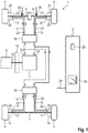
- the Fig. 1 shows a schematic representation of an embodiment of a drive unit of a vehicle, in particular a self-propelled agricultural harvesting machine 1 with an electronic control device 2 according to the invention for the hydraulic drive units of the travel drive.
- the harvesting machine 1 has a frame (not shown) or a self-supporting chassis which is supported on front ground engagement means 3, 4 and rear ground engagement means 5, 6, which are in engagement with the ground and are designed as wheels.
- the ground engagement means 3, 4, 5, 6 transmit the drive torques acting on them to the ground.
- the front ground engaging means 3, 4 of a harvesting machine 1 can also each consist of a crawler track (not shown), with one running gear corresponding to a ground engaging means 3, 4 at the front. Due to the different weight distribution of the vehicle on the front 7 and rear axles 8, there is also different traction on the front and rear ground engaging means 3, 4, 5, 6.
- the ground engaging means 3, 4 arranged on the front axle 7 are less traction-critical due to the greater wheel load than the drive wheels arranged on the rear steering axle 8.
- the drive unit comprises a main engine 9 in the form of an internal combustion engine, preferably a diesel engine, which drives various crop processing and conveying devices and the drive of the harvesting machine 1.
- the drive of the travel drives takes place via a shaft 10 of the main motor 9 to the hydraulic pump 11, the fluid displacement of which by a swivel plate (not shown) provides mechanical power in converts hydraulic power (pressure x volume flow), whereby the swivel plate can be controlled.
- the control of the hydraulic pump 11 will not be discussed in more detail here because it is assumed to be known.
- a transmission 12 (shown in dashed lines) can also be located between the main motor 9 and the hydraulic pump 11.
- the hydraulic pump 11 has an outlet 13 and an inlet 14.
- the outlet 13 is connected as an inlet via hydraulic lines 15 and a distributor 16 to the inlet 17 of the hydraulic motors 18, 19, 20, 21, while the outlet 22 of the hydraulic motors 18, 19, 20, 21 via hydraulic lines 23 as a return to the inlet 14 the hydraulic pump 11 is fed back.
- Two of the hydraulic motors 18, 19 are arranged on the front axle 7, each hydraulic motor 18, 19 driving one of the front wheels via a drive shaft 24, 25.
- Two further hydraulic motors 20, 21 are located on the rear axle 8 and each drive a rear wheel via a drive shaft 26, 27.
- the control device 2 is connected to a plurality of sensors arranged in the harvesting machine 1 in order to receive their signals 28 for processing.
- One of these sensors relates to a steering angle sensor 29, which detects the current steering angle 33 on the rear axle 8.
- the steerable rear axle 8 is divided into two parts in the illustrated embodiment and designed as a pendulum axle.
- values for a specification of the drive torque are calculated, from which at least one power curve 30 for the hydraulic motors 18, 19, 20, 21 is determined.
- the absorption volume for the hydraulic motors 18, 19, 20, 21 is specified from the power curve 30 and the drive torque of the ground engagement means 3, 4, 5, 6 is set by means of the absorption volume.
- the control of the specified absorption volume takes place in a manner known per se by regulating a hydraulic adjusting motor (not shown) or a swivel plate of the hydraulic motors 18, 19, 20, 21. Transferring movement from the control device 2 to the swivel plate, wherein the adjusting device can preferably consist of an electromechanical actuator.
- the swivel plate of the hydraulic motors 18, 19, 20, 21 is thus controlled via the power curve 30 contained in the control device 2, which results in a controllable absorption volume.
- the control device 2 determines the values for specifying the drive torque as a function of the steering angle 33.
- the control device 2 calculates the specification of the drive torque in such a way that the ratio between the drive torque transmitted to the ground by the ground engagement means 3, 4 of the front axle 7 and the drive torque transmitted to the ground by the ground engagement means 5, 6 of the rear axle 8 is regulated as a function of the steering angle 33.
- control device 2 is set up in such a way that, as the steering angle 33 deviates from 0 degrees for the ground engaging means 5, 6 arranged on the rear axle 8, it also determines an increasingly increased specification of the drive torque.
- a steering angle 33 of 0 degrees corresponds to a steering angle 33 provided for driving in the forward direction.
- the specification of the drive torque for the ground engagement means 3, 4 arranged on the front axle 7 is contrary to the specification of the drive torque for those arranged on the rear axle 8 Ground engaging means 5, 6.
- the determined specification of the drive torque for the ground engaging means 3, 4 arranged on the front axle 7 becomes smaller with increasing deviation of the steering angle 33 from 0 degrees.
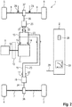
- Fig. 2 shows an alternative embodiment of the drive unit of the vehicle with an electronic control device 2 according to the invention in a schematic representation. Descriptions and information on the traction drive and the control device 2 are identical in the Fig. 1 are included in Fig. 2 not repeated and are marked with the same reference numerals where elements match.
- the main difference to the drive from the Fig. 1 is that the in Fig. 2 All-wheel drive shown comprises only two hydraulic motors 19, 20, each of which drives a differential gear 36, 37 with a drive shaft 34, 35.
- the first hydraulic motor 19 drives the two front ground engagement means 3, 4 via a first drive shaft 34 and a first self-locking differential gear 36.
- the second hydraulic motor 20 drives the two rear ground engagement means 5, 6 via a second drive shaft 35 and a second self-locking differential gear 37.
- Fig. 3 shows an exemplary curve of the absorption volume 31 of the hydraulic motors 18, 19 assigned to the ground engagement means 3, 4 of the front axle 7 and of the absorption volume 32 of the hydraulic motors 20, 21 assigned to the ground engagement means 5, 6 of the rear axle 8 as a function of the steering angle 33.
- the specification max L corresponds to the maximum adjustable steering angle 33 for a left turn and max R the maximum adjustable steering angle 33 for a right turn.
- Fig. 3 shows, at a steering angle 33 of 0 degrees, the hydraulic motors 18, 19 assigned to the front axle 7 are assigned a larger amount of absorption volume 31 than the hydraulic motors 20, 21 assigned to the rear axle 8.
- An increase in the steering angle 33 now leads to a stepless change in the ratio between the converted absorption volume 31 from the hydraulic motors 18, 19 assigned to the front axle 7 and the converted absorption volume 32 from the hydraulic motors 20, 21 assigned to the rear axle 8.
- the absorption volume 32 converted by the hydraulic motors 20, 21 of the rear axle 8 increases, while the absorption volume 31 converted by the hydraulic motors 18, 19 of the front axle 7 becomes smaller.
- the hydraulic motors 20, 21 used to drive the ground engagement means 5, 6 of the rear axle 8 are assigned a larger amount of absorption volume 32 than the hydraulic motors 24 used to drive the ground engagement means 3, 4 of the front axle 7 , 25, so that the ground engagement means 5, 6 arranged on the rear axle 8 transmit a greater drive torque to the ground than the ground engagement means 3, 4 arranged on the front axle 7.
- a threshold value is preferably in a range of 5-10 degrees, more preferably in a range of 10-15 degrees, more preferably in a range of 15-20 degrees.
- the total absorption volume 31, 32 converted by the hydraulic motors 18, 19, 20, 21 used for the drive can also increase or decrease, with the proportional allocation to the hydraulic motors used to drive the ground engagement means 3, 4 of the front axle 7 18, 19 and to the hydraulic motors 20, 21 used to drive the ground engagement means 5, 6 of the rear axle 8 as a function of the steering angle 33.
- the device disclosed may be a further component of the electronic control device 2 for the drive unit of the vehicle equipped according to the invention.
Landscapes
- Engineering & Computer Science (AREA)
- Chemical & Material Sciences (AREA)
- Combustion & Propulsion (AREA)
- Transportation (AREA)
- Mechanical Engineering (AREA)
- Automation & Control Theory (AREA)
- Non-Deflectable Wheels, Steering Of Trailers, Or Other Steering (AREA)
- Arrangement And Driving Of Transmission Devices (AREA)
- Guiding Agricultural Machines (AREA)
Applications Claiming Priority (1)
| Application Number | Priority Date | Filing Date | Title |
|---|---|---|---|
| DE102020112948.3A DE102020112948A1 (de) | 2020-05-13 | 2020-05-13 | Lenkwinkelabhängige Drehmomentverteilung |
Publications (1)
| Publication Number | Publication Date |
|---|---|
| EP3909799A1 true EP3909799A1 (fr) | 2021-11-17 |
Family
ID=74871277
Family Applications (1)
| Application Number | Title | Priority Date | Filing Date |
|---|---|---|---|
| EP21162066.1A Pending EP3909799A1 (fr) | 2020-05-13 | 2021-03-11 | Répartition du couple en fonction de l'angle de direction |
Country Status (2)
| Country | Link |
|---|---|
| EP (1) | EP3909799A1 (fr) |
| DE (1) | DE102020112948A1 (fr) |
Citations (5)
| Publication number | Priority date | Publication date | Assignee | Title |
|---|---|---|---|---|
| EP0314389A2 (fr) * | 1987-10-23 | 1989-05-03 | Fuji Jukogyo Kabushiki Kaisha | Système de transmission pour véhicule à quatre roues motrices |
| EP1364824A2 (fr) * | 2002-05-20 | 2003-11-26 | Deere & Company | Dispositif de commande d'un différentiel central |
| DE102007030168A1 (de) | 2007-06-27 | 2009-01-08 | Claas Selbstfahrende Erntemaschinen Gmbh | Elektronische Steuerung für die Antriebseinheit eines Fahrzeugs |
| DE102010009665A1 (de) * | 2010-02-27 | 2011-09-01 | Bayerische Motoren Werke Aktiengesellschaft | Verfahren zur Steuerung des Drehmoments eines Antriebsmotors in einem Kraftfahrzeug |
| EP3689660A1 (fr) * | 2019-01-30 | 2020-08-05 | Mazda Motor Corporation | Système de véhicule |
-
2020
- 2020-05-13 DE DE102020112948.3A patent/DE102020112948A1/de active Pending
-
2021
- 2021-03-11 EP EP21162066.1A patent/EP3909799A1/fr active Pending
Patent Citations (5)
| Publication number | Priority date | Publication date | Assignee | Title |
|---|---|---|---|---|
| EP0314389A2 (fr) * | 1987-10-23 | 1989-05-03 | Fuji Jukogyo Kabushiki Kaisha | Système de transmission pour véhicule à quatre roues motrices |
| EP1364824A2 (fr) * | 2002-05-20 | 2003-11-26 | Deere & Company | Dispositif de commande d'un différentiel central |
| DE102007030168A1 (de) | 2007-06-27 | 2009-01-08 | Claas Selbstfahrende Erntemaschinen Gmbh | Elektronische Steuerung für die Antriebseinheit eines Fahrzeugs |
| DE102010009665A1 (de) * | 2010-02-27 | 2011-09-01 | Bayerische Motoren Werke Aktiengesellschaft | Verfahren zur Steuerung des Drehmoments eines Antriebsmotors in einem Kraftfahrzeug |
| EP3689660A1 (fr) * | 2019-01-30 | 2020-08-05 | Mazda Motor Corporation | Système de véhicule |
Also Published As
| Publication number | Publication date |
|---|---|
| DE102020112948A1 (de) | 2021-11-18 |
Similar Documents
| Publication | Publication Date | Title |
|---|---|---|
| EP3100934B1 (fr) | Engin agricole | |
| DE19637193B4 (de) | Verfahren zum Beeinflussen des Gierverhaltens eines Fahrzeugs | |
| DE3427725C2 (fr) | ||
| DE19603427B4 (de) | Antriebsschlupfregelung für ein Kraftfahrzeug mit Allradantrieb | |
| DE4112906C2 (de) | Steuer- und Regelvorrichtung für ein Kraftfahrzeug zur Begrenzung der Differentialkraft | |
| DE3840397A1 (de) | Anordnung zum steuern der verteilung der antriebskraft in einem fahrzeug mit vierradantrieb | |
| DE102013011883A1 (de) | Verfahren zum Betreiben der Lenkung eines Kranftfahrzeugs | |
| EP2759438B1 (fr) | Mécanisme d'entraînement de véhicule doté d'un entraînement auxiliaire hydrostatique, véhicule avec un tel mécanisme d'entraînement et procédé d'opération pour un tel mécanisme d'entraînement | |
| EP3083314B1 (fr) | Unité différentielle d'un véhicule automobile et son procédé de commande | |
| EP2995533B1 (fr) | Chenille orientable | |
| WO1989010279A1 (fr) | Tracteur toutes roues motrices | |
| DE19748086A1 (de) | Fahrzeug mit Vierradantrieb | |
| EP2930086A2 (fr) | Moissonneuse automotrice | |
| DE19539670B4 (de) | Drehmomentverteilungs-Steuersystem | |
| EP1648729B1 (fr) | Dispositif de commande pour vehicule automobile a quatre roues motrices au moins de façon intermittente | |
| EP1031494A1 (fr) | Système de contrôle pour véhicules à chenilles | |
| EP3909799A1 (fr) | Répartition du couple en fonction de l'angle de direction | |
| EP0331203B1 (fr) | Méthode de commande du braquage simultané des roues arrière d'un véhicule en fonction du braquage des roues avant | |
| EP1185807B1 (fr) | Systeme d'entrainement hydrostatique | |
| EP1364824A2 (fr) | Dispositif de commande d'un différentiel central | |
| WO2017211338A1 (fr) | Procédé de commande d'un véhicule et véhicule pour mettre ledit procédé en oeuvre | |
| DE102010021624A1 (de) | Hydrostatischer Fahrantrieb | |
| EP3901004B1 (fr) | Compensation de dérive | |
| EP3628524B1 (fr) | Système d'entraînement à fonction différentielle bloquant variable | |
| EP1462292B1 (fr) | Système de contrôle de distribution variable du couple |
Legal Events
| Date | Code | Title | Description |
|---|---|---|---|
| PUAI | Public reference made under article 153(3) epc to a published international application that has entered the european phase |
Free format text: ORIGINAL CODE: 0009012 |
|
| STAA | Information on the status of an ep patent application or granted ep patent |
Free format text: STATUS: THE APPLICATION HAS BEEN PUBLISHED |
|
| AK | Designated contracting states |
Kind code of ref document: A1 Designated state(s): AL AT BE BG CH CY CZ DE DK EE ES FI FR GB GR HR HU IE IS IT LI LT LU LV MC MK MT NL NO PL PT RO RS SE SI SK SM TR |
|
| B565 | Issuance of search results under rule 164(2) epc |
Effective date: 20210910 |
|
| STAA | Information on the status of an ep patent application or granted ep patent |
Free format text: STATUS: REQUEST FOR EXAMINATION WAS MADE |
|
| 17P | Request for examination filed |
Effective date: 20220517 |
|
| RBV | Designated contracting states (corrected) |
Designated state(s): AL AT BE BG CH CY CZ DE DK EE ES FI FR GB GR HR HU IE IS IT LI LT LU LV MC MK MT NL NO PL PT RO RS SE SI SK SM TR |
|
| P01 | Opt-out of the competence of the unified patent court (upc) registered |
Effective date: 20230516 |
|
| STAA | Information on the status of an ep patent application or granted ep patent |
Free format text: STATUS: EXAMINATION IS IN PROGRESS |
|
| 17Q | First examination report despatched |
Effective date: 20231109 |