EP3909754A1 - Radstern aus zusammengesetzten speichenelementen und dessen anbindung an das felgenbett - Google Patents
Radstern aus zusammengesetzten speichenelementen und dessen anbindung an das felgenbett Download PDFInfo
- Publication number
- EP3909754A1 EP3909754A1 EP21176115.0A EP21176115A EP3909754A1 EP 3909754 A1 EP3909754 A1 EP 3909754A1 EP 21176115 A EP21176115 A EP 21176115A EP 3909754 A1 EP3909754 A1 EP 3909754A1
- Authority
- EP
- European Patent Office
- Prior art keywords
- rim
- spoke
- hub
- spoke elements
- wheel
- Prior art date
- Legal status (The legal status is an assumption and is not a legal conclusion. Google has not performed a legal analysis and makes no representation as to the accuracy of the status listed.)
- Withdrawn
Links
- 239000002131 composite material Substances 0.000 title claims description 9
- 241000239290 Araneae Species 0.000 title description 12
- 238000004519 manufacturing process Methods 0.000 claims abstract description 12
- 239000000835 fiber Substances 0.000 claims description 26
- 239000004753 textile Substances 0.000 claims description 22
- 239000000463 material Substances 0.000 claims description 16
- 238000000034 method Methods 0.000 claims description 12
- 238000009954 braiding Methods 0.000 claims description 9
- 230000002787 reinforcement Effects 0.000 claims description 6
- 238000007596 consolidation process Methods 0.000 claims description 5
- 239000011159 matrix material Substances 0.000 claims description 4
- 210000000078 claw Anatomy 0.000 claims description 2
- 238000003780 insertion Methods 0.000 claims 1
- 230000037431 insertion Effects 0.000 claims 1
- 229910052751 metal Inorganic materials 0.000 description 12
- 239000002184 metal Substances 0.000 description 12
- 238000010276 construction Methods 0.000 description 11
- 238000013461 design Methods 0.000 description 9
- 238000000465 moulding Methods 0.000 description 8
- 230000005540 biological transmission Effects 0.000 description 4
- 229910000831 Steel Inorganic materials 0.000 description 3
- 229910052782 aluminium Inorganic materials 0.000 description 3
- XAGFODPZIPBFFR-UHFFFAOYSA-N aluminium Chemical compound [Al] XAGFODPZIPBFFR-UHFFFAOYSA-N 0.000 description 3
- 238000005304 joining Methods 0.000 description 3
- 239000010959 steel Substances 0.000 description 3
- 229920002430 Fibre-reinforced plastic Polymers 0.000 description 2
- FYYHWMGAXLPEAU-UHFFFAOYSA-N Magnesium Chemical compound [Mg] FYYHWMGAXLPEAU-UHFFFAOYSA-N 0.000 description 2
- 230000015572 biosynthetic process Effects 0.000 description 2
- 238000005516 engineering process Methods 0.000 description 2
- 239000011151 fibre-reinforced plastic Substances 0.000 description 2
- 238000005755 formation reaction Methods 0.000 description 2
- 229910052749 magnesium Inorganic materials 0.000 description 2
- 239000011777 magnesium Substances 0.000 description 2
- 239000004033 plastic Substances 0.000 description 2
- 229920003023 plastic Polymers 0.000 description 2
- 238000012805 post-processing Methods 0.000 description 2
- 229920000049 Carbon (fiber) Polymers 0.000 description 1
- 229910045601 alloy Inorganic materials 0.000 description 1
- 239000000956 alloy Substances 0.000 description 1
- 229920006231 aramid fiber Polymers 0.000 description 1
- 239000004917 carbon fiber Substances 0.000 description 1
- 239000000919 ceramic Substances 0.000 description 1
- 230000001419 dependent effect Effects 0.000 description 1
- 238000011161 development Methods 0.000 description 1
- 238000007598 dipping method Methods 0.000 description 1
- 239000000945 filler Substances 0.000 description 1
- 239000003365 glass fiber Substances 0.000 description 1
- 238000002844 melting Methods 0.000 description 1
- 230000008018 melting Effects 0.000 description 1
- 229910001092 metal group alloy Inorganic materials 0.000 description 1
- 150000002739 metals Chemical class 0.000 description 1
- VNWKTOKETHGBQD-UHFFFAOYSA-N methane Chemical compound C VNWKTOKETHGBQD-UHFFFAOYSA-N 0.000 description 1
- 238000003825 pressing Methods 0.000 description 1
- 239000012779 reinforcing material Substances 0.000 description 1
- 239000011347 resin Substances 0.000 description 1
- 229920005989 resin Polymers 0.000 description 1
- 238000007493 shaping process Methods 0.000 description 1
- 239000011343 solid material Substances 0.000 description 1
- 238000003892 spreading Methods 0.000 description 1
- 238000009728 tailored fiber placement Methods 0.000 description 1
- 238000012546 transfer Methods 0.000 description 1
Images






Classifications
-
- B—PERFORMING OPERATIONS; TRANSPORTING
- B29—WORKING OF PLASTICS; WORKING OF SUBSTANCES IN A PLASTIC STATE IN GENERAL
- B29C—SHAPING OR JOINING OF PLASTICS; SHAPING OF MATERIAL IN A PLASTIC STATE, NOT OTHERWISE PROVIDED FOR; AFTER-TREATMENT OF THE SHAPED PRODUCTS, e.g. REPAIRING
- B29C70/00—Shaping composites, i.e. plastics material comprising reinforcements, fillers or preformed parts, e.g. inserts
- B29C70/04—Shaping composites, i.e. plastics material comprising reinforcements, fillers or preformed parts, e.g. inserts comprising reinforcements only, e.g. self-reinforcing plastics
- B29C70/28—Shaping operations therefor
- B29C70/30—Shaping by lay-up, i.e. applying fibres, tape or broadsheet on a mould, former or core; Shaping by spray-up, i.e. spraying of fibres on a mould, former or core
- B29C70/302—Details of the edges of fibre composites, e.g. edge finishing or means to avoid delamination
-
- B—PERFORMING OPERATIONS; TRANSPORTING
- B29—WORKING OF PLASTICS; WORKING OF SUBSTANCES IN A PLASTIC STATE IN GENERAL
- B29C—SHAPING OR JOINING OF PLASTICS; SHAPING OF MATERIAL IN A PLASTIC STATE, NOT OTHERWISE PROVIDED FOR; AFTER-TREATMENT OF THE SHAPED PRODUCTS, e.g. REPAIRING
- B29C70/00—Shaping composites, i.e. plastics material comprising reinforcements, fillers or preformed parts, e.g. inserts
- B29C70/04—Shaping composites, i.e. plastics material comprising reinforcements, fillers or preformed parts, e.g. inserts comprising reinforcements only, e.g. self-reinforcing plastics
- B29C70/06—Fibrous reinforcements only
-
- B—PERFORMING OPERATIONS; TRANSPORTING
- B29—WORKING OF PLASTICS; WORKING OF SUBSTANCES IN A PLASTIC STATE IN GENERAL
- B29C—SHAPING OR JOINING OF PLASTICS; SHAPING OF MATERIAL IN A PLASTIC STATE, NOT OTHERWISE PROVIDED FOR; AFTER-TREATMENT OF THE SHAPED PRODUCTS, e.g. REPAIRING
- B29C70/00—Shaping composites, i.e. plastics material comprising reinforcements, fillers or preformed parts, e.g. inserts
- B29C70/04—Shaping composites, i.e. plastics material comprising reinforcements, fillers or preformed parts, e.g. inserts comprising reinforcements only, e.g. self-reinforcing plastics
- B29C70/28—Shaping operations therefor
- B29C70/30—Shaping by lay-up, i.e. applying fibres, tape or broadsheet on a mould, former or core; Shaping by spray-up, i.e. spraying of fibres on a mould, former or core
- B29C70/34—Shaping by lay-up, i.e. applying fibres, tape or broadsheet on a mould, former or core; Shaping by spray-up, i.e. spraying of fibres on a mould, former or core and shaping or impregnating by compression, i.e. combined with compressing after the lay-up operation
- B29C70/345—Shaping by lay-up, i.e. applying fibres, tape or broadsheet on a mould, former or core; Shaping by spray-up, i.e. spraying of fibres on a mould, former or core and shaping or impregnating by compression, i.e. combined with compressing after the lay-up operation using matched moulds
-
- B—PERFORMING OPERATIONS; TRANSPORTING
- B29—WORKING OF PLASTICS; WORKING OF SUBSTANCES IN A PLASTIC STATE IN GENERAL
- B29D—PRODUCING PARTICULAR ARTICLES FROM PLASTICS OR FROM SUBSTANCES IN A PLASTIC STATE
- B29D99/00—Subject matter not provided for in other groups of this subclass
- B29D99/0032—Producing rolling bodies, e.g. rollers, wheels, pulleys or pinions
-
- B—PERFORMING OPERATIONS; TRANSPORTING
- B60—VEHICLES IN GENERAL
- B60B—VEHICLE WHEELS; CASTORS; AXLES FOR WHEELS OR CASTORS; INCREASING WHEEL ADHESION
- B60B1/00—Spoked wheels; Spokes thereof
- B60B1/06—Wheels with compression spokes
- B60B1/14—Attaching spokes to rim or hub
-
- B—PERFORMING OPERATIONS; TRANSPORTING
- B60—VEHICLES IN GENERAL
- B60B—VEHICLE WHEELS; CASTORS; AXLES FOR WHEELS OR CASTORS; INCREASING WHEEL ADHESION
- B60B3/00—Disc wheels, i.e. wheels with load-supporting disc body
- B60B3/04—Disc wheels, i.e. wheels with load-supporting disc body with a single disc body not integral with rim, i.e. disc body and rim being manufactured independently and then permanently attached to each other in a second step, e.g. by welding
- B60B3/041—Disc wheels, i.e. wheels with load-supporting disc body with a single disc body not integral with rim, i.e. disc body and rim being manufactured independently and then permanently attached to each other in a second step, e.g. by welding characterised by the attachment of rim to wheel disc
-
- B—PERFORMING OPERATIONS; TRANSPORTING
- B60—VEHICLES IN GENERAL
- B60B—VEHICLE WHEELS; CASTORS; AXLES FOR WHEELS OR CASTORS; INCREASING WHEEL ADHESION
- B60B3/00—Disc wheels, i.e. wheels with load-supporting disc body
- B60B3/10—Disc wheels, i.e. wheels with load-supporting disc body apertured to simulate spoked wheels
-
- B—PERFORMING OPERATIONS; TRANSPORTING
- B60—VEHICLES IN GENERAL
- B60B—VEHICLE WHEELS; CASTORS; AXLES FOR WHEELS OR CASTORS; INCREASING WHEEL ADHESION
- B60B5/00—Wheels, spokes, disc bodies, rims, hubs, wholly or predominantly made of non-metallic material
- B60B5/02—Wheels, spokes, disc bodies, rims, hubs, wholly or predominantly made of non-metallic material made of synthetic material
-
- B—PERFORMING OPERATIONS; TRANSPORTING
- B29—WORKING OF PLASTICS; WORKING OF SUBSTANCES IN A PLASTIC STATE IN GENERAL
- B29K—INDEXING SCHEME ASSOCIATED WITH SUBCLASSES B29B, B29C OR B29D, RELATING TO MOULDING MATERIALS OR TO MATERIALS FOR MOULDS, REINFORCEMENTS, FILLERS OR PREFORMED PARTS, e.g. INSERTS
- B29K2105/00—Condition, form or state of moulded material or of the material to be shaped
- B29K2105/25—Solid
- B29K2105/253—Preform
-
- B—PERFORMING OPERATIONS; TRANSPORTING
- B29—WORKING OF PLASTICS; WORKING OF SUBSTANCES IN A PLASTIC STATE IN GENERAL
- B29L—INDEXING SCHEME ASSOCIATED WITH SUBCLASS B29C, RELATING TO PARTICULAR ARTICLES
- B29L2031/00—Other particular articles
- B29L2031/32—Wheels, pinions, pulleys, castors or rollers, Rims
-
- B—PERFORMING OPERATIONS; TRANSPORTING
- B29—WORKING OF PLASTICS; WORKING OF SUBSTANCES IN A PLASTIC STATE IN GENERAL
- B29L—INDEXING SCHEME ASSOCIATED WITH SUBCLASS B29C, RELATING TO PARTICULAR ARTICLES
- B29L2031/00—Other particular articles
- B29L2031/32—Wheels, pinions, pulleys, castors or rollers, Rims
- B29L2031/322—Wheels, pinions, pulleys, castors or rollers, Rims made wholly of plastics
-
- B—PERFORMING OPERATIONS; TRANSPORTING
- B60—VEHICLES IN GENERAL
- B60B—VEHICLE WHEELS; CASTORS; AXLES FOR WHEELS OR CASTORS; INCREASING WHEEL ADHESION
- B60B2310/00—Manufacturing methods
- B60B2310/20—Shaping
- B60B2310/204—Shaping by moulding, e.g. injection moulding, i.e. casting of plastics material
-
- B—PERFORMING OPERATIONS; TRANSPORTING
- B60—VEHICLES IN GENERAL
- B60B—VEHICLE WHEELS; CASTORS; AXLES FOR WHEELS OR CASTORS; INCREASING WHEEL ADHESION
- B60B2310/00—Manufacturing methods
- B60B2310/20—Shaping
- B60B2310/241—Shaping by weaving or knitting of fibers
-
- B—PERFORMING OPERATIONS; TRANSPORTING
- B60—VEHICLES IN GENERAL
- B60B—VEHICLE WHEELS; CASTORS; AXLES FOR WHEELS OR CASTORS; INCREASING WHEEL ADHESION
- B60B2360/00—Materials; Physical forms thereof
- B60B2360/30—Synthetic materials
- B60B2360/34—Reinforced plastics
- B60B2360/341—Reinforced plastics with fibres
-
- B—PERFORMING OPERATIONS; TRANSPORTING
- B60—VEHICLES IN GENERAL
- B60B—VEHICLE WHEELS; CASTORS; AXLES FOR WHEELS OR CASTORS; INCREASING WHEEL ADHESION
- B60B2900/00—Purpose of invention
- B60B2900/10—Reduction of
- B60B2900/111—Weight
-
- B—PERFORMING OPERATIONS; TRANSPORTING
- B60—VEHICLES IN GENERAL
- B60B—VEHICLE WHEELS; CASTORS; AXLES FOR WHEELS OR CASTORS; INCREASING WHEEL ADHESION
- B60B2900/00—Purpose of invention
- B60B2900/30—Increase in
- B60B2900/311—Rigidity or stiffness
-
- Y—GENERAL TAGGING OF NEW TECHNOLOGICAL DEVELOPMENTS; GENERAL TAGGING OF CROSS-SECTIONAL TECHNOLOGIES SPANNING OVER SEVERAL SECTIONS OF THE IPC; TECHNICAL SUBJECTS COVERED BY FORMER USPC CROSS-REFERENCE ART COLLECTIONS [XRACs] AND DIGESTS
- Y02—TECHNOLOGIES OR APPLICATIONS FOR MITIGATION OR ADAPTATION AGAINST CLIMATE CHANGE
- Y02T—CLIMATE CHANGE MITIGATION TECHNOLOGIES RELATED TO TRANSPORTATION
- Y02T10/00—Road transport of goods or passengers
- Y02T10/80—Technologies aiming to reduce greenhouse gasses emissions common to all road transportation technologies
- Y02T10/86—Optimisation of rolling resistance, e.g. weight reduction
Definitions
- the subject of the present patent application is a wheel, preferably for motor vehicles, with spokes, the spokes in the hub area directly adjoining one another in the circumferential direction and being fixed in the axial direction by two hub parts.
- the spokes are positively attached to the inside (the side facing the axle) of the rim base.
- the DE 102010010512A1 provides a wheel spider that is non-positively and / or positively connected to the rim base.
- the grid consists of fiber composite material or metal.
- the disadvantage is that the wheel spider has to be prefabricated and cannot be produced in connection with the production of the entire wheel.
- the power transmission between the metal and the fiber composite material of the rim is problematic.
- the different expansion coefficients of the materials can contribute to damage.
- a full-surface wheel disc is concealed by spokes placed in front of it.
- these spokes are designed as loop-like structures in the hub area directly abut one another and also run together in the space between the hub and the rim.
- the attachment in the hub area is carried out by means of a union ring and screw connections.
- These spokes are fastened to the rim by means of a screw connection in a direction that is essentially parallel to the axis.
- the spokes are used for decorative purposes only and do not have a load-bearing function. Accordingly, it is provided that they are made of plastic material and that the connection to the wheel is releasable.
- the function of the spoke construction as a mere attachment for a disc wheel increases the weight of the wheel.
- the task is thus to propose a wheel construction that overcomes the restrictions in the design freedom of the wheel spider and still meets the weight and strength requirements of modern automobile construction.
- a method for producing such a wheel structure is to be specified.
- the object is achieved with the wheel according to claim 1.
- a method for producing the wheel according to the invention from fiber composite material is disclosed in claim 9.
- Advantageous embodiments are shown in the dependent claims that refer back.
- the wheel according to the invention has a rim with a rim well and rim flanges, a hub and at least three spoke elements which form spokes between the hub and the rim.
- the spoke elements are positively or positively and cohesively attached to the inside of the rim.
- the spoke elements rest against one another in the circumferential direction and are supported against one another. For this purpose, they have flat abutment surfaces on which they rest against one another.
- the spoke elements are preferably fixed by two hub parts between which they are inserted. These hub parts lie opposite one another on the axis, the spoke element ends being arranged between them.
- the hub parts preferably touch the spoke element ends directly and hold them.
- the hub parts act as force introduction elements and transfer axial force components that act on the wheel to the axle and vice versa. They are preferably made of fiber-reinforced material (preferably identical to the material of the rim or the spoke elements). Preferred embodiments provide hub parts made of metal, preferably steel, aluminum or magnesium or suitable alloys from the prior art. The hub parts preferably have screw openings for the fastening screws of the wheel. Furthermore, the hub parts or one of the hub parts also have a central axle opening if the design of the wheel requires one. The hub parts are preferably designed in the form of a flange and lie on top of one another flat opposite.
- Another preferred embodiment provides pegs on one or both hub parts which engage between the spokes like claws and reach up to the opposite hub part or the pegs of the opposite hub part.
- the pins advantageously support the transmission of radial forces to the spokes.
- the pins of the two hub parts can also be arranged alternately. Preferably, there remains a small distance between the pins of opposite hub parts or between the pins of one and the other hub part in order to avoid that the clamping force applied by the screws during the assembly of the wheel is completely absorbed by the pins. This force should preferably act on the spoke element ends that are clamped between the two hub parts.
- the pins have threaded bores which correspond to screw holes in the opposite hub part.
- the hub parts can hold the ends of the spoke elements without having to enter into a material connection with them.
- the spoke elements contain molded bodies and are provided in an unconsolidated state during manufacture, since in this way the cohesion of the hub area of the wheel can be ensured.
- the hub area is understood to mean the area of the spoke elements which is located between the geometric wheel axis and the radially outer ends of the hub parts, that is to say the spoke element sections covered by the hub parts in the front and rear view of the wheel.
- the spokes of the wheel according to the invention take over the transmission of the forces occurring during vehicle operation. It is therefore not a question of purely decorative elements.
- the use of the wheels according to the invention is intended in particular for cars, trucks, buses and other commercial vehicles.
- the abutment surfaces of the spoke elements are contoured in such a way that they mesh with one another in an ideal manner.
- the spoke elements have, for example, elevations on one side (seen in the direction of rotation) and depressions on the other side. The elevations and depressions of adjacent spoke elements then interlock in a form-fitting manner.
- Each spoke element consists of one or more textile strands or layers of textile strands.
- the fiber reinforcements in the textile strands are preferably unidirectional, directed parallel to the longitudinal axis of the spoke or from the hub to the rim. Layers in which unidirectional fibers are held together flatly are also preferred. Here, too, the layers or the unidirectional fibers of the layers are directed parallel to the longitudinal axis of the spoke or from the hub to the rim.
- the superimposed layers are preferably stitched together (embroidered). In a preferred embodiment it is provided to cover the textile strands with one or more layers of textile in order to hold them together in the unconsolidated state and to offer better protection against lateral loads in the consolidated state.
- the layers are in the axial direction ( Figure 4b ) or layered or arranged against one another in the circumferential direction.
- the orientation of the layers is particularly advantageously chosen so that when the layers are later divided at one spoke end, for example for connection to the rim or for inserting molded bodies, they can be unfolded in layers and no layers have to be divided.
- each spoke element forms a single spoke that extends from the hub to the rim.
- this spoke can already have cross-sectional variations along the longitudinal axis or curvatures.
- the axis along the greatest extent of the spoke is understood as the longitudinal axis of the spoke.
- a spoke element forms two, three, four or more spokes.
- two or more spokes are formed in one spoke element, the textile strands of one spoke splitting in the radial direction and converging with the split textile strands of other spokes ( Fig. 9 ). This can also be done several times, so that grids or rhombus-like structures or other decorative designs are possible.
- molded bodies are inserted into the spoke elements, which are used to specify and fix the desired spoke shape.
- These molded bodies are preferably made of materials that bond very well with the matrix material and / or the fiber reinforcements (for example melting during consolidation or the like).
- the spokes can have any cross-sections that enable a load-appropriate design of the wheel spider; rectangular and / or square cross-sections are preferred. However, round, oval or polygonal cross-sections are also preferred.
- the cross-sections can also vary along the longitudinal axes of the spokes.
- the spoke elements have shaped bodies in their interior in the hub area.
- the molded bodies are completely covered by the fiber-reinforced material of the spokes.
- the shaped bodies extend to the surface (the end of the spoke) at the end facing the axis and transmit bearing forces.
- these shaped bodies are axial Direction of layers of textile strands (front and back of the spoke elements) covered. In the circumferential direction they reach up to the surface of the spoke elements, so that the forces occurring on the abutment surfaces of the spoke elements are absorbed or transmitted by the molded bodies.
- the shaped bodies extend in the axial direction or in the axial and circumferential direction up to the surface of the spoke elements. In this way, the molded bodies can also transmit axial or axial and rotational forces.
- the shaped bodies in the hub area are preferably made of metal (for example steel, aluminum). They can also protrude within the spoke elements beyond the hub area in the direction of the rim and thus achieve an improved power transmission between the hub and the rim.
- the spoke elements are put together to form the wheel spider.
- the spoke elements in the wheel hub area preferably have an axially directed cone or conical surfaces which function as abutment surfaces. They are preferably pressed together and held in the axial direction by clamping disks, which act as hub parts (force introduction elements).
- the abutting surfaces of adjacent spoke elements lie directly on top of one another without any intermediate components.
- intermediate elements which transmit the circumferential forces are located between two adjacent abutment surfaces.
- the intermediate elements are preferably made of metal, but plastics and ceramics are also possible.
- the spoke elements are preferably connected to the rim well via an undercut connection, with the ends of the textile spoke preform being positively connected to the rim well by braiding (preforming the rim well using the braiding process).
- Preferred embodiments provide to divide the textile strands that form the spoke elements in the rim area and to arrange them in such a way that they follow the rim shape in the axial direction or in the circumferential direction (in both directions of rotation of the wheel) and thus form a form-fitting connection.
- the spoke elements have the necessary openings for the fastening screws, which correspond to the relevant openings in the hub parts. These openings are created by appropriate braiding during the production of the textile layers or by piercing a prepared spoke element in an unconsolidated state, the fibers preferably remaining intact. This is achieved in that the openings are not punched, but are advantageously created by means of a mandrel by displacing the fiber layers. Should moldings in the hub area of the If spoke elements are used, these advantageously already have the necessary openings for the screw holes.
- the openings for the fastening screws are preferably generated by means of CNC post-processing.
- the wheel according to the invention preferably consists entirely of fiber composite material.
- This is preferably a resin matrix with carbon fiber, glass fiber, metal or aramid fiber reinforcement.
- Further preferred embodiments are mixed forms with metal spoke elements and a rim made of fiber-reinforced material or fiber-reinforced spokes which are connected to a metal rim.
- a wheel construction made entirely of metal is also possible. Suitable metals are known from the prior art (steel, aluminum, magnesium, light metal alloys).
- the wheel construction according to the invention advantageously does not require any CNC post-processing. It realizes the high mass savings potential of the wheel spider while complying with the strength requirements set in automotive engineering.
- the wheel construction according to the invention offers a high degree of design freedom for spoked wheels.
- the method for producing the wheel construction according to the invention from fiber-reinforced material provides that the individual spoke elements are prefabricated from fiber layers and provided in the unconsolidated state.
- the spoke elements are inserted into a molding tool in such a way that they touch one another in the hub area in the circumferential direction.
- the molding tool is closed, with the spoke ends, which are to establish the connection to the rim, remaining exposed.
- these are axially divided into two parts and the parts are fitted axially in opposite directions into the shape of the rim well.
- the rim base is then produced by braiding, whereby a form fit of the spoke ends to the rim base is achieved.
- the fiber layers of the spoke ends are divided parallel to the axis, so that the ends are folded in and against the direction of rotation.
- the rim is then braided over to produce the rim.
- the rim and spokes can be soaked and consolidated with matrix material.
- the front and rear hub parts are attached to the hub to axially stabilize the spokes.
- the hub parts are inserted into the mold and hold the spoke elements when they are braided over. They are already integrated into the wheel in the course of consolidation.
- spoke elements consist of fiber-reinforced material that is already partially or completely preconsolidated.
- the spoke elements are then inserted into the mold and braided over with the reinforcement material of the rim bed, which is then consolidated.
- Hybrid wheels, in which the spoke elements are made of metal, are manufactured in the same way. These are placed in the mold and also braided over at the rim-side ends.
- the wheel spider is made up of individual radial spoke elements (2) which are assembled in the area of the wheel hub.
- the spoke elements assembled via circumferentially directed connecting surfaces form the wheel hub.
- the shaping of the spokes takes place in advance, for example with the help of TFP technology (Tailored Fiber Placement Technology), with which the individual textile strands are built up from several, already dimensioned, fiber layers and thus the unconsolidated final contour can be created taking into account the later spoke shape .
- TFP technology Trimed Fiber Placement Technology
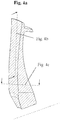
- the layering of the fiber layers can take place in different ways, for example in an axial ( Figure 4b ) Direction or circumferential direction ( Figure 4c ).
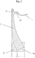
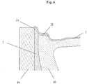
- the spoke ends connected to the rim well (1) have two separate textile strands, which on the one hand run to the rim flange (2a) and on the other hand create the undercut with the rim well (2b) and thus both form a form fit with the rim well.
- the individual fiber strands (7) run as in FIG Figure 4b shown, whereby a gusset area (6) is generated as a result of the spreading of the spoke end, which is filled by additional material before or during the subsequent braiding process.
- the individual spoke elements can only consist of fiber strands or also of an additional filler material (8) which is partially or completely surrounded by fiber strands.
- the spoke elements can have an axially directed cone or conical surface, via which the assembled spoke elements are braced or pressed via force introduction elements.
- the spoke geometry can have any cross-section, a cross-section resolved in the axial direction being preferred.
- the inserted spoke elements are connected to one another by a form fit through their common, circumferentially directed joining zones (9) in the area of the wheel center axis.
- the inner mold mounted which can also have grooves for the spoke elements or is equipped with dipping edges for the grooves of the outer mold half.
- the undercut that occurs as a result of the spoke connection to the rim well can be avoided by using an insert tool or other constructive solutions in order to ensure that the molding tool is removed from the mold.
- the rim well (1) is then formed by braiding around the molding tools that function as braiding core and the folded spoke ends. This means that the spokes are axially integrated into the textile structure of the rim well via a form fit.
- a multi-part external tool is used in the area of the rim well for pressing the textile preform during consolidation.
- the wheel spider and the rim base have a form-fitting and material-locking connection.
- the wheel bolts are received by a front force application element (3a) which is glued to the assembled spoke elements.
- the contact surface of the wheel with the vehicle is also carried out via a rear force application element (3b) that simultaneously takes on the function of centering. Both force introduction elements axially compress the assembled spoke elements and thus keep them under pressure pretension.
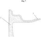
- Embodiment 2 according to Fig. 7 , Fig. 8 The second exemplary embodiment differs from the first in that the individual spoke elements create a form-fitting, undercut connection with the entire deep well of the rim well.
- the end of the spoke (2b) running towards the deep bed is adjusted in such a way that the wall thickness from the rim flange area to the beginning of the rim deep bed is significantly increased and the tab forming the undercut is adapted to the rim deep bed.
- This spoke connection allows the molding tool to be simplified in that no insert tool is required for the undercut formation.
- the spoke ends (2b) encompassing the deep bed are therefore inserted into grooves provided for this purpose after the inner mold has been installed.
- the rim well contour required for the braiding process is therefore formed by the inner and outer mold and the folded spoke ends.
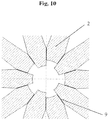
- Embodiment 3 according to Fig. 10 shows schematically the joining zones (9) between the individual spoke elements (2), the radial length of the spoke elements being in Distinguish the direction of the wheel center axis. Every second spoke thus has a kind of recess in the radial direction, after which a stepped wheel hub area is created.
- the force introduction elements (3a, 3b) are designed in such a way that axial formations engage in the recesses and thus a torsion-proof connection between the spoke and force introduction elements is created and rotational forces can be transmitted better.
- the spoke elements (2) are held in the axial direction by the hub parts (3a and 3b).
Landscapes
- Engineering & Computer Science (AREA)
- Mechanical Engineering (AREA)
- Chemical & Material Sciences (AREA)
- Composite Materials (AREA)
- Materials Engineering (AREA)
- Moulding By Coating Moulds (AREA)
- Molds, Cores, And Manufacturing Methods Thereof (AREA)
Abstract
Description
- Gegenstand der vorliegenden Patentanmeldung ist ein Rad, vorzugsweise für Kraftfahrzeuge, mit Speichen, wobei die Speichen im Nabenbereich in Umfangsrichtung unmittelbar aneinander grenzen und in axialer Richtung von zwei Nabenteilen fixiert sind. Auf der Felgenseite sind die Speichen an der Innenseite (der der Achse zugewandten Seite) des Felgenbettes formschlüssig befestigt. Des Weiteren wird ein Verfahren zur Herstellung des erfindungsgemäßen Rades aus Faserverbundwerkstoff offenbart.
- Es existiert eine Vielzahl von Radkonstruktionen für Kraftfahrzeuge, insbesondere PKW. Häufig sind diese Räder aus einem Stück gefertigt. Fortgeschrittene Konstruktionen sehen die Fertigung aus mehreren Einzelteilen vor. Dies ist insbesondere bei den gegenwärtig in der Entwicklung befindlichen Konstruktionen aus faserverstärkten Kunststoffen der Fall. Es wird angestrebt, die Beschränkungen in der Designfreiheit zu überwinden, die aus den technologischen Zwängen der Fertigungsverfahren resultieren. So schlägt die
DE 10 2006 051 867 ein Rad aus faserverstärktem Kunststoff vor, bei dem die Speichen durch Schlaufen aus Verstärkungsmaterial ausgebildet werden, die an der Nabe umgelenkt, der Innenseite der Felge folgend und im Zwischenraum zwischen Nabe und Felge aneinander anliegend ausgeführt sind. Der so entstehende Radstern ist stoffschlüssig mit der ebenfalls aus faserverstärktem Material hergestellten Felge verbunden. Bauartbedingt sind hier keine ausreichenden Variationen des Designs des Radsterns möglich. - Andere bekannte Konstruktionen versuchen diese Nachteile zu überwinden, indem die Öffnungen zwischen den Speichen aus dem faserverstärkten Vollmaterial (bspw. einer Scheibe, die auch konturiert sein kann) herausgefräst werden. Nachteilig wird bei diesem Vorgehen jedoch die Faserverstärkung beschädigt, was zu Festigkeitsverlusten führt.
- Die
DE 102010010512A1 sieht einen Radstern vor, der kraft- und/oder formschlüssig mit dem Felgenbett verbunden ist. Der Rastern besteht aus Faserverbundmaterial oder aus Metall. Nachteilig ist, dass der Radstern vorgefertigt werden muss und nicht in Verbindung mit der Fertigung des gesamten Rades hergestellt werden kann. Bei einem Radstern aus Metall ist die Kraftübertragung zwischen dem Metall und dem Faserverbundmaterial der Felge problematisch. Die unterschiedlichen Ausdehnungskoeffizienten der Materialien können zu Schäden beitragen. - Die
US 7,669,940 B2 geht einen anderen Weg. Hier wird eine vollflächig ausgebildete Radscheibe durch vorgesetzte Speichen kaschiert. Diese Speichen sind in einer bevorzugten Ausführungsform als schleifenartige Gebilde ausgeführt, die im Nabenbereich unmittelbar aneinander anliegen und auch im Zwischenraum zwischen Nabe und Felge gemeinsam verlaufen. Die Befestigung im Nabenbereich erfolgt mittels eines Überwurfringes und Schraubverbindungen. An der Felge sind diese Speichen mittels Schraubverbindung in im Wesentlichen achsenparalleler Richtung befestigt. Die Speichen dienen ausschließlich dekorativen Zwecken und übernehmen keine tragende Funktion. Dementsprechend ist vorgesehen, sie aus Plastikmaterial herzustellen und die Verbindung zum Rad lösbar zu halten. Durch die Funktion der Speichenkonstruktion als reines Vorsatzteil für ein Scheibenrad wird das Gewicht des Rades nachteilig erhöht. - Es stellt sich somit die Aufgabe, eine Radkonstruktion vorzuschlagen, die die Beschränkungen in der Designfreiheit des Radsterns überwindet und trotzdem die Gewichts- und Festigkeitsanforderungen des modernen Automobilbaus erfüllt. Ein Verfahren zur Herstellung einer solchen Radkonstruktion soll angegeben werden.
- Erfindungsgemäß wird die Aufgabe mit dem Rad nach Anspruch 1 gelöst. Ein Verfahren zur Herstellung des erfindungsgemäßen Rades aus Faserverbundwerkstoff ist in Anspruch 9 offenbart. Vorteilhafte Ausführungsformen sind in den rückbezogenen Unteransprüchen dargestellt.
- Das erfindungsgemäße Rad weist eine Felge mit Felgenbett und Felgenhörnern, eine Nabe sowie mindestens drei Speichenelemente, die Speichen zwischen der Nabe und der Felge ausbilden, auf. Die Speichenelemente sind formschlüssig oder formschlüssig und stoffschlüssig an der Innenseite der Felge befestigt. Im Nabenbereich liegen die Speichenelemente in Umfangsrichtung aneinander an und stützen sich aneinander ab. Sie weisen dazu plane Stoßflächen auf, an denen sie aneinander anliegen. In axialer Richtung werden die Speichenelemente bevorzugt durch zwei Nabenteile fixiert, zwischen die sie eingelegt sind. Diese Nabenteile liegen einander auf der Achse gegenüber, wobei zwischen ihnen die Speichenelementeenden angeordnet sind. Bevorzugt berühren die Nabenteile die Speichenelementeenden direkt und halten diese.
- Die Nabenteile wirken als Krafteinleitungselemente und übertragen axiale Kraftanteile, die auf das Rad wirken, auf die Achse und umgekehrt. Sie bestehen vorzugsweise aus faserverstärktem Material (bevorzugt identisch mit dem Material der Felge oder der Speichenelemente). Bevorzugte Ausführungsformen sehen Nabenteile aus Metall, bevorzugt, Stahl, Aluminium oder Magnesium bzw. geeigneten Legierungen aus dem Stand der Technik vor. Bevorzugt weisen die Nabenteile Schraubenöffnungen für die Befestigungsschrauben des Rades auf. Weiterhin weisen die Nabenteile oder eines der Nabenteile auch eine zentrale Achsöffnung auf, wenn die Bauform des Rades eine solche erfordert. Bevorzugt sind die Nabenteile flanschförmig ausgebildet und liegen einander flächig gegenüber. Eine weitere bevorzugte Ausführungsform sieht jedoch Zapfen an einem oder an beiden Nabenteilen vor, die krallenartig zwischen den Speichen eingreifen und bis an das gegenüberliegende Nabenteil bzw. die Zapfen des gegenüberliegenden Nabenteils heranreichen. Die Zapfen unterstützen vorteilhaft die Übertragung radialer Kräfte auf die Speichen. Die Zapfen der beiden Nabenteile können auch alternierend angeordnet sein. Vorzugsweise verbleibt ein geringer Abstand zwischen den Zapfen gegenüberliegender Nabenteile bzw. zwischen den Zapfen des einen und dem anderen Nabenteil, um zu vermeiden, dass die bei der Montage des Rades über die Schrauben aufgebrachte Spannkraft vollständig durch die Zapfen aufgenommen wird. Diese Kraft soll bevorzugt auf die Speichenelementenden wirken, die zwischen den beiden Nabenteilen eingespannt sind. In einer bevorzugten Ausführungsform weisen die Zapfen Gewindebohrungen auf, die mit Schraubenlöchern des gegenüberliegenden Nabenteils korrespondieren. Auf diese Weise können die Nabenteile die Enden der Speichenelemente halten, ohne eine stoffschlüssige Verbindung mit diesen eingehen zu müssen. Dies ist insbesondere Vorteilhaft, wenn die Speichenelemente Formkörper enthalten und während der Fertigung in unkonsolidiertem Zustand bereitgestellt werden, da auf diese Weise der Zusammenhalt des Nabenbereichs des Rades sichergestellt werden kann. Unter Nabenbereich wird der Bereich der Speichenelemente verstanden, der sich zwischen geometrischer Radachse und den radial äußeren Enden der Nabenteile befindet, also den in der Vorder- und Rückansicht des Rades von den Nabenteilen bedeckten Speichenelementabschnitten.
- Die Speichen des erfindungsgemäßen Rades übernehmen die Übertragung der beim Fahrzeugbetrieb auftretenden Kräfte. Es handelt sich somit nicht um reine Zierelemente. Der Einsatz der erfindungsgemäßen Räder ist insbesondere für PKW, LKW, Busse und sonstige Nutzfahrzeuge vorgesehen.
- In einer bevorzugten Ausführungsform sind die Stoßflächen der Speichenelemente so konturiert, dass sie formideal ineinandergreifen. Dazu weisen die Speichenelemente in einer bevorzugten Ausführungsform auf einer Seite (in Rotationsrichtung gesehen) bspw. Erhebungen auf, und auf der anderen Seite Vertiefungen. Die Erhebungen und Vertiefungen benachbarter Speichenelemente greifen dann formschlüssig ineinander.
- Jedes Speichenelement besteht aus einem oder mehreren Textilsträngen oder Lagen von Textilsträngen. Die Faserverstärkungen in den Textilsträngen sind bevorzugt unidirektional, parallel zur Längsachse der Speiche bzw. von der Nabe zur Felge gerichtet. Weiterhin bevorzugt sind Lagen, in denen unidirektionale Fasern flächig zusammengehalten sind. Auch hier sind die Lagen bzw. die unidirektionalen Fasern der Lagen parallel zur Längsachse der Speiche bzw. von der Nabe zur Felge gerichtet. Bevorzugt sind die übereinanderliegenden Lagen zusammengeheftet (gestickt). In einer bevorzugten Ausführungsform ist vorgesehen, die Textilstränge mit einem oder mehreren Lagen Textils zu umhüllen, um diese im unkonsolidierten Zustand zusammenzuhalten und im konsolidierten Zustand einen besseren Schutz gegen seitliche Beanspruchungen zu bieten. In bevorzugten Ausführungsformen sind die Lagen in axialer Richtung (
Fig. 4b ) oder in Umfangsrichtung aneinander geschichtet bzw. angeordnet. - Besonders vorteilhaft wird die Ausrichtung der Lagen so gewählt, dass bei einer späteren Aufteilung der Lagen an einem Speichenende, bspw. zur Anbindung an die Felge oder zum Einlegen von Formkörpern, ein lagenweises Auffalten erfolgen kann und keine Lagen, zerteilt werden müssen.
- In einer ersten einfachen Ausführungsform bildet jedes Speichenelement eine einzelne Speiche aus, die sich von der Nabe zur Felge erstreckt. Diese Speiche kann dabei als Designelemente bereits Querschnittsvariationen entlang der Längsachse oder Krümmungen, aufweisen. Als Längsachse der Speiche wird dabei die Achse entlang der größten Ausdehnung der Speiche verstanden. In bevorzugten Ausführungsformen bildet ein Speichenelement zwei, drei, vier oder mehr Speichen aus. Insbesondere ist es bevorzugt, dass in einem Speichenelement zwei oder mehr Speichen ausgebildet sind, wobei die Textilstränge einer Speiche sich in radialer Richtung aufteilen und mit denen aufgeteilten Textilsträngen anderer Speichen zusammenlaufen (
Fig.9 ). Derartiges kann auch mehrfach erfolgen, so dass Gitter oder rhombenartige- Strukturen oder andere dekorative Ausführungen möglich sind. - In einer weiteren bevorzugten Ausführungsform werden Formkörper in die Speichenelemente eingelegt, die der Vorgabe und Fixierung der angestrebten Speichenform dienen. Diese Formköper bestehen vorzugsweise aus Materialien, die sich sehr gut mit dem Matrixmaterial und/oder den Faserverstärkungen verbinden (bspw. Aufschmelzen während der Konsolidierung o. ä.). Die Speichen können beliebige Querschnitte aufweisen, die eine belastungsgerechte Gestaltung des Radsterns ermöglichen, bevorzugt sind Rechteck- und/oder Quadratquerschnitte. Weiterhin bevorzugt sind jedoch auch runde, ovale oder polygonale Querschnitte. Die Querschnitte können auch entlang der Längsachsen der Speichen variieren.
- In einer bevorzugten Ausführungsform weisen die Speichenelemente in ihrem Inneren im Nabenbereich Formkörper auf. In einer ersten bevorzugten Ausführungsform sind die Formkörper vollständig von faserverstärktem Material der Speichen bedeckt. In einer weiterhin bevorzugten Ausführungsform reichen die Formkörper am der Achse zugewandten Ende bis an die Oberfläche (das Ende der Speiche) und übertragen Auflagekräfte. In einer weiteren, besonders bevorzugten Ausführungsform sind diese Formkörper in axialer Richtung von Lagen von Textilsträngen (Vorder- und Rückseite der Speichenelemente) bedeckt. In Umfangsrichtung reichen sie bis an die Oberfläche der Speichenelemente heran, so dass die an den Stoßflächen der Speichenelemente auftretenden Kräfte durch die Formkörper aufgenommen bzw. übertragen werden. In noch einer weiteren bevorzugten Ausführungsform reichen die Formkörper in axialer Richtung oder in axialer und UmfangsRichtung bis an die Oberfläche der Speichenelemente heran. So können die Formkörper auch axiale bzw. axiale und Rotationskräfte übertragen. Die Formkörper im Nabenbereich bestehen bevorzugt aus Metall (bspw. Stahl, Aluminium). Sie können auch innerhalb der Speichenelemente über den Nabenbereich in Richtung der Felge hinausragen und so eine verbesserte Kraftübertragung zwischen Nabe und Felge realisieren.
- Die Speichenelemente werden zusammengesetzt und bilden so den Radstern aus. Dabei weisen die Speichenelemente im Radnabenbereich bevorzugt einen axialgerichteten Kegel oder Konusflächen aus, die als Stoßflächen fungieren. Sie werden bevorzugt in axialer Richtung durch Spannscheiben, die als Nabenteile (Krafteinleitungselemente) fungieren zusammengepresst und gehalten.
- In einer bevorzugten Ausführungsform liegen die Stoßflächen benachbarter Speichenelemente direkt und ohne zwischenliegende Bauteile aufeinander. In einer weiteren bevorzugten Ausführungsform liegen zwischen zwei benachbarten Stoßflächen Zwischenelemente, die die Umfangskräfte übertragen. Die Zwischenelemente bestehen bevorzugt aus Metall, aber auch Kunststoffe und Keramiken sind möglich.
- Die Anbindung der Speichenelemente an das Felgenbett erfolgt bevorzugt über eine hinterschnittige Verbindung, wobei vorzugsweise die Enden der textilen Speichenpreform durch Umflechten (Preforming des Felgenbettes mittels des Umflechtverfahrens) formschlüssig mit dem Felgenbett verbunden sind. Bevorzugte Ausführungsformen sehen dazu vor, die Textilstränge, die die Speichenelemente bilden, im Felgenbereich aufzuteilen und so anzuordnen, dass sie der Felgenform in axialer Richtung oder aber in Umfangsrichtung (in beide Rotationsrichtungen des Rades) folgen und so eine formschlüssige Verbindung ausbilden.
- Die Speichenelemente weisen die erforderlichen Öffnungen für die Befestigungsschrauben auf, die mit den diesbezüglichen Öffnungen der Nabenteile korrespondieren. Diese Öffnungen werden durch entsprechende Umflechtung bei der Herstellung der textilen Lagen oder mittels Durchstechens eines vorbereiteten Speichenelementes in unkonsolidiertem Zustand geschaffen, wobei die Fasern bevorzugt unverletzt bleiben. Dies wird erreicht, indem die Öffnungen nicht gestanzt, sondern vorteilhaft, mittels eines Dorns durch Verdrängung der Faserlagen geschaffen werden. Sollten Formkörper im Nabenbereich der Speichenelemente zum Einsatz kommen, so weisen diese vorteilhaft die notwendigen Öffnungen für die Schraubenlöcher bereits auf. Bevorzugt werden die Öffnungen für die Befestigungsschrauben mittels CNC-Nachbearbeitung generiert.
- Bevorzugt besteht das erfindungsgemäße Rad vollständig aus Faserverbundwerkstoff. Hier handelt es sich vorzugsweise um eine Harzmatrix mit Kohlefaser-, Glasfaser-, Metall- oder Aramidfaserverstärkung. Weitere bevorzugte Ausführungsformen sind Mischformen mit Metallspeichenelementen und Felge aus faserverstärktem Material oder faserverstärkte Speichen, die mit einer Metallfelge verbunden sind. Auch eine Radkonstruktion, die vollständig aus Metall besteht ist möglich. Geeignete Metalle sind aus dem Stand der Technik bekannt (Stahl, Aluminium, Magnesium, Leichtmetalllegierungen).
- Die erfindungsgemäße Radkonstruktion bedarf vorteilhaft keiner CNC-Nachbearbeitungen. Sie realisiert das hohe Masseeinsparpotential des Radsterns bei Einhaltung der im Automobilbau gestellten Festigkeitsanforderungen. Insbesondere bietet die erfindungsgemäße Radkonstruktion eine hohe Designfreiheit für Speichenräder.
- Das Verfahren zur Herstellung der erfindungsgemäßen Radkonstruktion aus faserverstärktem Material sieht vor, dass die einzelnen Speichenelemente aus Faserlagen vorgefertigt und im unkonsolidierten Zustand bereitgestellt werden. Die Speichenelemente werden in ein Formwerkzeug derart eingelegt, dass sie einander im Nabenbereich in Umfangsrichtung berühren. Das Formwerkzeug wird verschlossen, wobei die Speichenenden, die die Verbindung zur Felge herstellen sollen, freigelegt bleiben. Diese werden in einer ersten bevorzugten Verfahrensweise axial in zwei Anteile aufgeteilt und die Anteile axial in entgegengesetzte Richtungen in die Form des Felgenbettes eingepasst. Anschließend erfolgt durch Überflechten die Herstellung des Felgenbettes, wobei ein Formschluss der Speichenenden an das Felgenbett erreicht wird. In einer weiteren bevorzugten Verfahrensweise erfolgt die Aufteilung der Faserlagen der Speichenenden parallel zur Achse, so dass ein Umlegen der Enden in und gegen die Rotationsrichtung erfolgt. Auch hier wird anschließend zur Herstellung der Felge überflochten. Abschließend können Felge und Speichen gemeinsam mit Matrixmaterial getränkt und konsolidiert werden. Abschließend werden das vordere und das hintere Nabenteil (Krafteinleitungselement) zur axialen Stabilisierung der Speichen in der Nabe angebracht. In einer bevorzugten Verfahrensweise werden die Nabenteile in die Form eingelegt und halten die Speichenelemente beim Überflechten. Sie werden bereits im Zuge der Konsolidierung in das Rad eingebunden.
- Eine weiterhin bevorzugte Verfahrensweise zur Herstellung des erfindungsgemäßen Rades sieht vor, dass die Speichenelemente aus faserverstärktem Material bestehen, dass bereits teilweise oder auch vollständig vorkonsolidiert ist. Die Speichenelemente werden dann in die Form eingefügt und mit dem Verstärkungsmaterial des Felgenbettes überflochten, dass anschließend konsolidiert wird. Analog erfolgt die Herstellung von Hybridrädern, bei denen die Speichenelemente aus Metall bestehen. Diese werden in die Form eingelegt und an der felgenseitigen Enden ebenfalls überflochten.
- Ausführungsbeispiel 1 nach
Fig. 1 ,Fig. 2 ,Fig. 3 ,Fig. 4 (a-c),Fig. 5 ,Fig. 6 :
Beim ersten Ausführungsbeispiel ist der Radstern aus einzelnen radialen Speichenelementen (2), die im Bereich der Radnabe zusammengesetzt sind, aufgebaut. Die über umfangsgerichtete Verbindungsflächen zusammengesetzten Speichenelemente bilden dabei die Radnabe aus. Die Formgebung der Speichen erfolgt im Vorfeld beispielsweise mit Hilfe der TFP - Technologie (Tailored-Fiber-Placement-Technologie), womit die einzelnen Textilstränge aus mehreren, bereits dimensionierten, Faserlagen aufgebaut werden und damit die unkonsolidierte Endkontur unter Berücksichtigung der späteren Speichenform erzeugt werden kann. Dabei kann die Schichtung der Faserlagen unterschiedlich erfolgen, beispielsweise in axialer (Fig. 4b ) Richtung oder Umfangsrichtung (Fig. 4c ). Die an das Felgenbett (1) angebundenen Speichenenden weisen zwei getrennte Textilstränge auf, die einerseits bis zum Felgenhorn verlaufen (2a) und andererseits den Hinterschnitt mit dem Felgenbett erzeugen (2b) und damit beide einen Formschluss mit dem Felgenbett bilden. Bei einem axial geschichteten Faserlagenaufbau verlaufen die einzelnen Faserstränge (7) dabei wie inFig. 4b abgebildet, wobei infolge der Aufspreizung des Speichenendes ein Zwickelbereich (6) erzeugt wird, welcher durch Zusatzmaterial vor oder während des nachfolgenden Flechtprozesses gefüllt wird. In dickwandigen Bereichen können die einzelnen Speichenelemente nur aus Fasersträngen bestehen oder auch aus einem zusätzlichen Füllmaterial (8), welches von Fasersträngen teilweise oder komplett umgeben ist. Die Speichenelemente können im Radnabenbereich einen axialgerichteten Kegel oder Konusflächen aufweisen, worüber die zusammengesetzten Speichenelemente über Krafteinleitungselemente verspannt bzw. verpresst werden. Die Speichengeometrie kann dabei einen beliebigen Querschnitt aufweisen, wobei ein in axialer Richtung aufgelöster Querschnitt bevorzugt wird. Die eingelegten Speichenelemente sind durch ihre gemeinsamen, umfangsgerichteten Fügezonen (9) im Bereich der Radmittelachse durch einen Formschluss miteinander verbunden. Nachdem die vorgefertigten Textilstränge (2) in die entsprechenden Nuten (5) des äußeren Formwerkzeuges (4a) eingelegt sind, wird das innere Formwerkzeug montiert, welches ebenfalls Nuten für die Speichenelemente aufweisen kann oder mit Tauchkanten für die Nuten der äußeren Formhälfte ausgestattet ist. Der Hinterschnitt, der infolge der Speichenanbindung an das Felgenbett entsteht, kann durch ein Einlegerwerkzeug oder andere konstruktive Lösungen vermieden werden, um eine Entformung des Formwerkzeuges zu gewährleisten. Anschließend erfolgt die Ausbildung des Felgenbettes (1) durch Umflechten der als Flechtkern fungierenden Formwerkzeuge sowie der umgelegten Speichenenden. Damit werden die Speichen axial über einen Formschluss in die textile Struktur des Felgenbettes integriert. Für die Verpressung der textilen Preform während der Konsolidierung kommt im Bereich des Felgenbettes ein mehrteiliges Außenwerkzeug zum Einsatz. Nach der Konsolidierung weisen Radstern und Felgenbett eine form- und stoffschlüssige Verbindung auf. Die Aufnahme der Radschrauben wird durch ein vorderes Krafteinleitungselement (3a) gewährleistet, welches mit den zusammengesetzten Speichenelementen verklebt wird. Die Anlagefläche des Rades zum Fahrzeug erfolgt ebenfalls über ein hinteres Krafteinleitungselement (3b), dass gleichzeitig die Funktion der Mittenzentrierung übernimmt. Beide Krafteinleitungselemente verpressen axial die zusammengesetzten Speichenelemente und halten diese somit unter Druckvorspannung. - Ausführungsbeispiel 2 nach
Fig. 7 ,Fig. 8 :
Das zweite Ausführungsbeispiel unterscheidet sich vom ersten dahingehend, dass die einzelnen Speichenelemente eine formschlüssige, hinterschnittige Verbindung mit dem gesamten Tiefbett des Felgenbettes erzeugen. Dabei wird das zum Tiefbett laufende Speichenende (2b) derart angepasst, dass die Wandstärke vom Felgenhornbereich bis zum Beginn des Felgentiefbettes deutlich erhöht und die den Hinterschnitt bildende Lasche entsprechend dem Felgentiefbett angepasst wird. Diese Speichenanbindung erlaubt eine Vereinfachung des Formwerkzeuges, indem kein Einlegerwerkzeug für die Hinterschnittausbildung benötigt wird. Die das Tiefbett umgreifenden Speichenenden (2b) werden daher nach Montage des inneren Formwerkzeuges in dafür vorgesehene Nuten eingelegt. Die für den Flechtprozess erforderliche Felgenbettkontur wird daher durch das innere und äußere Formwerkzeug sowie der umgelegten Speichenenden ausgebildet. - Ausführungsbeispiel 3 nach
Fig. 10 :
DieFig. 10 zeigt schematisch die Fügezonen (9) zwischen den einzelnen Speichenelementen (2), wobei sich hierbei die Speichenelemente in ihrer radialen Länge in Richtung der Radmittelachse unterscheiden. Jede zweite Speiche weist somit eine Art Aussparung in radialer Richtung auf, wonach ein abgestufter Radnabenbereich entsteht. Die Krafteinleitungselemente (3a, 3b) sind derart ausgeführt, dass axiale Ausformungen in die Aussparungen eingreifen und somit eine verdrehsichere Verbindung zwischen Speichen-und Krafteinleitungselementen erzeugt wird und Rotationskräfte besser übertragen werden können. In axialer Richtung werden die Speichenelemente (2) durch die Nabenteile (3a und 3b) gehalten. -
- 1
- Felgenbett
- 2
- Einzelnes radiales Speichenelement
- 2a
- Speichenende zum Felgenhorn
- 2b
- Speichenende für den Formschluss
- 3a
- Vorderes Krafteinleitungselement/Nabenteil
- 3b
- Hinteres Krafteinleitungselement/Nabenteil
- 4a
- Äußeres Formwerkzeug
- 4b
- Inneres Formwerkzeug
- 5
- Nuten für Speichenelemente
- 6
- Zwickelbereich
- 7
- Einzelne Faserstränge
- 8
- Füllmaterial/Formkörper
- 9
- Fügezone
Claims (12)
- Rad aus Faserverbundmaterial, aufweisend eine Felge mit Felgenbett und Felgenhörnern, eine Nabe sowie mindestens drei Speichenelementen aus Faserverbundmaterial, wobei jedes Speichenelement mindestens eine Speiche zwischen der Nabe und der Felge ausbildet und wobei die Faserverstärkung der Speichenelemente ein oder mehrere Textilstränge oder Lagen von Textilsträngen aufweist und formschlüssig oder formschlüssig und stoffschlüssig an der Innenseite der Felge befestigt sind, dadurch gekennzeichnet, dass sich die Textilstränge oder Lagen von Textilsträngen der Speichenelemente im Felgenbereich aufteilen und sie der Felgenform in axialer Richtung oder aber in Umfangsrichtung folgen und sich die Speichenelemente im Nabenbereich in Umfangsrichtung aneinander an dazu ausgebildeten Stoßflächen abstützen.
- Rad nach Anspruch 1, dadurch gekennzeichnet, dass die Stoßflächen benachbarter Speichenelemente glatt oder formschlüssig ineinandergreifend konturiert sind.
- Rad nach Anspruch 1 oder 2, dadurch gekennzeichnet, dass die Speichenelemente im Nabenbereich in axialer Richtung zwischen zwei einander auf der Achse gegenüberliegenden Nabenteilen angeordnet sind.
- Rad nach Anspruch 3, dadurch gekennzeichnet, dass die Nabenteile Zapfen aufweisen, die krallenartig zwischen den Speichen eingreifen.
- Rad nach Anspruch 3 oder 4, dadurch gekennzeichnet, dass ein Nabenteil in den Zapfen Gewindebohrungen und das gegenüberliegende Nabenteil eine korrespondierende Schraubenöffnung aufweist.
- Rad nach einem der vorhergehenden Ansprüche, dadurch gekennzeichnet, dass die Speichenelemente aus faserverstärktem Material bestehen.
- Rad nach Anspruch 6, dadurch gekennzeichnet, dass die Speichenelemente aus Lagen unidirektionaler Fasern bestehen, die in Matrixmaterial eingebettet sind.
- Rad nach Anspruch 6 oder 7, dadurch gekennzeichnet, dass die Speichenelemente im Nabenbereich Formkörper aufweisen, die Kräfte in axialer Richtung zwischen den Speichenelementen und den Nabenteilen und/oder in Umfangsrichtung zwischen den Speichenelementen übertragen.
- Verfahren zur Herstellung eines Rades aus Faserverbundmaterial, dadurch gekennzeichnet, dass mindestens die folgenden Verfahrensschritte ausgeführt werden:a. Einlegen von Speichenelementen die ein oder mehrere Textilstränge oder Lagen von Textilsträngen aufweisen, die parallel zur Längsachse der Speichenelemente verlaufen in eine Formb. Schließen der Form, wobei die Speichenelementenden in Felgennähe freigelegt verbleiben und in zwei Anteile aufgeteilt werden, die in die Form des Felgenbettes eingepasst werden und wobei die geschlossene Form die Form der Felge ausbildetc. Überflechten der geschlossenen Form zur Herstellung des Felgenbettesd. Konsolidieren von Speichenelementen und Felgee. Entformen des Radesdadurch gekennzeichnet, dass
in Schritt b. die Enden der Speichenelemente im Nabenbereich in Umfangsrichtung unmittelbar aneinander anliegend in der Form platziert und in Schritt c. in axialer Richtung durch zwei Nabenteile begrenzt werden. - Verfahren nach Anspruch 9, dadurch gekennzeichnet, dass die Speichenelemente in Schritt b. im Nabenbereich mit Formkörpern zur Aufnahme von Kräften versehen werden.
- Verfahren nach Anspruch 9 oder 10, dadurch gekennzeichnet, dass in Schritt b. die zwei Anteile der Speichenelementenden in entgegengesetzte axiale Richtungen in die Form eingepasst werden und so eine formschlüssige Verbindung zur Form des Felgentiefbetts herstellen.
- Verfahren nach Anspruch 9 oder 10, dadurch gekennzeichnet, dass in Schritt b. die zwei Anteile der Speichenelementenden in entgegengesetzte Rotationsrichtungen des Rades in die Form eingepasst werden und so eine formschlüssige Verbindung zur Form der Felgeninnenseite herstellen.
Applications Claiming Priority (3)
| Application Number | Priority Date | Filing Date | Title |
|---|---|---|---|
| DE102013201842.8A DE102013201842B4 (de) | 2013-02-05 | 2013-02-05 | Rad aus Faserverbundmaterial und Herstellungsverfahren |
| EP14701742.0A EP2953783B1 (de) | 2013-02-05 | 2014-01-27 | Rad aus zusammengesetzten speichenelementen |
| PCT/EP2014/051543 WO2014122042A1 (de) | 2013-02-05 | 2014-01-27 | Radstern aus zusammengesetzten speichenelementen und dessen anbindung an das felgenbett |
Related Parent Applications (3)
| Application Number | Title | Priority Date | Filing Date |
|---|---|---|---|
| PCT/EP2014/051543 Previously-Filed-Application WO2014122042A1 (de) | 2013-02-05 | 2014-01-27 | Radstern aus zusammengesetzten speichenelementen und dessen anbindung an das felgenbett |
| EP14701742.0A Division EP2953783B1 (de) | 2013-02-05 | 2014-01-27 | Rad aus zusammengesetzten speichenelementen |
| EP14701742.0A Division-Into EP2953783B1 (de) | 2013-02-05 | 2014-01-27 | Rad aus zusammengesetzten speichenelementen |
Publications (1)
| Publication Number | Publication Date |
|---|---|
| EP3909754A1 true EP3909754A1 (de) | 2021-11-17 |
Family
ID=50029029
Family Applications (2)
| Application Number | Title | Priority Date | Filing Date |
|---|---|---|---|
| EP21176115.0A Withdrawn EP3909754A1 (de) | 2013-02-05 | 2014-01-27 | Radstern aus zusammengesetzten speichenelementen und dessen anbindung an das felgenbett |
| EP14701742.0A Active EP2953783B1 (de) | 2013-02-05 | 2014-01-27 | Rad aus zusammengesetzten speichenelementen |
Family Applications After (1)
| Application Number | Title | Priority Date | Filing Date |
|---|---|---|---|
| EP14701742.0A Active EP2953783B1 (de) | 2013-02-05 | 2014-01-27 | Rad aus zusammengesetzten speichenelementen |
Country Status (7)
| Country | Link |
|---|---|
| US (2) | US10189301B2 (de) |
| EP (2) | EP3909754A1 (de) |
| CN (1) | CN104968485B (de) |
| BR (1) | BR112015017805B1 (de) |
| DE (1) | DE102013201842B4 (de) |
| ES (1) | ES2893276T3 (de) |
| WO (1) | WO2014122042A1 (de) |
Families Citing this family (22)
| Publication number | Priority date | Publication date | Assignee | Title |
|---|---|---|---|---|
| US9815323B2 (en) * | 2014-07-24 | 2017-11-14 | Superior Industries International, Inc. | Cast aluminum wheel |
| DE102014215910B4 (de) * | 2014-08-11 | 2024-09-05 | Bayerische Motoren Werke Aktiengesellschaft | Rad aus faserverstärktem Kunststoff mit Zentralverschraubungsadapter |
| CN104773030B (zh) * | 2015-04-24 | 2017-05-31 | 李磊 | 一种辐板式车轮及其制作方法 |
| GB2541498B8 (en) | 2016-06-14 | 2017-11-29 | Dymag Group Ltd | Rim for a wheel |
| US10752047B2 (en) | 2016-08-23 | 2020-08-25 | Harley-Davidson Motor Company Group, LLC | Laced wheel and method of manufacture |
| EP3526057B1 (de) * | 2016-10-17 | 2021-05-19 | Mubea Carbo Tech GmbH | Aus faserverstärktem material hergestelltes rad und verfahren zur herstellung solch eines rads |
| CN106827951A (zh) * | 2017-01-12 | 2017-06-13 | 张彤 | 一种复合材料轮毂 |
| IT201700009997A1 (it) * | 2017-01-31 | 2018-07-31 | Ri Ba Composites S R L | Cerchione di supporto pneumatici per mezzi di trasporto |
| EP3592539A1 (de) | 2017-03-07 | 2020-01-15 | RI-BA Composites S.r.l. | Verfahren zur bereitstellung von rädern für kraftfahrzeuge und zugehörige räder |
| EP3665018B1 (de) | 2017-08-08 | 2025-01-15 | Vision Composite Products, LLC | Zweiteiliges rad |
| KR101949029B1 (ko) * | 2017-08-08 | 2019-05-09 | 주식회사 포스코 | 자동차용 휠 |
| CN117885465B (zh) | 2017-08-18 | 2025-12-16 | 碳革命私人有限公司 | 用于复合轮的面部部分的成形预制件 |
| DE112017008073A5 (de) * | 2017-09-21 | 2020-07-30 | Thyssenkrupp Ag | Verfahren zur Herstellung eines Fahrzeugrades, Fahrzeugrad und Verfahren zum Entwerfen eines Fahrzeugrades |
| WO2019091518A1 (de) * | 2017-11-13 | 2019-05-16 | ThyssenKrupp Carbon Components GmbH | Fahrzeugradanordnung und verfahren zur herstellung einer fahrzeugradanordnung |
| CN113226718B (zh) * | 2018-12-20 | 2023-02-28 | 米其林集团总公司 | 非充气轮胎未固化轮辐的组装方法 |
| US12090801B2 (en) * | 2018-12-28 | 2024-09-17 | Bridgestone Americas Tire Operations, Llc | Non-pneumatic tire having reinforced outer ring |
| IT202000023149A1 (it) * | 2020-10-01 | 2022-04-01 | Campagnolo Srl | Cerchio di ruota di bicicletta e procedimento per la sua fabbricazione |
| KR102502976B1 (ko) * | 2021-01-20 | 2023-02-27 | 경상국립대학교 산학협력단 | 차량용 복합재 휠 및 그 제조 방법 |
| US20220305843A1 (en) * | 2021-03-29 | 2022-09-29 | ESE Carbon, Inc. | Composite wheel having continuous reinforcing ply from spoke-to-spoke and spoke-to-barrel |
| CN114132116B (zh) * | 2021-12-31 | 2024-01-23 | 浙江金固股份有限公司 | 具有挂钩连接件的车轮 |
| CN115070351B (zh) * | 2022-06-13 | 2024-02-23 | 浙江恒质新材料有限公司 | 轮毂制造系统 |
| KR102947137B1 (ko) | 2023-12-07 | 2026-04-01 | 재단법인 한국탄소산업진흥원 | 고효율 자동차용 섬유강화 복합재 휠 디스크 제조방법 및 그 휠 디스크 |
Citations (5)
| Publication number | Priority date | Publication date | Assignee | Title |
|---|---|---|---|---|
| US1206887A (en) * | 1916-05-09 | 1916-12-05 | Thomas E Murray | Vehicle-wheel. |
| US5246275A (en) * | 1987-08-21 | 1993-09-21 | Arredondo Jr Rene N | Wheel for bicycles and method of producing |
| US5784926A (en) * | 1996-08-27 | 1998-07-28 | Dow-United Technologies Composite Products, Inc. | Integral composite flywheel rim and hub |
| US20040036348A1 (en) * | 2002-08-21 | 2004-02-26 | Schroeder Del C. | Composite wheel and method for manufacturing the same |
| US20100019564A1 (en) * | 2006-10-31 | 2010-01-28 | Arwed Theuer | Wheel wound from fiber-reinforced plastic and method for its production |
Family Cites Families (13)
| Publication number | Priority date | Publication date | Assignee | Title |
|---|---|---|---|---|
| US1548230A (en) | 1921-10-07 | 1925-08-04 | Jefferson Forge Products Compa | Metal wheel |
| US1737935A (en) | 1926-05-12 | 1929-12-03 | Hurlburt W Smith | Vehicle wheel |
| US1742044A (en) | 1927-02-01 | 1929-12-31 | Hurlburt W Smith | Vehicle wheel |
| US4636344A (en) * | 1984-11-21 | 1987-01-13 | The Budd Company | Method of molding fiber reinforced composite wheel |
| US5782540A (en) * | 1996-05-21 | 1998-07-21 | Brunswick Corporation | Plastic wheel and method of making same |
| DE19921578C1 (de) * | 1999-05-10 | 2001-02-01 | Gubesch Gmbh | Fahrrad-Laufrad |
| DE10006400A1 (de) * | 2000-02-12 | 2001-08-16 | Volkswagen Ag | Scheibenrad und Verfahren zu dessen Herstellung |
| DE10145630A1 (de) | 2001-09-15 | 2003-04-30 | Bayerische Motoren Werke Ag | Gebautes Rad aus Faserverbundwerkstoff |
| JP4056493B2 (ja) | 2004-04-26 | 2008-03-05 | 不二商事株式会社 | ホイール |
| US7669940B2 (en) | 2008-05-09 | 2010-03-02 | Sulahian Diko | Adaptable wheel assembly |
| DE102010010512B4 (de) | 2010-03-05 | 2022-03-17 | Action Composites Hightech GmbH | Verfahren zur Herstellung einer Radfelge und Verfahren zur Vorfertigung eines Felgenbetts einer Radfelge |
| US9108461B2 (en) * | 2012-06-27 | 2015-08-18 | Cayucos Cowboys, Llc | Bicycle wheel with unitary side construction |
| EP2909044B1 (de) * | 2012-10-19 | 2017-12-13 | RI-BA Composites - S.r.l. Con Unico Socio | Kraftfahrzeugfelge aus einem verbundstoffmaterial und zugehöriges herstellungsverfahren |
-
2013
- 2013-02-05 DE DE102013201842.8A patent/DE102013201842B4/de active Active
-
2014
- 2014-01-27 BR BR112015017805-7A patent/BR112015017805B1/pt not_active IP Right Cessation
- 2014-01-27 EP EP21176115.0A patent/EP3909754A1/de not_active Withdrawn
- 2014-01-27 US US14/764,254 patent/US10189301B2/en active Active
- 2014-01-27 EP EP14701742.0A patent/EP2953783B1/de active Active
- 2014-01-27 CN CN201480007241.7A patent/CN104968485B/zh not_active Expired - Fee Related
- 2014-01-27 ES ES14701742T patent/ES2893276T3/es active Active
- 2014-01-27 WO PCT/EP2014/051543 patent/WO2014122042A1/de not_active Ceased
-
2017
- 2017-06-22 US US15/630,163 patent/US10583689B2/en not_active Expired - Fee Related
Patent Citations (5)
| Publication number | Priority date | Publication date | Assignee | Title |
|---|---|---|---|---|
| US1206887A (en) * | 1916-05-09 | 1916-12-05 | Thomas E Murray | Vehicle-wheel. |
| US5246275A (en) * | 1987-08-21 | 1993-09-21 | Arredondo Jr Rene N | Wheel for bicycles and method of producing |
| US5784926A (en) * | 1996-08-27 | 1998-07-28 | Dow-United Technologies Composite Products, Inc. | Integral composite flywheel rim and hub |
| US20040036348A1 (en) * | 2002-08-21 | 2004-02-26 | Schroeder Del C. | Composite wheel and method for manufacturing the same |
| US20100019564A1 (en) * | 2006-10-31 | 2010-01-28 | Arwed Theuer | Wheel wound from fiber-reinforced plastic and method for its production |
Also Published As
| Publication number | Publication date |
|---|---|
| US10189301B2 (en) | 2019-01-29 |
| US10583689B2 (en) | 2020-03-10 |
| CN104968485B (zh) | 2018-10-02 |
| WO2014122042A1 (de) | 2014-08-14 |
| DE102013201842A1 (de) | 2014-08-21 |
| DE102013201842B4 (de) | 2024-07-18 |
| US20170282475A1 (en) | 2017-10-05 |
| CN104968485A (zh) | 2015-10-07 |
| EP2953783A1 (de) | 2015-12-16 |
| US20150360509A1 (en) | 2015-12-17 |
| BR112015017805A2 (pt) | 2017-07-11 |
| BR112015017805B1 (pt) | 2021-09-08 |
| ES2893276T3 (es) | 2022-02-08 |
| EP2953783B1 (de) | 2021-06-30 |
Similar Documents
| Publication | Publication Date | Title |
|---|---|---|
| EP2953783B1 (de) | Rad aus zusammengesetzten speichenelementen | |
| EP2917044B1 (de) | Zweiteiliger radstern mit profilspeichen | |
| EP2788174B1 (de) | Rad mit radstern und das geeignete herstellungsverfahren | |
| EP2788173B1 (de) | Rad aus faserverbundwerkstoffen und verfahren zur herstellung | |
| DE102011120361B4 (de) | Radfelgen mit einem Felgenbett ausFaserverbundwerkstoff und Verfahren zur Herstellung | |
| DE102010050874B4 (de) | Kraftfahrzeugstrukturbauteil aus mittels eines Knotenelements verbundenen Halbzeug-Bauteilen und Herstellungsverfahren | |
| EP3212433B1 (de) | Fahrzeugrad mit einer verbindung zwischen einer radfelge und einer radscheibe und verfahren zu dessen herstellung | |
| DE102012213050A1 (de) | Leichtgewichtige Fahrzeugräder mit Karbonfasereinsätzen | |
| DE102006051867A1 (de) | Aus faserverstärktem Kunststoff gewickeltes Rad und Verfahren zu seiner Herstellung | |
| DE102014004157B4 (de) | Verfahren zur Herstellung von Lasteinleitungs-Flanschen an faserverstärkten Hohlprofilen mit thermoplastischer Matrix | |
| DE102008020257A1 (de) | Felge und Verfahren zur Herstellung einer Felge | |
| DE10006400A1 (de) | Scheibenrad und Verfahren zu dessen Herstellung | |
| DE102005041940B4 (de) | Rad aus Faserverbundwerkstoff sowie Verfahren zu dessen Herstellung | |
| EP2263813B1 (de) | Verfahren zur Herstellung einer Bremsscheibe und nach dem Verfahren hergestellte Bremsscheibe | |
| DE102012107018A1 (de) | Fahrzeugfelge | |
| DE102017115071B4 (de) | Radlagereinheit | |
| WO2020156920A1 (de) | Verfahren zur herstellung eines gegossenen fahrzeugrads | |
| EP3710281B1 (de) | Fahrzeugradanordnung und verfahren zur herstellung einer fahrzeugradanordnung | |
| DE102010008319B4 (de) | Radnabe aus einem Faserverbundschlauch und Verfahren zum Herstellen einer Radnabe | |
| DE102019135001A1 (de) | Verfahren zur Herstellung eines Faserverbundkörpers sowie Faserverbundkörper | |
| WO2020038534A2 (de) | Felgensystem mit zentralverschluss sowie sicherungssystem und adapterelement für das felgensystem | |
| EP2823970B1 (de) | Ring für ein Rad sowie Rad mit einem solchen Ring | |
| WO2014005584A1 (de) | Verfahren zum herstellen einer gelenkwelle aus einem faser-kunststoff-verbundmaterial, gelenkwelle sowie gelenkwellenanordnung | |
| EP3173184B1 (de) | Verfahren zur herstellung eines doppelkonus-synchronrings | |
| DE102018202231A1 (de) | Fahrzeugrad und Verfahren zu seiner Herstellung |
Legal Events
| Date | Code | Title | Description |
|---|---|---|---|
| PUAI | Public reference made under article 153(3) epc to a published international application that has entered the european phase |
Free format text: ORIGINAL CODE: 0009012 |
|
| STAA | Information on the status of an ep patent application or granted ep patent |
Free format text: STATUS: THE APPLICATION HAS BEEN PUBLISHED |
|
| AC | Divisional application: reference to earlier application |
Ref document number: 2953783 Country of ref document: EP Kind code of ref document: P |
|
| AK | Designated contracting states |
Kind code of ref document: A1 Designated state(s): AL AT BE BG CH CY CZ DE DK EE ES FI FR GB GR HR HU IE IS IT LI LT LU LV MC MK MT NL NO PL PT RO RS SE SI SK SM TR |
|
| B565 | Issuance of search results under rule 164(2) epc |
Effective date: 20211019 |
|
| STAA | Information on the status of an ep patent application or granted ep patent |
Free format text: STATUS: REQUEST FOR EXAMINATION WAS MADE |
|
| 17P | Request for examination filed |
Effective date: 20220504 |
|
| RBV | Designated contracting states (corrected) |
Designated state(s): AL AT BE BG CH CY CZ DE DK EE ES FI FR GB GR HR HU IE IS IT LI LT LU LV MC MK MT NL NO PL PT RO RS SE SI SK SM TR |
|
| STAA | Information on the status of an ep patent application or granted ep patent |
Free format text: STATUS: THE APPLICATION IS DEEMED TO BE WITHDRAWN |
|
| 18D | Application deemed to be withdrawn |
Effective date: 20230801 |