EP3909632A2 - Beatmungsgerät zur beatmung eines lebewesens - Google Patents
Beatmungsgerät zur beatmung eines lebewesens Download PDFInfo
- Publication number
- EP3909632A2 EP3909632A2 EP21020212.3A EP21020212A EP3909632A2 EP 3909632 A2 EP3909632 A2 EP 3909632A2 EP 21020212 A EP21020212 A EP 21020212A EP 3909632 A2 EP3909632 A2 EP 3909632A2
- Authority
- EP
- European Patent Office
- Prior art keywords
- gas
- pulse
- pulse damper
- metering unit
- damper
- Prior art date
- Legal status (The legal status is an assumption and is not a legal conclusion. Google has not performed a legal analysis and makes no representation as to the accuracy of the status listed.)
- Granted
Links
Images


Classifications
-
- A—HUMAN NECESSITIES
- A61—MEDICAL OR VETERINARY SCIENCE; HYGIENE
- A61M—DEVICES FOR INTRODUCING MEDIA INTO, OR ONTO, THE BODY; DEVICES FOR TRANSDUCING BODY MEDIA OR FOR TAKING MEDIA FROM THE BODY; DEVICES FOR PRODUCING OR ENDING SLEEP OR STUPOR
- A61M16/00—Devices for influencing the respiratory system of patients by gas treatment, e.g. ventilators; Tracheal tubes
- A61M16/0057—Pumps therefor
- A61M16/0063—Compressors
-
- A—HUMAN NECESSITIES
- A61—MEDICAL OR VETERINARY SCIENCE; HYGIENE
- A61M—DEVICES FOR INTRODUCING MEDIA INTO, OR ONTO, THE BODY; DEVICES FOR TRANSDUCING BODY MEDIA OR FOR TAKING MEDIA FROM THE BODY; DEVICES FOR PRODUCING OR ENDING SLEEP OR STUPOR
- A61M16/00—Devices for influencing the respiratory system of patients by gas treatment, e.g. ventilators; Tracheal tubes
- A61M16/021—Devices for influencing the respiratory system of patients by gas treatment, e.g. ventilators; Tracheal tubes operated by electrical means
- A61M16/022—Control means therefor
- A61M16/024—Control means therefor including calculation means, e.g. using a processor
-
- A—HUMAN NECESSITIES
- A61—MEDICAL OR VETERINARY SCIENCE; HYGIENE
- A61M—DEVICES FOR INTRODUCING MEDIA INTO, OR ONTO, THE BODY; DEVICES FOR TRANSDUCING BODY MEDIA OR FOR TAKING MEDIA FROM THE BODY; DEVICES FOR PRODUCING OR ENDING SLEEP OR STUPOR
- A61M16/00—Devices for influencing the respiratory system of patients by gas treatment, e.g. ventilators; Tracheal tubes
- A61M16/08—Bellows; Connecting tubes ; Water traps; Patient circuits
- A61M16/0883—Circuit type
- A61M16/0891—Closed circuit, e.g. for anaesthesia
-
- A—HUMAN NECESSITIES
- A61—MEDICAL OR VETERINARY SCIENCE; HYGIENE
- A61M—DEVICES FOR INTRODUCING MEDIA INTO, OR ONTO, THE BODY; DEVICES FOR TRANSDUCING BODY MEDIA OR FOR TAKING MEDIA FROM THE BODY; DEVICES FOR PRODUCING OR ENDING SLEEP OR STUPOR
- A61M16/00—Devices for influencing the respiratory system of patients by gas treatment, e.g. ventilators; Tracheal tubes
- A61M16/10—Preparation of respiratory gases or vapours
- A61M16/1005—Preparation of respiratory gases or vapours with O2 features or with parameter measurement
- A61M16/101—Preparation of respiratory gases or vapours with O2 features or with parameter measurement using an oxygen concentrator
-
- A—HUMAN NECESSITIES
- A61—MEDICAL OR VETERINARY SCIENCE; HYGIENE
- A61M—DEVICES FOR INTRODUCING MEDIA INTO, OR ONTO, THE BODY; DEVICES FOR TRANSDUCING BODY MEDIA OR FOR TAKING MEDIA FROM THE BODY; DEVICES FOR PRODUCING OR ENDING SLEEP OR STUPOR
- A61M16/00—Devices for influencing the respiratory system of patients by gas treatment, e.g. ventilators; Tracheal tubes
- A61M16/10—Preparation of respiratory gases or vapours
- A61M16/104—Preparation of respiratory gases or vapours specially adapted for anaesthetics
-
- A—HUMAN NECESSITIES
- A61—MEDICAL OR VETERINARY SCIENCE; HYGIENE
- A61M—DEVICES FOR INTRODUCING MEDIA INTO, OR ONTO, THE BODY; DEVICES FOR TRANSDUCING BODY MEDIA OR FOR TAKING MEDIA FROM THE BODY; DEVICES FOR PRODUCING OR ENDING SLEEP OR STUPOR
- A61M16/00—Devices for influencing the respiratory system of patients by gas treatment, e.g. ventilators; Tracheal tubes
- A61M16/10—Preparation of respiratory gases or vapours
- A61M16/12—Preparation of respiratory gases or vapours by mixing different gases
- A61M16/122—Preparation of respiratory gases or vapours by mixing different gases with dilution
-
- A—HUMAN NECESSITIES
- A61—MEDICAL OR VETERINARY SCIENCE; HYGIENE
- A61M—DEVICES FOR INTRODUCING MEDIA INTO, OR ONTO, THE BODY; DEVICES FOR TRANSDUCING BODY MEDIA OR FOR TAKING MEDIA FROM THE BODY; DEVICES FOR PRODUCING OR ENDING SLEEP OR STUPOR
- A61M16/00—Devices for influencing the respiratory system of patients by gas treatment, e.g. ventilators; Tracheal tubes
- A61M16/20—Valves specially adapted to medical respiratory devices
- A61M16/201—Controlled valves
- A61M16/202—Controlled valves electrically actuated
- A61M16/203—Proportional
- A61M16/204—Proportional used for inhalation control
-
- A—HUMAN NECESSITIES
- A61—MEDICAL OR VETERINARY SCIENCE; HYGIENE
- A61M—DEVICES FOR INTRODUCING MEDIA INTO, OR ONTO, THE BODY; DEVICES FOR TRANSDUCING BODY MEDIA OR FOR TAKING MEDIA FROM THE BODY; DEVICES FOR PRODUCING OR ENDING SLEEP OR STUPOR
- A61M16/00—Devices for influencing the respiratory system of patients by gas treatment, e.g. ventilators; Tracheal tubes
- A61M16/10—Preparation of respiratory gases or vapours
- A61M16/105—Filters
- A61M16/1055—Filters bacterial
-
- A—HUMAN NECESSITIES
- A61—MEDICAL OR VETERINARY SCIENCE; HYGIENE
- A61M—DEVICES FOR INTRODUCING MEDIA INTO, OR ONTO, THE BODY; DEVICES FOR TRANSDUCING BODY MEDIA OR FOR TAKING MEDIA FROM THE BODY; DEVICES FOR PRODUCING OR ENDING SLEEP OR STUPOR
- A61M16/00—Devices for influencing the respiratory system of patients by gas treatment, e.g. ventilators; Tracheal tubes
- A61M16/10—Preparation of respiratory gases or vapours
- A61M16/105—Filters
- A61M16/106—Filters in a path
- A61M16/1065—Filters in a path in the expiratory path
-
- A—HUMAN NECESSITIES
- A61—MEDICAL OR VETERINARY SCIENCE; HYGIENE
- A61M—DEVICES FOR INTRODUCING MEDIA INTO, OR ONTO, THE BODY; DEVICES FOR TRANSDUCING BODY MEDIA OR FOR TAKING MEDIA FROM THE BODY; DEVICES FOR PRODUCING OR ENDING SLEEP OR STUPOR
- A61M16/00—Devices for influencing the respiratory system of patients by gas treatment, e.g. ventilators; Tracheal tubes
- A61M16/10—Preparation of respiratory gases or vapours
- A61M16/105—Filters
- A61M16/106—Filters in a path
- A61M16/107—Filters in a path in the inspiratory path
-
- A—HUMAN NECESSITIES
- A61—MEDICAL OR VETERINARY SCIENCE; HYGIENE
- A61M—DEVICES FOR INTRODUCING MEDIA INTO, OR ONTO, THE BODY; DEVICES FOR TRANSDUCING BODY MEDIA OR FOR TAKING MEDIA FROM THE BODY; DEVICES FOR PRODUCING OR ENDING SLEEP OR STUPOR
- A61M16/00—Devices for influencing the respiratory system of patients by gas treatment, e.g. ventilators; Tracheal tubes
- A61M16/20—Valves specially adapted to medical respiratory devices
- A61M16/201—Controlled valves
- A61M16/202—Controlled valves electrically actuated
- A61M16/203—Proportional
- A61M16/205—Proportional used for exhalation control
-
- A—HUMAN NECESSITIES
- A61—MEDICAL OR VETERINARY SCIENCE; HYGIENE
- A61M—DEVICES FOR INTRODUCING MEDIA INTO, OR ONTO, THE BODY; DEVICES FOR TRANSDUCING BODY MEDIA OR FOR TAKING MEDIA FROM THE BODY; DEVICES FOR PRODUCING OR ENDING SLEEP OR STUPOR
- A61M16/00—Devices for influencing the respiratory system of patients by gas treatment, e.g. ventilators; Tracheal tubes
- A61M16/10—Preparation of respiratory gases or vapours
- A61M16/1005—Preparation of respiratory gases or vapours with O2 features or with parameter measurement
- A61M2016/102—Measuring a parameter of the content of the delivered gas
- A61M2016/1025—Measuring a parameter of the content of the delivered gas the O2 concentration
-
- A—HUMAN NECESSITIES
- A61—MEDICAL OR VETERINARY SCIENCE; HYGIENE
- A61M—DEVICES FOR INTRODUCING MEDIA INTO, OR ONTO, THE BODY; DEVICES FOR TRANSDUCING BODY MEDIA OR FOR TAKING MEDIA FROM THE BODY; DEVICES FOR PRODUCING OR ENDING SLEEP OR STUPOR
- A61M16/00—Devices for influencing the respiratory system of patients by gas treatment, e.g. ventilators; Tracheal tubes
- A61M16/10—Preparation of respiratory gases or vapours
- A61M16/1005—Preparation of respiratory gases or vapours with O2 features or with parameter measurement
- A61M2016/102—Measuring a parameter of the content of the delivered gas
- A61M2016/1035—Measuring a parameter of the content of the delivered gas the anaesthetic agent concentration
-
- A—HUMAN NECESSITIES
- A61—MEDICAL OR VETERINARY SCIENCE; HYGIENE
- A61M—DEVICES FOR INTRODUCING MEDIA INTO, OR ONTO, THE BODY; DEVICES FOR TRANSDUCING BODY MEDIA OR FOR TAKING MEDIA FROM THE BODY; DEVICES FOR PRODUCING OR ENDING SLEEP OR STUPOR
- A61M2202/00—Special media to be introduced, removed or treated
- A61M2202/02—Gases
- A61M2202/0208—Oxygen
-
- A—HUMAN NECESSITIES
- A61—MEDICAL OR VETERINARY SCIENCE; HYGIENE
- A61M—DEVICES FOR INTRODUCING MEDIA INTO, OR ONTO, THE BODY; DEVICES FOR TRANSDUCING BODY MEDIA OR FOR TAKING MEDIA FROM THE BODY; DEVICES FOR PRODUCING OR ENDING SLEEP OR STUPOR
- A61M2202/00—Special media to be introduced, removed or treated
- A61M2202/02—Gases
- A61M2202/0241—Anaesthetics; Analgesics
-
- A—HUMAN NECESSITIES
- A61—MEDICAL OR VETERINARY SCIENCE; HYGIENE
- A61M—DEVICES FOR INTRODUCING MEDIA INTO, OR ONTO, THE BODY; DEVICES FOR TRANSDUCING BODY MEDIA OR FOR TAKING MEDIA FROM THE BODY; DEVICES FOR PRODUCING OR ENDING SLEEP OR STUPOR
- A61M2202/00—Special media to be introduced, removed or treated
- A61M2202/02—Gases
- A61M2202/0291—Xenon
-
- A—HUMAN NECESSITIES
- A61—MEDICAL OR VETERINARY SCIENCE; HYGIENE
- A61M—DEVICES FOR INTRODUCING MEDIA INTO, OR ONTO, THE BODY; DEVICES FOR TRANSDUCING BODY MEDIA OR FOR TAKING MEDIA FROM THE BODY; DEVICES FOR PRODUCING OR ENDING SLEEP OR STUPOR
- A61M2205/00—General characteristics of the apparatus
- A61M2205/02—General characteristics of the apparatus characterised by a particular materials
- A61M2205/0216—Materials providing elastic properties, e.g. for facilitating deformation and avoid breaking
-
- A—HUMAN NECESSITIES
- A61—MEDICAL OR VETERINARY SCIENCE; HYGIENE
- A61M—DEVICES FOR INTRODUCING MEDIA INTO, OR ONTO, THE BODY; DEVICES FOR TRANSDUCING BODY MEDIA OR FOR TAKING MEDIA FROM THE BODY; DEVICES FOR PRODUCING OR ENDING SLEEP OR STUPOR
- A61M2205/00—General characteristics of the apparatus
- A61M2205/33—Controlling, regulating or measuring
- A61M2205/3331—Pressure; Flow
- A61M2205/3341—Pressure; Flow stabilising pressure or flow to avoid excessive variation
Definitions
- the invention relates to a ventilator for ventilating a living being.
- Ventilators are used, among other things, to ventilate living beings with a breathing gas.
- the ventilation of patients in hospitals or in the home environment with a breathing gas is a common field of application of such ventilators.
- ventilators can sometimes also be used as anesthesia machines.
- an additional anesthetic gas is added to the breathing gas that is supplied to the patient.
- Anesthetic gases such as xenon are very expensive. It is therefore advantageous if the portion of the anesthetic gas which is still present in the breathing gas after exhalation can be filtered out or reused. The latter can be achieved with a ventilator in which the breathing gas is circulated. This means that it is necessary, on the one hand, to filter out the exhaled CO 2 from the exhaled gas mixture and, on the other hand, to add used oxygen and anesthetic gas again.
- such devices have a continuous supply of anesthetic gas.
- anesthetic gas it is possible to mix the anesthetic gas with the breathing gas only in small quantities in the form of short pulses.
- the pulsed introduction of the anesthetic gas e.g. via very fast valves, offers a favorable and precise form of dosage.
- a disadvantage of this pulsed addition of anesthetic gas is that the resulting impulse is transferred to the entire gas flow. As a result, among other things, the measurement of the gas flow is severely disrupted by sudden pressure peaks. These impulses can sometimes have such a strength that they continue to the patient interface and can also be perceived as annoying by the patient or the treating staff.
- the object of the present invention is to provide a ventilator which allows anesthetic gas to be added to the breathing gas in a pulsed manner, but which can calm the gas flow, which is disturbed thereby, or convert it into a steady flow.
- the object is achieved with a ventilator with a gas metering unit and a pulse damper according to claim 1.
- the ventilator comprises a pressure generator, a gas metering unit, a pneumatic main line through which the breathing gas is directed to the patient interface, and a pulse damper.
- the gas metering unit is set up to direct breathing gas or additives to the breathing gas such as outside air and / or oxygen and / or anesthetic gas into the pneumatic main line.
- the introduction of breathing gas or additives to the breathing gas is designed for certain amounts or volumes.
- the pressure generator is set up to convey the breathing gas into the pneumatic main line to the patient interface.
- the dosage unit is set up to provide the breathing gas or the additives to the breathing gas by mixing air (e.g. outside air or from a compressed air cylinder) and / or oxygen and / or anesthetic gas.
- air e.g. outside air or from a compressed air cylinder
- oxygen e.g. oxygen and / or anesthetic gas.
- the gas metering unit has at least one valve.
- the above-mentioned pulse waves can arise, for example, from the pulsed, rapid supply of certain amounts or volumes of gas or gas mixtures through the dosing unit.
- the pulse damper of the ventilator is designed and set up, for example, in such a way that pulse waves from the breathing gas source and / or the gas metering unit are dampened by the same pulse damper.
- the pulse damper is arranged in the flow direction - starting from the dosing unit and the pressure transmitter to the patient interface - after the dosing unit but before the main pneumatic line.
- the gas metering unit is arranged, for example, upstream of the pressure generator in the flow direction, the pressure generator in turn being arranged upstream of the patient interface in the flow direction.
- the impulse waves that can be generated by the dosage unit are attenuated.
- the direction of flow is determined, for example, by a circulation unit not described in more detail, for example a pressure pump.
- the pulse damper has a connection for the gas metering unit and a connection for the main pneumatic line. These connections are to be understood in such a way that a pneumatic arrangement of the pulse damper can also be implemented, for example between the pressure generator and the pneumatic main line.
- the pulse damper is designed as an elastomer component.
- the pulse damper includes, for example, a hose-like inlet which widens to form a chamber.
- the chamber in turn gradually merges into a hose-like outlet.
- the component is designed, for example, in such a way that the widening from the inlet to the chamber takes place at a much larger angle than the gradual transition from the chamber to the outlet.
- the pulse damper is set up in such a way that the volume u 1 of the gas supplied in a pulsed manner by the dosing unit can expand in the chamber and change into a less pulsatile or steady flow.
- the less pulse-like or steady flow to be achieved in the pneumatic main line is predetermined, for example, by a circulation unit which is not described in detail.
- the steady flow to be achieved in the pneumatic main line is 20 to 100 L / min, preferably 30 to 80 L / min.
- the volume u 1 of the gas supplied in a pulsed manner by the dosage unit is 1 to 25 mL, preferably 3 to 15 mL.
- the pulse damper is made of silicone. In a further embodiment, the pulse damper has a certain roughness.
- the chamber of the pulse damper comprises a surface which, for example, is at least partially lined with an insulating material.
- the pulse damper is placed in a pulse damper housing which, for example, holds the pulse damper at least partially or in sections.
- the pulse damper housing has, for example, at least one spring element.
- the spring element is designed and set up, for example, in such a way that a damper strength tailored to the flow in the main pneumatic line can be achieved.
- the spring constant of one of the spring elements is between 25 N / mm and 150 N / mm, preferably between 45 N / mm and 66 N / mm.
- the pulse damper, the pulse damper housing and the spring elements are set up and designed so that they are matched to the introduced amount or the introduced volume u 1 of the gas from the gas metering unit and / or to the flow in the main pneumatic line.
- the damper strength of the pulse damper can be adjusted by offsetting the at least one spring element.
- the housing parts are connected to one another via hinges, so that a housing part rises more at one end than at the opposite end when the pulse damper expands.
- the damper strength of the pulse damper can be adjusted via the spring strength or the spring constant of the at least one spring element.
- the functional principle of the pulse damper is based, for example, on the expansion with subsequent contraction of the elastomeric component, for example, when the gas is introduced through the gas metering unit in a pulsed manner. If a certain amount of gas is introduced into the main pneumatic line in a pulsed manner by the gas metering unit, the pressure or the flow in the main pneumatic line increases suddenly. If the pulse damper, which also represents a certain pneumatic resistance, is inserted between the gas metering unit and the main pneumatic line, a pressure builds up in front of the pulse damper due to the pulsed introduction of the gas. The pulse damper can give in to this increase in pressure and expand in the process, thereby compensating for the increase in pressure by increasing the volume.
- the amount of gas supplied expands within the pulse damper.
- the pulse damper contracts again, the increased volume or the amount of gas it contains is gradually added to the flow in the main pneumatic line.
- the initial pressure or flow increase due to the gas introduction is not transferred to the main pneumatic line.
- the spring elements attached by way of example to a possible pulse damper housing can serve to set the damping strength and also to support the contraction of the pulse damper.
- a second aspect of the invention comprises a pulse damper which is designed and configured to dampen pulse waves from a gas source.
- the pulse damper is designed, for example, as an elastomeric component and has a hose-like inlet that goes into a chamber. This chamber in turn gradually merges into a hose-like outlet.
- FIG 1 shows a schematic representation of an exemplary embodiment of a ventilator (1) which, for example, has a closed gas circuit with a CO 2 absorber (8).
- the ventilator (1) shown comprises a pressure generator (2), a gas metering unit (5), a pneumatic main line (4) and a transition to the patient interface (9).
- anesthetic gas and / or oxygen and / or air is introduced into the pneumatic main line in pulses via the gas metering unit (5).
- the pressure generator (2) conveys the breathing gas via the pneumatic main line (4) to the patient interface (9).
- the pulse damper (6) is in Figure 1 for example arranged in the gas flow direction (d) after the gas metering unit (5) and before the pneumatic main line (4).
- the pulse damper (6) is set up in such a way that pulse waves arising from the pulsed introduction of gas from the gas metering unit (5) are dampened.
- a circulation unit (7) determines the flow in the main pneumatic line and causes the circulating breathing gas to be rapidly mixed with the added gases such as oxygen or anesthetic gas.
- the CO 2 absorber (8) removes the exhaled CO 2 of the patient from the breathing gas in the main pneumatic line (4).
- the pulse damper (6) can for example also be arranged along the pneumatic main line (4) in such a way that the pulse damper (6) branches off in a secondary line or as a kind of dead end from the main line (4).
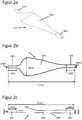
- Figures 2a, b, c show a schematic representation of an exemplary embodiment of the pulse damper (6).
- Figure 2a shows a perspective view
- FIG. 2b a plan view
- FIG. 2c a schematic cross section in the side view.
- the connection (602) designed as a hose-like inlet, which, for example, connects the gas metering unit (5) to the pulse damper (6), widens to form a chamber (604).
- the chamber (604) is set up and designed in such a way that the gas fed in by the gas metering unit (5) is also included a volume u 1 and can transition into a less pulsatile or steady flow.
- the pulse damper (6) is designed as a whole or at least the chamber is designed as an elastomer component so that the chamber can expand and also contract again.
- the chamber (604) gradually tapers into a connection (603) designed as a hose-like inlet, which connects the pulse damper with, for example, the main pneumatic line (4).
- the pulse damper is to be regarded as hollow and open, so that the gas can flow into the pulse damper (6), from connection (602) to connection (603) within the pulse damper (6) and then out of the pulse damper (6).
- the chamber top (605) and the chamber bottom (606) of the pulse damper (6) are spaced apart from one another, but it is also possible, for example, that opposing walls, for example the chamber top (605) and can touch the chamber bottom (606).
- the pulse damper (6) is constructed flat, for example, so the height in the non-expanded state is smaller than the maximum width.
- the height of the pulse damper is in the range of the diameter of the connections (602, 603).
- the pulse damper can also have a round cross section along the flow direction, that is, among other things, that the highest point is arranged in the area of the widest point and the maximum height corresponds to the maximum width or the diameter at this point corresponds to the maximum Width corresponds.
- the wall thickness of the pulse damper is between 0.5 mm and 5 mm, preferably between 0.7 mm and 2.5 mm.
- the total length Lmax of the pulse damper is between 30 mm and 500 mm, preferably between 60 mm and 250 mm.
- the maximum width Dmax of the pulse damper is between 20 mm and 100 mm, preferably between 30 mm and 70 mm.
- the ratio of the respective connection length of the connections (L602, L603) to the total length Lmax of the pulse damper (6) is, for example, from 1: 3 to 1:15, preferably from 1: 5 to 1:10.
- the ratio of the width of the connections (D602, D603) to the maximum width Dmax of the pulse damper is, for example, from 1: 5 to 1:25, preferably from 1: 7 to 1:17. If the connections are, for example, cylindrical, then the width of the connections would be synonymous with the diameter.
- the width D602 of the connector (602) is slightly smaller than the width D603 of the connector (603).
- the widths D602 and D603 can also be the same.
- the widths D602, D603 of the connections (602, 603) can be adapted, for example, to the connections of the preceding and following lines, for example the connection of the gas metering unit (5) or the main pneumatic line (4).
- the ratio of the maximum width Dmax to the total length Lmax of the pulse damper (6) is, for example, from 1: 1 to 1:10, preferably from 1: 2 to 1: 6.
- the widest point of the pulse damper (6) with a width Dmax is between 0.07 and 0.5 of the total length Lmax in the direction of flow, i.e. from connection (602) in the direction Connection (603).
- the widest point is preferably between 0.16 and 0.4 of the total length Lmax.
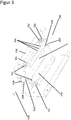
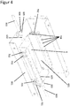
- Figures 3 to 5 show perspective, schematic representations of an exemplary embodiment of the pulse damper (6) in an exemplary embodiment of the pulse damper housing, which comprises an upper housing part (601) and a lower housing part (801).
- the upper housing part (601) is designed and set up, for example, in such a way that it has higher-lying edges and a lower-lying middle part.
- the lower middle part is located directly on the pulse damper (6) and completely covers, for example, the chamber (604) of the pulse damper (6).
- the lower middle part of the upper housing part is shown flat as an example. In further exemplary embodiments, this lower-lying middle part can also at least partially and / or roughly map the geometric shape of the chamber (604) of the pulse damper (6) in the non-expanded state.
- the higher-lying edges of the upper housing part (601) serve to enable the housing parts (601, 801) to be connected by spring elements (701, 702, 703).
- the housing parts (601, 801) there are corresponding holes (704) in the housing parts (601, 801), into which the spring elements (701, 702, 703) can, for example, be suspended and / or otherwise reversibly and / or permanently attached.
- the housing parts (601, 801) are connected via a type of hinge (705) in the front part - that is, on the side of the connection (603).
- the hinge (705) has the effect that the upper housing part (601) can lift when the pulse damper (6) expands at the rear end - that is, on the side of the connection (602). It therefore allows a certain rotation of the upper housing part (601) about the hinge axis.
- the hinge (705) - also in combination with a spring element, for example spring element (701) - can also be set up so that the housing part (601) can also be lifted in the area of the connection (603) or hinge (705) .
- the housing part (601) can therefore rise more at one end than at the opposite end. This ensures that a steady flow can arise even at higher pressures in the pulse damper (6).
- the spring constant of the spring element (701) in the area of the connection (603) is greater than that of the other spring elements.
- the attached spring elements (701, 702, 703) serve on the one hand as a resistance against lifting in the rear part of the upper housing part (601), on the other hand the spring elements (701, 702, 703) also serve to support the contraction and the associated venting of the gas from the pulse damper (6) into, for example, the main pneumatic line (4).
- the holes (704) made in the housing parts (601, 801) serve not only to hold the spring elements (701, 702, 703) but also to adjust the damper strength - i.e. the resistance to the expansion of the pulse damper and the support of the contraction - as required . If the spring elements (702) and (703) are hooked into holes further forward, for example, there is less resistance to expansion and thus less support for the contraction of the pulse damper (6).
- the use of more or fewer spring elements and also the combination of different spring strengths are possible in further embodiments.
- the upper housing part (601) can only be connected to the lower housing part (801) via one spring element (701) per side - i.e. a total of two spring elements (701) - which in turn is connected to the in Figures 3 to 6
- the position shown of the spring element (702) is placed.
- the number and / or the distance between the holes (704) for the spring elements can vary.
- the lower housing part (801) has holes (704) for fixing the spring elements (701, 702, 703).
- the lower housing part (801) comprises, for example, two raw mountings (805).
- these pipe holders are designed so that the connecting piece (804), which connects the connections (602, 603) of the pulse damper (6) with the connections (802, 803) of the other lines of the ventilator (1) - for example via a connector (802) with the gas metering unit (5).
- the connecting piece (804) is designed in such a way that it is matched to the dimensions of the respective connections (602, 603, 802, 803).
- the pipe holder (805) can also be adapted to this connecting piece, so that both have the same or at least similar geometric shape.
- the housing parts (601, 801) are made of aluminum, for example. But other stable materials such as plastics or steel are also possible.
Landscapes
- Health & Medical Sciences (AREA)
- Anesthesiology (AREA)
- Emergency Medicine (AREA)
- Life Sciences & Earth Sciences (AREA)
- Engineering & Computer Science (AREA)
- Biomedical Technology (AREA)
- Heart & Thoracic Surgery (AREA)
- Hematology (AREA)
- Pulmonology (AREA)
- Animal Behavior & Ethology (AREA)
- General Health & Medical Sciences (AREA)
- Public Health (AREA)
- Veterinary Medicine (AREA)
- Measuring Pulse, Heart Rate, Blood Pressure Or Blood Flow (AREA)
- Pipe Accessories (AREA)
- Percussion Or Vibration Massage (AREA)
Abstract
Description
- Die Erfindung betrifft ein Beatmungsgerät zur Beatmung eines Lebewesens.
- Beatmungsgeräte werden unter anderem zur Beatmung von Lebewesen mit einem Atemgas eingesetzt. Die Beatmung von Patienten in Krankenhäusern oder im häuslichen Umfeld mit einem Atemgas ist ein übliches Anwendungsfeld solcher Beatmungsgeräte. Im Bereich der Anästhesie können Beatmungsgeräte zum Teil auch als Anästhesiegeräte verwendet werden. Dazu wird dem Atemgas, welches dem Patienten zugeführt wird, ein zusätzliches Narkosegas zugemischt.
- Narkosegase, zum Beispiel Xenon, sind sehr teuer. Daher ist es vorteilhaft, wenn der Anteil des Narkosegases, welches nach dem Ausatmen noch in dem Atemgas vorhanden ist herausgefiltert oder wiederverwendet werden kann. Letzteres kann durch ein Beatmungsgerät realisiert werden, bei dem das Atemgas in einem Kreislauf geführt wird. D.h. es ist nötig aus dem ausgeatmeten Gasgemischt zum einen das ausgeatmete CO2 herauszufiltern und zum anderen verbrauchten Sauerstoff sowie Narkosegas wieder zuzusetzen.
- In der Regel findet bei solchen Geräten eine kontinuierliche Zufuhr von Narkosegas statt. Für eine weitere Einsparung von Narkosegas ist es möglich, das Narkosegas nur in kleinen Mengen in Form von kurzen Pulsen dem Atemgas beizumischen. Zusätzlich bietet das pulsförmige Einleiten des Narkosegases, z.B. über sehr schnelle Ventile, eine günstige und auch genaue Form der Dosierung.
- Solche Beatmungsgeräte sind bekannt.
- Ein Nachteil dieser pulsförmigen Zugabe von Narkosegas besteht darin, dass der dadurch entstehende Impuls auf den gesamten Gasfluss übertragen wird. Dadurch wird unter anderem die Messung des Gasflusses durch plötzlich auftretende Druckspitzen empfindlich gestört. Diese Impulse können mitunter eine solche Stärke haben, dass diese sich bis zum Patienteninterface fortsetzen und auch vom Patienten oder dem behandelnden Personal als störend wahrgenommen werden können.
- Die Aufgabe der vorliegenden Erfindung ist es, ein Beatmungsgerät bereit zu stellen, welches eine pulsförmige Zugabe von Narkosegas zum Atemgas zulässt, den dadurch gestörten Gasfluss aber beruhigen bzw. in einen stetigen Fluss überführen kann.
- Gemäß einem Aspekt der Erfindung wir die Aufgabe mit einem Beatmungsgerät mit einer Gasdosierungseinheit und einem Pulsdämpfer nach Anspruch 1 gelöst. Das Beatmungsgerät umfasst einen Druckerzeuger, eine Gasdosierungseinheit, eine pneumatische Hauptleitung, durch welche das Atemgas zum Patienteninterface geleitet wird, sowie einen Pulsdämpfer.
- Die Gasdosierungseinheit ist so eingerichtet Atemgas oder Zusätze zum Atemgas wie zum Beispiel Außenluft und/oder Sauerstoff und/oder Narkosegas in die pneumatische Hauptleitung zu leiten. Die Einleitung von Atemgas oder Zusätzen zum Atemgas ist auf bestimmte Mengen oder Volumina ausgelegt. Der Druckerzeuger ist dazu eingerichtet, das Atemgas in die pneumatische Hauptleitung zum Patienteninterface zu fördern.
- In einer Ausführungsform der Erfindung ist die Dosierungseinheit eingerichtet, dass das Atemgas oder die Zusätze zum Atemgas bereitzustellen indem Luft (z.B. Außenluft oder aus einer Druckluftflasche) und/oder Sauerstoff und/oder Narkosegas gemischt werden. Zudem verfügt die Gasdosierungseinheit über zumindest ein Ventil. Die genannten Impulswellen können beispielsweise durch die gepulste, schnelle Zuführung von bestimmten Mengen oder Volumina an Gas oder Gasgemischen durch die Dosierungseinheit entstehen.
- Der Pulsdämpfer des Beatmungsgeräts ist beispielsweise so ausgelegt und eingerichtet, dass Impulswellen der Atemgasquelle und/oder der Gasdosierungseinheit durch ebenjenen Pulsdämpfer gedämpft werden.
- In einer weiteren Ausführung des Beatmungsgeräts ist der Pulsdämpfer in Durchflussrichtung - ausgehend von der Dosierungseinheit und dem Druckgeber zum Patienteninterface - nach der Dosierungseinheit aber vor der pneumatischen Hauptleitung angeordnet. Die Gasdosierungseinheit ist dabei beispielsweise in Durchflussrichtung vor dem Druckerzeuger angeordnet, wobei der Druckerzeuger wiederum in Durchflussrichtung vor dem Patienteninterface angeordnet ist. Somit wäre zum Beispiel die Dämpfung der Impulswellen, welche durch die Dosierungseinheit erzeugt werden können, gegeben. Die Durchflussrichtung wird dabei beispielsweise durch eine nicht näher beschriebene Umwälzeinheit, beispielsweise eine Druckpumpe, bestimmt.
- Auch eine Anordnung von beispielsweise mehreren Pulsdämpfern zwischen Gasdosierungseinheit und pneumatischer Hauptleitung ist möglich.
- In einer weiteren Ausführung der Erfindung verfügt der Pulsdämpfer über einen Anschluss für die Gasdosierungseinheit sowie einen Anschluss für die pneumatische Hauptleitung. Diese Anschlüsse sind so zu verstehen, dass auch eine pneumatische Anordnung des Pulsdämpfers beispielsweise zwischen dem Druckerzeuger und der pneumatischen Hauptleitung realisiert werden kann.
- In einer weiteren Ausführungsform der Erfindung ist der Pulsdämpfer als elastomeres Bauteil ausgebildet. Der Pulsdämpfer umfasst dabei beispielsweise einen schlauchartigen Zulauf, welcher sich zu einer Kammer aufweitet. Die Kammer wiederum geht allmählich in einen schlauchartigen Auslauf über. Das Bauteil ist beispielsweise so ausgebildet, dass die die Aufweitung vom Zulauf zu der Kammer in einem sehr viel größeren Winkel erfolgt als der allmähliche Übergang der Kammer zu dem Auslauf.
- In einer weiteren Ausführungsform der Erfindung ist der Pulsdämpfer so eingerichtet, dass sich die das Volumen u1 des pulsartig durch die Dosierungseinheit zugeführten Gases in der Kammer ausbreiten kann und in einen weniger pulsartigen oder stetigen Fluss übergeht. Der zu erreichende, weniger pulsartige bzw. stetige Fluss in der pneumatischen Hauptleitung wird beispielsweise durch eine nicht näher beschriebene Umwälzeinheit vorgegeben.
- In einer weiteren Ausführungsform der Erfindung beträgt der zu erreichende, stetige Fluss in der pneumatischen Hauptleitung 20 bis 100 L/min, bevorzugt 30 bis 80 L/min.
- In einer weiteren Ausführungsform der Erfindung beträgt das Volumen u1 des pulsartig durch die Dosierungseinheit zugeführte Gas 1 bis 25 mL, bevorzugt 3 bis 15 mL.
- In einer Ausführungsform ist der Pulsdämpfer aus Silikon gefertigt. In einer weiteren Ausführungsform weißt der Pulsdämpfer eine gewisse Rauigkeit auf.
- In einer weiteren Ausführungsform der Erfindung umfasst die Kammer des Pulsdämpfers eine Oberfläche, welche beispielsweise zumindest teilweise mit einem Dämmmaterial ausgekleidet ist.
- In einer Ausführungsform der Erfindung ist der Pulsdämpfer in einem Pulsdämpfergehäuse platziert, welcher den Pulsdämpfer zum Beispiel mindestens teilweise bzw. abschnittsweise haltert. Das Pulsdämpfergehäuse weist beispielsweise mindestens ein Federelement auf. Das Federelement ist beispielsweise so ausgebildet und eingerichtet, dass eine auf den Fluss in der pneumatischen Hauptleitung abgestimmte Dämpferstärke erreicht werden kann.
- In manchen Ausführungsformen beträgt die Federkonstante eines der Federelemente zwischen 25 N/mm und 150 N/mm, bevorzugt zwischen 45 N/mm und 66 N/mm.
- In einer weiteren Ausführungsform sind der Pulsdämpfer, das Pulsdämpfergehäuse sowie die Federelemente so eingerichtet und ausgebildet, dass sie auf die eingeleitete Menge oder das eingeleitete Volumen u1 des Gases aus der Gasdosierungseinheit und/oder auf den Durchfluss in der pneumatischen Hauptleitung abgestimmt sind.
- In weiteren Ausführungsformen ist die Dämpferstärke des Pulsdämpfers durch Versetzen des zumindest einen Federelements einstellbar.
- In manchen Ausführungsformen ist daran gedacht, dass die Gehäuseteile über Scharnier miteinander verbunden sind, so dass sich ein Gehäuseteil beim Expandieren des Pulsdämpfers an einem Ende stärker anhebt als an dem gegenüberliegenden Ende.
- Auch ist in manchen Ausführungsformen daran gedacht, dass die Dämpferstärke des Pulsdämpfers über die Federstärke bzw. die Federkonstante des zumindest einen Federelements einstellbar ist.
- Das Funktionsprinzip des Pulsdämpfers basiert beispielsweise auf der Expansion mit nachfolgender Kontraktion des beispielhaft elastomeren Bauteils bei pulsartiger Einleitung des Gases durch die Gasdosierungseinheit. Wird eine bestimmte Menge Gas durch die Gasdosierungseinheit pulsartig in die pneumatische Hauptleitung eingeleitet, so erhöht sich der Druck bzw. der Fluss in der pneumatischen Hauptleitung sprunghaft. Wird der Pulsdämpfer, welcher auch einen gewissen pneumatischen Widerstand darstellt, zwischen Gasdosierungseinheit und der pneumatischen Hauptleitung eingesetzt, baut sich durch die pulsartige Einleitung des Gases ein Druck vor dem Pulsdämpfer auf. Diesem Druckanstieg kann der Pulsdämpfer nachgeben und dabei expandieren und so durch Volumenzunahme den Druckanstieg ausgleichen. Dabei dehnt sich die zugeleitete Gasmenge innerhalb des Pulsdämpfers aus. Zieht sich der Pulsdämpfer wieder zusammen, so wird das zugenommene Volumen bzw. die darin enthaltene Gasmenge allmählich dem Fluss in der pneumatischen Hauptleitung zugeführt. Dadurch wird die initiale Druck- bzw. Flusserhöhung durch die Gaseinleitung nicht auf die pneumatische Hauptleitung übertragen. Die beispielhaft an einem möglichen Pulsdämpfergehäuse angebrachten Federelemente können dazu dienen, die Dämpfstärke einzustellen und auch die Kontraktion des Pulsdämpfers zu unterstützen.
- Ein zweiter Aspekt der Erfindung umfasst einen Pulsdämpfer, welcher ausgebildet und eingerichtet ist um Impulswellen einer Gasquelle zu dämpfen. Der Pulsdämpfer ist beispielsweise als elastomeres Bauteil ausgebildet und verfügt über einen schlauchartigen Zulauf, welcher in eine Kammer über geht. Diese Kammer wiederum geht allmählich in einen schlauchartigen Auslauf über.
-
- Figur 1:
- Schematische Darstellung einer beispielhaften Ausführungsform eines Beatmungsgeräts
- Figur 2:
- Schematische Darstellung einer beispielhaften Ausführungsform eines Pulsdämpfers in perspektivischer Sicht (a), in Aufsicht (b) und Querschnitt in Seitansicht
- Figur 3:
- Schematische Darstellung einer beispielhaften Ausführungsform eines Pulsdämpfers mit Pulsdämpfergehäuse in perspektivischer Ansicht
- Figur 4:
- Schematische Darstellung einer beispielhaften Ausführungsform eines Pulsdämpfers mit Pulsdämpfergehäuse in perspektivischer Ansicht
- Figur 5:
- Schematische Darstellung einer beispielhaften Ausführungsform eines Pulsdämpfers mit Pulsdämpfergehäuse in perspektivischer Ansicht
-
Figur 1 zeigt eine schematische Darstellung einer beispielhaften Ausführungsform eines Beatmungsgeräts (1), welches beispielhaft über einen geschlossenen Gaskreislauf mit einem CO2-Absorber (8) verfügt. Das inFigur 1 dargestellte Beatmungsgerät (1) umfasst einen Druckerzeuger (2), eine Gasdosierungseinheit (5), eine pneumatische Hauptleitung (4) sowie einen Übergang zu dem Patienteninterface (9). - Über die Gasdosierungseinheit (5) wird bei Bedarf Narkosegas und/oder Sauerstoff und/oder Luft pulsartig in die pneumatische Hauptleitung eingeleitet. Der Druckerzeuger (2) fördert das Atemgas über die pneumatische Hauptleitung (4) zu dem Patienteninterface (9). Um die Impulswellen der pulsartigen Einleitung von Narkosegas und/oder Sauerstoff in die Hauptleitung (4) zu dämpfen ist der Pulsdämpfer (6) in
Figur 1 beispielhaft in Gasflussrichtung (d) nach der Gasdosierungseinheit (5) und vor der pneumatischen Hauptleitung (4) angeordnet. Der Pulsdämpfer (6) ist so eingerichtet, dass Impulswellen, entstehend durch die pulsartige Einleitung von Gas aus der Gasdosierungseinheit (5), gedämpft werden. Eine Umwälzeinheit (7) bestimmt den Durchfluss in der pneumatischen Hauptleitung und bewirkt eine schnelle Durchmischung des im Kreislauf geführten Atemgases mit den zugesetzten Gasen wie z.B. Sauerstoff oder Narkosegas. Der CO2-Absorber (8) entfernt das ausgeatmete CO2 des Patienten aus dem Atemgas in der pneumatischen Hauptleitung (4). - Neben der in
Figur 1 gezeigten und beschriebenen Anordnung des Pulsdämpfers (6) ergeben sich auch weitere mögliche Anordnungen. - Der Pulsdämpfer (6) kann beispielsweise auch in einer Weise entlang der pneumatischen Hauptleitung (4) angeordnet sein, dass der Pulsdämpfer (6) in einer Nebenleitung oder als eine Art Sackgasse von der Hauptleitung (4) abzweigt.
-
Figuren 2a, b, c zeigen ein schematische Darstellungen einer beispielhaften Ausführung des Pulsdämpfers (6).Figur 2a zeigt dabei eine perspektivische Ansicht, 2b eine Aufsicht und 2c einen schematischen Querschnitt in der Seitenansicht. Der als schlauchartige Zulauf ausgebildete Anschluss (602), welcher beispielhaft die Gasdosierungseinheit (5) mit dem Pulsdämpfer (6) verbindet, weitet sich zu einer Kammer (604) auf. Die Kammer (604) ist so eingerichtet und ausgebildet, dass sich das von der Gasdosiereinheit (5) eingespeiste Gas mit einem Volumen u1 ausbreiten kann und in einen weniger pulsartigen oder stetigen Fluss übergehen kann. Dazu ist beispielsweise der Pulsdämpfer (6) als Ganzes oder zumindest die Kammer als elastomeres Bauteil ausgebildet, sodass sich die Kammer erweitern und auch wieder zusammenziehen kann. Die Kammer (604) geht allmählich zulaufend in einen als schlauchartigen Zulauf ausgebildeten Anschluss (603) über, welcher den Pulsdämpfer mit zum Beispiel der pneumatischen Hauptleitung (4) verbindet. Insgesamt ist der Pulsdämpfer als hohl und offen anzusehen, sodass der Gasfluss in den Pulsdämpfer (6) hinein, von Anschluss (602) zu Anschluss (603) innerhalb des Pulsdämpfers (6) und dann aus den Pulsdämpfer (6) hinaus möglich ist. Im nicht-erweiterten Zustand des Pulsdämpfers (6) sind die Kammeroberseite (605) und die Kammerunterseite (606) des Pulsdämpfers (6) beabstandet voneinander, es ist aber auch möglich, dass sich zum Beispiel gegenüberliegende Wände, also beispielsweise die Kammeroberseite (605) und die Kammerunterseite (606) berühren können. - Wie in
Figur 2c zu erkennen, ist der Pulsdämpfer (6) beispielsweise Flach aufgebaut, die Höhe im nicht-erweiterten Zustand ist also kleiner als die maximale Breite. Beispielsweise liegt die Höhe des Pulsdämpfers im Bereich der Durchmesser der Anschlüsse (602, 603). In weiteren Ausführungsformen kann der Pulsdämpfer aber auch einen runden Querschnitt entlang der Durchflussrichtung aufweisen, das heißt unter anderem, dass die höchste Stelle im Bereich der breitesten Stelle angeordnet ist und auch die maximale Höhe der maximalen Breite entspricht bzw. der Durchmesser an dieser Stelle der maximalen Breite entspricht. - Die Wandstärke des Pulsdämpfers ist zwischen 0,5 mm und 5 mm, bevorzugt zwischen 0,7 mm und 2,5 mm.
- Die Gesamtlänge Lmax des Pulsdämpfers ist zwischen 30 mm und 500 mm, bevorzugt zwischen 60 mm und 250 mm.
- Die maximale Breite Dmax des Pulsdämpfers ist zwischen 20 mm und 100 mm, bevorzugt zwischen 30 mm und 70 mm.
- Das Verhältnis der jeweiligen Anschlusslänge der Anschlüsse (L602, L603) zu der Gesamtlänge Lmax des Pulsdämpfers (6) beträgt beispielsweise von 1:3 bis 1:15, bevorzugt von 1:5 bis 1:10.
- Das Verhältnis der Breite der Anschlüsse (D602, D603) zu der maximalen Breite Dmax des Pulsdämpfers beträgt beispielsweise von 1:5 bis 1:25, bevorzugt von 1:7 bis 1:17. Sind die Anschlüsse beispielweise zylinderförmig ausgebildet, so wäre die Breite der Anschlüsse gleichbedeutend mit dem Durchmesser. In der
Figur 2 gezeigten beispielhaften Ausführungsform ist die Breite D602 des Anschlusses (602) geringfügig kleiner als die Breite D603 des Anschlusses (603). Für weitere, nicht gezeigte, beispielhafte Ausführungsformen können die Breiten D602 und D603 auch gleich sein. In weiteren Ausführungsformen können die Breiten D602, D603 der Anschlüsse (602, 603) beispielsweise auf die Anschlüsse der vorhergehenden und nachfolgenden Leitungen, zum Beispiel den Anschluss der Gasdosierungseinheit (5) oder der pneumatischen Hauptleitung (4), angepasst sein. - Das Verhältnis der maximalen Breite Dmax zu der Gesamtlänge Lmax des Pulsdämpfers (6) beträgt beispielsweise von 1:1 bis 1:10, bevorzugt von 1:2 bis 1:6.
- Die breiteste Stelle des Pulsdämpfers (6) mit einer Breite Dmax ist befindet sich zwischen 0,07 und 0,5 der Gesamtlänge Lmax in Durchflussrichtung, also von Anschluss (602) in Richtung Anschluss (603). Bevorzugt befindet sich die breiteste Stelle zwischen 0,16 und 0,4 der Gesamtlänge Lmax.
- Es ist zu verstehen, dass die in
Figur 2 schematisch dargestellte Form des Pulsdämpfers (6) eine beispielhafte Form darstellt und der Pulsdämpfer (6) auch beliebige andere Formen annehmen kann. -
Figuren 3 bis 5 zeigen perspektivische, schematische Darstellungen einer beispielhaften Ausführung des Pulsdämpfers (6) in einer beispielhaften Ausführung des Pulsdämpfergehäuses, welches ein oberes Gehäuseteil (601) und ein unteres Gehäuseteil (801) umfasst. - Das obere Gehäuseteil (601) ist beispielsweise so ausgebildet und eingerichtet, dass es höher liegende Ränder und einen tieferliegenden Mittelteil aufweist. Der tieferliegende Mittelteil ist unmittelbar auf dem Pulsdämpfer (6) gelegen und deckt beispielsweise die Kammer (604) des Pulsdämpfers (6) vollständig ab. Der tieferliegende Mittelteil des oberen Gehäuseteils ist beispielhaft flach dargestellt. In weiteren beispielhaften Ausführungen kann dieser tieferliegende Mittelteil auch die geometrische Form der Kammer (604) des Pulsdämpfers (6) in nicht-expandiertem Zustand zumindest teilweise und/oder grob abbilden. Die höher liegenden Ränder des oberen Gehäuseteils (601) dienen dazu, dass die Gehäuseteile (601, 801) durch Federelemente (701, 702, 703) verbunden werden können. Dazu sind entsprechende Löcher (704) in den Gehäuseteilen (601, 801) vorhanden, in welche die Federelemente (701, 702, 703) beispielsweise eingehängt und/oder auf andere Weise reversibel und/oder permanent befestigt werden können. Zusätzlich sind die Gehäuseteile (601, 801) über eine Art Scharnier (705) im vorderen Teil - das heißt auf der Seite des Anschlusses (603) - verbunden. Das Scharnier (705) bewirkt in der beispielhaften Ausführungsform, dass sich das obere Gehäuseteil (601) beim Expandieren des Pulsdämpfers (6) am hinteren Ende - also auf der Seite des Anschlusses (602) - anheben kann. Es erlaubt also eine gewisse Rotation des oberen Gehäuseteils (601) um die Scharnierachse. Beispielsweise kann das Scharnier (705) - auch in Kombination mit einem Federelement, z.B. Federelement (701) - auch so eingerichtet sein, dass auch ein Anheben des Gehäuseteils (601) im Bereich des Anschlusses (603) bzw. Scharniers (705) möglich ist. Das Gehäuseteile (601) kann sich an einem Ende also stärker anheben als an dem gegenüberliegenden Ende. Dadurch kann gewährleistet sein, dass auch bei größeren Drücken im Pulsdämpfer (6) ein beruhigter Fluss entstehen kann. Dazu ist beispielweise die Federkonstante des Federelements (701) im Bereich des Anschlusses (603) größer als der übrigen Federelemente.
- Die angebrachten Federelemente (701, 702, 703) wiederum dienen zum einen als Widerstand gegen das Anheben im hinteren Teil des oberen Gehäuseteils (601), zum anderen dienen die Federelemente (701, 702, 703) auch der Unterstützung zum Zusammenziehen und damit verbundenen Auslassen des Gases aus dem Pulsdämpfer (6) in beispielsweise die pneumatische Hauptleitung (4).
- Die eingebrachten Löcher (704) in den Gehäuseteilen (601, 801) dienen neben der Halterung der Federelemente (701, 702, 703) auch dazu, die Dämpferstärke - also den Widerstand gegen die Expansion des Pulsdämpfers und die Unterstützung des Zusammenziehens - nach Bedarf einzustellen. Werden die Federelemente (702) und (703) beispielsweise in weiter vorne liegende Löcher eingehängt, so ergibt sich ein schwächerer Widerstand gegen die Expansion und somit auch eine schwächere Unterstützung des Zusammenziehens des Pulsdämpfers (6). Neben der hier beispielhaft gezeigten Ausführungsform mit insgesamt 6 Federelementen (je Seite drei Federelemente (701, 702, 703), insbesondere in
Figuren 4 und5 erkennbar) sind in weiteren Ausführungsformen auch der Einsatz von mehr oder weniger Federelementen und auch die Kombination verschiedener Federstärken möglich. So kann zum Beispiel in einer weiteren, nicht gezeigten Ausführungsform das obere Gehäuseteil (601) mit dem unteren Gehäuseteil (801) nur über ein Federelement (701) je Seite - also insgesamt zwei Federelemente (701) - verbunden, welches wiederum an der inFiguren 3 bis 6 gezeigte Position des Federelements (702) platziert ist. Weiter kann in weiteren beispielhaften Ausführungsformen die Anzahl und/oder der Abstand zwischen den Löchern (704) für die Federelemente variieren. Insbesondere inFigur 5 ist zu erkennen, dass das untere Gehäuseteil (801) Löcher (704) für die Fixierung der Federelemente (701, 702, 703) aufweist. - Ein Versetzen der Federelemente (701, 702, 703) führt zu einer Veränderung der Dämpferstärke, welche so einstellbar ist. Auch ist ein Einstellen der Dämpferstärke über die Federstärke bzw. die Federkonstante der verwendeten Federelemente (701, 702, 703) möglich.
- In den
Figuren 3 bis 5 werden jeweils drei Federelemente pro Seite, also insgesamt sechs Federelemente, gezeigt. In weiteren Ausführungen können auch mehr oder weniger Federelemente angeordnet sein. Auch die Position der Federelemente und/oder der Befestigungspunkte, wie z.B. die Löcher (704) können variieren. - Das untere Gehäuseteil (801) umfasst bespielhaft zwei Rohhalterungen (805). Wie in
Figuren 3 bis 5 schematisch dargestellt, sind diese Rohrhalterungen so ausgebildet, dass das Verbindungsstück (804), welches die Anschlüsse (602, 603) des Pulsdämpfers (6) mit den Anschlüssen (802, 803) der weiteren Leitungen des Beatmungsgeräts (1) verbindet - beispielsweise über Anschluss (802) mit der Gasdosierungseinheit (5). Das Verbindungsstück (804) ist dabei jeweils so ausgebildet, dass es auf die Abmessungen der jeweiligen Anschlüsse (602, 603, 802, 803) abgestimmt ist. Je nach geometrischer Form zum Beispiel des Verbindungsstücks (804) kann auch die Rohrhalterung (805) auf dieses Verbindungsstück angepasst sein, sodass beide über die gleiche oder zumindest ähnliche geometrische Form verfügen. - Die Gehäuseteile (601, 801) sind beispielsweise aus Aluminium hergestellt. Aber auch andere stabile Materialien wie Kunststoffe oder Stahl sind möglich.
-
- 1
- Beatmungsgerät
- 2
- Druckerzeuger
- 4
- pneumatische Hauptleitung
- 5
- Gasdosierungseinheit
- 6
- Pulsdämpfer
- 7
- Umwälzeinheit
- 8
- CO2-Absorber
- 9
- Patienteninterface
- 601
- (oberes) Gehäuseteil
- 602
- Anschluss
- 603
- Anschluss
- 604
- Kammer
- 605
- Kammeroberseite
- 606
- Kammerunterseite
- 701
- Federelement
- 702
- Federelement
- 703
- Federelement
- 704
- Loch
- 705
- Scharnier
- 801
- (unteres) Gehäuseteil
- 802
- Anschluss
- 803
- Anschluss
- 804
- Verbindungsstück
- 805
- Rohrhalterung
- d
- Durchflussrichtung
Claims (15)
- Beatmungsgerät (1) mit einem Druckerzeuger (2), einer Gasdosierungseinheit (5) und einer pneumatischen Hauptleitung (4), die Atemgas zu einem Patienteninterface leitet, dadurch gekennzeichnet, dass- die Gasdosierungseinheit (5) eingerichtet ist als Atemgas Außenluft und/oder Sauerstoff und/oder Narkosegas in die pneumatische Hauptleitung (4) zu leiten, und- der Druckerzeuger (2) eingerichtet ist, Atemgas in die pneumatische Hauptleitung zu dem Patienteninterface (9) zu fördern,wobei die Gasdosierungseinheit (5) eingerichtet ist, bestimmte Mengen oder Volumina an Atemgas in die pneumatische Hauptleitung (4) zu liefern, wobei das Beatmungsgerät einen Pulsdämpfer (6) aufweist.
- Beatmungsgerät (1) nach Anspruch 1 dadurch gekennzeichnet, dass die Gasdosierungseinheit (5) eingerichtet ist, Atemgas bereitzustellen indem Luft und/oder Sauerstoff und/oder Narkosegas gemischt werden, wobei die Gasdosierungseinheit (5) zumindest ein Ventil aufweist.
- Beatmungsgerät (1) nach Anspruch 1 dadurch gekennzeichnet, dass der Pulsdämpfer (6) eingerichtet ist, Impulswellen der Atemgasquelle (2) und/oder der Gasdosierungseinheit (5) zu dämpfen.
- Beatmungsgerät (1) nach zumindest einem der vorhergehenden Ansprüche dadurch gekennzeichnet, dass die pneumatische Hauptleitung (4) eine Durchflussrichtung (d) von der Gasdosierungseinheit (5) und dem Druckerzeuger (2) zum Patienteninterface aufweist, wobei die Gasdosierungseinheit (5) in Durchflussrichtung (d) vor dem Druckerzeuger (2) angeordnet ist und der Druckerzeuger (2) in Durchflussrichtung (d) vor dem Patienteninterface (9) oder der Druckerzeuger (2) in Durchflussrichtung (d) vor der Gasdosierungseinheit (5) angeordnet ist und die Gasdosierungseinheit (5) in Durchflussrichtung (d) vor dem Patienteninterface (9).
- Beatmungsgerät (1) nach zumindest einem der vorhergehenden Ansprüche dadurch gekennzeichnet, dass der Pulsdämpfer (6) pneumatisch zwischen der Gasdosierungseinheit (5) und der pneumatischen Hauptleitung (4) angeordnet ist und einen Anschluss (602) für die Gasdosierungseinheit 5 und einen Anschluss (603) für pneumatische Hauptleitung (4) aufweist.
- Beatmungsgerät (1) nach zumindest einem der vorhergehenden Ansprüche dadurch gekennzeichnet, dass der Pulsdämpfer (6) pneumatisch hinter der Gasdosierungseinheit (5) und/oder dem Druckerzeuger (2) in der pneumatischen Hauptleitung (4) angeordnet ist.
- Beatmungsgerät (1) nach zumindest einem der vorhergehenden Ansprüche dadurch gekennzeichnet, dass der Pulsdämpfer (6) als elastomeres Bauteil ausgebildet ist, mit einem schlauchartigen Zulauf vom Anschluss (602) der sich zu einer Kammer (604) aufweitet, wobei die Kammer (604) allmählich in einen schlauchartigen Auslauf zum Anschluss (603) übergeht.
- Beatmungsgerät (1) nach zumindest einem der vorhergehenden Ansprüche dadurch gekennzeichnet, dass der Pulsdämpfer (6) so eingerichtet und ausgebildet ist, dass sich das Volumen (ui) des pulsartig eingespeisten Atemgases in der Kammer (604) ausbreiten kann und in einen weniger pulsartigen (oder stetigen) Fluss überführt wird.
- Beatmungsgerät (2) nach zumindest einem der vorhergehenden Ansprüche dadurch gekennzeichnet, dass der Pulsdämpfer (6) so eingerichtet und ausgebildet ist, dass sich das Volumen (ui) des pulsartig eingespeisten Atemgases in der Kammer (604) ausbreiten kann und in einen weniger pulsartigen (oder stetigen) Fluss überführt wird, wobei der entstehende, weniger pulsartige (oder stetige) Fluss angepasst an den Durchfluss in der pneumatischen Hauptleitung (4) ist und von 20 bis 100 L/min, bevorzugt von 30 bis 80 L/min beträgt.
- Beatmungsgerät (1) nach zumindest einem der vorhergehenden Ansprüche dadurch gekennzeichnet, dass in der Kammer (604) eine Oberfläche gegeben ist, welche zumindest teilweise mit Dämmmaterial ausgekleidet ist.
- Beatmungsgerät (1) nach zumindest einem der vorhergehenden Ansprüche dadurch gekennzeichnet, dass der Pulsdämpfer (6) in einem Pulsdämpfergehäuse, umfassend einen oberen Gehäuseteil (601) und einen unteren Gehäuseteil (801) platziert ist, welches den Pulsdämpfer (6) zumindest teilweise oder abschnittsweise haltert, wobei das Pulsdämpfergehäuse (601) zumindest ein Federelement (701, 702, 703) aufweist.
- Beatmungsgerät (1) nach zumindest einem der vorhergehenden Ansprüche, dadurch gekennzeichnet, dass die Dämpferstärke des Pulsdämpfers (6) durch Versetzen des zumindest einen Federelements (701, 702, 703) einstellbar ist.
- Beatmungsgerät (1) nach zumindest einem der vorhergehenden Ansprüche, dadurch gekennzeichnet, dass das die Gehäuseteile (601, 801) über ein Scharnier (705) so miteinander verbunden sind, dass sich das Gehäuseteil (601) bei Expandieren des Pulsdämpfers (6) an einem Ende stärker anhebt als an dem gegenüberliegenden Ende.
- Beatmungsgerät (1) nach zumindest einem der vorhergehenden Ansprüche, dadurch gekennzeichnet, dass die Dämpferstärke des Pulsdämpfers (6) über die Federstärke des zumindest einen Federelements (701, 702, 703) einstellbar ist.
- Pulsdämpfer (6) eingerichtet und ausgebildet um Impulswellen einer Gasquelle zu dämpfen, dadurch gekennzeichnet, dass der Pulsdämpfer (6)- als elastomeres Bauteil ausgebildet ist und- einem schlauchartigen Zulauf (602) der sich zu einer Kammer (604) aufweitet, wobei die Kammer (604) allmählich in einen schlauchartigen Auslauf (603) überführt wird, umfasst.
Applications Claiming Priority (1)
| Application Number | Priority Date | Filing Date | Title |
|---|---|---|---|
| DE102020002439 | 2020-04-23 |
Publications (3)
| Publication Number | Publication Date |
|---|---|
| EP3909632A2 true EP3909632A2 (de) | 2021-11-17 |
| EP3909632A3 EP3909632A3 (de) | 2022-01-19 |
| EP3909632B1 EP3909632B1 (de) | 2023-03-22 |
Family
ID=75588028
Family Applications (1)
| Application Number | Title | Priority Date | Filing Date |
|---|---|---|---|
| EP21020212.3A Active EP3909632B1 (de) | 2020-04-23 | 2021-04-19 | Beatmungsgerät zur beatmung eines lebewesens |
Country Status (2)
| Country | Link |
|---|---|
| EP (1) | EP3909632B1 (de) |
| DE (1) | DE102021001997A1 (de) |
Families Citing this family (1)
| Publication number | Priority date | Publication date | Assignee | Title |
|---|---|---|---|---|
| DE102023001116A1 (de) * | 2023-03-22 | 2024-09-26 | GRÜNDLER GmbH | System zur Kopplung mit einem Beatmungsgerät |
Family Cites Families (6)
| Publication number | Priority date | Publication date | Assignee | Title |
|---|---|---|---|---|
| US781939A (en) * | 1903-02-26 | 1905-02-07 | Weston M Fulton | Collapsible vessel. |
| FR1554785A (de) * | 1967-11-21 | 1969-01-24 | ||
| FR2125847A5 (de) * | 1971-02-16 | 1972-09-29 | Kloeckner Humboldt Deutz Ag | |
| EP0282675A3 (de) * | 1986-11-04 | 1990-01-03 | Bird Products Corporation | Strömungskontrollventil für medizinische Beatmungsgeräte |
| US6041777A (en) * | 1995-12-01 | 2000-03-28 | Alliance Pharmaceutical Corp. | Methods and apparatus for closed-circuit ventilation therapy |
| US8118024B2 (en) * | 2003-08-04 | 2012-02-21 | Carefusion 203, Inc. | Mechanical ventilation system utilizing bias valve |
-
2021
- 2021-04-16 DE DE102021001997.0A patent/DE102021001997A1/de active Pending
- 2021-04-19 EP EP21020212.3A patent/EP3909632B1/de active Active
Also Published As
| Publication number | Publication date |
|---|---|
| EP3909632B1 (de) | 2023-03-22 |
| EP3909632A3 (de) | 2022-01-19 |
| DE102021001997A1 (de) | 2021-10-28 |
Similar Documents
| Publication | Publication Date | Title |
|---|---|---|
| DE69417439T2 (de) | Zufuhrvorrichtung von sauerstoff und/oder anderen gasen zu einem patienten | |
| DE69123750T2 (de) | Unter umgebungsdruck arbeitender luft-sauerstoffmischer | |
| DE69530504T2 (de) | In-line venturi | |
| DE2227193A1 (de) | Nasenkanüle | |
| DE102012006396A1 (de) | Tracheostomietubus | |
| DE102021113642A1 (de) | Verbindungs-Anordnung mit einem Volumenfluss-Sensor und einer Homogenisierungseinheit zur künstlichen Beatmung eines Patienten sowie ein Herstellungsverfahren | |
| EP3554605A1 (de) | Nasenkanüle für high-flow-beatmung | |
| EP3096827B1 (de) | Vorrichtung zur beatmung und verfahren zur anreicherung von atemgas mit additiven | |
| DE10046872B4 (de) | Atmungsunterstützungsvorrichtung | |
| DE1936776A1 (de) | Zur Atmung dienende Leitungsanordnung | |
| EP3624883A1 (de) | Exspirationsventil für eine beatmungsvorrichtung mit geräuschminderndem strömungswiderstand | |
| DE2340611A1 (de) | Fluessigkeitssteuersystem zur steuerung der flussmenge bei intravenoesen infusionen | |
| EP3909632B1 (de) | Beatmungsgerät zur beatmung eines lebewesens | |
| DE19757703C5 (de) | Beatmungsvorrichtung | |
| EP1987864B1 (de) | Therapiegerät | |
| DE60317309T2 (de) | Beatmungsvorrichtung | |
| DE102022132952A1 (de) | Versorgungs-Anordnung und Versorgungs-Verfahren zur Versorgung einer patientenseitigen Koppeleinheit mit einem Gasgemisch | |
| EP2540334B1 (de) | Beatmungssystem | |
| DE202020106578U1 (de) | Vorrichtung zum Koppeln einer Beatmungsmaske oder eines nicht-invasiven Systems mit einem Luft-Sauerstoff-Mischer zur High-Flow-Oxygen-Therapie | |
| DE1933266A1 (de) | Verfahren zum Mischen von Druckgasen,insbesondere fuer Atmungs- und medizinische Geraete | |
| EP3100770A1 (de) | Zumischer für eine feuerlöschvorrichtung | |
| DE4142295C2 (de) | Ventil zur Erzeugung eines Steuerdrucks | |
| DE2406679C3 (de) | Hilfsvorrichtung für druck-, druckdurchfluB- oder volumengesteuerte Beatmungsgeräte | |
| EP3856314B1 (de) | Leckagenventil sowie beatmungsschlauchsystem | |
| DE8906449U1 (de) | Beatmungsbeutel mit einem die PEEP-Beatmung ermöglichenden Ventil |
Legal Events
| Date | Code | Title | Description |
|---|---|---|---|
| PUAI | Public reference made under article 153(3) epc to a published international application that has entered the european phase |
Free format text: ORIGINAL CODE: 0009012 |
|
| STAA | Information on the status of an ep patent application or granted ep patent |
Free format text: STATUS: THE APPLICATION HAS BEEN PUBLISHED |
|
| AK | Designated contracting states |
Kind code of ref document: A2 Designated state(s): AL AT BE BG CH CY CZ DE DK EE ES FI FR GB GR HR HU IE IS IT LI LT LU LV MC MK MT NL NO PL PT RO RS SE SI SK SM TR |
|
| PUAL | Search report despatched |
Free format text: ORIGINAL CODE: 0009013 |
|
| AK | Designated contracting states |
Kind code of ref document: A3 Designated state(s): AL AT BE BG CH CY CZ DE DK EE ES FI FR GB GR HR HU IE IS IT LI LT LU LV MC MK MT NL NO PL PT RO RS SE SI SK SM TR |
|
| RIC1 | Information provided on ipc code assigned before grant |
Ipc: A61M 16/20 20060101ALI20211215BHEP Ipc: A61M 16/12 20060101ALI20211215BHEP Ipc: A61M 16/08 20060101ALI20211215BHEP Ipc: A61M 16/10 20060101ALI20211215BHEP Ipc: A61M 16/00 20060101ALI20211215BHEP Ipc: A61M 16/01 20060101AFI20211215BHEP |
|
| STAA | Information on the status of an ep patent application or granted ep patent |
Free format text: STATUS: REQUEST FOR EXAMINATION WAS MADE |
|
| 17P | Request for examination filed |
Effective date: 20220621 |
|
| RBV | Designated contracting states (corrected) |
Designated state(s): AL AT BE BG CH CY CZ DE DK EE ES FI FR GB GR HR HU IE IS IT LI LT LU LV MC MK MT NL NO PL PT RO RS SE SI SK SM TR |
|
| GRAP | Despatch of communication of intention to grant a patent |
Free format text: ORIGINAL CODE: EPIDOSNIGR1 |
|
| STAA | Information on the status of an ep patent application or granted ep patent |
Free format text: STATUS: GRANT OF PATENT IS INTENDED |
|
| INTG | Intention to grant announced |
Effective date: 20221020 |
|
| GRAS | Grant fee paid |
Free format text: ORIGINAL CODE: EPIDOSNIGR3 |
|
| GRAJ | Information related to disapproval of communication of intention to grant by the applicant or resumption of examination proceedings by the epo deleted |
Free format text: ORIGINAL CODE: EPIDOSDIGR1 |
|
| GRAL | Information related to payment of fee for publishing/printing deleted |
Free format text: ORIGINAL CODE: EPIDOSDIGR3 |
|
| STAA | Information on the status of an ep patent application or granted ep patent |
Free format text: STATUS: REQUEST FOR EXAMINATION WAS MADE |
|
| GRAP | Despatch of communication of intention to grant a patent |
Free format text: ORIGINAL CODE: EPIDOSNIGR1 |
|
| STAA | Information on the status of an ep patent application or granted ep patent |
Free format text: STATUS: GRANT OF PATENT IS INTENDED |
|
| INTC | Intention to grant announced (deleted) | ||
| GRAA | (expected) grant |
Free format text: ORIGINAL CODE: 0009210 |
|
| STAA | Information on the status of an ep patent application or granted ep patent |
Free format text: STATUS: THE PATENT HAS BEEN GRANTED |
|
| INTG | Intention to grant announced |
Effective date: 20230123 |
|
| AK | Designated contracting states |
Kind code of ref document: B1 Designated state(s): AL AT BE BG CH CY CZ DE DK EE ES FI FR GB GR HR HU IE IS IT LI LT LU LV MC MK MT NL NO PL PT RO RS SE SI SK SM TR |
|
| REG | Reference to a national code |
Ref country code: GB Ref legal event code: FG4D Free format text: NOT ENGLISH |
|
| REG | Reference to a national code |
Ref country code: CH Ref legal event code: EP |
|
| REG | Reference to a national code |
Ref country code: IE Ref legal event code: FG4D Free format text: LANGUAGE OF EP DOCUMENT: GERMAN |
|
| REG | Reference to a national code |
Ref country code: DE Ref legal event code: R096 Ref document number: 502021000502 Country of ref document: DE |
|
| REG | Reference to a national code |
Ref country code: AT Ref legal event code: REF Ref document number: 1554913 Country of ref document: AT Kind code of ref document: T Effective date: 20230415 |
|
| P01 | Opt-out of the competence of the unified patent court (upc) registered |
Effective date: 20230522 |
|
| REG | Reference to a national code |
Ref country code: LT Ref legal event code: MG9D |
|
| REG | Reference to a national code |
Ref country code: NL Ref legal event code: MP Effective date: 20230322 |
|
| PG25 | Lapsed in a contracting state [announced via postgrant information from national office to epo] |
Ref country code: RS Free format text: LAPSE BECAUSE OF FAILURE TO SUBMIT A TRANSLATION OF THE DESCRIPTION OR TO PAY THE FEE WITHIN THE PRESCRIBED TIME-LIMIT Effective date: 20230322 Ref country code: NO Free format text: LAPSE BECAUSE OF FAILURE TO SUBMIT A TRANSLATION OF THE DESCRIPTION OR TO PAY THE FEE WITHIN THE PRESCRIBED TIME-LIMIT Effective date: 20230622 Ref country code: LV Free format text: LAPSE BECAUSE OF FAILURE TO SUBMIT A TRANSLATION OF THE DESCRIPTION OR TO PAY THE FEE WITHIN THE PRESCRIBED TIME-LIMIT Effective date: 20230322 Ref country code: LT Free format text: LAPSE BECAUSE OF FAILURE TO SUBMIT A TRANSLATION OF THE DESCRIPTION OR TO PAY THE FEE WITHIN THE PRESCRIBED TIME-LIMIT Effective date: 20230322 Ref country code: HR Free format text: LAPSE BECAUSE OF FAILURE TO SUBMIT A TRANSLATION OF THE DESCRIPTION OR TO PAY THE FEE WITHIN THE PRESCRIBED TIME-LIMIT Effective date: 20230322 |
|
| PG25 | Lapsed in a contracting state [announced via postgrant information from national office to epo] |
Ref country code: SE Free format text: LAPSE BECAUSE OF FAILURE TO SUBMIT A TRANSLATION OF THE DESCRIPTION OR TO PAY THE FEE WITHIN THE PRESCRIBED TIME-LIMIT Effective date: 20230322 Ref country code: NL Free format text: LAPSE BECAUSE OF FAILURE TO SUBMIT A TRANSLATION OF THE DESCRIPTION OR TO PAY THE FEE WITHIN THE PRESCRIBED TIME-LIMIT Effective date: 20230322 Ref country code: GR Free format text: LAPSE BECAUSE OF FAILURE TO SUBMIT A TRANSLATION OF THE DESCRIPTION OR TO PAY THE FEE WITHIN THE PRESCRIBED TIME-LIMIT Effective date: 20230623 Ref country code: FI Free format text: LAPSE BECAUSE OF FAILURE TO SUBMIT A TRANSLATION OF THE DESCRIPTION OR TO PAY THE FEE WITHIN THE PRESCRIBED TIME-LIMIT Effective date: 20230322 |
|
| PG25 | Lapsed in a contracting state [announced via postgrant information from national office to epo] |
Ref country code: SM Free format text: LAPSE BECAUSE OF FAILURE TO SUBMIT A TRANSLATION OF THE DESCRIPTION OR TO PAY THE FEE WITHIN THE PRESCRIBED TIME-LIMIT Effective date: 20230322 Ref country code: RO Free format text: LAPSE BECAUSE OF FAILURE TO SUBMIT A TRANSLATION OF THE DESCRIPTION OR TO PAY THE FEE WITHIN THE PRESCRIBED TIME-LIMIT Effective date: 20230322 Ref country code: PT Free format text: LAPSE BECAUSE OF FAILURE TO SUBMIT A TRANSLATION OF THE DESCRIPTION OR TO PAY THE FEE WITHIN THE PRESCRIBED TIME-LIMIT Effective date: 20230724 Ref country code: ES Free format text: LAPSE BECAUSE OF FAILURE TO SUBMIT A TRANSLATION OF THE DESCRIPTION OR TO PAY THE FEE WITHIN THE PRESCRIBED TIME-LIMIT Effective date: 20230322 Ref country code: EE Free format text: LAPSE BECAUSE OF FAILURE TO SUBMIT A TRANSLATION OF THE DESCRIPTION OR TO PAY THE FEE WITHIN THE PRESCRIBED TIME-LIMIT Effective date: 20230322 |
|
| PG25 | Lapsed in a contracting state [announced via postgrant information from national office to epo] |
Ref country code: SK Free format text: LAPSE BECAUSE OF FAILURE TO SUBMIT A TRANSLATION OF THE DESCRIPTION OR TO PAY THE FEE WITHIN THE PRESCRIBED TIME-LIMIT Effective date: 20230322 Ref country code: PL Free format text: LAPSE BECAUSE OF FAILURE TO SUBMIT A TRANSLATION OF THE DESCRIPTION OR TO PAY THE FEE WITHIN THE PRESCRIBED TIME-LIMIT Effective date: 20230322 Ref country code: IS Free format text: LAPSE BECAUSE OF FAILURE TO SUBMIT A TRANSLATION OF THE DESCRIPTION OR TO PAY THE FEE WITHIN THE PRESCRIBED TIME-LIMIT Effective date: 20230722 |
|
| PG25 | Lapsed in a contracting state [announced via postgrant information from national office to epo] |
Ref country code: LU Free format text: LAPSE BECAUSE OF NON-PAYMENT OF DUE FEES Effective date: 20230419 |
|
| REG | Reference to a national code |
Ref country code: DE Ref legal event code: R097 Ref document number: 502021000502 Country of ref document: DE |
|
| REG | Reference to a national code |
Ref country code: BE Ref legal event code: MM Effective date: 20230430 |
|
| PG25 | Lapsed in a contracting state [announced via postgrant information from national office to epo] |
Ref country code: MC Free format text: LAPSE BECAUSE OF FAILURE TO SUBMIT A TRANSLATION OF THE DESCRIPTION OR TO PAY THE FEE WITHIN THE PRESCRIBED TIME-LIMIT Effective date: 20230322 |
|
| PLBE | No opposition filed within time limit |
Free format text: ORIGINAL CODE: 0009261 |
|
| STAA | Information on the status of an ep patent application or granted ep patent |
Free format text: STATUS: NO OPPOSITION FILED WITHIN TIME LIMIT |
|
| PG25 | Lapsed in a contracting state [announced via postgrant information from national office to epo] |
Ref country code: SI Free format text: LAPSE BECAUSE OF FAILURE TO SUBMIT A TRANSLATION OF THE DESCRIPTION OR TO PAY THE FEE WITHIN THE PRESCRIBED TIME-LIMIT Effective date: 20230322 Ref country code: MC Free format text: LAPSE BECAUSE OF FAILURE TO SUBMIT A TRANSLATION OF THE DESCRIPTION OR TO PAY THE FEE WITHIN THE PRESCRIBED TIME-LIMIT Effective date: 20230322 Ref country code: DK Free format text: LAPSE BECAUSE OF FAILURE TO SUBMIT A TRANSLATION OF THE DESCRIPTION OR TO PAY THE FEE WITHIN THE PRESCRIBED TIME-LIMIT Effective date: 20230322 Ref country code: CZ Free format text: LAPSE BECAUSE OF FAILURE TO SUBMIT A TRANSLATION OF THE DESCRIPTION OR TO PAY THE FEE WITHIN THE PRESCRIBED TIME-LIMIT Effective date: 20230322 |
|
| REG | Reference to a national code |
Ref country code: IE Ref legal event code: MM4A |
|
| 26N | No opposition filed |
Effective date: 20240102 |
|
| PG25 | Lapsed in a contracting state [announced via postgrant information from national office to epo] |
Ref country code: BE Free format text: LAPSE BECAUSE OF NON-PAYMENT OF DUE FEES Effective date: 20230430 |
|
| PG25 | Lapsed in a contracting state [announced via postgrant information from national office to epo] |
Ref country code: IE Free format text: LAPSE BECAUSE OF NON-PAYMENT OF DUE FEES Effective date: 20230419 |
|
| PG25 | Lapsed in a contracting state [announced via postgrant information from national office to epo] |
Ref country code: IE Free format text: LAPSE BECAUSE OF NON-PAYMENT OF DUE FEES Effective date: 20230419 |
|
| PG25 | Lapsed in a contracting state [announced via postgrant information from national office to epo] |
Ref country code: IT Free format text: LAPSE BECAUSE OF FAILURE TO SUBMIT A TRANSLATION OF THE DESCRIPTION OR TO PAY THE FEE WITHIN THE PRESCRIBED TIME-LIMIT Effective date: 20230322 |
|
| PG25 | Lapsed in a contracting state [announced via postgrant information from national office to epo] |
Ref country code: BG Free format text: LAPSE BECAUSE OF FAILURE TO SUBMIT A TRANSLATION OF THE DESCRIPTION OR TO PAY THE FEE WITHIN THE PRESCRIBED TIME-LIMIT Effective date: 20230322 |
|
| PG25 | Lapsed in a contracting state [announced via postgrant information from national office to epo] |
Ref country code: BG Free format text: LAPSE BECAUSE OF FAILURE TO SUBMIT A TRANSLATION OF THE DESCRIPTION OR TO PAY THE FEE WITHIN THE PRESCRIBED TIME-LIMIT Effective date: 20230322 |
|
| REG | Reference to a national code |
Ref country code: CH Ref legal event code: PL |
|
| PG25 | Lapsed in a contracting state [announced via postgrant information from national office to epo] |
Ref country code: CH Free format text: LAPSE BECAUSE OF NON-PAYMENT OF DUE FEES Effective date: 20240430 |
|
| PGFP | Annual fee paid to national office [announced via postgrant information from national office to epo] |
Ref country code: AT Payment date: 20250721 Year of fee payment: 5 |
|
| PG25 | Lapsed in a contracting state [announced via postgrant information from national office to epo] |
Ref country code: CY Free format text: LAPSE BECAUSE OF FAILURE TO SUBMIT A TRANSLATION OF THE DESCRIPTION OR TO PAY THE FEE WITHIN THE PRESCRIBED TIME-LIMIT; INVALID AB INITIO Effective date: 20210419 |
|
| PG25 | Lapsed in a contracting state [announced via postgrant information from national office to epo] |
Ref country code: HU Free format text: LAPSE BECAUSE OF FAILURE TO SUBMIT A TRANSLATION OF THE DESCRIPTION OR TO PAY THE FEE WITHIN THE PRESCRIBED TIME-LIMIT; INVALID AB INITIO Effective date: 20210419 |
|
| PG25 | Lapsed in a contracting state [announced via postgrant information from national office to epo] |
Ref country code: TR Free format text: LAPSE BECAUSE OF FAILURE TO SUBMIT A TRANSLATION OF THE DESCRIPTION OR TO PAY THE FEE WITHIN THE PRESCRIBED TIME-LIMIT Effective date: 20230322 |
|
| PGFP | Annual fee paid to national office [announced via postgrant information from national office to epo] |
Ref country code: GB Payment date: 20260324 Year of fee payment: 6 |
|
| PG25 | Lapsed in a contracting state [announced via postgrant information from national office to epo] |
Ref country code: CH Free format text: THE PATENT HAS BEEN ANNULLED BY A DECISION OF A NATIONAL AUTHORITY Effective date: 20240430 |
|
| PGFP | Annual fee paid to national office [announced via postgrant information from national office to epo] |
Ref country code: DE Payment date: 20260420 Year of fee payment: 6 |
|
| PG25 | Lapsed in a contracting state [announced via postgrant information from national office to epo] |
Ref country code: MT Free format text: LAPSE BECAUSE OF NON-PAYMENT OF DUE FEES Effective date: 20230419 |
|
| PGFP | Annual fee paid to national office [announced via postgrant information from national office to epo] |
Ref country code: FR Payment date: 20260423 Year of fee payment: 6 |