EP3909463B1 - Kosmetikbehälter mit einem einziehbaren knopf - Google Patents
Kosmetikbehälter mit einem einziehbaren knopf Download PDFInfo
- Publication number
- EP3909463B1 EP3909463B1 EP19909554.8A EP19909554A EP3909463B1 EP 3909463 B1 EP3909463 B1 EP 3909463B1 EP 19909554 A EP19909554 A EP 19909554A EP 3909463 B1 EP3909463 B1 EP 3909463B1
- Authority
- EP
- European Patent Office
- Prior art keywords
- guide
- button
- pressing
- pumping
- cosmetic container
- Prior art date
- Legal status (The legal status is an assumption and is not a legal conclusion. Google has not performed a legal analysis and makes no representation as to the accuracy of the status listed.)
- Active
Links
Images




Classifications
-
- B—PERFORMING OPERATIONS; TRANSPORTING
- B65—CONVEYING; PACKING; STORING; HANDLING THIN OR FILAMENTARY MATERIAL
- B65D—CONTAINERS FOR STORAGE OR TRANSPORT OF ARTICLES OR MATERIALS, e.g. BAGS, BARRELS, BOTTLES, BOXES, CANS, CARTONS, CRATES, DRUMS, JARS, TANKS, HOPPERS, FORWARDING CONTAINERS; ACCESSORIES, CLOSURES, OR FITTINGS THEREFOR; PACKAGING ELEMENTS; PACKAGES
- B65D33/00—Details of, or accessories for, sacks or bags
- B65D33/16—End- or aperture-closing arrangements or devices
- B65D33/1658—Elements for flattening or folding the mouth portion
- B65D33/1666—Slitted tubes with or without a core; U-shaped clips made of one piece
-
- B—PERFORMING OPERATIONS; TRANSPORTING
- B05—SPRAYING OR ATOMISING IN GENERAL; APPLYING FLUENT MATERIALS TO SURFACES, IN GENERAL
- B05B—SPRAYING APPARATUS; ATOMISING APPARATUS; NOZZLES
- B05B11/00—Single-unit hand-held apparatus in which flow of contents is produced by the muscular force of the operator at the moment of use
- B05B11/01—Single-unit hand-held apparatus in which flow of contents is produced by the muscular force of the operator at the moment of use characterised by the means producing the flow
- B05B11/10—Pump arrangements for transferring the contents from the container to a pump chamber by a sucking effect and forcing the contents out through the dispensing nozzle
- B05B11/1001—Piston pumps
- B05B11/1005—Piston pumps with means for adjusting or modifying pump stroke
- B05B11/1007—Piston pumps with means for adjusting or modifying pump stroke by adjusting or modifying the pump end-of-sucking-stroke position
-
- A—HUMAN NECESSITIES
- A45—HAND OR TRAVELLING ARTICLES
- A45D—HAIRDRESSING OR SHAVING EQUIPMENT; EQUIPMENT FOR COSMETICS OR COSMETIC TREATMENTS, e.g. FOR MANICURING OR PEDICURING
- A45D34/00—Containers or accessories specially adapted for handling liquid toiletry or cosmetic substances, e.g. perfumes
- A45D34/04—Appliances specially adapted for applying liquid, e.g. using roller or ball
-
- A—HUMAN NECESSITIES
- A45—HAND OR TRAVELLING ARTICLES
- A45D—HAIRDRESSING OR SHAVING EQUIPMENT; EQUIPMENT FOR COSMETICS OR COSMETIC TREATMENTS, e.g. FOR MANICURING OR PEDICURING
- A45D40/00—Casings or accessories specially adapted for storing or handling solid or pasty toiletry or cosmetic substances, e.g. shaving soaps or lipsticks
- A45D40/26—Appliances specially adapted for applying pasty paint, e.g. using roller, using a ball
-
- B—PERFORMING OPERATIONS; TRANSPORTING
- B05—SPRAYING OR ATOMISING IN GENERAL; APPLYING FLUENT MATERIALS TO SURFACES, IN GENERAL
- B05B—SPRAYING APPARATUS; ATOMISING APPARATUS; NOZZLES
- B05B11/00—Single-unit hand-held apparatus in which flow of contents is produced by the muscular force of the operator at the moment of use
- B05B11/0005—Components or details
- B05B11/0027—Means for neutralising the actuation of the sprayer ; Means for preventing access to the sprayer actuation means
- B05B11/0032—Manually actuated means located downstream the discharge nozzle for closing or covering it, e.g. shutters
-
- B—PERFORMING OPERATIONS; TRANSPORTING
- B05—SPRAYING OR ATOMISING IN GENERAL; APPLYING FLUENT MATERIALS TO SURFACES, IN GENERAL
- B05B—SPRAYING APPARATUS; ATOMISING APPARATUS; NOZZLES
- B05B11/00—Single-unit hand-held apparatus in which flow of contents is produced by the muscular force of the operator at the moment of use
- B05B11/01—Single-unit hand-held apparatus in which flow of contents is produced by the muscular force of the operator at the moment of use characterised by the means producing the flow
- B05B11/10—Pump arrangements for transferring the contents from the container to a pump chamber by a sucking effect and forcing the contents out through the dispensing nozzle
- B05B11/1001—Piston pumps
-
- B—PERFORMING OPERATIONS; TRANSPORTING
- B05—SPRAYING OR ATOMISING IN GENERAL; APPLYING FLUENT MATERIALS TO SURFACES, IN GENERAL
- B05B—SPRAYING APPARATUS; ATOMISING APPARATUS; NOZZLES
- B05B11/00—Single-unit hand-held apparatus in which flow of contents is produced by the muscular force of the operator at the moment of use
- B05B11/01—Single-unit hand-held apparatus in which flow of contents is produced by the muscular force of the operator at the moment of use characterised by the means producing the flow
- B05B11/10—Pump arrangements for transferring the contents from the container to a pump chamber by a sucking effect and forcing the contents out through the dispensing nozzle
- B05B11/1042—Components or details
- B05B11/1043—Sealing or attachment arrangements between pump and container
- B05B11/1046—Sealing or attachment arrangements between pump and container the pump chamber being arranged substantially coaxially to the neck of the container
- B05B11/1047—Sealing or attachment arrangements between pump and container the pump chamber being arranged substantially coaxially to the neck of the container the pump being preassembled as an independent unit before being mounted on the container
-
- B—PERFORMING OPERATIONS; TRANSPORTING
- B05—SPRAYING OR ATOMISING IN GENERAL; APPLYING FLUENT MATERIALS TO SURFACES, IN GENERAL
- B05B—SPRAYING APPARATUS; ATOMISING APPARATUS; NOZZLES
- B05B11/00—Single-unit hand-held apparatus in which flow of contents is produced by the muscular force of the operator at the moment of use
- B05B11/01—Single-unit hand-held apparatus in which flow of contents is produced by the muscular force of the operator at the moment of use characterised by the means producing the flow
- B05B11/10—Pump arrangements for transferring the contents from the container to a pump chamber by a sucking effect and forcing the contents out through the dispensing nozzle
- B05B11/1042—Components or details
- B05B11/1052—Actuation means
-
- B—PERFORMING OPERATIONS; TRANSPORTING
- B05—SPRAYING OR ATOMISING IN GENERAL; APPLYING FLUENT MATERIALS TO SURFACES, IN GENERAL
- B05B—SPRAYING APPARATUS; ATOMISING APPARATUS; NOZZLES
- B05B11/00—Single-unit hand-held apparatus in which flow of contents is produced by the muscular force of the operator at the moment of use
- B05B11/01—Single-unit hand-held apparatus in which flow of contents is produced by the muscular force of the operator at the moment of use characterised by the means producing the flow
- B05B11/10—Pump arrangements for transferring the contents from the container to a pump chamber by a sucking effect and forcing the contents out through the dispensing nozzle
- B05B11/1042—Components or details
- B05B11/1059—Means for locking a pump or its actuation means in a fixed position
- B05B11/106—Means for locking a pump or its actuation means in a fixed position in a retracted position, e.g. in an end-of-dispensing-stroke position
-
- B—PERFORMING OPERATIONS; TRANSPORTING
- B05—SPRAYING OR ATOMISING IN GENERAL; APPLYING FLUENT MATERIALS TO SURFACES, IN GENERAL
- B05B—SPRAYING APPARATUS; ATOMISING APPARATUS; NOZZLES
- B05B11/00—Single-unit hand-held apparatus in which flow of contents is produced by the muscular force of the operator at the moment of use
- B05B11/01—Single-unit hand-held apparatus in which flow of contents is produced by the muscular force of the operator at the moment of use characterised by the means producing the flow
- B05B11/10—Pump arrangements for transferring the contents from the container to a pump chamber by a sucking effect and forcing the contents out through the dispensing nozzle
- B05B11/1097—Pump arrangements for transferring the contents from the container to a pump chamber by a sucking effect and forcing the contents out through the dispensing nozzle with means for sucking back the liquid or other fluent material in the nozzle after a dispensing stroke
-
- B—PERFORMING OPERATIONS; TRANSPORTING
- B65—CONVEYING; PACKING; STORING; HANDLING THIN OR FILAMENTARY MATERIAL
- B65D—CONTAINERS FOR STORAGE OR TRANSPORT OF ARTICLES OR MATERIALS, e.g. BAGS, BARRELS, BOTTLES, BOXES, CANS, CARTONS, CRATES, DRUMS, JARS, TANKS, HOPPERS, FORWARDING CONTAINERS; ACCESSORIES, CLOSURES, OR FITTINGS THEREFOR; PACKAGING ELEMENTS; PACKAGES
- B65D83/00—Containers or packages with special means for dispensing contents
-
- A—HUMAN NECESSITIES
- A45—HAND OR TRAVELLING ARTICLES
- A45D—HAIRDRESSING OR SHAVING EQUIPMENT; EQUIPMENT FOR COSMETICS OR COSMETIC TREATMENTS, e.g. FOR MANICURING OR PEDICURING
- A45D2200/00—Details not otherwise provided for in A45D
- A45D2200/05—Details of containers
- A45D2200/054—Means for supplying liquid to the outlet of the container
- A45D2200/056—Reciprocating pumps, i.e. with variable volume chamber wherein pressure and vacuum are alternately generated
-
- B—PERFORMING OPERATIONS; TRANSPORTING
- B05—SPRAYING OR ATOMISING IN GENERAL; APPLYING FLUENT MATERIALS TO SURFACES, IN GENERAL
- B05B—SPRAYING APPARATUS; ATOMISING APPARATUS; NOZZLES
- B05B11/00—Single-unit hand-held apparatus in which flow of contents is produced by the muscular force of the operator at the moment of use
- B05B11/01—Single-unit hand-held apparatus in which flow of contents is produced by the muscular force of the operator at the moment of use characterised by the means producing the flow
- B05B11/10—Pump arrangements for transferring the contents from the container to a pump chamber by a sucking effect and forcing the contents out through the dispensing nozzle
- B05B11/1001—Piston pumps
- B05B11/1023—Piston pumps having an outlet valve opened by deformation or displacement of the piston relative to its actuating stem
-
- B—PERFORMING OPERATIONS; TRANSPORTING
- B05—SPRAYING OR ATOMISING IN GENERAL; APPLYING FLUENT MATERIALS TO SURFACES, IN GENERAL
- B05B—SPRAYING APPARATUS; ATOMISING APPARATUS; NOZZLES
- B05B11/00—Single-unit hand-held apparatus in which flow of contents is produced by the muscular force of the operator at the moment of use
- B05B11/01—Single-unit hand-held apparatus in which flow of contents is produced by the muscular force of the operator at the moment of use characterised by the means producing the flow
- B05B11/10—Pump arrangements for transferring the contents from the container to a pump chamber by a sucking effect and forcing the contents out through the dispensing nozzle
- B05B11/1042—Components or details
- B05B11/1059—Means for locking a pump or its actuation means in a fixed position
-
- B—PERFORMING OPERATIONS; TRANSPORTING
- B05—SPRAYING OR ATOMISING IN GENERAL; APPLYING FLUENT MATERIALS TO SURFACES, IN GENERAL
- B05B—SPRAYING APPARATUS; ATOMISING APPARATUS; NOZZLES
- B05B11/00—Single-unit hand-held apparatus in which flow of contents is produced by the muscular force of the operator at the moment of use
- B05B11/01—Single-unit hand-held apparatus in which flow of contents is produced by the muscular force of the operator at the moment of use characterised by the means producing the flow
- B05B11/10—Pump arrangements for transferring the contents from the container to a pump chamber by a sucking effect and forcing the contents out through the dispensing nozzle
- B05B11/1042—Components or details
- B05B11/1073—Springs
- B05B11/1074—Springs located outside pump chambers
-
- B—PERFORMING OPERATIONS; TRANSPORTING
- B65—CONVEYING; PACKING; STORING; HANDLING THIN OR FILAMENTARY MATERIAL
- B65D—CONTAINERS FOR STORAGE OR TRANSPORT OF ARTICLES OR MATERIALS, e.g. BAGS, BARRELS, BOTTLES, BOXES, CANS, CARTONS, CRATES, DRUMS, JARS, TANKS, HOPPERS, FORWARDING CONTAINERS; ACCESSORIES, CLOSURES, OR FITTINGS THEREFOR; PACKAGING ELEMENTS; PACKAGES
- B65D2231/00—Means for facilitating the complete expelling of the contents
- B65D2231/005—Means for facilitating the complete expelling of the contents the container being rigid
Definitions
- the present invention relates to a cosmetic container having a retractable button, and more particularly, to a cosmetic container having a retractable button, which can elevate and lower a button by rotation of a rotary cap and discharge contents by the button being pressed in a state where the button is elevated.
- a dispenser type container has a dispenser coupled to the upper side of an airtight container filled with gas, liquid or other contents, and jets out a certain amount of contents.
- the dispenser type container is applied to various airtight containers to store cosmetics, perfume, medicines or food.
- the conventional dispenser type container includes a container body in which the contents are contained, a pump coupled to the upper portion of the container body to pull up the contents from the inside of the container body, which is in a vacuum condition, by a pumping action, and a button located at the upper portion of the pump and elevated and lowered according to a user's pressing action in order to transfer pressure to the pump.
- the conventional dispenser type container has a disadvantage in that pressure is unintendedly applied to the button and the contents are discharged out unnecessarily while the user carries the container.
- Korean Utility Model Registration No. 20-0347811 discloses a 'retractable cosmetic container' having a button which is exposed externally just when a user wants to use the contents. Further known examples in the prior art are disclosed in KR 101 722 531 B1 and EP 2 859 957 A1 .
- the retractable cosmetic container includes: a container for discharging the contents stored in the container when a user presses a button; an outer container located outside the container; a pump body located in a guide hole of the outer container and having a guide protrusion; and a button mounted on the pump body to go into and out of a rotating tube body while the guide protrusion is guided along a spiral hole of the rotating tube body.
- a guide tube body having spiral holes bidirectionally on the upper portion of the outer container is mounted by undercut, and the guide protrusion formed in the pump body is coupled to the spiral hole of the guide tube body.
- the rotary tube body which has vertical guide grooves formed at both sides of the inside thereof is covered on the outer surface of the guide tube body and is mounted by undercut, the end of the guide protrusion of the pump body penetrating the spiral hole of the guide tube body is located at the vertical guide groove, and the button is mounted on a stem of the pump body.
- the convention cosmetic container has other disadvantages in that it may cause pollution of the container since the contents remain at the front end of a nozzle of the button and the contents remaining at the front end of the nozzle leak out or run down after the user presses the button to discharge the contents externally, in that the contents may be deteriorated due to contact with air, and in that the contents are not discharged smoothly since the contents hardened after remaining at the front end of the nozzle block the nozzle.
- the present invention has been made in an effort to solve the above-mentioned problems occurring in the prior arts, and it is an object of the present invention to provide a cosmetic container having a retractable button, which can elevate and lower a button by rotation of a rotary cap and discharge contents by the button being pressed in a state where the button is elevated, and which has an inhalation space to inhale the contents after the contents are discharged so as to prevent a leakage of the contents.
- the present invention provides a cosmetic container having a retractable button including: a container body filled with contents; a pump part arranged on the upper portion of the container body in order to discharge the contents externally through a pumping action; and a button part arranged on the upper portion of the pump part to make the pumping action carried out by the user's pressing and releasing action, the button part having a discharge part to discharge the contents externally, wherein the button part has an inhalation space formed inside the button part, and the inhalation space is communicated with the discharge part, is increased or decreased in volume according to pressurization and release of the button part in order to inhale the contents remaining in the discharge part.
- the button part includes: a cap part which is pressed or released by a user and has a discharge part formed at one side; a pressing part which is arranged inside the cap part to transfer pressure generated by the cap part being pressed to the pump part and has a content moving hole formed to allow movement of the contents; and an elastic part arranged between the cap part and the pressing part to generate elastic force toward the cap part, wherein the inner upper surface of the cap part and the upper surface of the pressing part are spaced apart from each other at a predetermined interval by elastic force of the elastic part, and a space formed between the cap part and the pressing part is communicated with the content moving hole, so that the inhalation space is formed between the space and inside of the content moving hole.
- At least one retaining groove is formed in the outer circumferential surface of the cap part to a predetermined height
- at least one retaining protrusion is formed on the outer circumferential surface of the pressing part and is inserted into the retaining groove.
- the cosmetic container includes: a rotating part which is coupled to the upper portion of the container body to be relatively rotated and rotates together with the pressing part by receiving rotary power from the user; an elevation guide part which is arranged inside the rotating part and has a guide groove formed in the outer circumferential surface, the guide protrusion of the pressing art being inserted into the guide groove so that the elevation guide part guides elevation and lowering of the button part according to rotation of the rotating part; and a pumping guide part coupled with the pressing part to rotate together with the pressing part or rotate relative to the pressing part, receiving pressure of the cap part through the guide protrusion and transferring the pressure to the pump part.
- the cosmetic container is changed into the first state where the button part is lowered down and the discharge part is accommodated in the rotating part or into the second state where the button part is elevated and the discharge part is exposed out of the rotating part.
- the guide groove includes an inclined guide groove and a vertical guide groove extending downwards from an end portion of the inclined guide groove.
- the guide protrusion moves along the inclined guide groove to guide elevation and lowering of the pressing part.
- the guide groove moves along the inclined guide groove and is located above the vertical guide groove, the guide protrusion vertically moves along the vertical guide groove to perform a pumping action when the button part is pressed or released.
- a coupling groove corresponding to the guide protrusion is formed in the inner surface of the rotating part in a vertical direction, and the guide protrusion is inserted into the coupling groove so that the pressing part is rotated together with the rotating part, and when the rotating part rotates, the guide protrusion is moved along the inclined guide groove, and at the same time, is vertically moved along the coupling groove.
- a rotation guide groove in which the guide protrusion is inserted is formed in the outer circumferential surface of the pumping guide part so that the pumping guide part is rotated together with the pressing part, and a tiered step is formed at one side of the rotation guide groove to be pressed downwards by the guide protrusion when the button part is pressed.
- the pumping guide part when the rotating part is rotated, the pumping guide part is rotated together with the pressing part, and when the button part is elevated, the guide protrusion gets out of the rotation guide groove and the pressing part is rotated relative to the pumping guide part.
- the guide protrusion is arranged at a predetermined position of the upper surface of the tiered step and the pumping guide part is rotated together with the pressing part, so that the tiered step is arranged in the vertical guide groove, and the pumping guide part is lowered down together with the pressing part when the tiered step and the vertical guide groove are aligned mutually and the button part is pressed.
- At least one extension part extends downwards from the lower portion of the pumping guide part, and a support part corresponding to the extension part protrudes inwards from the inner circumferential surface of the elevation guide part.
- the extension part is arranged on the upper portion of the support part to be supported by the support part, so that it is prevented that the pumping action is carried out by the button part pressed.
- the contents are contained in at least a portion of the inhalation space.
- the pressing part is lowered relative to the pumping guide part so that the volume of the inhalation space is decreased, and the decreased volume of the inhalation space is smaller than the remaining volume of the inhalation space in the second state, so that it is prevented that the contents are leaked out during the process that the second state is changed into the first state.
- the cosmetic container having the retractable button according to the present invention can prevent a leakage of the contents and prevent the contents from being hardened at the front end of the discharge part since inhaling the contents remaining at the front end of the discharge part by changing the volume of the inhalation space formed in the button.
- the cosmetic container having the retractable button according to the present invention can prevent a leakage of the contents while the button is lowered since the volume of the inhalation space reduced while the button is lowered by rotation of the rotating part is smaller than the remaining volume of the inhalation space formed in the state where the button is elevated.
- the cosmetic container having the retractable button according to the present invention can enhance stability of products since having the structure that only the button is elevated and lowered by rotation of the rotating part in the state where the container body is fixed when the button is elevated or lowered, and can reduce the unit price of products since the container body is a unit container.
- the cosmetic container having the retractable button according to the present invention can prevent unnecessary discharge of the contents and improve user convenience since the button is exposed out of the rotating part by the rotating action of the rotating part in order to discharge the contents just when the user wants.
- FIG. 1 is a perspective view of a cosmetic container according to a preferred embodiment of the present invention
- FIG. 2 is an exploded perspective view of the cosmetic container according to the preferred embodiment of the present invention
- FIG. 3 is a sectional view of the cosmetic container according to the preferred embodiment of the present invention
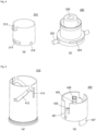
- FIG. 4 is a perspective view of a cap part and a pressurizing part of the cosmetic container according to the preferred embodiment of the present invention
- FIG. 5 is a perspective view of an elevation guide part and a pumping guide part of the cosmetic container according to the preferred embodiment of the present invention
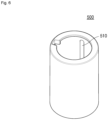
- FIG. 6 is a perspective view of a rotating part of the cosmetic container according to the preferred embodiment of the present invention.
- a cosmetic container 1000 includes a container body 100, a pump part 200, a button part 300, an elevation guide part 410, a pumping guide part 420, and a rotating part 500.
- the container body 100 can store contents therein.
- the contents may be, for instance, cosmetics, such as liquid-phase or gel-phase serum, essence, or cream, but is not limited to the above.
- the container body 100 may contain all kinds of materials which can be discharged by a pumping action, such as liquid-phase or gel-phase medical supplies or quasi drugs.
- a discharge part may be formed at the upper portion of the container body 100 in order to discharge the contents stored therein.
- the pump part 200 which will be described later, is combined with the discharge part of the container body 100.
- at least one screw thread is formed on the outer circumferential surface of the discharge part so as to be coupled with the pump part 200.
- the discharge part has a screw thread formed on the outer circumferential surface and the pump part 200 has a screw thread formed on the inner circumferential surface, so that the pump part 200 is arranged on the upper portion of the container body 100 by being screw-coupled with the discharge part.
- a piston (not shown), which ascends according to use of the contents may be arranged inside the container body 100.
- the pump part 200 is arranged on the upper portion of the container body 100, and performs the pumping action depending on the button being pressed or released and pulls up the contents stored in the container body 100 in order to discharge the contents out.
- a pump part 200 may be combined with the upper portion of the container body 100 through screw-coupling, but is not limited to the above, and may be combined with the container body 100 through various coupling structures.
- the pump part 200 can perform the pump action through various configurations known in the relevant fields.
- the button part 300 makes the pump part 200 perform the pumping action when a user presses or releases the button part 300.
- the cosmetic container 1000 according to the present invention may be changed into the first state where the button part 300 lowers and the discharge part 312 is accommodated in the rotating part 500 when the rotating part 500 is rotated or into the second state where the button part 300 is elevated completely and the discharge part 312 is exposed out of the rotating part 500. Therefore, only when the user wants to use the contents, the user can change the cosmetic container 1000 into the second state by rotating the rotating part 500, and then, presses the button part 300 to discharge the contents out.
- the button part 300 includes a cap part 310, a pressing part 320, and an elastic part 330.
- the cap part 310 is pressed or released by the user, and is coupled with the pressing part 320 while wrapping at least a part of the upper portion of the pressing part 320.
- the cap part 310 further includes one or more retaining grooves 314 formed on the outer circumferential surface of the cap part 310 so as to be coupled with the pressing part 320.
- the pressing part 320 is arranged inside the cap part 310.
- the pressing part 320 rotates together with the rotating part 500 to elevate or lower the button part 300. Furthermore, the pressing part 320 can transfer pressure to the pumping guide part 420 and the pump part 200.
- guide protrusions 322 protrude from both sides of the outer circumferential surface of the pressing part 320. Such guide protrusions 322 are inserted into coupling grooves 510 vertically formed in the inner surface of the rotating part 500, so that the pressing part 320 can rotate together with the rotating part 500. Additionally, the guide protrusions 322 are inserted into inclined guide grooves 412 of an elevation guide 410 in order to move along the inclined guide grooves 412 by rotation of the rotating part 500 and the pressing part 320, so that the button part 300 can be elevated and lowered.
- the guide protrusions 322 are arranged on tiered steps 423 of the pumping guide part, and presses the tiered steps 423 downwards when the user applies external force to the cap part 310, so that pressure can be transferred to the pumping guide part 420 and the pump part 200.
- the pressing part 320 has a content moving hole 326 perforated at the center thereof to be communicated with the discharge part 312 and/or the pump part 200, so that the contents can move to the discharge part 312.
- the pressing part 320 further has one or more retaining protrusions 324 formed on the outer circumferential surface of the pressing part 320 to correspond to the retaining grooves 314 of the cap part 310. Such retaining protrusions 324 are respectively inserted into the retaining grooves 314 of the cap part, so that the pressing part 320 is coupled with the cap part 310.
- the elastic part 330 is arranged between the cap part 310 and the pressing part 320 to generate elastic force upwards toward the cap part 310.
- the elastic part 330 is a spring, but is not limited to the spring and may be implemented through various materials having elasticity according to embodiments applied to the present invention.
- the button part 300 has a space formed therein to communicate with the discharge part 312 and the content moving hole 326.
- the upper surface of the inner face of the cap part 310 and the upper surface of the pressing part 320 are arranged to be spaced apart from each other at a predetermined interval by the elastic force of the elastic part 330, so that a space is formed between the cap part 310 and the pressing part 320.
- Such a space is communicated with the content moving hole 326 so as to form an inhalation space (s) inside the button part 300. That is, the inhalation space (s) is formed by the inside of the content moving hole 326 and the space communicating with the content moving hole 326, and the contents are accommodated in at least a part of the inhalation space (s).
- the inhalation space (s) may be decreased or increased in volume according to the user's pressurization and release to the button part 300. That is, when the user presses or releases the button part 300, the elastic part 330 is compressed or restored and the interval between the cap part 310 and the pressing part 320 is changed, so that the volume of the inhalation space (s) is decreased or increased. Therefore, the inhalation space (s) serves to inhale the contents remaining in the discharge part 312 after the contents are discharged.
- the change in volume of the inhalation space (s) depending on the user's pressurization and release may be limited within a predetermined range by the retaining grooves 314 and the retaining protrusions 324. That is, the retaining grooves 314 are formed to have a predetermined height, and the retaining protrusions 324 inserted into the retaining grooves 314 may be formed to be smaller in height or thickness than the retaining grooves 314. Accordingly, when the user presses or releases the cap part 310, the retaining protrusions 324 are relatively moved in the upward direction inside the retaining grooves 314 but are limited in movement distance by the retaining grooves 314.
- the cap part 310 can do a vertical movement within the limited range relative to the pressing part 320, so that the volume of the inhalation space (s) can be changed within a predetermined range.
- moving holes 316 in which the guide protrusions 322 are inserted are formed in the outer circumferential surface of the cap part 310.
- the height of the moving holes 316 is larger than the vertical thickness of the guide protrusion 322, so that the cap part 310 can move relative to the pressing part 320 when the cap part 310 is pressed ore released.
- the guide part 400 is arranged on the upper portion of the container body 100 to guide elevation of the button part 300 and to transfer pressure, which is generated by the pressed button part 300, to the pump part 200.
- the guide part 400 includes the elevation guide part 410 and the pumping guide part 420.
- the elevation guide part 410 is mounted above the container body 100 to surround the pump part 200.
- the elevation guide part 410 is fixed to the container body 100, and is not rotated together with the rotating part 500 when the rotating part 500 rotates relative to the container body 100.
- at least one fixing protrusion is formed on the outer circumferential surface of the pump part 200 combined with the upper portion of the container body 100, and a fixing groove corresponding to the fixing protrusion of the pump part 200 is formed in the inner circumferential surface of the elevation guide part 410.
- the fixing protrusion is coupled with the fixing groove, the elevation guide part 410 is fixed to the container body 100 to rotate relative to the rotating part 500.
- the rotating part 500 may be rotated relative to the elevation guide part 410 through various methods according to embodiments to which the present invention is applied.
- the elevation guide part 410 can guide elevation of the button part 300, especially, the pressing part 320, when the rotating part 500 rotates. So, guide grooves 412 and 414 may be formed in the outer circumferential surface of the elevation guide part 410 so that the guide protrusion 322 of the pressing part 320 is inserted into the guide grooves to be moved.
- the guide grooves 412 and 414 includes an inclined guide groove 412 and a vertical guide groove 414.
- the inclined guide grooves 412 guide elevation of the pressing part 320 according to rotation of the rotating part 500.
- the inclined guide grooves 412 may be formed by some area of the outer circumferential surface of the elevation guide part 410 being penetrated, and the guide protrusions 322 are inserted into the inclined guide grooves 412 to move along the inclined guide grooves 412.
- the inclined guide grooves 412 are formed in the circumferential direction from an area of the lower portion of the elevation guide part 410 to an area of the upper portion, and are inclined at a predetermined angle toward the upper portion of the elevation guide part 410.
- a pair of the inclined guide grooves 412 are formed at both sides of the outer circumferential surface of the elevation guide part 410 to correspond to each other so that the guide protrusions 322 can move stably.
- the present invention is not limited to the above, and the inclined guide grooves 412 may be implemented in various forms according to embodiments to which the present invention is applied.
- the vertical guide groove 414 may extend to a predetermined length downwardly from the upper end portion of the inclined guide groove 412.
- the pumping guide part 420 is arranged on the upper portion of the pump part 200, receives pressure from the button part 300 through the guide protrusion 322, and transfers it to the pump part 200. Additionally, the pumping guide part 420 is rotated together with the pressing part 320 or is rotated relative to the pressing part 320 according to rotation of the rotating part 500.
- Rotation guide grooves 421 and the tiered steps 423 are formed in the outer circumferential surface of the pumping guide part 420.
- the rotation guide groove 421 is formed in an area of the outer circumferential surface of the pumping guide part 420 in the longitudinal direction.
- the guide protrusion 322 is inserted into the rotation guide groove 421 so that the pumping guide part 420 and the pressing part 320 are rotated together when the rotating part 500 is rotated.
- the guide protrusion 322 vertically moves, namely, ascends along the rotation guide groove 421.
- the pumping guide part 420 and the pressing part 320 are relatively rotated till the guide protrusion 322 is located on the upper surface of the tiered step 423.
- the tiered step 423 is formed at one side of the rotation guide groove 421, when the button part 300 is pressed by the guide protrusion 322 in the second state, pressure for the pumping action is transferred to the pump part 200.
- the guide protrusion 322 gets out of the rotation guide groove 421 and is arranged above the tiered step 423 and the vertical guide groove 414.
- the tiered step 423 is pressed by the guide protrusion 322 and the pumping guide part 420 is moved downwards, so as to transfer pressure generated by pressurization of the cap part 310 to the pump part 200.
- an insertion part 425 inserted into the content moving hole 326 can extend upwards from the upper portion of the inside of the pumping guide part 420 to a predetermined length.
- the insertion part 425 has a hollow formed therein, and the content moving hole 326 and the pump part 200 are communicated with each other through the insertion part 425, so that the contents raised by the pumping action can be moved to the discharge part 312 through the content moving hole 326.
- a seal cap part 429 is coupled to the upper portion of the insertion part 425. Such a seal cap part 429 is inserted into the content moving hole 326, and the outer circumferential surface of the upper portion of the seal cap part 429 is arranged to get in contact with the inner circumferential surface of the content moving hole 326 in order to prevent the contents from getting out through a space formed between the content moving hole 326 and the insertion part 425.
- the insertion part 425 and the seal cap part 429 can be relatively lowered or elevated inside the content moving hole 326 when the cosmetic container 1000 is changed from the first state into the second state or from the second state into the first state. Therefore, the volume of the inhalation space (s) can be increased or decreased. Referring to FIG. 9 , the operation of the cosmetic container 1000 will be described in more detail.
- At least one extension part 427 is extended downwards from the lower portion of the pumping guide part 420.
- Such an extension part 427 can prevent the pumping action from being performed by the user's power in the first state that the button part 300 is lowered. That is, a support part 416 protrudes inwards from the inner circumferential surface of the elevation guide part 410 in correspondence to the extension part 427 of the pumping guide part 420, and the extension part 427 is arranged on the upper portion of the support part 416 in the first state, so as to prevent the pumping action from being performed even though the button part 300 is pressed. In the meantime, when the button part 300 is changed into the second state, the extension part 427 separated from the upper portion of the support part 416.
- the rotating part 500 is coupled to be rotated relatively while wrapping the elevation guide part 410 at the upper portion of the container body 100, so as to rotate in one direction or in the opposite direction by receiving rotary power from the user.
- the rotating part 500 transfers the rotary power to the pressing part 320 to rotate together with the pressing part 320.
- the coupling groove 510 in which the guide protrusion 322 of the pressing part 320 is inserted is vertically extended from the inner surface of the rotating part 500 to a predetermined length.
- the pressing part 320 can be increased or decreased since the guide protrusion 322 is moved vertically along the coupling groove 510.
- the rotating part 500 has an inner shape corresponding to the shape of the cap part 310 so that the discharge part 312 can get into or out of the rotating part 500 according to elevation or lowering of the button part 300.
- a limiting jaw (not shown) protrudes inwards on the inner surface of the rotating part 500, so that the lower surface of the discharge part 312 is seated on the limiting jaw in the first state. Therefore, even though the cap part 310 is pressed, it is prevented that the cap part 310 is moved vertically.
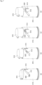
- FIG. 7 is a view showing an example of the operation of the cosmetic container according to the preferred embodiment of the present invention.
- FIG. 7 illustrates the action that the button part is rotated and/or elevated according to rotation of the rotating part and the cosmetic container is changed from the first state to the second state.
- the guide protrusion 322 of the pressing part 320 is arranged at the lower end portion of the inclined guide groove 412.
- the guide protrusion 322 moves upwards in the rotational direction along the inclined guide groove 412, and at the same time, is vertically moved relative to the coupling groove 510 of the rotating part 500 and the rotation guide groove 421 of the pumping guide part 420, so that the pressing part 320 and the button part 300 are elevated.
- the pumping guide part 420 is rotated together with the pressing part 320.
- the guide protrusion 322 is arranged on the upper end portion of the inclined guide groove 412.
- the guide protrusion 322 gets out of the rotation guide groove 421 of the pumping guide part 420, so that the pressing part 320 and the pumping guide part 420 can rotate relatively. Due to the relative rotation, the guide protrusion 322 makes horizontal movement in the rotational direction, and is arranged on the upper surface of the tiered step 423.
- the guide protrusion 322 gets in contact with a side wall (not shown) extending upwards from one side end portion of the tiered step 423, the guide protrusion 322 presses the side wall, so that the pressing part 320 and the pumping guide part 420 can rotate together.
- the button part 300 completes the change into the second state.
- the pressing part 320 and the pumping guide part 420 are rotated together, so that the guide protrusion 322 and the tiered step 423 can be arranged in the vertical guide groove 414 of the elevation guide part 410. Therefore, when the user presses the button part 300 exposed externally, pressure is transferred to the pumping guide part 420 and the pumping guide part 420 is lowered, so that the pumping action of the pump part 200 can be performed.
- FIG. 8 is a view showing another example of the operation of the cosmetic container according to the preferred embodiment of the present invention.
- FIG. 8 illustrates a process that the contents are discharged when the user presses the button part in the second state of the cosmetic container.
- the inhalation space (s) in the second state, if the user does not press the cap part 310, the inhalation space (s) has the maximum volume. In this instance, the contents are contained in the inhalation space (s), but the upper portion of the inhalation space (s) forms a remaining space or a remaining volume since the upper portion is not filled with the contents.
- the elastic part 330 is pressed, and the cap part 310 is lowered relative to the pressing part 320.
- the upper surface of the retaining protrusion 324 is caught to the retaining groove 314 by getting in contact with the retaining groove 314, so that the cap part 310 is lowered to a limited distance relative to the pressing part 320, and so, the volume of the inhalation space (s) is reduced.
- the inhalation space (s) is filled with the contents, so that the remaining space or remaining volume in the inhalation space (s) is removed.
- first pressurization and the second pressurization can be carried out continuously by just one pressing action.
- the cosmetic container 1000 is restored to the state of FIG. 8(a) .
- the volume of the inhalation space (s) inside the button part 300, which was decreased by the cap part 310 pressed is increased, so that the inhalation (suck-back) action to inhale the contents remaining in the discharge part 312 can be carried out.
- the contents are discharged, since the contents remaining in the discharge part 312 are inhaled, it can prevent a leakage of the contents.
- FIG. 9 is a view showing a further example of the operation of the cosmetic container according to the preferred embodiment of the present invention.
- FIG. 9(a) is a sectional view showing the second state where the button part is elevated
- FIG. 9(b) is a sectional view of the first state where the button part is lowered.
- the inhalation space (s) has the maximum volume in the second state, and the contents are contained in the inhalation space (s), but the upper portion of the inhalation space (s) has a remaining space or volume which is not filled with the contents.
- the pressing part 320 is lowered, so that the insertion part 425 and the seal cap part 429 are relatively elevated inside the content moving hole 326. Therefore, the inserted length of the insertion part 425 inserted into the content moving hole 326 is increased, and the volume of the inhalation space (s) is decreased.
- the volume of the inhalation space (s) which is decreased by the cosmetic container 1000 being changed into the first state is smaller than the remaining volume of the inhalation space (s) formed in the second state. Therefore, even though the cosmetic container 1000 is changed from the second state to the first state, it is prevented that the contents are discharged out through the discharge part 312 by decrease in the volume of the inhalation space (s).
- FIG. 10 is a view showing a still further example of the operation of the cosmetic container according to the preferred embodiment of the present invention.
- the user when the user does not use the cosmetics, the user can carry or store the cosmetic container 1000 after making the cosmetic container 1000 into the first state where the button part 300 is accommodated in the rotating part 500.
- the first state as described above, even though the button part 300 is pressed, since the pumping action of the pump part 200 is not carried out, the contents are not discharged out.
- the user rotates the rotating part 500 in one direction in order to change the cosmetic container 1000 into the second state where the button part 300 is elevated, so that the discharge part 312 is exposed out of the rotating part 500. Continuously, when the user presses the button part 300, the contents are discharged out by the pumping action of the pump part 200.
- the user rotates the rotating part 500 in the opposite direction, so that the cosmetic container is changed from the second state to the first state.
Landscapes
- Engineering & Computer Science (AREA)
- Mechanical Engineering (AREA)
- Containers And Packaging Bodies Having A Special Means To Remove Contents (AREA)
- Closures For Containers (AREA)
Claims (8)
- Kosmetikbehälter (1000) mit einem einziehbaren Knopf, umfassend:einen Behälterkörper (100), der mit einem Inhalt gefüllt ist;einen Pumpenteil (200), der am oberen Abschnitt des Behälterkörpers (100) dazu angeordnet ist, den Inhalt durch eine Pumphandlung nach außen auszugeben; undeinen Knopfteil (300), der am oberen Abschnitt des Pumpenteils (200) dazu angeordnet ist, die durch die Druck- und Freigabehandlung des Benutzers ausgeführte Pumphandlung zu realisieren, wobei der Knopfteil (300) einen Ausgabeteil (312) zum Ausgeben des Inhalts nach außen aufweist,wobei der Knopfteil (300) einen innerhalb des Knopfteils (300) ausgebildeten Einzugsraum (s) aufweist und der Einzugsraum (s) mit dem Ausgabeteil (312) in Verbindung steht und sein Volumen je nach Drücken und Freigeben des Knopfteils (300) vergrößert oder verkleinert wird, um den in dem Ausgabeteil (312) verbleibenden Inhalt einzuziehen,wobei der Knopfteil (300) ferner Folgendes umfasst:einen Deckelteil (310), der durch einen Benutzer gedrückt oder freigegeben wird und an dem an einer Seite der Ausgabeteil (312) ausgebildet ist;einen Drückteil (320), der innerhalb des Deckelteils (310) dazu angeordnet ist, durch den gedrückten Deckelteil (310) erzeugten Druck an den Pumpenteil (200) weiterzuleiten, und der eine Inhaltsbewegungsöffnung (326) aufweist, die dazu ausgebildet ist, eine Bewegung des Inhalts zu erlauben; undeinen elastischen Teil (330), der zwischen dem Deckelteil (310) und dem Drückteil (320) dazu angeordnet ist, eine Federkraft hin zu dem Deckelteil (310) zu erzeugen,wobei die innere obere Oberfläche des Deckelteils (310) und die obere Oberfläche des Drückteils (320) durch eine Federkraft des elastischen Teils (330) um einen vorbestimmten Abstand voneinander beabstandet sind und ein zwischen dem Deckelteil (310) und dem Drückteil (320) ausgebildeter Raum mit der Inhaltsbewegungsöffnung (326) derart in Verbindung steht, dass der Einzugsraum (s) zwischen dem Raum und einem Innenraum der Inhaltsbewegungsöffnung ausgebildet ist,wobei wenigstens ein Führungsvorsprung (322) von der äußeren Umfangsoberfläche des Drückteils (320) vorsteht undwobei der Kosmetikbehälter (1000) ferner Folgendes umfasst:einen Drehteil (500), der an den oberen Abschnitt des Behälterkörpers (100) dazu gekoppelt ist, relativ gedreht zu werden, und durch Empfangen von Drehkraft von dem Benutzer sich gemeinsam mit dem Drückteil (320) dreht;einen Hubführungsteil (410), der innerhalb des Drehteils (500) angeordnet ist und eine in der äußeren Umfangsoberfläche ausgebildete Führungsnut aufweist, wobei der Führungsvorsprung (322) des Drückteils in die Führungsnut derart eingeführt ist, dass der Hubführungsteil (410) je nach Drehung des Drehteils (500) ein Heben und Senken des Knopfteils (300) führt; undeinen Pumpenführungsteil (420), der an den Drückteil (320) dazu gekoppelt ist, sich gemeinsam mit dem Drückteil (320) zu drehen oder sich relativ zu dem Drückteil (320) zu drehen, und der Druck von dem Deckelteil (310) über den Führungsvorsprung (322) empfängt und den Druck an den Pumpenteil (200) weiterleitet, undwobei je nach Drehung des Drehteils (500) der Kosmetikbehälter (1000) in den ersten Zustand, in dem der Knopfteil (300) abgesenkt ist und der Ausgabeteil (312) in dem Drehteil (500) aufgenommen ist, oder in den zweiten Zustand, in dem der Knopfteil (300) angehoben ist und der Ausgabeteil (312) aus dem Drehteil (500) heraus frei liegt, gebracht wird.
- Kosmetikbehälter (1000) nach Anspruch 1, wobei wenigstens eine Haltenut (314) in der äußeren Umfangsoberfläche des Deckelteils (310) bis zu einer vorbestimmten Höhe ausgebildet ist und wenigstens ein Haltevorsprung (324) auf der äußeren Umfangsoberfläche des Drückteils (320) ausgebildet und in die Haltenut (314) eingeführt ist und
wobei der Haltevorsprung (324) des Drückteils (320) je nach Drücken und Freigeben des Deckelteils (310) vertikal und relativ innerhalb der Haltenut (314) bewegt wird und der vertikale Bewegungsabstand durch die Haltenut (314) derart begrenzt ist, dass das Volumen des Einzugsraums (s) innerhalb eines begrenzten Bereichs verändert wird. - Kosmetikbehälter (1000) nach Anspruch 1, wobei die Führungsnut eine schräge Führungsnut (412) und eine vertikale Führungsnut (414), die sich von einem Endabschnitt der schrägen Führungsnut (412) nach unten erstreckt, umfasst,wobei, wenn der Drehteil (500) gedreht wird, der Führungsvorsprung (322) sich entlang der schrägen Führungsnut (412) bewegt, um ein Anheben und Absenken des Drückteils (320) zu führen, undwobei, wenn der Führungsvorsprung (322) sich entlang der schrägen Führungsnut (412) bewegt und sich über der vertikalen Führungsnut (414) befindet, der Führungsvorsprung (322) sich vertikal entlang der vertikalen Führungsnut (414) dazu bewegt, eine Pumphandlung auszuführen, wenn der Knopfteil (300) gedrückt oder freigegeben wird.
- Kosmetikbehälter (1000) nach Anspruch 1, wobei eine Kopplungsnut (510), die dem Führungsvorsprung (322) entspricht, in der inneren Oberfläche des Drehteils (500) in einer vertikalen Richtung ausgebildet ist und der Führungsvorsprung (322) in die Kopplungsnut (510) derart eingeführt ist, dass der Drückteil (320) gemeinsam mit dem Drehteil (500) gedreht wird, und
wobei, wenn der Drehteil (500) sich dreht, der Führungsvorsprung (322) entlang der schrägen Führungsnut (412) bewegt wird und gleichzeitig vertikal entlang der Kopplungsnut (510) bewegt wird. - Kosmetikbehälter (1000) nach Anspruch 1, wobei eine Drehführungsnut (421), in welche der Führungsvorsprung (322) eingeführt ist, in der äußeren Umfangsoberfläche des Pumpführungsteils (420) derart ausgebildet ist, dass der Pumpführungsteil (420) gemeinsam mit dem Drückteil (320) gedreht wird, und
wobei eine abgestufte Stufe (423) an einer Seite der Drehführungsnut (421) dazu ausgebildet ist, durch den Führungsvorsprung (322) nach unten gedrückt zu werden, wenn der Knopfteil (300) gedrückt wird. - Kosmetikbehälter (1000) nach Anspruch 5, wobei, wenn der Drehteil (500) gedreht wird, der Pumpführungsteil (420) gemeinsam mit dem Drückteil (320) gedreht wird und, wenn der Knopfteil (300) angehoben wird, der Führungsvorsprung (322) sich aus der Drehführungsnut (421) löst und der Drückteil (320) relativ zu dem Pumpführungsteil (420) gedreht wird und
wobei, wenn der Drückteil (320) relativ gedreht wird, der Führungsvorsprung (322) an einer vorbestimmten Position der oberen Oberfläche der abgestuften Stufe (423) angeordnet ist und der Pumpführungsteil (420) gemeinsam mit dem Drückteil (320) derart gedreht wird, dass die abgestufte Stufe (423) in der vertikalen Führungsnut (414) angeordnet ist und der Pumpführungsteil (420) gemeinsam mit dem Drückteil (320) abgesenkt wird, wenn die abgestufte Stufe (423) und die vertikale Führungsnut (414) miteinander ausgerichtet sind und der Knopfteil (300) gedrückt wird. - Kosmetikbehälter (1000) nach Anspruch 5, wobei wenigstens ein Verlängerungsteil (427) sich von dem unteren Abschnitt des Pumpführungsteils (420) nach unten erstreckt und ein Stützteil (416), der dem Verlängerungsteil (427) entspricht, von der inneren Umfangsoberfläche des Hubführungsteils (410) nach innen vorsteht und
wobei, in dem ersten Zustand, der Verlängerungsteil (427) auf dem oberen Abschnitt des Stützteils (416) dazu angeordnet ist, von dem Stützteil (416) derart gestützt zu werden, dass eine Ausführung der Pumphandlung durch Drücken des Knopfteils (300) verhindert wird. - Kosmetikbehälter (1000) nach Anspruch 1, wobei, in dem zweiten Zustand, der Inhalt in wenigstens einem Abschnitt des Einzugsraums (s) enthalten ist und
wobei, wenn der zweite Zustand in den ersten Zustand übergeht, der Drückteil (320) relativ zu dem Pumpführungsteil (420) derart abgesenkt wird, dass das Volumen des Einzugsraums (s) verringert wird, und das verringerte Volumen des Einzugsraums (s) kleiner als das übrige Volumen des Einzugsraums (s) in dem zweiten Zustand ist, sodass verhindert wird, dass der Inhalt während des Übergangs von dem zweiten Zustand in den ersten Zustand ausläuft.
Applications Claiming Priority (2)
| Application Number | Priority Date | Filing Date | Title |
|---|---|---|---|
| KR1020190001679A KR102171859B1 (ko) | 2019-01-07 | 2019-01-07 | 버튼 출몰식 화장품 용기 |
| PCT/KR2019/018080 WO2020145543A1 (ko) | 2019-01-07 | 2019-12-19 | 버튼 출몰식 화장품 용기 |
Publications (3)
| Publication Number | Publication Date |
|---|---|
| EP3909463A1 EP3909463A1 (de) | 2021-11-17 |
| EP3909463A4 EP3909463A4 (de) | 2022-10-12 |
| EP3909463B1 true EP3909463B1 (de) | 2024-10-30 |
Family
ID=71520798
Family Applications (1)
| Application Number | Title | Priority Date | Filing Date |
|---|---|---|---|
| EP19909554.8A Active EP3909463B1 (de) | 2019-01-07 | 2019-12-19 | Kosmetikbehälter mit einem einziehbaren knopf |
Country Status (6)
| Country | Link |
|---|---|
| US (1) | US11559822B2 (de) |
| EP (1) | EP3909463B1 (de) |
| KR (1) | KR102171859B1 (de) |
| CN (1) | CN113271811B (de) |
| ES (1) | ES3002691T3 (de) |
| WO (1) | WO2020145543A1 (de) |
Families Citing this family (11)
| Publication number | Priority date | Publication date | Assignee | Title |
|---|---|---|---|---|
| KR20220051681A (ko) | 2020-10-19 | 2022-04-26 | 김용만 | 펌프 용기 |
| KR20220051688A (ko) | 2020-10-19 | 2022-04-26 | 김용만 | 펌프 용기 |
| KR20220051689A (ko) | 2020-10-19 | 2022-04-26 | 김용만 | 펌프 용기 |
| KR20220051685A (ko) | 2020-10-19 | 2022-04-26 | 김용만 | 펌프 용기 |
| KR102456614B1 (ko) * | 2021-01-15 | 2022-10-19 | 펌텍코리아(주) | 버튼의 승강 구조를 갖는 이중 화장품용기 |
| KR102409694B1 (ko) * | 2021-08-18 | 2022-06-16 | 맥센스 주식회사 | 긴급 대피용 산소마스크 |
| KR20230123139A (ko) * | 2022-02-16 | 2023-08-23 | (주)아모레퍼시픽 | 회전형 승하강용기 및 회전형 승하강용기의 작동방법 |
| KR102730461B1 (ko) * | 2022-03-08 | 2024-11-15 | (주)연우 | 내용물 용기 |
| CN115072168B (zh) * | 2022-07-26 | 2025-08-19 | 富祥塑胶制品(上海)有限公司 | 无弹簧式化妆品包装容器 |
| WO2024028688A1 (en) * | 2022-08-04 | 2024-02-08 | Pibiplast S.P.A. | Container of a product and relative dispensing method |
| KR102600967B1 (ko) | 2023-04-10 | 2023-11-10 | (주)새한화장품 | 자동 밀폐식 밸브를 구비한 디스펜싱 클로저 |
Family Cites Families (14)
| Publication number | Priority date | Publication date | Assignee | Title |
|---|---|---|---|---|
| US5549223A (en) * | 1994-08-03 | 1996-08-27 | Toyo Seikan Kaisha, Ltd. | Pump with back suction phase |
| KR200347811Y1 (ko) | 2003-12-05 | 2004-04-17 | 주식회사 태평양 | 출몰식 화장품 용기 |
| ATE552915T1 (de) * | 2005-07-29 | 2012-04-15 | Yoshino Kogyosho Co Ltd | Ausstossbehälter |
| KR200442431Y1 (ko) * | 2007-01-09 | 2008-11-10 | 주식회사 두코 | 분사식 화장품용기 |
| KR101267966B1 (ko) | 2011-05-24 | 2013-05-27 | (주)톨리코리아 | 출몰식 작동버튼을 가지는 에어리스 펌프 화장품용기 |
| KR101285861B1 (ko) * | 2012-02-14 | 2013-07-12 | 변재삼 | 에어리스 타입 화장품용기의 노즐개폐장치 |
| KR101388094B1 (ko) * | 2012-07-02 | 2014-04-23 | (주)연우 | 캡 일체형 펌핑식 화장품용기 |
| EP2859957B1 (de) * | 2013-10-14 | 2019-12-18 | Yonwoo Co., Ltd. | Kosmetikbehälter vom Pumpentyp mit integrierter Kappe |
| CN104544905B (zh) * | 2013-10-14 | 2017-09-01 | 株式会社衍宇 | 盖帽一体型抽吸式化妆品容器 |
| KR101501027B1 (ko) * | 2014-06-16 | 2015-03-12 | (주)연우 | 캡슐 토출용 펌프 용기 |
| KR101722531B1 (ko) * | 2014-12-31 | 2017-04-03 | (주)연우 | 버튼 출몰형 펌핑식 화장품 용기 |
| KR101750307B1 (ko) * | 2015-04-24 | 2017-06-23 | (주)연우 | 진공펌프가 구비된 크림타입 화장품용기 |
| KR101666683B1 (ko) * | 2015-09-18 | 2016-10-17 | (주)연우 | 버튼 출몰식 디스펜서 용기 |
| KR101959906B1 (ko) * | 2017-03-30 | 2019-07-15 | 펌텍코리아(주) | 잔여 내용물의 토출을 방지하는 화장품 용기 |
-
2019
- 2019-01-07 KR KR1020190001679A patent/KR102171859B1/ko active Active
- 2019-12-19 CN CN201980088098.1A patent/CN113271811B/zh active Active
- 2019-12-19 WO PCT/KR2019/018080 patent/WO2020145543A1/ko not_active Ceased
- 2019-12-19 EP EP19909554.8A patent/EP3909463B1/de active Active
- 2019-12-19 ES ES19909554T patent/ES3002691T3/es active Active
- 2019-12-19 US US17/421,044 patent/US11559822B2/en active Active
Also Published As
| Publication number | Publication date |
|---|---|
| KR102171859B1 (ko) | 2020-10-29 |
| KR20200085505A (ko) | 2020-07-15 |
| CN113271811B (zh) | 2024-06-18 |
| US11559822B2 (en) | 2023-01-24 |
| CN113271811A (zh) | 2021-08-17 |
| ES3002691T3 (en) | 2025-03-07 |
| EP3909463A1 (de) | 2021-11-17 |
| EP3909463A4 (de) | 2022-10-12 |
| WO2020145543A1 (ko) | 2020-07-16 |
| US20220097089A1 (en) | 2022-03-31 |
Similar Documents
| Publication | Publication Date | Title |
|---|---|---|
| US11559822B2 (en) | Cosmetic container having retractable button | |
| KR101666683B1 (ko) | 버튼 출몰식 디스펜서 용기 | |
| US5289818A (en) | Single-dose spray-dispenser for endonasal administration of liquid medicaments | |
| KR101789573B1 (ko) | 스포이드형 화장품 용기 | |
| US20130200106A1 (en) | Cosmetic container having release prevention device | |
| EP2904928A1 (de) | Geteilter kosmetikbehälter | |
| KR101406893B1 (ko) | 액체용기용 정량 토출장치 | |
| KR101218741B1 (ko) | 디스펜서 용기 | |
| KR101152159B1 (ko) | 액체용기용 정량 토출장치 | |
| US20180104711A1 (en) | Cream-type cosmetic container comprising vacuum pump | |
| US20170065055A1 (en) | Cream-Type Cosmetic Container Having Vacuum Pump | |
| US11338968B2 (en) | Fixed quantity discharge device for liquid container | |
| JP7391878B2 (ja) | システム、カートリッジ、及び方法 | |
| KR102272109B1 (ko) | 샴푸 용기용 펌프 디스펜서 | |
| JP4966966B2 (ja) | 液体製品の投与収容デバイス | |
| JP2013236828A (ja) | 定量引出可能なスポイト及びこれを備える化粧品容器 | |
| KR101218738B1 (ko) | 디스펜서 용기 | |
| US6889875B2 (en) | Taper well meter dose pump | |
| CA2551658A1 (en) | Method and device for filling the dosing chamber of an inhaler for the first time | |
| KR20230168067A (ko) | 회전형 펌프용기 | |
| KR102341616B1 (ko) | 샴푸 용기용 펌프 디스펜서 | |
| CN221713173U (zh) | 一种送药量可控的喷雾瓶 | |
| KR101888948B1 (ko) | 롤러타입의 화장액 용기 | |
| KR20200086124A (ko) | 도포부가 구비되어 있는 노즐을 포함하고 있는 디스펜서 | |
| JP2008523864A (ja) | 流体又は粘着物の投与装置 |
Legal Events
| Date | Code | Title | Description |
|---|---|---|---|
| STAA | Information on the status of an ep patent application or granted ep patent |
Free format text: STATUS: THE INTERNATIONAL PUBLICATION HAS BEEN MADE |
|
| PUAI | Public reference made under article 153(3) epc to a published international application that has entered the european phase |
Free format text: ORIGINAL CODE: 0009012 |
|
| STAA | Information on the status of an ep patent application or granted ep patent |
Free format text: STATUS: REQUEST FOR EXAMINATION WAS MADE |
|
| 17P | Request for examination filed |
Effective date: 20210805 |
|
| AK | Designated contracting states |
Kind code of ref document: A1 Designated state(s): AL AT BE BG CH CY CZ DE DK EE ES FI FR GB GR HR HU IE IS IT LI LT LU LV MC MK MT NL NO PL PT RO RS SE SI SK SM TR |
|
| DAV | Request for validation of the european patent (deleted) | ||
| DAX | Request for extension of the european patent (deleted) | ||
| A4 | Supplementary search report drawn up and despatched |
Effective date: 20220914 |
|
| RIC1 | Information provided on ipc code assigned before grant |
Ipc: B65D 33/16 20060101ALI20220908BHEP Ipc: B05B 11/00 20060101ALI20220908BHEP Ipc: B65D 83/00 20060101ALI20220908BHEP Ipc: A45D 40/26 20060101ALI20220908BHEP Ipc: A45D 34/04 20060101AFI20220908BHEP |
|
| REG | Reference to a national code |
Ref country code: DE Ref legal event code: R079 Free format text: PREVIOUS MAIN CLASS: A45D0034040000 Ipc: B05B0011100000 Ref country code: DE Ref legal event code: R079 Ref document number: 602019061331 Country of ref document: DE Free format text: PREVIOUS MAIN CLASS: A45D0034040000 Ipc: B05B0011100000 |
|
| GRAP | Despatch of communication of intention to grant a patent |
Free format text: ORIGINAL CODE: EPIDOSNIGR1 |
|
| STAA | Information on the status of an ep patent application or granted ep patent |
Free format text: STATUS: GRANT OF PATENT IS INTENDED |
|
| RIC1 | Information provided on ipc code assigned before grant |
Ipc: B65D 33/16 20060101ALI20240515BHEP Ipc: B05B 11/00 20060101ALI20240515BHEP Ipc: A45D 40/26 20060101ALI20240515BHEP Ipc: A45D 34/04 20060101ALI20240515BHEP Ipc: B05B 11/10 20230101AFI20240515BHEP |
|
| INTG | Intention to grant announced |
Effective date: 20240607 |
|
| GRAS | Grant fee paid |
Free format text: ORIGINAL CODE: EPIDOSNIGR3 |
|
| GRAA | (expected) grant |
Free format text: ORIGINAL CODE: 0009210 |
|
| STAA | Information on the status of an ep patent application or granted ep patent |
Free format text: STATUS: THE PATENT HAS BEEN GRANTED |
|
| AK | Designated contracting states |
Kind code of ref document: B1 Designated state(s): AL AT BE BG CH CY CZ DE DK EE ES FI FR GB GR HR HU IE IS IT LI LT LU LV MC MK MT NL NO PL PT RO RS SE SI SK SM TR |
|
| REG | Reference to a national code |
Ref country code: GB Ref legal event code: FG4D |
|
| REG | Reference to a national code |
Ref country code: CH Ref legal event code: EP |
|
| REG | Reference to a national code |
Ref country code: DE Ref legal event code: R096 Ref document number: 602019061331 Country of ref document: DE |
|
| REG | Reference to a national code |
Ref country code: IE Ref legal event code: FG4D |
|
| REG | Reference to a national code |
Ref country code: LT Ref legal event code: MG9D |
|
| REG | Reference to a national code |
Ref country code: NL Ref legal event code: MP Effective date: 20241030 |
|
| REG | Reference to a national code |
Ref country code: ES Ref legal event code: FG2A Ref document number: 3002691 Country of ref document: ES Kind code of ref document: T3 Effective date: 20250307 |
|
| PG25 | Lapsed in a contracting state [announced via postgrant information from national office to epo] |
Ref country code: HR Free format text: LAPSE BECAUSE OF FAILURE TO SUBMIT A TRANSLATION OF THE DESCRIPTION OR TO PAY THE FEE WITHIN THE PRESCRIBED TIME-LIMIT Effective date: 20241030 Ref country code: IS Free format text: LAPSE BECAUSE OF FAILURE TO SUBMIT A TRANSLATION OF THE DESCRIPTION OR TO PAY THE FEE WITHIN THE PRESCRIBED TIME-LIMIT Effective date: 20250228 Ref country code: PT Free format text: LAPSE BECAUSE OF FAILURE TO SUBMIT A TRANSLATION OF THE DESCRIPTION OR TO PAY THE FEE WITHIN THE PRESCRIBED TIME-LIMIT Effective date: 20250228 |
|
| PG25 | Lapsed in a contracting state [announced via postgrant information from national office to epo] |
Ref country code: NL Free format text: LAPSE BECAUSE OF FAILURE TO SUBMIT A TRANSLATION OF THE DESCRIPTION OR TO PAY THE FEE WITHIN THE PRESCRIBED TIME-LIMIT Effective date: 20241030 Ref country code: FI Free format text: LAPSE BECAUSE OF FAILURE TO SUBMIT A TRANSLATION OF THE DESCRIPTION OR TO PAY THE FEE WITHIN THE PRESCRIBED TIME-LIMIT Effective date: 20241030 |
|
| REG | Reference to a national code |
Ref country code: AT Ref legal event code: MK05 Ref document number: 1736405 Country of ref document: AT Kind code of ref document: T Effective date: 20241030 |
|
| PG25 | Lapsed in a contracting state [announced via postgrant information from national office to epo] |
Ref country code: BG Free format text: LAPSE BECAUSE OF FAILURE TO SUBMIT A TRANSLATION OF THE DESCRIPTION OR TO PAY THE FEE WITHIN THE PRESCRIBED TIME-LIMIT Effective date: 20241030 |
|
| PG25 | Lapsed in a contracting state [announced via postgrant information from national office to epo] |
Ref country code: NO Free format text: LAPSE BECAUSE OF FAILURE TO SUBMIT A TRANSLATION OF THE DESCRIPTION OR TO PAY THE FEE WITHIN THE PRESCRIBED TIME-LIMIT Effective date: 20250130 |
|
| PG25 | Lapsed in a contracting state [announced via postgrant information from national office to epo] |
Ref country code: LV Free format text: LAPSE BECAUSE OF FAILURE TO SUBMIT A TRANSLATION OF THE DESCRIPTION OR TO PAY THE FEE WITHIN THE PRESCRIBED TIME-LIMIT Effective date: 20241030 Ref country code: AT Free format text: LAPSE BECAUSE OF FAILURE TO SUBMIT A TRANSLATION OF THE DESCRIPTION OR TO PAY THE FEE WITHIN THE PRESCRIBED TIME-LIMIT Effective date: 20241030 Ref country code: GR Free format text: LAPSE BECAUSE OF FAILURE TO SUBMIT A TRANSLATION OF THE DESCRIPTION OR TO PAY THE FEE WITHIN THE PRESCRIBED TIME-LIMIT Effective date: 20250131 |
|
| PG25 | Lapsed in a contracting state [announced via postgrant information from national office to epo] |
Ref country code: PL Free format text: LAPSE BECAUSE OF FAILURE TO SUBMIT A TRANSLATION OF THE DESCRIPTION OR TO PAY THE FEE WITHIN THE PRESCRIBED TIME-LIMIT Effective date: 20241030 |
|
| PG25 | Lapsed in a contracting state [announced via postgrant information from national office to epo] |
Ref country code: RS Free format text: LAPSE BECAUSE OF FAILURE TO SUBMIT A TRANSLATION OF THE DESCRIPTION OR TO PAY THE FEE WITHIN THE PRESCRIBED TIME-LIMIT Effective date: 20250130 |
|
| PG25 | Lapsed in a contracting state [announced via postgrant information from national office to epo] |
Ref country code: SM Free format text: LAPSE BECAUSE OF FAILURE TO SUBMIT A TRANSLATION OF THE DESCRIPTION OR TO PAY THE FEE WITHIN THE PRESCRIBED TIME-LIMIT Effective date: 20241030 |
|
| PG25 | Lapsed in a contracting state [announced via postgrant information from national office to epo] |
Ref country code: MC Free format text: LAPSE BECAUSE OF FAILURE TO SUBMIT A TRANSLATION OF THE DESCRIPTION OR TO PAY THE FEE WITHIN THE PRESCRIBED TIME-LIMIT Effective date: 20241030 |
|
| PG25 | Lapsed in a contracting state [announced via postgrant information from national office to epo] |
Ref country code: DK Free format text: LAPSE BECAUSE OF FAILURE TO SUBMIT A TRANSLATION OF THE DESCRIPTION OR TO PAY THE FEE WITHIN THE PRESCRIBED TIME-LIMIT Effective date: 20241030 |
|
| PG25 | Lapsed in a contracting state [announced via postgrant information from national office to epo] |
Ref country code: EE Free format text: LAPSE BECAUSE OF FAILURE TO SUBMIT A TRANSLATION OF THE DESCRIPTION OR TO PAY THE FEE WITHIN THE PRESCRIBED TIME-LIMIT Effective date: 20241030 |
|
| PG25 | Lapsed in a contracting state [announced via postgrant information from national office to epo] |
Ref country code: RO Free format text: LAPSE BECAUSE OF FAILURE TO SUBMIT A TRANSLATION OF THE DESCRIPTION OR TO PAY THE FEE WITHIN THE PRESCRIBED TIME-LIMIT Effective date: 20241030 |
|
| PG25 | Lapsed in a contracting state [announced via postgrant information from national office to epo] |
Ref country code: SK Free format text: LAPSE BECAUSE OF FAILURE TO SUBMIT A TRANSLATION OF THE DESCRIPTION OR TO PAY THE FEE WITHIN THE PRESCRIBED TIME-LIMIT Effective date: 20241030 |
|
| PG25 | Lapsed in a contracting state [announced via postgrant information from national office to epo] |
Ref country code: CZ Free format text: LAPSE BECAUSE OF FAILURE TO SUBMIT A TRANSLATION OF THE DESCRIPTION OR TO PAY THE FEE WITHIN THE PRESCRIBED TIME-LIMIT Effective date: 20241030 |
|
| REG | Reference to a national code |
Ref country code: CH Ref legal event code: PL Ref country code: DE Ref legal event code: R097 Ref document number: 602019061331 Country of ref document: DE |
|
| PG25 | Lapsed in a contracting state [announced via postgrant information from national office to epo] |
Ref country code: LU Free format text: LAPSE BECAUSE OF NON-PAYMENT OF DUE FEES Effective date: 20241219 |
|
| PLBE | No opposition filed within time limit |
Free format text: ORIGINAL CODE: 0009261 |
|
| STAA | Information on the status of an ep patent application or granted ep patent |
Free format text: STATUS: NO OPPOSITION FILED WITHIN TIME LIMIT |
|
| PG25 | Lapsed in a contracting state [announced via postgrant information from national office to epo] |
Ref country code: SE Free format text: LAPSE BECAUSE OF FAILURE TO SUBMIT A TRANSLATION OF THE DESCRIPTION OR TO PAY THE FEE WITHIN THE PRESCRIBED TIME-LIMIT Effective date: 20241030 |
|
| 26N | No opposition filed |
Effective date: 20250731 |
|
| REG | Reference to a national code |
Ref country code: BE Ref legal event code: MM Effective date: 20241231 |
|
| PG25 | Lapsed in a contracting state [announced via postgrant information from national office to epo] |
Ref country code: BE Free format text: LAPSE BECAUSE OF NON-PAYMENT OF DUE FEES Effective date: 20241231 |
|
| PG25 | Lapsed in a contracting state [announced via postgrant information from national office to epo] |
Ref country code: CH Free format text: LAPSE BECAUSE OF NON-PAYMENT OF DUE FEES Effective date: 20241231 |
|
| PG25 | Lapsed in a contracting state [announced via postgrant information from national office to epo] |
Ref country code: IE Free format text: LAPSE BECAUSE OF NON-PAYMENT OF DUE FEES Effective date: 20241219 |
|
| PGFP | Annual fee paid to national office [announced via postgrant information from national office to epo] |
Ref country code: DE Payment date: 20251022 Year of fee payment: 7 |
|
| PGFP | Annual fee paid to national office [announced via postgrant information from national office to epo] |
Ref country code: GB Payment date: 20251030 Year of fee payment: 7 |
|
| PGFP | Annual fee paid to national office [announced via postgrant information from national office to epo] |
Ref country code: IT Payment date: 20251121 Year of fee payment: 7 |
|
| PGFP | Annual fee paid to national office [announced via postgrant information from national office to epo] |
Ref country code: FR Payment date: 20251008 Year of fee payment: 7 |
|
| PGFP | Annual fee paid to national office [announced via postgrant information from national office to epo] |
Ref country code: ES Payment date: 20260119 Year of fee payment: 7 |