EP3907406A1 - Vakuumpumpe - Google Patents
Vakuumpumpe Download PDFInfo
- Publication number
- EP3907406A1 EP3907406A1 EP21168848.6A EP21168848A EP3907406A1 EP 3907406 A1 EP3907406 A1 EP 3907406A1 EP 21168848 A EP21168848 A EP 21168848A EP 3907406 A1 EP3907406 A1 EP 3907406A1
- Authority
- EP
- European Patent Office
- Prior art keywords
- holweck
- vacuum pump
- stator
- axial
- inlet
- Prior art date
- Legal status (The legal status is an assumption and is not a legal conclusion. Google has not performed a legal analysis and makes no representation as to the accuracy of the status listed.)
- Granted
Links
Images




Classifications
-
- F—MECHANICAL ENGINEERING; LIGHTING; HEATING; WEAPONS; BLASTING
- F04—POSITIVE - DISPLACEMENT MACHINES FOR LIQUIDS; PUMPS FOR LIQUIDS OR ELASTIC FLUIDS
- F04D—NON-POSITIVE-DISPLACEMENT PUMPS
- F04D19/00—Axial-flow pumps
- F04D19/02—Multi-stage pumps
- F04D19/04—Multi-stage pumps specially adapted to the production of a high vacuum, e.g. molecular pumps
- F04D19/044—Holweck-type pumps
-
- F—MECHANICAL ENGINEERING; LIGHTING; HEATING; WEAPONS; BLASTING
- F04—POSITIVE - DISPLACEMENT MACHINES FOR LIQUIDS; PUMPS FOR LIQUIDS OR ELASTIC FLUIDS
- F04D—NON-POSITIVE-DISPLACEMENT PUMPS
- F04D19/00—Axial-flow pumps
- F04D19/02—Multi-stage pumps
- F04D19/022—Multi-stage pumps with concentric rows of vanes
Definitions
- the invention relates to a vacuum pump, in particular a turbo-molecular vacuum pump, with at least one inlet, one outlet and at least two Holweck stages that are concentric with respect to a common axis of rotation and that follow one another in the pumping direction between the inlet and the outlet.
- Vacuum pumps are used in various fields of technology. Depending on the requirements, the vacuum pumps have one or more pump stages.
- a Holweck pump stage (also referred to here simply as a Holweck stage) belongs to the genus of molecular vacuum pumps and generates a molecular flow through the rotation of a rotating element relative to a static element.
- a vacuum pump can comprise one or more Holweck stages, with several Holweck stages being able to pump both in series and in parallel with one another.
- Holweck stages are typically used in turbo-molecular vacuum pumps and are usually arranged downstream of one or more turbo-molecular pump stages (also known as turbo-pumping stages).
- a Holweck stage comprises a Holweck rotor and a Holweck stator segment, the Holweck rotor having a rotor shaft to which one or more Holweck sleeves (often also referred to as rotor sleeves) are concentrically attached by means of a disc-shaped Holweck hub, for example.
- the Holweck stator segment is provided with a single or multiple Holweck thread. The gas molecules to be conveyed are conveyed by the rotating movement of the Holweck sleeve relative to the Holweck stator segment assigned to it along the threads from an inlet side to an outlet side.
- a thread usually includes a through Circumferential Holweck canal delimited by walls of a web, in which the gas molecules are conveyed when the rotor sleeve rotates relative to the Holweck stator segment.
- the width of the radial gap (Holweck gap) between the outside of the Holweck stator segment or the web tip diameter of the Holweck stator thread and the rotor sleeve must be kept small.
- Two successive Holweck stages can include a common Holweck stator, which is provided on both sides with a Holweck thread, hereinafter also referred to as "double-sided" and protrudes into the radial space between the concentrically arranged Holweck sleeves .
- the two Holweck stator segments of the two Holweck stages are thus arranged on both sides of the Holweck stator.
- an axial distance or axial gap between the axial end of the Holweck stator and the Holweck hub is kept as small as possible.
- the power consumption is an important parameter when integrating a vacuum pump into a system.
- a large part of the power consumption is often caused by the gas friction in the Holweck stage (s).
- an axial distance between an axial end protruding into the gap between at least one of the Holweck stator segments and the Holweck hub is greater than 25% of the axial extent of a section of the Holweck stator segments protruding into the radial gap and / or greater than 25% of the axial Extension of at least one of the Holweck sleeves is.
- the axial distance can also be selected to be greater and greater than 30%, 40% or 50% of the axial extent of the section of the Holweck stator segments protruding into the radial gap and / or greater than 30%, 40% or 50% of the axial extent of at least one of the Holweck sleeves.
- the Holweck stator segments and the Holweck sleeves can be designed such that an axial extension of a section protruding into the radial interspace of at least one of the Holweck stator segments is less than 75% of the axial extension of at least one of the Holweck sleeves.
- the axial extent of the protruding into the radial gap Section of at least one of the Holweck stator segments can, if necessary, also be smaller than 70%, 60% or 50% of the axial extent of at least one of the Holweck sleeves.
- the components of the Holweck stator that are provided with a Holweck thread and protrude into the radial space between the Holweck or rotor sleeves - in order to significantly reduce the power consumption of the vacuum pump to reach.
- the rotating elements of the Holweck steps do not have to be changed.
- a Holweck stator with shortened, pump-active Holweck stator segments can be used in a conventional vacuum pump without structural changes to the rotating elements of the Holweck stages having to be made.
- a comparatively simple modification consequently already achieves the desired goal.
- the Holweck stator segments and the Holweck sleeves are designed and / or arranged in such a way that the axial distance between an axial end of the two Holweck stator segments protruding into the space and the rotor hub is greater than 25%, 30%, 40% or 50% of the axial extent of a
- the section of the Holweck stator segments protruding into the space and / or greater than 25%, 30%, 40% or 50% of the axial extension of both Holweck sleeves and / or that the axial extension of the section of the two Holweck stator segments protruding into the space is less than 80%, 70 %, 60% or 50% of the axial extent is at least one of the Holweck sleeves.
- the two Holweck stator segments of the two Holweck stages can have a different or the same axial extent. The same applies to the Holweck sleeves.
- the vacuum pump can have at least a first and a second inlet, the first inlet being assigned to a turbomolecular pumping stage and the second inlet being assigned to the Holweck stages.
- the concept according to the invention is particularly advantageous, since in this way an adaptation to the actual pump power requirement that exists at the second inlet can take place and at the same time the power consumption caused by the Holweck stages is reduced.
- the second inlet - viewed in the axial direction of the vacuum pump - is arranged in the area of the Holweck stages.
- the second inlet can be a radial inlet, as a result of which a compact design is achieved.
- the outer of the two Holweck sleeves can form a third Holweck stage together with a (third) Holweck stator segment which surrounds the outer Holweck sleeve radially on the outside at least in sections.
- the Holweck stator segment of the third Holweck stage has a recess or opening which forms the second inlet.
- the Holweck stator can be provided with at least one heat exchanger element which extends from the axial end of the Holweck stator protruding into the radial interspace towards the rotor hub.
- the axial gap enlarged according to the invention, is thus used to provide a heat exchanger element that improves the heat management of the vacuum pump and is not pump-active.
- the heat exchanger element Since the heat exchanger element has no relevant active pumping effect, it does not lead to any relevant increase in the power consumption of the vacuum pump.
- the heat exchanger element can be rod-shaped, sleeve-shaped or partially sleeve-shaped. It can have an opening or a slot in order to improve the heat transfer between the gas flow and the element.
- the at least one heat exchanger element is detachably connected to the Holweck stator, for example by screwing. This makes it possible to utilize the axial gap in a suitable manner and to adapt the heat exchange in the area of the Holweck steps as required.
- the Holweck stator can be arranged in various positions in the axial direction. It can be provided that the axial position of the Holweck stator can be changed continuously or in discrete steps.
- a fastening concept is conceivable that allows the Holweck stator to be fixed in positions that are introduced into the radial gap between the Holweck sleeves at different depths.
- the Holweck stator then does not have to be exchanged or changed in order to achieve a needs-based adaptation of the Holweck stages.
- the vacuum pump has an adjustment mechanism with which an axial positioning of the Holweck stator and / or at least one of the Holweck stator segments can be adjusted.
- the vacuum pump can have a control device which controls the setting mechanism, for example on the basis of an operator input, an operating mode of the vacuum pump and / or an operating parameter of the vacuum pump. Adjusting the axial The Holweck stator can be positioned automatically - that is, without input from an operator.
- At least one of the Holweck stator segments is formed in one piece with the Holweck stator. This preferably applies to both Holweck stator segments. In principle, however, it is also conceivable that one of the two segments or both segments is or are detachably connected to a base body of the Holweck stator. For an adaptation of the Holweck stages that is suitable for the respective application, the entire stator then does not have to be exchanged, but an adaptation can be made by exchanging one or both segments.
- the present invention further relates to a vacuum pump system comprising a vacuum pump according to at least one of the embodiments described above and at least one replacement Holweck stator which comprises at least one Holweck stator segment which has an axial extent that deviates from the axial extent of the corresponding Holweck stator segment of the Holweck stator.
- at least one replacement Holweck stator segment can be provided which has an axial extent that deviates from the axial extent of the corresponding Holweck stator segment of the Holweck stator.
- the system can also comprise a plurality of replacement Holweck stators which have differently configured and / or dimensioned Holweck stator segments.
- the replacement Holweck stators thus form a set that makes it easy to modify the vacuum pump as required. The same applies analogously to a set of replacement Holweckstatoregmenten.
- the turbo molecular pump 111 shown comprises a pump inlet 115 which is surrounded by an inlet flange 113 and to which a recipient (not shown) can be connected in a manner known per se.
- the gas from the recipient can be sucked out of the recipient via the pump inlet 115 and conveyed through the pump to a pump outlet 117 to which a backing pump, such as a rotary vane pump, can be connected.
- the inlet flange 113 forms according to FIG Fig. 1 the upper end of the housing 119 of the vacuum pump 111.
- the housing 119 comprises a lower part 121 on which an electronics housing 123 is arranged laterally. Electrical and / or electronic components of the vacuum pump 111 are accommodated in the electronics housing 123, for example for operating an electric motor 125 arranged in the vacuum pump (see also FIG Fig. 3 ).
- a plurality of connections 127 for accessories are provided on the electronics housing 123.
- a data interface 129 for example in accordance with the RS485 standard, and a power supply connection 131 are arranged on the electronics housing 123.
- turbo-molecular pumps that do not have an electronic housing attached in this way, but are connected to external drive electronics.
- a flood inlet 133 in particular in the form of a flood valve, is provided on the housing 119 of the turbo molecular pump 111, via which the vacuum pump 111 can be flooded.
- a sealing gas connection 135, which is also referred to as a purge gas connection via which purge gas is used to protect the electric motor 125 (see e.g. Fig. 3 ) can be admitted into the engine compartment 137, in which the electric motor 125 in the vacuum pump 111 is accommodated, before the gas conveyed by the pump.
- Two coolant connections 139 are also arranged in the lower part 121, one of the coolant connections being provided as an inlet and the other coolant connection being provided as an outlet for coolant, which can be passed into the vacuum pump for cooling purposes.
- Other existing turbo-molecular vacuum pumps (not shown) are operated exclusively with air cooling.
- the lower side 141 of the vacuum pump can serve as a standing surface, so that the vacuum pump 111 can be operated standing on the lower side 141.
- the vacuum pump 111 can, however, also be attached to a recipient via the inlet flange 113 and can thus be operated in a suspended manner, as it were.
- the vacuum pump 111 can be designed in such a way that it can also be put into operation when it is oriented in a different way than in FIG Fig. 1 is shown.
- Embodiments of the vacuum pump can also be implemented in which the underside 141 cannot be arranged facing downwards, but facing to the side or facing upwards. In principle, any angle is possible.
- various screws 143 are also arranged by means of which components of the vacuum pump not specified here are attached to one another.
- a bearing cap 145 is attached to the underside 141.
- Fastening bores 147 are also arranged on the underside 141, via which the pump 111 can be fastened to a support surface, for example. This is not possible with other existing turbo molecular vacuum pumps (not shown), which are in particular larger than the pump shown here.
- a coolant line 148 is shown, in which the coolant introduced and discharged via the coolant connections 139 can circulate.
- the vacuum pump comprises several process gas pump stages for conveying the process gas present at the pump inlet 115 to the pump outlet 117.
- a rotor 149 is arranged in the housing 119 and has a rotor shaft 153 rotatable about an axis of rotation 151.
- the turbo-molecular pump 111 comprises several turbo-molecular pump stages connected in series with one another with several radial rotor disks 155 fastened to the rotor shaft 153 and stator disks 157 arranged between the rotor disks 155 and fixed in the housing 119.
- a rotor disk 155 and an adjacent stator disk 157 each form a turbomolecular one Pumping stage.
- the stator disks 157 are held at a desired axial distance from one another by spacer rings 159.
- the vacuum pump also comprises Holweck pump stages which are arranged one inside the other in the radial direction and are connected in series with one another for effective pumping. There are other turbo-molecular vacuum pumps (not shown) that do not have Holweck pump stages.
- the rotor of the Holweck pump stages comprises a rotor hub 161 arranged on the rotor shaft 153 and two cylinder-jacket-shaped Holweck rotor sleeves 163, 165 which are attached to the rotor hub 161 and carried by the latter, which are oriented coaxially to the axis of rotation 151 and nested in one another in the radial direction. Furthermore, two cylinder jacket-shaped Holweck stator sleeves 167, 169 are provided, which are also oriented coaxially to the axis of rotation 151 and, viewed in the radial direction, are nested inside one another.
- the active pumping surfaces of the Holweck pump stages are formed by the jacket surfaces, that is to say by the radial inner and / or outer surfaces, of the Holweck rotor sleeves 163, 165 and the Holweck stator sleeves 167, 169.
- the radial inner surface of the outer Holweck stator sleeve 167 lies opposite the radial outer surface of the outer Holweck rotor sleeve 163 with the formation of a radial Holweck gap 171 and with this forms the first Holweck pump stage following the turbomolecular pumps.
- the radial inner surface of the outer Holweck rotor sleeve 163 faces the radial outer surface of the inner Holweck stator sleeve 169 with the formation of a radial Holweck gap 173 and forms with this a second Holweck pumping stage.
- the radial inner surface of the inner Holweck stator sleeve 169 lies opposite the radial outer surface of the inner Holweck rotor sleeve 165 with the formation of a radial Holweck gap 175 and with this forms the third Holweck pumping stage.
- a radially running channel can be provided, via which the radially outer Holweck gap 171 is connected to the central Holweck gap 173.
- a radially running channel can be provided at the upper end of the inner Holweck stator sleeve 169, via which the middle Holweck gap 173 is connected to the radially inner Holweck gap 175.
- a connecting channel 179 to the outlet 117 can also be provided at the lower end of the radially inner Holweck rotor sleeve 165.
- the aforementioned pump-active surfaces of the Holweck stator sleeves 167, 169 each have a plurality of Holweck grooves running helically around the axis of rotation 151 in the axial direction, while the opposite lateral surfaces of the Holweck rotor sleeves 163, 165 are smooth and the gas for operating the Drive vacuum pump 111 in the Holweck grooves.
- a roller bearing 181 is provided in the area of the pump outlet 117 and a permanent magnetic bearing 183 in the area of the pump inlet 115.
- a conical injection molded nut 185 is provided on the rotor shaft 153 with an outer diameter that increases towards the roller bearing 181.
- the injection-molded nut 185 is in sliding contact with at least one stripper of an operating medium reservoir.
- an injection screw can be provided instead of an injection nut. Since different designs are thus possible, the term "spray tip" is also used in this context.
- the operating medium reservoir comprises several absorbent disks 187 stacked on top of one another, which are impregnated with an operating medium for the roller bearing 181, e.g. with a lubricant.
- the operating medium is transferred by capillary action from the operating medium reservoir via the scraper to the rotating injection nut 185 and, as a result of the centrifugal force, is conveyed along the injection nut 185 in the direction of the increasing outer diameter of the injection nut 185 to the roller bearing 181, where it eg fulfills a lubricating function.
- the roller bearing 181 and the operating medium store are enclosed in the vacuum pump by a trough-shaped insert 189 and the bearing cover 145.
- the permanent magnetic bearing 183 comprises a rotor-side bearing half 191 and a stator-side bearing half 193, each of which comprises a ring stack of several permanent magnetic rings 195, 197 stacked on top of one another in the axial direction.
- the ring magnets 195, 197 are opposite one another with the formation of a radial bearing gap 199, the rotor-side ring magnets 195 being arranged radially on the outside and the stator-side ring magnets 197 being arranged radially on the inside are.
- the magnetic field present in the bearing gap 199 causes magnetic repulsive forces between the ring magnets 195, 197, which cause the rotor shaft 153 to be supported radially.
- the rotor-side ring magnets 195 are carried by a carrier section 201 of the rotor shaft 153 which surrounds the ring magnets 195 radially on the outside.
- the stator-side ring magnets 197 are carried by a stator-side support section 203 which extends through the ring magnets 197 and is suspended from radial struts 205 of the housing 119.
- the ring magnets 195 on the rotor side are fixed parallel to the axis of rotation 151 by a cover element 207 coupled to the carrier section 201.
- the stator-side ring magnets 197 are fixed parallel to the axis of rotation 151 in one direction by a fastening ring 209 connected to the carrier section 203 and a fastening ring 211 connected to the carrier section 203.
- a plate spring 213 can also be provided between the fastening ring 211 and the ring magnet 197.
- An emergency or retainer bearing 215 is provided within the magnetic bearing, which runs empty during normal operation of the vacuum pump 111 without contact and only comes into engagement with an excessive radial deflection of the rotor 149 relative to the stator to create a radial stop for the rotor 149 to form so that a collision of the rotor-side structures with the stator-side structures is prevented.
- the backup bearing 215 is designed as an unlubricated roller bearing and forms a radial gap with the rotor 149 and / or the stator, which has the effect that the backup bearing 215 is disengaged during normal pumping operation.
- the radial deflection at which the backup bearing 215 engages is dimensioned large enough that the backup bearing 215 does not come into engagement during normal operation of the vacuum pump, and at the same time small enough that a collision of the rotor-side structures with the stator-side structures under all circumstances is prevented.
- the vacuum pump 111 comprises the electric motor 125 for rotatingly driving the rotor 149.
- the armature of the electric motor 125 is formed by the rotor 149, the rotor shaft 153 of which extends through the motor stator 217.
- a permanent magnet arrangement can be arranged radially on the outside or embedded on the section of the rotor shaft 153 extending through the motor stator 217.
- the motor stator 217 is fixed in the housing within the motor compartment 137 provided for the electric motor 125.
- a sealing gas which is also referred to as a flushing gas and which can be air or nitrogen, for example, can enter the engine compartment 137 via the sealing gas connection 135.
- the electric motor 125 can be protected from process gas, e.g. from corrosive components of the process gas, via the sealing gas.
- the engine compartment 137 can also be evacuated via the pump outlet 117, i.e. the vacuum pressure produced by the backing pump connected to the pump outlet 117 is at least approximately in the engine compartment 137.
- a so-called and known labyrinth seal 223 can also be provided between the rotor hub 161 and a wall 221 delimiting the engine compartment 137, in particular to achieve better sealing of the motor compartment 217 from the Holweck pump stages located radially outside.
- a Holweck arrangement according to the invention as shown below by way of example with reference to FIG Figures 6 to 9 is described, can in particular instead of the Holweck arrangement of the above with reference to Figs. 1 to 5 described vacuum pump are used.
- FIGS. 6 to 9 show only the right part of a Holweck arrangement 11 of a vacuum pump, for example a turbo-molecular pump, with three Holweck stages A, B, C.
- the vacuum pump comprises a rotor shaft 15 which is rotatably mounted about an axis of rotation 13. which carries two cylindrical, concentrically arranged rotor sleeves 19.
- the internal Holweck stator 21, positioned between the two rotor sleeves 19, is designed on both sides in the manner according to the invention, ie. H. Provided on both sides with a Holweck stator segment 25a, 25b.
- the segments 25a, 25b each have a pump-active Holweck thread.
- the segments 25a, 25b can be formed in one piece with the Holweck stator 21. For example, grooves forming Holweck thread are introduced into a base body of the stator 21. However, it is also entirely conceivable to manufacture the segments 25a, 25b as separate components that are attached to the base body in order to form the stator 21.
- the outer Holweck stator 23 Radially outside of the outer rotor sleeve 19 is the outer Holweck stator 23, which can be formed, for example, by the pump housing or is connected to it.
- the outer Holweck stator 23 and the outer rotor sleeve 19 form the first Holweck stage A.
- the outer rotor sleeve 19 also forms the second Holweck stage B with the Holweck stator segment 25a, which is also referred to here as the outer pump or Holweck stage.
- the inner rotor sleeve 19 and the Holweck stator segment 25b form the third Holweck stage C, which is also referred to here as the inner pump or Holweck stage.
- FIG. 1 Arrows indicate the pumping direction and thus the conveying direction of the gas molecules conveyed in Holweck stages A, B, C.
- the pumping direction runs from an inlet 33 of the Holweck arrangement 11 to an outlet 35.
- the Holweck stators 21, 23 are also designed in the shape of a sleeve and are arranged coaxially to one another and to the rotor sleeves 19.
- the Holweck stator 21 protrudes into a radial space between the Holweck sleeves 19.
- An axial end of the Holweck segment 25a, 25b corresponds to the axial end of the stator 21 in the present example and is arranged at an axial distance X from the rotor hub 17.
- X axial distance from the rotor hub 17.
- the distance X is significantly greater, both when this distance X is set in relation to the axial extent of the sections of the Holweck stator segments 25a, 25b protruding into the space and in relation to the axial extent of the Holweck sleeves 19 (each significantly greater than 25%) . It also applies that the axial extent of the Holweck stator segments 25a, 25b protruding into the radial space between the sleeves 19 is significantly smaller than 75% of the axial extent of the Holweck sleeves 19.
- the comparatively large distance X according to the invention leads - compared with conventional Holweck arrangements - to a surprisingly greatly reduced power consumption of the arrangement 11 with approximately equally good or only slightly reduced vacuum data.
- Fig. 7 shows modifications of the in Fig. 6 shown concept.
- the Holweck stator 23 here has a radial opening which forms the inlet 33 of the arrangement 11.
- the inlet 33 can be an intermediate inlet of a split-flow pump. It goes without saying that the Holweck stator 23 can also be omitted so that gas molecules to be conveyed enter the pump-active part of the arrangement 11 in an area between the sleeve 19 and a base 37 to which the Holweck stator 21 is connected.
- Fig. 7 also shows an example of an optional measure with which a heat transfer in the area of the Holweck arrangement 11 can be improved.
- a heat exchanger element 39 is arranged at the axial end of the Holweck stator 21. It can be designed in one piece with the Holweck stator 21. Alternatively, it is also possible for element 39 to be releasably fastened to stator 21, for example by screwing.
- a plurality of elements 39 are preferably provided, which are arranged in a uniformly distributed manner, in particular in the circumferential direction of the sleeve-shaped stator 21.
- the element 39 can be a rod. However, it is also conceivable to provide a sleeve-shaped heat exchanger element 39 at the axial end of the stator 21. It is also conceivable to provide only partial sections of the axial end of the stator 21 with curved surfaces which follow the sleeve shape of the stator 21 in sections (partial sleeves).
- the element 39 can have perforations and / or slots.
- Fig. 8 shows a Holweck stator 21 which is provided with Holweck stator segments 25a, 25b which have different axial extensions.
- the axial end of the stator 21 protrudes beyond the axial end of the segments 25a, 25b.
- the power consumption of the arrangement 11 is compared with the power consumption of the arrangement 11 according to FIG Fig. 6 reduced.
- the reduction in power consumption is brought about by increasing the distance X 'or X "between the rotor hub 17 and the axial end of the active pumping segments 25a and 25b.
- the embodiment according to Fig. 8 is only intended to convey, by way of example, that not only by changing the axial extent of the stator 21 (that is to say by a pure axial shortening of the stator 21 according to FIG Fig. 6 ) but also by changing the axial extent of the segments 25a, 25b, the power consumption of the arrangement 11 can be influenced.
- a change in the power consumption can be achieved not only by replacing the stator 21 or the Holweck stator segments 25a, 25b, but also by changing the axial position of the stator 21.
- a Holweck stator 21 is used, which is geometrically essentially like the stator 21 of Fig. 6 is trained. However, it was moved downwards in the axial direction and fixed in this position, as a result of which an increased distance X '"is established between the rotor hub 17 and the axial end of the stator 21.
- a corresponding fixing mechanism can be designed in such a way that the axial position of the stator 21 can be changed in discrete steps or continuously.
- the axial position of the stator 21 can be set manually, either directly or by means of an adjusting mechanism 41.
- a control device 43 is provided with which the adjusting mechanism 41 can be controlled.
- a control of the mechanism 41 can for example take place on the basis of an operator input, an operating mode of the vacuum pump and / or an operating parameter of the vacuum pump.
- the Holweck stator segments 25a, 25b are arranged to be displaceable in the axial direction and / or can be fixed in various axial positions (directly or by means of a corresponding mechanism) to allow for the axial extent of the active pump Modify areas of Holweck stages B, C and thus also the power consumption associated with them.
Landscapes
- Engineering & Computer Science (AREA)
- Mechanical Engineering (AREA)
- General Engineering & Computer Science (AREA)
- Non-Positive Displacement Air Blowers (AREA)
Abstract
Description
- Die Erfindung betrifft eine Vakuumpumpe, insbesondere Turbomolekularvakuumpumpe, mit zumindest einem Einlass, einem Auslass und wenigstens zwei bezüglich einer gemeinsamen Rotationsachse konzentrischen, in Pumprichtung zwischen dem Einlass und dem Auslass aufeinanderfolgenden Holweckstufen.
- Vakuumpumpe werden in verschiedenen Gebieten der Technik eingesetzt. Je nach Anforderung weisen die Vakuumpumpen ein oder mehrere Pumpstufen auf. Eine Holweck-Pumpstufe (hier auch einfach als Holweckstufe bezeichnet) gehört zur Gattung der Molekularvakuumpumpen und erzeugt durch die Drehung eines rotierenden Elements relativ zu einem statischen Element eine molekulare Strömung. Eine Vakuumpumpe kann eine oder mehrere Holweckstufen umfassen, wobei mehrere Holweckstufen sowohl seriell als auch parallel zueinander pumpen können. Holweckstufen werden typischerweise in Turbomolekularvakuumpumpen eingesetzt und sind in der Regel einer oder mehreren Turbomolekularpumpstufen (auch Turbopumpstufen) nachgeordnet.
- Wie vorstehend bereits kurz erwähnt wurde, umfasst eine Holweckstufe einen Holweckrotor und ein Holweckstatorsegment, wobei der Holweckrotor eine Rotorwelle aufweist, an welche mittels einer z.B. scheibenförmigen Holwecknabe eine oder mehrere Holweckhülsen (oft auch als Rotorhülsen bezeichnet) konzentrisch angebracht sind. Das Holweckstatorsegment ist mit einem ein- oder mehrgängigen Holweckgewinde versehen. Die zu fördernden Gasmoleküle werden durch die rotierende Bewegung der Holweckhülse relativ zu dem ihr zugeordneten Holweckstatorsegment entlang der Gewindegänge von einer Einlassseite zu einer Auslassseite gefördert. Ein Gewindegang umfasst üblicherweise einen durch Wände eines Steges begrenzten umlaufenden Holweckkanal, in welchem die Gasmoleküle gefördert werden, wenn sich die Rotorhülse relativ zu dem Holweckstatorsegment dreht. Um Rückströmverluste zu minimieren, muss die Weite des radialen Spalts (Holweckspalt) zwischen der Außenseite des Holweckstatorsegments bzw. des Stegspitzendurchmessers des Holweckstatorgewindes und der Rotorhülse klein gehalten werden.
- Es sind sogenannte "gefaltete" Holweck-Anordnungen bekannt, bei denen mehrere Holweckstufen konzentrisch ineinander angeordnet sind, sodass die Pumpeinrichtungen von radial unmittelbar aufeinanderfolgenden Holweckstufen einander entgegengesetzt sind. Zwei aufeinanderfolgende Holweckstufen, eine (radial) äußere Holweckstufe und eine (radial) innere Holweckstufe, können einen gemeinsamen, beidseitig mit einem Holweckgewinde versehenen, im Folgenden auch als "doppelseitig" bezeichneten Holweckstator umfassen, der in den radialen Zwischenraum zwischen den konzentrisch angeordneten Holweckhülsen ragt. Die beiden Holweckstatorsegmente der beiden Holweckstufen sind somit beidseitig an dem Holweckstator angeordnet.
- Um eine Vakuumpumpe in axialer Richtung möglichst kompakt zu bauen, wird ein axialer Abstand oder axialer Zwischenraum zwischen dem axialen Ende des Holweckstators und der Holwecknabe möglichst klein gehalten. Zwischen den beiden genannten Komponenten liegt bei herkömmlichen gefalteten Holweck-Anordnungen somit in der Regel lediglich ein schmaler Ringspalt vor, der ebenfalls dazu beiträgt, Rückströmverluste zwischen den Holweckstufen zu minimieren.
- In vielen Anwendungsfällen ist die Leistungsaufnahme eine wichtige Größe bei der Integration einer Vakuumpumpe in ein System. Beispielsweise wird bei einer herkömmlichen Turbomolekularvakuumpumpe mit Turbopumpstufe(n) und Holweckstufe(n) oftmals ein Großteil der Leistungsaufnahme durch die Gasreibung in der oder den Holweckstufe(n) verursacht.
- Erfindungsgemäß wurde erkannt, dass im Bereich der Holweck-Anordnung Potential besteht, die Leistungsaufnahme der Vakuumpumpe zu beeinflussen, ohne entscheidende Leistungsparameter, wie etwa Saugvermögen oder Vorvakuumverträglichkeit der Pumpe, zu kompromittieren.
- Ausgehend von einer bekannten Vakuumpumpe mit den Merkmalen des Oberbegriffs des Anspruchs 1 ist entgegen den üblichen Konstruktionsprinzipien bewusst ein vergleichsweise groß dimensionierter axialer Abstand oder Zwischenraum zwischen dem statischen Element der aufeinanderfolgenden Holweckstufen und der Rotornabe vorgesehen.
- Konkret wird dies dadurch erreicht, dass ein axialer Abstand zwischen einem in den Zwischenraum ragenden axialen Ende zumindest eines der Holweckstatorsegmente und der Holwecknabe größer als 25% der axialen Erstreckung eines in den radialen Zwischenraum ragenden Abschnitts der Holweckstatorsegmente und/oder größer als 25% der axialen Erstreckung zumindest einer der Holweckhülsen ist. Der axiale Abstand kann bei einem Bedarf nach einer größeren Leistungsaufnahmereduktion auch größer gewählt werden und größer als 30%, 40% oder 50% der axialen Erstreckung des in den radialen Zwischenraum ragenden Abschnitts der Holweckstatorsegmente sein und/oder größer als 30%, 40% oder 50% der axialen Erstreckung zumindest einer der Holweckhülsen sein.
- Alternativ oder zusätzlich kann können die Holweckstatorsegmente und die Holweckhülsen derart ausgestaltet sein, dass eine axiale Erstreckung eines in den radialen Zwischenraum ragenden Abschnitts zumindest eines der Holweckstatorsegmente kleiner als 75% der axialen Erstreckung zumindest einer der Holweckhülsen ist. Bei einer solchen Ausgestaltung der genannten Komponenten ergibt sich der vorstehend beschriebene vergleichsweise große axiale Abstand oder axiale Zwischenraum. Die axiale Erstreckung des in den radialen Zwischenraum ragenden Abschnitts zumindest einer der Holweckstatorsegmente kann bei Bedarf auch kleiner als 70%, 60% oder 50% der axialen Erstreckung zumindest einer der Holweckhülsen sein.
- Dem vorstehend beschriebenen Konzept liegt die Erkenntnis zugrunde, dass die Leistungsaufnahme der Vakuumpumpe von der effektiven (pumpaktiven) axialen Länge der Holweckstufen abhängt. Vereinfacht gesagt ist die Leistungsaufnahme desto höher, je größer die axiale Länge des pumpaktiven Bereichs der Holweckstufen ist.
- In manchen Anwendungsfällen ist es nicht erforderlich, die volle Pumpleistung der Holweckstufen abzurufen oder bereitzustellen.
- Erfindungsgemäß wird daher vorgeschlagen, die axiale Erstreckung der Holweckstatorsegmente zu reduzieren, um den vorstehend definierten axialen Abstand zu vergrößern. Die Leistungsaufnahme der Vakuumpumpe wird dadurch deutlich reduziert, ohne dass z. B. deren Saugvermögen oder Vorvakuumverträglichkeit (Vakuumsdaten) übermäßig beeinflusst wird. Da erfindungsgemäß erkannt wurde, dass trotz des vorstehend beschriebenen vergleichsweise groß dimensionierten axialen Zwischenraums, der durch eine geeignete und vorstehend definierte Dimensionierung der hierfür relevanten Komponenten erzielt wird, annähernd vergleichbare oder nur geringfügig und für bestimmte Fälle vollkommen ausreichende Leistungsdaten der Pumpe erreicht werden, können bereits erprobte Vakuumpumpenkonzepte angepasst werden, ohne dass komplexe bauliche Änderungen erforderlich sind. Es muss lediglich eine Reduzierung der pumpaktiv wirksamen axialen Erstreckung der Holweckstatorsegmente - also der Komponenten des Holweckstators, die mit einem Holweckgewinde versehen sind und in den radialen Zwischenraum zwischen den Holweck- oder Rotorhülsen ragen - vorgenommen werden, um eine deutliche Reduzierung der Leistungsaufnahme der Vakuumpumpe zu erreichen. Die rotierenden Elemente der Holweckstufen müssen dabei nicht verändert werden.
- Beispielsweise kann in eine herkömmliche Vakuumpumpe ein Holweckstator mit verkürzten pumpaktiven Holweckstatorsegmenten eingesetzt werden, ohne dass bauliche Veränderungen an den rotierenden Elementen der Holweckstufen genommen werden müssen. Durch eine vergleichsweise einfache Modifikation wird folglich bereits das angestrebte Ziel erreicht.
- Insbesondere wurde erkannt, dass eine Vergrößerung des axialen Zwischenraums die Vakuumdaten in geringerem Maße negativ beeinflusst als erwartet und gleichzeitig der positive Effekt der Leistungsaufnahmereduktion überproportional zu Buche schlägt.
- Weitere Ausführungsformen der Erfindung sind in der Beschreibung, den Ansprüchen und den beigefügten Zeichnungen angegeben.
- Gemäß einer Ausführungsform sind die Holweckstatorsegmente und die Holweckhülsen derart ausgestaltet und/oder angeordnet, dass der axialer Abstand zwischen einem in den Zwischenraum ragenden axialen Ende beider Holweckstatorsegmente und der Rotornabe größer als 25%, 30%, 40% oder 50% der axialen Erstreckung eines in den Zwischenraum ragenden Abschnitts der Holweckstatorsegmente und/oder größer als 25%, 30%, 40% oder 50% der axialen Erstreckung beider Holweckhülsen ist und/oder dass die axiale Erstreckung des in den Zwischenraum ragenden Abschnitts beider Holweckstatorsegmente kleiner als 80%, 70%, 60% oder 50% der axialen Erstreckung zumindest einer der Holweckhülsen ist.
- Ganz grundsätzlich gilt, dass die beiden Holweckstatorsegmente der beiden Holweckstufen eine unterschiedliche oder die gleiche axiale Erstreckung aufweisen können. Gleiches gilt für die Holweckhülsen.
- Die Vakuumpumpe kann zumindest einen ersten und einen zweiten Einlass aufweisen, wobei der erste Einlass einer turbomolekularen Pumpstufe zugeordnet ist und der zweite Einlass den Holweckstufen zugeordnet ist. Bei sogenannten Spliflow-Pumpen ist das erfindungsgemäße Konzept besonders vorteilhaft, da so auf einfache Weise eine Anpassung an den tatsächlichen Pumpleistungsbedarf, der an dem zweiten Einlass besteht, erfolgen kann und gleichzeitig die durch die Holweckstufen hervorgerufene Leistungsaufnahme reduziert wird.
- Beispielsweise ist der zweite Einlass - in axialer Richtung der Vakuumpumpe gesehen - im Bereich der Holweckstufen angeordnet.
- Der zweite Einlass kann ein radialer Einlass sein, wodurch eine kompakte Bauweise erreicht wird.
- Die die äußere der beiden Holweckhülsen kann zusammen mit einem die äußere Holweckhülse radial außenseitig zumindest abschnittsweise umgebenden (dritten) Holweckstatorsegment eine dritte Holweckstufe bilden. Insbesondere weist das Holweckstatorsegment der dritten Holweckstufe eine Ausnehmung oder Öffnung auf, die den zweiten Einlass bildet.
- Zur Verbesserung der Wärmeabfuhr im Bereich der Holweckstufen kann der Holweckstator mit zumindest einem Wärmetauscherelement versehen sein, das sich von dem in den radialen Zwischenraum ragenden axialen Ende des Holweckstators zu der Rotornabe hin erstreckt. Der erfindungsgemäß vergrößerte axiale Zwischenraum wird somit zur Bereitstellung eines das Wärmemanagement der Vakuumpumpe verbessernden, nicht pumpaktiven Wärmetauscherelements genutzt.
- Da das Wärmetauscherelement keine relevante pumpaktive Wirkung hat, führt es zu keiner relevanten Erhöhung der Leistungsaufnahme der Vakuumpumpe.
- Das Wärmetauscherelement kann stäbchenförmig, hülsenförmig oder teilhülsenförmig ausgebildet sein. Es kann eine Durchbrechung oder einen Schlitz aufweisen, um den Wärmeübergang zwischen dem Gasstrom und dem Element zu verbessern.
- Mehr Flexibilität wird erlangt, wenn das zumindest eine Wärmetauscherelement lösbar mit dem Holweckstator verbunden ist, beispielsweise durch Verschrauben. Dadurch ist es möglich, den axialen Zwischenraum in geeigneter Weise auszunutzen und den Wärmeaustausch im Bereich der Holweckstufen bedarfsgerecht anzupassen.
- Der Holweckstator kann in axialer Richtung in verschiedenen Positionen anordbar sein. Es kann vorgesehen sein, dass die axiale Position des Holweckstators kontinuierlich oder in diskreten Schritten veränderbar ist.
- Beispielsweise ist ein Befestigungskonzept denkbar, dass es gestattet, den Holweckstator in unterschiedlich tief in den radialen Zwischenraum zwischen den Holweckhülsen eingebrachten Positionen zu fixieren. Der Holweckstator muss dann nicht ausgetauscht oder verändert werden, um eine bedarfsgerechte Anpassung der Holweckstufen zu erzielen.
- Gemäß einer Ausführungsform weist die Vakuumpumpe einen Einstellmechanismus, mit dem eine axiale Positionierung des Holweckstator und/oder zumindest eines der Holweckstatorsegmente einstellbar ist. Die Vakuumpumpe kann eine Steuereinrichtung aufweisen, die den Einstellmechanismus steuert, beispielsweise auf Basis einer Bedienereingabe, eines Betriebsmodus der Vakuumpumpe und/oder eines Betriebsparameters der Vakuumpumpe. Die Einstellung der axialen Positionierung des Holweckstators kann automatisch - d.h. ohne Eingabe eines Bedienpersonals - erfolgen.
- Gemäß einer weiteren Ausführungsform ist zumindest eines der Holweckstatorsegmente einstückig mit dem Holweckstator ausgebildet. Bevorzugt trifft dies auf beide Holweckstatorsegmente zu. Grundsätzlich ist es aber auch denkbar, dass eines der beiden Segmente oder beide Segmente lösbar mit einem Grundkörper des Holweckstators verbunden ist bzw. sind. Für eine für den jeweiligen Anwendungsfall geeignete Anpassung der Holweckstufen muss dann nicht der gesamte Stator ausgetauscht werden, sondern eine Anpassung kann durch einen Austausch eines oder beider Segmente erfolgen.
- Die vorliegende Erfindung betrifft ferner ein Vakuumpumpensystem umfassend eine Vakuumpumpe gemäß zumindest einer der vorstehend beschriebenen Ausführungsformen und zumindest einen Austausch-Holweckstator, der zumindest ein Holweckstatorsegment umfasst, das eine axiale Erstreckung aufweist, die von der axialen Erstreckung des entsprechenden Holweckstatorsegments des Holweckstators abweicht. Bei einer Ausführungsform mit zumindest einem lösbar an einem Grundkörper des Holweckstators befestigten Holweckstatorsegment kann zumindest ein Austausch-Holweckstatorsegment bereitgestellt werden, das eine axiale Erstreckung aufweist, die von der axialen Erstreckung des entsprechenden Holweckstatorsegments des Holweckstators abweicht.
- Das System kann auch mehrere Austausch-Holweckstatoren umfassen, die unterschiedlich konfigurierte und/oder dimensionierte Holweckstatorsegmente aufweisen. Die Austausch-Holweckstatoren bilden somit einen Satz, der es auf einfache Weise ermöglicht, die Vakuumpumpe bedarfsgerecht zu modifizieren. Gleiches gilt in analoger Form für einen Satz von Austausch-Holweckstatorsegmenten.
- Nachfolgend wird die Erfindung beispielhaft anhand vorteilhafter Ausführungsformen unter Bezugnahme auf die beigefügten Figuren beschrieben. Es zeigen, jeweils schematisch:
- Fig. 1
- eine perspektivische Ansicht einer Turbomolekularpumpe,
- Fig. 2
- eine Ansicht der Unterseite der Turbomolekularpumpe von
Fig. 1 , - Fig. 3
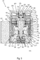
- einen Querschnitt der Turbomolekularpumpe längs der in
Fig. 2 gezeigten Schnittlinie A-A, - Fig. 4
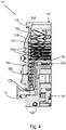
- eine Querschnittsansicht der Turbomolekularpumpe längs der in
Fig. 2 gezeigten Schnittlinie B-B, - Fig. 5
- eine Querschnittsansicht der Turbomolekularpumpe längs der in
Fig. 2 gezeigten Schnittlinie C-C, - Fig. 6
- schematisch einen Längsschnitt durch die rechte Seite einer Holweck-Anordnung gemäß einer ersten Ausführungsform der Erfindung und
- Fig. 7 bis 9
- schematisch einen Längsschnitt durch die rechte Seite einer Holweck-Anordnung gemäß weiterer Ausführungsformen der Erfindung.
- Die in
Fig. 1 gezeigte Turbomolekularpumpe 111 umfasst einen von einem Einlassflansch 113 umgebenen Pumpeneinlass 115, an welchen in an sich bekannter Weise ein nicht dargestellter Rezipient angeschlossen werden kann. Das Gas aus dem Rezipienten kann über den Pumpeneinlass 115 aus dem Rezipienten gesaugt und durch die Pumpe hindurch zu einem Pumpenauslass 117 gefördert werden, an den eine Vorvakuumpumpe, wie etwa eine Drehschieberpumpe, angeschlossen sein kann. - Der Einlassflansch 113 bildet bei der Ausrichtung der Vakuumpumpe gemäß
Fig. 1 das obere Ende des Gehäuses 119 der Vakuumpumpe 111. Das Gehäuse 119 umfasst ein Unterteil 121, an welchem seitlich ein Elektronikgehäuse 123 angeordnet ist. In dem Elektronikgehäuse 123 sind elektrische und/oder elektronische Komponenten der Vakuumpumpe 111 untergebracht, z.B. zum Betreiben eines in der Vakuumpumpe angeordneten Elektromotors 125 (vgl. auchFig. 3 ). Am Elektronikgehäuse 123 sind mehrere Anschlüsse 127 für Zubehör vorgesehen. Außerdem sind eine Datenschnittstelle 129, z.B. gemäß dem RS485-Standard, und ein Stromversorgungsanschluss 131 am Elektronikgehäuse 123 angeordnet. - Es existieren auch Turbomolekularpumpen, die kein derartiges angebrachtes Elektronikgehäuse aufweisen, sondern an eine externe Antriebselektronik angeschlossen werden.
- Am Gehäuse 119 der Turbomolekularpumpe 111 ist ein Fluteinlass 133, insbesondere in Form eines Flutventils, vorgesehen, über den die Vakuumpumpe 111 geflutet werden kann. Im Bereich des Unterteils 121 ist ferner noch ein Sperrgasanschluss 135, der auch als Spülgasanschluss bezeichnet wird, angeordnet, über welchen Spülgas zum Schutz des Elektromotors 125 (siehe z.B.
Fig. 3 ) vor dem von der Pumpe geförderten Gas in den Motorraum 137, in welchem der Elektromotor 125 in der Vakuumpumpe 111 untergebracht ist, eingelassen werden kann. Im Unterteil 121 sind ferner noch zwei Kühlmittelanschlüsse 139 angeordnet, wobei einer der Kühlmittelanschlüsse als Einlass und der andere Kühlmittelanschluss als Auslass für Kühlmittel vorgesehen ist, das zu Kühlzwecken in die Vakuumpumpe geleitet werden kann. Andere existierende Turbomolekularvakuumpumpen (nicht dargestellt) werden ausschließlich mit Luftkühlung betrieben. - Die untere Seite 141 der Vakuumpumpe kann als Standfläche dienen, sodass die Vakuumpumpe 111 auf der Unterseite 141 stehend betrieben werden kann. Die Vakuumpumpe 111 kann aber auch über den Einlassflansch 113 an einem Rezipienten befestigt werden und somit gewissermaßen hängend betrieben werden. Außerdem kann die Vakuumpumpe 111 so gestaltet sein, dass sie auch in Betrieb genommen werden kann, wenn sie auf andere Weise ausgerichtet ist als in
Fig. 1 gezeigt ist. Es lassen sich auch Ausführungsformen der Vakuumpumpe realisieren, bei der die Unterseite 141 nicht nach unten, sondern zur Seite gewandt oder nach oben gerichtet angeordnet werden kann. Grundsätzlich sind dabei beliebige Winkel möglich. - Andere existierende Turbomolekularvakuumpumpen (nicht dargestellt), die insbesondere größer sind als die hier dargestellte Pumpe, können nicht stehend betrieben werden.
- An der Unterseite 141, die in
Fig. 2 dargestellt ist, sind noch diverse Schrauben 143 angeordnet, mittels denen hier nicht weiter spezifizierte Bauteile der Vakuumpumpe aneinander befestigt sind. Beispielsweise ist ein Lagerdeckel 145 an der Unterseite 141 befestigt. - An der Unterseite 141 sind außerdem Befestigungsbohrungen 147 angeordnet, über welche die Pumpe 111 beispielsweise an einer Auflagefläche befestigt werden kann. Dies ist bei anderen existierenden Turbomolekularvakuumpumpen (nicht dargestellt), die insbesondere größer sind als die hier dargestellte Pumpe, nicht möglich.
- In den
Figuren 2 bis 5 ist eine Kühlmittelleitung 148 dargestellt, in welcher das über die Kühlmittelanschlüsse 139 ein- und ausgeleitete Kühlmittel zirkulieren kann. - Wie die Schnittdarstellungen der
Figuren 3 bis 5 zeigen, umfasst die Vakuumpumpe mehrere Prozessgaspumpstufen zur Förderung des an dem Pumpeneinlass 115 anstehenden Prozessgases zu dem Pumpenauslass 117. - In dem Gehäuse 119 ist ein Rotor 149 angeordnet, der eine um eine Rotationsachse 151 drehbare Rotorwelle 153 aufweist.
- Die Turbomolekularpumpe 111 umfasst mehrere pumpwirksam miteinander in Serie geschaltete turbomolekulare Pumpstufen mit mehreren an der Rotorwelle 153 befestigten radialen Rotorscheiben 155 und zwischen den Rotorscheiben 155 angeordneten und in dem Gehäuse 119 festgelegten Statorscheiben 157. Dabei bilden eine Rotorscheibe 155 und eine benachbarte Statorscheibe 157 jeweils eine turbomolekulare Pumpstufe. Die Statorscheiben 157 sind durch Abstandsringe 159 in einem gewünschten axialen Abstand zueinander gehalten.
- Die Vakuumpumpe umfasst außerdem in radialer Richtung ineinander angeordnete und pumpwirksam miteinander in Serie geschaltete Holweck-Pumpstufen. Es existieren andere Turbomolekularvakuumpumpen (nicht dargestellt), die keine Holweck-Pumpstufen aufweisen.
- Der Rotor der Holweck-Pumpstufen umfasst eine an der Rotorwelle 153 angeordnete Rotornabe 161 und zwei an der Rotornabe 161 befestigte und von dieser getragene zylindermantelförmige Holweck-Rotorhülsen 163, 165, die koaxial zur Rotationsachse 151 orientiert und in radialer Richtung ineinander geschachtelt sind. Ferner sind zwei zylindermantelförmige Holweck-Statorhülsen 167, 169 vorgesehen, die ebenfalls koaxial zu der Rotationsachse 151 orientiert und in radialer Richtung gesehen ineinander geschachtelt sind.
- Die pumpaktiven Oberflächen der Holweck-Pumpstufen sind durch die Mantelflächen, also durch die radialen Innen- und/oder Außenflächen, der Holweck-Rotorhülsen 163, 165 und der Holweck-Statorhülsen 167, 169 gebildet. Die radiale Innenfläche der äußeren Holweck-Statorhülse 167 liegt der radialen Außenfläche der äußeren Holweck-Rotorhülse 163 unter Ausbildung eines radialen Holweck-Spalts 171 gegenüber und bildet mit dieser die der Turbomolekularpumpen nachfolgende erste Holweck-Pumpstufe. Die radiale Innenfläche der äußeren Holweck-Rotorhülse 163 steht der radialen Außenfläche der inneren Holweck-Statorhülse 169 unter Ausbildung eines radialen Holweck-Spalts 173 gegenüber und bildet mit dieser eine zweite Holweck-Pumpstufe. Die radiale Innenfläche der inneren Holweck-Statorhülse 169 liegt der radialen Außenfläche der inneren Holweck-Rotorhülse 165 unter Ausbildung eines radialen Holweck-Spalts 175 gegenüber und bildet mit dieser die dritte Holweck-Pumpstufe.
- Am unteren Ende der Holweck-Rotorhülse 163 kann ein radial verlaufender Kanal vorgesehen sein, über den der radial außenliegende Holweck-Spalt 171 mit dem mittleren Holweck-Spalt 173 verbunden ist. Außerdem kann am oberen Ende der inneren Holweck-Statorhülse 169 ein radial verlaufender Kanal vorgesehen sein, über den der mittlere Holweck-Spalt 173 mit dem radial innenliegenden Holweck-Spalt 175 verbunden ist. Dadurch werden die ineinander geschachtelten Holweck-Pumpstufen in Serie miteinander geschaltet. Am unteren Ende der radial innenliegenden Holweck-Rotorhülse 165 kann ferner ein Verbindungskanal 179 zum Auslass 117 vorgesehen sein.
- Die vorstehend genannten pumpaktiven Oberflächen der Holweck-Statorhülsen 167, 169 weisen jeweils mehrere spiralförmig um die Rotationsachse 151 herum in axialer Richtung verlaufende Holweck-Nuten auf, während die gegenüberliegenden Mantelflächen der Holweck-Rotorhülsen 163, 165 glatt ausgebildet sind und das Gas zum Betrieb der Vakuumpumpe 111 in den Holweck-Nuten vorantreiben.
- Zur drehbaren Lagerung der Rotorwelle 153 sind ein Wälzlager 181 im Bereich des Pumpenauslasses 117 und ein Permanentmagnetlager 183 im Bereich des Pumpeneinlasses 115 vorgesehen.
- Im Bereich des Wälzlagers 181 ist an der Rotorwelle 153 eine konische Spritzmutter 185 mit einem zu dem Wälzlager 181 hin zunehmenden Außendurchmesser vorgesehen. Die Spritzmutter 185 steht mit mindestens einem Abstreifer eines Betriebsmittelspeichers in gleitendem Kontakt. Bei anderen existierenden Turbomolekularvakuumpumpen (nicht dargestellt) kann anstelle einer Spritzmutter eine Spritzschraube vorgesehen sein. Da somit unterschiedliche Ausführungen möglich sind, wird in diesem Zusammenhang auch der Begriff "Spritzspitze" verwendet.
- Der Betriebsmittelspeicher umfasst mehrere aufeinander gestapelte saugfähige Scheiben 187, die mit einem Betriebsmittel für das Wälzlager 181, z.B. mit einem Schmiermittel, getränkt sind.
- Im Betrieb der Vakuumpumpe 111 wird das Betriebsmittel durch kapillare Wirkung von dem Betriebsmittelspeicher über den Abstreifer auf die rotierende Spritzmutter 185 übertragen und in Folge der Zentrifugalkraft entlang der Spritzmutter 185 in Richtung des größer werdenden Außendurchmessers der Spritzmutter 185 zu dem Wälzlager 181 hin gefördert, wo es z.B. eine schmierende Funktion erfüllt. Das Wälzlager 181 und der Betriebsmittelspeicher sind durch einen wannenförmigen Einsatz 189 und den Lagerdeckel 145 in der Vakuumpumpe eingefasst.
- Das Permanentmagnetlager 183 umfasst eine rotorseitige Lagerhälfte 191 und eine statorseitige Lagerhälfte 193, welche jeweils einen Ringstapel aus mehreren in axialer Richtung aufeinander gestapelten permanentmagnetischen Ringen 195, 197 umfassen. Die Ringmagnete 195, 197 liegen einander unter Ausbildung eines radialen Lagerspalts 199 gegenüber, wobei die rotorseitigen Ringmagnete 195 radial außen und die statorseitigen Ringmagnete 197 radial innen angeordnet sind. Das in dem Lagerspalt 199 vorhandene magnetische Feld ruft magnetische Abstoßungskräfte zwischen den Ringmagneten 195, 197 hervor, welche eine radiale Lagerung der Rotorwelle 153 bewirken. Die rotorseitigen Ringmagnete 195 sind von einem Trägerabschnitt 201 der Rotorwelle 153 getragen, welcher die Ringmagnete 195 radial außenseitig umgibt. Die statorseitigen Ringmagnete 197 sind von einem statorseitigen Trägerabschnitt 203 getragen, welcher sich durch die Ringmagnete 197 hindurch erstreckt und an radialen Streben 205 des Gehäuses 119 aufgehängt ist. Parallel zu der Rotationsachse 151 sind die rotorseitigen Ringmagnete 195 durch ein mit dem Trägerabschnitt 201 gekoppeltes Deckelelement 207 festgelegt. Die statorseitigen Ringmagnete 197 sind parallel zu der Rotationsachse 151 in der einen Richtung durch einen mit dem Trägerabschnitt 203 verbundenen Befestigungsring 209 sowie einen mit dem Trägerabschnitt 203 verbundenen Befestigungsring 211 festgelegt. Zwischen dem Befestigungsring 211 und den Ringmagneten 197 kann außerdem eine Tellerfeder 213 vorgesehen sein.
- Innerhalb des Magnetlagers ist ein Not- bzw. Fanglager 215 vorgesehen, welches im normalen Betrieb der Vakuumpumpe 111 ohne Berührung leer läuft und erst bei einer übermäßigen radialen Auslenkung des Rotors 149 relativ zu dem Stator in Eingriff gelangt, um einen radialen Anschlag für den Rotor 149 zu bilden, damit eine Kollision der rotorseitigen Strukturen mit den statorseitigen Strukturen verhindert wird. Das Fanglager 215 ist als ungeschmiertes Wälzlager ausgebildet und bildet mit dem Rotor 149 und/oder dem Stator einen radialen Spalt, welcher bewirkt, dass das Fanglager 215 im normalen Pumpbetrieb außer Eingriff ist. Die radiale Auslenkung, bei der das Fanglager 215 in Eingriff gelangt, ist groß genug bemessen, sodass das Fanglager 215 im normalen Betrieb der Vakuumpumpe nicht in Eingriff gelangt, und gleichzeitig klein genug, sodass eine Kollision der rotorseitigen Strukturen mit den statorseitigen Strukturen unter allen Umständen verhindert wird.
- Die Vakuumpumpe 111 umfasst den Elektromotor 125 zum drehenden Antreiben des Rotors 149. Der Anker des Elektromotors 125 ist durch den Rotor 149 gebildet, dessen Rotorwelle 153 sich durch den Motorstator 217 hindurch erstreckt. Auf den sich durch den Motorstator 217 hindurch erstreckenden Abschnitt der Rotorwelle 153 kann radial außenseitig oder eingebettet eine Permanentmagnetanordnung angeordnet sein. Zwischen dem Motorstator 217 und dem sich durch den Motorstator 217 hindurch erstreckenden Abschnitt des Rotors 149 ist ein Zwischenraum 219 angeordnet, welcher einen radialen Motorspalt umfasst, über den sich der Motorstator 217 und die Permanentmagnetanordnung zur Übertragung des Antriebsmoments magnetisch beeinflussen können.
- Der Motorstator 217 ist in dem Gehäuse innerhalb des für den Elektromotor 125 vorgesehenen Motorraums 137 festgelegt. Über den Sperrgasanschluss 135 kann ein Sperrgas, das auch als Spülgas bezeichnet wird, und bei dem es sich beispielsweise um Luft oder um Stickstoff handeln kann, in den Motorraum 137 gelangen. Über das Sperrgas kann der Elektromotor 125 vor Prozessgas, z.B. vor korrosiv wirkenden Anteilen des Prozessgases, geschützt werden. Der Motorraum 137 kann auch über den Pumpenauslass 117 evakuiert werden, d.h. im Motorraum 137 herrscht zumindest annäherungsweise der von der am Pumpenauslass 117 angeschlossenen Vorvakuumpumpe bewirkte Vakuumdruck.
- Zwischen der Rotornabe 161 und einer den Motorraum 137 begrenzenden Wandung 221 kann außerdem eine sog. und an sich bekannte Labyrinthdichtung 223 vorgesehen sein, insbesondere um eine bessere Abdichtung des Motorraums 217 gegenüber den radial außerhalb liegenden Holweck-Pumpstufen zu erreichen.
- Eine erfindungsgemäße Holweck-Anordnung, wie sie nachstehend beispielhaft anhand der
Fig. 6 bis 9 beschrieben wird, kann insbesondere anstelle der Holweck-Anordnung der vorstehend anhand derFig. 1 bis 5 beschriebenen Vakuumpumpe eingesetzt werden. - Die
Fig. 6 bis 9 zeigen nur den rechten Teil einer Holweck-Anordnung 11 einer Vakuumpumpe, beispielsweise einer Turbomolekularpumpe, mit drei Holweckstufen A, B, C. Die Vakuumpumpe umfasst eine um eine Rotationsachse 13 drehbar gelagerte Rotorwelle 15. An der Rotorwelle 15 ist eine Rotornabe 17 drehfest angeordnet, welche zwei zylindrische, konzentrisch angeordnte Rotorhülsen 19 trägt. - Des Weiteren sind zwei Holweckstatoren 21, 23 vorgesehen. Der innenliegende, zwischen den beiden Rotorhülsen 19 positionierte Holweckstator 21 ist in erfindungsgemäßer Weise doppelseitig ausgebildet, d. h. beidseitig jeweils mit einem Holweckstatorsegment 25a, 25b versehen. Die Segmente 25a, 25b weisen jeweils eine pumpaktives Holweckgewinde auf. Die Segmente 25a, 25b können einstückig mit dem Holweckstator 21 ausgebildet sein. Beispielsweise sind Holweckgewinde bildenden Nuten in einen Grundkörper des Stators 21 eingebracht. Es ist aber auch durchaus denkbar, die Segmente 25a, 25b als separate Bauteile zu fertigen, die an dem Grundkörper befestigt werden, um den Stator 21 zu bilden.
- Radial außerhalb der äußeren Rotorhülse 19 ist der äußere Holweckstator 23 angeordnet, der z.B. von dem Pumpengehäuse gebildet werden kann oder mit ihm in Verbindung steht. Der äußere Holweckstator 23 und die äußere Rotorhülse 19 bilden die erste Holweckstufe A. Die äußere Rotorhülse 19 bildet zusätzlich mit dem Holweckstatorsegment 25a die zweite Holweckstufe.B, die hier auch als äußere Pump- oder Holweckstufe bezeichnet wird. Die innere Rotorhülse 19 und das Holweckstatorsegment 25b bilden die dritte Holweckstufe C, die hier auch als innere Pump- oder Holweckstufe bezeichnet wird.
- Pfeile zeigen die Pumprichtung und damit die Förderrichtung der in den Holweckstufen A, B, C geförderten Gasmoleküle an. Die Pumprichtung verläuft dabei von einem Einlass 33 der Holweck-Anordnung 11 zu einem Auslass 35.
- Die Holweckstatoren 21, 23 sind ebenfalls hülsenförmig ausgestaltet und koaxial zueinander und zu den Rotorhülsen 19 angeordnet.
- Der Holweckstator 21 ragt in einen radialen Zwischenraum zwischen den Holweckhülsen 19. Ein axiales Ende der Holwecksegment 25a, 25b entspricht im vorliegenden Beispiel dem axialen Ende des Stators 21 und ist in einem axialen Abstand X von der Rotornabe 17 angeordnet. Verglichen mit dem entsprechenden Abstand des axialen Endes der Holweck-Statorhülse 169 von der Rotornabe 161 der Vakuumpumpe gemäß den
Fig. 1 bis 5 ist der Abstand X deutlich größer, sowohl wenn dieser Abstand X in Verhältnis mit der axialen Erstreckung der in den Zwischenraum ragenden Abschnitte der Holweckstatorsegmente 25a, 25b als auch in Verhältnis mit der axialen Erstreckung der Holweckhülsen 19 gesetzt wird (jeweils deutlich größer als 25%). Auch gilt, dass die axiale Erstreckung der in den radialen Zwischenraum zwischen den Hülsen 19 ragenden Holweckstatorsegmente 25a, 25b deutlich kleiner als 75% der axialen Erstreckung der Holweckhülsen 19 ist. - Die vorstehend und eingangs erläuterten geometrischen Verhältnisse sind Ausfluss des Grundgedankens, den Abstand X verhältnismäßig groß zu wählen, um eine Reduktion der Leistungsaufnahme zu erreichen, die durch die Holweck-Anordnung 11 bei Betrieb der Vakuumpumpe verursacht wird. Die unterschiedlichen Definitionen tragen dem Umstand Rechnung, dass die Holweckstatorsegmente 25a, 25b unterschiedliche axiale Erstreckung aufweisen können. Dies gilt auch für die Hülsen 19.
- Der erfindungsgemäß vergleichsweise große Abstand X führt - verglichen mit herkömmlichen Holweck-Anordnungen - zu einer überraschend stark verringerten Leistungsaufnahme der Anordnung 11 bei annähernd gleich guten oder nur geringfügig verringerten Vakuumdaten.
-
Fig. 7 zeigt Abwandlungen des inFig. 6 gezeigten Konzepts. Der Holweckstator 23 weist hier eine radiale Öffnung auf, die den Einlass 33 der Anordnung 11 bildet. Der Einlass 33 kann ein Zwischeneinlass einer Splitflow-Pumpe sein. Es versteht sich, dass der Holweckstator 23 auch weggelassen werden kann, sodass zu fördernde Gasmoleküle in einem Bereich zwischen der Hülse 19 und einer Basis 37, mit der der Holweckstator 21 verbunden ist, in den pumpaktiven Teil der Anordnung 11 eintreten. -
Fig. 7 zeigt außerdem beispielhaft eine optionale Maßnahme, mit der ein Wärmeübergang im Bereich der Holweck-Anordnung 11 verbessert werden kann. An dem axialen Ende des Holweckstators 21 ist zu diesem Zweck ein Wärmetauscherelement 39 angeordnet. Es kann einstückig mit dem Holweckstator 21 ausgebildet sein. Alternativ ist es auch möglich, dass Element 39 lösbar an dem Stator 21 zu befestigen, beispielsweise durch Verschrauben. Bevorzugt sind mehrere Elemente 39 vorgesehen, die insbesondere in Umfangsrichtung des hülsenförmig ausgestalteten Stators 21 gleichmäßig verteilt angeordnet sind. - Das Element 39 kann ein Stäbchen sein. Es ist aber auch denkbar, an dem axialen Ende des Stators 21 ein hülsenförmiges Wärmetauscherelement 39 vorzusehen. Ebenfalls denkbar ist, nur Teilabschnitte des axialen Endes des Stators 21 mit gekrümmten Flächen zu versehen, die der Hülsenform des Stators 21 abschnittsweise folgen (Teilhülsen). Das Element 39 kann Durchbrechungen und/oder Schlitze aufweisen.
-
Fig. 8 zeigt einen Holweckstator 21, der mit Holweckstatorsegmenten 25a, 25b versehen ist, die unterschiedliche axiale Erstreckungen aufweisen. Um die Leistungsaufnahme der Holweck-Anordnungen 11 gemäßFig. 6 zu reduzieren wurde der Holweckstator 21 derFig. 6 durch den inFig. 8 gezeigten Stator 21 ersetzt. Bei Ausführungsformen mit lösbaren Segmenten 25a, 25b ist auch denkbar, dass lediglich die Segmente 25a, 25b ausgetauscht wurden. - Das axiale Ende des Stators 21 ragt über das axiale Ende der Segmente 25a, 25b hinaus. Da es jedoch keine pumpaktive Wirkung hat, ist die Leistungsaufnahme der Anordnung 11 verglichen mit der Leistungsaufnahme der Anordnung 11 gemäß
Fig. 6 reduziert. Die Reduktion der Leistungsaufnahme wird durch die Vergrößerung des Abstandes X' bzw. X" der Rotornabe 17 von dem axialen Ende der pumpaktiven Segmente 25a bzw. 25b bewirkt. - Die Ausführungsform gemäß
Fig. 8 soll lediglich beispielhaft vermitteln, dass nicht nur durch eine Änderung der axialen Erstreckung des Stators 21 (also durch eine reine axiale Verkürzung des Stators 21 gemäßFig. 6 ) sondern auch durch eine Veränderung der axialen Erstreckung der Segmente 25a, 25b Einfluss auf die Leistungsaufnahme der Anordnung 11 genommen werden kann. - Eine Änderung der Leistungsaufnahme kann nicht nur durch einen Austausch des Stators 21 oder der Holweckstatorsegmente 25a, 25b erzielt werden, sondern auch durch eine Veränderung der axialen Lage des Stators 21.
- In der Holweck-Anordnung 11 gemäß
Fig. 9 kommt ein Holweckstator 21 zum Einsatz, der geometrisch im Wesentlichen wie der Stator 21 derFig. 6 ausgebildet ist. Er wurde jedoch in axialer Richtung nach unten verschoben und in dieser Position fixiert, wodurch sich ein vergrößerter Abstand X'" zwischen der Rotornabe 17 und dem axialen Ende des Stators 21 einstellt. Ein entsprechender Fixierungsmechanismus kann derart ausgestaltet sein, dass die axiale Position des Stators 21 in diskreten Schritten oder kontinuierlich veränderbar ist. - Die Einstellung der axialen Position des Stators 21 kann manuell erfolgen, entweder direkt oder mittels eines Einstellmechanismus 41. Gemäß einer Ausführungsform ist eine Steuereinrichtung 43 vorgesehen, mit der der Einstellmechanismus 41 ansteuerbar ist. Eine Ansteuerung des Mechanismus 41 kann beispielsweise auf Basis einer Bedienereingabe, eines Betriebsmodus der Vakuumpumpe und/oder eines Betriebsparameter der Vakuumpumpe erfolgen.
- Grundsätzlich ist es auch denkbar, dass nicht der Stator 21 als Ganzes, sondern die Holweckstatorsegmente 25a, 25b in axialer Richtung verschiebbar angeordnet sind und/oder in verschiedenen axialen Positionen fixierbar sind (direkt oder mittels eines entsprechenden Mechanismus), um die axiale Erstreckung der pumpaktiven Bereiche der Holweckstufen B, C und damit auch die mit ihnen verbundene Leistungsaufnahme zu modifizieren.
-
- 11
- Holweck-Anordnung
- 13
- Rotationsachse
- 15
- Rotorwelle
- 17
- Rotornabe
- 19
- Rotorhülse
- 21, 23
- Holweckstator
- 25a, 25b
- Holweckstatorsegment
- 33
- Einlass
- 35
- Auslass
- 37
- Basis
- 39
- Wärmetauscherelement
- 41
- Einstellmechanismus
- 43
- Steuereinrichtung
- A, B, C
- Holweckstufe
- X, X', X", X'''
- axialer Abstand
- 111
- Turbomolekularpumpe
- 113
- Einlassflansch
- 115
- Pumpeneinlass
- 117
- Pumpenauslass
- 119
- Gehäuse
- 121
- Unterteil
- 123
- Elektronikgehäuse
- 125
- Elektromotor
- 127
- Zubehöranschluss
- 129
- Datenschnittstelle
- 131
- Stromversorgungsanschluss
- 133
- Fluteinlass
- 135
- Sperrgasanschluss
- 137
- Motorraum
- 139
- Kühlmittelanschluss
- 141
- Unterseite
- 143
- Schraube
- 145
- Lagerdeckel
- 147
- Befestigungsbohrung
- 148
- Kühlmittelleitung
- 149
- Rotor
- 151
- Rotationsachse
- 153
- Rotorwelle
- 155
- Rotorscheibe
- 157
- Statorscheibe
- 159
- Abstandsring
- 161
- Rotornabe
- 163
- Holweck-Rotorhülse
- 165
- Holweck-Rotorhülse
- 167
- Holweck-Statorhülse
- 169
- Holweck-Statorhülse
- 171
- Holweck-Spalt
- 173
- Holweck-Spalt
- 175
- Holweck-Spalt
- 179
- Verbindungskanal
- 181
- Wälzlager
- 183
- Permanentmagnetlager
- 185
- Spritzmutter
- 187
- Scheibe
- 189
- Einsatz
- 191
- rotorseitige Lagerhälfte
- 193
- statorseitige Lagerhälfte
- 195
- Ringmagnet
- 197
- Ringmagnet
- 199
- Lagerspalt
- 201
- Trägerabschnitt
- 203
- Trägerabschnitt
- 205
- radiale Strebe
- 207
- Deckelelement
- 209
- Stützring
- 211
- Befestigungsring
- 213
- Tellerfeder
- 215
- Not- bzw. Fanglager
- 217
- Motorstator
- 219
- Zwischenraum
- 221
- Wandung
- 223
- Labyrinthdichtung
Claims (15)
- Vakuumpumpe, insbesondere Turbomolekularvakuumpumpe, mit zumindest einem Einlass (33), einem Auslass (35) und wenigstens zwei bezüglich einer gemeinsamen Rotationsachse (13) konzentrischen, in Pumprichtung zwischen dem Einlass und dem Auslass aufeinander folgenden Holweckstufen (B, C), die jeweils ein Holweckstatorsegment (25a bzw. 25b) mit einem Holweckgewinde und eine um die Rotationsachse rotierende Holweckhülse (19) umfassen, wobei die Holweckstatorsegmente jeweils an einer Seite eines gemeinsamen Holweckstators (21) angeordnet sind, der in einen radialen Zwischenraum zwischen den konzentrisch angeordneten Holweckhülsen ragt, die an einer mit einem Rotor der Vakuumpumpe drehfest verbundenen Holwecknabe (17) befestigt sind,
dadurch gekennzeichnet,dass ein axialer Abstand (X, X', X", X''') zwischen einem in den radialen Zwischenraum ragenden axialen Ende zumindest eines der Holweckstatorsegmente und der Holwecknabe größer als 25% der axialen Erstreckung eines in den radialen Zwischenraum ragenden Abschnitts der Holweckstatorsegmente und/oder größer als 25% der axialen Erstreckung zumindest einer der Holweckhülsen ist und/oderdass eine axiale Erstreckung eines in den radialen Zwischenraum ragenden Abschnitts zumindest eines der Holweckstatorsegmente kleiner als 75% der axialen Erstreckung zumindest einer der Holweckhülsen ist. - Vakuumpumpe nach Anspruch 1,
wobei ein axialer Abstand (X, X', X", X''') zwischen einem in den radialen Zwischenraum ragenden axialen Ende beider Holweckstatorsegmente (25a, 25b) und der Rotornabe (17) größer als 25% der axialen Erstreckung eines in den radialen Zwischenraum ragenden Abschnitts der Holweckstatorsegmente und/oder größer als 25% der axialen Erstreckung beider Holweckhülsen ist und/oder
wobei eine axiale Erstreckung eines in den radialen Zwischenraum ragenden Abschnitts beider Holweckstatorsegmente kleiner als 75% der axialen Erstreckung zumindest einer der Holweckhülsen (19) ist. - Vakuumpumpe nach Anspruch 1 oder 2,
wobei die Vakuumpumpe zumindest einen ersten und einen zweiten Einlass (33) aufweist, wobei der erste Einlass einer turbomolekularen Pumpstufe zugeordnet ist und der zweite Einlass den Holweckpumpstufen (B, C) zugeordnet ist. - Vakuumpumpe nach Anspruch 3,
wobei der zweite Einlass (33) - in axialer Richtung der Vakuumpumpe gesehen - im Bereich der Holweckstufen (B, C) angeordnet ist. - Vakuumpumpe nach Anspruch 3 oder 4,
wobei der zweite Einlass (33) ein radialer Einlass ist. - Vakuumpumpe nach zumindest einem der vorstehenden Ansprüche,
wobei die äußere Holweckhülse (19) zusammen mit einem die äußere Holweckhülse radial außenseitig zumindest abschnittsweise umgebenden Holweckstatorsegment (23) eine dritte Holweckstufe (A) bildet, insbesondere wobei das Holweckstatorsegment der dritten Holweckstufe eine Ausnehmung oder Öffnung aufweist, die den zweiten Einlass (33) bildet. - Vakuumpumpe nach zumindest einem der vorstehenden Ansprüche, wobei der Holweckstator (21) mit zumindest einem Wärmetauscherelement (39) versehen ist, das sich von dem in den radialen Zwischenraum ragenden axialen Ende der Holweckstators zu der Rotornabe (17) hin erstreckt.
- Vakuumpumpe nach Anspruch 7,
wobei das Wärmetauscherelement (39) stäbchenförmig oder hülsenförmig oder teilhülsenförmig ausgebildet ist. - Vakuumpumpe nach Anspruch 7 oder 8,
wobei das Wärmetauscherelement (39) zumindest eine Durchbrechung und/oder Schlitz aufweist. - Vakuumpumpe nach Anspruch 7, 8 oder 9,
wobei des Wärmetauscherelement (39) lösbar mit dem Holweckstator (21) verbunden ist. - Vakuumpumpe nach zumindest einem der vorstehenden Ansprüche,
wobei der Holweckstator (21) in axialer Richtung in verschiedenen Positionen anordbar ist. - Vakuumpumpe nach Anspruch 11,
wobei die Vakuumpumpe einen Einstellmechanismus (41) aufweist, mit dem eine axiale Positionierung des Holweckstator (21) und/oder zumindest eines der Holweckstatorsegmente (25a, 25b) einstellbar ist. - Vakuumpumpe nach Anspruch 12,
wobei die Vakuumpumpe eine Steuereinrichtung (43) aufweist, die den Einstellmechanismus (41) steuert, insbesondere auf Basis einer Bedienereingabe, eines Betriebsmodus der Vakuumpumpe und/oder eines Betriebsparameters der Vakuumpumpe. - Vakuumpumpe nach zumindest einem der vorstehenden Ansprüche,
wobei zumindest eines der Holweckstatorsegmente (25a, 25b), insbesondere beide Holweckstatorsegmente einstückig mit dem Holweckstator (21) ausgebildet ist bzw. sind. - Vakuumpumpensystem umfassendeine Vakuumpumpe gemäß zumindest einem der vorstehenden Ansprüche undzumindest einen Austausch-Holweckstator, der zumindest ein Holweckstatorsegment umfasst, das eine axiale Erstreckung aufweist, die von der axialen Erstreckung des entsprechenden Holweckstatorsegments (25a, 25b) des Holweckstators (21) abweicht, und/oderzumindest ein Austausch-Holweckstatorsegment, das eine axiale Erstreckung aufweist, die von der axialen Erstreckung des entsprechenden Holweckstatorsegments des Holweckstators abweicht.
Priority Applications (1)
| Application Number | Priority Date | Filing Date | Title |
|---|---|---|---|
| EP21168848.6A EP3907406B1 (de) | 2021-04-16 | 2021-04-16 | Vakuumpumpe |
Applications Claiming Priority (1)
| Application Number | Priority Date | Filing Date | Title |
|---|---|---|---|
| EP21168848.6A EP3907406B1 (de) | 2021-04-16 | 2021-04-16 | Vakuumpumpe |
Publications (2)
| Publication Number | Publication Date |
|---|---|
| EP3907406A1 true EP3907406A1 (de) | 2021-11-10 |
| EP3907406B1 EP3907406B1 (de) | 2023-05-03 |
Family
ID=75562618
Family Applications (1)
| Application Number | Title | Priority Date | Filing Date |
|---|---|---|---|
| EP21168848.6A Active EP3907406B1 (de) | 2021-04-16 | 2021-04-16 | Vakuumpumpe |
Country Status (1)
| Country | Link |
|---|---|
| EP (1) | EP3907406B1 (de) |
Cited By (1)
| Publication number | Priority date | Publication date | Assignee | Title |
|---|---|---|---|---|
| EP4549740A3 (de) * | 2025-03-19 | 2025-10-22 | Pfeiffer Vacuum Technology AG | Strömungstechnisch- und temperaturoptimierte vakuumpumpe |
Citations (3)
| Publication number | Priority date | Publication date | Assignee | Title |
|---|---|---|---|---|
| US6135709A (en) * | 1998-05-20 | 2000-10-24 | The Boc Group Plc | Vacuum pump |
| US20030103842A1 (en) * | 2001-12-04 | 2003-06-05 | Manabu Nonaka | Vacuum pump |
| EP2565464A2 (de) * | 2011-09-05 | 2013-03-06 | Pfeiffer Vacuum GmbH | Vakuumpumpe |
-
2021
- 2021-04-16 EP EP21168848.6A patent/EP3907406B1/de active Active
Patent Citations (3)
| Publication number | Priority date | Publication date | Assignee | Title |
|---|---|---|---|---|
| US6135709A (en) * | 1998-05-20 | 2000-10-24 | The Boc Group Plc | Vacuum pump |
| US20030103842A1 (en) * | 2001-12-04 | 2003-06-05 | Manabu Nonaka | Vacuum pump |
| EP2565464A2 (de) * | 2011-09-05 | 2013-03-06 | Pfeiffer Vacuum GmbH | Vakuumpumpe |
Cited By (1)
| Publication number | Priority date | Publication date | Assignee | Title |
|---|---|---|---|---|
| EP4549740A3 (de) * | 2025-03-19 | 2025-10-22 | Pfeiffer Vacuum Technology AG | Strömungstechnisch- und temperaturoptimierte vakuumpumpe |
Also Published As
| Publication number | Publication date |
|---|---|
| EP3907406B1 (de) | 2023-05-03 |
Similar Documents
| Publication | Publication Date | Title |
|---|---|---|
| EP3657021B1 (de) | Vakuumpumpe | |
| EP2829734B1 (de) | Vakuumpumpe | |
| EP3845764B1 (de) | Vakuumpumpe und vakuumpumpensystem | |
| EP4108932B1 (de) | Rezipient und system mit rezipient und hochvakuumpumpe | |
| EP0675289A1 (de) | Reibungspumpe | |
| DE60319585T2 (de) | Vakuumpumpe | |
| EP3693610B1 (de) | Molekularvakuumpumpe | |
| EP3907406B1 (de) | Vakuumpumpe | |
| EP3926175B1 (de) | Vakuumpumpe mit wälzlager | |
| EP4194700B1 (de) | Vakuumpumpe mit einer holweck-pumpstufe mit veränderlicher holweck-geometrie | |
| EP3135932B1 (de) | Vakuumpumpe und permanentmagnetlager | |
| EP4459131A2 (de) | Turbomolekularvakuumpumpe mit optimierter sperrgaszufuhr | |
| EP4212730A1 (de) | Vakuumpumpe mit optimierter holweck-pumpstufe zur kompensation temperaturbedingter leistungseinbussen | |
| EP3196471B1 (de) | Vakuumpumpe | |
| EP4217610B1 (de) | Motor-pumpe-einheit | |
| EP4474654B1 (de) | Turbomolekularvakuumpumpe | |
| EP4293232B1 (de) | Turbomolekularpumpe | |
| DE102020116770B4 (de) | Vakuumpumpe mit integriertem miniaturventil | |
| EP4273405B1 (de) | Vakuumpumpe mit einer holweck-pumpstufe mit veränderlicher holweck-geometrie | |
| EP3760872A1 (de) | Vakuumpumpe mit befestigungsvorkehrung zur anbringung der pumpe an einer befestigungsstruktur sowie pumpstand mich solch einer daran angebrachten vakuumpumpe | |
| EP4155549B1 (de) | Vakuumpumpe mit verbessertem saugvermögen der holweck-pumpstufe | |
| EP3628883B1 (de) | Vakuumpumpe | |
| EP3767109B1 (de) | Vakuumsystem | |
| EP4726212A2 (de) | Vakuumpumpe | |
| EP3564538B1 (de) | Vakuumsystem und verfahren zur herstellung eines solchen |
Legal Events
| Date | Code | Title | Description |
|---|---|---|---|
| PUAI | Public reference made under article 153(3) epc to a published international application that has entered the european phase |
Free format text: ORIGINAL CODE: 0009012 |
|
| STAA | Information on the status of an ep patent application or granted ep patent |
Free format text: STATUS: THE APPLICATION HAS BEEN PUBLISHED |
|
| AK | Designated contracting states |
Kind code of ref document: A1 Designated state(s): AL AT BE BG CH CY CZ DE DK EE ES FI FR GB GR HR HU IE IS IT LI LT LU LV MC MK MT NL NO PL PT RO RS SE SI SK SM TR |
|
| B565 | Issuance of search results under rule 164(2) epc |
Effective date: 20211008 |
|
| STAA | Information on the status of an ep patent application or granted ep patent |
Free format text: STATUS: REQUEST FOR EXAMINATION WAS MADE |
|
| 17P | Request for examination filed |
Effective date: 20220509 |
|
| RBV | Designated contracting states (corrected) |
Designated state(s): AL AT BE BG CH CY CZ DE DK EE ES FI FR GB GR HR HU IE IS IT LI LT LU LV MC MK MT NL NO PL PT RO RS SE SI SK SM TR |
|
| STAA | Information on the status of an ep patent application or granted ep patent |
Free format text: STATUS: EXAMINATION IS IN PROGRESS |
|
| 17Q | First examination report despatched |
Effective date: 20220624 |
|
| GRAP | Despatch of communication of intention to grant a patent |
Free format text: ORIGINAL CODE: EPIDOSNIGR1 |
|
| STAA | Information on the status of an ep patent application or granted ep patent |
Free format text: STATUS: GRANT OF PATENT IS INTENDED |
|
| INTG | Intention to grant announced |
Effective date: 20230119 |
|
| GRAS | Grant fee paid |
Free format text: ORIGINAL CODE: EPIDOSNIGR3 |
|
| GRAA | (expected) grant |
Free format text: ORIGINAL CODE: 0009210 |
|
| STAA | Information on the status of an ep patent application or granted ep patent |
Free format text: STATUS: THE PATENT HAS BEEN GRANTED |
|
| AK | Designated contracting states |
Kind code of ref document: B1 Designated state(s): AL AT BE BG CH CY CZ DE DK EE ES FI FR GB GR HR HU IE IS IT LI LT LU LV MC MK MT NL NO PL PT RO RS SE SI SK SM TR |
|
| REG | Reference to a national code |
Ref country code: GB Ref legal event code: FG4D Free format text: NOT ENGLISH |
|
| REG | Reference to a national code |
Ref country code: DE Ref legal event code: R096 Ref document number: 502021000633 Country of ref document: DE |
|
| REG | Reference to a national code |
Ref country code: AT Ref legal event code: REF Ref document number: 1564820 Country of ref document: AT Kind code of ref document: T Effective date: 20230515 Ref country code: CH Ref legal event code: EP |
|
| REG | Reference to a national code |
Ref country code: IE Ref legal event code: FG4D Free format text: LANGUAGE OF EP DOCUMENT: GERMAN |
|
| REG | Reference to a national code |
Ref country code: LT Ref legal event code: MG9D |
|
| REG | Reference to a national code |
Ref country code: NL Ref legal event code: MP Effective date: 20230503 |
|
| PG25 | Lapsed in a contracting state [announced via postgrant information from national office to epo] |
Ref country code: SE Free format text: LAPSE BECAUSE OF FAILURE TO SUBMIT A TRANSLATION OF THE DESCRIPTION OR TO PAY THE FEE WITHIN THE PRESCRIBED TIME-LIMIT Effective date: 20230503 Ref country code: PT Free format text: LAPSE BECAUSE OF FAILURE TO SUBMIT A TRANSLATION OF THE DESCRIPTION OR TO PAY THE FEE WITHIN THE PRESCRIBED TIME-LIMIT Effective date: 20230904 Ref country code: NO Free format text: LAPSE BECAUSE OF FAILURE TO SUBMIT A TRANSLATION OF THE DESCRIPTION OR TO PAY THE FEE WITHIN THE PRESCRIBED TIME-LIMIT Effective date: 20230803 Ref country code: NL Free format text: LAPSE BECAUSE OF FAILURE TO SUBMIT A TRANSLATION OF THE DESCRIPTION OR TO PAY THE FEE WITHIN THE PRESCRIBED TIME-LIMIT Effective date: 20230503 Ref country code: ES Free format text: LAPSE BECAUSE OF FAILURE TO SUBMIT A TRANSLATION OF THE DESCRIPTION OR TO PAY THE FEE WITHIN THE PRESCRIBED TIME-LIMIT Effective date: 20230503 |
|
| PG25 | Lapsed in a contracting state [announced via postgrant information from national office to epo] |
Ref country code: RS Free format text: LAPSE BECAUSE OF FAILURE TO SUBMIT A TRANSLATION OF THE DESCRIPTION OR TO PAY THE FEE WITHIN THE PRESCRIBED TIME-LIMIT Effective date: 20230503 Ref country code: PL Free format text: LAPSE BECAUSE OF FAILURE TO SUBMIT A TRANSLATION OF THE DESCRIPTION OR TO PAY THE FEE WITHIN THE PRESCRIBED TIME-LIMIT Effective date: 20230503 Ref country code: LV Free format text: LAPSE BECAUSE OF FAILURE TO SUBMIT A TRANSLATION OF THE DESCRIPTION OR TO PAY THE FEE WITHIN THE PRESCRIBED TIME-LIMIT Effective date: 20230503 Ref country code: LT Free format text: LAPSE BECAUSE OF FAILURE TO SUBMIT A TRANSLATION OF THE DESCRIPTION OR TO PAY THE FEE WITHIN THE PRESCRIBED TIME-LIMIT Effective date: 20230503 Ref country code: IS Free format text: LAPSE BECAUSE OF FAILURE TO SUBMIT A TRANSLATION OF THE DESCRIPTION OR TO PAY THE FEE WITHIN THE PRESCRIBED TIME-LIMIT Effective date: 20230903 Ref country code: HR Free format text: LAPSE BECAUSE OF FAILURE TO SUBMIT A TRANSLATION OF THE DESCRIPTION OR TO PAY THE FEE WITHIN THE PRESCRIBED TIME-LIMIT Effective date: 20230503 Ref country code: GR Free format text: LAPSE BECAUSE OF FAILURE TO SUBMIT A TRANSLATION OF THE DESCRIPTION OR TO PAY THE FEE WITHIN THE PRESCRIBED TIME-LIMIT Effective date: 20230804 |
|
| PG25 | Lapsed in a contracting state [announced via postgrant information from national office to epo] |
Ref country code: FI Free format text: LAPSE BECAUSE OF FAILURE TO SUBMIT A TRANSLATION OF THE DESCRIPTION OR TO PAY THE FEE WITHIN THE PRESCRIBED TIME-LIMIT Effective date: 20230503 |
|
| PG25 | Lapsed in a contracting state [announced via postgrant information from national office to epo] |
Ref country code: SK Free format text: LAPSE BECAUSE OF FAILURE TO SUBMIT A TRANSLATION OF THE DESCRIPTION OR TO PAY THE FEE WITHIN THE PRESCRIBED TIME-LIMIT Effective date: 20230503 |
|
| PG25 | Lapsed in a contracting state [announced via postgrant information from national office to epo] |
Ref country code: SM Free format text: LAPSE BECAUSE OF FAILURE TO SUBMIT A TRANSLATION OF THE DESCRIPTION OR TO PAY THE FEE WITHIN THE PRESCRIBED TIME-LIMIT Effective date: 20230503 Ref country code: SK Free format text: LAPSE BECAUSE OF FAILURE TO SUBMIT A TRANSLATION OF THE DESCRIPTION OR TO PAY THE FEE WITHIN THE PRESCRIBED TIME-LIMIT Effective date: 20230503 Ref country code: RO Free format text: LAPSE BECAUSE OF FAILURE TO SUBMIT A TRANSLATION OF THE DESCRIPTION OR TO PAY THE FEE WITHIN THE PRESCRIBED TIME-LIMIT Effective date: 20230503 Ref country code: EE Free format text: LAPSE BECAUSE OF FAILURE TO SUBMIT A TRANSLATION OF THE DESCRIPTION OR TO PAY THE FEE WITHIN THE PRESCRIBED TIME-LIMIT Effective date: 20230503 Ref country code: DK Free format text: LAPSE BECAUSE OF FAILURE TO SUBMIT A TRANSLATION OF THE DESCRIPTION OR TO PAY THE FEE WITHIN THE PRESCRIBED TIME-LIMIT Effective date: 20230503 |
|
| REG | Reference to a national code |
Ref country code: DE Ref legal event code: R097 Ref document number: 502021000633 Country of ref document: DE |
|
| PLBE | No opposition filed within time limit |
Free format text: ORIGINAL CODE: 0009261 |
|
| STAA | Information on the status of an ep patent application or granted ep patent |
Free format text: STATUS: NO OPPOSITION FILED WITHIN TIME LIMIT |
|
| 26N | No opposition filed |
Effective date: 20240206 |
|
| PG25 | Lapsed in a contracting state [announced via postgrant information from national office to epo] |
Ref country code: SI Free format text: LAPSE BECAUSE OF FAILURE TO SUBMIT A TRANSLATION OF THE DESCRIPTION OR TO PAY THE FEE WITHIN THE PRESCRIBED TIME-LIMIT Effective date: 20230503 |
|
| PG25 | Lapsed in a contracting state [announced via postgrant information from national office to epo] |
Ref country code: SI Free format text: LAPSE BECAUSE OF FAILURE TO SUBMIT A TRANSLATION OF THE DESCRIPTION OR TO PAY THE FEE WITHIN THE PRESCRIBED TIME-LIMIT Effective date: 20230503 |
|
| PG25 | Lapsed in a contracting state [announced via postgrant information from national office to epo] |
Ref country code: BG Free format text: LAPSE BECAUSE OF FAILURE TO SUBMIT A TRANSLATION OF THE DESCRIPTION OR TO PAY THE FEE WITHIN THE PRESCRIBED TIME-LIMIT Effective date: 20230503 |
|
| PG25 | Lapsed in a contracting state [announced via postgrant information from national office to epo] |
Ref country code: MC Free format text: LAPSE BECAUSE OF FAILURE TO SUBMIT A TRANSLATION OF THE DESCRIPTION OR TO PAY THE FEE WITHIN THE PRESCRIBED TIME-LIMIT Effective date: 20230503 |
|
| PG25 | Lapsed in a contracting state [announced via postgrant information from national office to epo] |
Ref country code: MC Free format text: LAPSE BECAUSE OF FAILURE TO SUBMIT A TRANSLATION OF THE DESCRIPTION OR TO PAY THE FEE WITHIN THE PRESCRIBED TIME-LIMIT Effective date: 20230503 Ref country code: BG Free format text: LAPSE BECAUSE OF FAILURE TO SUBMIT A TRANSLATION OF THE DESCRIPTION OR TO PAY THE FEE WITHIN THE PRESCRIBED TIME-LIMIT Effective date: 20230503 |
|
| REG | Reference to a national code |
Ref country code: CH Ref legal event code: PL |
|
| PG25 | Lapsed in a contracting state [announced via postgrant information from national office to epo] |
Ref country code: LU Free format text: LAPSE BECAUSE OF NON-PAYMENT OF DUE FEES Effective date: 20240416 |
|
| REG | Reference to a national code |
Ref country code: BE Ref legal event code: MM Effective date: 20240430 |
|
| PG25 | Lapsed in a contracting state [announced via postgrant information from national office to epo] |
Ref country code: LU Free format text: LAPSE BECAUSE OF NON-PAYMENT OF DUE FEES Effective date: 20240416 |
|
| PG25 | Lapsed in a contracting state [announced via postgrant information from national office to epo] |
Ref country code: BE Free format text: LAPSE BECAUSE OF NON-PAYMENT OF DUE FEES Effective date: 20240430 |
|
| PG25 | Lapsed in a contracting state [announced via postgrant information from national office to epo] |
Ref country code: FR Free format text: LAPSE BECAUSE OF NON-PAYMENT OF DUE FEES Effective date: 20240430 |
|
| PG25 | Lapsed in a contracting state [announced via postgrant information from national office to epo] |
Ref country code: FR Free format text: LAPSE BECAUSE OF NON-PAYMENT OF DUE FEES Effective date: 20240430 Ref country code: BE Free format text: LAPSE BECAUSE OF NON-PAYMENT OF DUE FEES Effective date: 20240430 Ref country code: CH Free format text: LAPSE BECAUSE OF NON-PAYMENT OF DUE FEES Effective date: 20240430 |
|
| PG25 | Lapsed in a contracting state [announced via postgrant information from national office to epo] |
Ref country code: IE Free format text: LAPSE BECAUSE OF NON-PAYMENT OF DUE FEES Effective date: 20240416 |
|
| PGFP | Annual fee paid to national office [announced via postgrant information from national office to epo] |
Ref country code: AT Payment date: 20250721 Year of fee payment: 5 |
|
| PG25 | Lapsed in a contracting state [announced via postgrant information from national office to epo] |
Ref country code: CY Free format text: LAPSE BECAUSE OF FAILURE TO SUBMIT A TRANSLATION OF THE DESCRIPTION OR TO PAY THE FEE WITHIN THE PRESCRIBED TIME-LIMIT; INVALID AB INITIO Effective date: 20210416 |
|
| PG25 | Lapsed in a contracting state [announced via postgrant information from national office to epo] |
Ref country code: HU Free format text: LAPSE BECAUSE OF FAILURE TO SUBMIT A TRANSLATION OF THE DESCRIPTION OR TO PAY THE FEE WITHIN THE PRESCRIBED TIME-LIMIT; INVALID AB INITIO Effective date: 20210416 |
|
| PG25 | Lapsed in a contracting state [announced via postgrant information from national office to epo] |
Ref country code: TR Free format text: LAPSE BECAUSE OF FAILURE TO SUBMIT A TRANSLATION OF THE DESCRIPTION OR TO PAY THE FEE WITHIN THE PRESCRIBED TIME-LIMIT Effective date: 20230503 |
|
| PGFP | Annual fee paid to national office [announced via postgrant information from national office to epo] |
Ref country code: GB Payment date: 20260424 Year of fee payment: 6 |
|
| PGFP | Annual fee paid to national office [announced via postgrant information from national office to epo] |
Ref country code: IT Payment date: 20260427 Year of fee payment: 6 |
|
| PGFP | Annual fee paid to national office [announced via postgrant information from national office to epo] |
Ref country code: DE Payment date: 20260626 Year of fee payment: 6 |
|
| PGFP | Annual fee paid to national office [announced via postgrant information from national office to epo] |
Ref country code: CZ Payment date: 20260414 Year of fee payment: 6 |