EP3907005A1 - Extraction cell for extracting a sample - Google Patents
Extraction cell for extracting a sample Download PDFInfo
- Publication number
- EP3907005A1 EP3907005A1 EP20172899.5A EP20172899A EP3907005A1 EP 3907005 A1 EP3907005 A1 EP 3907005A1 EP 20172899 A EP20172899 A EP 20172899A EP 3907005 A1 EP3907005 A1 EP 3907005A1
- Authority
- EP
- European Patent Office
- Prior art keywords
- closure
- extraction
- adhesive
- arrangement
- cell according
- Prior art date
- Legal status (The legal status is an assumption and is not a legal conclusion. Google has not performed a legal analysis and makes no representation as to the accuracy of the status listed.)
- Granted
Links
- 238000000605 extraction Methods 0.000 title claims abstract description 145
- 239000000853 adhesive Substances 0.000 claims abstract description 80
- 230000001070 adhesive effect Effects 0.000 claims abstract description 80
- 239000012530 fluid Substances 0.000 claims abstract description 41
- 238000003825 pressing Methods 0.000 claims description 5
- 238000004026 adhesive bonding Methods 0.000 claims description 3
- 238000006073 displacement reaction Methods 0.000 claims description 2
- 239000000523 sample Substances 0.000 description 19
- 239000002904 solvent Substances 0.000 description 5
- 229920000642 polymer Polymers 0.000 description 3
- 238000004140 cleaning Methods 0.000 description 2
- 238000010438 heat treatment Methods 0.000 description 2
- 229910052751 metal Inorganic materials 0.000 description 2
- 239000002184 metal Substances 0.000 description 2
- 238000000034 method Methods 0.000 description 2
- 239000002699 waste material Substances 0.000 description 2
- 229910052779 Neodymium Inorganic materials 0.000 description 1
- 229910052772 Samarium Inorganic materials 0.000 description 1
- 230000000712 assembly Effects 0.000 description 1
- 238000000429 assembly Methods 0.000 description 1
- 239000011324 bead Substances 0.000 description 1
- 229920001222 biopolymer Polymers 0.000 description 1
- 229910017052 cobalt Inorganic materials 0.000 description 1
- 239000010941 cobalt Substances 0.000 description 1
- GUTLYIVDDKVIGB-UHFFFAOYSA-N cobalt atom Chemical compound [Co] GUTLYIVDDKVIGB-UHFFFAOYSA-N 0.000 description 1
- 230000000295 complement effect Effects 0.000 description 1
- 230000006835 compression Effects 0.000 description 1
- 238000007906 compression Methods 0.000 description 1
- 150000002013 dioxins Chemical class 0.000 description 1
- 238000003780 insertion Methods 0.000 description 1
- 230000037431 insertion Effects 0.000 description 1
- 238000009434 installation Methods 0.000 description 1
- QEFYFXOXNSNQGX-UHFFFAOYSA-N neodymium atom Chemical compound [Nd] QEFYFXOXNSNQGX-UHFFFAOYSA-N 0.000 description 1
- 239000002245 particle Substances 0.000 description 1
- 239000000575 pesticide Substances 0.000 description 1
- 229920001296 polysiloxane Polymers 0.000 description 1
- 230000000717 retained effect Effects 0.000 description 1
- KZUNJOHGWZRPMI-UHFFFAOYSA-N samarium atom Chemical compound [Sm] KZUNJOHGWZRPMI-UHFFFAOYSA-N 0.000 description 1
- 230000003068 static effect Effects 0.000 description 1
- 229910000859 α-Fe Inorganic materials 0.000 description 1
Images


Classifications
-
- B—PERFORMING OPERATIONS; TRANSPORTING
- B01—PHYSICAL OR CHEMICAL PROCESSES OR APPARATUS IN GENERAL
- B01L—CHEMICAL OR PHYSICAL LABORATORY APPARATUS FOR GENERAL USE
- B01L3/00—Containers or dishes for laboratory use, e.g. laboratory glassware; Droppers
- B01L3/50—Containers for the purpose of retaining a material to be analysed, e.g. test tubes
- B01L3/508—Containers for the purpose of retaining a material to be analysed, e.g. test tubes rigid containers not provided for above
- B01L3/5082—Test tubes per se
- B01L3/50825—Closing or opening means, corks, bungs
-
- B—PERFORMING OPERATIONS; TRANSPORTING
- B01—PHYSICAL OR CHEMICAL PROCESSES OR APPARATUS IN GENERAL
- B01D—SEPARATION
- B01D11/00—Solvent extraction
- B01D11/02—Solvent extraction of solids
- B01D11/0215—Solid material in other stationary receptacles
- B01D11/0219—Fixed bed of solid material
-
- B—PERFORMING OPERATIONS; TRANSPORTING
- B01—PHYSICAL OR CHEMICAL PROCESSES OR APPARATUS IN GENERAL
- B01J—CHEMICAL OR PHYSICAL PROCESSES, e.g. CATALYSIS OR COLLOID CHEMISTRY; THEIR RELEVANT APPARATUS
- B01J3/00—Processes of utilising sub-atmospheric or super-atmospheric pressure to effect chemical or physical change of matter; Apparatus therefor
- B01J3/03—Pressure vessels, or vacuum vessels, having closure members or seals specially adapted therefor
-
- B—PERFORMING OPERATIONS; TRANSPORTING
- B01—PHYSICAL OR CHEMICAL PROCESSES OR APPARATUS IN GENERAL
- B01L—CHEMICAL OR PHYSICAL LABORATORY APPARATUS FOR GENERAL USE
- B01L3/00—Containers or dishes for laboratory use, e.g. laboratory glassware; Droppers
- B01L3/56—Labware specially adapted for transferring fluids
- B01L3/563—Joints or fittings ; Separable fluid transfer means to transfer fluids between at least two containers, e.g. connectors
-
- B—PERFORMING OPERATIONS; TRANSPORTING
- B01—PHYSICAL OR CHEMICAL PROCESSES OR APPARATUS IN GENERAL
- B01L—CHEMICAL OR PHYSICAL LABORATORY APPARATUS FOR GENERAL USE
- B01L3/00—Containers or dishes for laboratory use, e.g. laboratory glassware; Droppers
- B01L3/56—Labware specially adapted for transferring fluids
- B01L3/565—Seals
-
- G—PHYSICS
- G01—MEASURING; TESTING
- G01N—INVESTIGATING OR ANALYSING MATERIALS BY DETERMINING THEIR CHEMICAL OR PHYSICAL PROPERTIES
- G01N1/00—Sampling; Preparing specimens for investigation
- G01N1/28—Preparing specimens for investigation including physical details of (bio-)chemical methods covered elsewhere, e.g. G01N33/50, C12Q
- G01N1/40—Concentrating samples
- G01N1/4055—Concentrating samples by solubility techniques
-
- B—PERFORMING OPERATIONS; TRANSPORTING
- B01—PHYSICAL OR CHEMICAL PROCESSES OR APPARATUS IN GENERAL
- B01D—SEPARATION
- B01D11/00—Solvent extraction
- B01D11/02—Solvent extraction of solids
- B01D11/0203—Solvent extraction of solids with a supercritical fluid
-
- B—PERFORMING OPERATIONS; TRANSPORTING
- B01—PHYSICAL OR CHEMICAL PROCESSES OR APPARATUS IN GENERAL
- B01L—CHEMICAL OR PHYSICAL LABORATORY APPARATUS FOR GENERAL USE
- B01L2200/00—Solutions for specific problems relating to chemical or physical laboratory apparatus
- B01L2200/02—Adapting objects or devices to another
- B01L2200/026—Fluid interfacing between devices or objects, e.g. connectors, inlet details
-
- B—PERFORMING OPERATIONS; TRANSPORTING
- B01—PHYSICAL OR CHEMICAL PROCESSES OR APPARATUS IN GENERAL
- B01L—CHEMICAL OR PHYSICAL LABORATORY APPARATUS FOR GENERAL USE
- B01L2200/00—Solutions for specific problems relating to chemical or physical laboratory apparatus
- B01L2200/06—Fluid handling related problems
- B01L2200/0631—Purification arrangements, e.g. solid phase extraction [SPE]
-
- B—PERFORMING OPERATIONS; TRANSPORTING
- B01—PHYSICAL OR CHEMICAL PROCESSES OR APPARATUS IN GENERAL
- B01L—CHEMICAL OR PHYSICAL LABORATORY APPARATUS FOR GENERAL USE
- B01L2200/00—Solutions for specific problems relating to chemical or physical laboratory apparatus
- B01L2200/06—Fluid handling related problems
- B01L2200/0689—Sealing
-
- B—PERFORMING OPERATIONS; TRANSPORTING
- B01—PHYSICAL OR CHEMICAL PROCESSES OR APPARATUS IN GENERAL
- B01L—CHEMICAL OR PHYSICAL LABORATORY APPARATUS FOR GENERAL USE
- B01L2300/00—Additional constructional details
- B01L2300/04—Closures and closing means
- B01L2300/041—Connecting closures to device or container
-
- B—PERFORMING OPERATIONS; TRANSPORTING
- B01—PHYSICAL OR CHEMICAL PROCESSES OR APPARATUS IN GENERAL
- B01L—CHEMICAL OR PHYSICAL LABORATORY APPARATUS FOR GENERAL USE
- B01L2300/00—Additional constructional details
- B01L2300/06—Auxiliary integrated devices, integrated components
- B01L2300/0681—Filter
-
- B—PERFORMING OPERATIONS; TRANSPORTING
- B01—PHYSICAL OR CHEMICAL PROCESSES OR APPARATUS IN GENERAL
- B01L—CHEMICAL OR PHYSICAL LABORATORY APPARATUS FOR GENERAL USE
- B01L2300/00—Additional constructional details
- B01L2300/08—Geometry, shape and general structure
- B01L2300/0832—Geometry, shape and general structure cylindrical, tube shaped
-
- C—CHEMISTRY; METALLURGY
- C09—DYES; PAINTS; POLISHES; NATURAL RESINS; ADHESIVES; COMPOSITIONS NOT OTHERWISE PROVIDED FOR; APPLICATIONS OF MATERIALS NOT OTHERWISE PROVIDED FOR
- C09J—ADHESIVES; NON-MECHANICAL ASPECTS OF ADHESIVE PROCESSES IN GENERAL; ADHESIVE PROCESSES NOT PROVIDED FOR ELSEWHERE; USE OF MATERIALS AS ADHESIVES
- C09J9/00—Adhesives characterised by their physical nature or the effects produced, e.g. glue sticks
-
- G—PHYSICS
- G01—MEASURING; TESTING
- G01N—INVESTIGATING OR ANALYSING MATERIALS BY DETERMINING THEIR CHEMICAL OR PHYSICAL PROPERTIES
- G01N1/00—Sampling; Preparing specimens for investigation
- G01N1/28—Preparing specimens for investigation including physical details of (bio-)chemical methods covered elsewhere, e.g. G01N33/50, C12Q
- G01N1/40—Concentrating samples
- G01N1/4055—Concentrating samples by solubility techniques
- G01N2001/4061—Solvent extraction
Definitions
- the invention relates to an extraction cell for extracting a sample.
- corresponding analytes such as pesticides, PCB, PAH, dioxins and other components
- solvents such as water
- Extraction cells normally consist of a tubular extraction body with a first and an opposite second end, which are closed by closure arrangements so that an interior space for receiving a sample is obtained.
- the solvent or another suitable fluid is supplied or discharged via the closure arrangements.
- the extraction bodies are usually closed by means of closure arrangements that are screwed to the extraction body, as shown, for example, in FIG EP 2 918 323 A1 or the WO 96/27418 A1 is known.
- screw connections have the disadvantage that more or less manual effort is required for assembly or disassembly.
- an automated attachment or removal of the closure arrangements is complex or difficult to implement. Accordingly, an automatic emptying of the extracted residual sample including filters is difficult to carry out.
- these known extraction cells often require an increased cleaning effort due to the number and complexity of the components.
- the invention is therefore based on the object of specifying an extraction cell for extracting a sample which is characterized by rapid assembly or rapid dismantling.
- At least one adhesive arrangement is provided for holding the first and second closure arrangement on the extraction body.
- the adhesive arrangement results in the advantage that the closure arrangement does not have to be screwed on, but only has to be attached or removed. As a result, only a linear movement of the closure arrangement along the longitudinal center axis of the extraction body is required when the closure arrangement is put on or removed. Such a movement can also be carried out in an automated manner in a simple manner. In the case of a thread, the closure body cannot be lifted off with a linear movement because the thread blocks this direction of movement.
- Another advantage of the adhesive arrangement according to the invention compared to a screw connection is that the holding force with which the closure arrangement is held on the extraction body can be adjusted in a targeted manner.
- you can the holding force for example of a permanent magnet, can be matched to the requirements (weight of the closure arrangement, weight of the sample, number of adhesive elements used %), on the one hand to ensure a secure hold of the closure arrangement on the extraction body and on the other hand to lift the closure arrangement without unnecessary To be able to perform effort.
- the preferred embodiment of the invention consists in that the at least one adhesive arrangement is designed as a permanent magnetic adhesive arrangement.
- Permanent magnets in particular neodymium, samarium, cobalt or ferrite magnets can be used here. In principle, however, it would also be conceivable within the scope of the invention for Velcro fasteners or a silicone-based fastener to be used instead of the permanent magnetic adhesive arrangement.
- the adhesive arrangement can have one or more adhesive elements which are designed in the form of a ring. However, an embodiment is preferred in which at the ends of the extraction body a plurality of first adhesive elements distributed over the circumference are provided, which interact with a corresponding number of second adhesive elements on the two closure arrangements.
- the adhesive arrangement must be designed in such a way that it is suitable for the intended temperature range of, for example, 200 ° C.
- the detention arrangements enable quick assembly and disassembly of the extraction cell. In addition, automated handling can also be easily implemented.
- the first and second closure arrangements each have an outer and an inner closure body, the inner closure body being displaceably guided on the outer closure body.
- a seal is preferably provided between the extraction body and the inner closure body, which seal can be compressed by shifting the inner closure body relative to the outer closure body for the purpose of a fluid-tight connection.
- the locking arrangements to have a first locking position (pre-locking position) have, in which the outer closure body is fixed on the extraction body via the at least one adhesive arrangement and the inner closure body is in a position not yet compressing the seal relative to the outer closure body.
- the closure arrangements provide a second closure position (fluid-tight closure position) in which the outer closure body is still held on the extraction body via the adhesive arrangements and the inner closure body is in a position compressing the seal relative to the outer closure body.
- the classic area of application of the extraction cell according to the invention is at temperatures up to 200 ° C. and pressures from 0 to 100 bar.
- a fluid-tight closure of the extraction body is of course not practicable at high pressures of up to 100 bar due to the adhesive arrangement.
- the closure arrangements therefore provide the above-described first and second closure positions, with the closure arrangement only being held on the extraction body in the first closure position in order to transfer the extraction body closed in this way, in particular, into a clamping device in which the two inner closure bodies are clamped in this way be that they move relative to their outer closure bodies in the direction of the extraction cell and thereby compress the seals arranged between them, in order in this way to produce the fluid-tight second closure position.
- An extraction fluid usually a solvent
- An extraction fluid can then be added under increased pressure.
- the pressure of the extraction fluid can be accelerated by the
- the extraction cell As soon as the extraction cell is removed from the clamping unit again, it can be opened in a quick and simple manner by lifting off the locking arrangement.
- the assembly and opening of the extraction cells are therefore considerably simplified by the adhesive arrangement according to the invention and, moreover, can easily be automated. Furthermore, there is the possibility, after removing the locking arrangements, for example by a robot, the extraction cell is automatically emptied into the waste, whereby the seals and any frits can be designed as single-use components, but this is not absolutely necessary.
- the seal preferably consists of a suitable polymer, while the frit can consist of polymers or biopolymers or metal.
- the adhesive arrangement has at least one first adhesive element and at least one second adhesive element which interacts adhesively with the latter, the at least one first adhesive element being attached to the ends of the extraction body and the at least one second adhesive element being attached to the closure arrangements.
- the extraction cell can each have a flange at the first and second end which, in the first and second closed position, are in holding operative contact with the outer closure body of the associated closure arrangement.
- the first and second adhesive arrangements can each have at least one first adhesive element and at least one second adhesive element that interacts adhesively with this, wherein the at least one first adhesive element is attached to the flange of the extraction body and the at least one second adhesive element is attached to the outer closure body.
- the first adhesive elements can be provided in recesses in the flange of the extraction body and the second adhesive elements can be provided in recesses in the outer closure body.
- the first and second adhesive elements can be fastened in the associated recesses, for example, by pressing, shrink fit, screwing or gluing.
- a plurality of first adhesive elements distributed over the circumference are provided at the ends of the extraction body and interact with a corresponding number of second adhesive elements on the two closure arrangements.
- first fluid connection is arranged on the inner closure body of the first closure arrangement and the second fluid connection is arranged on the inner closure body of the second closure arrangement, so that the displacement of the inner closure body and the resulting compression of the seal the fluid-tight seal between the interior of the extraction body and the two fluid connections is ensured.
- a frit is provided as the filter, which is preferably held between the at least one first closure arrangement and the extraction body.
- the frit can in particular be held in a recess in the extraction body.
- the seal between the inner closure body and the frit can then be provided particularly advantageously.
- the insertion of the frit into the recess of the extraction body leaves an annular gap, the seal compressed by the inner closure body expediently pressing both on the extraction body and on the frit in the area of the gap.
- the seal is thus arranged approximately centrally over the gap and thus on the one hand produces the fluid-tight seal towards the outside and at the same time secures the frit in the recess of the extraction body.
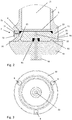
- the extraction cell E shown is clamped in a bracing unit V and has an extraction body 1 for receiving a sample, not shown in detail, which is sealed with a first closure arrangement 2 and a second closure arrangement 3.
- the extraction body 1 is tubular, its lower, first end 10 being closed with the first closure arrangement 2 and its upper, second end 11 being closed with the second closure arrangement.
- the extraction body also has an interior space 12 for receiving the sample.
- the first closure arrangement 2 is shown in FIG Fig. 2 shown enlarged and has a first closure body 20, which in turn provides a circumferential flange 21 which interacts with a first end face 13 of the extraction body 1 and seals it at its lower, first end 10 by means of a first seal 4.
- the first closure body 20 also has a centrally arranged, first fluid connection 22 via which a fluid, for example a solvent, can be supplied or removed.
- a frit 5 is provided between the extraction body 1 and the first closure body 20, which frit can be a porous plate made, for example, of polymers or metal.
- the frit 5 is intended to hold back the mostly powdery sample, while a fluid supplied at the upper end of the extraction body can be discharged through the frit 5 and the first fluid connection 22.
- the porosity of the frit is, for example, 1 to 50 ⁇ m, depending on the application.
- the sample to be examined on the other hand, has a correspondingly larger particle size.
- the second closure arrangement 3 at the upper, second end 11 of the extraction body 1 is constructed identically and accordingly has a second closure body 30 with a second fluid connection 32. Furthermore, the second closure body 30 has a second flange 31 which interacts with a second end face 14 of the extraction body 1 and with a second seal 6.
- the closure bodies in the prior art are usually screwed to the extraction body.
- at least one adhesive arrangement 7 or 8 is provided for holding the first and the second closure arrangement 2, 3 on the extraction body 1.
- the two adhesive arrangements 7, 8 each have first adhesive elements 71 and 81 and second adhesive elements 72 and 82 interacting with them in an adhesive manner, the respective first adhesive element 71 and 81 at the ends of the extraction body 1 and the respective second adhesive element 72 or 82 is attached to the closure assemblies 2 and 3, respectively.
- first and second end faces 13, 14 of the extraction body 1 have first recesses 15 for receiving the first adhesive elements 71 and 81, respectively.
- second recesses 23 and 33 in which the second adhesive elements 72 and 82 are inserted, are provided in the first flange 21 and in the second flange 31.
- the first and second adhesive elements can be held in the associated recesses in particular by means of pressing, shrink fit, screwing or gluing.
- the end Fig. 3 it can be seen that in the illustrated embodiment, three first and second adhesive arrangements 7, 8 are arranged distributed uniformly over the circumference.
- the adhesive arrangements are formed by permanent magnetic adhesive arrangements, so that simply placing the first or second closure body 20, 30 on the associated first or second end face 13, 14 of the extraction body 1 is sufficient to hold it in place.
- the adhesive force must be sufficiently large so that the closure bodies 20, 30, in particular the closure body 20 located at the lower end of the extraction body 1, cannot inadvertently detach due to its own weight and the weight of the sample located in the interior 12. Rather, a sufficiently large, additional force should be required to lift the respective closure body. Taking off the Closure body can in particular take place as an extension of the longitudinal center axis 16 of the extraction body 1, that is to say by means of a linear movement.
- the two closure bodies 20, 30 have a notch 24 on their outer circumferential surface, with which a secure gripping of a robot is ensured.
- the clamping unit V which is part of an extraction system, has an upper clamping jaw 90 and a lower clamping jaw 91, between which the extraction cell E is clamped ( Fig. 1 ). So that a simple centering of the extraction cell can be effected in the bracing unit V, the two closure bodies 20, 30 can each have annular beads 25 which interact with correspondingly complementary bulges 92.
- the first and second closure bodies 20, 30 are pressed onto the extraction body 1, so that a fluid- and pressure-tight closure takes place through the first and second seal 4, 6, which can be used up to 100 bar and enables more.
- the lower clamping jaw 91 is arranged in a stationary manner and only the upper clamping jaw 90 is designed to be movable in the direction of the longitudinal center axis 16.
- the two clamping jaws 90, 91 also have a fluid supply line 93 or a fluid discharge line 94 which can be moved along the longitudinal center axis 16 and which can be connected to the first fluid connection 22 and the second fluid connection 32 in a fluid-tight manner by means of seals 95 and 96, respectively.
- seals 95 and 96 respectively.
- at least part of the fluid can be supplied and discharged via the fluid discharge line 94.
- the extraction process with the extraction system described above is as follows: First, the extraction body 1 is closed at its lower end with the first closure arrangement 2, the first seal 4 and the frit in order to introduce the sample to be examined via the upper end which is still open, the sample usually fills about a third to half of the interior.
- the second closure arrangement 3 with the second seal is then put on and the extraction cell assembled in this way is inserted into the tensioning unit V.
- the upper and lower clamping jaws 90, 91 are brought together with the required pressure relative to one another in order to close the extraction body in a pressure-tight manner. Furthermore, the fluid supply line 93 and the fluid discharge line 94 are connected.
- the provided fluid for example a solvent, optionally under pressure
- the provided fluid is then supplied via the fluid supply line 93 and heated to a predetermined temperature for accelerated extraction by means of a heating device (not shown in detail), whereby a pressure of up to 100 bar can be established.
- a heating device not shown in detail
- pressures above this value can be released via an overpressure valve (not shown in detail).
- a valve opens in connection with the fluid discharge line 94 and the extraction solution is discharged via the fluid discharge line 94.
- the frit 5 inserted at the lower end of the extraction body holds back the sample and only allows the supplied fluid to pass together with the extracted analytes.
- the discharged fluid is then subjected to further processing and / or analysis.
- the extraction cell can also be used in a dynamic method in which the extraction fluid flows continuously through the extraction cell.
- a suitable heating device to heat the extraction body to up to 200 ° C and more.
- the upper clamping jaw is moved apart relative to the lower clamping jaw 91, so that the extraction cell E can be removed manually or by machine using a robot.
- the two locking arrangements 2, 3 can be lifted off in a simple manner, with only the force of attraction of the adhesive arrangements having to be overcome. This can therefore also be done automatically in particular.
- the sample is then emptied into the waste, the frit 5 and the seals 4, 6 possibly being retained for reuse.
- a closure arrangement 200 according to a second exemplary embodiment is shown, which can be used as an alternative to the first or second closure arrangement 2, 3. It is characterized by an outer closure body 201 and an inner closure body 202, the inner closure body 202 being guided displaceably in the outer closure body 201. So that the two closure bodies 201, 202 hold together, on the one hand the outer closure body 201 encompasses the inner closure body 202 and, on the other hand, a spring ring 203 or some other securing means is provided.
- the extraction body 100 has a flange 101 at each of the first and second ends which come into operative contact with the outer closure bodies 201 when the extraction body 100 is closed.
- first adhesive elements 810 are arranged in recesses 102 in the flange 101, which interact with second adhesive elements 820 which are held in recesses 205 of the outer closure body 201.
- Figure 5 shows the closure arrangement 200 in a first closure position (pre-closure position), in which the outer closure body 201 is held by means of the two adhesive elements 810, 820 on the flange 101 of the extraction body. Furthermore, a seal 400 is provided between the extraction body 100 and the inner closure body 202, which, starting from the in FIG Figure 5
- the first closing position shown can be compressed by shifting the inner closing body 202 relative to the outer closing body 201 in order to thereby establish a fluid-tight connection between the interior 120 of the extraction body 100 and the fluid connection 204 provided centrally on the inner closing body 202.
- a frit 500 is held in a recess 103 at one end of the extraction body 100. Between the frit 500 and the extraction body 100 there is an annular gap 121 in the recess 103, which is covered by the seal 400 arranged centrally above the gap 121 so that the seal 400 presses both on the extraction body 100 and on the frit 500 in the compressed state.
- the seal 400 is accommodated in a circumferential groove 206 which is open radially outward and in the direction of the extraction body 100.
- the outer closure body 201 engages around the inner closure body 202, so that the latter can be linearly displaced to a limited extent in the direction of the longitudinal center axis 160, for example by external pressure from the in Figure 1 Bracing device V shown is exercised. So that the inner closure body 202 does not slip out of the outer closure body 201 when the closure arrangement 200 is lifted off the extraction body 100, the inner closure body 202 is secured via the spring ring 203.
- the adjustment path of the inner closure body 202 with respect to the outer closure body 201 is dimensioned such that the seal 400 can be compressed to a sufficient extent in order to produce the desired pressure-tight closure.
- the closure arrangements are the ones shown in FIGS Figures 1 to 5
- the two exemplary embodiments shown are designed in such a way that the adhesive arrangements only serve to hold the closure bodies in the pre-closure position on the extraction body, which ensures filling with a sample and transfer to the bracing unit V.
- the actual pressure-tight closure is only ensured in the bracing unit V in that the two opposing closure bodies are braced relative to one another.
- the interacting adhesive elements are not responsible for the fluid-tight closure, their adhesive force can be made correspondingly lower, so that only a relatively small installation space is required for this.
- the adhesive arrangements have the great advantage that only a linear direction of movement is required to lift and place the closure body, which of course does not rule out a short rotational movement for easier loosening of the closure body.
Abstract
Die erfindungsgemäße Extraktionszelle zur Extraktion einer Probe ist im Wesentlichen durch folgende Merkmale gekennzeichnet: einen rohrförmigen Extraktionskörper mit einem ersten und einem gegenüberliegenden zweiten Ende, der einen Innenraum zur Aufnahme der Probe aufweist, eine erste Verschlussanordnung zum abdichtenden Verschließen des ersten Endes des rohrförmigen Extraktionskörpers, eine zweite Verschlussanordnung zum abdichtenden Verschließen des zweiten Endes des rohrförmigen Extraktionskörpers, wobei die erste Verschlussanordnung einen ersten Fluidanschluss zum Zu- oder Abführen eines Fluids und die zweite Verschlussanordnung einen zweiten Fluidanschluss zum Zu- oder Abführen eines Fluids aufweist. Des Weiteren ist zwischen dem Extraktionskörper und der ersten Verschlussanordnung sowie zwischen dem Extraktionskörper und der zweiten Verschlussanordnung jeweils wenigstens eine Haftanordnung zum Festhalten der ersten und zweiten Verschlussanordnung am Extraktionskörper vorgesehen.The extraction cell according to the invention for extracting a sample is essentially characterized by the following features: a tubular extraction body with a first and an opposite second end which has an interior space for receiving the sample, a first closure arrangement for sealingly closing the first end of the tubular extraction body, a second closure arrangement for sealingly closing the second end of the tubular extraction body, the first closure arrangement having a first fluid connection for supplying or removing a fluid and the second closure arrangement having a second fluid connection for supplying or removing a fluid. Furthermore, between the extraction body and the first closure arrangement and between the extraction body and the second closure arrangement, at least one adhesive arrangement is provided in each case for holding the first and second closure arrangement on the extraction body.
Description
Die Erfindung betrifft eine Extraktionszelle zur Extraktion einer Probe.The invention relates to an extraction cell for extracting a sample.
Mit Hilfe von Extraktionszellen werden üblicherweise unter erhöhter Temperatur und Druck entsprechende Analyten, wie z.B. Pestizide, PCB, PAK, Dioxine und andere Komponenten, aus einem zu untersuchenden Probenmaterial mit Hilfe von Lösungsmitteln extrahiert, die dann meist nach einer weiteren Reinigung einem Analysesystem zugeführt werden.With the help of extraction cells, corresponding analytes, such as pesticides, PCB, PAH, dioxins and other components, are usually extracted from a sample material to be examined with the help of solvents, which are then usually fed to an analysis system after further cleaning.
Extraktionszellen bestehen normalerweise aus einem rohrförmigen Extraktionskörper mit einem ersten und einen gegenüberliegenden zweiten Ende, die über Verschlussanordnungen verschlossen werden, sodass sich ein Innenraum zur Aufnahme einer Probe ergibt. Das Lösungsmittel oder ein anderes geeignetes Fluid wird über die Verschlussanordnungen zu- bzw. abgeführt. Die Extraktionskörper werden üblicherweise mittels Verschlussanordnungen verschlossen, die mit dem Extraktionskörper verschraubt werden, wie dies beispielsweise aus der
Verschraubungen haben jedoch den Nachteil, dass für den Zusammenbau bzw. die Demontage ein mehr oder weniger großer manueller Aufwand erforderlich ist. Weiterhin ist ein automatisiertes Aufsetzen bzw. Entfernen der Verschlussanordnungen aufwendig bzw. schwer umsetzbar. Dementsprechend ist auch eine automatische Entleerung der extrahierten Restprobe samt Filtern schwierig durchführbar. Darüber hinaus erfordern diese bekannten Extraktionszellen oftmals einen erhöhten Reinigungsaufwand aufgrund der Anzahl bzw. Komplexität der Komponenten.However, screw connections have the disadvantage that more or less manual effort is required for assembly or disassembly. Furthermore, an automated attachment or removal of the closure arrangements is complex or difficult to implement. Accordingly, an automatic emptying of the extracted residual sample including filters is difficult to carry out. In addition, these known extraction cells often require an increased cleaning effort due to the number and complexity of the components.
Der Erfindung liegt daher die Aufgabe zugrunde, eine Extraktionszelle zur Extraktion einer Probe anzugeben, die sich durch einen schnellen Zusammenbau bzw. eine schnelle Demontage auszeichnet.The invention is therefore based on the object of specifying an extraction cell for extracting a sample which is characterized by rapid assembly or rapid dismantling.
Erfindungsgemäß wird diese Aufgabe durch die Merkmale des Anspruches 1 gelöst.According to the invention, this object is achieved by the features of
Die erfindungsgemäße Extraktionszelle zur Extraktion einer Probe ist im Wesentlichen durch folgende Merkmale gekennzeichnet:
- einen rohrförmigen Extraktionskörper mit einem ersten und einem gegenüberliegenden zweiten Ende, der einen Innenraum zur Aufnahme der Probe aufweist,
- eine erste Verschlussanordnung zum abdichtenden Verschließen des ersten Endes des rohrförmigen Extraktionskörpers,
- eine zweite Verschlussanordnung zum abdichtenden Verschließen des zweiten Endes des rohrförmigen Extraktionskörpers, wobei
- die erste Verschlussanordnung einen ersten Fluidanschluss zum Zu- oder Abführen eines Fluids und die zweite Verschlussanordnung einen zweiten Fluidanschluss zum Zu- oder Abführen eines Fluids aufweist.
- a tubular extraction body with a first and an opposite second end, which has an interior space for receiving the sample,
- a first closure arrangement for sealingly closing the first end of the tubular extraction body,
- a second closure arrangement for sealingly closing the second end of the tubular extraction body, wherein
- the first closure arrangement has a first fluid connection for supplying or removing a fluid and the second closure arrangement has a second fluid connection for supplying or removing a fluid.
Des Weiteren ist zwischen dem Extraktionskörper und der ersten Verschlussanordnung sowie zwischen dem Extraktionskörper und der zweiten Verschlussanordnung jeweils wenigstens eine Haftanordnung zum Festhalten der ersten und zweiten Verschlussanordnung am Extraktionskörper vorgesehen.Furthermore, between the extraction body and the first closure arrangement and between the extraction body and the second closure arrangement, at least one adhesive arrangement is provided for holding the first and second closure arrangement on the extraction body.
Durch die Haftanordnung ergibt sich der Vorteil, dass die Verschlussanordnung nicht verschraubt, sondern lediglich aufgesetzt bzw. abgezogen werden muss. Dadurch ist beim Aufsetzen bzw. Abnehmen der Verschlussanordnung lediglich eine lineare Bewegung der Verschlussanordnung entlang der Längsmittelachse des Extraktionskörpers erforderlich. Eine solche Bewegung kann auch auf einfache Art und Weise automatisiert durchgeführt werden. Bei einem Gewinde kann der Verschlusskörper nicht mit einer linearen Bewegung abgehoben werden, da das Gewinde diese Bewegungsrichtung blockiert.The adhesive arrangement results in the advantage that the closure arrangement does not have to be screwed on, but only has to be attached or removed. As a result, only a linear movement of the closure arrangement along the longitudinal center axis of the extraction body is required when the closure arrangement is put on or removed. Such a movement can also be carried out in an automated manner in a simple manner. In the case of a thread, the closure body cannot be lifted off with a linear movement because the thread blocks this direction of movement.
Ein weiterer Vorteil der erfindungsgemäßen Haftanordnung gegenüber einer Schraubverbindung besteht auch darin, dass die Haltekraft, mit der die Verschlussanordnung auf dem Extraktionskörper festgehalten wird, gezielt eingestellt werden kann. Durch eine entsprechende Auswahl der Haftanordnung kann die Haltekraft, beispielsweise eines Permanentmagneten, auf die Erfordernisse (Gewicht der Verschlussanordnung, Gewicht der Probe, Anzahl der verwendeten Haftelemente...) abgestimmt werden, um einerseits einen sicheren Halt der Verschlussanordnung auf dem Extraktionskörper zu gewährleisten und andererseits ein Abheben der Verschlussanordnung ohne unnötigen Kraftaufwand durchführen zu können.Another advantage of the adhesive arrangement according to the invention compared to a screw connection is that the holding force with which the closure arrangement is held on the extraction body can be adjusted in a targeted manner. By selecting the detention order accordingly, you can the holding force, for example of a permanent magnet, can be matched to the requirements (weight of the closure arrangement, weight of the sample, number of adhesive elements used ...), on the one hand to ensure a secure hold of the closure arrangement on the extraction body and on the other hand to lift the closure arrangement without unnecessary To be able to perform effort.
Die bevorzugte Ausführungsform der Erfindung besteht darin, dass die wenigstens eine Haftanordnung als permanentmagnetische Haftanordnung ausgebildet ist. Hierbei können Permanentmagneten, insbesondere Neodym- Samarium-Cobald- oder Ferritmagneten zur Anwendung kommen. Prinzipiell wäre es aber im Rahmen der Erfindung auch denkbar, dass anstelle der permanentmagnetischen Haftanordnung Klettverschlüsse oder ein auf silikonbasierender Verschluss zur Anwendung kommen. Die Haftanordnung kann ein oder mehrere Haftelemente aufweisen, die ringförmig ausgebildet sind. Bevorzugt wird aber eine Ausführungsform, bei der an den Enden des Extraktionskörpers jeweils mehrere über den Umfang verteilt angeordnete erste Haftelemente vorgesehen sind, die mit einer entsprechenden Anzahl an zweiten Haftelementen an den beiden Verschlussanordnungen zusammenwirken. Die Haftanordnung ist so auszubilden, dass sie für den vorgesehenen Temperaturbereich von beispielsweise 200°C geeignet ist. Die Haftanordnungen ermöglichen eine schnelle Montage bzw. Demontage der Extraktionszelle. Außerdem ist auch eine automatisierte Handhabung leicht umsetzbar.The preferred embodiment of the invention consists in that the at least one adhesive arrangement is designed as a permanent magnetic adhesive arrangement. Permanent magnets, in particular neodymium, samarium, cobalt or ferrite magnets can be used here. In principle, however, it would also be conceivable within the scope of the invention for Velcro fasteners or a silicone-based fastener to be used instead of the permanent magnetic adhesive arrangement. The adhesive arrangement can have one or more adhesive elements which are designed in the form of a ring. However, an embodiment is preferred in which at the ends of the extraction body a plurality of first adhesive elements distributed over the circumference are provided, which interact with a corresponding number of second adhesive elements on the two closure arrangements. The adhesive arrangement must be designed in such a way that it is suitable for the intended temperature range of, for example, 200 ° C. The detention arrangements enable quick assembly and disassembly of the extraction cell. In addition, automated handling can also be easily implemented.
Gemäß einer weiteren Ausgestaltung der Erfindung weist die erste und zweite Verschlussanordnung jeweils einen äußeren und einen inneren Verschlusskörper auf, wobei der innere Verschlusskörper am äußeren Verschlusskörper verschiebbar geführt ist. Weiterhin ist zwischen dem Extraktionskörper und dem inneren Verschlusskörper vorzugsweise eine Dichtung vorgesehen, die durch Verschiebung des inneren Verschlusskörpers relativ zum äußeren Verschlusskörper zum Zwecke einer fluiddichten Verbindung komprimierbar ist. Dadurch ist es möglich, dass die Verschlussanordnungen eine erste Verschlussstellung (Vorverschlussstellung) aufweisen, in welcher der äußere Verschlusskörper über die wenigstens eine Haftanordnung am Extraktionskörper festgestellten wird und sich der innere Verschlusskörper relativ zum äußeren Verschlusskörper in einer die Dichtung noch nicht komprimierenden Stellung befindet. Weiterhin sehen die Verschlussanordnungen eine zweite Verschlussstellung (fluiddichte Verschlussstellung) vor, in welcher der äußere Verschlusskörper nach wie vor über die Haftanordnungen am Extraktionskörper festgehalten wird und sich der innere Verschlusskörper relativ zum äußeren Verschlusskörper in einer die Dichtung komprimierenden Stellung befindet.According to a further embodiment of the invention, the first and second closure arrangements each have an outer and an inner closure body, the inner closure body being displaceably guided on the outer closure body. Furthermore, a seal is preferably provided between the extraction body and the inner closure body, which seal can be compressed by shifting the inner closure body relative to the outer closure body for the purpose of a fluid-tight connection. This makes it possible for the locking arrangements to have a first locking position (pre-locking position) have, in which the outer closure body is fixed on the extraction body via the at least one adhesive arrangement and the inner closure body is in a position not yet compressing the seal relative to the outer closure body. Furthermore, the closure arrangements provide a second closure position (fluid-tight closure position) in which the outer closure body is still held on the extraction body via the adhesive arrangements and the inner closure body is in a position compressing the seal relative to the outer closure body.
Der klassische Einsatzbereich der erfindungsgemäßen Extraktionszelle liegt bei Temperaturen bis 200°C und Drücken von 0 bis 100 bar. Ein fluiddichter Verschluss des Extraktionskörpers ist bei hohen Drücken von bis zu 100 bar natürlich nicht durch die Haftanordnung praktikabel realisierbar. Die Verschlussanordnungen sehen daher die oben beschriebene eine erste und eine zweite Verschlussstellung vor, wobei in der ersten Verschlussstellung die Verschlussanordnung lediglich am Extraktionskörper festgehalten wird, um den auf diese Weise verschlossenen Extraktionskörper insbesondere in eine Einspannvorrichtung zu transferieren, in der die beiden inneren Verschlusskörper derart eingespannt werden, dass sie sich relativ zu ihren äußeren Verschlusskörpern in Richtung der Extraktionszelle bewegen und dabei die dazwischen angeordneten Dichtungen komprimieren, um auf diese Weise die fluiddichte zweite Verschlussstellung herstellen.The classic area of application of the extraction cell according to the invention is at temperatures up to 200 ° C. and pressures from 0 to 100 bar. A fluid-tight closure of the extraction body is of course not practicable at high pressures of up to 100 bar due to the adhesive arrangement. The closure arrangements therefore provide the above-described first and second closure positions, with the closure arrangement only being held on the extraction body in the first closure position in order to transfer the extraction body closed in this way, in particular, into a clamping device in which the two inner closure bodies are clamped in this way be that they move relative to their outer closure bodies in the direction of the extraction cell and thereby compress the seals arranged between them, in order in this way to produce the fluid-tight second closure position.
Die Zugabe eines Extraktionsfluids, üblicherweise ein Lösemittel, kann dann unter erhöhtem Druck erfolgen. Darüber hinaus kann sich der Druck des Extraktionsfluids durch die zur beschleunigtenAn extraction fluid, usually a solvent, can then be added under increased pressure. In addition, the pressure of the extraction fluid can be accelerated by the
Sobald die Extraktionszelle aus der Verspanneinheit wieder herausgenommen wird, kann sie auf schnelle und einfache Art und Weise durch Abheben der Verschlussanordnungen geöffnet werden. Der Zusammenbau und das Öffnen der Extraktionszellen werden daher durch die erfindungsgemäße Haftanordnung wesentlich vereinfacht und können darüber hinaus leicht automatisiert werden. Weiterhin besteht die Möglichkeit, das nach Abnahme der Verschlussanordnungen, beispielsweise durch einen Roboter, die Extraktionszelle automatisch in den Abfall entleert wird, wobei die Dichtungen und etwaige Fritten als Einweg-Komponenten ausgebildet sein können, was aber nicht zwingend erforderlich ist. Die Dichtung besteht vorzugsweise aus einem geeigneten Polymer, während die Fritte aus Polymeren bzw. Biopolymeren oder Metall bestehen kann.As soon as the extraction cell is removed from the clamping unit again, it can be opened in a quick and simple manner by lifting off the locking arrangement. The assembly and opening of the extraction cells are therefore considerably simplified by the adhesive arrangement according to the invention and, moreover, can easily be automated. Furthermore, there is the possibility, after removing the locking arrangements, for example by a robot, the extraction cell is automatically emptied into the waste, whereby the seals and any frits can be designed as single-use components, but this is not absolutely necessary. The seal preferably consists of a suitable polymer, while the frit can consist of polymers or biopolymers or metal.
Die Haftanordnung weist wenigstens ein erstes Haftelement und wenigstens ein mit diesem haftend zusammenwirkendes zweites Haftelement auf, wobei das wenigstens eine erste Haftelement an den Enden des Extraktionskörpers und das wenigstens eine zweite Haftelement an den Verschlussanordnungen befestigt ist. Dabei kann die Extraktionszelle am ersten und zweiten Ende jeweils einen Flansch aufweisen, die in der ersten und zweiten Verschlussstellung mit dem äußeren Verschlusskörper der zugehörigen Verschlussanordnung in festhaltendem Wirkkontakt stehen. Die erste und zweite Haftanordnung können jeweils wenigstens ein erstes Haftelement und wenigstens ein mit diesem haftend zusammenwirkendes zweites Haftelement aufweisen, wobei das wenigstens eine erste Haftelement am Flansch des Extraktionskörpers und das wenigstens eine zweite Haftelement am äußeren Verschlusskörpers befestigt ist. In einer weiteren Ausgestaltung können die ersten Haftelemente in Ausnehmungen im Flansch des Extraktionskörpers und die zweiten Haftelemente in Ausnehmungen der äußeren Verschlusskörper vorgesehen werden.The adhesive arrangement has at least one first adhesive element and at least one second adhesive element which interacts adhesively with the latter, the at least one first adhesive element being attached to the ends of the extraction body and the at least one second adhesive element being attached to the closure arrangements. In this case, the extraction cell can each have a flange at the first and second end which, in the first and second closed position, are in holding operative contact with the outer closure body of the associated closure arrangement. The first and second adhesive arrangements can each have at least one first adhesive element and at least one second adhesive element that interacts adhesively with this, wherein the at least one first adhesive element is attached to the flange of the extraction body and the at least one second adhesive element is attached to the outer closure body. In a further embodiment, the first adhesive elements can be provided in recesses in the flange of the extraction body and the second adhesive elements can be provided in recesses in the outer closure body.
Die Befestigung der ersten und zweiten Haftelemente in den zugehörigen Ausnehmungen kann beispielsweise durch Pressung, Schrumpfsitz, Verschraubung oder Klebung erfolgen. Um eine möglichst zuverlässige Halterung der Verschlussanordnungen an den Extraktionskörper zu gewährleisten, sind an den Enden des Extraktionskörpers jeweils mehrere über den Umfang verteilt angeordnete erste Haftelemente vorgesehen, die mit einer entsprechenden Anzahl an zweiten Haftelementen an den beiden Verschlussanordnungen zusammenwirken.The first and second adhesive elements can be fastened in the associated recesses, for example, by pressing, shrink fit, screwing or gluing. To ensure that the closure arrangements are held on the extraction body as reliably as possible, a plurality of first adhesive elements distributed over the circumference are provided at the ends of the extraction body and interact with a corresponding number of second adhesive elements on the two closure arrangements.
Außerdem sind der erste Fluidanschluss am inneren Verschlusskörper der ersten Verschlussanordnung und der zweite Fluidanschluss am inneren Verschlusskörper der zweiten Verschlussanordnung angeordnet, sodass durch Verschiebung des inneren Verschlusskörpers und die dadurch bedingte Komprimierung der Dichtung der fluiddichte Verschluss zwischen dem Innenraum des Extraktionskörpers und den beiden Fluidanschlüssen gewährleistet ist.In addition, the first fluid connection is arranged on the inner closure body of the first closure arrangement and the second fluid connection is arranged on the inner closure body of the second closure arrangement, so that the displacement of the inner closure body and the resulting compression of the seal the fluid-tight seal between the interior of the extraction body and the two fluid connections is ensured.
Durch die Verwendung einer Haftanordnung zur Halterung der Verschlusskörper am Extraktionskörper besteht die Möglichkeit, die Verschlussanordnung in Richtung der Längsmittelachse des Extraktionskörpers zwischen einer abgehobenen Öffnungsstellung und einer ersten Verschlussstellung (Vorverschlussstellung) linear zu bewegen, wobei die Verschlussanordnung in der ersten Verschlussstellung mittels der Haftanordnung am Extraktionskörper festgehalten wird. Auf diese Weise ist eine relativ einfache automatisierte Öffnung bzw. Verschließung des Extraktionskörpers durchführbar.By using an adhesive arrangement to hold the closure body on the extraction body, it is possible to move the closure arrangement linearly in the direction of the longitudinal center axis of the extraction body between a raised open position and a first closure position (pre-closure position), the closure arrangement in the first closure position by means of the adhesive arrangement on the extraction body is being held. In this way, a relatively simple automated opening or closing of the extraction body can be carried out.
In vielen Anwendungsfällen wird als Filter eine Fritte vorgesehen, die vorzugsweise zwischen der wenigstens einen ersten Verschlussanordnung und dem Extraktionskörper gehaltert ist. Hierzu kann die Fritte insbesondere in einer Aussparung des Extraktionskörpers gehalten werden. Besonders vorteilhaft kann dann die Dichtung zwischen dem inneren Verschlusskörper und der Fritte vorgesehen werden. In einer praktischen Ausführung verbleibt durch das Einsetzen der Fritte in die Aussparung des Extraktionskörpers ein ringförmiger Spalt, wobei die vom inneren Verschlusskörper komprimierte Dichtung zweckmäßigerweise im Bereich des Spalts sowohl auf den Extraktionskörper als auch auf die Fritte drückt. Die Dichtung ist somit etwa mittig über den Spalt angeordnet und stellt damit zum einen nach außen den fluiddichten Verschluss her und sichert gleichzeitig die Fritte in der Aussparung des Extraktionskörpers.In many applications, a frit is provided as the filter, which is preferably held between the at least one first closure arrangement and the extraction body. For this purpose, the frit can in particular be held in a recess in the extraction body. The seal between the inner closure body and the frit can then be provided particularly advantageously. In a practical embodiment, the insertion of the frit into the recess of the extraction body leaves an annular gap, the seal compressed by the inner closure body expediently pressing both on the extraction body and on the frit in the area of the gap. The seal is thus arranged approximately centrally over the gap and thus on the one hand produces the fluid-tight seal towards the outside and at the same time secures the frit in the recess of the extraction body.
Weitere Ausgestaltungen der Erfindung werden anhand der nachfolgenden Beschreibung zweier Ausführungsbeispiele und der Zeichnung näher erläutert.Further refinements of the invention are explained in greater detail on the basis of the following description of two exemplary embodiments and the drawing.
In der Zeichnung zeigen
- Fig. 1
- eine Schnittdarstellung einer erfindungsgemäßen Extraktionszelle im eingespannten Zustand,
- Fig. 2
- eine vergrößerte Schnittdarstellung des Details A der
Fig. 1 , - Fig. 3
- eine Draufsicht der Extraktionszelle gemäß
Fig. 1 , - Fig. 4
- eine dreidimensionale Darstellung einer Verschlussanordnung gemäß einem zweiten Ausführungsbeispiel und
- Fig. 5
- eine Schnittdarstellung der Verschlussanordnung gemäß
Fig. 4 .
- Fig. 1
- a sectional view of an extraction cell according to the invention in the clamped state,
- Fig. 2
- an enlarged sectional view of the detail A of FIG
Fig. 1 , - Fig. 3
- a top view of the extraction cell according to FIG
Fig. 1 , - Fig. 4
- a three-dimensional representation of a closure arrangement according to a second embodiment and
- Fig. 5
- a sectional view of the closure arrangement according to
Fig. 4 .
Die in
Die erste Verschlussanordnung 2 ist in
Damit die beiden Verschlusskörper 20, 30 beim Einsetzen der Extraktionszelle E in die Verspanneinheit V nicht versehentlich abfallen, werden die Verschlusskörper im Stand der Technik üblicherweise mit dem Extraktionskörper verschraubt. Beim erfindungsgemäßen Ausführungsbeispiel sind jedoch zwischen dem Extraktionskörper 1 und der ersten Verschlussanordnung 2 sowie zwischen dem Extraktionskörper 1 und der zweiten Verschlussanordnung 3 jeweils wenigstens eine Haftanordnung 7 bzw. 8 zum Festhalten der ersten und der zweiten Verschlussanordnung 2, 3 am Extraktionskörper 1 vorgesehen. Die beiden Haftanordnungen 7, 8 weisen dabei jeweils erste Haftelemente 71 bzw. 81 und mit diesen haftend zusammenwirkende zweite Haftelemente 72 bzw. 82 auf, wobei das jeweils erste Haftelement 71 bzw. 81 an den Enden des Extraktionskörpers 1 und das jeweils zweite Haftelement 72 bzw. 82 an den Verschlussanordnungen 2 bzw. 3 befestigt ist. Dazu weisen die erste und zweite Stirnfläche 13, 14 des Extraktionskörpers 1 erste Ausnehmungen 15 zur Aufnahme der ersten Haftelemente 71 bzw. 81 auf. In entsprechender Weise sind im ersten Flansch 21 und im zweiten Flansch 31 zweite Ausnehmungen 23 bzw. 33 vorgesehen, in denen die zweiten Haftelemente 72 bzw. 82 eingesetzt sind. Die ersten und zweiten Haftelemente können dabei insbesondere mittels Pressung, Schrumpfsitz, Verschraubung oder Klebung in den zugehörigen Ausnehmungen gehaltert werden. Aus
Gemäß einer bevorzugten Ausgestaltung der Erfindung werden die Haftanordnungen durch permanentmagnetische Haftanordnungen ausgebildet, sodass lediglich ein Aufsetzen des ersten bzw. zweiten Verschlusskörpers 20, 30 auf die zugehörige erste bzw. zweite Stirnfläche 13, 14 des Extraktionskörper 1 ausreicht, um diese festzuhalten. Die Haftkraft ist dabei ausreichend groß zu bemessen, sodass sich die Verschlusskörper 20, 30, insbesondere der sich am unteren Ende des Extraktionskörpers 1 befindliche Verschlusskörper 20, nicht durch sein Eigengewicht und dem Gewicht der im Innenraum 12 befindlichen Probe unabsichtlich lösen können. Es sollte vielmehr eine ausreichend große, zusätzliche Kraft erforderlich sein, um den jeweiligen Verschlusskörper abzuheben. Das Abheben der Verschlusskörper kann dabei insbesondere in Verlängerung der Längsmittelachse 16 des Extraktionskörpers 1, also durch eine lineare Bewegung erfolgen.According to a preferred embodiment of the invention, the adhesive arrangements are formed by permanent magnetic adhesive arrangements, so that simply placing the first or
Um ein automatisiertes Abnehmen des ersten bzw. zweiten Verschlusskörpers 20, 30 zu ermöglichen, ist es von Vorteil, wenn die beiden Verschlusskörper 20, 30 auf ihrer äußeren Umfangsfläche eine Einkerbung 24 aufweisen, mit der ein sicheres Greifen eines Roboters gewährleistet ist.In order to enable an automated removal of the first or
Die Verspanneinheit V, die Teil eines Extraktionssystems ist, weist einen oberen Spannbacken 90 und einen unteren Spannbacken 91 auf, zwischen denen die Extraktionszelle E eingespannt wird (
Durch eine entsprechende Druckbeaufschlagung der Spannbacken 90 bzw. 91 werden der erste und zweite Verschlusskörper 20, 30 auf den Extraktionskörper 1 gedrückt, sodass durch die erste und zweite Dichtung 4, 6 ein fluid- und druckdichter Verschluss erfolgt, der Anwendungen bis zu 100 bar und mehr ermöglicht. Dabei kann vorgesehen werden, dass der untere Spannbacken 91 ortsfest angeordnet ist und lediglich der obere Spannbacken 90 in Richtung der Längsmittelachse 16 verfahrbar ausgebildet ist. Die beiden Spannbacken 90, 91 weisen darüber hinaus eine längs der Längsmittelachse 16 verfahrbare Fluidzuführleitung 93 bzw. eine Fluidabführleitung 94 auf, die mittels Dichtungen 95 bzw. 96 fluiddicht am ersten Fluidanschluss 22 bzw. am zweiten Fluidanschluss 32 angeschlossen werden können. Es ist dabei in bestimmten Anwendungsfällen auch denkbar, dass zumindest ein Teil des Fluids über die Fluidabführleitung 94 zugeführt und abgeführt werden kann.By applying pressure to the clamping
Das Extraktionsverfahren mit dem oben beschriebenen Extraktionssystem läuft wie folgt ab:
Zunächst wird der Extraktionskörper 1 an seinem unteren Ende mit der ersten Verschlussanordnung 2, der erste Dichtung 4 und der Fritte verschlossen, um die zu untersuchende Probe über das noch offene obere Ende einzubringen, wobei die Probe üblicherweise etwa ein Drittel bis zur Hälfte des Innenraums ausfüllt. Sodann wird die zweite Verschlussanordnung 3 mit der zweiten Dichtung aufgesetzt und die so zusammengebaute Extraktionszelle in die Verspanneinheit V eingesetzt. Die obere und untere Spannbacke 90, 91 werden mit dem erforderlichen Druck relativ zueinander zusammengeführt, um den Extraktionskörper druckdicht zu verschließen. Weiterhin werden die Fluidzuführleitung 93 und Fluidabführleitung 94 angeschlossen. Sodann wird über die Fluidzuführleitung 93 das vorgesehene Fluid, beispielsweise ein Lösungsmittel gegebenenfalls unter Druck zugeführt und zur beschleunigten Extraktion auf eine vorgegebene Temperatur mittels einer nicht näher dargestellten Heizeinrichtung erwärmt, wobei sich ein Druck von bis zu 100 bar einstellen kann. Drücke über diesem Wert können aus Sicherheitsgründen über ein nicht näher dargestelltes Überdruckventil abgelassen. Nach der Extraktion und nach Unterschreiten eines kritischen Sicherheitsdruckes öffnet im Anschluss an die Fluidabführleitung 94 ein Ventil und die Extraktionslösung wird über die Fluidabführleitung 94 abgeführt. Die am unteren Ende des Extraktionskörpers eingesetzte Fritte 5 hält dabei die Probe zurück und lässt lediglich das zugeführte Fluid zusammen mit den extrahierten Analyten passieren. Das abgeführte Fluid wird dann einer weiteren Bearbeitung und/oder Analyse unterzogen.The extraction process with the extraction system described above is as follows:
First, the
Anstelle des oben beschriebenen statischen Verfahrens kann die Extraktionszelle aber auch bei einem dynamischen Verfahren eingesetzt werden, bei dem das Extraktionsfluid die Extraktionszelle kontinuierlich durchströmt.Instead of the static method described above, the extraction cell can also be used in a dynamic method in which the extraction fluid flows continuously through the extraction cell.
Je nach Anwendung besteht auch die Möglichkeit, den Extraktionskörper über eine geeignete Heizeinrichtung auf bis zu 200°C und mehr aufzuheizen.Depending on the application, it is also possible to use a suitable heating device to heat the extraction body to up to 200 ° C and more.
Zum Entfernen und Entleeren der Extraktionszelle E wird der obere Spannbacken relativ zum unteren Spannbacken 91 auseinander gefahren, sodass die Extraktionszelle E manuell oder maschinell mittels eines Roboters entnommen werden kann. Die beiden Verschlussanordnungen 2, 3 können auf einfache Weise abgehoben werden, wobei lediglich die Anziehungskraft der Haftanordnungen zu überwinden ist. Dies kann daher insbesondere auch automatisiert erfolgen. Die Probe wird dann in den Abfall entleert, wobei die Fritte 5 und die Dichtungen 4, 6 ggf. zur Wiederverwendung zurückbehalten werden.To remove and empty the extraction cell E, the upper clamping jaw is moved apart relative to the
In den
Der Extraktionskörper 100 weist am ersten und zweiten Ende jeweils einen Flansch 101 auf, die beim Verschließen des Extraktionskörpers 100 mit den äußeren Verschlusskörpern 201 in Wirkkontakt kommen. Hierzu sind in Ausnehmungen 102 im Flansch 101 erste Haftelemente 810 angeordnet, die mit zweiten Haftelementen 820 zusammenwirken, die in Ausnehmungen 205 des äußeren Verschlusskörpers 201 gehaltert sind.The
Im dargestellten Ausführungsbeispiel ist in einer Aussparung 103 an einem Ende des Extraktionskörpers 100 eine Fritte 500 gehaltert. Zwischen der Fritte 500 und dem Extraktionskörpers 100 ergibt sich in der Aussparung 103 ein ringförmiger Spalt 121, der von der mittig über dem Spalt 121 angeordneten Dichtung 400 abdeckt wird, sodass die Dichtung 400 im komprimierten Zustand sowohl auf den Extraktionskörper 100 als auch auf die Fritte 500 drückt. Die Dichtung 400 ist in einer radial nach außen und in Richtung des Extraktionskörpers 100 offenen Umfangsnut 206 untergebracht. Der äußere Verschlusskörper 201 umgreift den inneren Verschlusskörper 202, sodass letzterer begrenzt in Richtung der Längsmittelachse 160 linear verschiebbar ist, indem beispielsweise äußere Druck durch die in
Da ein druckdichter Verschluss des Extraktionskörpers für Anwendungen von Drücken bis zu 100 bar nicht alleine durch die Haftanordnungen bewirkt werden kann, sind die Verschlussanordnungen der in den
Da die zusammenwirkenden Haftelemente nicht für den fluiddichten Verschluss verantwortlich sind, können diese in ihrer Haftkraft entsprechend geringer ausgebildet werden, sodass hierfür nur ein relativ kleiner Bauraum erforderlich ist. Gegenüber den bisher verwendeten Gewindeverschraubungen haben die Haftanordnungen aber den großen Vorteil, dass zum Abheben und Aufsetzen der Verschlusskörper lediglich eine lineare Bewegungsrichtung erforderlich ist, was aber natürlich nicht ausschließt, das zum leichteren Lösen der Verschlusskörper eine kurze Rotationsbewegung erfolgt.Since the interacting adhesive elements are not responsible for the fluid-tight closure, their adhesive force can be made correspondingly lower, so that only a relatively small installation space is required for this. Compared to the previously used threaded screw connections, the adhesive arrangements have the great advantage that only a linear direction of movement is required to lift and place the closure body, which of course does not rule out a short rotational movement for easier loosening of the closure body.
Claims (15)
zwischen dem Extraktionskörper (1, 100) und der ersten Verschlussanordnung (2, 200) sowie zwischen dem Extraktionskörper (1, 100) und der zweiten Verschlussanordnung (2, 200) jeweils wenigstens eine Haftanordnung (7, 8) zum Festhalten der ersten und zweiten Verschlussanordnung (2, 3, 200) am Extraktionskörper (1, 100) vorgesehen ist.Extraction cell (E) for extracting a sample with
between the extraction body (1, 100) and the first closure arrangement (2, 200) and between the extraction body (1, 100) and the second closure arrangement (2, 200) each at least one adhesive arrangement (7, 8) for holding the first and second Closure arrangement (2, 3, 200) is provided on the extraction body (1, 100).
Priority Applications (3)
| Application Number | Priority Date | Filing Date | Title |
|---|---|---|---|
| EP20172899.5A EP3907005B1 (en) | 2020-05-05 | 2020-05-05 | Extraction cell for extracting a sample |
| US17/213,595 US20210346884A1 (en) | 2020-05-05 | 2021-03-26 | Extraction cell for extracting a sample |
| CN202120733715.3U CN215218242U (en) | 2020-05-05 | 2021-04-12 | Extraction cell for extracting samples |
Applications Claiming Priority (1)
| Application Number | Priority Date | Filing Date | Title |
|---|---|---|---|
| EP20172899.5A EP3907005B1 (en) | 2020-05-05 | 2020-05-05 | Extraction cell for extracting a sample |
Publications (2)
| Publication Number | Publication Date |
|---|---|
| EP3907005A1 true EP3907005A1 (en) | 2021-11-10 |
| EP3907005B1 EP3907005B1 (en) | 2022-01-19 |
Family
ID=70553846
Family Applications (1)
| Application Number | Title | Priority Date | Filing Date |
|---|---|---|---|
| EP20172899.5A Active EP3907005B1 (en) | 2020-05-05 | 2020-05-05 | Extraction cell for extracting a sample |
Country Status (3)
| Country | Link |
|---|---|
| US (1) | US20210346884A1 (en) |
| EP (1) | EP3907005B1 (en) |
| CN (1) | CN215218242U (en) |
Cited By (1)
| Publication number | Priority date | Publication date | Assignee | Title |
|---|---|---|---|---|
| DE102020134836B3 (en) | 2020-12-23 | 2022-03-24 | LCTech GmbH | Extraction system for extracting analytes from a sample |
Citations (3)
| Publication number | Priority date | Publication date | Assignee | Title |
|---|---|---|---|---|
| WO1996027418A1 (en) | 1995-03-03 | 1996-09-12 | Dionex Corporation | High pressure and temperature solvent extraction cell |
| US7101477B1 (en) * | 2005-09-13 | 2006-09-05 | Agilent Technologies, Inc. | Liquid chromatography column having metal to metal seals |
| EP2918323A1 (en) | 2014-03-12 | 2015-09-16 | Dionex Corporation | Extraction cell assembly with quick-release seal removal |
Family Cites Families (4)
| Publication number | Priority date | Publication date | Assignee | Title |
|---|---|---|---|---|
| US4045291A (en) * | 1976-07-15 | 1977-08-30 | Berger Jacob E | Tissue specimen container |
| JP6427007B2 (en) * | 2012-01-30 | 2018-11-21 | レプリゲン・コーポレイションRepligen Corporation | Chromatography column |
| WO2016197123A2 (en) * | 2015-06-05 | 2016-12-08 | Douglas Scientific, LLC | Sample processing devices, and methods of use thereof |
| US10656118B2 (en) * | 2017-02-02 | 2020-05-19 | Ika-Werke Gmbh & Co. Kg | Closure for an electrochemical vessel, electrochemical vessel and laboratory device |
-
2020
- 2020-05-05 EP EP20172899.5A patent/EP3907005B1/en active Active
-
2021
- 2021-03-26 US US17/213,595 patent/US20210346884A1/en active Pending
- 2021-04-12 CN CN202120733715.3U patent/CN215218242U/en active Active
Patent Citations (3)
| Publication number | Priority date | Publication date | Assignee | Title |
|---|---|---|---|---|
| WO1996027418A1 (en) | 1995-03-03 | 1996-09-12 | Dionex Corporation | High pressure and temperature solvent extraction cell |
| US7101477B1 (en) * | 2005-09-13 | 2006-09-05 | Agilent Technologies, Inc. | Liquid chromatography column having metal to metal seals |
| EP2918323A1 (en) | 2014-03-12 | 2015-09-16 | Dionex Corporation | Extraction cell assembly with quick-release seal removal |
Cited By (2)
| Publication number | Priority date | Publication date | Assignee | Title |
|---|---|---|---|---|
| DE102020134836B3 (en) | 2020-12-23 | 2022-03-24 | LCTech GmbH | Extraction system for extracting analytes from a sample |
| US11927513B2 (en) | 2020-12-23 | 2024-03-12 | LCTech GmbH | Extraction system for extracting analytes from a sample |
Also Published As
| Publication number | Publication date |
|---|---|
| EP3907005B1 (en) | 2022-01-19 |
| US20210346884A1 (en) | 2021-11-11 |
| CN215218242U (en) | 2021-12-17 |
Similar Documents
| Publication | Publication Date | Title |
|---|---|---|
| EP0671984B1 (en) | Press tool | |
| DE4021836C1 (en) | ||
| EP0023005A1 (en) | Tool for the production of a tube-connection | |
| DE102012213089A1 (en) | Coupling formation of a pipetting channel of a pipetting device for coupling a pipette tip thereto | |
| CH702687B1 (en) | Pressing device. | |
| EP2952790A1 (en) | Intermediate piece for a valve | |
| WO1986005425A1 (en) | Fast clamping device | |
| EP3907005B1 (en) | Extraction cell for extracting a sample | |
| EP2843279A2 (en) | Closure element for a blocking device, and blocking device | |
| EP2873512B1 (en) | Device for stamping and welding plastic parts | |
| DE4138974C2 (en) | ||
| EP0169471A2 (en) | Tool for extracting a tube from a tube sheet | |
| EP1506833A1 (en) | Laser nozzle coupling | |
| EP0215294A2 (en) | Apparatus for the hydraulic expansion of tubes | |
| DE4110437A1 (en) | MECHANICAL CENTRAL PART OF A TIRE VOLCANIZER | |
| WO2014044339A1 (en) | Rheological measurement device with a coupling between a drive shaft and a measuring-part shaft | |
| EP3606858B1 (en) | Coupling device, lifting assembly and adjusting method for a coupling device | |
| DE2050332C2 (en) | Combined glove changing and locking device | |
| EP3220002A1 (en) | Flanging device | |
| EP0643228A1 (en) | Device for clamping an axially movable rod | |
| DE3640111C2 (en) | ||
| DE3400638A1 (en) | Pipe connection | |
| DE202009008413U1 (en) | Tool system for a forming press | |
| EP1660239B1 (en) | Apparatus for filling storage containers on dispensing devices | |
| EP3021017A1 (en) | Safety valve |
Legal Events
| Date | Code | Title | Description |
|---|---|---|---|
| STAA | Information on the status of an ep patent application or granted ep patent |
Free format text: STATUS: EXAMINATION IS IN PROGRESS |
|
| PUAI | Public reference made under article 153(3) epc to a published international application that has entered the european phase |
Free format text: ORIGINAL CODE: 0009012 |
|
| REG | Reference to a national code |
Ref country code: DE Ref legal event code: R079 Ref document number: 502020000567 Country of ref document: DE Free format text: PREVIOUS MAIN CLASS: B01L0003000000 Ipc: B01D0011020000 |
|
| 17P | Request for examination filed |
Effective date: 20201007 |
|
| AK | Designated contracting states |
Kind code of ref document: A1 Designated state(s): AL AT BE BG CH CY CZ DE DK EE ES FI FR GB GR HR HU IE IS IT LI LT LU LV MC MK MT NL NO PL PT RO RS SE SI SK SM TR |
|
| B565 | Issuance of search results under rule 164(2) epc |
Effective date: 20200925 |
|
| GRAP | Despatch of communication of intention to grant a patent |
Free format text: ORIGINAL CODE: EPIDOSNIGR1 |
|
| STAA | Information on the status of an ep patent application or granted ep patent |
Free format text: STATUS: GRANT OF PATENT IS INTENDED |
|
| GRAS | Grant fee paid |
Free format text: ORIGINAL CODE: EPIDOSNIGR3 |
|
| RIC1 | Information provided on ipc code assigned before grant |
Ipc: B01L 3/00 20060101ALI20211108BHEP Ipc: G01N 1/40 20060101ALI20211108BHEP Ipc: B01J 3/03 20060101ALI20211108BHEP Ipc: B01D 11/02 20060101AFI20211108BHEP |
|
| GRAA | (expected) grant |
Free format text: ORIGINAL CODE: 0009210 |
|
| STAA | Information on the status of an ep patent application or granted ep patent |
Free format text: STATUS: THE PATENT HAS BEEN GRANTED |
|
| INTG | Intention to grant announced |
Effective date: 20211124 |
|
| AK | Designated contracting states |
Kind code of ref document: B1 Designated state(s): AL AT BE BG CH CY CZ DE DK EE ES FI FR GB GR HR HU IE IS IT LI LT LU LV MC MK MT NL NO PL PT RO RS SE SI SK SM TR |
|
| REG | Reference to a national code |
Ref country code: GB Ref legal event code: FG4D Free format text: NOT ENGLISH |
|
| REG | Reference to a national code |
Ref country code: CH Ref legal event code: EP |
|
| REG | Reference to a national code |
Ref country code: DE Ref legal event code: R096 Ref document number: 502020000567 Country of ref document: DE |
|
| REG | Reference to a national code |
Ref country code: AT Ref legal event code: REF Ref document number: 1463454 Country of ref document: AT Kind code of ref document: T Effective date: 20220215 |
|
| REG | Reference to a national code |
Ref country code: IE Ref legal event code: FG4D Free format text: LANGUAGE OF EP DOCUMENT: GERMAN |
|
| REG | Reference to a national code |
Ref country code: NL Ref legal event code: FP |
|
| REG | Reference to a national code |
Ref country code: LT Ref legal event code: MG9D |
|
| PG25 | Lapsed in a contracting state [announced via postgrant information from national office to epo] |
Ref country code: SE Free format text: LAPSE BECAUSE OF FAILURE TO SUBMIT A TRANSLATION OF THE DESCRIPTION OR TO PAY THE FEE WITHIN THE PRESCRIBED TIME-LIMIT Effective date: 20220119 Ref country code: RS Free format text: LAPSE BECAUSE OF FAILURE TO SUBMIT A TRANSLATION OF THE DESCRIPTION OR TO PAY THE FEE WITHIN THE PRESCRIBED TIME-LIMIT Effective date: 20220119 Ref country code: PT Free format text: LAPSE BECAUSE OF FAILURE TO SUBMIT A TRANSLATION OF THE DESCRIPTION OR TO PAY THE FEE WITHIN THE PRESCRIBED TIME-LIMIT Effective date: 20220519 Ref country code: NO Free format text: LAPSE BECAUSE OF FAILURE TO SUBMIT A TRANSLATION OF THE DESCRIPTION OR TO PAY THE FEE WITHIN THE PRESCRIBED TIME-LIMIT Effective date: 20220419 Ref country code: LT Free format text: LAPSE BECAUSE OF FAILURE TO SUBMIT A TRANSLATION OF THE DESCRIPTION OR TO PAY THE FEE WITHIN THE PRESCRIBED TIME-LIMIT Effective date: 20220119 Ref country code: HR Free format text: LAPSE BECAUSE OF FAILURE TO SUBMIT A TRANSLATION OF THE DESCRIPTION OR TO PAY THE FEE WITHIN THE PRESCRIBED TIME-LIMIT Effective date: 20220119 Ref country code: ES Free format text: LAPSE BECAUSE OF FAILURE TO SUBMIT A TRANSLATION OF THE DESCRIPTION OR TO PAY THE FEE WITHIN THE PRESCRIBED TIME-LIMIT Effective date: 20220119 Ref country code: BG Free format text: LAPSE BECAUSE OF FAILURE TO SUBMIT A TRANSLATION OF THE DESCRIPTION OR TO PAY THE FEE WITHIN THE PRESCRIBED TIME-LIMIT Effective date: 20220419 |
|
| PG25 | Lapsed in a contracting state [announced via postgrant information from national office to epo] |
Ref country code: PL Free format text: LAPSE BECAUSE OF FAILURE TO SUBMIT A TRANSLATION OF THE DESCRIPTION OR TO PAY THE FEE WITHIN THE PRESCRIBED TIME-LIMIT Effective date: 20220119 Ref country code: LV Free format text: LAPSE BECAUSE OF FAILURE TO SUBMIT A TRANSLATION OF THE DESCRIPTION OR TO PAY THE FEE WITHIN THE PRESCRIBED TIME-LIMIT Effective date: 20220119 Ref country code: GR Free format text: LAPSE BECAUSE OF FAILURE TO SUBMIT A TRANSLATION OF THE DESCRIPTION OR TO PAY THE FEE WITHIN THE PRESCRIBED TIME-LIMIT Effective date: 20220420 Ref country code: FI Free format text: LAPSE BECAUSE OF FAILURE TO SUBMIT A TRANSLATION OF THE DESCRIPTION OR TO PAY THE FEE WITHIN THE PRESCRIBED TIME-LIMIT Effective date: 20220119 |
|
| PG25 | Lapsed in a contracting state [announced via postgrant information from national office to epo] |
Ref country code: IS Free format text: LAPSE BECAUSE OF FAILURE TO SUBMIT A TRANSLATION OF THE DESCRIPTION OR TO PAY THE FEE WITHIN THE PRESCRIBED TIME-LIMIT Effective date: 20220519 |
|
| REG | Reference to a national code |
Ref country code: DE Ref legal event code: R097 Ref document number: 502020000567 Country of ref document: DE |
|
| PG25 | Lapsed in a contracting state [announced via postgrant information from national office to epo] |
Ref country code: SM Free format text: LAPSE BECAUSE OF FAILURE TO SUBMIT A TRANSLATION OF THE DESCRIPTION OR TO PAY THE FEE WITHIN THE PRESCRIBED TIME-LIMIT Effective date: 20220119 Ref country code: SK Free format text: LAPSE BECAUSE OF FAILURE TO SUBMIT A TRANSLATION OF THE DESCRIPTION OR TO PAY THE FEE WITHIN THE PRESCRIBED TIME-LIMIT Effective date: 20220119 Ref country code: RO Free format text: LAPSE BECAUSE OF FAILURE TO SUBMIT A TRANSLATION OF THE DESCRIPTION OR TO PAY THE FEE WITHIN THE PRESCRIBED TIME-LIMIT Effective date: 20220119 Ref country code: EE Free format text: LAPSE BECAUSE OF FAILURE TO SUBMIT A TRANSLATION OF THE DESCRIPTION OR TO PAY THE FEE WITHIN THE PRESCRIBED TIME-LIMIT Effective date: 20220119 Ref country code: DK Free format text: LAPSE BECAUSE OF FAILURE TO SUBMIT A TRANSLATION OF THE DESCRIPTION OR TO PAY THE FEE WITHIN THE PRESCRIBED TIME-LIMIT Effective date: 20220119 Ref country code: CZ Free format text: LAPSE BECAUSE OF FAILURE TO SUBMIT A TRANSLATION OF THE DESCRIPTION OR TO PAY THE FEE WITHIN THE PRESCRIBED TIME-LIMIT Effective date: 20220119 |
|
| PLBE | No opposition filed within time limit |
Free format text: ORIGINAL CODE: 0009261 |
|
| STAA | Information on the status of an ep patent application or granted ep patent |
Free format text: STATUS: NO OPPOSITION FILED WITHIN TIME LIMIT |
|
| PG25 | Lapsed in a contracting state [announced via postgrant information from national office to epo] |
Ref country code: AL Free format text: LAPSE BECAUSE OF FAILURE TO SUBMIT A TRANSLATION OF THE DESCRIPTION OR TO PAY THE FEE WITHIN THE PRESCRIBED TIME-LIMIT Effective date: 20220119 |
|
| 26N | No opposition filed |
Effective date: 20221020 |
|
| REG | Reference to a national code |
Ref country code: BE Ref legal event code: MM Effective date: 20220531 |
|
| PG25 | Lapsed in a contracting state [announced via postgrant information from national office to epo] |
Ref country code: MC Free format text: LAPSE BECAUSE OF FAILURE TO SUBMIT A TRANSLATION OF THE DESCRIPTION OR TO PAY THE FEE WITHIN THE PRESCRIBED TIME-LIMIT Effective date: 20220119 Ref country code: LU Free format text: LAPSE BECAUSE OF NON-PAYMENT OF DUE FEES Effective date: 20220505 |
|
| PG25 | Lapsed in a contracting state [announced via postgrant information from national office to epo] |
Ref country code: IE Free format text: LAPSE BECAUSE OF NON-PAYMENT OF DUE FEES Effective date: 20220505 |
|
| PG25 | Lapsed in a contracting state [announced via postgrant information from national office to epo] |
Ref country code: BE Free format text: LAPSE BECAUSE OF NON-PAYMENT OF DUE FEES Effective date: 20220531 |
|
| PGFP | Annual fee paid to national office [announced via postgrant information from national office to epo] |
Ref country code: NL Payment date: 20230519 Year of fee payment: 4 Ref country code: IT Payment date: 20230531 Year of fee payment: 4 Ref country code: FR Payment date: 20230526 Year of fee payment: 4 Ref country code: DE Payment date: 20230503 Year of fee payment: 4 |
|
| REG | Reference to a national code |
Ref country code: CH Ref legal event code: PL |
|
| PG25 | Lapsed in a contracting state [announced via postgrant information from national office to epo] |
Ref country code: LI Free format text: LAPSE BECAUSE OF NON-PAYMENT OF DUE FEES Effective date: 20230531 Ref country code: CH Free format text: LAPSE BECAUSE OF NON-PAYMENT OF DUE FEES Effective date: 20230531 |