EP3906989A1 - Filter-attaching member and work vehicle - Google Patents
Filter-attaching member and work vehicle Download PDFInfo
- Publication number
- EP3906989A1 EP3906989A1 EP20773790.9A EP20773790A EP3906989A1 EP 3906989 A1 EP3906989 A1 EP 3906989A1 EP 20773790 A EP20773790 A EP 20773790A EP 3906989 A1 EP3906989 A1 EP 3906989A1
- Authority
- EP
- European Patent Office
- Prior art keywords
- filter
- attachment
- bracket
- plate
- filter device
- Prior art date
- Legal status (The legal status is an assumption and is not a legal conclusion. Google has not performed a legal analysis and makes no representation as to the accuracy of the status listed.)
- Granted
Links
Images




Classifications
-
- B—PERFORMING OPERATIONS; TRANSPORTING
- B01—PHYSICAL OR CHEMICAL PROCESSES OR APPARATUS IN GENERAL
- B01D—SEPARATION
- B01D35/00—Filtering devices having features not specifically covered by groups B01D24/00 - B01D33/00, or for applications not specifically covered by groups B01D24/00 - B01D33/00; Auxiliary devices for filtration; Filter housing constructions
- B01D35/30—Filter housing constructions
- B01D35/306—Filter mounting adapter
-
- B—PERFORMING OPERATIONS; TRANSPORTING
- B01—PHYSICAL OR CHEMICAL PROCESSES OR APPARATUS IN GENERAL
- B01D—SEPARATION
- B01D35/00—Filtering devices having features not specifically covered by groups B01D24/00 - B01D33/00, or for applications not specifically covered by groups B01D24/00 - B01D33/00; Auxiliary devices for filtration; Filter housing constructions
- B01D35/02—Filters adapted for location in special places, e.g. pipe-lines, pumps, stop-cocks
-
- B—PERFORMING OPERATIONS; TRANSPORTING
- B01—PHYSICAL OR CHEMICAL PROCESSES OR APPARATUS IN GENERAL
- B01D—SEPARATION
- B01D35/00—Filtering devices having features not specifically covered by groups B01D24/00 - B01D33/00, or for applications not specifically covered by groups B01D24/00 - B01D33/00; Auxiliary devices for filtration; Filter housing constructions
- B01D35/005—Filters specially adapted for use in internal-combustion engine lubrication or fuel systems
-
- B—PERFORMING OPERATIONS; TRANSPORTING
- B01—PHYSICAL OR CHEMICAL PROCESSES OR APPARATUS IN GENERAL
- B01D—SEPARATION
- B01D35/00—Filtering devices having features not specifically covered by groups B01D24/00 - B01D33/00, or for applications not specifically covered by groups B01D24/00 - B01D33/00; Auxiliary devices for filtration; Filter housing constructions
- B01D35/30—Filter housing constructions
-
- E—FIXED CONSTRUCTIONS
- E02—HYDRAULIC ENGINEERING; FOUNDATIONS; SOIL SHIFTING
- E02F—DREDGING; SOIL-SHIFTING
- E02F9/00—Component parts of dredgers or soil-shifting machines, not restricted to one of the kinds covered by groups E02F3/00 - E02F7/00
- E02F9/08—Superstructures; Supports for superstructures
- E02F9/0858—Arrangement of component parts installed on superstructures not otherwise provided for, e.g. electric components, fenders, air-conditioning units
-
- F—MECHANICAL ENGINEERING; LIGHTING; HEATING; WEAPONS; BLASTING
- F16—ENGINEERING ELEMENTS AND UNITS; GENERAL MEASURES FOR PRODUCING AND MAINTAINING EFFECTIVE FUNCTIONING OF MACHINES OR INSTALLATIONS; THERMAL INSULATION IN GENERAL
- F16M—FRAMES, CASINGS OR BEDS OF ENGINES, MACHINES OR APPARATUS, NOT SPECIFIC TO ENGINES, MACHINES OR APPARATUS PROVIDED FOR ELSEWHERE; STANDS; SUPPORTS
- F16M13/00—Other supports for positioning apparatus or articles; Means for steadying hand-held apparatus or articles
- F16M13/02—Other supports for positioning apparatus or articles; Means for steadying hand-held apparatus or articles for supporting on, or attaching to, an object, e.g. tree, gate, window-frame, cycle
-
- B—PERFORMING OPERATIONS; TRANSPORTING
- B01—PHYSICAL OR CHEMICAL PROCESSES OR APPARATUS IN GENERAL
- B01D—SEPARATION
- B01D2201/00—Details relating to filtering apparatus
- B01D2201/26—Transport systems for filtering devices
- B01D2201/265—Transport systems for filtering devices mounted on vehicles
-
- B—PERFORMING OPERATIONS; TRANSPORTING
- B01—PHYSICAL OR CHEMICAL PROCESSES OR APPARATUS IN GENERAL
- B01D—SEPARATION
- B01D2201/00—Details relating to filtering apparatus
- B01D2201/30—Filter housing constructions
- B01D2201/301—Details of removable closures, lids, caps, filter heads
- B01D2201/302—Details of removable closures, lids, caps, filter heads having inlet or outlet ports
-
- B—PERFORMING OPERATIONS; TRANSPORTING
- B01—PHYSICAL OR CHEMICAL PROCESSES OR APPARATUS IN GENERAL
- B01D—SEPARATION
- B01D2201/00—Details relating to filtering apparatus
- B01D2201/40—Special measures for connecting different parts of the filter
-
- E—FIXED CONSTRUCTIONS
- E02—HYDRAULIC ENGINEERING; FOUNDATIONS; SOIL SHIFTING
- E02F—DREDGING; SOIL-SHIFTING
- E02F3/00—Dredgers; Soil-shifting machines
- E02F3/04—Dredgers; Soil-shifting machines mechanically-driven
- E02F3/28—Dredgers; Soil-shifting machines mechanically-driven with digging tools mounted on a dipper- or bucket-arm, i.e. there is either one arm or a pair of arms, e.g. dippers, buckets
- E02F3/283—Dredgers; Soil-shifting machines mechanically-driven with digging tools mounted on a dipper- or bucket-arm, i.e. there is either one arm or a pair of arms, e.g. dippers, buckets with a single arm pivoted directly on the chassis
Definitions
- the present invention relates to a filter attachment body and a work vehicle.
- a work vehicle such as a wheel loader or a forklift
- a pump such as a hydraulic fluid pump or a fuel pump
- a filter device for filtering the fluid.
- the filter device is attached to the vehicle body.
- a pulsation when the pump discharges the fluid is transmitted not only as noise to an operator sitting in the operator's seat due to solid propagation from the filter device through the vehicle body to the operator's seat, but also is transmitted as noise outside the work vehicle due to air-borne propagation of the pulsation of the filter device itself.
- Patent Document No. 1 proposes a method for suppressing noise caused by the pulsation of the pump by interposing an elastic member between a bracket attached to the vehicle body frame and the filter device attached to the bracket.
- Patent Document No. 1 Japanese Patent Laid-open No. 2006-188118
- An object of the present invention is to provide a filter attachment body that can suppress noise caused by pulsation of a pump, and to provide a work vehicle.
- a filter attachment body is attached to a vehicle body of a work vehicle provided with a pump.
- the filter attachment body comprises a bracket attached to the vehicle body, a filter device attached to the bracket, and a plurality of elastic members interposed between the bracket and the filter device.
- the bracket has an attachment plate to which the filter device is attached.
- the attachment plate is disposed substantially perpendicular to the up-down direction.
- the filter device has a filter case connected to the pump, and a filter body attached to the filter case.
- a geometric center of the filter body overlaps a figure drawn by linking each of the plurality of elastic members with straight lines when viewed from a top view of the attachment plate. At least a portion of at least one elastic member among the plurality of elastic members is located outside of the filter body when viewed from the top view of the attachment plate.
- a filter attachment body that can suppress noise caused by pulsation of a pump, and a work vehicle.
- a wheel loader 1 is an example of a "work vehicle” according to the present invention.
- “up,” “down,” “front,” “rear,” “left,” and “right” indicate directions relative to the state of looking forward from the driver's seat.
- the “front-back direction” signifies the front-back direction of the vehicle.
- the “vehicle width direction” signifies the left-right direction of the vehicle.
- the “up-down direction” signifies the vertical direction of the vehicle and a direction perpendicular to the vehicle width direction. The “up-down direction” may not coincide with the vertical direction.
- FIG. 1 is a side view of a configuration of the wheel loader 1 according to an embodiment.
- the wheel loader 1 is provided with a vehicle body frame 2, a work implement 3, a plurality of traveling wheels 4, and a cab 5.
- the vehicle body frame 2 is an articulated type and includes a front frame 6 and a rear frame 7.
- the front frame 6 is disposed in front of the rear frame 7.
- the work implement 3 is mounted to a front part of the front frame 6.
- the work implement 3 has a boom 8 and a bucket 9.
- the boom 8 is rotatably attached to the vehicle body frame 2.
- the bucket 9 is rotatably attached to the tip of the boom 8.
- the wheel loader 1 is provided with a hydraulic fluid pump (not illustrated) that discharges hydraulic fluid for driving the work implement 3.
- a hydraulic fluid pump (not illustrated) that discharges hydraulic fluid for driving the work implement 3.
- Various types of pumps such as a gear pump or a piston pump can be used as the hydraulic fluid pump.
- a pair of the traveling wheels 4 are attached to the left and right of the front frame 6. A pair of the traveling wheels 4 are also attached to the left and right of the rear frame 7.
- the cab 5 is disposed on the rear frame 7.
- the operator's seat, various operating members, and a display device, etc. are disposed inside the cab 5.
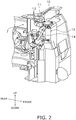
- FIG. 2 is a perspective view illustrating an internal structure of the wheel loader 1 below the cab 5.
- the wheel loader 1 is provided with a filter attachment body 10.
- the filter attachment body 10 is attached to the rear frame 7.
- the filter attachment body 10 may be attached to the vehicle body of the wheel loader 1.
- the vehicle body of the wheel loader 1 signifies a portion other than the work implement 3 and the traveling wheels 4.
- the filter attachment body 10 may be covered by a cladding plate of the wheel loader 1 or may be exposed to the outside of the wheel loader 1.
- the filter attachment body 10 has a bracket 11 and a filter device 12.
- the bracket 11 is attached to the rear frame 7.
- the bracket 11 is fixed directly to the rear frame 7 with bolts 13.
- the method for attaching the bracket 11 is not limited thereto.
- the filter device 12 is attached to the bracket 11.
- the filter device 12 is connected to the unillustrated hydraulic fluid pump via a hydraulic pressure pipe 14. Hydraulic pressure pulsations are transmitted to the filter device 12 when the hydraulic fluid pump discharges the hydraulic fluid.
- FIG. 3 is a side view illustrating a configuration of the filter attachment body 10.
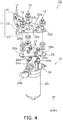
- FIG. 4 is an exploded perspective view illustrating a configuration of the filter attachment body 10.
- the filter attachment body 10 has three sets of attachments 15 in addition to the abovementioned bracket 11 and the filter device 12.
- the bracket 11 has a first attachment plate 21, a second attachment plate 22, and an intermediate part 23.
- the first attachment plate 21 is fixed to the rear frame 7 with the bolts 13.
- the first attachment plate 21 is formed in the shape of a flat plate. While the first attachment plate 21 according to the present embodiment is disposed perpendicular to the horizontal direction, the disposition thereof is not limited. The shape and size of the first attachment plate 21 may be changed as appropriate.
- the second attachment plate 22 is an example of an "attachment plate” according to the present invention.
- the second attachment plate 22 is attached to the filter device 12 via the three attachments 15.
- the second attachment plate 22 is formed in the shape of a flat plate.
- the second attachment plate 22 is disposed substantially perpendicular to the up-down direction.
- the second attachment plate 22 extends substantially in the horizontal direction. As seen in a side view, the angle formed by the second attachment plate 22 with respect to the horizontal direction is preferably five degrees or less.
- Four through-holes 22a and three through-holes 22b are formed in the second attachment plate 22.
- the four through-holes 22a are holes for inserting four bolts 27 described below.
- the three through-holes 22b are holes for mounting the three attachments 15 described below.
- the shape and size of the second attachment plate 22 may be changed as appropriate.
- the intermediate part 23 is joined to the first attachment plate 21 and the second attachment plate 22.
- the shape and size of the intermediate part 23 may be changed as appropriate.
- the filter device 12 has a filter case 24, a filter body 25, a plate 26, and the four bolts 27.
- the filter case 24 has a case body 24a, a first pipe connecting part 24b, a second pipe connecting part 24c, and four bosses 24d.
- the case body 24a is disposed on the filter body 25.
- An oil path linked to the filter body 25 is formed inside the case body 24a.
- the first pipe connecting part 24b is attached to the case body 24a.
- An unillustrated hydraulic pressure pipe is connected to the first pipe connecting part 24b.
- the second pipe connecting part 24c is attached to the case body 24a.
- the hydraulic pressure pipe 14 (see FIG. 2 ) is connected to the second pipe connecting part 24c.
- the filter body 25 has a cylindrical shape that extends in the up-down direction.
- the filter body 25 is disposed below the filter case 24.
- the filter body 25 is attached to the case body 24a.
- the filter body 25 can be attached to and detached from the case body 24a.
- the filter body 25 can be replaced with a new filter body 25.
- the center of gravity 12P of the filter device 12 is located in the filter body 25.
- the plate 26 is a member for attaching the three attachments 15 to the filter device 12.
- the plate 26 is disposed between the second attachment plate 22 of the bracket 11 and the filter case 24.
- the plate 26 is formed in the shape of a flat plate.
- the plate 26 is disposed substantially parallel to the second attachment plate 22 of the bracket 11.
- the shape and size of the plate 26 may be changed as appropriate.
- Four through-holes 26a and three through-holes 26b are formed in the plate 26.
- the three through-holes 26b are located outside of the four through-holes 26a.
- the four bolts 27 are an example of the "plurality of second coupling members" according to the present invention.
- the four bolts 27 couple the plate 26 and the filter case 24.
- the four bolts 27 are inserted through the four through-holes 26a of the plate 26 and are fastened to the four bosses 24d of the filter case 24. While four bolts 27 are used in the present embodiment, the number of the bolts 27 may be changed as appropriate.
- FIG. 5 is a cross-sectional view illustrating a configuration of the attachments 15. As illustrated in FIG. 5 , the attachment 15 has a bolt 30 and an elastic member 31.
- the bolt 30 is an example of the "first coupling member" according to the present invention.
- the bolt 30 couples the second attachment plate 22 of the bracket 11 and the plate 26 of the filter device 12 via the elastic members 31.
- the bolt 30 is inserted into a collar 32 and the through-hole 26b of the plate 26.
- the top part (upper end part) of the bolt 30 is disposed on the elastic member 31 via a washer 33.
- the lower end part of the bolt 30 is fastened to a nut 26c fixed at the lower surface of the plate 26.
- the elastic members 31 are formed in an annular shape or a cylindrical shape.
- the elastic members 31 are interposed between the bracket 11 and the filter device 12.
- the elastic members 31 not only suppress the transmission of vibrations from the filter device 12 to the bracket 11, but also suppress the vibration of the filter device 12 itself.
- the elastic members 31 may be configured of a synthetic rubber such as chloroprene rubber, but are not limited in this way.
- the elastic member 31 includes a first elastic part 31a, a second elastic part 31b, and the collar 32.
- the first elastic part 31a is disposed between the second attachment plate 22 and the plate 26.
- the first elastic part 31a is sandwiched between the second attachment plate 22 and a washer 34 because the washer 34 is disposed on the plate 26.
- the second elastic part 31b is disposed between the second attachment plate 22 and the top part of the bolt 30.
- the second elastic part 31b is sandwiched between the second attachment plate 22 and the washer 33 because the washer 33 is disposed between the top part of the bolt 30 and the elastic member 31.
- the elastic member 31 may include one elastic part or may include three or more elastic parts.
- the collar 32 is inserted through the first elastic part 31a, the second elastic part 31b, and the second attachment plate 22.
- the bolt 30 is inserted inside the collar 32.
- the collar 32 is disposed between the plate 26 and the top part of the bolt 30.
- the collar 32 is sandwiched between the washer 33 and the washer 34.
- the collar 32 suppresses the entire elastic member 31 from being excessively crushed.
- the collar 32 can be configured by a metal material such as steel, but is not limited in this way.
- FIG. 6 is a top view of the second attachment plate 22.
- a figure 31Q is drawn when respective geometric centers 31P of the three elastic members 31 are linked by straight lines when viewed from the top view of the attachment plate 22.
- the figure 31Q which is drawn by linking the respective geometric centers 31P of the three elastic members 31 with straight lines, assumes a triangular shape because three elastic members 31 are disposed.
- a geometric center 25P of the filter body 25 overlaps the figure 31Q when viewed from the top view of the attachment plate 22.
- the three elastic members 31 are each located outside of the filter body 25 in the top view of the second attachment plate 22.
- the vibrations of the filter device 12 can be widely received over the range of the figure 31Q, whereby the transmission of the vibrations of the filter device 12 to the bracket 11 can be effectively suppressed even when the filter device 12 vibrates due to hydraulic pressure pulsations.
- the compression of a portion of the elastic members 31 can be suppressed because the vibrations of the filter device 12 are received over the range of the figure 31Q. As a result, the vibrations of the filter device 12 itself can be effectively suppressed.
- the center of gravity 12P (see FIG. 3 ) of the filter device 12 overlaps the figure 31Q when viewed from the top view of the attachment plate 22. As a result, the transmission of the vibrations of the filter device 12 to the bracket 11 can be even more effectively suppressed and the vibration of the filter device 12 can be more effectively suppressed.
- the matter of a certain object "overlapping the figure 31Q" is a concept that includes the object being located inside the figure 31Q and the object being located on the outer edge of the figure 31Q.
- the four bolts 27 are located inside of the filter body 25 when viewed from the top view of the attachment plate 22. In this way, even when the four bolts 27 are disposed in a narrow range, the three elastic members 31 can be disposed well apart from each other due to the plate 26 being interposed as described above. As a result, the size of the filter device 12 can be made smaller because the four bosses 24d can be disposed in a compact manner to the filter case 24.
Landscapes
- Chemical & Material Sciences (AREA)
- Engineering & Computer Science (AREA)
- Chemical Kinetics & Catalysis (AREA)
- General Engineering & Computer Science (AREA)
- Mining & Mineral Resources (AREA)
- Civil Engineering (AREA)
- Structural Engineering (AREA)
- Mechanical Engineering (AREA)
- Combustion & Propulsion (AREA)
- Vibration Prevention Devices (AREA)
- Arrangement Of Transmissions (AREA)
- Filtration Of Liquid (AREA)
- Details Of Reciprocating Pumps (AREA)
- Connection Of Plates (AREA)
- Cooling, Air Intake And Gas Exhaust, And Fuel Tank Arrangements In Propulsion Units (AREA)
- Motor Power Transmission Devices (AREA)
- Details And Applications Of Rotary Liquid Pumps (AREA)
Abstract
Description
- The present invention relates to a filter attachment body and a work vehicle.
- Conventionally, a work vehicle (such as a wheel loader or a forklift) is provided with a pump (such as a hydraulic fluid pump or a fuel pump) for discharging a fluid and a filter device for filtering the fluid. The filter device is attached to the vehicle body.
- A pulsation when the pump discharges the fluid is transmitted not only as noise to an operator sitting in the operator's seat due to solid propagation from the filter device through the vehicle body to the operator's seat, but also is transmitted as noise outside the work vehicle due to air-borne propagation of the pulsation of the filter device itself.
- Accordingly, Patent Document No. 1 proposes a method for suppressing noise caused by the pulsation of the pump by interposing an elastic member between a bracket attached to the vehicle body frame and the filter device attached to the bracket.
- Patent Document No. 1:
Japanese Patent Laid-open No. 2006-188118 - However, further improvement is desired in the method of Patent Document No. 1 since the elastic member is likely to be partially compressed and unable to sufficiently suppress the noise.
- An object of the present invention is to provide a filter attachment body that can suppress noise caused by pulsation of a pump, and to provide a work vehicle.
- A filter attachment body is attached to a vehicle body of a work vehicle provided with a pump. The filter attachment body comprises a bracket attached to the vehicle body, a filter device attached to the bracket, and a plurality of elastic members interposed between the bracket and the filter device. The bracket has an attachment plate to which the filter device is attached. The attachment plate is disposed substantially perpendicular to the up-down direction. The filter device has a filter case connected to the pump, and a filter body attached to the filter case. A geometric center of the filter body overlaps a figure drawn by linking each of the plurality of elastic members with straight lines when viewed from a top view of the attachment plate. At least a portion of at least one elastic member among the plurality of elastic members is located outside of the filter body when viewed from the top view of the attachment plate.
- According to the present invention, there are provided a filter attachment body that can suppress noise caused by pulsation of a pump, and a work vehicle.
-
-
FIG. 1 is a side view illustrating a configuration of a wheel loader according to an embodiment. -
FIG. 2 is a perspective view illustrating an internal structure of the wheel loader according to the embodiment. -
FIG. 3 is a side view illustrating a configuration of a filter attachment body according to the embodiment. -
FIG. 4 is an exploded perspective view illustrating a configuration of the filter attachment body according to the embodiment. -
FIG. 5 is a cross-sectional view illustrating a configuration of an attachment according to the embodiment. -
FIG. 6 is a top view of a second attachment plate according to the embodiment. - A wheel loader 1 according to an embodiment of the present invention will be explained below with reference to the drawings. The wheel loader 1 is an example of a "work vehicle" according to the present invention. In the following explanations, "up," "down," "front," "rear," "left," and "right" indicate directions relative to the state of looking forward from the driver's seat. The "front-back direction" signifies the front-back direction of the vehicle. The "vehicle width direction" signifies the left-right direction of the vehicle. The "up-down direction" signifies the vertical direction of the vehicle and a direction perpendicular to the vehicle width direction. The "up-down direction" may not coincide with the vertical direction.
-
FIG. 1 is a side view of a configuration of the wheel loader 1 according to an embodiment. - The wheel loader 1 is provided with a
vehicle body frame 2, a work implement 3, a plurality oftraveling wheels 4, and acab 5. - The
vehicle body frame 2 is an articulated type and includes a front frame 6 and a rear frame 7. The front frame 6 is disposed in front of the rear frame 7. - The
work implement 3 is mounted to a front part of the front frame 6. The work implement 3 has aboom 8 and abucket 9. Theboom 8 is rotatably attached to thevehicle body frame 2. Thebucket 9 is rotatably attached to the tip of theboom 8. The wheel loader 1 is provided with a hydraulic fluid pump (not illustrated) that discharges hydraulic fluid for driving the work implement 3. Various types of pumps such as a gear pump or a piston pump can be used as the hydraulic fluid pump. - A pair of the
traveling wheels 4 are attached to the left and right of the front frame 6. A pair of thetraveling wheels 4 are also attached to the left and right of the rear frame 7. - The
cab 5 is disposed on the rear frame 7. The operator's seat, various operating members, and a display device, etc. are disposed inside thecab 5. -
FIG. 2 is a perspective view illustrating an internal structure of the wheel loader 1 below thecab 5. - The wheel loader 1 is provided with a
filter attachment body 10. Thefilter attachment body 10 is attached to the rear frame 7. Thefilter attachment body 10 may be attached to the vehicle body of the wheel loader 1. The vehicle body of the wheel loader 1 signifies a portion other than the work implement 3 and thetraveling wheels 4. Thefilter attachment body 10 may be covered by a cladding plate of the wheel loader 1 or may be exposed to the outside of the wheel loader 1. - The
filter attachment body 10 has abracket 11 and afilter device 12. - The
bracket 11 is attached to the rear frame 7. Thebracket 11 is fixed directly to the rear frame 7 withbolts 13. However, the method for attaching thebracket 11 is not limited thereto. - The
filter device 12 is attached to thebracket 11. Thefilter device 12 is connected to the unillustrated hydraulic fluid pump via ahydraulic pressure pipe 14. Hydraulic pressure pulsations are transmitted to thefilter device 12 when the hydraulic fluid pump discharges the hydraulic fluid. -
FIG. 3 is a side view illustrating a configuration of thefilter attachment body 10.FIG. 4 is an exploded perspective view illustrating a configuration of thefilter attachment body 10. - The
filter attachment body 10 has three sets ofattachments 15 in addition to theabovementioned bracket 11 and thefilter device 12. - The
bracket 11 has afirst attachment plate 21, asecond attachment plate 22, and anintermediate part 23. - The
first attachment plate 21 is fixed to the rear frame 7 with thebolts 13. Thefirst attachment plate 21 is formed in the shape of a flat plate. While thefirst attachment plate 21 according to the present embodiment is disposed perpendicular to the horizontal direction, the disposition thereof is not limited. The shape and size of thefirst attachment plate 21 may be changed as appropriate. - The
second attachment plate 22 is an example of an "attachment plate" according to the present invention. Thesecond attachment plate 22 is attached to thefilter device 12 via the threeattachments 15. Thesecond attachment plate 22 is formed in the shape of a flat plate. Thesecond attachment plate 22 is disposed substantially perpendicular to the up-down direction. Thesecond attachment plate 22 extends substantially in the horizontal direction. As seen in a side view, the angle formed by thesecond attachment plate 22 with respect to the horizontal direction is preferably five degrees or less. Four through-holes 22a and three through-holes 22b are formed in thesecond attachment plate 22. The four through-holes 22a are holes for inserting fourbolts 27 described below. The three through-holes 22b are holes for mounting the threeattachments 15 described below. The shape and size of thesecond attachment plate 22 may be changed as appropriate. - The
intermediate part 23 is joined to thefirst attachment plate 21 and thesecond attachment plate 22. The shape and size of theintermediate part 23 may be changed as appropriate. - The
filter device 12 has afilter case 24, afilter body 25, aplate 26, and the fourbolts 27. - The
filter case 24 has acase body 24a, a firstpipe connecting part 24b, a secondpipe connecting part 24c, and fourbosses 24d. Thecase body 24a is disposed on thefilter body 25. An oil path linked to thefilter body 25 is formed inside thecase body 24a. The firstpipe connecting part 24b is attached to thecase body 24a. An unillustrated hydraulic pressure pipe is connected to the firstpipe connecting part 24b. The secondpipe connecting part 24c is attached to thecase body 24a. The hydraulic pressure pipe 14 (seeFIG. 2 ) is connected to the secondpipe connecting part 24c. - The
filter body 25 has a cylindrical shape that extends in the up-down direction. Thefilter body 25 is disposed below thefilter case 24. Thefilter body 25 is attached to thecase body 24a. Thefilter body 25 can be attached to and detached from thecase body 24a. When the filtering function of thefilter body 25 has deteriorated, thefilter body 25 can be replaced with anew filter body 25. As illustrated inFIG. 3 , the center ofgravity 12P of thefilter device 12 is located in thefilter body 25. - The
plate 26 is a member for attaching the threeattachments 15 to thefilter device 12. Theplate 26 is disposed between thesecond attachment plate 22 of thebracket 11 and thefilter case 24. Theplate 26 is formed in the shape of a flat plate. Theplate 26 is disposed substantially parallel to thesecond attachment plate 22 of thebracket 11. The shape and size of theplate 26 may be changed as appropriate. Four through-holes 26a and three through-holes 26b are formed in theplate 26. The three through-holes 26b are located outside of the four through-holes 26a. - The four
bolts 27 are an example of the "plurality of second coupling members" according to the present invention. The fourbolts 27 couple theplate 26 and thefilter case 24. The fourbolts 27 are inserted through the four through-holes 26a of theplate 26 and are fastened to the fourbosses 24d of thefilter case 24. While fourbolts 27 are used in the present embodiment, the number of thebolts 27 may be changed as appropriate. - The three sets of
attachments 15 are members for attaching thefilter device 12 to thebracket 11.FIG. 5 is a cross-sectional view illustrating a configuration of theattachments 15. As illustrated inFIG. 5 , theattachment 15 has abolt 30 and anelastic member 31. - The
bolt 30 is an example of the "first coupling member" according to the present invention. Thebolt 30 couples thesecond attachment plate 22 of thebracket 11 and theplate 26 of thefilter device 12 via theelastic members 31. Thebolt 30 is inserted into acollar 32 and the through-hole 26b of theplate 26. The top part (upper end part) of thebolt 30 is disposed on theelastic member 31 via awasher 33. The lower end part of thebolt 30 is fastened to anut 26c fixed at the lower surface of theplate 26. - The
elastic members 31 are formed in an annular shape or a cylindrical shape. Theelastic members 31 are interposed between thebracket 11 and thefilter device 12. Theelastic members 31 not only suppress the transmission of vibrations from thefilter device 12 to thebracket 11, but also suppress the vibration of thefilter device 12 itself. Theelastic members 31 may be configured of a synthetic rubber such as chloroprene rubber, but are not limited in this way. - In the present embodiment, the
elastic member 31 includes a firstelastic part 31a, a secondelastic part 31b, and thecollar 32. - The first
elastic part 31a is disposed between thesecond attachment plate 22 and theplate 26. In the present embodiment, the firstelastic part 31a is sandwiched between thesecond attachment plate 22 and awasher 34 because thewasher 34 is disposed on theplate 26. The secondelastic part 31b is disposed between thesecond attachment plate 22 and the top part of thebolt 30. In the present embodiment, the secondelastic part 31b is sandwiched between thesecond attachment plate 22 and thewasher 33 because thewasher 33 is disposed between the top part of thebolt 30 and theelastic member 31. In this way, workability when assembling theattachments 15 can be improved because theelastic member 31 is configured by two elastic parts in the present embodiment. However, theelastic member 31 may include one elastic part or may include three or more elastic parts. - The
collar 32 is inserted through the firstelastic part 31a, the secondelastic part 31b, and thesecond attachment plate 22. Thebolt 30 is inserted inside thecollar 32. Thecollar 32 is disposed between theplate 26 and the top part of thebolt 30. Thecollar 32 is sandwiched between thewasher 33 and thewasher 34. Thecollar 32 suppresses the entireelastic member 31 from being excessively crushed. Thecollar 32 can be configured by a metal material such as steel, but is not limited in this way. -
FIG. 6 is a top view of thesecond attachment plate 22. - A figure 31Q is drawn when respective
geometric centers 31P of the threeelastic members 31 are linked by straight lines when viewed from the top view of theattachment plate 22. In the present embodiment, the figure 31Q, which is drawn by linking the respectivegeometric centers 31P of the threeelastic members 31 with straight lines, assumes a triangular shape because threeelastic members 31 are disposed. - A
geometric center 25P of thefilter body 25 overlaps the figure 31Q when viewed from the top view of theattachment plate 22. Moreover, the threeelastic members 31 are each located outside of thefilter body 25 in the top view of thesecond attachment plate 22. As a result, the vibrations of thefilter device 12 can be widely received over the range of the figure 31Q, whereby the transmission of the vibrations of thefilter device 12 to thebracket 11 can be effectively suppressed even when thefilter device 12 vibrates due to hydraulic pressure pulsations. Moreover, the compression of a portion of theelastic members 31 can be suppressed because the vibrations of thefilter device 12 are received over the range of the figure 31Q. As a result, the vibrations of thefilter device 12 itself can be effectively suppressed. - The center of
gravity 12P (seeFIG. 3 ) of thefilter device 12 overlaps the figure 31Q when viewed from the top view of theattachment plate 22. As a result, the transmission of the vibrations of thefilter device 12 to thebracket 11 can be even more effectively suppressed and the vibration of thefilter device 12 can be more effectively suppressed. - The matter of a certain object "overlapping the figure 31Q" is a concept that includes the object being located inside the figure 31Q and the object being located on the outer edge of the figure 31Q.
- Moreover, the four
bolts 27 are located inside of thefilter body 25 when viewed from the top view of theattachment plate 22. In this way, even when the fourbolts 27 are disposed in a narrow range, the threeelastic members 31 can be disposed well apart from each other due to theplate 26 being interposed as described above. As a result, the size of thefilter device 12 can be made smaller because the fourbosses 24d can be disposed in a compact manner to thefilter case 24. - Although an embodiment of the present invention has been described so far, the present invention is not limited to the above embodiment and various modifications may be made within the scope of the invention.
- (A) While the
filter attachment body 10 has three sets ofattachments 15 in the above embodiment, the present invention is not limited in this way. Thefilter attachment body 10 may have two or more sets ofattachments 15. For example, when thefilter attachment body 10 has two sets ofattachments 15, the figure 31Q is drawn as a "straight line" when linking the respectivegeometric centers 31P of the twoelastic members 31 with a straight line when viewed from the top view of theattachment plate 22. In addition, when thefilter attachment body 10 has five sets ofattachments 15, the figure 31Q is drawn as a "five-sided shape" when linking the respectivegeometric centers 31P of the fiveelastic members 31 with straight lines when viewed from the top view of theattachment plate 22. - (B) While the figure 31Q is drawn by linking the respective
geometric centers 31P of the threeelastic members 31 with straight lines as illustrated inFIG. 6 in the above embodiment, the present invention is not limited in this way. For example, the figure 31Q may be drawn by linking the respective outermost edges of the threeelastic members 31 with straight lines. - (C) While the three
elastic members 31 are each located outside of thefilter body 25 when viewed from the top view of theattachment plate 22 in the above embodiment, the present invention is not limited in this way. At least oneelastic member 31 of the threeelastic members 31 may be located outside of thefilter body 25 when viewed from the top view of theattachment plate 22. Moreover, it is not necessary for all of theelastic members 31 to be located outside of thefilter body 25 and at least a portion of theelastic members 31 may be positioned outside of thefilter body 25. - (D) While the
filter device 12 has theplate 26 in the above embodiment, the present invention is not limited in this way. Theplate 26 may not be used so long as threebosses 24d are provided to thefilter case 24 so as to correspond to the positions of the threeelastic members 31. - (E) While the
attachments 15 each have thecollar 32, thewasher 33, and thewasher 34 in the above embodiment, said members may be used optionally. - (F) While the wheel loader 1 has been explained as an example of the work vehicle in the above embodiment, the
filter attachment body 10 according to the present invention is widely applicable to other work vehicles such as a forklift. - (G) While the
filter attachment body 10 is connected to the hydraulic fluid pump in the above embodiment, the present invention is not limited in this way. Thefilter attachment body 10 can be widely applied to any pump that discharges a fluid. Therefore, thefilter attachment body 10 can be applied not only to a pump that discharges a liquid such as a hydro-static transmission (HST) hydraulic pump, a fuel pump, a urea water pump, or a water pump, but may also be applied to a pump that discharges a gas. -
- 1:
- Wheel loader (example of work vehicle)
- 10:
- Filter attachment body
- 11:
- Bracket
- 22:
- Second attachment plate (example of attachment plate)
- 12:
- Filter device
- 12P:
- Center of gravity of filter device
- 24:
- Filter case
- 25:
- Filter body
- 25P:
- Geometric center of filter body
- 26:
- Plate
- 27:
- Bolt (example of second coupling member)
- 15:
- Attachment
- 30:
- Bolt (example of first coupling member)
- 31:
- Elastic member
- 31a:
- First elastic part
- 31b:
- Second elastic part
- 31P:
- Geometric center of elastic member
- 31Q:
- Figure
Claims (6)
- A filter attachment body attached to a vehicle body of a work vehicle provided with a pump, the filter attachment body comprising:a bracket attached to the vehicle body;a filter device attached to the bracket; anda plurality of elastic members interposed between the bracket and the filter device; whereinthe bracket has an attachment plate to which the filter device is attached,the attachment plate is disposed substantially perpendicular to the up-down direction,the filter device has a filter case connected to the pump, and a filter body attached to the filter case,a geometric center of the filter body overlaps a figure drawn by linking each of the plurality of elastic members with straight lines when viewed from a top view of the attachment plate, andat least a portion of at least one elastic member among the plurality of elastic members is located outside of the filter body when viewed from the top view of the attachment plate.
- The filter attachment body according to claim 1, further comprising:a plurality of first coupling members that couple the bracket and the filter device via the plurality of elastic members, whereineach of the plurality of elastic members has a first elastic part disposed between the bracket and the filter device and a second elastic part disposed between the bracket and the first coupling member.
- The filter attachment body according to claim 1 or claim 2, whereinthe filter device has a plate disposed between the attachment plate and the filter case, and a plurality of second coupling members that couple the plate and the filter case, andthe plurality of second elastic parts are located inside of the filter body when viewed from the top view of the attachment plate.
- The filter attachment body according to any one of claims 1 to 3, wherein
a center of gravity of the filter device overlaps the figure when viewed from the top view of the attachment plate. - The filter attachment body according to any one of claims 1 to 4, wherein
the figure is a figure drawn by linking respective geometric centers of the plurality of elastic members with straight lines. - A work vehicle comprisinga vehicle body,a work implement attached to the vehicle body,a pump configured to supply hydraulic fluid to the work implement, andthe filter attachment body described in any one of claims 1 to 5.
Applications Claiming Priority (2)
| Application Number | Priority Date | Filing Date | Title |
|---|---|---|---|
| JP2019051088A JP7355510B2 (en) | 2019-03-19 | 2019-03-19 | Filter mounting body and work vehicle |
| PCT/JP2020/011729 WO2020189680A1 (en) | 2019-03-19 | 2020-03-17 | Filter-attaching member and work vehicle |
Publications (3)
| Publication Number | Publication Date |
|---|---|
| EP3906989A1 true EP3906989A1 (en) | 2021-11-10 |
| EP3906989A4 EP3906989A4 (en) | 2022-08-31 |
| EP3906989B1 EP3906989B1 (en) | 2025-08-06 |
Family
ID=72520125
Family Applications (1)
| Application Number | Title | Priority Date | Filing Date |
|---|---|---|---|
| EP20773790.9A Active EP3906989B1 (en) | 2019-03-19 | 2020-03-17 | Filter-attaching member and work vehicle |
Country Status (5)
| Country | Link |
|---|---|
| US (1) | US12239926B2 (en) |
| EP (1) | EP3906989B1 (en) |
| JP (1) | JP7355510B2 (en) |
| CN (1) | CN113412142B (en) |
| WO (1) | WO2020189680A1 (en) |
Families Citing this family (1)
| Publication number | Priority date | Publication date | Assignee | Title |
|---|---|---|---|---|
| US20250314184A1 (en) * | 2023-11-21 | 2025-10-09 | Matthew Risley | Oil catch can |
Family Cites Families (8)
| Publication number | Priority date | Publication date | Assignee | Title |
|---|---|---|---|---|
| JPS6096Y2 (en) * | 1980-01-29 | 1985-01-05 | セイレイ工業株式会社 | Suction strainer mounting device |
| JPS5719215U (en) * | 1980-07-08 | 1982-02-01 | ||
| JP4415399B2 (en) | 1998-09-11 | 2010-02-17 | 三和パッキング工業株式会社 | Combination parts and manufacturing method thereof |
| JP2006188118A (en) * | 2005-01-05 | 2006-07-20 | Shin Caterpillar Mitsubishi Ltd | Oil filter of hst charge circuit of working vehicle |
| JP2013210079A (en) | 2012-03-30 | 2013-10-10 | Hitachi Automotive Systems Ltd | Fastening member and compressor apparatus |
| JP6008751B2 (en) | 2013-02-04 | 2016-10-19 | 小島プレス工業株式会社 | Vehicle parts fittings |
| JP6698491B2 (en) | 2016-09-29 | 2020-05-27 | 株式会社クボタ | Work machine |
| CN206738318U (en) | 2017-01-23 | 2017-12-12 | 华南建材(深圳)有限公司 | A kind of wallboard Flexible Connector peculiar to vessel |
-
2019
- 2019-03-19 JP JP2019051088A patent/JP7355510B2/en active Active
-
2020
- 2020-03-17 US US17/426,911 patent/US12239926B2/en active Active
- 2020-03-17 WO PCT/JP2020/011729 patent/WO2020189680A1/en not_active Ceased
- 2020-03-17 EP EP20773790.9A patent/EP3906989B1/en active Active
- 2020-03-17 CN CN202080012627.2A patent/CN113412142B/en active Active
Also Published As
| Publication number | Publication date |
|---|---|
| US12239926B2 (en) | 2025-03-04 |
| CN113412142A (en) | 2021-09-17 |
| JP7355510B2 (en) | 2023-10-03 |
| JP2020152182A (en) | 2020-09-24 |
| CN113412142B (en) | 2022-09-13 |
| EP3906989B1 (en) | 2025-08-06 |
| US20220096973A1 (en) | 2022-03-31 |
| WO2020189680A1 (en) | 2020-09-24 |
| EP3906989A4 (en) | 2022-08-31 |
Similar Documents
| Publication | Publication Date | Title |
|---|---|---|
| JP4987644B2 (en) | Upper frame structure that supports the cab of construction machinery | |
| US9238901B2 (en) | Supporting mechanism, exhaust treatment unit, and wheel loader | |
| US9441527B2 (en) | Supporting mechanism, exhaust treatment unit, and wheel loader | |
| US20090121521A1 (en) | Frame Structure for Working Vehicle | |
| JP3782004B2 (en) | Tractor with front loader and backhoe | |
| JP2010007525A (en) | Construction machine | |
| US7874390B2 (en) | Working machine | |
| EP3906989B1 (en) | Filter-attaching member and work vehicle | |
| US10024026B2 (en) | Front loader frame, front loader equipped with front loader frame, and work vehicle equipped with front loader | |
| US8979131B2 (en) | Fuel tank mounting | |
| CN104520515A (en) | Controller assembly and cab for operation machinery | |
| US20070278811A1 (en) | System for operably coupling a vehicle cab to a vehicle | |
| JP2015044525A (en) | vehicle | |
| CN105829197A (en) | tractor | |
| JP3917448B2 (en) | Tractor front guard device | |
| JP4292021B2 (en) | Tractor fuel tank | |
| JP2013107516A (en) | Stepped outrigger structure | |
| CN204755479U (en) | Oil circuit cleaning device | |
| JP3583619B2 (en) | Vehicle fuel piping arrangement | |
| JP2006188118A (en) | Oil filter of hst charge circuit of working vehicle | |
| CN112523283A (en) | Construction machine | |
| JP2016210343A (en) | Vibration isolation structure of construction machine | |
| JP4619170B2 (en) | Swivel work machine | |
| CN201442573U (en) | A front winch device for a vehicle | |
| JP6908567B2 (en) | Construction machinery |
Legal Events
| Date | Code | Title | Description |
|---|---|---|---|
| STAA | Information on the status of an ep patent application or granted ep patent |
Free format text: STATUS: THE INTERNATIONAL PUBLICATION HAS BEEN MADE |
|
| PUAI | Public reference made under article 153(3) epc to a published international application that has entered the european phase |
Free format text: ORIGINAL CODE: 0009012 |
|
| STAA | Information on the status of an ep patent application or granted ep patent |
Free format text: STATUS: REQUEST FOR EXAMINATION WAS MADE |
|
| 17P | Request for examination filed |
Effective date: 20210804 |
|
| AK | Designated contracting states |
Kind code of ref document: A1 Designated state(s): AL AT BE BG CH CY CZ DE DK EE ES FI FR GB GR HR HU IE IS IT LI LT LU LV MC MK MT NL NO PL PT RO RS SE SI SK SM TR |
|
| DAV | Request for validation of the european patent (deleted) | ||
| DAX | Request for extension of the european patent (deleted) | ||
| A4 | Supplementary search report drawn up and despatched |
Effective date: 20220803 |
|
| RIC1 | Information provided on ipc code assigned before grant |
Ipc: B01D 35/30 20060101ALI20220728BHEP Ipc: B01D 35/00 20060101ALI20220728BHEP Ipc: B60K 17/08 20060101ALI20220728BHEP Ipc: B01D 35/02 20060101AFI20220728BHEP |
|
| STAA | Information on the status of an ep patent application or granted ep patent |
Free format text: STATUS: EXAMINATION IS IN PROGRESS |
|
| 17Q | First examination report despatched |
Effective date: 20230908 |
|
| GRAP | Despatch of communication of intention to grant a patent |
Free format text: ORIGINAL CODE: EPIDOSNIGR1 |
|
| STAA | Information on the status of an ep patent application or granted ep patent |
Free format text: STATUS: GRANT OF PATENT IS INTENDED |
|
| INTG | Intention to grant announced |
Effective date: 20250324 |
|
| GRAS | Grant fee paid |
Free format text: ORIGINAL CODE: EPIDOSNIGR3 |
|
| GRAA | (expected) grant |
Free format text: ORIGINAL CODE: 0009210 |
|
| STAA | Information on the status of an ep patent application or granted ep patent |
Free format text: STATUS: THE PATENT HAS BEEN GRANTED |
|
| AK | Designated contracting states |
Kind code of ref document: B1 Designated state(s): AL AT BE BG CH CY CZ DE DK EE ES FI FR GB GR HR HU IE IS IT LI LT LU LV MC MK MT NL NO PL PT RO RS SE SI SK SM TR |
|
| REG | Reference to a national code |
Ref country code: GB Ref legal event code: FG4D |
|
| REG | Reference to a national code |
Ref country code: CH Ref legal event code: EP |
|
| REG | Reference to a national code |
Ref country code: DE Ref legal event code: R096 Ref document number: 602020056003 Country of ref document: DE |
|
| REG | Reference to a national code |
Ref country code: IE Ref legal event code: FG4D |
|
| REG | Reference to a national code |
Ref country code: NL Ref legal event code: MP Effective date: 20250806 |
|
| PG25 | Lapsed in a contracting state [announced via postgrant information from national office to epo] |
Ref country code: IS Free format text: LAPSE BECAUSE OF FAILURE TO SUBMIT A TRANSLATION OF THE DESCRIPTION OR TO PAY THE FEE WITHIN THE PRESCRIBED TIME-LIMIT Effective date: 20251206 |
|
| PG25 | Lapsed in a contracting state [announced via postgrant information from national office to epo] |
Ref country code: NO Free format text: LAPSE BECAUSE OF FAILURE TO SUBMIT A TRANSLATION OF THE DESCRIPTION OR TO PAY THE FEE WITHIN THE PRESCRIBED TIME-LIMIT Effective date: 20251106 |
|
| REG | Reference to a national code |
Ref country code: LT Ref legal event code: MG9D |
|
| PG25 | Lapsed in a contracting state [announced via postgrant information from national office to epo] |
Ref country code: PT Free format text: LAPSE BECAUSE OF FAILURE TO SUBMIT A TRANSLATION OF THE DESCRIPTION OR TO PAY THE FEE WITHIN THE PRESCRIBED TIME-LIMIT Effective date: 20251209 |
|
| PG25 | Lapsed in a contracting state [announced via postgrant information from national office to epo] |
Ref country code: FI Free format text: LAPSE BECAUSE OF FAILURE TO SUBMIT A TRANSLATION OF THE DESCRIPTION OR TO PAY THE FEE WITHIN THE PRESCRIBED TIME-LIMIT Effective date: 20250806 |
|
| PG25 | Lapsed in a contracting state [announced via postgrant information from national office to epo] |
Ref country code: NL Free format text: LAPSE BECAUSE OF FAILURE TO SUBMIT A TRANSLATION OF THE DESCRIPTION OR TO PAY THE FEE WITHIN THE PRESCRIBED TIME-LIMIT Effective date: 20250806 Ref country code: HR Free format text: LAPSE BECAUSE OF FAILURE TO SUBMIT A TRANSLATION OF THE DESCRIPTION OR TO PAY THE FEE WITHIN THE PRESCRIBED TIME-LIMIT Effective date: 20250806 |
|
| PG25 | Lapsed in a contracting state [announced via postgrant information from national office to epo] |
Ref country code: GR Free format text: LAPSE BECAUSE OF FAILURE TO SUBMIT A TRANSLATION OF THE DESCRIPTION OR TO PAY THE FEE WITHIN THE PRESCRIBED TIME-LIMIT Effective date: 20251107 |
|
| PG25 | Lapsed in a contracting state [announced via postgrant information from national office to epo] |
Ref country code: SE Free format text: LAPSE BECAUSE OF FAILURE TO SUBMIT A TRANSLATION OF THE DESCRIPTION OR TO PAY THE FEE WITHIN THE PRESCRIBED TIME-LIMIT Effective date: 20250806 |
|
| PG25 | Lapsed in a contracting state [announced via postgrant information from national office to epo] |
Ref country code: LV Free format text: LAPSE BECAUSE OF FAILURE TO SUBMIT A TRANSLATION OF THE DESCRIPTION OR TO PAY THE FEE WITHIN THE PRESCRIBED TIME-LIMIT Effective date: 20250806 |
|
| PG25 | Lapsed in a contracting state [announced via postgrant information from national office to epo] |
Ref country code: PL Free format text: LAPSE BECAUSE OF FAILURE TO SUBMIT A TRANSLATION OF THE DESCRIPTION OR TO PAY THE FEE WITHIN THE PRESCRIBED TIME-LIMIT Effective date: 20250806 Ref country code: BG Free format text: LAPSE BECAUSE OF FAILURE TO SUBMIT A TRANSLATION OF THE DESCRIPTION OR TO PAY THE FEE WITHIN THE PRESCRIBED TIME-LIMIT Effective date: 20250806 |
|
| PG25 | Lapsed in a contracting state [announced via postgrant information from national office to epo] |
Ref country code: RS Free format text: LAPSE BECAUSE OF FAILURE TO SUBMIT A TRANSLATION OF THE DESCRIPTION OR TO PAY THE FEE WITHIN THE PRESCRIBED TIME-LIMIT Effective date: 20251106 |
|
| PG25 | Lapsed in a contracting state [announced via postgrant information from national office to epo] |
Ref country code: ES Free format text: LAPSE BECAUSE OF FAILURE TO SUBMIT A TRANSLATION OF THE DESCRIPTION OR TO PAY THE FEE WITHIN THE PRESCRIBED TIME-LIMIT Effective date: 20250806 |
|
| REG | Reference to a national code |
Ref country code: AT Ref legal event code: MK05 Ref document number: 1821172 Country of ref document: AT Kind code of ref document: T Effective date: 20250806 |
|
| PG25 | Lapsed in a contracting state [announced via postgrant information from national office to epo] |
Ref country code: SM Free format text: LAPSE BECAUSE OF FAILURE TO SUBMIT A TRANSLATION OF THE DESCRIPTION OR TO PAY THE FEE WITHIN THE PRESCRIBED TIME-LIMIT Effective date: 20250806 |
|
| PG25 | Lapsed in a contracting state [announced via postgrant information from national office to epo] |
Ref country code: DK Free format text: LAPSE BECAUSE OF FAILURE TO SUBMIT A TRANSLATION OF THE DESCRIPTION OR TO PAY THE FEE WITHIN THE PRESCRIBED TIME-LIMIT Effective date: 20250806 |
|
| PGFP | Annual fee paid to national office [announced via postgrant information from national office to epo] |
Ref country code: DE Payment date: 20260128 Year of fee payment: 7 |
|
| PG25 | Lapsed in a contracting state [announced via postgrant information from national office to epo] |
Ref country code: AT Free format text: LAPSE BECAUSE OF FAILURE TO SUBMIT A TRANSLATION OF THE DESCRIPTION OR TO PAY THE FEE WITHIN THE PRESCRIBED TIME-LIMIT Effective date: 20250806 |
|
| PG25 | Lapsed in a contracting state [announced via postgrant information from national office to epo] |
Ref country code: IT Free format text: LAPSE BECAUSE OF FAILURE TO SUBMIT A TRANSLATION OF THE DESCRIPTION OR TO PAY THE FEE WITHIN THE PRESCRIBED TIME-LIMIT Effective date: 20250806 |
|
| PG25 | Lapsed in a contracting state [announced via postgrant information from national office to epo] |
Ref country code: CZ Free format text: LAPSE BECAUSE OF FAILURE TO SUBMIT A TRANSLATION OF THE DESCRIPTION OR TO PAY THE FEE WITHIN THE PRESCRIBED TIME-LIMIT Effective date: 20250806 |
|
| PG25 | Lapsed in a contracting state [announced via postgrant information from national office to epo] |
Ref country code: SK Free format text: LAPSE BECAUSE OF FAILURE TO SUBMIT A TRANSLATION OF THE DESCRIPTION OR TO PAY THE FEE WITHIN THE PRESCRIBED TIME-LIMIT Effective date: 20250806 Ref country code: EE Free format text: LAPSE BECAUSE OF FAILURE TO SUBMIT A TRANSLATION OF THE DESCRIPTION OR TO PAY THE FEE WITHIN THE PRESCRIBED TIME-LIMIT Effective date: 20250806 |
|
| REG | Reference to a national code |
Ref country code: DE Ref legal event code: R097 Ref document number: 602020056003 Country of ref document: DE |
|
| PLBE | No opposition filed within time limit |
Free format text: ORIGINAL CODE: 0009261 |
|
| STAA | Information on the status of an ep patent application or granted ep patent |
Free format text: STATUS: NO OPPOSITION FILED WITHIN TIME LIMIT |
|
| REG | Reference to a national code |
Ref country code: CH Ref legal event code: L10 Free format text: ST27 STATUS EVENT CODE: U-0-0-L10-L00 (AS PROVIDED BY THE NATIONAL OFFICE) Effective date: 20260617 |
|
| PG25 | Lapsed in a contracting state [announced via postgrant information from national office to epo] |
Ref country code: LT Free format text: LAPSE BECAUSE OF FAILURE TO SUBMIT A TRANSLATION OF THE DESCRIPTION OR TO PAY THE FEE WITHIN THE PRESCRIBED TIME-LIMIT Effective date: 20250806 |
|
| 26N | No opposition filed |
Effective date: 20260507 |