EP3906369B1 - Temperiervorrichtung für antriebs- und/oder getriebeeinheiten wie tunnelbohrer-getriebe - Google Patents
Temperiervorrichtung für antriebs- und/oder getriebeeinheiten wie tunnelbohrer-getriebe Download PDFInfo
- Publication number
- EP3906369B1 EP3906369B1 EP20710433.2A EP20710433A EP3906369B1 EP 3906369 B1 EP3906369 B1 EP 3906369B1 EP 20710433 A EP20710433 A EP 20710433A EP 3906369 B1 EP3906369 B1 EP 3906369B1
- Authority
- EP
- European Patent Office
- Prior art keywords
- transmission
- heat exchanger
- drive
- ring
- exchanger module
- Prior art date
- Legal status (The legal status is an assumption and is not a legal conclusion. Google has not performed a legal analysis and makes no representation as to the accuracy of the status listed.)
- Active
Links
Images

Classifications
-
- F—MECHANICAL ENGINEERING; LIGHTING; HEATING; WEAPONS; BLASTING
- F16—ENGINEERING ELEMENTS AND UNITS; GENERAL MEASURES FOR PRODUCING AND MAINTAINING EFFECTIVE FUNCTIONING OF MACHINES OR INSTALLATIONS; THERMAL INSULATION IN GENERAL
- F16H—GEARING
- F16H57/00—General details of gearing
- F16H57/04—Features relating to lubrication or cooling or heating
- F16H57/0412—Cooling or heating; Control of temperature
- F16H57/0415—Air cooling or ventilation; Heat exchangers; Thermal insulations
- F16H57/0417—Heat exchangers adapted or integrated in the gearing
-
- E—FIXED CONSTRUCTIONS
- E21—EARTH OR ROCK DRILLING; MINING
- E21D—SHAFTS; TUNNELS; GALLERIES; LARGE UNDERGROUND CHAMBERS
- E21D9/00—Tunnels or galleries, with or without linings; Methods or apparatus for making thereof; Layout of tunnels or galleries
- E21D9/10—Making by using boring or cutting machines
- E21D9/1086—Drives or transmissions specially adapted therefor
-
- F—MECHANICAL ENGINEERING; LIGHTING; HEATING; WEAPONS; BLASTING
- F01—MACHINES OR ENGINES IN GENERAL; ENGINE PLANTS IN GENERAL; STEAM ENGINES
- F01M—LUBRICATING OF MACHINES OR ENGINES IN GENERAL; LUBRICATING INTERNAL COMBUSTION ENGINES; CRANKCASE VENTILATING
- F01M5/00—Heating, cooling, or controlling temperature of lubricant; Lubrication means facilitating engine starting
-
- F—MECHANICAL ENGINEERING; LIGHTING; HEATING; WEAPONS; BLASTING
- F16—ENGINEERING ELEMENTS AND UNITS; GENERAL MEASURES FOR PRODUCING AND MAINTAINING EFFECTIVE FUNCTIONING OF MACHINES OR INSTALLATIONS; THERMAL INSULATION IN GENERAL
- F16H—GEARING
- F16H57/00—General details of gearing
- F16H57/04—Features relating to lubrication or cooling or heating
- F16H57/0412—Cooling or heating; Control of temperature
- F16H57/0415—Air cooling or ventilation; Heat exchangers; Thermal insulations
-
- F—MECHANICAL ENGINEERING; LIGHTING; HEATING; WEAPONS; BLASTING
- F16—ENGINEERING ELEMENTS AND UNITS; GENERAL MEASURES FOR PRODUCING AND MAINTAINING EFFECTIVE FUNCTIONING OF MACHINES OR INSTALLATIONS; THERMAL INSULATION IN GENERAL
- F16H—GEARING
- F16H1/00—Toothed gearings for conveying rotary motion
- F16H1/28—Toothed gearings for conveying rotary motion with gears having orbital motion
- F16H1/46—Systems consisting of a plurality of gear trains each with orbital gears, i.e. systems having three or more central gears
-
- F—MECHANICAL ENGINEERING; LIGHTING; HEATING; WEAPONS; BLASTING
- F16—ENGINEERING ELEMENTS AND UNITS; GENERAL MEASURES FOR PRODUCING AND MAINTAINING EFFECTIVE FUNCTIONING OF MACHINES OR INSTALLATIONS; THERMAL INSULATION IN GENERAL
- F16H—GEARING
- F16H57/00—General details of gearing
- F16H57/04—Features relating to lubrication or cooling or heating
- F16H57/0408—Exchange, draining or filling of transmission lubricant
-
- F—MECHANICAL ENGINEERING; LIGHTING; HEATING; WEAPONS; BLASTING
- F16—ENGINEERING ELEMENTS AND UNITS; GENERAL MEASURES FOR PRODUCING AND MAINTAINING EFFECTIVE FUNCTIONING OF MACHINES OR INSTALLATIONS; THERMAL INSULATION IN GENERAL
- F16H—GEARING
- F16H57/00—General details of gearing
- F16H57/04—Features relating to lubrication or cooling or heating
- F16H57/0434—Features relating to lubrication or cooling or heating relating to lubrication supply, e.g. pumps; Pressure control
- F16H57/0445—Features relating to lubrication or cooling or heating relating to lubrication supply, e.g. pumps; Pressure control for supply of different gearbox casings or sections
-
- F—MECHANICAL ENGINEERING; LIGHTING; HEATING; WEAPONS; BLASTING
- F16—ENGINEERING ELEMENTS AND UNITS; GENERAL MEASURES FOR PRODUCING AND MAINTAINING EFFECTIVE FUNCTIONING OF MACHINES OR INSTALLATIONS; THERMAL INSULATION IN GENERAL
- F16H—GEARING
- F16H57/00—General details of gearing
- F16H57/08—General details of gearing of gearings with members having orbital motion
Definitions
- the present invention generally relates to the cooling and/or heating of drive and/or transmission units of construction machines and similar equipment.
- the invention relates on the one hand to the temperature control device for cooling and/or heating such a drive and/or transmission unit with at least one heat exchanger module which has a fluid jacket through which liquid can flow.
- the invention relates to a drive and/or gear unit with at least two gear and/or drive sections, which are cooled and/or heated by such a temperature control unit.
- the invention also relates to a tunnel boring machine whose transmission is cooled and/or heated by such a temperature control device.
- Temperature control devices for cooling drive and transmission units with a heat exchanger module, which has a fluid jacket through which it can flow are known, for example, from the documents JP 2011 214586 A , WO 2014/069536 A1 or CN 101 285 519 A known.
- the document JP 2011 214586 A also discloses turbulence ridges.
- While cooling of the drive and/or gear unit is often a concern, in very cold environmental conditions, such as when a drill is idle overnight or over the weekend in arctic conditions, it may also be necessary, or at least helpful, to cool the drive and/or gear unit To heat the transmission unit and bring it up to operating temperature, for example to make starting easier and to ensure complete lubrication even when starting in very cold temperatures.
- the present invention is therefore based on the object of providing an improved temperature control device of the type mentioned at the outset, as well as an improved drive and/or gear unit and an improved tunnel boring machine which avoid the disadvantages of the prior art and develop the latter in an advantageous manner.
- a robust temperature control that can withstand even rough construction site conditions is to be achieved by means of a device that is simple in design and easy to replace, which, if necessary, can also be can be subsequently retrofitted to the drive and/or transmission units in which temperature problems have arisen under certain operating conditions.
- the stated object is achieved by a temperature control device according to claim 1, a gear and/or drive unit according to claim 7 and by a tunnel boring machine according to claim 10.
- Preferred developments of the invention are the subject matter of the dependent claims.
- the temperature control device in the form of an independent heat exchanger module that is separate from the transmission and can be inserted in a sandwich-like manner between two transmission and/or drive sections in order to extract or supply heat at the interface of the two transmission and/or drive sections. Due to the modular structure of the gear and/or drive unit on the one hand and the temperature control device on the other hand, a gear and/or drive unit can also be retrofitted in a very simple manner later if temperature problems occur.
- the at least one heat exchanger module of the temperature control device forms a ring body for sandwich-like fitting between two transmission and/or drive sections, which ring body has a central through-hole for passing through a drive element and a connecting flange on opposite end faces for precisely fitting end-side connection to the two transmission and/or drive sections. or has drive sections.
- a drive shaft or a drive wheel or another drive element can be passed through the mentioned through-hole, which connects, for example, two gear stages or two gear and/or drive sections in a force-transmitting or torque-transmitting manner.
- the heat exchanger module can be easily integrated into the drive or transmission unit without the transmission or drive unit having to be specially adapted.
- connection flanges of the annular body of the heat exchanger are to be connected to the flange pattern of the gearbox and/or drive sections Shape-adapted so that the transmission or drive sections can be attached and connected to the connection flanges with a precise fit.
- the transmission or drive sections between which the heat exchanger module is to be fitted in a sandwich-like manner can be connected to the connecting flanges of the heat exchanger in a liquid-tight manner, it being possible for the transmission and/or drive sections mentioned to be fastened to the opposite connecting flanges of the heat exchanger module, in particular with the respective housing parts.
- connection flanges of the annular body of the heat exchanger module can be adapted in shape to the edge connection flanges of two housing parts and can be fastened thereto in a liquid-tight manner, which housing parts together form a transmission housing and/or can form separate housing modules of separate transmission stages.
- the through-flow liquid jacket of the heat exchanger module forms an annular chamber inside the annular body, which extends around the through-hole.
- the coolant can flow around the through-hole and cool the walls of the annular body over a large area and correspondingly absorb and dissipate large amounts of heat.
- the mentioned ring body can have a solid outer ring, on which the two opposing connecting flanges are formed, an inner ring accommodated in the outer ring and two preferably approximately plate-shaped end walls, which Connect the outer and inner rings to one another and delimit the liquid jacket between them, in particular the ring chamber mentioned.
- Such a massive outer ring which can be designed as a solid body, for example made of a metallic material, gives the heat exchanger module sufficient robustness to stably connect the two transmission and/or drive sections to one another and also to protect the heat exchanger module itself against the harsh environmental conditions on a construction site protection.
- the box construction with plate-shaped end walls, which connect the inner and outer rings to one another and delimit the liquid jacket achieves an overall simple structure, with the end walls forming large heat transfer surfaces that can transfer large amounts of heat to the liquid flowing through.
- the end walls mentioned can have significantly lower wall thicknesses than the solid outer ring.
- thin sheet metal plates can be provided as end walls, which can be welded and/or glued to the solid outer ring and the inner ring and/or cast during casting or fastened in a liquid-tight manner in some other way.
- the wall thickness of the plate-shaped end walls can be less than a third or even less than a quarter of the thickness of the outer ring, in particular the axial extent of the outer ring.
- the inner ring can also have a significantly smaller wall thickness than the outer ring.
- the radially measured thickness of the inner ring can be less than 50% of the radially measured thickness of the outer ring, with the inner and outer rings having the same axial extensions, particularly when the plate-shaped end walls are arranged parallel to one another.
- the heat exchanger designed as a ring body can be disk-shaped, in particular in the manner of a salami disk, which has a through-hole in the center.
- a disc-shaped design of the ring body can, for example, by at least approximately parallel Mark end faces.
- the outer and/or inner lateral surface of the ring body which can be formed by the outer lateral side of the outer ring and/or the inner lateral side of the inner ring, can have an approximately cylindrical contour, in particular an approximately circular-cylindrical contour.
- the liquid jacket of the heat exchanger module can have an inlet and an outlet in order to be able to cool the temperature control liquid flowing through it externally, ie outside the heat exchanger module or its liquid chamber, or possibly also to heat it.
- the heat exchanger module can have at least one inflow connection and one outflow connection in order to be able to easily connect an external coolant circuit of the respective machine with corresponding inflow and outflow lines to the heat exchanger module.
- the inflow and outflow connections mentioned can advantageously be provided on the outer ring of the ring body of the heat exchanger module in order to be able to feed the temperature control liquid through the outer ring into the ring chamber and to be able to drain it off again.
- said inlet and said outlet of the annular chamber can be provided next to one another or in the same sector of the annular body of the heat exchanger and separated from one another by a separating web provided in the annular chamber, which divides the annular chamber into two annular regions in the circumferential direction in the manner of a slotted ring.
- the arrangement of the inlet and outlet in the same sector of the annular body or annular chamber ensures that the temperature control liquid runs and circulates through the entire annular chamber, with the aforementioned separating web preventing a flow short circuit and ensuring that the fluid circulates through the entire heat exchanger or the entire annular chamber must flow.
- the inflow and outflow connections mentioned can include liquid-tight coupling means, for example plug-in couplings or screw couplings for connecting heat transfer liquid lines.
- said inlet and outlet can be arranged at the top of the ring body, for example just before and just after 12 o'clock, in order to supply the tempering fluid both at the top and to discharge it at the top.
- Such an arrangement of the inlet and outlet of the temperature control fluid circuit on the upper side ensures that the temperature control fluid flows through the entire liquid jacket, in particular the entire annular chamber.
- turbulence ridges and/or distribution plates are provided in the annular chamber through which the temperature control fluid flows and are arranged radially offset from one another, so that the temperature control liquid must flow back and forth in a meandering or serpentine manner in order to be able to pass the turbulence ridges.
- the turbulence webs mentioned can be arranged alternatingly projecting outwards from the inner ring and inwards from the outer ring.
- the turbulence ridges mentioned can extend over the entire width or thickness of the annular chamber, i.e. are present on both sides of the two plate-shaped end walls, so that only one passage remains at the radially inner end or at the radially outer end of the alternately arranged turbulence ridges.
- the turbulence webs are arranged in such a way that the cooling or heating fluid flows back and forth in a meandering manner between the two plate-shaped end walls which delimit the annular chamber at the end.
- the mentioned turbulence webs each leave a passage gap to one of the two end walls, the turbulence webs adjoining one end wall and the other end wall alternately.
- a meandering flow path which runs back and forth from the inner ring to the outer ring and so on, lengthens the flow path through the annular chamber and accordingly the residence time of the circulating temperature control liquid in the annular chamber, which means that improved heat transfer can be achieved.
- the heat exchanger module can advantageously have a plurality of through-holes in the area of an outer peripheral section of the annular body.
- the aforementioned outer ring can be provided with a plurality of through bores or recesses in order to exchange transmission oil or lubricant from one transmission and/or drive section to the other transmission and/or drive section, even in the area close to the transmission and/or drive section. or to allow drive housing wall.
- a planetary gear stage is provided in one of the transmission sections, which has a ring gear on the outer circumference, lubricant displaced from the toothing on the cavity can escape via the through holes mentioned, so that the displaced oil gives off heat when it comes into direct contact with the heat exchanger module and overheating in the area of the ring gear is avoided.
- Said through holes can be distributed along the circumference of the heat exchanger module.
- Said through-holes can be positioned radially inside the opposing connecting flanges.
- gear stages can be provided on both sides of the heat exchanger module, preferably in the form of planetary gear stages.
- the two gear stages can be connected to one another in order to transmit force and torque by means of a sun gear and/or a planet carrier carrier or which extends through the through-hole of the annular body-shaped heat exchanger module.
- the at least one heat exchanger module can be arranged between the two first gear stages closest to the drive motor, in order to be able to dissipate the thermal load occurring there.
- the power losses and thus the heat generated are greatest in the first, high-speed gear stages in particular, so that the heat load can be reduced particularly efficiently by interposing the heat exchanger module between the first two gear stages.
- several heat exchanger modules of the type mentioned can also be arranged between several adjacent pairs of gear stages, for example between the first and second gear stage and between the second and third gear stage.
- the gear stages mentioned can advantageously each be designed as a planetary gear stage.
- a tunnel boring machine 1 can have a rotatably drivable drill head 2 similar to a milling rotor, which is driven in rotation by a drive motor 3 via a gear unit 4 .
- Said drill head 2 can be driven by the gear unit 4 via a toothed ring, for example, which can be supported by a drill head bearing 5 in a manner known per se.
- the gear unit 4 can be made up of several gear stages, which are connected in series in order to step up or step down the drive speed of the drive motor 3 into the desired rotor speed of the drill head 2, whereby for example three gear stages 4.1, 4.2 and 4.3 can be provided.
- the gear stages mentioned can be planetary stages, each of which can comprise a sun gear 6 , a ring gear 7 and planetary gears 8 which are in engagement therewith and which can be arranged on a planetary carrier 9 . Adjacent planetary stages can be connected to each other at the sun gear and at the web of the planet carrier, cf. figure 1 .
- Said gear stages 4.1, 4.2 and 4.3 can each be designed separately from one another and each have at least approximately cylindrical gear housing parts with which they can be placed one on top of the other, so that the gear unit 4 as a whole is constructed in a modular manner from the multiple gear stages, which are arranged axially one behind the other and connected to one another .
- the first gear stage 4.1 can be connected to the drive motor 3, in which case, for example, a motor output shaft 10 can be coupled in a torque-proof manner to the sun gear 4 of the first gear stage 4.1.
- the output shaft of the last gear stage 4.3 for example the carrier of the planetary carrier 9, can be coupled to the drive shaft of the drilling rotor 2, for example via a toothed ring.
- a heat exchanger module 11 can be inserted between two adjacent gear stages, in particular between the relatively fast rotating first and second gear stages 4.1 and 4.2, which is sandwiched between the end faces of the adjacent gear stages 4.1 and 4.2.
- Said heat exchanger module 11 can rigidly connect the housing parts of the first and second gear stages 4.1 and 4.2 to one another, for example by means of a bolted connection, which clamps the two housing parts 12.1 and 12.2 against the heat exchanger module 11.
- Said heat exchanger module 11 is in the Figures 2 and 3 shown in more detail and, viewed as a whole, can be disc-shaped.
- the heat exchanger module 11 can form an annular body that has a through-hole 13 in a central section and has a connecting flange 14 and 15 on opposite end faces, which are adapted in terms of shape and dimensions to the connecting flanges of the two gear stages 4.1 and 4.2, so that the named gear stages 4.1 and 4.2 with an exact fit on the two connecting flanges 14 and 15 of the heat exchanger module 11 and can thus be connected preferably without a gap, in particular in a liquid-tight manner.
- connection flanges 14 and 15 mentioned can each have, for example, a flat, annular end face 16 which can extend approximately parallel to one another and/or in planes perpendicular to the longitudinal axis of the transmission unit.
- Said end faces 16 of the connecting flanges 14 and 15 can be limited on an inner edge, but optionally also in an outer edge, by a frontally projecting annular ridge 17, which annular ridge 17 extends into the housing part 12.1 or 12.2 of the adjacent Gear section 4.1 and 4.2 push in and can, for example, fit snugly against the inner peripheral surface of the respective housing part.
- the heat exchanger module 11 can be guided in the radial direction with a precise fit on the housing parts 12.1 and 12.2 of the adjacent transmission sections by the ring web 17 mentioned.
- bores 18 can be provided in the heat exchanger module 11 in the area of the connecting flanges 14 and 15 in order to be able to connect the two housing parts 12.1 and 12.2 to the heat exchanger module 11, for example by means of bolts.
- the screw bolts can extend through the bores 18 mentioned.
- the heat exchanger module 11 can advantageously comprise a solid outer ring 19 made of solid material, on the end faces of which the connection flanges 14 and 15 mentioned can be formed.
- the heat exchanger module 11 can have an inner ring 20 which delimits said through-hole 13 of the heat exchanger module 11 .
- Said outer and inner rings 19, 20 can be connected to one another by two plate-shaped end walls 21, 22 which delimit an annular chamber 23 between themselves and said inner and outer rings.
- Said end walls 21 and 22 can consist, for example, of a thin metal sheet or of another highly heat-conducting material.
- end walls 21 and 22 mentioned can be arranged parallel to one another and spaced apart from one another by an amount which approximately corresponds to the axial width of the inner ring 20 and/or the outer ring 19 .
- Said end walls 21 and 22 can be essentially flat, in particular can form two flat ring disks.
- Said end walls 21 and 22 are connected to the outer and inner rings 19, 20 in a liquid-tight manner, for example welded and/or glued.
- said annular chamber 23 has an inlet 24 and an outlet 25, which can advantageously extend through the outer ring 19 and can advantageously open out on the outer circumference of said outer ring 19.
- the inlet 24 and outlet 25 can advantageously be arranged adjacent to one another and/or in the same sector of the outer ring 19, in particular on an upper side of the heat exchanger module 11 if this is integrated into the transmission unit 4 as intended.
- one or more further outlets 26 can be provided on the underside of the annular chamber 23 in order to be able to drain the cooling liquid from the annular chamber 23, with these outlets 26 advantageously also passing through the outer ring 19 can extend, cf. figure 3 .
- a separating web 27 can be provided in the annular chamber 23 between the inlet 24 and outlet 25 provided on the top, which divides the annular chamber 23 between the inlet 24 and outlet 25 in the manner of a slotted ring. Said separating web 27 can be connected in a liquid-tight manner both to the outer ring 19 and the inner ring 20 and to the two end walls 21 and 22 spaced apart from one another.
- the inlet 24 thus opens into the annular chamber 23 on one side of the separating web 27
- the outlet 25 opens into the annular chamber 23 on the opposite side of the separating web 27 .
- turbulence webs 28 can also be provided in the annular chamber 23, which can be arranged and designed in such a way that the fluid flowing through the annular chamber 23 in a circumferential manner between the inner ring 20 and the Outer ring 19 meanders back and forth or flows back and forth in a serpentine manner along the circumferential direction.
- the aforementioned turbulence webs 28 can be arranged alternately radially offset from one another and alternately leave a gap to the inner ring 20 and a gap to the outer ring 19 for the tempering liquid to pass through.
- the named turbulence bars 28 can extend between the two end walls 21 and 22 and connect them to one another, with the named turbulence bars 28 being able to extend at least approximately in the radial direction or from the inside to the outside, i.e. in the direction from the inner ring to the outer ring or vice versa .
- the above-mentioned turbulence webs 28 can alternately connect once to the inner ring 20 and once to the outer ring 19 and leave a gap 29 with the other ring through which the thermal liquid can flow.
- the gaps 29 mentioned lie alternately on the outer ring 19 and on the inner ring 20, cf. figure 3 .
- the heat exchanger module 11 described has significant advantages. On the one hand, this is a low-cost and very robust structure, which is also suitable for tough operating conditions such as in a tunnel boring machine, the massive outer ring in particular also withstanding the shock loads encountered in tunnel boring machines.
- the heat exchanger module is integrated directly into the transmission unit 4 and is additionally protected from external influences as a result.
- the arrangement of the heat exchanger module 11 between the first two gear stages 4.1 and 4.2 also results in excellent inflow conditions, with a double effective area being created by the two end walls 21 and 22 in contact with the gear lubricant of both gear stages.
- the power loss is absorbed in the immediate vicinity of the point of origin. The power losses and thus the heat generated are greatest in the first high-speed gear stages 4.1 and 4.2.
- the temperature control fluid circulating annularly around the through-hole 13 is deflected several times, which ensures a holistic flow and maximum utilization of the heat transfer surface by a turbulent flow depending on the flow rate.
- the heat exchanger module 11 can be easily adapted to existing transmission designs.
- the heat exchanger module 11 can easily be placed between the planetary stages of the transmission unit 4 if required.
- the axial through bores 30 or recesses which pass through the heat exchanger module 11 in the axial direction, allow oil displaced from the tooth flanks there to flow through the through recesses 30 at the level of the ring gears 7 of the planetary gear stages and experience a direct cooling effect.
- Encourage said through-holes 30 also the oil exchange or lubricant exchange in the transmission unit 4 and ensure a uniform mixing of the lubricant.
Landscapes
- Engineering & Computer Science (AREA)
- General Engineering & Computer Science (AREA)
- Mechanical Engineering (AREA)
- Mining & Mineral Resources (AREA)
- General Life Sciences & Earth Sciences (AREA)
- Life Sciences & Earth Sciences (AREA)
- Environmental & Geological Engineering (AREA)
- Geochemistry & Mineralogy (AREA)
- Geology (AREA)
- General Details Of Gearings (AREA)
- Heat-Exchange Devices With Radiators And Conduit Assemblies (AREA)
- Auxiliary Devices For And Details Of Packaging Control (AREA)
- Air-Conditioning For Vehicles (AREA)
- Gear Transmission (AREA)
Description
- Die vorliegende Erfindung betrifft allgemein das Kühlen und/oder Beheizen von Antriebs- und/oder Getriebeeinheiten von Baumaschinen und ähnlichen Gerätschaften. Die Erfindung betrifft dabei einerseits die Temperiervorrichtung zum Kühlen und/oder Beheizen einer solchen Antriebs- und/oder Getriebeeinheit mit zumindest einem Wärmetauschermodul, das einen durchströmbaren Flüssigkeitsmantel aufweist. Die Erfindung betrifft andererseits eine Antriebs- und/oder Getriebeeinheit mit zumindest zwei Getriebe- und/oder Antriebsabschnitten, die durch eine solche Temperiereinheit gekühlt und/oder beheizt werden. Die Erfindung betrifft schließlich auch eine Tunnelbohrmaschine, deren Getriebe durch eine solche Temperiervorrichtung gekühlt und/oder beheizt wird.
- Temperiervorrichtungen zum Kühlen von Antriebs- und Getriebeeinheiten mit einem Wärmetauschermodul, das einen durchströmbaren Flüssigkeitsmantel aufweist, sind beispielsweise aus den Schriften
JP 2011 214586 A WO 2014/069536 A1 oderCN 101 285 519 A bekannt. Das DokumentJP 2011 214586 A - Bei Baumaschinen, deren Antriebe über längere Zeit kontinuierlich laufen, kommt es zu starken thermischen Belastung der Getriebe und gegebenenfalls auch der daran angrenzenden Antriebsabschnitte, sodass eine reine Luftkühlung nicht mehr ausreicht, um die Wärmemengen abzutransportieren. Es ist daher üblich, die Antriebsmotoren und -getriebe mit Wasser, Öl oder einer anderen Kühlflüssigkeit zu kühlen. Eine solche Flüssigkühlung wird dabei in verschiedenen Ausbildungen praktiziert. Beispielsweise wurde vorgeschlagen, das Getriebe über die Stirnseite, mit der das Getriebe an den Antriebsmotor angeschlossen wird, zu kühlen, indem im Motorflansch zur Kühlung ein Wasserdurchfluss integriert ist, sodass über die an den Motor angeschlossene Stirnseite des Getriebes Getriebewärme abgeführt werden kann. Dies ist an sich für kürzere oder einstufige Getriebe ausreichend, während bei axial längeren Bauformen mit mehreren Getriebestufen, wie sie beispielsweise bei Tunnelbohrmaschinen üblich sind, eine solche stirnseitige Kühlung des Getriebes nicht ausreichend Wärme abführt und insbesondere weiter von der Stirnseite axial beabstandet angeordnete Getriebestufen überhitzen.
- Um speziell das Getriebe umfassend zu kühlen, wurde auch bereits vorgeschlagen, das Getriebeöl in einem Kreislauf aus dem Getriebe zu leiten, extern zu kühlen und wieder rückzuspeisen. Ein solches Umwälzen des Getriebeöls mit externer Kühlung ist jedoch recht aufwändig und unterliegt mehreren Randbedingungen hinsichtlich Umwälzgeschwindigkeit und Druck, um ein ausreichendes, vollständiges Schmieren aller Getriebeelemente stets sicherzustellen.
- Während es häufig um das Kühlen der Antriebs- und/oder Getriebeeinheit geht, kann es in sehr kalten Umgebungsbedingungen, beispielsweise wenn eine Bohrmaschine über Nacht oder über das Wochenende in arktischen Bedingungen stillsteht, auch notwendig oder zumindest hilfreich sein, die Antriebs- und/oder Getriebeeinheit zu beheizen und auf Betriebstemperatur zu bringen, beispielsweise um das Anfahren zu erleichtern und eine vollständige Schmierung auch beim Anlaufen in sehr kalten Temperaturen sicherzustellen.
- Der vorliegenden Erfindung liegt daher die Aufgabe zugrunde, eine verbesserte Temperiervorrichtung der eingangs genannten Art, sowie eine verbesserte Antriebs- und/oder Getriebeeinheit und eine verbesserte Tunnelbohrmaschine bereitzustellen, die Nachteile des Standes der Technik vermeiden und letzteren in vorteilhafter Weise weiterbilden. Insbesondere soll ein robustes, auch rauen Baustellenbedingungen standhaltendes Temperieren mittels einer einfach aufgebauten, einfach auszutauschenden Vorrichtung erreicht werden, die gegebenenfalls auch nachträglich an die Antriebs- und/oder Getriebeeinheiten nachgerüstet werden kann, bei denen sich unter bestimmten Betriebsbedingungen Temperaturprobleme ergeben haben.
- Erfindungsgemäß wird die genannte Aufgabe durch eine Temperiervorrichtung nach Anspruch 1, eine Getriebe- und/oder Antriebseinheit nach Anspruch 7 sowie durch eine Tunnelbohrmaschine nach Anspruch 10 gelöst. Bevorzugte Ausgestaltungen der Erfindung sind Gegenstand der abhängigen Ansprüche.
- Es wird also vorgeschlagen, die Temperiervorrichtung in Form eines eigenständigen, vom Getriebe separaten Wärmetauschermoduls auszubilden, das sandwichartig zwischen zwei Getriebe- und/oder Antriebsabschnitte einfügbar ist, um an der Schnittstelle der beiden Getriebe- und/oder Antriebsabschnitte Wärme abzuziehen oder zuzuführen. Durch den modularen Aufbau von Getriebe- und/oder Antriebseinheit einerseits und Temperiervorrichtung andererseits kann eine Getriebe- und/oder Antriebseinheit beim Auftreten von Temperaturproblemen auch nachträglich in recht einfacher Weise nachgerüstet werden. Erfindungsgemäß bildet das zumindest eine Wärmetauschermodul der Temperiervorrichtung einen Ringkorpus zum sandwichartigen Einpassen zwischen zwei Getriebe- und/oder Antriebsabschnitten, welcher Ringkorpus eine zentrale Durchgangsausnehmung zum Durchführen eines Antriebselements aufweist sowie an gegenüberliegenden Stirnseiten jeweils einen Anschlussflansch zum passgenauen stirnseitigen Anschließen an die zwei Getriebe- und/oder Antriebsabschnitte besitzt. Durch die genannte Durchgangsausnehmung kann beispielsweise eine Antriebswelle oder ein Antriebsrad oder ein anderes Antriebselement hindurchgeführt werden, welches beispielsweise zwei Getriebestufen oder zwei Getriebe- und/oder Antriebsabschnitte kraft- bzw. drehmomentübertragend verbindet. Hierdurch kann das Wärmetauschermodul in einfacher Weise in die Antriebs- bzw. Getriebeeinheit integriert werden, ohne dass die Getriebe- bzw. Antriebseinheit in besonderer Weise adaptiert werden müsste. Die gegenüberliegenden Anschlussflansche des Ringkorpus des Wärmetauschers sind an das Flanschbild der anzuschließenden Getriebe- und/oder Antriebsabschnitte formangepasst, sodass die Getriebe- bzw. Antriebsabschnitte passgenau an die Anschlussflansche ansetzbar und anschließbar sind.
- Insbesondere sind die Getriebe- bzw. Antriebsabschnitte, zwischen denen das Wärmetauschermodul sandwichartig eingepasst werden soll, flüssigkeitsdicht an die Anschlussflansche des Wärmetauschers anschließbar, wobei die genannten Getriebe- und/oder Antriebsabschnitte insbesondere mit jeweiligen Gehäuseteilen an den gegenüberliegenden Anschlussflanschen des Wärmetauschermoduls befestigt werden können.
- Die gegenüberliegenden Anschlussflansche des Ringkorpus des Wärmetauschermoduls können an die randseitigen Anschlussflansche zweier Gehäuseteile formangepasst und flüssigkeitsdicht daran befestigbar sein, welche Gehäuseteile zusammen ein Getriebegehäuse bilden und/oder separate Gehäusebausteine separater Getriebestufen bilden können.
- Gemäß der Erfindung bildet der durchströmbare Flüssigkeitsmantel des Wärmetauschermoduls eine Ringkammer im Inneren des Ringkorpus, die sich um die Durchgangsausnehmung herum erstreckt. Durch eine solche die Durchgangsausnehmung umgebende Ringkammer kann die Kühlflüssigkeit um die Durchgangsausnehmung herumströmen und großflächig die Wandungen des Ringkorpus kühlen und dementsprechend hohe Wärmemengen aufnehmen und abführen.
- Um eine robuste und gleichzeitig vom Wärmeübergang her effiziente Ausbildung zu erzielen, kann der genannte Ringkorpus in Weiterbildung der Erfindung einen massiven Außenring, an den die beiden gegenüberliegenden Anschlussflansche ausgebildet sind, einen im Außenring aufgenommenen Innenring sowie zwei vorzugsweise etwa plattenförmige Stirnwände aufweisen, die die genannten Außen- und Innenringe miteinander verbinden und zwischen sich den Flüssigkeitsmantel, insbesondere die genannte Ringkammer begrenzen.
- Ein solcher massiver Außenring, der als Vollmaterialkorpus beispielsweise aus einem metallischen Werkstoff ausgebildet sein kann, erhält das Wärmetauschermodul eine ausreichende Robustheit, um die beiden Getriebe- und/oder Antriebsabschnitte stabil miteinander zu verbinden und auch das Wärmetauschermodul selbst gegen die rauen Umgebungsbedingungen auf einer Baustelle zu schützen. Gleichzeitig wird durch die Kastenbauweise mit plattenförmigen Stirnwänden, die die Innen- und Außenringe miteinander verbinden und den Flüssigkeitsmantel begrenzen, ein insgesamt einfacher Aufbau erreicht, wobei die Stirnwände große Wärmeübergangsflächen bilden, die hohe Wärmemengen auf die durchströmende Flüssigkeit übertragen können.
- Um eine insgesamt leichte Ausbildung zu erzielen, können die genannten Stirnwände deutlich geringere Wandstärken besitzen als der massive Außenring. Beispielsweise können als Stirnwände dünne Blechplatten vorgesehen werden, die an dem massiven Außenring und an dem Innenring beispielsweise festgeschweißt und/oder festgeklebt und/oder beim Gießen angegossen oder in anderer Weise flüssigkeitsdicht befestigt werden können. In vorteilhafter Weiterbildung der Erfindung kann die Wandstärke der plattenförmigen Stirnwände weniger als ein Drittel oder auch weniger als ein Viertel der Dicke des Außenrings, insbesondere der axialen Erstreckung des Außenrings betragen.
- Unabhängig von der Wandstärke der plattenförmigen Stirnwände kann auch der Innenring eine deutlich geringere Wandstärke besitzen als der Außenring. Beispielsweise kann die radial gemessene Stärke des Innenrings weniger als 50% der radial gemessenen Stärke des Außenrings betragen, wobei die Innen- und Außenringe gleiche axiale Erstreckungen besitzen können, insbesondere wenn die plattenförmigen Stirnwände zueinander parallel angeordnet sind.
- Insgesamt betrachtet kann der als Ringkorpus ausgebildete Wärmetauscher scheibenförmig ausgebildet sein, insbesondere nach Art einer Salamischeibe, die im Zentrum ein Durchgangsloch aufweist. Eine solche scheibenförmige Ausbildung des Ringkorpus kann sich beispielsweise durch zumindest näherungsweise parallele Stirnseiten auszeichnen. Unabhängig hiervon kann die Außen- und/oder Innenmantelfläche des Ringkorpus, die von der Außenmantelseite des Außenrings und/oder der Innenmantelseite des Innenrings gebildet sein können, eine näherungsweise zylindrische Konturierung besitzen, insbesondere etwa kreiszylindrisch konturiert sein.
- Vorteilhafterweise kann der Flüssigkeitsmantel des Wärmetauschermoduls einen Zulauf und einen Ablauf aufweisen, um die durchströmende Temperierflüssigkeit extern, das heißt außerhalb des Wärmetauschermoduls bzw. dessen Flüssigkeitskammer kühlen oder gegebenenfalls auch beheizen zu können. Insbesondere kann das Wärmetauschermodul zumindest einen Zuflussanschluss und einen Ablaufanschluss aufweisen, um einen externen Kühlflüssigkeitskreis der jeweiligen Maschine mit entsprechenden Zufluss- und Abflussleitungen an das Wärmetauschermodul in einfacher Weise anschließen zu können.
- Die genannten Zufluss- und Abflussanschlüsse können vorteilhafterweise an dem Außenring des Ringkorpus des Wärmetauschermoduls vorgesehen sein, um die Temperierflüssigkeit durch den Außenring hindurch in die Ringkammer zuführen und aus dieser wieder abführen zu können.
- Vorteilhafterweise können der genannte Zulauf und der genannte Ablauf der Ringkammer nebeneinander bzw. im selben Sektor des Ringkorpus des Wärmetauschers vorgesehen und durch einen in der Ringkammer vorgesehenen Trennsteg voneinander getrennt sein, der die Ringkammer in Umfangsrichtung nach Art eines Schlitzrings in zwei Ringbereiche unterteilt. Durch die Anordnung von Zulauf und Ablauf im selben Sektor des Ringkorpus bzw. der Ringkammer wird sichergestellt, dass die Temperierflüssigkeit durch die gesamte Ringkammer umläuft und zirkuliert, wobei der genannte Trennsteg einen Strömungskurzschluss verhindert und dafür sorgt, dass das Fluid im Kreis durch den gesamten Wärmetauscher bzw. die gesamte Ringkammer fließen muss.
- Die genannten Zulauf- und Ablaufanschlüsse können flüssigkeitsdichte Kupplungsmittel umfassen, beispielsweise Steckkupplungen oder Schraubkupplungen zum Anschließen von Temperierflüssigkeitsleitungen.
- Vorteilhafterweise können der genannte Zulauf und der genannte Ablauf an der Oberseite des Ringkorpus angeordnet sein, beispielsweise bei kurz vor und kurz nach 12 Uhr, um das Temperierfluid sowohl an der Oberseite zuzuführen als auch an der Oberseite abzuführen. Eine solche Anordnung von Zulauf und Ablauf des Temperierfluidkreislaufes an der Oberseite stellt sicher, dass der gesamte Flüssigkeitsmantel, insbesondere die gesamte Ringkammer vom Temperierfluid durchströmt wird. Gemäß der Erfindung sind in der genannten Ringkammer, die vom Temperierfluid durchströmt wird, Turbulenzstege und/oder Verteilderbleche vorgesehen und radial zueinander versetzt angeordnet, sodass die Temperierflüssigkeit mäander- bzw. schlangenförmig hin und her strömen muss, um die Turbulenzstege passieren zu können. Ist die Ringkammer in der genannten Weise durch einen Innenring und einen Außenring begrenzt, können die genannten Turbulenzstege abwechselnd vom Innenring nach außen und vom Außenring nach innen vorspringend angeordnet sein. Die genannten Turbulenzstege können sich dabei über die gesamte Breite bzw. Dicke der Ringkammer erstrecken, das heißt beidseitig an den beiden plattenförmigen Stirnwänden anstehen, sodass jeweils nur eine Durchtrittspassage am radial inneren Ende bzw. am radial äußeren Ende der abwechselnd angeordneten Turbulenzstege verbleibt.
- Alternativ oder zusätzlich sind die Turbulenzstege so angeordnet, dass die Kühl- bzw. Wärmeflüssigkeit zwischen den beiden plattenförmigen Stirnwänden, die die Ringkammer stirnseitig begrenzen, hin und her mäandernd strömt. Um dies zu erreichen, belassen die genannten Turbulenzstege jeweils einen Durchtrittsspalt zu einer der beiden Stirnwände, wobei die Turbulenzstege abwechselnd an die eine Stirnwand und die andere Stirnwand anschließen.
- Ein mäanderförmiger Strömungspfad, der hin- und hergehend vom Innenring zum Außenring und so weiter verläuft, verlängert jedoch den Strömungspfad durch die Ringkammer hindurch und dementsprechend die Verweilzeit der zirkulierenden Temperierflüssigkeit in der Ringkammer, wodurch ein verbesserter Wärmeübergang erzielt werden kann.
- Um eine Vergleichmäßigung der Temperatur der beiden vom Wärmetauschermodul voneinander getrennten Getriebe- und/oder Antriebsabschnitten zu erzielen, kann das Wärmetauschermodul vorteilhafterweise mehrere Durchgangsausnehmungen im Bereich eines äußeren Umfangsabschnitts des Ringkorpus aufweisen. Insbesondere kann der zuvor genannte Außenring mit mehreren Durchgangsbohrungen oder -ausnehmungen versehen sein, um einen Austausch von Getriebeöl bzw. Schmiermittel von dem einen Getriebe- und/oder Antriebsabschnitt zum anderen Getriebe- und/oder Antriebsabschnitt auch im Bereich nahe an der Getriebe- und/oder Antriebsgehäusewandung zu ermöglichen. Ist beispielsweise in einem der Getriebeabschnitte eine Planetengetriebestufe vorgesehen, die am Außenumfang ein Hohlrad aufweist, kann aus der Verzahnung am Hohlraum verdrängtes Schmiermittel über die genannten Durchgangsbohrungen entweichen, sodass das verdrängte Öl beim direkten Kontakt mit dem Wärmetauschermodul Wärme abgibt und eine Überhitzung im Bereich des Hohlrads vermieden wird.
- Die genannten Durchgangsbohrungen können entlang des Umfangs des Wärmetauschermoduls verteilt angeordnet sein.
- Die genannten Durchgangsausnehmungen können radial innerhalb der gegenüberliegenden Anschlussflansche positioniert sein.
- In Weiterbildung der Erfindung können auf beiden Seiten des Wärmetauschermoduls Getriebestufen vorzugsweise in Form von Planetengetriebestufen vorgesehen sein. Die beiden Getriebestufen können kraft- und drehmomentübertragend durch ein Sonnenrad und/oder einen Planetenträgersteg miteinander verbunden sein, das bzw. der sich durch die Durchgangsausnehmung des ringkorpusförmigen Wärmetauschermoduls hindurch erstreckt.
- In Weiterbildung der Erfindung kann das zumindest eine Wärmetauschermodul zwischen den beiden ersten, am nächsten beim Antriebsmotor liegenden Getriebestufen angeordnet sein, um die dort auftretende Wärmebelastung abführen zu können. Besonders in den ersten, schnell drehenden Getriebestufen sind die Verlustleistungen und damit die entstehende Wärme am größten, sodass durch Zwischenschaltung des Wärmetauschermoduls zwischen den ersten beiden Getriebestufen die Wärmebelastung besonders effizient reduziert werden kann.
- In Weiterbildung der Erfindung können auch mehrere Wärmetauschermodule der genannten Art zwischen mehreren benachbarten Getriebestufenpaaren angeordnet sein, beispielsweise zwischen der ersten und zweiten Getriebestufe und zwischen der zweiten und dritten Getriebestufe. Die genannten Getriebestufen können vorteilhafterweise jeweils als Planetengetriebestufe ausgebildet sein.
- Grundsätzlich wäre es auch möglich, ein Wärmetauschermodul zwischen der ersten Getriebestufe und dem daran angeschlossenen Antriebsmotor anzuordnen. Dabei kann einer der Anschlussflansche des Ringkorpus des Wärmetauschermoduls an das Antriebsmotorgehäuse und der andere Antriebsflansch an das Getriebegehäuse angebaut und damit flüssigkeitsdicht verbunden werden.
- Die Erfindung wird nachfolgend anhand eines bevorzugten Ausführungsbeispiels und zugehöriger Zeichnungen näher erläutert. In den Zeichnungen zeigen:
- Fig. 1:
- eine schematische Darstellung der Antriebs- und Getriebeeinheit einer Tunnelbohrmaschine, wobei das Getriebe mehrere Planetengetriebestufen aufweist und zwischen einer ersten und einer zweiten Getriebestufe ein Wärmetauschermodul nach einer vorteilhaften Ausführung der Erfindung angeordnet ist,
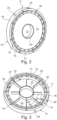
- Fig. 2:
- eine perspektivische Darstellung des scheibenförmigen Wärmetauschermoduls der Antriebs- und Getriebeeinheit aus
Figur 1 , und - Fig. 3:
- eine perspektivische, teilweise freigeschnittene Darstellung des scheibenförmigen Wärmetauschermoduls aus
Figur 2 , die das Innenleben der durchströmbaren Ringkammer und die daran angeordneten Turbulenzstege zeigt. - Wie
Figur 1 zeigt, kann eine Tunnelbohrmaschine 1 einen rotierend antreibbaren, Fräsrotor ähnlichen Bohrkopf 2 aufweisen, der von einem Antriebsmotor 3 her über eine Getriebeeinheit 4 rotierend angetrieben wird. Der genannte Bohrkopf 2 kann dabei beispielsweise über einen verzahnten Ring von der Getriebeeinheit 4 angetrieben werden, die in an sich bekannter Weise durch ein Bohrkopflager 5 abgestützt sein kann. - Wie
Figur 1 zeigt, kann die Getriebeeinheit 4 aus mehreren Getriebestufen aufgebaut sein, die hintereinander geschaltet sind, um die Antriebsdrehzahl des Antriebsmotors 3 in die gewünschte Rotordrehzahl des Bohrkopfs 2 zu übersetzen bzw. zu untersetzen, wobei beispielsweise drei Getriebestufen 4.1, 4.2 und 4.3 vorgesehen sein können. - Die genannten Getriebestufen können dabei Planetenstufen sein, die jeweils ein Sonnenrad 6, ein Hohlrad 7 und damit in Eingriff stehende Planetenräder 8 umfassen können, die auf einem Planetenträger 9 angeordnet sein können. Dabei können benachbarte Planetenstufen jeweils am Sonnenrad und am Steg des Planetenträgers miteinander verbunden sein, vgl.
Figur 1 . - Die genannten Getriebestufen 4.1, 4.2 und 4.3 können jeweils separat voneinander ausgebildet sein und jeweils zumindest näherungsweise zylindrische Getriebegehäuseteile aufweisen, mit denen sie aneinander setzbar sind, sodass die Getriebeeinheit 4 insgesamt modulartig aus den mehreren Getriebestufen aufgebaut ist, die axial hintereinander angeordnet und aneinander angeschlossen sind.
- Die erste Getriebestufe 4.1 kann mit dem Antriebsmotor 3 verbunden sein, wobei beispielsweise eine Motorabtriebswelle 10 mit dem Sonnenrad 4 der ersten Getriebestufe 4.1 drehfest gekoppelt sein kann. Die Abtriebswelle der letzten Getriebestufe 4.3, beispielsweise der Steg des Planetenträgers 9, kann mit der Antriebswelle des Bohrrotors 2 beispielsweise über einen verzahnten Ring gekoppelt sein.
- Wie
Figur 1 zeigt, kann zwischen zwei benachbarte Getriebestufen, insbesondere zwischen der relativ schnell drehenden ersten und zweiten Getriebestufen 4.1 und 4.2, ein Wärmetauschermodul 11 eingefügt sein, das sandwichartig zwischen den Stirnseiten der benachbarten Getriebestufen 4.1 und 4.2 eingepasst ist. Das genannte Wärmetauschermodul 11 kann dabei die Gehäuseteile der ersten und zweiten Getriebestufen 4.1 und 4.2 starr miteinander verbinden, beispielsweise mittels einer Schraubbolzenverbindung, die die beiden Gehäuseteile 12.1 und 12.2 gegen das Wärmetauschermodul 11 spannt. - Das genannte Wärmetauschermodul 11 ist in den
Figuren 2 und 3 näher gezeigt und kann insgesamt betrachtet scheibenförmig ausgebildet sein. Insbesondere kann das Wärmetauschermodul 11 einen Ringkorpus bilden, der eine Durchgangsausnehmung 13 in einem Mittelabschnitt aufweist und an gegenüberliegenden Stirnseiten jeweils einen Anschlussflansch 14 und 15 aufweist, die hinsichtlich Form und Abmessungen an die Anschlussflansche der beiden Getriebestufen 4.1 und 4.2 angepasst sind, sodass die genannten Getriebestufen 4.1 und 4.2 passgenau auf die beiden Anschlussflansche 14 und 15 des Wärmetauschermoduls 11 gesetzt und damit vorzugsweise spaltfrei, insbesondere flüssigkeitsdicht verbunden werden können. WieFigur 2 und 3 zeigen, können die genannten Anschlussflansche 14 und 15 beispielsweise jeweils eine ebene, ringförmige Stirnfläche 16 aufweisen, die sich näherungsweise zueinander parallel und/oder in Ebenen senkrecht zur Längsachse der Getriebeeinheit erstrecken können. Die genannten Stirnflächen 16 der Anschlussflansche 14 und 15 können an einem inneren Rand, gegebenenfalls aber auch in einem äußeren Rand, durch einen stirnseitig vorspringenden Ringsteg 17 begrenzt sein, welcher Ringsteg 17 sich in das Gehäuseteil 12.1 bzw. 12.2 des angrenzenden Getriebeabschnitts 4.1 und 4.2 hineinschieben und beispielsweise passgenau an der Innenumfangsfläche des jeweiligen Gehäuseteils anliegen kann. Durch den genannten Ringsteg 17 kann das Wärmetauschermodul 11 in radialer Richtung passgenau an den Gehäuseteilen 12.1 und 12.2 der benachbarten Getriebeabschnitte geführt sein. - Um die Getriebestufen 4.1 und 4.2 starr mit dem Wärmetauschermodul 11 verbinden zu können, können im Wärmetauschermodul 11 im Bereich des Anschlussflansches 14 und 15 Bohrungen 18 vorgesehen sein, um die beiden Gehäuseteile 12.1 und 12.2 mit dem Wärmetauschermodul 11 beispielsweise durch Schraubbolzen miteinander verbinden zu können. Die Schraubbolzen können sich durch die genannten Bohrungen 18 hindurch erstrecken.
- Wie
Figur 3 zeigt, kann das Wärmetauschermodul 11 vorteilhafterweise einen massiven, aus Vollmaterial gefertigten Außenring 19 umfassen, an dessen Stirnseiten die genannten Anschlussflansche 14 und 15 ausgebildet sein können. - Innerhalb des genannten Außenrings 19 kann das Wärmetauschermodul 11 einen Innenring 20 aufweisen, der die genannte Durchgangsausnehmung 13 des Wärmetauschermoduls 11 begrenzt. Die genannten Außen- und Innenringe 19, 20 können miteinander durch zwei plattenförmige Stirnwände 21, 22 miteinander verbunden sein, die zwischen sich und den genannten Innen- und Außenringen eine Ringkammer 23 begrenzen. Die genannten Stirnwände 21 und 22 können beispielsweise aus einem dünnen Metallblech oder einem anderen stark wärmeleitenden Material bestehen.
- Hiervon unabhängig können die genannten Stirnwände 21 und 22 zueinander parallel angeordnet und voneinander um ein Maß beabstandet sein, das näherungsweise der axialen Breite des Innenrings 20 und/oder des Außenrings 19 entspricht.
- Die genannten Stirnwände 21 und 22 können im Wesentlichen eben ausgebildet sein, insbesondere zwei ebene Ringscheiben bilden.
- Die genannten Stirnwände 21 und 22 sind mit den Außen- und Innenringen 19, 20 flüssigkeitsdicht verbunden, beispielsweise verschweißt und/oder verklebt.
- Um Temperierflüssigkeit durch die Ringkammer 23 zirkulieren zu können, besitzt die genannte Ringkammer 23 einen Zulauf 24 und einen Ablauf 25, die sich vorteilhafterweise durch den Außenring 19 hindurch erstrecken können und vorteilhafterweise am Außenumfang des genannten Außenrings 19 münden können.
- Wie
Figur 2 zeigt, können Zulauf 24 und Ablauf 25 vorteilhafterweise zueinander benachbart und/oder im selben Sektor des Außenrings 19 angeordnet sein, insbesondere auf einer Oberseite des Wärmetauschermoduls 11, wenn dieses bestimmungsgemäß in die Getriebeeinheit 4 integriert ist. - Zusätzlich zu den genannten Zu- und Abläufen 24 und 25 kann an der Unterseite der Ringkammer 23 ein oder mehrere weitere Abläufe 26 vorgesehen sein, um die Kühlflüssigkeit aus der Ringkammer 23 ablassen zu können, wobei sich diese Abläufe 26 vorteilhafterweise auch durch den Außenring 19 hindurch erstrecken können, vgl.
Figur 3 . - Um sicherzustellen, dass die Temperierflüssigkeit die gesamte Ringkammer 23 durchströmt, kann in der Ringkammer 23 zwischen den an der Oberseite vorgesehenen Zulauf 24 und Ablauf 25 ein Trennsteg 27 vorgesehen sein, der die Ringkammer 23 zwischen Zulauf 24 und Ablauf 25 nach Art eines Schlitzrings unterteilt. Der genannte Trennsteg 27 kann flüssigkeitsdicht sowohl mit dem Außenring 19 und dem Innenring 20 als auch mit den beiden voneinander beabstandeten Stirnwänden 21 und 22 verbunden sein.
- Der Zulauf 24 mündet somit auf der einen Seite des Trennstegs 27 in die Ringkammer 23, während der Ablauf 25 auf der gegenüberliegenden Seite des Trennstegs 27 in die Ringkammer 23 mündet.
- Um die Temperierflüssigkeit beim Durchströmen der Ringkammer 23 in alle Bereiche der Ringkammer 23 zu leiten, können in der Ringkammer 23 ferner Turbulenzstege 28 vorgesehen sein, die derart angeordnet und ausgebildet sein können, dass das die Ringkammer 23 umlaufend durchströmende Fluid zwischen dem Innenring 20 und dem Außenring 19 hin und her mäandert bzw. entlang der Umlaufrichtung schlangenförmig hin und her strömt. Die genannten Turbulenzstege 28 können abwechselnd radial zueinander versetzt angeordnet sein und abwechselnd einen Spalt zum Innenring 20 und einen Spalt zum Außenring 19 zum Hindurchtreten der Temperierflüssigkeit belassen.
- Unabhängig hiervon können sich die genannten Turbulenzstege 28 zwischen den beiden Stirnwänden 21 und 22 erstrecken und diese miteinander verbinden, wobei sich die genannten Turbulenzstege 28 zumindest näherungsweise in radialer Richtung oder von innen nach außen, das heißt in Richtung vom Innenring zum Außenring oder umgekehrt erstrecken können.
- Insbesondere können die genannten Turbulenzstege 28 abwechselnd einmal an den Innenring 20 anschließen und einmal an den Außenring 19 anschließen und zum jeweils anderen Ring einen Spalt 29 belassen, durch den die Temperaturflüssigkeit hindurchströmen kann. Die genannten Spalte 29 liegen dabei abwechselnd am Außenring 19 und am Innenring 20, vgl.
Figur 3 . - Das beschriebene Wärmetauschermodul 11 besitzt signifikante Vorteile. Zum einen ist dies eine kostengünstige und sehr robuste Struktur, die auch für harte Einsatzbedingungen wie beispielsweise bei einer Tunnelbohrmaschine geeignet ist, wobei insbesondere der massive Außenring auch die Stoßbelastungen erträgt, wie sie bei Tunnelbohrmaschinen auftreten.
- Dabei macht nicht nur der massive Außenring 19, sondern auch die Kastenbauweise, gemäß der die Stirnwände 21 und 22 durch die Außen- und Innenringe sowie die Turbulenzstege mehrfach miteinander verbunden sind, die Struktur sehr stabil, sodass auch bei starken Vibrationen, Druckspitzen oder anderen äußeren Einflüssen keine Beschädigungen auftreten. Das Wärmetauschermodul ist dabei direkt in die Getriebeeinheit 4 integriert und auch hierdurch vor äußeren Einflüssen zusätzlich geschützt.
- Die Anordnung des Wärmetauschermoduls 11 zwischen den ersten beiden Getriebestufen 4.1 und 4.2 bewirkt zudem hervorragende Anströmverhältnisse, wobei eine doppelte Wirkfläche durch die beiden mit dem Getriebeschmierstoff beider Getriebestufen in Kontakt stehenden Stirnwände 21 und 22 entsteht. Die Verlustleistung wird in unmittelbarer Nähe vom Entstehungsort aufgenommen. Besonders in den ersten schnelldrehenden Getriebestufen 4.1 und 4.2 sind die Verlustleistungen und damit die entstehende Wärme am größten.
- Durch die radiale, versetzte Anordnung der Turbulenzbleche bzw. -stege 28 wird das ringförmig um die Durchgangsausnehmung 13 umlaufende Temperierfluid mehrere Male umgelenkt, was für eine ganzheitliche Umströmung und maximale Ausnutzung der Wärmeübertragungsfläche durch eine turbulente Strömung in Abhängigkeit der Durchflussmenge sorgt.
- Das Wärmetauschermodul 11 ist einfach an bestehende Getriebekonstruktionen zu adaptieren. Dabei kann das Wärmetauschermodul 11 bei Bedarf einfach zwischen den Planetenstufen der Getriebeeinheit 4 platziert werden.
- Durch die modulare Ausbildung können auch mehrere Wärmetauschermodule 11 in Reihe hintereinander geschaltet werden und damit die Kühlleistung nahezu beliebig gesteigert werden.
- Die axialen Durchgangsbohrungen 30 bzw. -ausnehmungen, die in axialer Richtung durch das Wärmetauschermodul 11 hindurchführen, erlauben auf Höhe der Hohlräder 7 der Planetengetriebestufen aus den dortigen Zahnflanken verdrängtem Öl durch die Durchgangsausnehmungen 30 hindurch zu strömen und eine direkte Kühlwirkung zu erfahren. Die genannten Durchgangsausnehmungen 30 fördern zudem den Ölaustausch bzw. Schmiermittelaustausch in der Getriebeeinheit 4 und sorgen für eine gleichmäßige Durchmischung des Schmierstoffs.
Claims (10)
- Temperiervorrichtung zum Kühlen und/oder Beheizen eines Tunnelbohrer-Getriebes (4), mit zumindest einem Wärmetauschermodul (11), das einen Flüssigkeitsmantel (31) aufweist und einen Ringkorpus zum sandwichartigen Einpassen zwischen zwei benachbarte Antriebs- und/oder Getriebeabschnitte (4.1, 4.2) bildet, welcher Ringkorpus eine zentrale Durchgangsausnehmung (13) zum Hindurchtreten eines drehbaren Antriebs- und/oder Getriebeelements (32) aufweist, sowie an gegenüberliegenden Stirnseiten jeweils einen Anschlussflansch (14, 15) zum passgenauen stirnseitigen Anschließen an zwei benachbarte Getriebe- und/oder Antriebsabschnitte (4.1, 4.2) besitzt, wobei der Flüssigkeitsmantel (31) eine Ringkammer (23) im Inneren des Ringkorpus bildet, die um die Durchgangsausnehmung (13) herum verläuft, wobei in der Ringkammer (23) Turbulenzstege (28) vorgesehen sind, dadurch gekennzeichnet, dass- die Turbulenzstege (28) radial zueinander versetzt sind und abwechselnd vom Innenumfang der Ringkammer (23) nach Außen und vom Außenumfang der Ringkammer (23) nach Innen vorspringen und abwechselnd am Innenumfang und am Außenumfang der Ringkammer (23) einen Durchtrittsspalt (29) für das zu zirkulierende Temperierfluid begrenzen, sodass ein mäanderförmiger Strömungspfad hin- und hergehend vom Innenumfang zum Außenumfang der Ringkammer verläuft, und/oder- die Turbulenzstege (28) jeweils einen weiteren Durchtrittsspalt zu einer von zwei Stirnwänden (21, 22), die die Ringkammer (23) stirnseitig begrenzen, belassen, wobei die Turbulenzstege (28) abwechselnd an die eine Stirnwand (21) und die andere Stirnwand (22) anschließen, sodass ein mäanderförmiger Strömungspfad hin- und hergehend von der einen Stirnwand (21) zur anderen Stirnwand (22) verläuft.
- Temperiervorrichtung nach dem vorhergehenden Anspruch, wobei die Ringkammer zumindest einen Zulauf (24) und zumindest einen Ablauf (25) besitzt, die zueinander benachbart und/oder in einem Sektor der Ringkammer (23) angeordnet und durch einen Trennsteg (27) voneinander getrennt sind, welcher Trennsteg die Ringkammer (23) in Umfangsrichtung nach Art eines Schlitzrings in zwei Ringkammerabschnitte unterteilt.
- Temperiervorrichtung nach dem vorhergehenden Anspruch, wobei der Zulauf (24) und der Ablauf (25) an der Oberseite des Wärmetauschermoduls (11) angeordnet sind.
- Temperiervorrichtung nach einem der vorhergehenden Ansprüche, wobei der Ringkorpus des Wärmetauschermoduls (11) einen massiven Außenring (19), an dem die beiden gegenüberliegenden Anschlussflansche (14, 15) ausgebildet sind, einen innerhalb des Außenrings (19) angeordneten Innenring (20) sowie zwei vorzugsweise ebene, plattenförmige Stirnwände (21, 22) aufweist, die die Außen- und Innenringe (19, 20) miteinander verbinden und zwischen sich den Flüssigkeitsmantel (21) begrenzen.
- Temperiervorrichtung nach dem vorhergehenden Anspruch, wobei die Stirnwände (21, 22) eine kleinere Wandstärke als der Außenring (19) besitzen, wobei eine Wandstärke der Stirnwände (21, 22) vorzugsweise weniger als ein Drittel oder weniger als ein Viertel der Wandstärke des Außenrings (19) beträgt.
- Temperiervorrichtung nach einem der beiden vorhergehenden Ansprüche, wobei der Außenring (19) innerhalb der Anschlussflansche (14, 15) axiale Durchgangsausnehmungen (30) zum Strömungsverbinden der beiden Getriebe- und/oder Antriebsabschnitte (4.1, 4.2), zwischen denen das Wärmetauschermodul (11) sandwichartig angeordnet ist, aufweist.
- Getriebe- und/oder Antriebseinheit umfassend zumindest zwei Getriebe- und/oder Antriebsabschnitte (4.1, 4.2), zwischen denen eine Temperiervorrichtung, die gemäß einem der vorhergehenden Ansprüche ausgebildet ist, angeordnet ist, wobei die zwei genannten Getriebe- und/oder Antriebsabschnitte (4.1, 4.2) an den gegenüberliegenden Anschlussflanschen (14, 15) des Wärmetauschermoduls (11) befestigt und durch das Wärmetauschermodul (11) miteinander verbunden sind, wobei sich ein Getriebe- und/oder Antriebselement (32), das die zwei genannten Getriebe- und/oder Antriebsabschnitte (4.1, 4.2) kraft- und/oder drehmomentübertragend miteinander verbindet, durch die Durchgangsausnehmung (13) in dem Wärmetauschermodul (11) hindurch erstreckt.
- Getriebe- und/oder Antriebseinheit nach dem vorhergehenden Anspruch, wobei die zwei an das Wärmetauschermodul (11) angeschlossenen Getriebeabschnitte jeweils eine Planetengetriebestufe umfassen, wobei das sich durch die Durchgangsausnehmung (13) des Wärmetauschermoduls (11) hindurch erstreckende Antriebselement ein Sonnenrad (6) der einen Planetengetriebestufe mit dem Planetenträger (9) der anderen Planetengetriebestufe drehfest verbindet.
- Getriebe- und/oder Antriebseinheit nach einem der beiden vorhergehenden Ansprüche, wobei das zumindest eine Wärmetauschermodul (11) zwischen einer ersten und einer zweiten Getriebestufe angeordnet ist, welche ersten und zweiten Getriebestufen hintereinander geschaltet an einen Antriebsmotor (3) anschließen und/oder die beiden Getriebestufen mit den höchsten Drehzahlen sind.
- Tunnelbohrmaschine mit einem Bohrkopf (2), der von einem Antriebsmotor (3) über eine Getriebeeinheit (4) antreibbar ist, wobei in die Getriebeeinheit (4) eine Temperiervorrichtung, die gemäß einem der Ansprüche 1 bis 10 ausgebildet ist, integriert ist.
Applications Claiming Priority (3)
| Application Number | Priority Date | Filing Date | Title |
|---|---|---|---|
| DE202019101298 | 2019-03-08 | ||
| DE202019101918.2U DE202019101918U1 (de) | 2019-03-08 | 2019-04-03 | Temperiervorrichtung für Antriebs- und/oder Getriebeeinheiten wie Tunnelbohrer-Getriebe |
| PCT/EP2020/055024 WO2020182469A1 (de) | 2019-03-08 | 2020-02-26 | Temperiervorrichtung für antriebs- und/oder getriebeeinheiten wie tunnelbohrer-getriebe |
Publications (2)
| Publication Number | Publication Date |
|---|---|
| EP3906369A1 EP3906369A1 (de) | 2021-11-10 |
| EP3906369B1 true EP3906369B1 (de) | 2023-04-05 |
Family
ID=71131968
Family Applications (1)
| Application Number | Title | Priority Date | Filing Date |
|---|---|---|---|
| EP20710433.2A Active EP3906369B1 (de) | 2019-03-08 | 2020-02-26 | Temperiervorrichtung für antriebs- und/oder getriebeeinheiten wie tunnelbohrer-getriebe |
Country Status (6)
| Country | Link |
|---|---|
| US (1) | US11821508B2 (de) |
| EP (1) | EP3906369B1 (de) |
| CN (1) | CN113557377B (de) |
| DE (1) | DE202019101918U1 (de) |
| ES (1) | ES2946157T3 (de) |
| WO (1) | WO2020182469A1 (de) |
Families Citing this family (6)
| Publication number | Priority date | Publication date | Assignee | Title |
|---|---|---|---|---|
| DE202019101918U1 (de) | 2019-03-08 | 2020-06-09 | Liebherr-Components Biberach Gmbh | Temperiervorrichtung für Antriebs- und/oder Getriebeeinheiten wie Tunnelbohrer-Getriebe |
| DE102020210019A1 (de) | 2020-08-07 | 2021-08-05 | Zf Friedrichshafen Ag | Wasserkammer mit Spiralführung |
| EP4318898B1 (de) * | 2021-03-30 | 2025-11-05 | Aisin Corporation | Fahrzeugsantriebsvorrichtung |
| DE102022117537A1 (de) | 2022-07-13 | 2024-01-18 | Liebherr-Components Biberach Gmbh | Bau- und/oder Flurfördermaschine sowie Antriebseinheit hierfür |
| CN117117670B (zh) * | 2023-07-17 | 2024-08-13 | 中铁四局集团有限公司 | 一种隧道供电系统 |
| CN116667586B (zh) * | 2023-08-01 | 2024-06-04 | 昆明祥楠科技有限公司 | 一种多轴输出的可调节减速电机 |
Citations (2)
| Publication number | Priority date | Publication date | Assignee | Title |
|---|---|---|---|---|
| CN101793149A (zh) | 2010-03-22 | 2010-08-04 | 三一重型装备有限公司 | 一种减速机及包括该减速机的掘进机 |
| EP2645543A1 (de) | 2010-11-22 | 2013-10-02 | Kobelco Construction Machinery Co., Ltd. | Antriebsvorrichtung und baumaschine damit |
Family Cites Families (24)
| Publication number | Priority date | Publication date | Assignee | Title |
|---|---|---|---|---|
| US3362162A (en) * | 1965-07-02 | 1968-01-09 | Rover Co Ltd | Automatic power transmissions for motor vehicles |
| DE2551934C2 (de) * | 1975-11-19 | 1977-12-15 | Friedrich Deckel AG, 8000 München | Mehrstufiges Zahnrad-Schaltgetriebe |
| US5498084A (en) * | 1994-12-14 | 1996-03-12 | Quadion Corporation | Automatic transmission front-bearing oil-flow control and method of controlling same |
| JP3750209B2 (ja) * | 1996-03-29 | 2006-03-01 | 株式会社デンソー | 沸騰冷却装置 |
| US6257368B1 (en) * | 1999-09-27 | 2001-07-10 | Reliance Electric Technologies, Llc | Rotating shaft assembly |
| DE10149704A1 (de) * | 2001-10-09 | 2003-04-10 | Zf Sachs Ag | Eingangsseitig zentral an einer Drehwelle oder Drehkomponente angebundene Kupplungseinrichtung in einem Kraftfahrzeug-Antriebsstrang |
| DE202007003577U1 (de) * | 2006-12-01 | 2008-04-10 | Liebherr-Hausgeräte Ochsenhausen GmbH | Kühl- und/oder Gefriergerät |
| DE102007049599A1 (de) * | 2007-10-15 | 2009-05-07 | Innovative Windpower Ag | Temperaturregelung von aneinandergekoppeltem Getriebe und Generator bei einer Windenergieanlage |
| CN101285519A (zh) * | 2008-06-02 | 2008-10-15 | 唐君源 | 一种防爆型式摩擦片控制的软启动减速机 |
| EP2310707B1 (de) * | 2008-07-14 | 2012-12-05 | Schaeffler Technologies AG & Co. KG | Doppelkupplung |
| JP2011196530A (ja) * | 2010-03-23 | 2011-10-06 | Daihatsu Motor Co Ltd | 変速機の潤滑油循環構造 |
| JP5315279B2 (ja) * | 2010-03-31 | 2013-10-16 | 株式会社小松製作所 | 減速機及び旋回装置 |
| DE102011007254A1 (de) * | 2011-04-13 | 2012-10-18 | Schaeffler Technologies AG & Co. KG | Antriebsvorrichtung, insbesondere für ein Fahrzeug |
| JP6158526B2 (ja) * | 2013-02-14 | 2017-07-05 | 住友重機械工業株式会社 | ショベル |
| WO2014069536A1 (ja) * | 2012-11-05 | 2014-05-08 | 住友重機械工業株式会社 | ショベル |
| JP2016166639A (ja) * | 2015-03-09 | 2016-09-15 | Ntn株式会社 | サイクロイド減速機およびこれを備えたモータ駆動装置 |
| CN104930173B (zh) * | 2015-07-02 | 2017-05-24 | 中车戚墅堰机车车辆工艺研究所有限公司 | 风机增速箱及其花键副的润滑冷却冲洗结构 |
| DE102015214334A1 (de) * | 2015-07-29 | 2017-02-02 | Volkswagen Aktiengesellschaft | Antriebsanordnung für ein Kraftfahrzeug |
| DE102015214330A1 (de) | 2015-07-29 | 2017-02-02 | Schaeffler Technologies AG & Co. KG | Großwälzlager |
| DE102016208201A1 (de) * | 2016-05-12 | 2017-11-16 | Zf Friedrichshafen Ag | Getriebe für Tunnelbohrmaschine mit schaltbar überlagerter Planetenstufe |
| DE202018104476U1 (de) * | 2018-08-03 | 2018-08-13 | Chuan-Shan Huang | Kühlvorrichtung für Pfahltreiber |
| CN109114210A (zh) * | 2018-11-09 | 2019-01-01 | 湖北正信齿轮制造股份有限公司 | 一种工作腔内附加循环冷却流道的取力器 |
| DE202019101918U1 (de) | 2019-03-08 | 2020-06-09 | Liebherr-Components Biberach Gmbh | Temperiervorrichtung für Antriebs- und/oder Getriebeeinheiten wie Tunnelbohrer-Getriebe |
| CN113357354B (zh) * | 2021-07-08 | 2022-01-25 | 湖南南方宇航高精传动有限公司 | 一种封闭式带导向螺旋板的循环冷却装置 |
-
2019
- 2019-04-03 DE DE202019101918.2U patent/DE202019101918U1/de active Active
-
2020
- 2020-02-26 ES ES20710433T patent/ES2946157T3/es active Active
- 2020-02-26 CN CN202080019382.6A patent/CN113557377B/zh active Active
- 2020-02-26 WO PCT/EP2020/055024 patent/WO2020182469A1/de not_active Ceased
- 2020-02-26 EP EP20710433.2A patent/EP3906369B1/de active Active
-
2021
- 2021-09-08 US US17/447,125 patent/US11821508B2/en active Active
Patent Citations (2)
| Publication number | Priority date | Publication date | Assignee | Title |
|---|---|---|---|---|
| CN101793149A (zh) | 2010-03-22 | 2010-08-04 | 三一重型装备有限公司 | 一种减速机及包括该减速机的掘进机 |
| EP2645543A1 (de) | 2010-11-22 | 2013-10-02 | Kobelco Construction Machinery Co., Ltd. | Antriebsvorrichtung und baumaschine damit |
Non-Patent Citations (2)
| Title |
|---|
| "Produktbereich Getriebetechnik Katalog", 1 November 2002, REXROTH BOSCH GROUP, article ANONYMOUS: "Rexroth REDULUS-Getriebe für Tunnelvortriebsmaschinen", pages: R06 - R07, XP093153332 |
| ANONYMOUS: "Pushing the limits", CONSTRUCTION BRIEFING, 20 March 2008 (2008-03-20), pages 1 - 7, XP093153242, Retrieved from the Internet <URL:https://www.constructionbriefing.com/news/pushing-the-limits/1008390.article> |
Also Published As
| Publication number | Publication date |
|---|---|
| ES2946157T3 (es) | 2023-07-13 |
| EP3906369A1 (de) | 2021-11-10 |
| WO2020182469A1 (de) | 2020-09-17 |
| US11821508B2 (en) | 2023-11-21 |
| DE202019101918U1 (de) | 2020-06-09 |
| US20210396137A1 (en) | 2021-12-23 |
| CN113557377A (zh) | 2021-10-26 |
| CN113557377B (zh) | 2023-12-12 |
Similar Documents
| Publication | Publication Date | Title |
|---|---|---|
| EP3906369B1 (de) | Temperiervorrichtung für antriebs- und/oder getriebeeinheiten wie tunnelbohrer-getriebe | |
| DE102011056007B4 (de) | Kühlsystem für eine rotierende elektrische Maschine höchster Leistungsdichte | |
| DE10350935B4 (de) | Drehmomentwandler | |
| EP2537235B1 (de) | Elektrische antriebseinheit | |
| DE102009029716B4 (de) | Elektromotor | |
| DE102014103363A1 (de) | Antriebsmodul mit sprühkühlung eines elektromotors | |
| EP0858692B1 (de) | Flüssigkeitskühlung für elektrische maschinen | |
| DE102015011863B4 (de) | Elektrische Maschine | |
| EP2479875B1 (de) | Flüssigkeitsgekühltes Gehäuse mit Lagerschild für elektrische Maschine | |
| DE112018006046T5 (de) | Dualfunktionelles achsenwärmemanagementsystem | |
| DE2750519A1 (de) | Fluessigkeitskupplung | |
| DE102019205762A1 (de) | Elektrische Maschine mit Drehmomentabstützung im Gehäuse | |
| DE102011076140A1 (de) | Kühlmantel für Elektromotor | |
| EP1364133A1 (de) | Vollgefüllte nasslaufkupplung mit hydrodynamischer kühlung | |
| DE2944008A1 (de) | Kupplungsbremseinheit | |
| DE102019207312A1 (de) | Kühlanordnung für ein wärmeerzeugendes rotierendes Bauteil einer elektrischen Maschine sowie elektrische Maschine | |
| EP2394091B1 (de) | Tragelement mit einer antriebseinheit | |
| EP2020735A2 (de) | Unterwassermotor mit Wärmetauscher | |
| DE102020115905A1 (de) | Stator für eine elektrische Maschine zum Antrieb eines Kraftfahrzeugs | |
| DE29913314U1 (de) | Elektrische Maschine | |
| EP4244041B1 (de) | Multiwellen-aufbereitungseinheit für kunststoffschmelzen | |
| DE112023005702T5 (de) | Elektrische Maschine mit Ölkühlung | |
| EP3799264B1 (de) | Antriebswelle einer dynamoelektrischen maschine | |
| DE2123481C3 (de) | Am drehenden Kupplungsgehäuse einer hydrodynamischen Kupplung befestigter Zahnradring für den Antrieb eines Zahnradgetriebes | |
| EP4333267A1 (de) | Modulare rotorwelle mit integrierten kühlkanälen |
Legal Events
| Date | Code | Title | Description |
|---|---|---|---|
| STAA | Information on the status of an ep patent application or granted ep patent |
Free format text: STATUS: UNKNOWN |
|
| STAA | Information on the status of an ep patent application or granted ep patent |
Free format text: STATUS: THE INTERNATIONAL PUBLICATION HAS BEEN MADE |
|
| PUAI | Public reference made under article 153(3) epc to a published international application that has entered the european phase |
Free format text: ORIGINAL CODE: 0009012 |
|
| STAA | Information on the status of an ep patent application or granted ep patent |
Free format text: STATUS: REQUEST FOR EXAMINATION WAS MADE |
|
| 17P | Request for examination filed |
Effective date: 20210805 |
|
| AK | Designated contracting states |
Kind code of ref document: A1 Designated state(s): AL AT BE BG CH CY CZ DE DK EE ES FI FR GB GR HR HU IE IS IT LI LT LU LV MC MK MT NL NO PL PT RO RS SE SI SK SM TR |
|
| RIN1 | Information on inventor provided before grant (corrected) |
Inventor name: BULLIG, JOHANNES Inventor name: FREUDE, PHILIPP |
|
| DAV | Request for validation of the european patent (deleted) | ||
| DAX | Request for extension of the european patent (deleted) | ||
| REG | Reference to a national code |
Ref legal event code: R079 Ipc: E21D0009100000 Ref country code: DE Ref legal event code: R079 Ref document number: 502020002931 Country of ref document: DE Free format text: PREVIOUS MAIN CLASS: F16H0057040000 Ipc: E21D0009100000 |
|
| GRAP | Despatch of communication of intention to grant a patent |
Free format text: ORIGINAL CODE: EPIDOSNIGR1 |
|
| STAA | Information on the status of an ep patent application or granted ep patent |
Free format text: STATUS: GRANT OF PATENT IS INTENDED |
|
| RIC1 | Information provided on ipc code assigned before grant |
Ipc: F16H 57/04 20100101ALI20220929BHEP Ipc: F16H 1/46 20060101ALI20220929BHEP Ipc: F16H 57/08 20060101ALI20220929BHEP Ipc: F01M 5/00 20060101ALI20220929BHEP Ipc: E21D 9/10 20060101AFI20220929BHEP |
|
| INTG | Intention to grant announced |
Effective date: 20221026 |
|
| GRAS | Grant fee paid |
Free format text: ORIGINAL CODE: EPIDOSNIGR3 |
|
| GRAA | (expected) grant |
Free format text: ORIGINAL CODE: 0009210 |
|
| STAA | Information on the status of an ep patent application or granted ep patent |
Free format text: STATUS: THE PATENT HAS BEEN GRANTED |
|
| RIN1 | Information on inventor provided before grant (corrected) |
Inventor name: BULLIG, JOHANNES Inventor name: FREUDE, PHILIPP |
|
| AK | Designated contracting states |
Kind code of ref document: B1 Designated state(s): AL AT BE BG CH CY CZ DE DK EE ES FI FR GB GR HR HU IE IS IT LI LT LU LV MC MK MT NL NO PL PT RO RS SE SI SK SM TR |
|
| REG | Reference to a national code |
Ref country code: GB Ref legal event code: FG4D Free format text: NOT ENGLISH |
|
| REG | Reference to a national code |
Ref country code: DE Ref legal event code: R096 Ref document number: 502020002931 Country of ref document: DE |
|
| REG | Reference to a national code |
Ref country code: CH Ref legal event code: EP |
|
| REG | Reference to a national code |
Ref country code: AT Ref legal event code: REF Ref document number: 1558382 Country of ref document: AT Kind code of ref document: T Effective date: 20230415 |
|
| REG | Reference to a national code |
Ref country code: NL Ref legal event code: FP |
|
| REG | Reference to a national code |
Ref country code: IE Ref legal event code: FG4D Free format text: LANGUAGE OF EP DOCUMENT: GERMAN |
|
| REG | Reference to a national code |
Ref country code: NO Ref legal event code: T2 Effective date: 20230405 |
|
| REG | Reference to a national code |
Ref country code: ES Ref legal event code: FG2A Ref document number: 2946157 Country of ref document: ES Kind code of ref document: T3 Effective date: 20230713 |
|
| REG | Reference to a national code |
Ref country code: LT Ref legal event code: MG9D |
|
| P01 | Opt-out of the competence of the unified patent court (upc) registered |
Effective date: 20230630 |
|
| PG25 | Lapsed in a contracting state [announced via postgrant information from national office to epo] |
Ref country code: SE Free format text: LAPSE BECAUSE OF FAILURE TO SUBMIT A TRANSLATION OF THE DESCRIPTION OR TO PAY THE FEE WITHIN THE PRESCRIBED TIME-LIMIT Effective date: 20230405 Ref country code: PT Free format text: LAPSE BECAUSE OF FAILURE TO SUBMIT A TRANSLATION OF THE DESCRIPTION OR TO PAY THE FEE WITHIN THE PRESCRIBED TIME-LIMIT Effective date: 20230807 |
|
| PG25 | Lapsed in a contracting state [announced via postgrant information from national office to epo] |
Ref country code: RS Free format text: LAPSE BECAUSE OF FAILURE TO SUBMIT A TRANSLATION OF THE DESCRIPTION OR TO PAY THE FEE WITHIN THE PRESCRIBED TIME-LIMIT Effective date: 20230405 Ref country code: PL Free format text: LAPSE BECAUSE OF FAILURE TO SUBMIT A TRANSLATION OF THE DESCRIPTION OR TO PAY THE FEE WITHIN THE PRESCRIBED TIME-LIMIT Effective date: 20230405 Ref country code: LV Free format text: LAPSE BECAUSE OF FAILURE TO SUBMIT A TRANSLATION OF THE DESCRIPTION OR TO PAY THE FEE WITHIN THE PRESCRIBED TIME-LIMIT Effective date: 20230405 Ref country code: LT Free format text: LAPSE BECAUSE OF FAILURE TO SUBMIT A TRANSLATION OF THE DESCRIPTION OR TO PAY THE FEE WITHIN THE PRESCRIBED TIME-LIMIT Effective date: 20230405 Ref country code: IS Free format text: LAPSE BECAUSE OF FAILURE TO SUBMIT A TRANSLATION OF THE DESCRIPTION OR TO PAY THE FEE WITHIN THE PRESCRIBED TIME-LIMIT Effective date: 20230805 Ref country code: HR Free format text: LAPSE BECAUSE OF FAILURE TO SUBMIT A TRANSLATION OF THE DESCRIPTION OR TO PAY THE FEE WITHIN THE PRESCRIBED TIME-LIMIT Effective date: 20230405 Ref country code: GR Free format text: LAPSE BECAUSE OF FAILURE TO SUBMIT A TRANSLATION OF THE DESCRIPTION OR TO PAY THE FEE WITHIN THE PRESCRIBED TIME-LIMIT Effective date: 20230706 |
|
| PG25 | Lapsed in a contracting state [announced via postgrant information from national office to epo] |
Ref country code: FI Free format text: LAPSE BECAUSE OF FAILURE TO SUBMIT A TRANSLATION OF THE DESCRIPTION OR TO PAY THE FEE WITHIN THE PRESCRIBED TIME-LIMIT Effective date: 20230405 |
|
| REG | Reference to a national code |
Ref country code: DE Ref legal event code: R026 Ref document number: 502020002931 Country of ref document: DE |
|
| PLBI | Opposition filed |
Free format text: ORIGINAL CODE: 0009260 |
|
| PG25 | Lapsed in a contracting state [announced via postgrant information from national office to epo] |
Ref country code: SK Free format text: LAPSE BECAUSE OF FAILURE TO SUBMIT A TRANSLATION OF THE DESCRIPTION OR TO PAY THE FEE WITHIN THE PRESCRIBED TIME-LIMIT Effective date: 20230405 |
|
| PLAX | Notice of opposition and request to file observation + time limit sent |
Free format text: ORIGINAL CODE: EPIDOSNOBS2 |
|
| PG25 | Lapsed in a contracting state [announced via postgrant information from national office to epo] |
Ref country code: SM Free format text: LAPSE BECAUSE OF FAILURE TO SUBMIT A TRANSLATION OF THE DESCRIPTION OR TO PAY THE FEE WITHIN THE PRESCRIBED TIME-LIMIT Effective date: 20230405 Ref country code: SK Free format text: LAPSE BECAUSE OF FAILURE TO SUBMIT A TRANSLATION OF THE DESCRIPTION OR TO PAY THE FEE WITHIN THE PRESCRIBED TIME-LIMIT Effective date: 20230405 Ref country code: RO Free format text: LAPSE BECAUSE OF FAILURE TO SUBMIT A TRANSLATION OF THE DESCRIPTION OR TO PAY THE FEE WITHIN THE PRESCRIBED TIME-LIMIT Effective date: 20230405 Ref country code: EE Free format text: LAPSE BECAUSE OF FAILURE TO SUBMIT A TRANSLATION OF THE DESCRIPTION OR TO PAY THE FEE WITHIN THE PRESCRIBED TIME-LIMIT Effective date: 20230405 Ref country code: DK Free format text: LAPSE BECAUSE OF FAILURE TO SUBMIT A TRANSLATION OF THE DESCRIPTION OR TO PAY THE FEE WITHIN THE PRESCRIBED TIME-LIMIT Effective date: 20230405 Ref country code: CZ Free format text: LAPSE BECAUSE OF FAILURE TO SUBMIT A TRANSLATION OF THE DESCRIPTION OR TO PAY THE FEE WITHIN THE PRESCRIBED TIME-LIMIT Effective date: 20230405 |
|
| 26 | Opposition filed |
Opponent name: ZF FRIEDRICHSHAFEN AG Effective date: 20240105 |
|
| PG25 | Lapsed in a contracting state [announced via postgrant information from national office to epo] |
Ref country code: SI Free format text: LAPSE BECAUSE OF FAILURE TO SUBMIT A TRANSLATION OF THE DESCRIPTION OR TO PAY THE FEE WITHIN THE PRESCRIBED TIME-LIMIT Effective date: 20230405 |
|
| PLBB | Reply of patent proprietor to notice(s) of opposition received |
Free format text: ORIGINAL CODE: EPIDOSNOBS3 |
|
| PG25 | Lapsed in a contracting state [announced via postgrant information from national office to epo] |
Ref country code: SI Free format text: LAPSE BECAUSE OF FAILURE TO SUBMIT A TRANSLATION OF THE DESCRIPTION OR TO PAY THE FEE WITHIN THE PRESCRIBED TIME-LIMIT Effective date: 20230405 |
|
| PG25 | Lapsed in a contracting state [announced via postgrant information from national office to epo] |
Ref country code: MC Free format text: LAPSE BECAUSE OF FAILURE TO SUBMIT A TRANSLATION OF THE DESCRIPTION OR TO PAY THE FEE WITHIN THE PRESCRIBED TIME-LIMIT Effective date: 20230405 |
|
| REG | Reference to a national code |
Ref country code: CH Ref legal event code: PL |
|
| PG25 | Lapsed in a contracting state [announced via postgrant information from national office to epo] |
Ref country code: LU Free format text: LAPSE BECAUSE OF NON-PAYMENT OF DUE FEES Effective date: 20240226 |
|
| PG25 | Lapsed in a contracting state [announced via postgrant information from national office to epo] |
Ref country code: CH Free format text: LAPSE BECAUSE OF NON-PAYMENT OF DUE FEES Effective date: 20240229 |
|
| PG25 | Lapsed in a contracting state [announced via postgrant information from national office to epo] |
Ref country code: LU Free format text: LAPSE BECAUSE OF NON-PAYMENT OF DUE FEES Effective date: 20240226 Ref country code: CH Free format text: LAPSE BECAUSE OF NON-PAYMENT OF DUE FEES Effective date: 20240229 |
|
| PG25 | Lapsed in a contracting state [announced via postgrant information from national office to epo] |
Ref country code: BG Free format text: LAPSE BECAUSE OF FAILURE TO SUBMIT A TRANSLATION OF THE DESCRIPTION OR TO PAY THE FEE WITHIN THE PRESCRIBED TIME-LIMIT Effective date: 20230405 |
|
| PG25 | Lapsed in a contracting state [announced via postgrant information from national office to epo] |
Ref country code: BG Free format text: LAPSE BECAUSE OF FAILURE TO SUBMIT A TRANSLATION OF THE DESCRIPTION OR TO PAY THE FEE WITHIN THE PRESCRIBED TIME-LIMIT Effective date: 20230405 |
|
| REG | Reference to a national code |
Ref country code: BE Ref legal event code: MM Effective date: 20240229 |
|
| PG25 | Lapsed in a contracting state [announced via postgrant information from national office to epo] |
Ref country code: BE Free format text: LAPSE BECAUSE OF NON-PAYMENT OF DUE FEES Effective date: 20240229 |
|
| PG25 | Lapsed in a contracting state [announced via postgrant information from national office to epo] |
Ref country code: IE Free format text: LAPSE BECAUSE OF NON-PAYMENT OF DUE FEES Effective date: 20240226 |
|
| PG25 | Lapsed in a contracting state [announced via postgrant information from national office to epo] |
Ref country code: IE Free format text: LAPSE BECAUSE OF NON-PAYMENT OF DUE FEES Effective date: 20240226 Ref country code: BE Free format text: LAPSE BECAUSE OF NON-PAYMENT OF DUE FEES Effective date: 20240229 |
|
| PGFP | Annual fee paid to national office [announced via postgrant information from national office to epo] |
Ref country code: AT Payment date: 20250417 Year of fee payment: 5 |
|
| PG25 | Lapsed in a contracting state [announced via postgrant information from national office to epo] |
Ref country code: CY Free format text: LAPSE BECAUSE OF FAILURE TO SUBMIT A TRANSLATION OF THE DESCRIPTION OR TO PAY THE FEE WITHIN THE PRESCRIBED TIME-LIMIT; INVALID AB INITIO Effective date: 20200226 |
|
| PG25 | Lapsed in a contracting state [announced via postgrant information from national office to epo] |
Ref country code: HU Free format text: LAPSE BECAUSE OF FAILURE TO SUBMIT A TRANSLATION OF THE DESCRIPTION OR TO PAY THE FEE WITHIN THE PRESCRIBED TIME-LIMIT; INVALID AB INITIO Effective date: 20200226 |
|
| PGFP | Annual fee paid to national office [announced via postgrant information from national office to epo] |
Ref country code: NL Payment date: 20260228 Year of fee payment: 7 |
|
| PGFP | Annual fee paid to national office [announced via postgrant information from national office to epo] |
Ref country code: GB Payment date: 20260226 Year of fee payment: 7 |
|
| PGFP | Annual fee paid to national office [announced via postgrant information from national office to epo] |
Ref country code: ES Payment date: 20260302 Year of fee payment: 7 |
|
| PGFP | Annual fee paid to national office [announced via postgrant information from national office to epo] |
Ref country code: NO Payment date: 20260226 Year of fee payment: 7 Ref country code: DE Payment date: 20260303 Year of fee payment: 7 |
|
| PG25 | Lapsed in a contracting state [announced via postgrant information from national office to epo] |
Ref country code: AT Free format text: LAPSE BECAUSE OF NON-PAYMENT OF DUE FEES Effective date: 20250226 |
|
| PGFP | Annual fee paid to national office [announced via postgrant information from national office to epo] |
Ref country code: IT Payment date: 20260227 Year of fee payment: 7 |
|
| REG | Reference to a national code |
Ref country code: AT Ref legal event code: MM01 Ref document number: 1558382 Country of ref document: AT Kind code of ref document: T Effective date: 20250226 |
|
| PGFP | Annual fee paid to national office [announced via postgrant information from national office to epo] |
Ref country code: FR Payment date: 20260225 Year of fee payment: 7 |
|
| PGFP | Annual fee paid to national office [announced via postgrant information from national office to epo] |
Ref country code: TR Payment date: 20260220 Year of fee payment: 7 |