EP3906143B1 - Slide guidance and wear reduction for injection molding - Google Patents
Slide guidance and wear reduction for injection molding Download PDFInfo
- Publication number
- EP3906143B1 EP3906143B1 EP20763931.1A EP20763931A EP3906143B1 EP 3906143 B1 EP3906143 B1 EP 3906143B1 EP 20763931 A EP20763931 A EP 20763931A EP 3906143 B1 EP3906143 B1 EP 3906143B1
- Authority
- EP
- European Patent Office
- Prior art keywords
- carrier
- rollers
- guidance system
- series
- mold
- Prior art date
- Legal status (The legal status is an assumption and is not a legal conclusion. Google has not performed a legal analysis and makes no representation as to the accuracy of the status listed.)
- Active
Links
Images


Classifications
-
- B—PERFORMING OPERATIONS; TRANSPORTING
- B29—WORKING OF PLASTICS; WORKING OF SUBSTANCES IN A PLASTIC STATE IN GENERAL
- B29C—SHAPING OR JOINING OF PLASTICS; SHAPING OF MATERIAL IN A PLASTIC STATE, NOT OTHERWISE PROVIDED FOR; AFTER-TREATMENT OF THE SHAPED PRODUCTS, e.g. REPAIRING
- B29C45/00—Injection moulding, i.e. forcing the required volume of moulding material through a nozzle into a closed mould; Apparatus therefor
- B29C45/17—Component parts, details or accessories; Auxiliary operations
- B29C45/40—Removing or ejecting moulded articles
- B29C45/4005—Ejector constructions; Ejector operating mechanisms
-
- B—PERFORMING OPERATIONS; TRANSPORTING
- B29—WORKING OF PLASTICS; WORKING OF SUBSTANCES IN A PLASTIC STATE IN GENERAL
- B29C—SHAPING OR JOINING OF PLASTICS; SHAPING OF MATERIAL IN A PLASTIC STATE, NOT OTHERWISE PROVIDED FOR; AFTER-TREATMENT OF THE SHAPED PRODUCTS, e.g. REPAIRING
- B29C45/00—Injection moulding, i.e. forcing the required volume of moulding material through a nozzle into a closed mould; Apparatus therefor
- B29C45/17—Component parts, details or accessories; Auxiliary operations
- B29C45/26—Moulds
- B29C45/33—Moulds having transversely, e.g. radially, movable mould parts
- B29C45/332—Mountings or guides therefor; Drives therefor
-
- B—PERFORMING OPERATIONS; TRANSPORTING
- B29—WORKING OF PLASTICS; WORKING OF SUBSTANCES IN A PLASTIC STATE IN GENERAL
- B29C—SHAPING OR JOINING OF PLASTICS; SHAPING OF MATERIAL IN A PLASTIC STATE, NOT OTHERWISE PROVIDED FOR; AFTER-TREATMENT OF THE SHAPED PRODUCTS, e.g. REPAIRING
- B29C45/00—Injection moulding, i.e. forcing the required volume of moulding material through a nozzle into a closed mould; Apparatus therefor
- B29C45/17—Component parts, details or accessories; Auxiliary operations
- B29C45/26—Moulds
- B29C45/2602—Mould construction elements
- B29C45/2606—Guiding or centering means
-
- B—PERFORMING OPERATIONS; TRANSPORTING
- B29—WORKING OF PLASTICS; WORKING OF SUBSTANCES IN A PLASTIC STATE IN GENERAL
- B29C—SHAPING OR JOINING OF PLASTICS; SHAPING OF MATERIAL IN A PLASTIC STATE, NOT OTHERWISE PROVIDED FOR; AFTER-TREATMENT OF THE SHAPED PRODUCTS, e.g. REPAIRING
- B29C45/00—Injection moulding, i.e. forcing the required volume of moulding material through a nozzle into a closed mould; Apparatus therefor
- B29C45/17—Component parts, details or accessories; Auxiliary operations
- B29C45/26—Moulds
- B29C45/37—Mould cavity walls, i.e. the inner surface forming the mould cavity, e.g. linings
- B29C45/376—Mould cavity walls, i.e. the inner surface forming the mould cavity, e.g. linings adjustable
-
- B—PERFORMING OPERATIONS; TRANSPORTING
- B29—WORKING OF PLASTICS; WORKING OF SUBSTANCES IN A PLASTIC STATE IN GENERAL
- B29C—SHAPING OR JOINING OF PLASTICS; SHAPING OF MATERIAL IN A PLASTIC STATE, NOT OTHERWISE PROVIDED FOR; AFTER-TREATMENT OF THE SHAPED PRODUCTS, e.g. REPAIRING
- B29C45/00—Injection moulding, i.e. forcing the required volume of moulding material through a nozzle into a closed mould; Apparatus therefor
- B29C45/17—Component parts, details or accessories; Auxiliary operations
- B29C45/40—Removing or ejecting moulded articles
- B29C45/44—Removing or ejecting moulded articles for undercut articles
Definitions
- injection molding is a manufacturing process for producing parts by injecting material into a mold.
- Injection molding machines comprise various components that work together to ultimately form a plastic or silicone part that is ejected from the mold.
- the basic parts of the mold are the cavity and ejector system.
- the mold comprises at least two mold halves within which the cavity is formed. When the two mold halves are closed, plastic or silicone is injected into the cavity to form the molded part. The mold halves are then split apart to remove or eject the finally molded part.
- additional movable and slidable elements on the mold halves operate to hold additional cavity elements and to release the finally molded part from the mold.
- the surfaces of these slidable elements are typically bound by surface to surface contact creating significant friction and wear. What is presented is an improved system to guide the movement of these injection mold components in an injection molding machine mold.
- CN102452148B describes a structure for driving mould translation in a double-color injection moulding machine.
- the structure comprises a mould moving base plate, an upper pressure plate, a lower pressure plate, a bevel plate, a hydraulic motor, a gear box, a rack and a cross beam.
- the hydraulic motor, the gear box and the rack form a transmission unit;
- the mould moving base plate, the upper pressure plate, the lower pressure plate and the cross beam form a slide rail unit;
- the lower pressure plate, the cross beam and the bevel plate form a bearing unit.
- a moving mould is fixed with the rack through a positioning key, and reciprocates in parallel along three rolling slide rails of the slide rail unit under the driving of the hydraulic motor and the control of a limit travel switch so as to achieve the aim of matching the same moving mould with different fixed moulds on a fixed mould plate and changing the mould cavity.
- CN204019904U describes a step tee top type demoulding mechanism, which comprises a mould frame, wherein the mould frame is provided with an upper and a lower pressing plates, the upper pressing plate is provided with a fixed mould, an ejection mechanism is arranged on the lower pressing plate, a moving mould is arranged between the ejection mechanism and the fixed mould, the ejection mechanism comprises an ejector pin seat and an ejection block, the moving mould is provided with a moving module, the ejection block is fixed in the moving module, an ejector pin is arranged on the ejector pin seat, and runs through the moving mould and is supported with the ejection block, a mould cavity is arranged between the ejection block and the fixed mould, core-pulling mechanisms are arranged on the two sides of the mould cavity, and a mold core mechanism which is penetrated into the mould cavity is arranged on the bottom portion of the mould cavity.
- Plastic and silicone injection molding processing machines form molded parts based on the injection of liquid plastic or silicone into a cavity that is formed into at least two mold halves that separate at a parting line. During part formation, the two mold halves are compressed together to hold the cavities shut and to prevent the leakage of liquid plastic or silicone from between the two halves.
- the pressures exerted are typically high and parts that are not reinforced are prone to wear and damage.
- a slide assembly may be incorporated onto one or both mold halves to hold additional cavity forming parts. These slide assemblies are crafted and machined with care to prolong their life and usefulness.
- FIG. 1 shows a simplified portion of a plastic and/or silicone mold 10. Only one mold half 12 is shown while in reality, a second mold half would be pressing against this mold half 12 and forming a tight seal in preparation for the injection of plastic or silicone into the cavity. Furthermore, the cavity within the mold half 12 is also not shown to simplify the drawings.
- Each mold half 12 can hold at least one slide assembly 14, as in the example shown in FIG. 1 , but it is understood that the mold halves 12 can hold as many slide assemblies 14 as may be arranged to fit on the mold half 12.
- the slide assembly 14 is in the closed position in FIG. 1 .
- Each slide assembly 14 comprises a carrier 16 for holding cavity forming parts 18 and gibs 20 that hold the carrier 16 to the mold half 12.
- the cavity forming parts 18 shown in the figures are depicted merely for purposes of illustration. It will be understood that the actual form and design of the cavity forming parts 18 will be as necessary for the particular application.
- the slide assembly 14 also moves parallel to the plane of the parting line of the two mold halves and generally perpendicular to the direction of the plane of separation of the two mold halves after a part has been formed.
- the movement of the slide assemblies 14 can be actuated in several different ways.
- the slide assemblies 14 can be mechanically opened and closed using cam pins, horn pins, cam fingers, or delta cams.
- the slide assemblies 14 could be piston driven hydraulic or pneumatic systems or electric servo driven. Regardless of the means of movement, all slide assemblies 14 will benefit from the improvements disclosed herein.
- FIG. 3 shows a close-up of one of the slide assemblies 14 on a mold half 12. For purposes of illustration, the cavity forming parts are not shown.
- the carrier 16 is held in place on the mold half 12 with a pair of gibs 20.
- At least one wear plate 22 is mounted between the carrier 16 and the mold half 12. The carrier 16 slides on the wear plates 22 to reduce wear on the mold half 12 as the carriers 16 slide over them.
- FIG. 4 shows the same slide assembly 14 of FIG. 3 , without the gibs 20 and the wear plates 22.
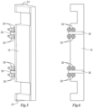
- FIG. 5 shows an isometric view of the carrier 16 of FIGs. 3 and 4 with additional elements as will be described herein.
- the carrier 16 has a lip 24 that fits under the gib 20 that allows the carrier 16 to be held against the mold half 12.
- the carrier 16 has cam bars 26 that are mounted to the carrier 16.
- the cam bars 26 may alternatively be integral with the carrier 16.
- the cam bars 26 extend into a trench 30 that is formed in the mold half 12.
- the trench 30 defines the movement path of the slide assembly 14 in the mold half 12.
- a series of rollers 28 are arranged to engage with the carrier 16.
- rollers 28 engage with the carrier 16 by engaging with the cam bars 26.
- the rollers 28 are recessed within the mold half 12 and roll with the movement of the carrier 16 parallel to the parting line of the two mold halves.
- the rollers 28 do not bear any of the compression force used to press the two mold halves together during part formation.
- rollers 28 themselves are not powered or driven in any way. Instead, they move with the cam bars 26 as the carrier 16 is moved in whichever direction the slide assembly 14 is actuated. This reduces the friction of the movement of slide assembly 14 as it actuates during part formation.
- FIG. 6 shows a bottom view of the carrier 16 of FIG. 5 which better illustrates the arrangement of the rollers 28 relative to the carrier 16 and the cam bars 26.
- the actual number and orientation of the rollers 28 could be varied. There could be any number of rollers 28 and they do not have to be on both sides of the cam bars 26 as shown in the figures.
- rollers 28 and the cam bars 26 improves the alignment of the component parts of the slide assembly 14 as well as reduces the surface wear of the various parts. More accurately aligning these surfaces reduces the overall wear of the slide assembly 14 and potentially on molding surfaces that are mating on the slide faces.
- FIG. 7 shows the bottom view of another carrier 16a with only one cam bar 26a. As with the earlier shown embodiment, there could be any number of rollers 28a and they do not have to be on both sides of the cam bar 26a.
- FIG. 8 shows the bottom view of another carrier 16b in which there are no cam bars mounted to the carrier 16b.
- the rollers 28b are arranged on either side of the carrier 16b and would be located under the gibs (not shown).
- the rollers 28b would extend above the surface of the mold half (not shown) but because they would be located under the gibs, they would still not bear any compression force when the mold halves are pressed together.
Landscapes
- Engineering & Computer Science (AREA)
- Manufacturing & Machinery (AREA)
- Mechanical Engineering (AREA)
- Moulds For Moulding Plastics Or The Like (AREA)
- Injection Moulding Of Plastics Or The Like (AREA)
Description
- injection molding is a manufacturing process for producing parts by injecting material into a mold. Injection molding machines comprise various components that work together to ultimately form a plastic or silicone part that is ejected from the mold. The basic parts of the mold are the cavity and ejector system. The mold comprises at least two mold halves within which the cavity is formed. When the two mold halves are closed, plastic or silicone is injected into the cavity to form the molded part. The mold halves are then split apart to remove or eject the finally molded part. To form more complex molded parts, additional movable and slidable elements on the mold halves operate to hold additional cavity elements and to release the finally molded part from the mold. The surfaces of these slidable elements are typically bound by surface to surface contact creating significant friction and wear. What is presented is an improved system to guide the movement of these injection mold components in an injection molding machine mold.
-
CN102452148B describes a structure for driving mould translation in a double-color injection moulding machine. The structure comprises a mould moving base plate, an upper pressure plate, a lower pressure plate, a bevel plate, a hydraulic motor, a gear box, a rack and a cross beam. The hydraulic motor, the gear box and the rack form a transmission unit; the mould moving base plate, the upper pressure plate, the lower pressure plate and the cross beam form a slide rail unit; and the lower pressure plate, the cross beam and the bevel plate form a bearing unit. A moving mould is fixed with the rack through a positioning key, and reciprocates in parallel along three rolling slide rails of the slide rail unit under the driving of the hydraulic motor and the control of a limit travel switch so as to achieve the aim of matching the same moving mould with different fixed moulds on a fixed mould plate and changing the mould cavity. -
CN204019904U describes a step tee top type demoulding mechanism, which comprises a mould frame, wherein the mould frame is provided with an upper and a lower pressing plates, the upper pressing plate is provided with a fixed mould, an ejection mechanism is arranged on the lower pressing plate, a moving mould is arranged between the ejection mechanism and the fixed mould, the ejection mechanism comprises an ejector pin seat and an ejection block, the moving mould is provided with a moving module, the ejection block is fixed in the moving module, an ejector pin is arranged on the ejector pin seat, and runs through the moving mould and is supported with the ejection block, a mould cavity is arranged between the ejection block and the fixed mould, core-pulling mechanisms are arranged on the two sides of the mould cavity, and a mold core mechanism which is penetrated into the mould cavity is arranged on the bottom portion of the mould cavity. - The invention is set out in the appended set of claims.
- For a more complete understanding and appreciation of this invention, and its many advantages, reference will be made to the following detailed description taken in conjunction with the accompanying drawings.
-
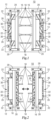
FIG. 1 shows a portion of one mold half of an injection molding system with the slide assembly in the closed position; -
FIG. 2 shows the mold half ofFIG. 1 with the slide assembly in the open position; -
FIG. 3 is a close-up of one slide assembly ofFIG. 1 ; -
FIG. 4 is a view of some of the slide assembly components shown inFIG. 3 ; -
FIG. 5 is an isometric view of the carrier and select components shown inFIG. 4 ; -
FIG. 6 is a bottom view of the carrier and select components ofFIG. 5 ; -
FIG. 7 is a bottom view of another embodiment showing a carrier having a single cam bar; and -
FIG. 8 is a bottom view of another embodiment showing a carrier with no cam bars. - Referring to the drawings, some of the reference numerals are used to designate the same or corresponding parts through several of the embodiments and figures shown and described. Corresponding parts are denoted in different embodiments with the addition of lowercase letters. Variations of corresponding parts in form or function that are depicted in the figures are described. It will be understood that variations in the embodiments can generally be interchanged without deviating from the invention.
- Plastic and silicone injection molding processing machines form molded parts based on the injection of liquid plastic or silicone into a cavity that is formed into at least two mold halves that separate at a parting line. During part formation, the two mold halves are compressed together to hold the cavities shut and to prevent the leakage of liquid plastic or silicone from between the two halves. The pressures exerted are typically high and parts that are not reinforced are prone to wear and damage. For more complicated parts, a slide assembly may be incorporated onto one or both mold halves to hold additional cavity forming parts. These slide assemblies are crafted and machined with care to prolong their life and usefulness.
- For purposes of illustration,
FIG. 1 shows a simplified portion of a plastic and/orsilicone mold 10. Only onemold half 12 is shown while in reality, a second mold half would be pressing against thismold half 12 and forming a tight seal in preparation for the injection of plastic or silicone into the cavity. Furthermore, the cavity within themold half 12 is also not shown to simplify the drawings. Eachmold half 12 can hold at least oneslide assembly 14, as in the example shown inFIG. 1 , but it is understood that themold halves 12 can hold asmany slide assemblies 14 as may be arranged to fit on themold half 12. Theslide assembly 14 is in the closed position inFIG. 1 . Eachslide assembly 14 comprises acarrier 16 for holdingcavity forming parts 18 andgibs 20 that hold thecarrier 16 to themold half 12. Thecavity forming parts 18 shown in the figures are depicted merely for purposes of illustration. It will be understood that the actual form and design of thecavity forming parts 18 will be as necessary for the particular application. - As best understood by comparing
FIGs. 1 and 2 , after the plastic or silicone is injected into the cavity, the two mold halves are pulled apart to eject the finally molded part. Theslide assembly 14 also moves parallel to the plane of the parting line of the two mold halves and generally perpendicular to the direction of the plane of separation of the two mold halves after a part has been formed. The movement of theslide assemblies 14 can be actuated in several different ways. Theslide assemblies 14 can be mechanically opened and closed using cam pins, horn pins, cam fingers, or delta cams. Alternatively, theslide assemblies 14 could be piston driven hydraulic or pneumatic systems or electric servo driven. Regardless of the means of movement, allslide assemblies 14 will benefit from the improvements disclosed herein. -
FIG. 3 shows a close-up of one of theslide assemblies 14 on amold half 12. For purposes of illustration, the cavity forming parts are not shown. Thecarrier 16 is held in place on themold half 12 with a pair ofgibs 20. At least onewear plate 22 is mounted between thecarrier 16 and themold half 12. Thecarrier 16 slides on thewear plates 22 to reduce wear on themold half 12 as thecarriers 16 slide over them. -
FIG. 4 shows thesame slide assembly 14 ofFIG. 3 , without thegibs 20 and thewear plates 22.FIG. 5 shows an isometric view of thecarrier 16 ofFIGs. 3 and 4 with additional elements as will be described herein. As best understood by comparingFIGs. 3, 4 , and5 , thecarrier 16 has alip 24 that fits under thegib 20 that allows thecarrier 16 to be held against themold half 12. In the embodiment shown, thecarrier 16 hascam bars 26 that are mounted to thecarrier 16. Thecam bars 26 may alternatively be integral with thecarrier 16. Thecam bars 26 extend into atrench 30 that is formed in themold half 12. Thetrench 30 defines the movement path of theslide assembly 14 in themold half 12. A series ofrollers 28 are arranged to engage with thecarrier 16. In this case, therollers 28 engage with thecarrier 16 by engaging with thecam bars 26. Therollers 28 are recessed within themold half 12 and roll with the movement of thecarrier 16 parallel to the parting line of the two mold halves. Therollers 28 do not bear any of the compression force used to press the two mold halves together during part formation. - The
rollers 28 themselves are not powered or driven in any way. Instead, they move with the cam bars 26 as thecarrier 16 is moved in whichever direction theslide assembly 14 is actuated. This reduces the friction of the movement ofslide assembly 14 as it actuates during part formation. -
FIG. 6 shows a bottom view of thecarrier 16 ofFIG. 5 which better illustrates the arrangement of therollers 28 relative to thecarrier 16 and the cam bars 26. The actual number and orientation of therollers 28 could be varied. There could be any number ofrollers 28 and they do not have to be on both sides of the cam bars 26 as shown in the figures. - The combination of the
rollers 28 and the cam bars 26 improves the alignment of the component parts of theslide assembly 14 as well as reduces the surface wear of the various parts. More accurately aligning these surfaces reduces the overall wear of theslide assembly 14 and potentially on molding surfaces that are mating on the slide faces. -
FIG. 7 shows the bottom view of anothercarrier 16a with only onecam bar 26a. As with the earlier shown embodiment, there could be any number ofrollers 28a and they do not have to be on both sides of thecam bar 26a. -
FIG. 8 shows the bottom view of anothercarrier 16b in which there are no cam bars mounted to thecarrier 16b. In this embodiment therollers 28b are arranged on either side of thecarrier 16b and would be located under the gibs (not shown). Therollers 28b would extend above the surface of the mold half (not shown) but because they would be located under the gibs, they would still not bear any compression force when the mold halves are pressed together.
Claims (8)
- A guidance system for a plastic and/or silicone injection molding machine, the guidance system comprising:two mold halves (12); anda slide assembly (14) mounted to one of said two halves (12), said slide assembly (14) including:a carrier (16) for holding cavity forming parts 18,gibs (20) securing said carrier (16) to the mold half (12) to which said slide assembly (14) is mounted, anda series of rollers (28) disposed between said carrier and said mold half, said series of rollers (28) engaged with said carrier (16) in an orientation in which as said carrier (16) moves parallel to a parting line of the two mold halves (12), said series of rollers (28) rolls with said carrier parallel to the parting line and said series of rollers (28) does not bear any compression force used to press the two mold halves (12) together.
- The guidance system of claim 1, further comprising at least one cam bar (26) mounted to said carrier (16).
- The guidance system of claim 2, wherein said series of rollers (28) engage with said at least one cam bar (26) to engage with said carrier (16).
- The guidance system of claim 3, wherein said series of rollers (28) engage with said carrier (16) on either side of each one of said at least one cam bar (26).
- The guidance system of any one of claims 1-4, further comprising a wear plate (22) mounted between said carrier (16) and said mold half (12).
- The guidance system of any one of claims 1-5, wherein the series of rollers (28) is recessed within the mold half (12).
- The guidance system of any one of claims 1-6, wherein the mold half (12) defines a trench (30), and the slide assembly (14) is movable along the trench (30).
- The guidance system of any one of claims 1- 7, wherein the series of rollers (28b) are on either side of the carrier (16b) and disposed under the gibs (20).
Applications Claiming Priority (2)
| Application Number | Priority Date | Filing Date | Title |
|---|---|---|---|
| US201962811372P | 2019-02-27 | 2019-02-27 | |
| PCT/US2020/019881 WO2020176608A1 (en) | 2019-02-27 | 2020-02-26 | Slide guidance and wear reduction for injection molding |
Publications (3)
| Publication Number | Publication Date |
|---|---|
| EP3906143A1 EP3906143A1 (en) | 2021-11-10 |
| EP3906143A4 EP3906143A4 (en) | 2022-10-05 |
| EP3906143B1 true EP3906143B1 (en) | 2023-12-20 |
Family
ID=72140237
Family Applications (1)
| Application Number | Title | Priority Date | Filing Date |
|---|---|---|---|
| EP20763931.1A Active EP3906143B1 (en) | 2019-02-27 | 2020-02-26 | Slide guidance and wear reduction for injection molding |
Country Status (8)
| Country | Link |
|---|---|
| US (1) | US11511470B2 (en) |
| EP (1) | EP3906143B1 (en) |
| CA (1) | CA3128132A1 (en) |
| ES (1) | ES2973805T3 (en) |
| FI (1) | FI3906143T3 (en) |
| HU (1) | HUE065979T2 (en) |
| MX (1) | MX2021010339A (en) |
| WO (1) | WO2020176608A1 (en) |
Families Citing this family (2)
| Publication number | Priority date | Publication date | Assignee | Title |
|---|---|---|---|---|
| CN112372965B (en) * | 2020-11-27 | 2024-08-20 | 东莞广华汽车饰件科技有限公司 | Automatic necking and twisting-off device for water gap of automobile injection molding part |
| JP7564040B2 (en) | 2021-03-26 | 2024-10-08 | 住友重機械工業株式会社 | Injection Molding Machine |
Family Cites Families (9)
| Publication number | Priority date | Publication date | Assignee | Title |
|---|---|---|---|---|
| US4172872A (en) | 1973-08-06 | 1979-10-30 | Yoshiharu Nagai | Method of molding large-sized plastics |
| US4036923A (en) * | 1975-03-03 | 1977-07-19 | Exxon Research And Engineering Company | Method for forming large reinforced foamed plastic panels |
| US4929166A (en) * | 1988-11-21 | 1990-05-29 | Husky Injection Molding Systems Ltd | Support for quick mold changing |
| US5007814A (en) | 1990-02-05 | 1991-04-16 | Saunders Raymond L | Device for separating and closing a split mold having two halves |
| AT400127B (en) | 1993-07-12 | 1995-10-25 | Engel Gmbh Maschbau | INJECTION MOLDING MACHINE |
| DE19516125C1 (en) | 1995-05-03 | 1996-06-05 | Battenfeld Fischer Blasform | Tool closure on plastics processing machine process equipment |
| GB2430641A (en) * | 2005-10-03 | 2007-04-04 | Im Pak Technologies Ltd | Injection compresson impact moulding |
| CN102452148B (en) | 2011-11-16 | 2014-03-05 | 青岛海泰科模具有限公司 | Structure for driving mould translation in double-color injection moulding machine |
| CN204019904U (en) | 2014-09-01 | 2014-12-17 | 浙江台州黄岩精正模具有限公司 | Step threeway top type mould emptier |
-
2020
- 2020-02-26 CA CA3128132A patent/CA3128132A1/en active Pending
- 2020-02-26 HU HUE20763931A patent/HUE065979T2/en unknown
- 2020-02-26 MX MX2021010339A patent/MX2021010339A/en unknown
- 2020-02-26 WO PCT/US2020/019881 patent/WO2020176608A1/en not_active Ceased
- 2020-02-26 EP EP20763931.1A patent/EP3906143B1/en active Active
- 2020-02-26 US US16/801,986 patent/US11511470B2/en active Active
- 2020-02-26 ES ES20763931T patent/ES2973805T3/en active Active
- 2020-02-26 FI FIEP20763931.1T patent/FI3906143T3/en active
Also Published As
| Publication number | Publication date |
|---|---|
| MX2021010339A (en) | 2021-09-28 |
| WO2020176608A1 (en) | 2020-09-03 |
| FI3906143T3 (en) | 2024-03-13 |
| EP3906143A1 (en) | 2021-11-10 |
| HUE065979T2 (en) | 2024-07-28 |
| EP3906143A4 (en) | 2022-10-05 |
| US11511470B2 (en) | 2022-11-29 |
| US20200269481A1 (en) | 2020-08-27 |
| ES2973805T3 (en) | 2024-06-24 |
| CA3128132A1 (en) | 2020-09-03 |
Similar Documents
| Publication | Publication Date | Title |
|---|---|---|
| US5320511A (en) | Multiple-injection molding using single-injection machines | |
| KR101482985B1 (en) | Cam slide assembly for treatment of undercut in injection mould | |
| US11511470B2 (en) | Slide guidance and wear reduction for injection molding | |
| US20210078225A1 (en) | Platen apparatus for center section of a stack mold injection molding machine | |
| US4861258A (en) | Press and method for molding plastics articles, in particular thermoplastic, thermosetting and polyurethane polymeric articles | |
| KR20210083960A (en) | apparatus for plastic injection molding | |
| CN115609852B (en) | A molding die for a two-color overmolded product | |
| KR20220041683A (en) | Mold device | |
| KR102245871B1 (en) | Injection mold with fixed hydraulic slide actuator with improved separation efficiency | |
| KR101889364B1 (en) | Injection mold machine with a hydraulic cam slide assembly | |
| KR102245873B1 (en) | Injection mold with fixed hydraulic slide actuator with improved compression efficiency | |
| KR102187481B1 (en) | Control method for injection molds and injection molds for manufacturing injection products with upper/lower undercuts | |
| KR101289359B1 (en) | Injection molding machine | |
| US20040207119A1 (en) | Rack & pinion ejector guiding system for a molding machine | |
| TW202336880A (en) | Resin sealing device | |
| JP2002347085A (en) | Injection-molding mold | |
| KR101960814B1 (en) | core extractor device having injection | |
| KR100787196B1 (en) | Inner undercut molding apparatus of mold assembly and its method | |
| CN219114664U (en) | Secondary demoulding mechanism of piston | |
| KR102149921B1 (en) | Injection mold with fixed hydraulic slide actuator | |
| CN219338383U (en) | Tire pressure sensor shell injection mold | |
| CN219543893U (en) | A mould structure for preparing display buckle | |
| EP4644086A1 (en) | Slider assembly for injection moulds | |
| CN219748774U (en) | Injection mold of comb body | |
| KR101229836B1 (en) | A injection compression mould with divided push blocks and an injection compression moulding method |
Legal Events
| Date | Code | Title | Description |
|---|---|---|---|
| STAA | Information on the status of an ep patent application or granted ep patent |
Free format text: STATUS: THE INTERNATIONAL PUBLICATION HAS BEEN MADE |
|
| PUAI | Public reference made under article 153(3) epc to a published international application that has entered the european phase |
Free format text: ORIGINAL CODE: 0009012 |
|
| STAA | Information on the status of an ep patent application or granted ep patent |
Free format text: STATUS: REQUEST FOR EXAMINATION WAS MADE |
|
| 17P | Request for examination filed |
Effective date: 20210728 |
|
| AK | Designated contracting states |
Kind code of ref document: A1 Designated state(s): AL AT BE BG CH CY CZ DE DK EE ES FI FR GB GR HR HU IE IS IT LI LT LU LV MC MK MT NL NO PL PT RO RS SE SI SK SM TR |
|
| DAV | Request for validation of the european patent (deleted) | ||
| DAX | Request for extension of the european patent (deleted) | ||
| A4 | Supplementary search report drawn up and despatched |
Effective date: 20220907 |
|
| RIC1 | Information provided on ipc code assigned before grant |
Ipc: B29C 45/00 20060101ALI20220901BHEP Ipc: B29C 33/00 20060101ALI20220901BHEP Ipc: B29C 33/20 20060101AFI20220901BHEP |
|
| REG | Reference to a national code |
Free format text: PREVIOUS MAIN CLASS: B29C0033200000 Ipc: B29C0045260000 Ref country code: DE Ref legal event code: R079 Ref document number: 602020023122 Country of ref document: DE |
|
| GRAP | Despatch of communication of intention to grant a patent |
Free format text: ORIGINAL CODE: EPIDOSNIGR1 |
|
| STAA | Information on the status of an ep patent application or granted ep patent |
Free format text: STATUS: GRANT OF PATENT IS INTENDED |
|
| RIC1 | Information provided on ipc code assigned before grant |
Ipc: B29C 45/44 20060101ALI20230517BHEP Ipc: B29C 45/26 20060101AFI20230517BHEP |
|
| INTG | Intention to grant announced |
Effective date: 20230607 |
|
| P01 | Opt-out of the competence of the unified patent court (upc) registered |
Effective date: 20230728 |
|
| GRAS | Grant fee paid |
Free format text: ORIGINAL CODE: EPIDOSNIGR3 |
|
| GRAA | (expected) grant |
Free format text: ORIGINAL CODE: 0009210 |
|
| STAA | Information on the status of an ep patent application or granted ep patent |
Free format text: STATUS: THE PATENT HAS BEEN GRANTED |
|
| AK | Designated contracting states |
Kind code of ref document: B1 Designated state(s): AL AT BE BG CH CY CZ DE DK EE ES FI FR GB GR HR HU IE IS IT LI LT LU LV MC MK MT NL NO PL PT RO RS SE SI SK SM TR |
|
| REG | Reference to a national code |
Ref country code: GB Ref legal event code: FG4D |
|
| REG | Reference to a national code |
Ref country code: DE Ref legal event code: R096 Ref document number: 602020023122 Country of ref document: DE |
|
| REG | Reference to a national code |
Ref country code: CH Ref legal event code: EP |
|
| REG | Reference to a national code |
Ref country code: IE Ref legal event code: FG4D |
|
| REG | Reference to a national code |
Ref country code: SE Ref legal event code: TRGR |
|
| REG | Reference to a national code |
Ref country code: FI Ref legal event code: FGE |
|
| PG25 | Lapsed in a contracting state [announced via postgrant information from national office to epo] |
Ref country code: GR Free format text: LAPSE BECAUSE OF FAILURE TO SUBMIT A TRANSLATION OF THE DESCRIPTION OR TO PAY THE FEE WITHIN THE PRESCRIBED TIME-LIMIT Effective date: 20240321 |
|
| REG | Reference to a national code |
Ref country code: LT Ref legal event code: MG9D |
|
| PG25 | Lapsed in a contracting state [announced via postgrant information from national office to epo] |
Ref country code: LT Free format text: LAPSE BECAUSE OF FAILURE TO SUBMIT A TRANSLATION OF THE DESCRIPTION OR TO PAY THE FEE WITHIN THE PRESCRIBED TIME-LIMIT Effective date: 20231220 |
|
| REG | Reference to a national code |
Ref country code: NL Ref legal event code: MP Effective date: 20231220 |
|
| PG25 | Lapsed in a contracting state [announced via postgrant information from national office to epo] |
Ref country code: LT Free format text: LAPSE BECAUSE OF FAILURE TO SUBMIT A TRANSLATION OF THE DESCRIPTION OR TO PAY THE FEE WITHIN THE PRESCRIBED TIME-LIMIT Effective date: 20231220 Ref country code: GR Free format text: LAPSE BECAUSE OF FAILURE TO SUBMIT A TRANSLATION OF THE DESCRIPTION OR TO PAY THE FEE WITHIN THE PRESCRIBED TIME-LIMIT Effective date: 20240321 Ref country code: BG Free format text: LAPSE BECAUSE OF FAILURE TO SUBMIT A TRANSLATION OF THE DESCRIPTION OR TO PAY THE FEE WITHIN THE PRESCRIBED TIME-LIMIT Effective date: 20240320 |
|
| PG25 | Lapsed in a contracting state [announced via postgrant information from national office to epo] |
Ref country code: NL Free format text: LAPSE BECAUSE OF FAILURE TO SUBMIT A TRANSLATION OF THE DESCRIPTION OR TO PAY THE FEE WITHIN THE PRESCRIBED TIME-LIMIT Effective date: 20231220 |
|
| PG25 | Lapsed in a contracting state [announced via postgrant information from national office to epo] |
Ref country code: RS Free format text: LAPSE BECAUSE OF FAILURE TO SUBMIT A TRANSLATION OF THE DESCRIPTION OR TO PAY THE FEE WITHIN THE PRESCRIBED TIME-LIMIT Effective date: 20231220 Ref country code: NO Free format text: LAPSE BECAUSE OF FAILURE TO SUBMIT A TRANSLATION OF THE DESCRIPTION OR TO PAY THE FEE WITHIN THE PRESCRIBED TIME-LIMIT Effective date: 20240320 Ref country code: NL Free format text: LAPSE BECAUSE OF FAILURE TO SUBMIT A TRANSLATION OF THE DESCRIPTION OR TO PAY THE FEE WITHIN THE PRESCRIBED TIME-LIMIT Effective date: 20231220 Ref country code: LV Free format text: LAPSE BECAUSE OF FAILURE TO SUBMIT A TRANSLATION OF THE DESCRIPTION OR TO PAY THE FEE WITHIN THE PRESCRIBED TIME-LIMIT Effective date: 20231220 Ref country code: HR Free format text: LAPSE BECAUSE OF FAILURE TO SUBMIT A TRANSLATION OF THE DESCRIPTION OR TO PAY THE FEE WITHIN THE PRESCRIBED TIME-LIMIT Effective date: 20231220 |
|
| REG | Reference to a national code |
Ref country code: ES Ref legal event code: FG2A Ref document number: 2973805 Country of ref document: ES Kind code of ref document: T3 Effective date: 20240624 |
|
| PG25 | Lapsed in a contracting state [announced via postgrant information from national office to epo] |
Ref country code: IS Free format text: LAPSE BECAUSE OF FAILURE TO SUBMIT A TRANSLATION OF THE DESCRIPTION OR TO PAY THE FEE WITHIN THE PRESCRIBED TIME-LIMIT Effective date: 20240420 |
|
| REG | Reference to a national code |
Ref country code: HU Ref legal event code: AG4A Ref document number: E065979 Country of ref document: HU |
|
| PG25 | Lapsed in a contracting state [announced via postgrant information from national office to epo] |
Ref country code: SK Free format text: LAPSE BECAUSE OF FAILURE TO SUBMIT A TRANSLATION OF THE DESCRIPTION OR TO PAY THE FEE WITHIN THE PRESCRIBED TIME-LIMIT Effective date: 20231220 |
|
| PG25 | Lapsed in a contracting state [announced via postgrant information from national office to epo] |
Ref country code: SM Free format text: LAPSE BECAUSE OF FAILURE TO SUBMIT A TRANSLATION OF THE DESCRIPTION OR TO PAY THE FEE WITHIN THE PRESCRIBED TIME-LIMIT Effective date: 20231220 Ref country code: SK Free format text: LAPSE BECAUSE OF FAILURE TO SUBMIT A TRANSLATION OF THE DESCRIPTION OR TO PAY THE FEE WITHIN THE PRESCRIBED TIME-LIMIT Effective date: 20231220 Ref country code: RO Free format text: LAPSE BECAUSE OF FAILURE TO SUBMIT A TRANSLATION OF THE DESCRIPTION OR TO PAY THE FEE WITHIN THE PRESCRIBED TIME-LIMIT Effective date: 20231220 Ref country code: IS Free format text: LAPSE BECAUSE OF FAILURE TO SUBMIT A TRANSLATION OF THE DESCRIPTION OR TO PAY THE FEE WITHIN THE PRESCRIBED TIME-LIMIT Effective date: 20240420 Ref country code: EE Free format text: LAPSE BECAUSE OF FAILURE TO SUBMIT A TRANSLATION OF THE DESCRIPTION OR TO PAY THE FEE WITHIN THE PRESCRIBED TIME-LIMIT Effective date: 20231220 |
|
| PG25 | Lapsed in a contracting state [announced via postgrant information from national office to epo] |
Ref country code: PL Free format text: LAPSE BECAUSE OF FAILURE TO SUBMIT A TRANSLATION OF THE DESCRIPTION OR TO PAY THE FEE WITHIN THE PRESCRIBED TIME-LIMIT Effective date: 20231220 Ref country code: PT Free format text: LAPSE BECAUSE OF FAILURE TO SUBMIT A TRANSLATION OF THE DESCRIPTION OR TO PAY THE FEE WITHIN THE PRESCRIBED TIME-LIMIT Effective date: 20240422 |
|
| PG25 | Lapsed in a contracting state [announced via postgrant information from national office to epo] |
Ref country code: PT Free format text: LAPSE BECAUSE OF FAILURE TO SUBMIT A TRANSLATION OF THE DESCRIPTION OR TO PAY THE FEE WITHIN THE PRESCRIBED TIME-LIMIT Effective date: 20240422 Ref country code: PL Free format text: LAPSE BECAUSE OF FAILURE TO SUBMIT A TRANSLATION OF THE DESCRIPTION OR TO PAY THE FEE WITHIN THE PRESCRIBED TIME-LIMIT Effective date: 20231220 |
|
| REG | Reference to a national code |
Ref country code: DE Ref legal event code: R097 Ref document number: 602020023122 Country of ref document: DE |
|
| PG25 | Lapsed in a contracting state [announced via postgrant information from national office to epo] |
Ref country code: MC Free format text: LAPSE BECAUSE OF FAILURE TO SUBMIT A TRANSLATION OF THE DESCRIPTION OR TO PAY THE FEE WITHIN THE PRESCRIBED TIME-LIMIT Effective date: 20231220 |
|
| PG25 | Lapsed in a contracting state [announced via postgrant information from national office to epo] |
Ref country code: DK Free format text: LAPSE BECAUSE OF FAILURE TO SUBMIT A TRANSLATION OF THE DESCRIPTION OR TO PAY THE FEE WITHIN THE PRESCRIBED TIME-LIMIT Effective date: 20231220 |
|
| PLBE | No opposition filed within time limit |
Free format text: ORIGINAL CODE: 0009261 |
|
| STAA | Information on the status of an ep patent application or granted ep patent |
Free format text: STATUS: NO OPPOSITION FILED WITHIN TIME LIMIT |
|
| PG25 | Lapsed in a contracting state [announced via postgrant information from national office to epo] |
Ref country code: SI Free format text: LAPSE BECAUSE OF FAILURE TO SUBMIT A TRANSLATION OF THE DESCRIPTION OR TO PAY THE FEE WITHIN THE PRESCRIBED TIME-LIMIT Effective date: 20231220 |
|
| PG25 | Lapsed in a contracting state [announced via postgrant information from national office to epo] |
Ref country code: SI Free format text: LAPSE BECAUSE OF FAILURE TO SUBMIT A TRANSLATION OF THE DESCRIPTION OR TO PAY THE FEE WITHIN THE PRESCRIBED TIME-LIMIT Effective date: 20231220 Ref country code: DK Free format text: LAPSE BECAUSE OF FAILURE TO SUBMIT A TRANSLATION OF THE DESCRIPTION OR TO PAY THE FEE WITHIN THE PRESCRIBED TIME-LIMIT Effective date: 20231220 |
|
| 26N | No opposition filed |
Effective date: 20240923 |
|
| PG25 | Lapsed in a contracting state [announced via postgrant information from national office to epo] |
Ref country code: IE Free format text: LAPSE BECAUSE OF NON-PAYMENT OF DUE FEES Effective date: 20240226 |
|
| PG25 | Lapsed in a contracting state [announced via postgrant information from national office to epo] |
Ref country code: IE Free format text: LAPSE BECAUSE OF NON-PAYMENT OF DUE FEES Effective date: 20240226 |
|
| REG | Reference to a national code |
Ref country code: AT Ref legal event code: UEP Ref document number: 1642117 Country of ref document: AT Kind code of ref document: T Effective date: 20231220 |
|
| PG25 | Lapsed in a contracting state [announced via postgrant information from national office to epo] |
Ref country code: CY Free format text: LAPSE BECAUSE OF FAILURE TO SUBMIT A TRANSLATION OF THE DESCRIPTION OR TO PAY THE FEE WITHIN THE PRESCRIBED TIME-LIMIT; INVALID AB INITIO Effective date: 20200226 |
|
| PG25 | Lapsed in a contracting state [announced via postgrant information from national office to epo] |
Ref country code: TR Free format text: LAPSE BECAUSE OF FAILURE TO SUBMIT A TRANSLATION OF THE DESCRIPTION OR TO PAY THE FEE WITHIN THE PRESCRIBED TIME-LIMIT Effective date: 20231220 |
|
| REG | Reference to a national code |
Ref country code: CH Ref legal event code: U11 Free format text: ST27 STATUS EVENT CODE: U-0-0-U10-U11 (AS PROVIDED BY THE NATIONAL OFFICE) Effective date: 20260301 |
|
| PGFP | Annual fee paid to national office [announced via postgrant information from national office to epo] |
Ref country code: LU Payment date: 20260220 Year of fee payment: 7 |
|
| PGFP | Annual fee paid to national office [announced via postgrant information from national office to epo] |
Ref country code: HU Payment date: 20260226 Year of fee payment: 7 |
|
| PGFP | Annual fee paid to national office [announced via postgrant information from national office to epo] |
Ref country code: SE Payment date: 20260223 Year of fee payment: 7 |
|
| PGFP | Annual fee paid to national office [announced via postgrant information from national office to epo] |
Ref country code: GB Payment date: 20260223 Year of fee payment: 7 |
|
| PGFP | Annual fee paid to national office [announced via postgrant information from national office to epo] |
Ref country code: ES Payment date: 20260317 Year of fee payment: 7 |
|
| PGFP | Annual fee paid to national office [announced via postgrant information from national office to epo] |
Ref country code: DE Payment date: 20260220 Year of fee payment: 7 |
|
| PGFP | Annual fee paid to national office [announced via postgrant information from national office to epo] |
Ref country code: AT Payment date: 20260218 Year of fee payment: 7 |
|
| PGFP | Annual fee paid to national office [announced via postgrant information from national office to epo] |
Ref country code: FI Payment date: 20260220 Year of fee payment: 7 Ref country code: BE Payment date: 20260220 Year of fee payment: 7 Ref country code: IT Payment date: 20260220 Year of fee payment: 7 |
|
| PGFP | Annual fee paid to national office [announced via postgrant information from national office to epo] |
Ref country code: FR Payment date: 20260224 Year of fee payment: 7 |
|
| PGFP | Annual fee paid to national office [announced via postgrant information from national office to epo] |
Ref country code: CH Payment date: 20260301 Year of fee payment: 7 Ref country code: CZ Payment date: 20260218 Year of fee payment: 7 |