EP3905873A1 - Work head and work machine - Google Patents
Work head and work machine Download PDFInfo
- Publication number
- EP3905873A1 EP3905873A1 EP18944757.6A EP18944757A EP3905873A1 EP 3905873 A1 EP3905873 A1 EP 3905873A1 EP 18944757 A EP18944757 A EP 18944757A EP 3905873 A1 EP3905873 A1 EP 3905873A1
- Authority
- EP
- European Patent Office
- Prior art keywords
- claws
- section
- gripping
- component
- work
- Prior art date
- Legal status (The legal status is an assumption and is not a legal conclusion. Google has not performed a legal analysis and makes no representation as to the accuracy of the status listed.)
- Granted
Links
Images





Classifications
-
- B—PERFORMING OPERATIONS; TRANSPORTING
- B25—HAND TOOLS; PORTABLE POWER-DRIVEN TOOLS; MANIPULATORS
- B25J—MANIPULATORS; CHAMBERS PROVIDED WITH MANIPULATION DEVICES
- B25J15/00—Gripping heads and other end effectors
- B25J15/08—Gripping heads and other end effectors having finger members
-
- B—PERFORMING OPERATIONS; TRANSPORTING
- B25—HAND TOOLS; PORTABLE POWER-DRIVEN TOOLS; MANIPULATORS
- B25J—MANIPULATORS; CHAMBERS PROVIDED WITH MANIPULATION DEVICES
- B25J15/00—Gripping heads and other end effectors
- B25J15/0033—Gripping heads and other end effectors with gripping surfaces having special shapes
-
- B—PERFORMING OPERATIONS; TRANSPORTING
- B25—HAND TOOLS; PORTABLE POWER-DRIVEN TOOLS; MANIPULATORS
- B25J—MANIPULATORS; CHAMBERS PROVIDED WITH MANIPULATION DEVICES
- B25J15/00—Gripping heads and other end effectors
- B25J15/02—Gripping heads and other end effectors servo-actuated
- B25J15/0253—Gripping heads and other end effectors servo-actuated comprising parallel grippers
- B25J15/0293—Gripping heads and other end effectors servo-actuated comprising parallel grippers having fingers directly connected to actuator
-
- B—PERFORMING OPERATIONS; TRANSPORTING
- B25—HAND TOOLS; PORTABLE POWER-DRIVEN TOOLS; MANIPULATORS
- B25J—MANIPULATORS; CHAMBERS PROVIDED WITH MANIPULATION DEVICES
- B25J9/00—Program-controlled manipulators
- B25J9/10—Program-controlled manipulators characterised by positioning means for manipulator elements
- B25J9/14—Program-controlled manipulators characterised by positioning means for manipulator elements fluid
-
- H—ELECTRICITY
- H05—ELECTRIC TECHNIQUES NOT OTHERWISE PROVIDED FOR
- H05K—PRINTED CIRCUITS; CASINGS OR CONSTRUCTIONAL DETAILS OF ELECTRIC APPARATUS; MANUFACTURE OF ASSEMBLAGES OF ELECTRICAL COMPONENTS
- H05K13/00—Apparatus or processes specially adapted for manufacturing or adjusting assemblages of electric components
- H05K13/04—Mounting of components, e.g. of leadless components
- H05K13/0404—Pick-and-place heads or apparatus, e.g. with jaws
-
- H—ELECTRICITY
- H05—ELECTRIC TECHNIQUES NOT OTHERWISE PROVIDED FOR
- H05K—PRINTED CIRCUITS; CASINGS OR CONSTRUCTIONAL DETAILS OF ELECTRIC APPARATUS; MANUFACTURE OF ASSEMBLAGES OF ELECTRICAL COMPONENTS
- H05K13/00—Apparatus or processes specially adapted for manufacturing or adjusting assemblages of electric components
- H05K13/04—Mounting of components, e.g. of leadless components
- H05K13/0404—Pick-and-place heads or apparatus, e.g. with jaws
- H05K13/0408—Incorporating a pick-up tool
Definitions
- the present invention relates to a work head that holds a component, and a work machine including the work head.
- Patent Literature 1 discloses such a work head and a work machine.
- Patent Literature 1 JP-A-H4-083399
- the present invention has been made in view of such circumstances, and is to more preferably hold a component by a work head.
- a work head including a head main body, multiple movable bodies held to be approachable to or separatable from each other by the head main body, and an air passage formed, being open between the multiple movable bodies, in the head main body, in which the work head grips a holding tool, being configured to hold a component, by causing the multiple movable bodies to approach the holding tool to be communicated with the air passage, so that the holding tool holds the component by air supplied thereto via the air passage.
- the present description discloses a work machine including the work head, a moving device configured to move the work head, a control device configured to control operation of the moving device, and an accommodation section configured to accommodate the claws
- the fixing mechanism includes an engaging body configured to move between an engaging position with the claws and a disengaging position from the claws, and is configured to fix the claws by engagement of the engaging body with the claws and separate the claws by disengagement, and by controlling the operation of the moving device by the control device such that the engaging body abuts on an abutting section formed in the accommodation section in a state in which the claws are fixed to the movable bodies, the engaging body is moved from the engaging position with the claws to the disengaging position from the claws, the claws are separated from the movable bodies, and the claws are accommodated in the accommodation section.
- the holding tool is mounted on the work head by being gripped by the multiple movable bodies. Therefore, the work head can preferably hold the component.
- Fig. 1 shows component mounting machine 10.
- Component mounting machine 10 is a device that performs a mounting work of a component to circuit substrate 12.
- Component mounting machine 10 includes device main body 20, substrate conveyance and holding device 22, component supply device 24, bulk component supply device 26, component mounting device 28, and control device 30 (see Fig. 23 ).
- Examples of circuit substrate 12 include a circuit board, a substrate which has a three-dimensional structure, and the like, and examples of the circuit board include a printed wiring board, a printed circuit board, and the like.
- Device main body 20 is configured by frame 40 and beam 42 suspended on frame 40.
- Substrate conveyance and holding device 22 is disposed at the center of frame 40 in the front-rear direction, and includes conveyance device 50 and clamping device 52.
- Conveyance device 50 is a device that conveys circuit substrate 12
- clamping device 52 is a device that holds circuit substrate 12. With this, substrate conveyance and holding device 22 conveys circuit substrate 12 and fixedly holds circuit substrate 12 at a predetermined position.
- the conveyance direction of circuit substrate 12 is referred to as the X-direction
- the horizontal direction perpendicular to the X-direction is referred to as the Y-direction
- the vertical direction is referred to as the Z-direction.
- Component supply device 24 is disposed at a first end portion of frame 40 in the front-rear direction.
- Component supply device 24 includes tray-type component supply device 60 and feeder-type component supply device 62 (see Fig. 23 ).
- Tray-type component supply device 60 is a device that supplies the component loaded on a tray.
- Feeder-type component supply device 62 is a device that supplies the component by a tape feeder and a stick feeder (not illustrated).
- Bulk component supply device 26 is disposed at a second end portion of frame 40 in the front-rear direction.
- Bulk component supply device 26 is a device that aligns multiple scattered components to supply the components in an aligned state. That is, bulk component supply device 32 is a device that aligns the multiple components in any orientation to a predetermined orientation to supply the components in the predetermined orientation.
- Examples of the component supplied by component supply device 24 and bulk component supply device 26 include an electronic circuit component, components of a solar cell, components of a power module, and the like.
- Examples of the electronic circuit component include a component with leads, a component without leads, and the like.
- Component mounting device 28 is disposed on beam 42 and includes two work heads 70 and 72 and work head moving device 76.
- Work head moving device 76 is configured by X-direction moving device 78, Y-direction moving device 80, and Z-direction moving device 82.
- X-direction moving device 78 and Y-direction moving device 80 have electromagnetic motors 84 and 86, respectively (see Fig. 23 ), and two work heads 70 and 72 are integrally moved to any positions on frame 40 by the operation of each of electromagnetic motors 84 and 86.
- Z-direction moving device 82 has electromagnetic motors 88 and 90 (see Fig. 23 ), and sliders 92 and 94 are individually moved in the up-down direction by the operation of each of electromagnetic motors 88 and 90.
- work heads 70 and 72 are mounted on sliders 92 and 94 so as to be mounted on and separated from sliders 92 and 94. As a result, work heads 70 and 72 are individually moved in the up-down direction by Z-direction moving
- Work heads 70 and 72 mount the component on circuit substrate 12. As shown in Figs. 3 and 4 , work heads 70 and 72 are each configured by head main body 100, mounting section 102, and driving mechanism 104.
- Mounting section 102 is a section on which a holding tool, a gripping claw, and the like described in detail below are mounted, and the holding tool, the gripping claw, and the like, which are mounted on mounting section 102, hold the component by the driving of driving mechanism 104.
- driving mechanism 104 includes first shaft 110, second shaft 112, belt 114, pair of nuts 116 and 118, and pair of sliders 120 and 122.
- First shaft 110 is held by head main body 100 so as to be rotatable around the axial center in an orientation extending in the horizontal direction, and is controllably rotated by the driving of electromagnetic motor 126 (see Fig. 23 ).
- Second shaft 112 is held by head main body 100 below first shaft 110 so as to be rotatable around the axial center in an orientation parallel to first shaft 110.
- Belt 114 is wound around an end portion of first shaft 110 and an end portion of second shaft 112. As a result, second shaft 112 is also rotated in accordance with the rotation of first shaft 110.
- Pair of nuts 116 and 118 are fitted into second shaft 112 in a separated state via a ball screw mechanism (not illustrated), and pair of nuts 116 and 118 are held by head main body 100 so as to be slidable along the axial direction of second shaft 112. As a result, pair of nuts 116 and 118 approach or separate from each other in accordance with rotation of second shaft 112. Pair of sliders 120 and 122 are held on a lower face side of head main body 100 so as to be slidable along the axial direction of second shaft 112, and are fixed to pair of nuts 116 and 118. With such a structure, in driving mechanism 104, first shaft 110 is rotated by the driving of electromagnetic motor 126, and pair of sliders 120 and 122 approach or separate from each other.
- Flange section 127 is formed in first shaft 110, and brake pad 128 is disposed so as to face flange section 127.
- Brake pad 128 is biased in a direction approaching flange section 127 by a compression coil spring (not illustrated), but is separated from flange section 127 against the elastic force of the compression coil spring by the drive force of electromagnetic motor 126 when power is supplied to electromagnetic motor 126.
- a compression coil spring not illustrated
- brake pad 128 is pressed to flange section 127 by the elastic force of the compression coil spring.
- the approach or separation of pair of sliders 120 and 122 is inhibited during a power failure or the like.
- mounting section 102 is configured by pair of gripping blocks 130 and 132, and connecting block 134.
- Pair of gripping blocks 130 and 132 have a generally rectangular parallelepiped shape and are disposed on a lower face side of pair of sliders 120 and 122 in a state in which the side faces of gripping blocks 130 and 132 face each other. Gripping blocks 130 and 132 are held by sliders 120 and 122 so as to be slidable in the up-down direction, and are biased downward by compression coil springs 136 and 138.
- gripping grooves 140 and 142 are formed on opposing side faces of pair of gripping blocks 130 and 132 so as to extend in the width direction of the side faces.
- Connecting block 134 is disposed between pair of gripping blocks 130 and 132.
- Connecting block 134 has substantially the same shape as gripping blocks 130 and 132, and is held by head main body 100 so as to be slidable in the up-down direction via connecting pipe 146.
- connecting pipe 146 is vertically fixed and arranged on an upper face of connecting block 134, and connecting pipe 146 is inserted into insertion hole 148 open on a lower face of head main body 100. Insertion hole 148 is open toward the space between pair of gripping blocks 130 and 132 on the lower face side of head main body 100, and by inserting connecting pipe 146 into insertion hole 148, connecting block 134 extends between pair of gripping blocks 130 and 132.
- Connecting pipe 146 is biased downward by compression coil spring 150 inside insertion hole 148.
- the height of a lower face of connecting block 134 biased to the downmost side by compression coil spring 150 is the same as the height of lower faces of gripping blocks 130 and 132 biased to the downmost side by compression coil springs 136 and 138. That is, in a case in which gripping blocks 130 and 132, and connecting block 134 are not biased upward, the heights of the lower faces of gripping blocks 130 and 132, and connecting block 134 are the same.
- connecting block 134 is formed with fitting hole 160 open on the lower face.
- the inner diameter of fitting hole 160 is increased toward the down side, and an inner wall surface which defines fitting hole 160 is a taper surface.
- Fitting hole 160 communicates with the inside of connecting pipe 146 at an upper end portion, and air supply pipe 162 is inserted into fitting hole 160 and connecting pipe 146.
- Air supply pipe 162 is held inside fitting hole 160 and connecting pipe 146 so as to be slidable in the up-down direction, and is biased downward by compression coil spring 166.
- Air supply pipe 162 is connected to positive and negative pressure supply device 168 (see Fig. 23 ).
- the height of a lower face of air supply pipe 162 biased to the downmost side by compression coil spring 166 is higher than the height of a lower face of connecting block 134 biased to the downmost side by compression coil spring 150. That is, in a case in which connecting block 134 and air supply pipe 162 are not biased upward, the lower face of air supply pipe 162 is positioned inside fitting hole 160 of connecting block 134.
- Gripping blocks 130 and 132 are also formed with fitting holes 170 and 172 which have substantially the same shape as fitting hole 160 formed in connecting block 134.
- Fixing mechanisms 174 and 176 are built in gripping blocks 130 and 132 so as to be exposed to the inside of fitting holes 170 and 172.
- fixing mechanisms 174 and 176 are each configured by generally rod-shaped engaging body 178 and generally barrel-shaped stopper 180.
- Stopper 180 is held inside gripping block 130 so as to be slidable in the up-down direction on the side of fitting holes 170 and 172, and through hole 182 which penetrates the inside in the right-left direction is formed in stopper 180.
- Stopper 180 is biased downward by compression coil spring 184.
- Stopper 180 is held inside slide hole 185 formed in gripping blocks 130 and 132 so as to be slidable in the up-down direction, and slide hole 185 is open in the lower faces of gripping blocks 130 and 132.
- engaging body 178 is held inside gripping block 130 so as to be slidable in the right-left direction, into which through hole 182 of stopper 180 is inserted.
- a first end portion of engaging body 178 which is held inside gripping blocks 130 and 132 so as to be slidable in the right-left direction extends from a side face of gripping block 130.
- a side face of engaging body 178 between the second end portion and the center portion is slightly exposed from the inner wall surface of fitting hole 170.
- Diameter-reducing section 186 is formed in the vicinity of the center in the axial direction of engaging body 178, and the dimension in the radial direction is reduced in diameter-reducing section 186.
- Engaging body 178 is biased by compression coil spring 188 in a direction extending from the side face of gripping block 130.
- diameter-reducing section 186 is not exposed on the inner wall surfaces of fitting holes 170 and 172, as shown in Fig. 7 , which is a sectional view taken along the line AA in Fig. 6 , and a portion of engaging body 178 other than diameter-reducing section 186, that is, a portion which has a large dimension in the radial direction is exposed on the inner wall surfaces of fitting holes 170 and 172.
- diameter-reducing section 186 is exposed on the inner wall surfaces of fitting holes 170 and 172 as shown in Fig. 8 .
- diameter-reducing section 186 does not protrude toward the inside from the inner wall surfaces of fitting holes 170 and 172, and diameter-reducing section 186 is in a state of being recessed from the inner wall surfaces of fitting holes 170 and 172.
- protruding section 190 which extends in a direction orthogonal to engaging body 178 into which through hole 182 is inserted is disposed in through hole 182 of stopper 180.
- Cutout section 192 is formed in engaging body 178 so as to face protruding section 190 on the outer peripheral surface of the portion into which through hole 182 is inserted. Therefore, stopper 180 is biased downward by the elastic force of compression coil spring 184, so that protruding section 190 engages with cutout section 192 of engaging body 178 as shown in Fig. 9 which is a sectional view taken along the line BB in Fig. 6 .
- stopper 180 slides upward against the elastic force of compression coil spring 184, so that engaging body 178, which is biased by the elastic force of compression coil spring 188, slides in a direction extending from the side face of gripping block 130, and protruding section 190 disengages from cutout section 192 of engaging body 178 as shown in Fig. 10 .
- protruding section 190 engages with cutout section 192, that is, a state in which stopper 180 is lowered by the elastic force of compression coil spring 184, engaging body 178 slides toward the inside of gripping block 130 against the elastic force of compression coil spring 188, and diameter-reducing section 186 is exposed on the inner wall surface of fitting hole 170.
- Gripping claws 200 and 202 shown in Fig. 11 are mounted on gripping blocks 130 and 132 on which fixing mechanisms 174 and 176 which have such a structure are disposed.
- gripping claws 200 and 202 are each configured by flange section 204, claw section 206 which extends downward from flange section 204, and connecting section 208 which extends upward from flange section 204.
- a tip portion, that is, a lower end portion of claw section 206 is generally L-shaped, and is configured by gripping section 210 which extends downward, and pressing section 212 which extends in a direction orthogonal to gripping section 210 from the upper end of gripping section 210.
- Connecting section 208 has a truncated cone shape, that is, a shape in which an apex portion of the cone is removed, and the dimension of connecting section 208 in the radial direction is decreased toward the upper side.
- the overall dimension of connecting section 208 in the radial direction is slightly smaller than the overall dimension of fitting holes 170 and 172 of gripping blocks 130 and 132 in the radial direction.
- Engagement groove 216 which extends in the circumferential direction is formed on the outer peripheral surface of connecting section 208.
- Convex section 218 which extends upward is formed on an upper face of flange section 204. The relative position of connecting section 208 and convex section 218 is the same as the relative position of the openings of fitting holes 170 and 172 and the opening of slide hole 185 with respect to the lower faces of gripping blocks 130 and 132.
- Gripping claws 200 and 202 are loaded on loading table 220 shown in Fig. 12 .
- Loading table 220 is installed between substrate conveyance and holding device 22 and component supply device 24 on an upper face of frame 40 of component mounting machine 10.
- Multiple first placing holes 222 are formed in loading table 220.
- the inner dimension of first placing hole 222 is larger than the outer dimension of claw section 206 of gripping claws 200 and 202 in the circumferential direction, and is smaller than the outer dimension of flange section 204 in the circumferential direction. Therefore, gripping claws 200 and 202 are loaded on loading table 220 in a state in which claw section 206 is inserted into first placing hole 222 and flange section 204 is latched on the edge portion which defines first placing hole 222.
- work heads 70 and 72 are moved above loading table 220 by the operation of work head moving device 76 and are lowered. In this case, work heads 70 and 72 are lowered such that connecting sections 208 of gripping claws 200 and 202 are inserted into fitting holes 170 and 172 of gripping blocks 130 and 132, and convex sections 218 of gripping claws 200 and 202 are also inserted into slide holes 185 of gripping blocks 130 and 132.
- stopper 180 is lowered, protruding section 190 engages with cutout section 192, and diameter-reducing section 186 of engaging body 178 is exposed on the inner wall surfaces of fitting holes 170 and 172.
- diameter-reducing section 186 is in a state of being recessed from the inner wall surfaces of fitting holes 170 and 172. Therefore, even in a case in which connecting sections 208 of gripping claws 200 and 202 are inserted into fitting holes 170 and 172, connecting sections 208 are appropriately fitted into fitting holes 170 and 172 without interfering with engaging body 178.
- engaging body 178 which protrudes from the inner wall surfaces of fitting holes 170 and 172 engages with engagement groove 216 of connecting section 208.
- connecting sections 208 of gripping claws 200 and 202 are fitted into fitting holes 170 and 172 of gripping blocks 130 and 132, and engaging body 178 which protrudes from the inner wall surfaces of fitting holes 170 and 172 engages with engagement groove 216, so that gripping claws 200 and 202 are mounted on gripping blocks 130 and 132 in a state in which falling off from gripping blocks 130 and 132 is prevented.
- gripping claw 200 is mounted on gripping block 130
- gripping claw 202 is mounted on gripping block 132
- pair of gripping claws 200 and 202 are mounted on pair of gripping blocks 130 and 132 such that pressing sections 212 thereof face each other.
- the mounting work of the component is performed by work heads 70 and 72. That is, pair of gripping blocks 130 and 132 approach each other by the driving of driving mechanism 104, the component is gripped by gripping sections 210 of pair of gripping claws 200 and 202.
- gripping claws 200 and 202 are returned to loading table 220. Specifically, by the operation of work head moving device 76, work heads 70 and 72 are moved above loading table 220, and work heads 70 and 72 are lowered such that claw section 206 of gripping claw 200 is inserted into first placing hole 222. In this case, work heads 70 and 72 are lowered to a position in which the end portion of engaging body 178 which extends from the side face of gripping block 130 faces protruding section 224 erected on the edge portion which defines first placing hole 222.
- the operation of work head moving device 76 is controlled such that the end portion of engaging body 178 which extends from the side face of gripping block 130 contacts protruding section 224.
- the end portion of engaging body 178 which extends from the side face of gripping block 130 is moved toward protruding section 224, and is pressed to the inside of gripping blocks 130 and 132 by protruding section 224.
- protruding section 190 of stopper 180 engages with cutout section 192 of engaging body 178, and diameter-reducing section 186 of engaging body 178 is exposed on the inner wall surfaces of fitting holes 170 and 172.
- engaging body 178 disengages from engagement groove 216 of connecting section 208 of gripping claws 200 and 202, and gripping claws 200 and 202 fall off from gripping blocks 130 and 132 by their own weights.
- gripping claws 200 and 202 are returned from gripping blocks 130 and 132 to loading table 220.
- gripping claws 200 and 202 are automatically mounted on and separated from gripping blocks 130 and 132.
- gripping claw 200 and 202 are returned to loading table 220, when the end portion of engaging body 178 which extends from the side face of gripping block 130 is pressed to protruding section 224, gripping claw 200 may be loaded in a state of being biased to a position closer to protruding section 224 inside first placing hole 222. Therefore, pressing member 226 which protrudes toward the inside of first placing hole 222 is disposed below protruding section 224 at the edge portion which defines first placing hole 222. Pressing member 226 is biased to the inside of first placing hole 222 by the compression coil spring (not illustrated).
- gripping claws 200 and 202 loaded inside first placing hole 222 in a state of being biased to the position closer to protruding section 224 are pressed by pressing member 226, so that the deviation of the placing positions of gripping claws 200 and 202 in first placing hole 222 is canceled.
- fixing mechanism 230 (see Fig. 5 ) which has substantially the same structure as fixing mechanisms 174 and 176 built in gripping blocks 130 and 132 is also built in connecting block 134. Therefore, the description of fixing mechanism 230 will be omitted, and as the symbols of the constituent elements of fixing mechanisms 174 and 176, that is, engaging body 178 and the like are used as the symbols of the constituent elements of fixing mechanism 230, that is, the engaging body and the like.
- Pusher 240 shown in Fig. 14 is mounted on connecting block 134 by using fixing mechanism 230.
- pusher 240 is configured by flange section 244, main body section 246 which extends downward from flange section 244, and connecting section 248 which extends upward from flange section 244.
- Flange section 244 has the same shape as flange section 204 of gripping claws 200 and 202, and convex section 250 is formed on the upper face of flange section 244 similarly to flange section 204.
- Connecting section 248 has the same shape as connecting section 208 of gripping claws 200 and 202, and engagement groove 251 which extends in the circumferential direction is formed on the outer peripheral surface of connecting section 248 similarly to connecting section 208.
- connecting section 248 is formed with through hole 252 which penetrates in the up-down direction.
- Through hole 252 also penetrates flange section 244 and reaches the inside of main body section 246.
- Through hole 252 communicates with an air chamber (not illustrated).
- a piston (not illustrated) is fitted into the air chamber so as to be slidable in the up-down direction.
- Rod 256 is fixed to the piston, and rod 256 extends downward from the lower face of main body section 246.
- Pressing block 258 is fixed to the lower end of rod 256.
- the piston is biased upward by the elastic force of the coil spring inside main body section 246.
- Pusher 240 which has such a structure is loaded on first placing hole 222 of loading table 220 similarly to gripping claws 200 and 202. Then, connecting section 248 of pusher 240 is inserted into fitting hole 160 of connecting block 134, and pusher 240 is mounted on connecting block 134 via fixing mechanism 230.
- a method of mounting pusher 240 on connecting block 134 is the same as a method of mounting gripping claws 200 and 202 on gripping blocks 130 and 132. That is, the operation of work head moving device 76 is controlled such that connecting section 248 of pusher 240 is inserted into fitting hole 160 of connecting block 134, and the convex section 250 of pusher 240 is inserted into slide hole 185 of connecting block 134.
- connecting section 248 of pusher 240 is fitted into fitting hole 160 of connecting block 134, and engaging body 178 of fixing mechanism 230 engages with engagement groove 216 inside fitting hole 160, so that pusher 240 is mounted on connecting block 134 in a state in which falling off from connecting block 134 is prevented.
- connecting block 134 unlike gripping blocks 130 and 132, pusher 240 mounted on connecting block 134 communicates with air supply pipe 162 inside fitting hole 160. Specifically, by inserting connecting section 248 of pusher 240 into fitting hole 160, an upper face of connecting section 248 contacts the lower face of air supply pipe 162. Since air supply pipe 162 is biased downward by compression coil spring 166 as described above, air supply pipe 162 is pressed upward by connecting section 248 by inserting connecting section 248 into fitting hole 160. As a result, through hole 252 open on the upper face of connecting section 248 communicates with air supply pipe 162 in a state in which through hole 252 is in close contact with air supply pipe 162.
- connecting section 248 communicates with air supply pipe 162, so that pusher 240 mounted on connecting block 134 is operated. That is, in a case in which a positive pressure is supplied to air supply pipe 162 from positive and negative pressure supply device 168, the piston is lowered inside the air chamber, and pressing block 258 is lowered together with rod 256. Further, in a case in which air supply pipe 162 is opened to the atmosphere by positive and negative pressure supply device 168, the piston rises inside the air chamber by the elastic force of the coil spring. As a result, pressing block 258 rises together with rod 256.
- gripping claws 260 and 262 shown in Fig. 14 are mounted on gripping blocks 130 and 132.
- Gripping claws 260 and 262 are configured by flange section 264, claw section 266, and connecting section 268 similarly to gripping claws 200 and 202.
- Flange section 264 and connecting section 268 have the same shapes as flange section 204 and connecting section 208 of gripping claws 200 and 202.
- the tip portion of claw section 266 is configured by only gripping section 270 which extends downward, unlike claw section 206 of gripping claws 200 and 202.
- Gripping groove 272 which extends in the up-down direction is formed on a side face of gripping section 270.
- Gripping claws 260 and 262 which have such a structure are also loaded on first placing hole 222 of loading table 220 and mounted on gripping blocks 130 and 132 similarly to gripping claws 200 and 202.
- a method of mounting gripping claws 260 and 262 on gripping blocks 130 and 132 is the same as that of mounting gripping claws 200 and 202 on gripping blocks 130 and 132, and thus the description thereof will be omitted.
- gripping claw 260 is mounted on gripping block 130, and gripping claw 262 is mounted on gripping block 132.
- pair of gripping claws 260 and 262 are mounted on pair of gripping blocks 130 and 132 such that gripping grooves 272 thereof face each other.
- gripping claws 260 and 262 are mounted on gripping blocks 130 and 132, and pusher 240 is mounted on connecting block 134, so that the mounting work of the axial component is performed by work head 70.
- axial component 280 is configured by component main body 282 and pair of lead wires 284.
- Component main body 282 has a generally cylindrical shape, and pair of lead wires 284 each extend in opposite directions from both end faces of component main body 282. Pair of lead wires 284 are bent in the same direction at a generally right angle, and a tip portion of each lead wire 284 is bent portion 286.
- the operation of driving mechanism 104 is controlled, and the distance between gripping sections 270 of pair of gripping claws 260 and 262 is substantially the same as the distance between bent portions 286 of pair of lead wires 284 of axial component 280.
- Axial component 280 is supplied in an orientation of axial component 280 shown in Fig. 16 , that is, an orientation in which bent portions 286 is directed to the down side in feeder-type component supply device 62 or the like.
- work head 70 is lowered at a supply position of axial component 280, so that bent portions 286 of pair of lead wires 284 of axial component 280 are press-fitted into gripping grooves 272 formed in gripping sections 270 of pair of gripping claws 260 and 262.
- axial component 280 is gripped by gripping claws 260 and 262.
- the operation of work head moving device 76 is controlled such that bent portion 286 of axial component 280 gripped by gripping claws 260 and 262 is inserted into a through hole (not illustrated) formed in circuit substrate 12.
- bent portion 286 is inserted into the through hole, pusher 240 is operated by the supply of the positive pressure to air supply pipe 162, and pressing block 258 is lowered.
- axial component 280 gripped by gripping section 270 of pair of gripping claws 260 and 262 is pressed to the down side by pressing block 258, is separated from gripping claws 260 and 262, and is mounted on circuit substrate 12.
- gripping claws 260 and 262 and pusher 240 are returned to loading table 220.
- a method of returning gripping claws 260 and 262 and pusher 240 to loading table 220 is the same as a method of returning gripping claws 200 and 202 to loading table 220. That is, by pressing the end portion of engaging body 178 which extends from the side faces of gripping blocks 130 and 132 and connecting block 134 by protruding section 224 of loading table 220, engaging body 178 disengages from connecting sections 248 and 268 inside fitting holes 160, 170, and 172.
- gripping claws 260 and 262 and pusher 240 are separated from gripping blocks 130 and 132 and connecting block 134, and are returned to first placing hole 222 of loading table 220.
- gripping claws 260 and 262 and pusher 240 are also automatically mounted on and separated from gripping blocks 130 and 132 and connecting block 134.
- Gripping claws 260 and 262 and pusher 240 returned to first placing hole 222 are also pressed by pressing member 226 similarly to gripping claws 200 and 202, so that the deviation of the placing positions of gripping claws 260 and 262 and pusher 240 in first placing hole 222 is canceled.
- gripping claws 200 and 202 are mounted on mounting section 102 of work heads 70 and 72 by inserting connecting sections 208 of gripping claws 200 and 202 into fitting holes 170 and 172 of gripping blocks 130 and 132, but the component holding tool is also mounted by gripping the component holding tool by gripping blocks 130 and 132.
- Component holding tool 290 grips radial component 292, and as shown in Figs. 17 and 18 , is configured by flange section 296 and holding section main body 298 which is fixed to a lower face of flange section 296.
- Component holding tool 290 is disclosed in Japanese Patent Application No. 2017-551441 , which has been filed by the applicant of the present description, and thus will be described briefly.
- Holding section main body 298 includes main body section 300, pair of claw sections 302, and auxiliary plate 304. Pair of claw sections 302 are swingly held by main body section 300. Auxiliary plate 304 is positioned between pair of claw sections 302 and swings together with pair of claw sections 302. In this case, auxiliary plate 304 enters between pair of lead wires 306 of radial component 292. Further, pair of claw sections 302 approach auxiliary plate 304, so that pair of lead wires 306 are interposed by pair of claw sections 302 and auxiliary plate 304.
- the air chamber (not illustrated) is formed inside main body section 300, and the piston (not illustrated) is fitted into the air chamber so as to be slidable in the up-down direction.
- the piston, pair of claw sections 302, and auxiliary plate 304 are connected by a conversion mechanism (not illustrated).
- the conversion mechanism converts the movement of the piston in the up-down direction into the swing of pair of claw sections 302 and auxiliary plate 304.
- through hole 308 which penetrates in the up-down direction is formed in flange section 296, and through hole 308 communicates with the air chamber formed in main body section 300 of holding section main body 298.
- air is supplied to the air chamber via connecting section 208, and pair of claw sections 302 and auxiliary plate 304 swing.
- a pair of opposing side edges of flange section 296 are generally straight, and pair of gripped sections 310 are formed on the pair of side edges.
- second placing hole 228 is formed in loading table 220 in addition to first placing hole 222.
- the inner dimension of second placing hole 228 is larger than the outer dimension of holding section main body 298 of component holding tool 290 in the circumferential direction, and is smaller than the outer dimension of flange section 296 in the circumferential direction. Therefore, component holding tool 290 is loaded on loading table 220 in a state in which holding section main body 298 is inserted into second placing hole 228 and flange section 296 is latched on the edge portion which defines second placing hole 228.
- work heads 70 and 72 are moved above loading table 220 by the operation of work head moving device 76 and are lowered. Before work heads 70 and 72 are lowered, the distance between pair of gripping blocks 130 and 132 is made longer than the distance between pair of gripped sections 310 of flange section 296 of component holding tool 290 by the operation of driving mechanism 104. Then, work heads 70 and 72 are lowered such that flange section 296 of component holding tool 290 loaded on loading table 220 enters between pair of gripping blocks 130 and 132. Flange section 296 enters between pair of gripping blocks 130 and 132 such that pair of gripped sections 310 formed on flange section 296 face pair of gripping blocks 130 and 132.
- connecting block 134 contacts the upper face of flange section 296 entering between pair of gripping blocks 130 and 132.
- connecting block 134 rises by being pressed upward by flange section 296 as shown in Fig. 19 .
- through hole 308 open on the upper face of flange section 296 communicates with air supply pipe 162 in a state in which through hole 308 is in close contact with air supply pipe 162 inside fitting hole 160 of connecting block 134.
- gripped section 310 of flange section 296 and gripping grooves 140 of gripping blocks 130 and 132 are positioned at the same height.
- pair of gripping blocks 130 and 132 approach each other, so that pair of gripped sections 310 are interposed by pair of gripping grooves 140.
- component holding tool 290 is gripped by gripping blocks 130 and 132 at flange section 296. That is, flange section 296 is gripped by gripping blocks 130 and 132 in a state in which air supply pipe 162 communicates with through hole 308 of component holding tool 290, so that component holding tool 290 is mounted on mounting section 102 of work heads 70 and 72.
- the mounting work of radial component 292 is performed by work heads 70 and 72. That is, for example, by the supply of the positive pressure to air supply pipe 162, lead wire 306 swings toward the space between pair of lead wires 306 of radial component 292, and pair of claw sections 302 swing in a direction approaching auxiliary plate 304. As a result, pair of lead wires 306 are interposed by pair of claw sections 302 and auxiliary plate 304. Lead wire 306 interposed by claw sections 302 and auxiliary plate 304 is inserted into the through hole (not illustrated) formed in circuit substrate 12.
- component holding tool 290 is returned to loading table 220. Specifically, by the operation of work head moving device 76, work heads 70 and 72 are moved above loading table 220, and work heads 70 and 72 are lowered such that holding section main body 298 of component holding tool 290 is inserted into second placing hole 228. Then, pair of gripping blocks 130 and 132 are separated from each other by the driving of driving mechanism 104, the gripping of component holding tool 290 by gripping blocks 130 and 132 is released, and component holding tool 290 is separated from gripping blocks 130 and 132.
- component holding tool 290 is separated from gripping blocks 130 and 132, component holding tool 290 is also separated from connecting block 134. As a result, component holding tool 290 is returned to loading table 220. As described above, component holding tool 290 is also automatically mounted on and separated from gripping blocks 130 and 132 and connecting block 134.
- suction nozzle 320 shown in Fig. 21 can also be mounted on mounting section 102.
- Suction nozzle 320 is configured by flange section 322 and nozzle main body 324 fixed to the lower face of flange section 322.
- Flange section 322 has the same shape as flange section 296 of component holding tool 290, and similarly to flange section 296, pair of gripped sections 326 are formed on a pair of opposing side edges of flange section 322, and through hole 328 which penetrates flange section 322 in the up-down direction is formed.
- Nozzle main body 324 includes main body section 330 which has a generally cylindrical shape, and suction pipe 332 through which main body section 330 is inserted in the up-down direction. The upper end of suction pipe 332 communicates with the lower end of through hole 328 formed in flange section 322.
- Suction nozzle 320 which has such a structure is also mounted on work heads 70 and 72 in the same manner as component holding tool 290. That is, in a state in which air supply pipe 162 communicates with through hole 328 of suction nozzle 320, pair of gripped sections 326 of flange section 322 are interposed by gripping grooves 140 of pair of gripping blocks 130 and 132. As a result, as shown in Fig. 22 , component holding tool 290 is mounted on mounting section 102 of work heads 70 and 72. Then, the mounting work of the component is performed by work heads 70 and 72. That is, by the supply of the negative pressure to air supply pipe 162, the component is picked up and held at a tip end of suction pipe 332. Then, in a state in which the component is loaded on the predetermined position of circuit substrate 12, by the supply of the positive pressure to air supply pipe 162, the component is separated from the tip end of suction pipe 332 and the component is mounted on circuit substrate 12.
- suction nozzle 320 is returned to loading table 220.
- a method of returning suction nozzle 320 to loading table 220 is the same as a method of returning component holding tool 290 to loading table 220. That is, by the driving of driving mechanism 104, pair of gripping blocks 130 and 132 are separated from each other, so that suction nozzle 320 is separated from gripping blocks 130 and 132 and connecting block 134, and is returned to loading table 220. As described above, suction nozzle 320 is also automatically mounted on and separated from gripping blocks 130 and 132 and connecting block 134.
- any of the four types of holding tools of gripping claws 200 and 202, pusher 240 and gripping claws 260 and 262, component holding tool 290, and suction nozzle 320, which hold the component, is mounted on mounting section 102 of work heads 70 and 72.
- any of the four types of holding tools of gripping claws 200 and 202, pusher 240 and gripping claws 260 and 262, component holding tool 290, and suction nozzle 320, which hold the component is mounted.
- the mounting works of various components can be performed in component mounting machine 10.
- connecting section 208, 248, and 268 have the same shape, and are mounted on mounting section 102 by being inserted into fitting holes 160, 170, and 172 of gripping blocks 130 and 132 and connecting block 134.
- flange sections 296 and 322 have the same shape, and are mounted on mounting section 102 by being gripped by pair of gripping blocks 130 and 132.
- various holding tools are mounted on mounting section 102 by two different methods of insertion of connecting section 208, 248, and 268 into fitting holes 160, 170, and 172, and gripping of flange section 296 by gripping blocks 130 and 132.
- the holding tools having significantly different structures, such as gripping claws 200, 202, 260, and 262 having connecting sections 208, 248, and 268, and component holding tool 290 having flange sections 296 and 322, on mounting section 102 of work heads 70 and 72.
- the four types of holding tools are automatically mounted on and separated from mounting section 102 on loading table 220. As a result, the burden on the operator is reduced. Furthermore, the rotation of first shaft 110 of driving mechanism 104 is inhibited by brake pad 128 during a power failure or the like. Therefore, the positions of pair of gripping blocks 130 and 132 are maintained during a power failure or the like. That is, in a case in which gripping claws 200, 202, 260, and 262 are mounted on gripping blocks 130 and 132, the components gripped by gripping claws 200, 202, 260, and 262 are maintained in the gripped state even during a power failure.
- component holding tool 290 or suction nozzle 320 is gripped by gripping blocks 130 and 132
- component holding tool 290 or suction nozzle 320 gripped by gripping blocks 130 and 132 is maintained in the gripped state even during a power failure.
- Control device 30 that controls the operations of work heads 70 and 72, work head moving device 76, and the like includes controller 350 and multiple drive circuits 352, as shown in Fig. 23 .
- Multiple drive circuits 352 are connected to conveyance device 50, clamping device 52, electromagnetic motors 84, 86, 88, 90, and 126, positive and negative pressure supply device 168, tray-type component supply device 60, feeder-type component supply device 62, and bulk component supply device 26.
- Controller 350 includes CPU, ROM, RAM, and the like, which is mainly a computer, and is connected to multiple drive circuits 352. As a result, the operations of substrate conveyance and holding device 22, component supply device 24, and the like are controlled by controller 350.
- Component mounting machine 10 in the above embodiment is an example of a work machine.
- Control device 30 is an example of a control device.
- Work heads 70 and 72 are examples of a work head.
- Work head moving device 76 is an example of a moving device.
- Head main body 100 is an example of a head main body.
- Gripping blocks 130 and 132 are examples of a movable body.
- Air supply pipe 162 is an example of an air passage.
- Fixing mechanisms 174 and 176 are examples of a fixing mechanism.
- Engaging body 178 is an example of an engaging body.
- Gripping claws 200 and 202 are examples of a claw.
- Loading table 220 is an example of an accommodation section.
- Protruding section 224 is an example of an abutting section.
- Fixing mechanism 230 is an example of a connecting mechanism.
- Pusher 240 is an example of a pusher.
- Gripping claws 260 and 262 are examples of a claw.
- Component holding tool 290 is an example of a holding tool.
- Suction nozzle 320 is another example of the holding tool.
- pusher 240 is mounted in fitting hole 160 of connecting block 134, but a work tool that performs the operation different from pusher 240 may be mounted in fitting hole 160.
- a work tool that blows air from the work tool by supply of air from air supply pipe 162 to perform cleaning or the like may be mounted in fitting hole 160.
- air supply pipe 162 is disposed only in fitting hole 160 of connecting block 134, but air supply pipe 162 may be disposed in fitting holes 170 and 172 of gripping blocks 130 and 132.
- the through hole which has the same shape as through hole 252 formed in pusher 240, in connecting section 208 and 268 of gripping claws 200, 202, 260, and 262, air can be ejected from gripping claws 200, 202, 260, and 262.
- engaging body 178 slides to engage with connecting sections 208 and 268 of gripping claws 200, 202, 260, and 262, but engaging body 178 may be moved in various manners such as swinging, pivoting, and rotating to engage with connecting sections 208 and 268 of gripping claws 200, 202, 260, and 262.
- 10 component mounting machine (work machine), 30: control device, 70: work head, 72: work head, 76: work head moving device (moving device), 100: head main body, 130: gripping block (movable body), 132: gripping block (movable body), 162: air supply pipe (air passage), 174: fixing mechanism, 176: fixing mechanism, 178: engaging body, 200: gripping claw (claw), 202: gripping claw (claw), 220: loading table (accommodation section), 224: protruding section (abutting section), 230: fixing mechanism (connecting mechanism), 240: pusher, 260: gripping claw (claw), 262: gripping claw (claw), 290: component holding tool (holding tool), 320: suction nozzle (holding tool)
Landscapes
- Engineering & Computer Science (AREA)
- Robotics (AREA)
- Mechanical Engineering (AREA)
- Manufacturing & Machinery (AREA)
- Microelectronics & Electronic Packaging (AREA)
- Supply And Installment Of Electrical Components (AREA)
- Manipulator (AREA)
- Laser Beam Processing (AREA)
Abstract
Description
- The present invention relates to a work head that holds a component, and a work machine including the work head.
- As the work machine, there is a work machine that holds a component by a work head and performs a mounting work of the held component.
Patent Literature 1 below discloses such a work head and a work machine. - Patent Literature 1:
JP-A-H4-083399 - In the work head and the work machine which have the above configuration, it is desired to preferably hold the component. The present invention has been made in view of such circumstances, and is to more preferably hold a component by a work head.
- In order to solve the problems, the present description discloses a work head including a head main body, multiple movable bodies held to be approachable to or separatable from each other by the head main body, and an air passage formed, being open between the multiple movable bodies, in the head main body, in which the work head grips a holding tool, being configured to hold a component, by causing the multiple movable bodies to approach the holding tool to be communicated with the air passage, so that the holding tool holds the component by air supplied thereto via the air passage.
- Further, the present description discloses a work machine including the work head, a moving device configured to move the work head, a control device configured to control operation of the moving device, and an accommodation section configured to accommodate the claws, in which the fixing mechanism includes an engaging body configured to move between an engaging position with the claws and a disengaging position from the claws, and is configured to fix the claws by engagement of the engaging body with the claws and separate the claws by disengagement, and by controlling the operation of the moving device by the control device such that the engaging body abuts on an abutting section formed in the accommodation section in a state in which the claws are fixed to the movable bodies, the engaging body is moved from the engaging position with the claws to the disengaging position from the claws, the claws are separated from the movable bodies, and the claws are accommodated in the accommodation section.
- According to the present disclosure, the holding tool is mounted on the work head by being gripped by the multiple movable bodies. Therefore, the work head can preferably hold the component.
-
-
Fig. 1 is a perspective view showing a component mounting machine. -
Fig. 2 is a perspective view showing a component mounting device of the component mounting machine. -
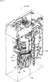
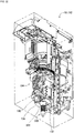
Fig. 3 is a perspective view showing a work head. -
Fig. 4 is a perspective view showing the work head. -
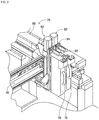
Fig. 5 is an enlarged sectional view of the work head. -
Fig. 6 is a transparent view of a gripping block. -
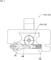
Fig. 7 is a sectional view taken along line AA inFig. 6 . -
Fig. 8 is a sectional view taken along line AA inFig. 6 . -
Fig. 9 is a sectional view taken along line BB inFig. 6 . -
Fig. 10 is a sectional view taken along line BB inFig. 6 . -
Fig. 11 is a perspective view showing a gripping claw. -
Fig. 12 is a perspective view showing a loading table. -
Fig. 13 is a perspective view showing the work head in a state in which the gripping claw is mounted. -
Fig. 14 is a perspective view showing the gripping claw and a pusher. -
Fig. 15 is a perspective view showing the work head in a state in which the gripping claw and the pusher are mounted. -
Fig. 16 is a view showing an axial component. -
Fig. 17 is a perspective view showing a component holding tool. -
Fig. 18 is a perspective view showing the component holding tool. -
Fig. 19 is a view showing a case in which the component holding tool is mounted on the work head. -
Fig. 20 is a perspective view showing the work head in a state in which the component holding tool is mounted. -
Fig. 21 is a perspective view showing a suction nozzle. -
Fig. 22 is a perspective view showing the work head in a state in which the suction nozzle is mounted. -
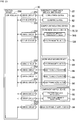
Fig. 23 is a block diagram showing a control device. - Hereinafter, as exemplary embodiments of the present invention, an embodiment of the present invention is described in detail with reference to the drawings.
-
Fig. 1 showscomponent mounting machine 10.Component mounting machine 10 is a device that performs a mounting work of a component tocircuit substrate 12.Component mounting machine 10 includes devicemain body 20, substrate conveyance andholding device 22,component supply device 24, bulkcomponent supply device 26,component mounting device 28, and control device 30 (seeFig. 23 ). Examples ofcircuit substrate 12 include a circuit board, a substrate which has a three-dimensional structure, and the like, and examples of the circuit board include a printed wiring board, a printed circuit board, and the like. - Device
main body 20 is configured byframe 40 and beam 42 suspended onframe 40. Substrate conveyance andholding device 22 is disposed at the center offrame 40 in the front-rear direction, and includesconveyance device 50 andclamping device 52.Conveyance device 50 is a device that conveyscircuit substrate 12, andclamping device 52 is a device that holdscircuit substrate 12. With this, substrate conveyance andholding device 22 conveyscircuit substrate 12 and fixedly holdscircuit substrate 12 at a predetermined position. In the following description, the conveyance direction ofcircuit substrate 12 is referred to as the X-direction, the horizontal direction perpendicular to the X-direction is referred to as the Y-direction, and the vertical direction is referred to as the Z-direction. -
Component supply device 24 is disposed at a first end portion offrame 40 in the front-rear direction.Component supply device 24 includes tray-typecomponent supply device 60 and feeder-type component supply device 62 (seeFig. 23 ). Tray-typecomponent supply device 60 is a device that supplies the component loaded on a tray. Feeder-typecomponent supply device 62 is a device that supplies the component by a tape feeder and a stick feeder (not illustrated). - Bulk
component supply device 26 is disposed at a second end portion offrame 40 in the front-rear direction. Bulkcomponent supply device 26 is a device that aligns multiple scattered components to supply the components in an aligned state. That is, bulk component supply device 32 is a device that aligns the multiple components in any orientation to a predetermined orientation to supply the components in the predetermined orientation. - Examples of the component supplied by
component supply device 24 and bulkcomponent supply device 26 include an electronic circuit component, components of a solar cell, components of a power module, and the like. Examples of the electronic circuit component include a component with leads, a component without leads, and the like. -
Component mounting device 28 is disposed on beam 42 and includes twowork heads head moving device 76. Workhead moving device 76 is configured byX-direction moving device 78, Y-direction moving device 80, and Z-direction moving device 82.X-direction moving device 78 and Y-direction moving device 80 haveelectromagnetic motors Fig. 23 ), and twowork heads frame 40 by the operation of each ofelectromagnetic motors direction moving device 82 haselectromagnetic motors 88 and 90 (seeFig. 23 ), andsliders electromagnetic motors work heads sliders sliders direction moving device 82. - Work heads 70 and 72 mount the component on
circuit substrate 12. As shown inFigs. 3 and4 , work heads 70 and 72 are each configured by headmain body 100, mountingsection 102, anddriving mechanism 104. Mountingsection 102 is a section on which a holding tool, a gripping claw, and the like described in detail below are mounted, and the holding tool, the gripping claw, and the like, which are mounted on mountingsection 102, hold the component by the driving ofdriving mechanism 104. - Specifically, as shown in
Fig. 5 ,driving mechanism 104 includesfirst shaft 110,second shaft 112,belt 114, pair ofnuts sliders First shaft 110 is held by headmain body 100 so as to be rotatable around the axial center in an orientation extending in the horizontal direction, and is controllably rotated by the driving of electromagnetic motor 126 (seeFig. 23 ).Second shaft 112 is held by headmain body 100 belowfirst shaft 110 so as to be rotatable around the axial center in an orientation parallel tofirst shaft 110.Belt 114 is wound around an end portion offirst shaft 110 and an end portion ofsecond shaft 112. As a result,second shaft 112 is also rotated in accordance with the rotation offirst shaft 110. - Pair of
nuts second shaft 112 in a separated state via a ball screw mechanism (not illustrated), and pair ofnuts main body 100 so as to be slidable along the axial direction ofsecond shaft 112. As a result, pair ofnuts second shaft 112. Pair ofsliders main body 100 so as to be slidable along the axial direction ofsecond shaft 112, and are fixed to pair ofnuts mechanism 104,first shaft 110 is rotated by the driving ofelectromagnetic motor 126, and pair ofsliders -
Flange section 127 is formed infirst shaft 110, andbrake pad 128 is disposed so as to faceflange section 127.Brake pad 128 is biased in a direction approachingflange section 127 by a compression coil spring (not illustrated), but is separated fromflange section 127 against the elastic force of the compression coil spring by the drive force ofelectromagnetic motor 126 when power is supplied toelectromagnetic motor 126. As a result, when power is supplied toelectromagnetic motor 126, the rotation offirst shaft 110, that is, the approach or separation of pair ofsliders electromagnetic motor 126 is cut off during a power failure or the like,brake pad 128 is pressed toflange section 127 by the elastic force of the compression coil spring. As a result, the approach or separation of pair ofsliders - Further, mounting
section 102 is configured by pair ofgripping blocks block 134. Pair of grippingblocks sliders blocks blocks sliders compression coil springs gripping grooves gripping blocks -
Connecting block 134 is disposed between pair ofgripping blocks Connecting block 134 has substantially the same shape as grippingblocks main body 100 so as to be slidable in the up-down direction via connectingpipe 146. Specifically, connectingpipe 146 is vertically fixed and arranged on an upper face of connectingblock 134, and connectingpipe 146 is inserted intoinsertion hole 148 open on a lower face of headmain body 100.Insertion hole 148 is open toward the space between pair ofgripping blocks main body 100, and by inserting connectingpipe 146 intoinsertion hole 148, connectingblock 134 extends between pair ofgripping blocks -
Connecting pipe 146 is biased downward bycompression coil spring 150 insideinsertion hole 148. The height of a lower face of connectingblock 134 biased to the downmost side bycompression coil spring 150 is the same as the height of lower faces of grippingblocks compression coil springs blocks block 134 are not biased upward, the heights of the lower faces of grippingblocks block 134 are the same. - In addition, connecting
block 134 is formed withfitting hole 160 open on the lower face. The inner diameter offitting hole 160 is increased toward the down side, and an inner wall surface which definesfitting hole 160 is a taper surface.Fitting hole 160 communicates with the inside of connectingpipe 146 at an upper end portion, andair supply pipe 162 is inserted intofitting hole 160 and connectingpipe 146.Air supply pipe 162 is held insidefitting hole 160 and connectingpipe 146 so as to be slidable in the up-down direction, and is biased downward bycompression coil spring 166.Air supply pipe 162 is connected to positive and negative pressure supply device 168 (seeFig. 23 ). The height of a lower face ofair supply pipe 162 biased to the downmost side bycompression coil spring 166 is higher than the height of a lower face of connectingblock 134 biased to the downmost side bycompression coil spring 150. That is, in a case in which connectingblock 134 andair supply pipe 162 are not biased upward, the lower face ofair supply pipe 162 is positioned insidefitting hole 160 of connectingblock 134. - Gripping
blocks fitting holes fitting hole 160 formed in connectingblock 134. Fixingmechanisms blocks fitting holes Fig. 6 , fixingmechanisms engaging body 178 and generally barrel-shapedstopper 180.Stopper 180 is held insidegripping block 130 so as to be slidable in the up-down direction on the side offitting holes hole 182 which penetrates the inside in the right-left direction is formed instopper 180.Stopper 180 is biased downward bycompression coil spring 184.Stopper 180 is held insideslide hole 185 formed ingripping blocks slide hole 185 is open in the lower faces of grippingblocks - On the other hand, engaging
body 178 is held insidegripping block 130 so as to be slidable in the right-left direction, into which throughhole 182 ofstopper 180 is inserted. A first end portion of engagingbody 178 which is held inside grippingblocks gripping block 130. In addition, a side face of engagingbody 178 between the second end portion and the center portion is slightly exposed from the inner wall surface offitting hole 170. Diameter-reducingsection 186 is formed in the vicinity of the center in the axial direction of engagingbody 178, and the dimension in the radial direction is reduced in diameter-reducingsection 186. -
Engaging body 178 is biased bycompression coil spring 188 in a direction extending from the side face ofgripping block 130. In a state in whichengaging body 178 is biased by the elastic force ofcompression coil spring 188, diameter-reducingsection 186 is not exposed on the inner wall surfaces offitting holes Fig. 7 , which is a sectional view taken along the line AA inFig. 6 , and a portion of engagingbody 178 other than diameter-reducingsection 186, that is, a portion which has a large dimension in the radial direction is exposed on the inner wall surfaces offitting holes body 178 slides toward the inside of grippingblocks compression coil spring 188, so that diameter-reducingsection 186 is exposed on the inner wall surfaces offitting holes Fig. 8 . In a state in which diameter-reducingsection 186 is exposed on the inner wall surfaces offitting holes section 186 does not protrude toward the inside from the inner wall surfaces offitting holes section 186 is in a state of being recessed from the inner wall surfaces offitting holes body 178 other than diameter-reducingsection 186 is exposed on the inner wall surfaces offitting holes fitting holes fitting holes - Further, as shown in
Fig. 6 , protrudingsection 190 which extends in a direction orthogonal to engagingbody 178 into which throughhole 182 is inserted is disposed in throughhole 182 ofstopper 180.Cutout section 192 is formed in engagingbody 178 so as to face protrudingsection 190 on the outer peripheral surface of the portion into which throughhole 182 is inserted. Therefore,stopper 180 is biased downward by the elastic force ofcompression coil spring 184, so that protrudingsection 190 engages withcutout section 192 of engagingbody 178 as shown inFig. 9 which is a sectional view taken along the line BB inFig. 6 . On the other hand,stopper 180 slides upward against the elastic force ofcompression coil spring 184, so that engagingbody 178, which is biased by the elastic force ofcompression coil spring 188, slides in a direction extending from the side face ofgripping block 130, and protrudingsection 190 disengages fromcutout section 192 of engagingbody 178 as shown inFig. 10 . In a state in which protrudingsection 190 engages withcutout section 192, that is, a state in whichstopper 180 is lowered by the elastic force ofcompression coil spring 184, engagingbody 178 slides toward the inside ofgripping block 130 against the elastic force ofcompression coil spring 188, and diameter-reducingsection 186 is exposed on the inner wall surface offitting hole 170. On the other hand, in a state in which protrudingsection 190 disengages fromcutout section 192, that is, a state in whichstopper 180 rises against the elastic force ofcompression coil spring 184, engagingbody 178 slides in a direction extending fromgripping block 130 by the elastic force ofcompression coil spring 188, and a portion other than diameter-reducingsection 186 is exposed on the inner wall surface offitting hole 170. - Gripping
claws Fig. 11 are mounted on grippingblocks mechanisms claws flange section 204,claw section 206 which extends downward fromflange section 204, and connectingsection 208 which extends upward fromflange section 204. A tip portion, that is, a lower end portion ofclaw section 206 is generally L-shaped, and is configured by grippingsection 210 which extends downward, andpressing section 212 which extends in a direction orthogonal togripping section 210 from the upper end ofgripping section 210. -
Connecting section 208 has a truncated cone shape, that is, a shape in which an apex portion of the cone is removed, and the dimension of connectingsection 208 in the radial direction is decreased toward the upper side. In addition, the overall dimension of connectingsection 208 in the radial direction is slightly smaller than the overall dimension offitting holes gripping blocks Engagement groove 216 which extends in the circumferential direction is formed on the outer peripheral surface of connectingsection 208.Convex section 218 which extends upward is formed on an upper face offlange section 204. The relative position of connectingsection 208 andconvex section 218 is the same as the relative position of the openings offitting holes slide hole 185 with respect to the lower faces of grippingblocks - Gripping
claws Fig. 12 . Loading table 220 is installed between substrate conveyance and holdingdevice 22 andcomponent supply device 24 on an upper face offrame 40 ofcomponent mounting machine 10. Multiple first placing holes 222 are formed in loading table 220. The inner dimension offirst placing hole 222 is larger than the outer dimension ofclaw section 206 ofgripping claws flange section 204 in the circumferential direction. Therefore, grippingclaws claw section 206 is inserted intofirst placing hole 222 andflange section 204 is latched on the edge portion which defines first placinghole 222. - Further, work heads 70 and 72 are moved above loading table 220 by the operation of work
head moving device 76 and are lowered. In this case, work heads 70 and 72 are lowered such that connectingsections 208 ofgripping claws fitting holes gripping blocks convex sections 218 ofgripping claws slide holes 185 ofgripping blocks sections 208 are inserted intofitting holes mechanisms stopper 180 is lowered, protrudingsection 190 engages withcutout section 192, and diameter-reducingsection 186 of engagingbody 178 is exposed on the inner wall surfaces offitting holes fitting holes section 186 is in a state of being recessed from the inner wall surfaces offitting holes sections 208 ofgripping claws fitting holes sections 208 are appropriately fitted intofitting holes body 178. - However, at the timing when connecting
sections 208 are fitted intofitting holes convex section 218 inserted intoslide hole 185 pressesstopper 180 upward, so that protrudingsection 190 disengages fromcutout section 192. Therefore, engagingbody 178 slides in a direction extending from grippingblocks compression coil spring 188, and a portion of engagingbody 178 other than diameter-reducingsection 186 is exposed on the inner wall surfaces offitting holes fitting holes body 178 other than diameter-reducingsection 186 is in a state of protruding from the inner wall surfaces offitting holes body 178 which protrudes from the inner wall surfaces offitting holes engagement groove 216 of connectingsection 208. As described above, connectingsections 208 ofgripping claws fitting holes gripping blocks body 178 which protrudes from the inner wall surfaces offitting holes engagement groove 216, so thatgripping claws blocks blocks - As shown in
Fig. 13 , grippingclaw 200 is mounted ongripping block 130, andgripping claw 202 is mounted ongripping block 132. In this case, pair ofgripping claws gripping blocks pressing sections 212 thereof face each other. As described above, by mountinggripping claws blocks gripping blocks driving mechanism 104, the component is gripped by grippingsections 210 of pair ofgripping claws circuit substrate 12, pair ofgripping blocks driving mechanism 104, so that the grip of the component by grippingsection 210 is released, and the component is mounted oncircuit substrate 12. In addition, in a case in which the component gripped by grippingsection 210 is mounted oncircuit substrate 12, the component can be pressed tocircuit substrate 12 by pressingsection 212. Since grippingblocks blocks - In a case in which the mounting work by gripping
claws claws head moving device 76, work heads 70 and 72 are moved above loading table 220, and work heads 70 and 72 are lowered such thatclaw section 206 ofgripping claw 200 is inserted intofirst placing hole 222. In this case, work heads 70 and 72 are lowered to a position in which the end portion of engagingbody 178 which extends from the side face ofgripping block 130 faces protrudingsection 224 erected on the edge portion which defines first placinghole 222. The operation of workhead moving device 76 is controlled such that the end portion of engagingbody 178 which extends from the side face ofgripping block 130contacts protruding section 224. As a result, the end portion of engagingbody 178 which extends from the side face ofgripping block 130 is moved toward protrudingsection 224, and is pressed to the inside of grippingblocks section 224. In this case, protrudingsection 190 ofstopper 180 engages withcutout section 192 of engagingbody 178, and diameter-reducingsection 186 of engagingbody 178 is exposed on the inner wall surfaces offitting holes body 178 disengages fromengagement groove 216 of connectingsection 208 ofgripping claws gripping claws blocks claws blocks component mounting machine 10, grippingclaws blocks - In a case in which gripping
claws body 178 which extends from the side face ofgripping block 130 is pressed to protrudingsection 224,gripping claw 200 may be loaded in a state of being biased to a position closer to protrudingsection 224 inside first placinghole 222. Therefore, pressingmember 226 which protrudes toward the inside offirst placing hole 222 is disposed below protrudingsection 224 at the edge portion which defines first placinghole 222. Pressingmember 226 is biased to the inside offirst placing hole 222 by the compression coil spring (not illustrated). As a result, grippingclaws hole 222 in a state of being biased to the position closer to protrudingsection 224 are pressed by pressingmember 226, so that the deviation of the placing positions ofgripping claws first placing hole 222 is canceled. - In addition, fixing mechanism 230 (see
Fig. 5 ) which has substantially the same structure as fixingmechanisms blocks block 134. Therefore, the description of fixingmechanism 230 will be omitted, and as the symbols of the constituent elements of fixingmechanisms body 178 and the like are used as the symbols of the constituent elements of fixingmechanism 230, that is, the engaging body and the like.Pusher 240 shown inFig. 14 is mounted on connectingblock 134 by usingfixing mechanism 230. - Specifically,
pusher 240 is configured byflange section 244,main body section 246 which extends downward fromflange section 244, and connectingsection 248 which extends upward fromflange section 244.Flange section 244 has the same shape asflange section 204 ofgripping claws convex section 250 is formed on the upper face offlange section 244 similarly toflange section 204.Connecting section 248 has the same shape as connectingsection 208 ofgripping claws engagement groove 251 which extends in the circumferential direction is formed on the outer peripheral surface of connectingsection 248 similarly to connectingsection 208. However, unlike connectingsection 208, connectingsection 248 is formed with throughhole 252 which penetrates in the up-down direction. Throughhole 252 also penetratesflange section 244 and reaches the inside ofmain body section 246. Insidemain body section 246, throughhole 252 communicates with an air chamber (not illustrated). A piston (not illustrated) is fitted into the air chamber so as to be slidable in the up-down direction.Rod 256 is fixed to the piston, androd 256 extends downward from the lower face ofmain body section 246. Pressingblock 258 is fixed to the lower end ofrod 256. The piston is biased upward by the elastic force of the coil spring insidemain body section 246. -
Pusher 240 which has such a structure is loaded onfirst placing hole 222 of loading table 220 similarly to grippingclaws section 248 ofpusher 240 is inserted intofitting hole 160 of connectingblock 134, andpusher 240 is mounted on connectingblock 134 via fixingmechanism 230. A method of mountingpusher 240 on connectingblock 134 is the same as a method of mountinggripping claws blocks head moving device 76 is controlled such that connectingsection 248 ofpusher 240 is inserted intofitting hole 160 of connectingblock 134, and theconvex section 250 ofpusher 240 is inserted intoslide hole 185 of connectingblock 134. As a result, connectingsection 248 ofpusher 240 is fitted intofitting hole 160 of connectingblock 134, and engagingbody 178 of fixingmechanism 230 engages withengagement groove 216 insidefitting hole 160, so thatpusher 240 is mounted on connectingblock 134 in a state in which falling off from connectingblock 134 is prevented. - However, in connecting
block 134, unlike grippingblocks pusher 240 mounted on connectingblock 134 communicates withair supply pipe 162 insidefitting hole 160. Specifically, by inserting connectingsection 248 ofpusher 240 intofitting hole 160, an upper face of connectingsection 248 contacts the lower face ofair supply pipe 162. Sinceair supply pipe 162 is biased downward bycompression coil spring 166 as described above,air supply pipe 162 is pressed upward by connectingsection 248 by inserting connectingsection 248 intofitting hole 160. As a result, throughhole 252 open on the upper face of connectingsection 248 communicates withair supply pipe 162 in a state in which throughhole 252 is in close contact withair supply pipe 162. - As described above, through
hole 252 of connectingsection 248 communicates withair supply pipe 162, so thatpusher 240 mounted on connectingblock 134 is operated. That is, in a case in which a positive pressure is supplied toair supply pipe 162 from positive and negativepressure supply device 168, the piston is lowered inside the air chamber, andpressing block 258 is lowered together withrod 256. Further, in a case in whichair supply pipe 162 is opened to the atmosphere by positive and negativepressure supply device 168, the piston rises inside the air chamber by the elastic force of the coil spring. As a result, pressing block 258 rises together withrod 256. - Further, in a case in which pusher 240 is mounted on connecting
block 134, grippingclaws Fig. 14 are mounted on grippingblocks claws flange section 264,claw section 266, and connectingsection 268 similarly to grippingclaws Flange section 264 and connectingsection 268 have the same shapes asflange section 204 and connectingsection 208 ofgripping claws claw section 266 is configured by only grippingsection 270 which extends downward, unlikeclaw section 206 ofgripping claws Gripping groove 272 which extends in the up-down direction is formed on a side face ofgripping section 270. Grippingclaws first placing hole 222 of loading table 220 and mounted on grippingblocks claws gripping claws blocks gripping claws blocks - Incidentally, as shown in
Fig. 15 , grippingclaw 260 is mounted ongripping block 130, andgripping claw 262 is mounted ongripping block 132. In this case, pair ofgripping claws gripping blocks gripping grooves 272 thereof face each other. As described above, grippingclaws blocks pusher 240 is mounted on connectingblock 134, so that the mounting work of the axial component is performed bywork head 70. - Specifically, as shown in
Fig. 16 ,axial component 280 is configured by componentmain body 282 and pair oflead wires 284. Componentmain body 282 has a generally cylindrical shape, and pair oflead wires 284 each extend in opposite directions from both end faces of componentmain body 282. Pair oflead wires 284 are bent in the same direction at a generally right angle, and a tip portion of eachlead wire 284 isbent portion 286. Inwork head 70, beforeaxial component 280 is held, the operation of drivingmechanism 104 is controlled, and the distance betweengripping sections 270 of pair ofgripping claws bent portions 286 of pair oflead wires 284 ofaxial component 280.Axial component 280 is supplied in an orientation ofaxial component 280 shown inFig. 16 , that is, an orientation in whichbent portions 286 is directed to the down side in feeder-typecomponent supply device 62 or the like. - Further,
work head 70 is lowered at a supply position ofaxial component 280, so thatbent portions 286 of pair oflead wires 284 ofaxial component 280 are press-fitted intogripping grooves 272 formed in grippingsections 270 of pair ofgripping claws axial component 280 is gripped by grippingclaws head moving device 76 is controlled such thatbent portion 286 ofaxial component 280 gripped by grippingclaws circuit substrate 12. Next,bent portion 286 is inserted into the through hole,pusher 240 is operated by the supply of the positive pressure toair supply pipe 162, andpressing block 258 is lowered. As a result,axial component 280 gripped by grippingsection 270 of pair ofgripping claws block 258, is separated from grippingclaws circuit substrate 12. - Then, in a case in which the mounting work of
axial component 280 by grippingclaws pusher 240 is completed, grippingclaws pusher 240 are returned to loading table 220. A method of returninggripping claws pusher 240 to loading table 220 is the same as a method of returninggripping claws body 178 which extends from the side faces of grippingblocks block 134 by protrudingsection 224 of loading table 220, engagingbody 178 disengages from connectingsections fitting holes claws pusher 240 are separated from grippingblocks block 134, and are returned tofirst placing hole 222 of loading table 220. As described above, grippingclaws pusher 240 are also automatically mounted on and separated from grippingblocks block 134. Grippingclaws pusher 240 returned tofirst placing hole 222 are also pressed by pressingmember 226 similarly to grippingclaws gripping claws pusher 240 infirst placing hole 222 is canceled. - In addition, as described above, gripping
claws section 102 of work heads 70 and 72 by inserting connectingsections 208 ofgripping claws fitting holes gripping blocks blocks Component holding tool 290 gripsradial component 292, and as shown inFigs. 17 and18 , is configured byflange section 296 and holding sectionmain body 298 which is fixed to a lower face offlange section 296.Component holding tool 290 is disclosed inJapanese Patent Application No. 2017-551441 - Holding section
main body 298 includesmain body section 300, pair ofclaw sections 302, andauxiliary plate 304. Pair ofclaw sections 302 are swingly held bymain body section 300.Auxiliary plate 304 is positioned between pair ofclaw sections 302 and swings together with pair ofclaw sections 302. In this case,auxiliary plate 304 enters between pair oflead wires 306 ofradial component 292. Further, pair ofclaw sections 302 approachauxiliary plate 304, so that pair oflead wires 306 are interposed by pair ofclaw sections 302 andauxiliary plate 304. The air chamber (not illustrated) is formed insidemain body section 300, and the piston (not illustrated) is fitted into the air chamber so as to be slidable in the up-down direction. The piston, pair ofclaw sections 302, andauxiliary plate 304 are connected by a conversion mechanism (not illustrated). The conversion mechanism converts the movement of the piston in the up-down direction into the swing of pair ofclaw sections 302 andauxiliary plate 304. Further, throughhole 308 which penetrates in the up-down direction is formed inflange section 296, and throughhole 308 communicates with the air chamber formed inmain body section 300 of holding sectionmain body 298. With such a structure, air is supplied to the air chamber via connectingsection 208, and pair ofclaw sections 302 andauxiliary plate 304 swing. A pair of opposing side edges offlange section 296 are generally straight, and pair of grippedsections 310 are formed on the pair of side edges. - Further, as shown in
Fig. 12 ,second placing hole 228 is formed in loading table 220 in addition tofirst placing hole 222. The inner dimension ofsecond placing hole 228 is larger than the outer dimension of holding sectionmain body 298 ofcomponent holding tool 290 in the circumferential direction, and is smaller than the outer dimension offlange section 296 in the circumferential direction. Therefore,component holding tool 290 is loaded on loading table 220 in a state in which holding sectionmain body 298 is inserted intosecond placing hole 228 andflange section 296 is latched on the edge portion which defines second placinghole 228. - Further, work heads 70 and 72 are moved above loading table 220 by the operation of work
head moving device 76 and are lowered. Before work heads 70 and 72 are lowered, the distance between pair ofgripping blocks sections 310 offlange section 296 ofcomponent holding tool 290 by the operation of drivingmechanism 104. Then, work heads 70 and 72 are lowered such thatflange section 296 ofcomponent holding tool 290 loaded on loading table 220 enters between pair ofgripping blocks Flange section 296 enters between pair ofgripping blocks sections 310 formed onflange section 296 face pair ofgripping blocks - In this case, the lower face of connecting
block 134 contacts the upper face offlange section 296 entering between pair ofgripping blocks block 134 rises by being pressed upward byflange section 296 as shown inFig. 19 . As a result, throughhole 308 open on the upper face offlange section 296 communicates withair supply pipe 162 in a state in which throughhole 308 is in close contact withair supply pipe 162 insidefitting hole 160 of connectingblock 134. In a state in which throughhole 308 communicates withair supply pipe 162, grippedsection 310 offlange section 296 andgripping grooves 140 ofgripping blocks driving mechanism 104, pair ofgripping blocks sections 310 are interposed by pair ofgripping grooves 140. As a result, as shown inFig. 20 ,component holding tool 290 is gripped by grippingblocks flange section 296. That is,flange section 296 is gripped by grippingblocks air supply pipe 162 communicates with throughhole 308 ofcomponent holding tool 290, so thatcomponent holding tool 290 is mounted on mountingsection 102 of work heads 70 and 72. - As described above, by mounting
component holding tool 290 on mountingsection 102, the mounting work ofradial component 292 is performed by work heads 70 and 72. That is, for example, by the supply of the positive pressure toair supply pipe 162,lead wire 306 swings toward the space between pair oflead wires 306 ofradial component 292, and pair ofclaw sections 302 swing in a direction approachingauxiliary plate 304. As a result, pair oflead wires 306 are interposed by pair ofclaw sections 302 andauxiliary plate 304.Lead wire 306 interposed byclaw sections 302 andauxiliary plate 304 is inserted into the through hole (not illustrated) formed incircuit substrate 12. Next, in a case in which leadwire 306 is inserted into the through hole, by the supply of a negative pressure toair supply pipe 162,lead wire 306 swings in a direction of being pulled out from between pair oflead wires 306, and pair ofclaw sections 302 swings in a direction of being separated fromauxiliary plate 304. As a result,radial component 292 is separated fromcomponent holding tool 290 and mounted oncircuit substrate 12. - Then, in a case in which the mounting work of
radial component 292 bycomponent holding tool 290 is completed,component holding tool 290 is returned to loading table 220. Specifically, by the operation of workhead moving device 76, work heads 70 and 72 are moved above loading table 220, and work heads 70 and 72 are lowered such that holding sectionmain body 298 ofcomponent holding tool 290 is inserted intosecond placing hole 228. Then, pair ofgripping blocks driving mechanism 104, the gripping ofcomponent holding tool 290 by grippingblocks component holding tool 290 is separated from grippingblocks component holding tool 290 is separated from grippingblocks component holding tool 290 is also separated from connectingblock 134. As a result,component holding tool 290 is returned to loading table 220. As described above,component holding tool 290 is also automatically mounted on and separated from grippingblocks block 134. - In addition,
suction nozzle 320 shown inFig. 21 can also be mounted on mountingsection 102.Suction nozzle 320 is configured byflange section 322 and nozzlemain body 324 fixed to the lower face offlange section 322.Flange section 322 has the same shape asflange section 296 ofcomponent holding tool 290, and similarly toflange section 296, pair of grippedsections 326 are formed on a pair of opposing side edges offlange section 322, and throughhole 328 which penetratesflange section 322 in the up-down direction is formed. Nozzlemain body 324 includesmain body section 330 which has a generally cylindrical shape, andsuction pipe 332 through whichmain body section 330 is inserted in the up-down direction. The upper end ofsuction pipe 332 communicates with the lower end of throughhole 328 formed inflange section 322. -
Suction nozzle 320 which has such a structure is also mounted on work heads 70 and 72 in the same manner ascomponent holding tool 290. That is, in a state in whichair supply pipe 162 communicates with throughhole 328 ofsuction nozzle 320, pair of grippedsections 326 offlange section 322 are interposed by grippinggrooves 140 of pair ofgripping blocks Fig. 22 ,component holding tool 290 is mounted on mountingsection 102 of work heads 70 and 72. Then, the mounting work of the component is performed by work heads 70 and 72. That is, by the supply of the negative pressure toair supply pipe 162, the component is picked up and held at a tip end ofsuction pipe 332. Then, in a state in which the component is loaded on the predetermined position ofcircuit substrate 12, by the supply of the positive pressure toair supply pipe 162, the component is separated from the tip end ofsuction pipe 332 and the component is mounted oncircuit substrate 12. - Then, in a case in which the mounting work by
suction nozzle 320 is completed,suction nozzle 320 is returned to loading table 220. A method of returningsuction nozzle 320 to loading table 220 is the same as a method of returningcomponent holding tool 290 to loading table 220. That is, by the driving ofdriving mechanism 104, pair ofgripping blocks suction nozzle 320 is separated from grippingblocks block 134, and is returned to loading table 220. As described above,suction nozzle 320 is also automatically mounted on and separated from grippingblocks block 134. - As described above, on mounting
section 102 of work heads 70 and 72, any of the four types of holding tools ofgripping claws pusher 240 andgripping claws component holding tool 290, andsuction nozzle 320, which hold the component, is mounted. As a result, the mounting works of various components can be performed incomponent mounting machine 10. - In particular, in gripping
claws pusher 240, connectingsection section 102 by being inserted intofitting holes gripping blocks block 134. On the other hand, incomponent holding tool 290 andsuction nozzle 320,flange sections section 102 by being gripped by pair ofgripping blocks section 102 by two different methods of insertion of connectingsection fitting holes flange section 296 by grippingblocks gripping claws sections component holding tool 290 havingflange sections section 102 of work heads 70 and 72. - The four types of holding tools are automatically mounted on and separated from mounting
section 102 on loading table 220. As a result, the burden on the operator is reduced. Furthermore, the rotation offirst shaft 110 of drivingmechanism 104 is inhibited bybrake pad 128 during a power failure or the like. Therefore, the positions of pair ofgripping blocks claws blocks claws component holding tool 290 orsuction nozzle 320 is gripped by grippingblocks component holding tool 290 orsuction nozzle 320 gripped by grippingblocks component holding tool 290 orsuction nozzle 320 from falling off during a power failure. -
Control device 30 that controls the operations of work heads 70 and 72, workhead moving device 76, and the like includescontroller 350 andmultiple drive circuits 352, as shown inFig. 23 .Multiple drive circuits 352 are connected toconveyance device 50, clampingdevice 52,electromagnetic motors pressure supply device 168, tray-typecomponent supply device 60, feeder-typecomponent supply device 62, and bulkcomponent supply device 26.Controller 350 includes CPU, ROM, RAM, and the like, which is mainly a computer, and is connected tomultiple drive circuits 352. As a result, the operations of substrate conveyance and holdingdevice 22,component supply device 24, and the like are controlled bycontroller 350. -
Component mounting machine 10 in the above embodiment is an example of a work machine.Control device 30 is an example of a control device. Work heads 70 and 72 are examples of a work head. Workhead moving device 76 is an example of a moving device. Headmain body 100 is an example of a head main body. Grippingblocks Air supply pipe 162 is an example of an air passage. Fixingmechanisms Engaging body 178 is an example of an engaging body. Grippingclaws Protruding section 224 is an example of an abutting section.Fixing mechanism 230 is an example of a connecting mechanism.Pusher 240 is an example of a pusher. Grippingclaws Component holding tool 290 is an example of a holding tool.Suction nozzle 320 is another example of the holding tool. - The present invention is not limited to the embodiment described above, and can be implemented in various embodiments with various modifications and improvements based on the knowledge of those skilled in the art. Specifically, for example, in the above embodiment,
pusher 240 is mounted infitting hole 160 of connectingblock 134, but a work tool that performs the operation different frompusher 240 may be mounted infitting hole 160. For example, a work tool that blows air from the work tool by supply of air fromair supply pipe 162 to perform cleaning or the like may be mounted infitting hole 160. - In the above embodiment,
air supply pipe 162 is disposed only infitting hole 160 of connectingblock 134, butair supply pipe 162 may be disposed infitting holes gripping blocks hole 252 formed inpusher 240, in connectingsection gripping claws claws - In fixing
mechanisms body 178 slides to engage with connectingsections gripping claws body 178 may be moved in various manners such as swinging, pivoting, and rotating to engage with connectingsections gripping claws - 10: component mounting machine (work machine), 30: control device, 70: work head, 72: work head, 76: work head moving device (moving device), 100: head main body, 130: gripping block (movable body), 132: gripping block (movable body), 162: air supply pipe (air passage), 174: fixing mechanism, 176: fixing mechanism, 178: engaging body, 200: gripping claw (claw), 202: gripping claw (claw), 220: loading table (accommodation section), 224: protruding section (abutting section), 230: fixing mechanism (connecting mechanism), 240: pusher, 260: gripping claw (claw), 262: gripping claw (claw), 290: component holding tool (holding tool), 320: suction nozzle (holding tool)
Claims (4)
- A work head comprising:a head main body;multiple movable bodies held to be approachable to or separatable from each other by the head main body; andan air passage formed, , being open between the multiple movable bodies, in the head main body,wherein the work head grips a holding tool, being configured to hold a component, by causing the multiple movable bodies to approach the holding tool to be communicated with the air passage, so that the holding tool holds the component by air supplied thereto via the air passage.
- The work head according to claim 1, wherein by fixing two or more claws to two or more movable bodies among the multiple movable bodies via a fixing mechanism, the component is gripped by the two or more claws.
- The work head according to claim 2, wherein by connecting a pusher to the air passage via a connecting mechanism in a state in which the two or more claws are fixed to the two or more movable bodies, the component is pressed between the two or more claws by supply of air to the pusher via the air passage.
- A work machine comprising:the work head according to claim 2 or 3;a moving device configured to move the work head;a control device configured to control operation of the moving device; andan accommodation section configured to accommodate the claws,wherein the fixing mechanism includes an engaging body configured to move between an engaging position with the claws and a disengaging position from the claws, and is configured to fix the claws by engagement of the engaging body with the claws and separate the claws by disengagement, andby controlling the operation of the moving device by the control device such that the engaging body abuts on an abutting section formed in the accommodation section in a state in which the claws are fixed to the movable bodies, the engaging body is moved from the engaging position with the claws to the disengaging position from the claws, the claws are separated from the movable bodies, and the claws are accommodated in the accommodation section.
Applications Claiming Priority (1)
| Application Number | Priority Date | Filing Date | Title |
|---|---|---|---|
| PCT/JP2018/048455 WO2020136869A1 (en) | 2018-12-28 | 2018-12-28 | Work head and work machine |
Publications (3)
| Publication Number | Publication Date |
|---|---|
| EP3905873A1 true EP3905873A1 (en) | 2021-11-03 |
| EP3905873A4 EP3905873A4 (en) | 2022-01-05 |
| EP3905873B1 EP3905873B1 (en) | 2024-06-26 |
Family
ID=71126196
Family Applications (1)
| Application Number | Title | Priority Date | Filing Date |
|---|---|---|---|
| EP18944757.6A Active EP3905873B1 (en) | 2018-12-28 | 2018-12-28 | Work head and work machine |
Country Status (5)
| Country | Link |
|---|---|
| US (1) | US12179340B2 (en) |
| EP (1) | EP3905873B1 (en) |
| JP (1) | JP7121143B2 (en) |
| CN (1) | CN113170608B (en) |
| WO (1) | WO2020136869A1 (en) |
Family Cites Families (24)
| Publication number | Priority date | Publication date | Assignee | Title |
|---|---|---|---|---|
| JPS63236400A (en) * | 1987-03-13 | 1988-10-03 | エヌ・ベー・フィリップス・フルーイランペンファブリケン | Holder |
| JPH0329117Y2 (en) * | 1987-11-06 | 1991-06-21 | ||
| JP2808851B2 (en) | 1990-07-25 | 1998-10-08 | 松下電器産業株式会社 | Head device for transferring electronic components |
| US5529359A (en) * | 1994-04-22 | 1996-06-25 | Borcea; Nicky | Cripper assembly with improved synchronous transmission |
| US5562320A (en) * | 1994-11-04 | 1996-10-08 | International Business Machines Corporation | Gripper head |
| IT1300571B1 (en) * | 1998-04-20 | 2000-05-23 | Gimatic Spa | PARALLEL PNEUMATIC CLAMP WITH BODY AND JAWS OBTAINED FROM EXTRUDED ELEMENTS |
| US6015174A (en) * | 1998-06-04 | 2000-01-18 | Eastman Kodak Company | Universal end effector for robotic applications |
| JP2000124679A (en) * | 1998-10-13 | 2000-04-28 | Sanyo Electric Co Ltd | Automatic electronic component-mounting device |
| JP2000261194A (en) * | 1999-03-05 | 2000-09-22 | Matsushita Electric Ind Co Ltd | Electronic component mounting apparatus and mounting method, and clamp head for electronic component pickup |
| KR100371226B1 (en) * | 2000-12-13 | 2003-02-06 | 미래산업 주식회사 | Gripper for Component Having Different Shape in Surface Mount Device |
| JP2002200585A (en) * | 2000-12-28 | 2002-07-16 | Fuji Mach Mfg Co Ltd | Device for holding electrical component |
| JP4353135B2 (en) * | 2005-05-13 | 2009-10-28 | パナソニック株式会社 | Nozzle mounting jig and nozzle mounting method |
| ITBS20050156A1 (en) * | 2005-12-13 | 2007-06-14 | Gimatic Spa | PERFECTED PARALLEL CALIPER CALIPER |
| JP4969609B2 (en) | 2009-06-09 | 2012-07-04 | 富士機械製造株式会社 | Electric component holding device |
| US9677588B2 (en) * | 2012-01-20 | 2017-06-13 | Fuji Machine Mfg. Co., Ltd. | Component mounter mounting head holding device |
| CN106879245A (en) * | 2012-02-08 | 2017-06-20 | Juki株式会社 | Electronic component mounting apparatus, electronic component mounting system and electronic component mounting method |
| WO2013140571A1 (en) * | 2012-03-22 | 2013-09-26 | 富士機械製造株式会社 | Chuck device |
| US20150237773A1 (en) | 2012-08-31 | 2015-08-20 | Fuji Machine Mfg. Co., Ltd. | Component mounter |
| WO2015136600A1 (en) * | 2014-03-10 | 2015-09-17 | 富士機械製造株式会社 | Tape feeder |
| JP6534016B2 (en) * | 2017-03-06 | 2019-06-26 | パナソニックIpマネジメント株式会社 | Component mounting apparatus and component mounting method |
| JP6551805B2 (en) | 2017-03-06 | 2019-07-31 | パナソニックIpマネジメント株式会社 | Component mounting apparatus and component mounting method |
| JP6914475B2 (en) * | 2017-05-18 | 2021-08-04 | Smc株式会社 | Work gripping device |
| WO2018237333A1 (en) * | 2017-06-22 | 2018-12-27 | Zitting Gordon T | ROBOT PREVENTION DEVICE |
| US20210178609A1 (en) * | 2019-12-11 | 2021-06-17 | Ati Industrial Automation, Inc. | Gripping Device for Use with a Robot |
-
2018
- 2018-12-28 JP JP2020562268A patent/JP7121143B2/en active Active
- 2018-12-28 EP EP18944757.6A patent/EP3905873B1/en active Active
- 2018-12-28 WO PCT/JP2018/048455 patent/WO2020136869A1/en not_active Ceased
- 2018-12-28 US US17/418,650 patent/US12179340B2/en active Active
- 2018-12-28 CN CN201880099768.5A patent/CN113170608B/en active Active
Also Published As
| Publication number | Publication date |
|---|---|
| EP3905873A4 (en) | 2022-01-05 |
| JP7121143B2 (en) | 2022-08-17 |
| US12179340B2 (en) | 2024-12-31 |
| CN113170608A (en) | 2021-07-23 |
| EP3905873B1 (en) | 2024-06-26 |
| US20220072720A1 (en) | 2022-03-10 |
| WO2020136869A1 (en) | 2020-07-02 |
| JPWO2020136869A1 (en) | 2021-09-09 |
| CN113170608B (en) | 2022-09-06 |
Similar Documents
| Publication | Publication Date | Title |
|---|---|---|
| US6513233B1 (en) | Component mounting method and apparatus | |
| US9992918B2 (en) | Method for mounting electronic component | |
| JP2020089959A (en) | Hand, robot system, and workpiece taking-out method | |
| CN104640433B (en) | The device and method of electronic component are installed | |
| US20170304968A1 (en) | Robot screw-fastening device and screw-fastening robot system | |
| JP5878083B2 (en) | Clinch pin, component mounting device | |
| JP2017127940A (en) | Robot equipment | |
| US11202374B2 (en) | Method of mounting component | |
| WO2016017029A1 (en) | Component mounting method and component mounting device | |
| JP2008221438A (en) | Robot hand and robot | |
| JP2013258192A (en) | Clinch device and component mounting device | |
| US12179340B2 (en) | Work head and work machine | |
| WO2018216147A1 (en) | Component gripping tool | |
| JP6130504B2 (en) | Component mounter | |
| CN111170005B (en) | Loading and unloading device | |
| JPWO2005081611A1 (en) | Support pin gripping device and substrate supporting device | |
| CN112828579A (en) | High-precision automatic screw machine | |
| JP7300040B2 (en) | working head | |
| JP7563884B2 (en) | Component placement device | |
| JP5292254B2 (en) | Terminal alignment apparatus and terminal alignment method | |
| JP6590645B2 (en) | Lead terminal insertion failure detection device and component mounting device | |
| JP5878082B2 (en) | Clinch device, component mounting device | |
| CN209922359U (en) | Automatic loading and unloading equipment | |
| CN218657986U (en) | Feeding and discharging device for numerical control machining equipment and numerical control machining equipment | |
| CN115394587B (en) | Automatic terminal riveting machine and terminal riveting method |
Legal Events
| Date | Code | Title | Description |
|---|---|---|---|
| STAA | Information on the status of an ep patent application or granted ep patent |
Free format text: STATUS: THE INTERNATIONAL PUBLICATION HAS BEEN MADE |
|
| PUAI | Public reference made under article 153(3) epc to a published international application that has entered the european phase |
Free format text: ORIGINAL CODE: 0009012 |
|
| STAA | Information on the status of an ep patent application or granted ep patent |
Free format text: STATUS: REQUEST FOR EXAMINATION WAS MADE |
|
| 17P | Request for examination filed |
Effective date: 20210616 |
|
| AK | Designated contracting states |
Kind code of ref document: A1 Designated state(s): AL AT BE BG CH CY CZ DE DK EE ES FI FR GB GR HR HU IE IS IT LI LT LU LV MC MK MT NL NO PL PT RO RS SE SI SK SM TR |
|
| A4 | Supplementary search report drawn up and despatched |
Effective date: 20211206 |
|
| RIC1 | Information provided on ipc code assigned before grant |
Ipc: B25J 15/08 20060101ALI20211130BHEP Ipc: B25J 15/06 20060101ALI20211130BHEP Ipc: H05K 13/04 20060101AFI20211130BHEP |
|
| DAV | Request for validation of the european patent (deleted) | ||
| DAX | Request for extension of the european patent (deleted) | ||
| P01 | Opt-out of the competence of the unified patent court (upc) registered |
Effective date: 20230328 |
|
| GRAP | Despatch of communication of intention to grant a patent |
Free format text: ORIGINAL CODE: EPIDOSNIGR1 |
|
| STAA | Information on the status of an ep patent application or granted ep patent |
Free format text: STATUS: GRANT OF PATENT IS INTENDED |
|
| INTG | Intention to grant announced |
Effective date: 20240202 |
|
| GRAS | Grant fee paid |
Free format text: ORIGINAL CODE: EPIDOSNIGR3 |
|
| GRAA | (expected) grant |
Free format text: ORIGINAL CODE: 0009210 |
|
| STAA | Information on the status of an ep patent application or granted ep patent |
Free format text: STATUS: THE PATENT HAS BEEN GRANTED |
|
| AK | Designated contracting states |
Kind code of ref document: B1 Designated state(s): AL AT BE BG CH CY CZ DE DK EE ES FI FR GB GR HR HU IE IS IT LI LT LU LV MC MK MT NL NO PL PT RO RS SE SI SK SM TR |
|
| REG | Reference to a national code |
Ref country code: GB Ref legal event code: FG4D |
|
| REG | Reference to a national code |
Ref country code: CH Ref legal event code: EP |
|
| REG | Reference to a national code |
Ref country code: DE Ref legal event code: R096 Ref document number: 602018071175 Country of ref document: DE |
|
| PG25 | Lapsed in a contracting state [announced via postgrant information from national office to epo] |
Ref country code: BG Free format text: LAPSE BECAUSE OF FAILURE TO SUBMIT A TRANSLATION OF THE DESCRIPTION OR TO PAY THE FEE WITHIN THE PRESCRIBED TIME-LIMIT Effective date: 20240626 |
|
| PG25 | Lapsed in a contracting state [announced via postgrant information from national office to epo] |
Ref country code: HR Free format text: LAPSE BECAUSE OF FAILURE TO SUBMIT A TRANSLATION OF THE DESCRIPTION OR TO PAY THE FEE WITHIN THE PRESCRIBED TIME-LIMIT Effective date: 20240626 Ref country code: FI Free format text: LAPSE BECAUSE OF FAILURE TO SUBMIT A TRANSLATION OF THE DESCRIPTION OR TO PAY THE FEE WITHIN THE PRESCRIBED TIME-LIMIT Effective date: 20240626 |
|
| REG | Reference to a national code |
Ref country code: LT Ref legal event code: MG9D |
|
| PG25 | Lapsed in a contracting state [announced via postgrant information from national office to epo] |
Ref country code: GR Free format text: LAPSE BECAUSE OF FAILURE TO SUBMIT A TRANSLATION OF THE DESCRIPTION OR TO PAY THE FEE WITHIN THE PRESCRIBED TIME-LIMIT Effective date: 20240927 |
|
| PG25 | Lapsed in a contracting state [announced via postgrant information from national office to epo] |
Ref country code: LV Free format text: LAPSE BECAUSE OF FAILURE TO SUBMIT A TRANSLATION OF THE DESCRIPTION OR TO PAY THE FEE WITHIN THE PRESCRIBED TIME-LIMIT Effective date: 20240626 |
|
| REG | Reference to a national code |
Ref country code: NL Ref legal event code: MP Effective date: 20240626 |
|
| PG25 | Lapsed in a contracting state [announced via postgrant information from national office to epo] |
Ref country code: NO Free format text: LAPSE BECAUSE OF FAILURE TO SUBMIT A TRANSLATION OF THE DESCRIPTION OR TO PAY THE FEE WITHIN THE PRESCRIBED TIME-LIMIT Effective date: 20240926 Ref country code: LV Free format text: LAPSE BECAUSE OF FAILURE TO SUBMIT A TRANSLATION OF THE DESCRIPTION OR TO PAY THE FEE WITHIN THE PRESCRIBED TIME-LIMIT Effective date: 20240626 Ref country code: HR Free format text: LAPSE BECAUSE OF FAILURE TO SUBMIT A TRANSLATION OF THE DESCRIPTION OR TO PAY THE FEE WITHIN THE PRESCRIBED TIME-LIMIT Effective date: 20240626 Ref country code: GR Free format text: LAPSE BECAUSE OF FAILURE TO SUBMIT A TRANSLATION OF THE DESCRIPTION OR TO PAY THE FEE WITHIN THE PRESCRIBED TIME-LIMIT Effective date: 20240927 Ref country code: FI Free format text: LAPSE BECAUSE OF FAILURE TO SUBMIT A TRANSLATION OF THE DESCRIPTION OR TO PAY THE FEE WITHIN THE PRESCRIBED TIME-LIMIT Effective date: 20240626 Ref country code: BG Free format text: LAPSE BECAUSE OF FAILURE TO SUBMIT A TRANSLATION OF THE DESCRIPTION OR TO PAY THE FEE WITHIN THE PRESCRIBED TIME-LIMIT Effective date: 20240626 Ref country code: RS Free format text: LAPSE BECAUSE OF FAILURE TO SUBMIT A TRANSLATION OF THE DESCRIPTION OR TO PAY THE FEE WITHIN THE PRESCRIBED TIME-LIMIT Effective date: 20240926 |
|
| PG25 | Lapsed in a contracting state [announced via postgrant information from national office to epo] |
Ref country code: NL Free format text: LAPSE BECAUSE OF FAILURE TO SUBMIT A TRANSLATION OF THE DESCRIPTION OR TO PAY THE FEE WITHIN THE PRESCRIBED TIME-LIMIT Effective date: 20240626 |
|
| REG | Reference to a national code |
Ref country code: AT Ref legal event code: MK05 Ref document number: 1698774 Country of ref document: AT Kind code of ref document: T Effective date: 20240626 |
|
| PG25 | Lapsed in a contracting state [announced via postgrant information from national office to epo] |
Ref country code: NL Free format text: LAPSE BECAUSE OF FAILURE TO SUBMIT A TRANSLATION OF THE DESCRIPTION OR TO PAY THE FEE WITHIN THE PRESCRIBED TIME-LIMIT Effective date: 20240626 |
|
| PG25 | Lapsed in a contracting state [announced via postgrant information from national office to epo] |
Ref country code: PT Free format text: LAPSE BECAUSE OF FAILURE TO SUBMIT A TRANSLATION OF THE DESCRIPTION OR TO PAY THE FEE WITHIN THE PRESCRIBED TIME-LIMIT Effective date: 20241028 |
|
| PG25 | Lapsed in a contracting state [announced via postgrant information from national office to epo] |
Ref country code: PT Free format text: LAPSE BECAUSE OF FAILURE TO SUBMIT A TRANSLATION OF THE DESCRIPTION OR TO PAY THE FEE WITHIN THE PRESCRIBED TIME-LIMIT Effective date: 20241028 |
|
| PG25 | Lapsed in a contracting state [announced via postgrant information from national office to epo] |
Ref country code: PL Free format text: LAPSE BECAUSE OF FAILURE TO SUBMIT A TRANSLATION OF THE DESCRIPTION OR TO PAY THE FEE WITHIN THE PRESCRIBED TIME-LIMIT Effective date: 20240626 |
|
| PG25 | Lapsed in a contracting state [announced via postgrant information from national office to epo] |
Ref country code: EE Free format text: LAPSE BECAUSE OF FAILURE TO SUBMIT A TRANSLATION OF THE DESCRIPTION OR TO PAY THE FEE WITHIN THE PRESCRIBED TIME-LIMIT Effective date: 20240626 |
|
| PG25 | Lapsed in a contracting state [announced via postgrant information from national office to epo] |
Ref country code: AT Free format text: LAPSE BECAUSE OF FAILURE TO SUBMIT A TRANSLATION OF THE DESCRIPTION OR TO PAY THE FEE WITHIN THE PRESCRIBED TIME-LIMIT Effective date: 20240626 Ref country code: IS Free format text: LAPSE BECAUSE OF FAILURE TO SUBMIT A TRANSLATION OF THE DESCRIPTION OR TO PAY THE FEE WITHIN THE PRESCRIBED TIME-LIMIT Effective date: 20241026 |
|
| PG25 | Lapsed in a contracting state [announced via postgrant information from national office to epo] |
Ref country code: CZ Free format text: LAPSE BECAUSE OF FAILURE TO SUBMIT A TRANSLATION OF THE DESCRIPTION OR TO PAY THE FEE WITHIN THE PRESCRIBED TIME-LIMIT Effective date: 20240626 |
|
| PG25 | Lapsed in a contracting state [announced via postgrant information from national office to epo] |
Ref country code: RO Free format text: LAPSE BECAUSE OF FAILURE TO SUBMIT A TRANSLATION OF THE DESCRIPTION OR TO PAY THE FEE WITHIN THE PRESCRIBED TIME-LIMIT Effective date: 20240626 Ref country code: SK Free format text: LAPSE BECAUSE OF FAILURE TO SUBMIT A TRANSLATION OF THE DESCRIPTION OR TO PAY THE FEE WITHIN THE PRESCRIBED TIME-LIMIT Effective date: 20240626 |
|
| PG25 | Lapsed in a contracting state [announced via postgrant information from national office to epo] |
Ref country code: ES Free format text: LAPSE BECAUSE OF FAILURE TO SUBMIT A TRANSLATION OF THE DESCRIPTION OR TO PAY THE FEE WITHIN THE PRESCRIBED TIME-LIMIT Effective date: 20240626 Ref country code: SM Free format text: LAPSE BECAUSE OF FAILURE TO SUBMIT A TRANSLATION OF THE DESCRIPTION OR TO PAY THE FEE WITHIN THE PRESCRIBED TIME-LIMIT Effective date: 20240626 |
|
| PG25 | Lapsed in a contracting state [announced via postgrant information from national office to epo] |
Ref country code: SM Free format text: LAPSE BECAUSE OF FAILURE TO SUBMIT A TRANSLATION OF THE DESCRIPTION OR TO PAY THE FEE WITHIN THE PRESCRIBED TIME-LIMIT Effective date: 20240626 Ref country code: SK Free format text: LAPSE BECAUSE OF FAILURE TO SUBMIT A TRANSLATION OF THE DESCRIPTION OR TO PAY THE FEE WITHIN THE PRESCRIBED TIME-LIMIT Effective date: 20240626 Ref country code: RO Free format text: LAPSE BECAUSE OF FAILURE TO SUBMIT A TRANSLATION OF THE DESCRIPTION OR TO PAY THE FEE WITHIN THE PRESCRIBED TIME-LIMIT Effective date: 20240626 Ref country code: PL Free format text: LAPSE BECAUSE OF FAILURE TO SUBMIT A TRANSLATION OF THE DESCRIPTION OR TO PAY THE FEE WITHIN THE PRESCRIBED TIME-LIMIT Effective date: 20240626 Ref country code: IS Free format text: LAPSE BECAUSE OF FAILURE TO SUBMIT A TRANSLATION OF THE DESCRIPTION OR TO PAY THE FEE WITHIN THE PRESCRIBED TIME-LIMIT Effective date: 20241026 Ref country code: ES Free format text: LAPSE BECAUSE OF FAILURE TO SUBMIT A TRANSLATION OF THE DESCRIPTION OR TO PAY THE FEE WITHIN THE PRESCRIBED TIME-LIMIT Effective date: 20240626 Ref country code: EE Free format text: LAPSE BECAUSE OF FAILURE TO SUBMIT A TRANSLATION OF THE DESCRIPTION OR TO PAY THE FEE WITHIN THE PRESCRIBED TIME-LIMIT Effective date: 20240626 Ref country code: CZ Free format text: LAPSE BECAUSE OF FAILURE TO SUBMIT A TRANSLATION OF THE DESCRIPTION OR TO PAY THE FEE WITHIN THE PRESCRIBED TIME-LIMIT Effective date: 20240626 Ref country code: AT Free format text: LAPSE BECAUSE OF FAILURE TO SUBMIT A TRANSLATION OF THE DESCRIPTION OR TO PAY THE FEE WITHIN THE PRESCRIBED TIME-LIMIT Effective date: 20240626 |
|
| PG25 | Lapsed in a contracting state [announced via postgrant information from national office to epo] |
Ref country code: IT Free format text: LAPSE BECAUSE OF FAILURE TO SUBMIT A TRANSLATION OF THE DESCRIPTION OR TO PAY THE FEE WITHIN THE PRESCRIBED TIME-LIMIT Effective date: 20240626 |
|
| REG | Reference to a national code |
Ref country code: DE Ref legal event code: R097 Ref document number: 602018071175 Country of ref document: DE |
|
| PG25 | Lapsed in a contracting state [announced via postgrant information from national office to epo] |
Ref country code: DK Free format text: LAPSE BECAUSE OF FAILURE TO SUBMIT A TRANSLATION OF THE DESCRIPTION OR TO PAY THE FEE WITHIN THE PRESCRIBED TIME-LIMIT Effective date: 20240626 |
|
| PLBE | No opposition filed within time limit |
Free format text: ORIGINAL CODE: 0009261 |
|
| STAA | Information on the status of an ep patent application or granted ep patent |
Free format text: STATUS: NO OPPOSITION FILED WITHIN TIME LIMIT |
|
| 26N | No opposition filed |
Effective date: 20250327 |
|
| PG25 | Lapsed in a contracting state [announced via postgrant information from national office to epo] |
Ref country code: MC Free format text: LAPSE BECAUSE OF FAILURE TO SUBMIT A TRANSLATION OF THE DESCRIPTION OR TO PAY THE FEE WITHIN THE PRESCRIBED TIME-LIMIT Effective date: 20240626 |
|
| REG | Reference to a national code |
Ref country code: CH Ref legal event code: PL |
|
| PG25 | Lapsed in a contracting state [announced via postgrant information from national office to epo] |
Ref country code: LU Free format text: LAPSE BECAUSE OF NON-PAYMENT OF DUE FEES Effective date: 20241228 |
|
| GBPC | Gb: european patent ceased through non-payment of renewal fee |
Effective date: 20241228 |
|
| PG25 | Lapsed in a contracting state [announced via postgrant information from national office to epo] |
Ref country code: SE Free format text: LAPSE BECAUSE OF FAILURE TO SUBMIT A TRANSLATION OF THE DESCRIPTION OR TO PAY THE FEE WITHIN THE PRESCRIBED TIME-LIMIT Effective date: 20240626 |
|
| REG | Reference to a national code |
Ref country code: BE Ref legal event code: MM Effective date: 20241231 |
|
| PG25 | Lapsed in a contracting state [announced via postgrant information from national office to epo] |
Ref country code: BE Free format text: LAPSE BECAUSE OF NON-PAYMENT OF DUE FEES Effective date: 20241231 Ref country code: GB Free format text: LAPSE BECAUSE OF NON-PAYMENT OF DUE FEES Effective date: 20241228 |
|
| PG25 | Lapsed in a contracting state [announced via postgrant information from national office to epo] |
Ref country code: FR Free format text: LAPSE BECAUSE OF NON-PAYMENT OF DUE FEES Effective date: 20241231 |
|
| PG25 | Lapsed in a contracting state [announced via postgrant information from national office to epo] |
Ref country code: CH Free format text: LAPSE BECAUSE OF NON-PAYMENT OF DUE FEES Effective date: 20241231 |
|
| PG25 | Lapsed in a contracting state [announced via postgrant information from national office to epo] |
Ref country code: IE Free format text: LAPSE BECAUSE OF NON-PAYMENT OF DUE FEES Effective date: 20241228 |
|
| PGFP | Annual fee paid to national office [announced via postgrant information from national office to epo] |
Ref country code: DE Payment date: 20251104 Year of fee payment: 8 |
|
| PG25 | Lapsed in a contracting state [announced via postgrant information from national office to epo] |
Ref country code: CY Free format text: LAPSE BECAUSE OF FAILURE TO SUBMIT A TRANSLATION OF THE DESCRIPTION OR TO PAY THE FEE WITHIN THE PRESCRIBED TIME-LIMIT Effective date: 20240626 |