EP3904818A1 - Electric arrangement, panel and heat exchanger - Google Patents
Electric arrangement, panel and heat exchanger Download PDFInfo
- Publication number
- EP3904818A1 EP3904818A1 EP20172413.5A EP20172413A EP3904818A1 EP 3904818 A1 EP3904818 A1 EP 3904818A1 EP 20172413 A EP20172413 A EP 20172413A EP 3904818 A1 EP3904818 A1 EP 3904818A1
- Authority
- EP
- European Patent Office
- Prior art keywords
- cell structure
- lattice cell
- dimensional lattice
- heat exchanger
- casing
- Prior art date
- Legal status (The legal status is an assumption and is not a legal conclusion. Google has not performed a legal analysis and makes no representation as to the accuracy of the status listed.)
- Granted
Links
Images


Classifications
-
- F—MECHANICAL ENGINEERING; LIGHTING; HEATING; WEAPONS; BLASTING
- F28—HEAT EXCHANGE IN GENERAL
- F28F—DETAILS OF HEAT-EXCHANGE AND HEAT-TRANSFER APPARATUS, OF GENERAL APPLICATION
- F28F7/00—Elements not covered by group F28F1/00, F28F3/00 or F28F5/00
- F28F7/02—Blocks traversed by passages for heat-exchange media
-
- F—MECHANICAL ENGINEERING; LIGHTING; HEATING; WEAPONS; BLASTING
- F28—HEAT EXCHANGE IN GENERAL
- F28D—HEAT-EXCHANGE APPARATUS, NOT PROVIDED FOR IN ANOTHER SUBCLASS, IN WHICH THE HEAT-EXCHANGE MEDIA DO NOT COME INTO DIRECT CONTACT
- F28D1/00—Heat-exchange apparatus having stationary conduit assemblies for one heat-exchange medium only, the media being in contact with different sides of the conduit wall, in which the other heat-exchange medium is a large body of fluid, e.g. domestic or motor car radiators
- F28D1/02—Heat-exchange apparatus having stationary conduit assemblies for one heat-exchange medium only, the media being in contact with different sides of the conduit wall, in which the other heat-exchange medium is a large body of fluid, e.g. domestic or motor car radiators with heat-exchange conduits immersed in the body of fluid
- F28D1/0233—Heat-exchange apparatus having stationary conduit assemblies for one heat-exchange medium only, the media being in contact with different sides of the conduit wall, in which the other heat-exchange medium is a large body of fluid, e.g. domestic or motor car radiators with heat-exchange conduits immersed in the body of fluid with air flow channels
- F28D1/024—Heat-exchange apparatus having stationary conduit assemblies for one heat-exchange medium only, the media being in contact with different sides of the conduit wall, in which the other heat-exchange medium is a large body of fluid, e.g. domestic or motor car radiators with heat-exchange conduits immersed in the body of fluid with air flow channels with an air driving element
-
- F—MECHANICAL ENGINEERING; LIGHTING; HEATING; WEAPONS; BLASTING
- F28—HEAT EXCHANGE IN GENERAL
- F28F—DETAILS OF HEAT-EXCHANGE AND HEAT-TRANSFER APPARATUS, OF GENERAL APPLICATION
- F28F13/00—Arrangements for modifying heat-transfer, e.g. increasing, decreasing
- F28F13/06—Arrangements for modifying heat-transfer, e.g. increasing, decreasing by affecting the pattern of flow of the heat-exchange media
- F28F13/12—Arrangements for modifying heat-transfer, e.g. increasing, decreasing by affecting the pattern of flow of the heat-exchange media by creating turbulence, e.g. by stirring, by increasing the force of circulation
-
- H—ELECTRICITY
- H01—ELECTRIC ELEMENTS
- H01F—MAGNETS; INDUCTANCES; TRANSFORMERS; SELECTION OF MATERIALS FOR THEIR MAGNETIC PROPERTIES
- H01F27/00—Details of transformers or inductances, in general
- H01F27/08—Cooling; Ventilating
- H01F27/10—Liquid cooling
- H01F27/12—Oil cooling
-
- B—PERFORMING OPERATIONS; TRANSPORTING
- B33—ADDITIVE MANUFACTURING TECHNOLOGY
- B33Y—ADDITIVE MANUFACTURING, i.e. MANUFACTURING OF THREE-DIMENSIONAL [3-D] OBJECTS BY ADDITIVE DEPOSITION, ADDITIVE AGGLOMERATION OR ADDITIVE LAYERING, e.g. BY 3-D PRINTING, STEREOLITHOGRAPHY OR SELECTIVE LASER SINTERING
- B33Y80/00—Products made by additive manufacturing
-
- F—MECHANICAL ENGINEERING; LIGHTING; HEATING; WEAPONS; BLASTING
- F28—HEAT EXCHANGE IN GENERAL
- F28F—DETAILS OF HEAT-EXCHANGE AND HEAT-TRANSFER APPARATUS, OF GENERAL APPLICATION
- F28F2210/00—Heat exchange conduits
- F28F2210/02—Heat exchange conduits with particular branching, e.g. fractal conduit arrangements
-
- F—MECHANICAL ENGINEERING; LIGHTING; HEATING; WEAPONS; BLASTING
- F28—HEAT EXCHANGE IN GENERAL
- F28F—DETAILS OF HEAT-EXCHANGE AND HEAT-TRANSFER APPARATUS, OF GENERAL APPLICATION
- F28F2250/00—Arrangements for modifying the flow of the heat exchange media, e.g. flow guiding means; Particular flow patterns
- F28F2250/10—Particular pattern of flow of the heat exchange media
- F28F2250/102—Particular pattern of flow of the heat exchange media with change of flow direction
-
- F—MECHANICAL ENGINEERING; LIGHTING; HEATING; WEAPONS; BLASTING
- F28—HEAT EXCHANGE IN GENERAL
- F28F—DETAILS OF HEAT-EXCHANGE AND HEAT-TRANSFER APPARATUS, OF GENERAL APPLICATION
- F28F2250/00—Arrangements for modifying the flow of the heat exchange media, e.g. flow guiding means; Particular flow patterns
- F28F2250/10—Particular pattern of flow of the heat exchange media
- F28F2250/106—Particular pattern of flow of the heat exchange media with cross flow
-
- H—ELECTRICITY
- H01—ELECTRIC ELEMENTS
- H01F—MAGNETS; INDUCTANCES; TRANSFORMERS; SELECTION OF MATERIALS FOR THEIR MAGNETIC PROPERTIES
- H01F27/00—Details of transformers or inductances, in general
- H01F27/08—Cooling; Ventilating
- H01F27/10—Liquid cooling
- H01F27/18—Liquid cooling by evaporating liquids
Definitions
- the present disclosure generally relates to heat exchangers for electric arrangements.
- an electric arrangement comprising a heat exchanger, a panel for a heat exchanger, and a heat exchanger comprising a plurality of panels, are provided.
- Transformer oil used in power transformers is often cooled by cooling arrangements, such as radiators or coolers. These cooling arrangements often constitute a significant part of the footprint of the transformer.
- US 2020033070 A1 discloses a heat exchanger including an enclosure and a minimal surface structure within the enclosure.
- the enclosure includes a first inlet, a first outlet, a second inlet, and a second outlet.
- the minimal surface structure separates a first volume and a second volume within the enclosure.
- the first inlet and the first outlet are in fluid communication with the first volume
- the second inlet and a second outlet are in fluid communication with the second volume.
- the first and second volumes are separated from mixing with each other.
- One object of the present disclosure is to provide an electric arrangement comprising a heat generating electric component and a heat exchanger, which electric arrangement enables an improved cooling of the electric component.
- a further object of the present disclosure is to provide an electric arrangement comprising a heat exchanger, which electric arrangement enables simple maintenance.
- a still further object of the present disclosure is to provide an electric arrangement comprising a heat exchanger, which electric arrangement has a compact design.
- a still further object of the present disclosure is to provide an electric arrangement comprising a heat exchanger, which electric arrangement has a low weight.
- a still further object of the present disclosure is to provide an electric arrangement comprising a heat exchanger, which electric arrangement requires low amounts of dielectric cooling fluid.
- a still further object of the present disclosure is to provide an electric arrangement comprising a heat exchanger, which electric arrangement solves several or all of the foregoing objects in combination.
- a still further object of the present disclosure is to provide a panel for a heat exchanger, which panel solves one, several or all of the foregoing objects.
- a still further object of the present disclosure is to provide a heat exchanger for an electric arrangement, which heat exchanger solves one, several or all of the foregoing objects.
- an electric arrangement comprising a casing; a heat generating electric component arranged inside the casing; and a heat exchanger comprising a three dimensional lattice cell structure, the three dimensional lattice cell structure being arranged to conduct a dielectric cooling fluid from the casing at an exterior side of the casing for heat exchange with an ambient fluid, and back towards the casing for cooling of the electric component.
- the three dimensional lattice cell structure increases the surface areas exposed for heat transfer. Heat transfer efficiency is thus improved by means of the three dimensional lattice cell structure. Consequently, cooling efficiency of the electric component is also improved. Due to the high heat transfer efficiency of the heat exchanger, the amount of cooling fluid can also be relatively low.
- the three dimensional lattice cell structure further provides a good mixing environment and a low increase of pressure drop.
- the three dimensional lattice cell structure further enables a compact design of the heat exchanger. As a consequence, also the electric arrangement can be made more compact. Alternatively, the electric arrangement can be made more powerful with the same footprint.
- the electric arrangement can be made lighter. This in turn reduces transportation costs.
- the three dimensional lattice cell structure also enables the electric arrangement to be manufactured more easily.
- the three dimensional lattice cell structure may comprise a periodic pattern in each of three different directions. Each periodic pattern may comprise at least three periods. The directions may be substantially orthogonal, or orthogonal.
- the three dimensional lattice cell structure comprises a plurality of cells. The cells may be arranged substantially orthogonally, or orthogonally, in two or three directions.
- the three dimensional lattice cell structure may define an interior lattice cell structure volume.
- the interior lattice cell structure volume may be continuous or discontinuous.
- the interior lattice cell structure volume may form a continuous labyrinth network for the cooling fluid, or may form several parallel labyrinth networks for the cooling fluid.
- the interior lattice cell structure volume may be in fluid communication with the interior of the casing.
- the three dimensional lattice cell structure may define an exterior lattice cell structure volume.
- the exterior lattice cell structure volume may be continuous or discontinuous.
- the exterior lattice cell structure volume may form a continuous labyrinth network for the ambient fluid, or may form several parallel labyrinth networks for the ambient fluid.
- the exterior lattice cell structure volume may be in fluid communication with the ambient fluid.
- the cooling fluid may be a dielectric liquid, such as dielectric oil.
- the ambient fluid may be ambient air or water.
- the casing and the three dimensional lattice cell structure may define a circuit for the cooling fluid.
- the heat exchanger may comprise one or more inlets and one or more outlets.
- the three dimensional lattice cell structure may be arranged fluidly between the one or more inlets and the one or more outlets.
- Each inlet and each outlet may be arranged fluidly between the casing and the three dimensional lattice cell structure.
- the inlet may be arranged geodetically higher than the outlet.
- the casing may comprise a plurality of walls.
- the three dimensional lattice cell structure may be embedded in one of the walls.
- the three dimensional lattice cell structure maybe welded or bolted to one of the walls.
- the heat exchanger may comprise a plurality of bodies, each body comprising a three dimensional lattice cell structure or a two dimensional lattice structure.
- Each body may be integrally formed.
- each body may be additively manufactured.
- additive manufacture is 3D printing.
- Each body may be detachably connected to the casing. This lowers assembly time and facilitates repair. For example, one of the bodies may be replaced without replacing the remaining bodies. One reason for needing replacement may be leakage.
- Each body may be a panel comprising a two dimensional lattice cell structure.
- the two dimensional lattice cell structure may comprise a periodic pattern in each of two different directions.
- Each periodic pattern may comprise at least three periods.
- the directions maybe substantially orthogonal, or orthogonal.
- the panels may be arranged in a stack to form the three dimensional lattice cell structure.
- cells of adjacent panels maybe aligned or offset.
- each body may be elongated, such as pipe-shaped.
- the three dimensional lattice cell structure may comprise a triply periodic substantially minimal surface, such as a triply periodic minimal surface, TPMS.
- TPMS triply periodic minimal surface
- the TPMS may for example comprise a Schwarz P surface.
- the triply periodic substantially minimal surface may be a surface that is similar to a TPMS, but that does not fulfill the requirement to be named TPMS.
- the three dimensional lattice cell structure may comprise non-flat and flow-promoting ends.
- the ends may for example be cones or hemispheres. Each end may close a respective cell of the three dimensional lattice cell structure.
- the heat exchanger may comprise two three dimensional lattice cell structures arranged in parallel, and each three dimensional lattice cell structure may be arranged to conduct the cooling fluid from the casing at the exterior side of the casing for heat exchange with an ambient fluid, and back towards the casing for cooling of the electric component.
- the heat exchanger may comprise a plurality of inlets and a plurality of outlets. Each pair of an inlet and an outlet may be associated with one three dimensional lattice cell structure. Each three dimensional lattice cell structure may be arranged fluidly between the associated inlet and outlet.
- the heat exchanger may further comprise pipes for conducting the ambient fluid through the three dimensional lattice cell structure.
- the ambient fluid may flow through the three dimensional lattice cell structure both inside and outside the pipes. That is, the ambient fluid may flow both inside the pipes and inside the exterior lattice cell structure volume. This further increases the heat transfer between the cooling fluid and the ambient fluid.
- the pipes may extend through cells of the three dimensional lattice cell structure.
- the pipes may be heat pipes containing two-phase coolant.
- an interior surface of the heat pipes may comprise a capillary structure.
- Sections of the heat pipes outside the three dimensional lattice cell structure may constitute a condenser region and sections of the heat pipes inside the three dimensional lattice cell structure may constitute an evaporator region.
- the two-phase coolant absorbs heat from the cooling fluid and evaporates.
- the vapour travels inside the heat pipes, but outside the capillary structure, to the lower temperature condenser region of the heat pipes outside the three dimensional lattice cell structure, where the vapour condenses back to liquid and is absorbed by the capillary structure.
- the liquid then travels inside the capillary structure from the condenser region back to the evaporator region.
- the heat exchanger may comprise a guiding structure inside the three dimensional lattice cell structure, the guiding structure being arranged to guide the cooling fluid along a defined path inside the three dimensional lattice cell structure.
- the path may pass through substantially the entire, or the entire, three dimensional lattice cell structure.
- the path may be a serpentine path.
- the guiding structure may comprise a plurality of plates.
- the electric arrangement may further comprise a pump arrangement arranged to generate a flow of the cooling fluid through the three dimensional lattice cell structure. This further improves the heat exchange.
- the pump arrangement may comprise one or more pumps.
- the electric arrangement may be configured to circulate the cooling fluid only by means of natural convection, i.e. without any mechanical assistance for circulating the cooling fluid.
- the electric arrangement may further comprise a fan arrangement arranged to generate a flow of the ambient fluid in the three dimensional lattice cell structure. This further improves the heat exchange.
- the fan arrangement may be arranged to generate a flow of the ambient fluid through the three dimensional lattice cell structure.
- the fan arrangement may comprise one or more fans.
- the fan arrangement may be arranged to generate a flow of the ambient fluid in the three dimensional lattice cell structure in at least two different directions, such as in at least three different directions.
- the directions may be substantially orthogonal, or orthogonal.
- the electric arrangement may be a high voltage static electric induction system, such as a power transformer or a shunt reactor.
- a high voltage may be at least 30 kV, such as at least 100 kV.
- the electric arrangement is mainly described as a power transformer, the electric arrangement is not limited to a power transformer.
- a panel for a heat exchanger comprising an inlet, an outlet and a two dimensional lattice cell structure fluidly between the inlet and the outlet.
- the panel may be of any type according to the present disclosure.
- a heat exchanger for an electric arrangement, the heat exchanger comprising a plurality of panels according to the present disclosure, the panels being arranged in a stack to form a three dimensional lattice cell structure. Cells of adjacent panels may be aligned or offset.
- Each panel may comprise a two dimensional lattice cell structure.
- the two dimensional lattice cell structure may comprise a periodic pattern in each of two different directions.
- Each periodic pattern may comprise at least three periods.
- the directions may be substantially orthogonal, or orthogonal.
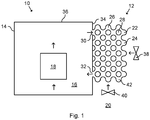
- Fig. 1 schematically represents a side view of a power transformer 10 comprising a heat exchanger 12.
- the power transformer 10 is one example of an electric arrangement.
- the power transformer 10 comprises a casing 14.
- the casing 14 contains dielectric oil 16.
- Dielectric oil 16 is one example of a dielectric cooling fluid.
- the power transformer 10 further comprises an electric component 18.
- the electric component 18 is arranged inside the casing 14.
- the electric component 18 is submerged in the oil 16.
- the electric component 18 generates heat during operation of the power transformer 10.
- the electric component 18 may for example be a winding of the power transformer 10.
- Fig. 1 further indicates ambient air 20 outside the casing 14.
- the air 20 may be the atmosphere.
- the air 20 is one example of an ambient fluid.
- the heat exchanger 12 comprises a three dimensional lattice cell structure 22.
- the three dimensional lattice cell structure 22 comprises a plurality of cells 24.
- the three dimensional lattice cell structure 22 of this example comprises a triply periodic substantially minimal surface having an elongated Schwarz P surface.
- the three dimensional lattice cell structure 22 may be for example be 3D printed.
- the three dimensional lattice cell structure 22 defines an interior lattice cell structure volume 26 and an exterior lattice cell structure volume 28.
- the interior lattice cell structure volume 26 and the exterior lattice cell structure volume 28 constitute two separate networks. Oil 16 from the interior of the casing 14 can flow into and out from the interior lattice cell structure volume 26.
- the air 20 can flow into and out from the exterior lattice cell structure volume 28.
- each of the interior lattice cell structure volume 26 and the exterior lattice cell structure volume 28 is continuous.
- the three dimensional lattice cell structure 22 is thus configured to conduct the oil 16 from the casing 14 to an exterior side of the casing 14 and back towards the casing 14.
- the three dimensional lattice cell structure 22 comprises large surface areas for heat exchange between the oil 16 and the air 20. Tests have shown that the heat exchanger 12 has a very high heat transfer coefficient. A number of radiators can thereby be reduced. Despite the large surface areas for heat exchange, the three dimensional lattice cell structure 22 is also compact.
- the heat exchanger 12 comprises an inlet 30 and an outlet 32.
- Each of the inlet 30 and the outlet 32 is arranged fluidly between the casing 14 and the three dimensional lattice cell structure 22.
- the inlet 30 is arranged geodetically higher than the outlet 32.
- the casing 14 and the three dimensional lattice cell structure 22 define a circuit for the oil 16 comprising the casing 14, the inlet 30, the three dimensional lattice cell structure 22 and the outlet 32.
- the oil 16 flows in this circuit in a clockwise direction during operation of the power transformer 10, as indicated with arrows. That is, the oil 16 is heated by the electric component 18.
- the hot oil 16 then enters the three dimensional lattice cell structure 22 through the inlet 30.
- the hot oil 16 in the interior lattice cell structure volume 26 is then cooled by heat exchange with the air 20 in the exterior lattice cell structure volume 28.
- Cold oil 16 then exits the three dimensional lattice cell structure 22 through the outlet 32.
- the electric component 18 is then cooled by the cold oil 16.
- the casing 14 comprises four side walls 34 and a top wall 36.
- the three dimensional lattice cell structure 22 is embedded in one of the side walls 34.
- the three dimensional lattice cell structure 22 may for example be welded or bolted to the side wall 34.
- the power transformer 10 further comprises a fan arrangement.
- the fan arrangement comprises a front fan 38 and a bottom fan 40.
- the front fan 38 is configured to blow the air 20 horizontally into the three dimensional lattice cell structure 22.
- the bottom fan 40 is configured to blow the air 20 vertically into the three dimensional lattice cell structure 22 from below.
- the cooling efficiency of the power transformer 10 can easily be regulated by adjusting the speeds of the fans 38, 40.
- the fan arrangement may also comprise a further fan (not shown) that blows the air 20 in a further horizontal direction, perpendicular to the blowing direction of the front fan 38.
- the three dimensional lattice cell structure 22 further comprises non-flat and flow-promoting ends 42. Each end 42 closes a respective cell 24 of the three dimensional lattice cell structure 22.
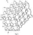
- Fig. 2 schematically represents a partial perspective view of the three dimensional lattice cell structure 22 of the heat exchanger 12 in Fig. 1 .
- the three dimensional lattice cell structure 22 comprises a periodic pattern in each of three orthogonal directions.
- Each periodic pattern comprises a plurality of periods.
- the cells 24 are arranged orthogonally in three directions.
- each non-flat and flow-promoting end 42 of this example has a shape of a cone.
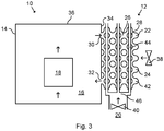
- Fig. 3 schematically represents a side view of a power transformer 10 comprising a further example of heat exchanger 12
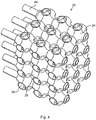
- Fig. 4 schematically represents a partial perspective view of the heat exchanger 12 in Fig. 3 .
- the heat exchanger 12 in Figs. 3 and 4 comprises a plurality of pipes 44.
- each pipe 44 is straight and vertically oriented.
- the pipes 44 are configured to guide the air 20 through the three dimensional lattice cell structure 22.
- Each pipe 44 extends through the entire three dimensional lattice cell structure 22.
- each pipe 44 extends through the cells 24 of the three dimensional lattice cell structure 22.
- the heat exchanger 12 in Fig. 3 further comprises a manifold 46.
- the manifold 46 branches into the pipes 44.
- the bottom fan 40 is arranged to blow air 20 through the pipes 44 via the manifold 46.
- the front fan 38 is arranged to blow air 20 into the three dimensional lattice cell structure 22 in the same manner as in Fig. 1 .
- heat exchange between the oil 16 and the air 20 takes place both between the interior lattice cell structure volume 26 and the exterior lattice cell structure volume 28 and between the interior lattice cell structure volume 26 and the pipes 44. In this way, heat transfer efficiency between the oil 16 and the air 20 is further increased.
- the heat exchanger 12 in Fig. 3 also has a simple structure.
- the pipes 44 in Figs. 3 and 4 may alternatively be configured as heat pipes containing two-phase coolant and provided with an interior capillary structure. In this case, the pipes 44 may extend further outside the three dimensional lattice cell structure 22.
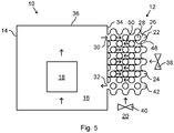
- Fig. 5 schematically represents a side view of a power transformer 10 comprising a further example of heat exchanger 12. Mainly differences with respect to Figs. 1 and 2 will be described.
- the heat exchanger 12 in Fig. 5 further comprises a plurality of plates 48.
- the plates 48 define a path 50 inside the interior lattice cell structure volume 26. As shown in Fig. 5 , the path 50 is serpentine-shaped.
- the plates 48 are one example of a guiding structure for guiding the oil 16 inside the three dimensional lattice cell structure 22.
- the plates 48 force the oil 16 to a distal (with respect to the casing 14) region of the three dimensional lattice cell structure 22.
- the plates 48 thereby further improve heat transfer between the oil 16 and the air 20 in the three dimensional lattice cell structure 22.
- Fig. 6 schematically represents a side view of a power transformer 10 comprising a further example of heat exchanger 12. Mainly differences with respect to Figs. 1 and 2 will be described.
- the heat exchanger 12 in Fig. 6 comprises a plurality of bodies 52.
- Each body 52 comprises a three dimensional lattice cell structure 22.
- the bodies 52 thus form a plurality of parallel networks for the oil 16.
- Each three dimensional lattice cell structure 22 is configured to conduct the oil 16 from the casing 14 at the exterior side of the casing 14 for heat exchange with the air 20, and back towards the casing 14 for cooling the electric component 18.
- Each body 52 is detachably connectable to the casing 14.
- the power transformer 10 can function even when one of the bodies 52 is removed for replacement. In this case, openings into the body 52 removed for replacement need to be closed. Replacement of only one body 52 is simpler and cheaper.
- the heat exchanger 12 comprises an upper manifold 54 and a lower manifold 56.
- the upper manifold 54 branches into the inlet 30 of each body 52.
- the outlet 32 of each body 52 are joined by the lower manifold 56.
- Each body 52 is detachably connectable to the upper manifold 54 and the lower manifold 56.
- the power transformer 10 in Fig. 6 further comprises a pump 58.
- the pump 58 constitutes one example of a pump arrangement.
- the pump 58 is configured to selectively enhance a flow of the oil 16 through the three dimensional lattice cell structure 22.
- the cooling efficiency of the power transformer 10 can easily be regulated by adjusting the speed of the pump 58.
- the pump 58 is arranged in the lower manifold 56, i.e. downstream of the bodies 52.
- the power transformer 10 in Fig. 6 further comprises a plurality of bottom fans 40.
- Each bottom fan 40 is arranged below one of the three dimensional lattice cell structure 22.
- One bottom fan 40 is associated with each three dimensional lattice cell structure 22.
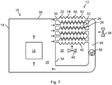
- Fig. 7 schematically represents a side view of a power transformer 10 comprising a further example of heat exchanger 12.
- the heat exchanger 12 comprises a plurality of panels 60.
- Fig. 8 schematically represents a perspective view of one of the panels 60 of the heat exchanger 12 in Fig. 7
- Fig. 9 schematically represents a front view of the panel 60 in Fig. 8 .
- the panels 60 are further examples of bodies according to the present disclosure. Each panel 60 is detachably connectable to the casing 14. Each panel 60 comprises a two dimensional lattice cell structure 62. Furthermore, each panel 60 in this example comprises a plurality of holes 64. The holes 64 are arranged between the cells 24.
- the panels 60 are arranged in a stack. In this way, the panels 60 jointly form a three dimensional lattice cell structure 22.
- the distance between the panels 60 may be varied, e.g. optimized for an improved heat transfer.
- each panel 60 is horizontally oriented.
- the interior lattice cell structure volume 26 is discontinuous.
- the three dimensional lattice cell structure 22 thus forms a plurality of parallel labyrinth networks for the oil 16, i.e. one network in each panel 60.
- the exterior lattice cell structure volume 28 is continuous.
- the panel 60 does not need to comprise the holes 64, for example if the panel 60 is made of sheet metal. In this case, the exterior lattice cell structure volume 28 would be discontinuous between the panels 60.
- the panels 60 are arranged in a dense configuration.
- the panels 60 are overlapping. That is, cells 24 of one panel 60 enter into respective spaces between cells 24 of an adjacent panel 60. Thus, the cells 24 of adjacent panels 60 are offset.
- non-flat ends 42 of the panels 60 may be replaced with flat ends.
- the panels 60 may be compactly arranged face-to-face with each other and the cells 24 of adjacent panels 60 do not need to be offset.
- the heat exchanger 12 further comprises a conduit 66.
- the outlet 32 of each panel 60 is connected to the conduit 66.
- the conduit 66 transitions (as seen in the flow direction of the oil 16) from vertical to horizontal prior to connecting to the casing 14.
- the pump 58 is arranged in the conduit 66, here in the vertical section thereof.
- the bottom fan 40 is arranged vertically between the three dimensional lattice cell structure 22 and the horizontal section of the conduit 66.
- the panel 60 according to Figs. 8 and 9 is merely one specific example. In particular, the design of the inlet 30 and the outlet 32 may be modified.
- Fig. 10 schematically represents a side view of a power transformer 10 comprising a further example of heat exchanger 12 and Fig. 11 schematically represents a front view of the power transformer 10 in Fig. 10 .
- Figs. 10 and 11 mainly differences with respect to Fig. 7 will be described.
- the panels 60 used in Figs. 10 and 11 are of the same type as in Figs. 8 and 9 . As shown in Figs. 10 and 11 , each panel 60 is vertically oriented. The panels 60 are arranged in a stack to jointly form a three dimensional lattice cell structure 22.
- Fig. 11 further shows that the fan arrangement comprises two further fans 68.
- Each fan 68 is arranged to blow the air 20 into the three dimensional lattice cell structure 22 in a horizontal direction, perpendicular to the blowing direction of the front fan 38.
Landscapes
- Engineering & Computer Science (AREA)
- Physics & Mathematics (AREA)
- Thermal Sciences (AREA)
- Mechanical Engineering (AREA)
- General Engineering & Computer Science (AREA)
- Power Engineering (AREA)
- Chemical & Material Sciences (AREA)
- Manufacturing & Machinery (AREA)
- Materials Engineering (AREA)
- Transformer Cooling (AREA)
- Heat-Exchange Devices With Radiators And Conduit Assemblies (AREA)
- Cooling Or The Like Of Electrical Apparatus (AREA)
Abstract
Description
- The present disclosure generally relates to heat exchangers for electric arrangements. In particular, an electric arrangement comprising a heat exchanger, a panel for a heat exchanger, and a heat exchanger comprising a plurality of panels, are provided.
- Transformer oil used in power transformers is often cooled by cooling arrangements, such as radiators or coolers. These cooling arrangements often constitute a significant part of the footprint of the transformer.
-
US 2020033070 A1 discloses a heat exchanger including an enclosure and a minimal surface structure within the enclosure. The enclosure includes a first inlet, a first outlet, a second inlet, and a second outlet. The minimal surface structure separates a first volume and a second volume within the enclosure. The first inlet and the first outlet are in fluid communication with the first volume, and the second inlet and a second outlet are in fluid communication with the second volume. The first and second volumes are separated from mixing with each other. - One object of the present disclosure is to provide an electric arrangement comprising a heat generating electric component and a heat exchanger, which electric arrangement enables an improved cooling of the electric component.
- A further object of the present disclosure is to provide an electric arrangement comprising a heat exchanger, which electric arrangement enables simple maintenance.
- A still further object of the present disclosure is to provide an electric arrangement comprising a heat exchanger, which electric arrangement has a compact design.
- A still further object of the present disclosure is to provide an electric arrangement comprising a heat exchanger, which electric arrangement has a low weight.
- A still further object of the present disclosure is to provide an electric arrangement comprising a heat exchanger, which electric arrangement requires low amounts of dielectric cooling fluid.
- A still further object of the present disclosure is to provide an electric arrangement comprising a heat exchanger, which electric arrangement solves several or all of the foregoing objects in combination.
- A still further object of the present disclosure is to provide a panel for a heat exchanger, which panel solves one, several or all of the foregoing objects.
- A still further object of the present disclosure is to provide a heat exchanger for an electric arrangement, which heat exchanger solves one, several or all of the foregoing objects.
- According to one aspect, there is provided an electric arrangement comprising a casing; a heat generating electric component arranged inside the casing; and a heat exchanger comprising a three dimensional lattice cell structure, the three dimensional lattice cell structure being arranged to conduct a dielectric cooling fluid from the casing at an exterior side of the casing for heat exchange with an ambient fluid, and back towards the casing for cooling of the electric component.
- The three dimensional lattice cell structure increases the surface areas exposed for heat transfer. Heat transfer efficiency is thus improved by means of the three dimensional lattice cell structure. Consequently, cooling efficiency of the electric component is also improved. Due to the high heat transfer efficiency of the heat exchanger, the amount of cooling fluid can also be relatively low. The three dimensional lattice cell structure further provides a good mixing environment and a low increase of pressure drop.
- The three dimensional lattice cell structure further enables a compact design of the heat exchanger. As a consequence, also the electric arrangement can be made more compact. Alternatively, the electric arrangement can be made more powerful with the same footprint.
- Furthermore, by means of the three dimensional lattice cell structure, the electric arrangement can be made lighter. This in turn reduces transportation costs. The three dimensional lattice cell structure also enables the electric arrangement to be manufactured more easily.
- The three dimensional lattice cell structure may comprise a periodic pattern in each of three different directions. Each periodic pattern may comprise at least three periods. The directions may be substantially orthogonal, or orthogonal. The three dimensional lattice cell structure comprises a plurality of cells. The cells may be arranged substantially orthogonally, or orthogonally, in two or three directions.
- The three dimensional lattice cell structure may define an interior lattice cell structure volume. The interior lattice cell structure volume may be continuous or discontinuous. Thus, the interior lattice cell structure volume may form a continuous labyrinth network for the cooling fluid, or may form several parallel labyrinth networks for the cooling fluid. In any case, the interior lattice cell structure volume may be in fluid communication with the interior of the casing.
- The three dimensional lattice cell structure may define an exterior lattice cell structure volume. The exterior lattice cell structure volume may be continuous or discontinuous. Thus, the exterior lattice cell structure volume may form a continuous labyrinth network for the ambient fluid, or may form several parallel labyrinth networks for the ambient fluid. In any case, the exterior lattice cell structure volume may be in fluid communication with the ambient fluid.
- The cooling fluid may be a dielectric liquid, such as dielectric oil. The ambient fluid may be ambient air or water.
- The casing and the three dimensional lattice cell structure may define a circuit for the cooling fluid. The heat exchanger may comprise one or more inlets and one or more outlets. In this case, the three dimensional lattice cell structure may be arranged fluidly between the one or more inlets and the one or more outlets. Each inlet and each outlet may be arranged fluidly between the casing and the three dimensional lattice cell structure. The inlet may be arranged geodetically higher than the outlet.
- The casing may comprise a plurality of walls. The three dimensional lattice cell structure may be embedded in one of the walls. Alternatively, or in addition, the three dimensional lattice cell structure maybe welded or bolted to one of the walls.
- The heat exchanger may comprise a plurality of bodies, each body comprising a three dimensional lattice cell structure or a two dimensional lattice structure. Each body may be integrally formed. For example, each body may be additively manufactured. One example of additive manufacture is 3D printing.
- Each body may be detachably connected to the casing. This lowers assembly time and facilitates repair. For example, one of the bodies may be replaced without replacing the remaining bodies. One reason for needing replacement may be leakage.
- Each body may be a panel comprising a two dimensional lattice cell structure. The two dimensional lattice cell structure may comprise a periodic pattern in each of two different directions. Each periodic pattern may comprise at least three periods. The directions maybe substantially orthogonal, or orthogonal.
- The panels may be arranged in a stack to form the three dimensional lattice cell structure. In this case, cells of adjacent panels maybe aligned or offset. Alternatively, each body may be elongated, such as pipe-shaped.
- The three dimensional lattice cell structure may comprise a triply periodic substantially minimal surface, such as a triply periodic minimal surface, TPMS. The TPMS may for example comprise a Schwarz P surface. The triply periodic substantially minimal surface may be a surface that is similar to a TPMS, but that does not fulfill the requirement to be named TPMS.
- The three dimensional lattice cell structure may comprise non-flat and flow-promoting ends. The ends may for example be cones or hemispheres. Each end may close a respective cell of the three dimensional lattice cell structure.
- The heat exchanger may comprise two three dimensional lattice cell structures arranged in parallel, and each three dimensional lattice cell structure may be arranged to conduct the cooling fluid from the casing at the exterior side of the casing for heat exchange with an ambient fluid, and back towards the casing for cooling of the electric component. In this case, the heat exchanger may comprise a plurality of inlets and a plurality of outlets. Each pair of an inlet and an outlet may be associated with one three dimensional lattice cell structure. Each three dimensional lattice cell structure may be arranged fluidly between the associated inlet and outlet.
- The heat exchanger may further comprise pipes for conducting the ambient fluid through the three dimensional lattice cell structure. In this case, the ambient fluid may flow through the three dimensional lattice cell structure both inside and outside the pipes. That is, the ambient fluid may flow both inside the pipes and inside the exterior lattice cell structure volume. This further increases the heat transfer between the cooling fluid and the ambient fluid. The pipes may extend through cells of the three dimensional lattice cell structure.
- As an alternative, the pipes may be heat pipes containing two-phase coolant. In this case, an interior surface of the heat pipes may comprise a capillary structure. Sections of the heat pipes outside the three dimensional lattice cell structure may constitute a condenser region and sections of the heat pipes inside the three dimensional lattice cell structure may constitute an evaporator region. In the evaporator region of the heat pipes adjacent to the cooling fluid, the two-phase coolant absorbs heat from the cooling fluid and evaporates. The vapour travels inside the heat pipes, but outside the capillary structure, to the lower temperature condenser region of the heat pipes outside the three dimensional lattice cell structure, where the vapour condenses back to liquid and is absorbed by the capillary structure. The liquid then travels inside the capillary structure from the condenser region back to the evaporator region.
- The heat exchanger may comprise a guiding structure inside the three dimensional lattice cell structure, the guiding structure being arranged to guide the cooling fluid along a defined path inside the three dimensional lattice cell structure. The path may pass through substantially the entire, or the entire, three dimensional lattice cell structure. The path may be a serpentine path. The guiding structure may comprise a plurality of plates.
- The electric arrangement may further comprise a pump arrangement arranged to generate a flow of the cooling fluid through the three dimensional lattice cell structure. This further improves the heat exchange. The pump arrangement may comprise one or more pumps. Alternatively, the electric arrangement may be configured to circulate the cooling fluid only by means of natural convection, i.e. without any mechanical assistance for circulating the cooling fluid.
- The electric arrangement may further comprise a fan arrangement arranged to generate a flow of the ambient fluid in the three dimensional lattice cell structure. This further improves the heat exchange. The fan arrangement may be arranged to generate a flow of the ambient fluid through the three dimensional lattice cell structure. The fan arrangement may comprise one or more fans.
- The fan arrangement may be arranged to generate a flow of the ambient fluid in the three dimensional lattice cell structure in at least two different directions, such as in at least three different directions. The directions may be substantially orthogonal, or orthogonal.
- The electric arrangement may be a high voltage static electric induction system, such as a power transformer or a shunt reactor. As used herein, a high voltage may be at least 30 kV, such as at least 100 kV. Although the electric arrangement is mainly described as a power transformer, the electric arrangement is not limited to a power transformer.
- According to a further aspect, there is provided a panel for a heat exchanger, the panel comprising an inlet, an outlet and a two dimensional lattice cell structure fluidly between the inlet and the outlet. The panel may be of any type according to the present disclosure.
- According to a further aspect, there is provided a heat exchanger for an electric arrangement, the heat exchanger comprising a plurality of panels according to the present disclosure, the panels being arranged in a stack to form a three dimensional lattice cell structure. Cells of adjacent panels may be aligned or offset.
- Each panel may comprise a two dimensional lattice cell structure. The two dimensional lattice cell structure may comprise a periodic pattern in each of two different directions. Each periodic pattern may comprise at least three periods. The directions may be substantially orthogonal, or orthogonal.
- Further details, advantages and aspects of the present disclosure will become apparent from the following embodiments taken in conjunction with the drawings, wherein:
- Fig. 1:
- schematically represents a side view of an electric arrangement comprising a heat exchanger;
- Fig. 2:
- schematically represents a partial perspective view of a three dimensional lattice cell structure of the heat exchanger in
Fig. 1 ; - Fig. 3:
- schematically represents a side view of an electric arrangement comprising a further example of heat exchanger;
- Fig. 4:
- schematically represents a partial perspective view of the heat exchanger in
Fig. 3 ; - Fig. 5:
- schematically represents a side view of an electric arrangement comprising a further example of heat exchanger;
- Fig. 6:
- schematically represents a side view of an electric arrangement comprising a further example of heat exchanger;
- Fig. 7:
- schematically represents a side view of an electric arrangement comprising a further example of heat exchanger;
- Fig. 8:
- schematically represents a perspective view of a panel of the heat exchanger in
Fig. 7 ; - Fig. 9:
- schematically represents a front view of the panel in
Fig. 8 ; - Fig. 10:
- schematically represents a side view of an electric arrangement comprising a further example of heat exchanger; and
- Fig. 11:
- schematically represents a front view of the electric arrangement in
Fig. 10 . - In the following, an electric arrangement comprising a heat exchanger, a panel for a heat exchanger, and a heat exchanger comprising a plurality of panels, will be described. The same or similar reference numerals will be used to denote the same or similar structural features.
-
Fig. 1 schematically represents a side view of apower transformer 10 comprising aheat exchanger 12. Thepower transformer 10 is one example of an electric arrangement. Thepower transformer 10 comprises acasing 14. Thecasing 14 containsdielectric oil 16.Dielectric oil 16 is one example of a dielectric cooling fluid. - The
power transformer 10 further comprises anelectric component 18. Theelectric component 18 is arranged inside thecasing 14. Theelectric component 18 is submerged in theoil 16. Theelectric component 18 generates heat during operation of thepower transformer 10. Theelectric component 18 may for example be a winding of thepower transformer 10. -
Fig. 1 further indicatesambient air 20 outside thecasing 14. Theair 20 may be the atmosphere. Theair 20 is one example of an ambient fluid. - The
heat exchanger 12 comprises a three dimensionallattice cell structure 22. The three dimensionallattice cell structure 22 comprises a plurality ofcells 24. The three dimensionallattice cell structure 22 of this example comprises a triply periodic substantially minimal surface having an elongated Schwarz P surface. The three dimensionallattice cell structure 22 may be for example be 3D printed. - The three dimensional
lattice cell structure 22 defines an interior latticecell structure volume 26 and an exterior latticecell structure volume 28. The interior latticecell structure volume 26 and the exterior latticecell structure volume 28 constitute two separate networks.Oil 16 from the interior of thecasing 14 can flow into and out from the interior latticecell structure volume 26. Theair 20 can flow into and out from the exterior latticecell structure volume 28. In this example, each of the interior latticecell structure volume 26 and the exterior latticecell structure volume 28 is continuous. - The three dimensional
lattice cell structure 22 is thus configured to conduct theoil 16 from thecasing 14 to an exterior side of thecasing 14 and back towards thecasing 14. The three dimensionallattice cell structure 22 comprises large surface areas for heat exchange between theoil 16 and theair 20. Tests have shown that theheat exchanger 12 has a very high heat transfer coefficient. A number of radiators can thereby be reduced. Despite the large surface areas for heat exchange, the three dimensionallattice cell structure 22 is also compact. - The
heat exchanger 12 comprises aninlet 30 and anoutlet 32. Each of theinlet 30 and theoutlet 32 is arranged fluidly between thecasing 14 and the three dimensionallattice cell structure 22. Theinlet 30 is arranged geodetically higher than theoutlet 32. - As shown in
Fig. 1 , thecasing 14 and the three dimensionallattice cell structure 22 define a circuit for theoil 16 comprising thecasing 14, theinlet 30, the three dimensionallattice cell structure 22 and theoutlet 32. InFig. 1 , theoil 16 flows in this circuit in a clockwise direction during operation of thepower transformer 10, as indicated with arrows. That is, theoil 16 is heated by theelectric component 18. Thehot oil 16 then enters the three dimensionallattice cell structure 22 through theinlet 30. Thehot oil 16 in the interior latticecell structure volume 26 is then cooled by heat exchange with theair 20 in the exterior latticecell structure volume 28.Cold oil 16 then exits the three dimensionallattice cell structure 22 through theoutlet 32. Theelectric component 18 is then cooled by thecold oil 16. - The
casing 14 comprises fourside walls 34 and atop wall 36. In the example inFig 1 , the three dimensionallattice cell structure 22 is embedded in one of theside walls 34. The three dimensionallattice cell structure 22 may for example be welded or bolted to theside wall 34. - The
power transformer 10 further comprises a fan arrangement. The fan arrangement comprises afront fan 38 and abottom fan 40. Thefront fan 38 is configured to blow theair 20 horizontally into the three dimensionallattice cell structure 22. Thebottom fan 40 is configured to blow theair 20 vertically into the three dimensionallattice cell structure 22 from below. The cooling efficiency of thepower transformer 10 can easily be regulated by adjusting the speeds of thefans air 20 in a further horizontal direction, perpendicular to the blowing direction of thefront fan 38. - The three dimensional
lattice cell structure 22 further comprises non-flat and flow-promoting ends 42. Eachend 42 closes arespective cell 24 of the three dimensionallattice cell structure 22. -
Fig. 2 schematically represents a partial perspective view of the three dimensionallattice cell structure 22 of theheat exchanger 12 inFig. 1 . As shown inFig. 2 , the three dimensionallattice cell structure 22 comprises a periodic pattern in each of three orthogonal directions. Each periodic pattern comprises a plurality of periods. Thecells 24 are arranged orthogonally in three directions. As shown inFig. 2 , each non-flat and flow-promotingend 42 of this example has a shape of a cone. -
Fig. 3 schematically represents a side view of apower transformer 10 comprising a further example ofheat exchanger 12 andFig. 4 schematically represents a partial perspective view of theheat exchanger 12 inFig. 3 . With collective reference toFigs. 3 and4 , mainly differences with respect toFigs. 1 and2 will be described. - The
heat exchanger 12 inFigs. 3 and4 comprises a plurality ofpipes 44. In this example, eachpipe 44 is straight and vertically oriented. Thepipes 44 are configured to guide theair 20 through the three dimensionallattice cell structure 22. - Each
pipe 44 extends through the entire three dimensionallattice cell structure 22. In this example, eachpipe 44 extends through thecells 24 of the three dimensionallattice cell structure 22. - The
heat exchanger 12 inFig. 3 further comprises a manifold 46. The manifold 46 branches into thepipes 44. Thebottom fan 40 is arranged to blowair 20 through thepipes 44 via themanifold 46. Thefront fan 38 is arranged to blowair 20 into the three dimensionallattice cell structure 22 in the same manner as inFig. 1 . Thus, inFig. 3 , heat exchange between theoil 16 and theair 20 takes place both between the interior latticecell structure volume 26 and the exterior latticecell structure volume 28 and between the interior latticecell structure volume 26 and thepipes 44. In this way, heat transfer efficiency between theoil 16 and theair 20 is further increased. Theheat exchanger 12 inFig. 3 also has a simple structure. - The
pipes 44 inFigs. 3 and4 may alternatively be configured as heat pipes containing two-phase coolant and provided with an interior capillary structure. In this case, thepipes 44 may extend further outside the three dimensionallattice cell structure 22. -
Fig. 5 schematically represents a side view of apower transformer 10 comprising a further example ofheat exchanger 12. Mainly differences with respect toFigs. 1 and2 will be described. - The
heat exchanger 12 inFig. 5 further comprises a plurality ofplates 48. Theplates 48 define apath 50 inside the interior latticecell structure volume 26. As shown inFig. 5 , thepath 50 is serpentine-shaped. Theplates 48 are one example of a guiding structure for guiding theoil 16 inside the three dimensionallattice cell structure 22. - As shown in
Fig. 5 , theplates 48 force theoil 16 to a distal (with respect to the casing 14) region of the three dimensionallattice cell structure 22. Theplates 48 thereby further improve heat transfer between theoil 16 and theair 20 in the three dimensionallattice cell structure 22. -
Fig. 6 schematically represents a side view of apower transformer 10 comprising a further example ofheat exchanger 12. Mainly differences with respect toFigs. 1 and2 will be described. - The
heat exchanger 12 inFig. 6 comprises a plurality ofbodies 52. Eachbody 52 comprises a three dimensionallattice cell structure 22. Thebodies 52 thus form a plurality of parallel networks for theoil 16. Each three dimensionallattice cell structure 22 is configured to conduct theoil 16 from thecasing 14 at the exterior side of thecasing 14 for heat exchange with theair 20, and back towards thecasing 14 for cooling theelectric component 18. - Each
body 52 is detachably connectable to thecasing 14. Thepower transformer 10 can function even when one of thebodies 52 is removed for replacement. In this case, openings into thebody 52 removed for replacement need to be closed. Replacement of only onebody 52 is simpler and cheaper. - The
bodies 52 do however not need to be directly connectable to thecasing 14. As shown inFig. 6 , theheat exchanger 12 comprises anupper manifold 54 and alower manifold 56. Theupper manifold 54 branches into theinlet 30 of eachbody 52. Theoutlet 32 of eachbody 52 are joined by thelower manifold 56. Eachbody 52 is detachably connectable to theupper manifold 54 and thelower manifold 56. - The
power transformer 10 inFig. 6 further comprises apump 58. Thepump 58 constitutes one example of a pump arrangement. Thepump 58 is configured to selectively enhance a flow of theoil 16 through the three dimensionallattice cell structure 22. The cooling efficiency of thepower transformer 10 can easily be regulated by adjusting the speed of thepump 58. In the example inFig. 6 , thepump 58 is arranged in thelower manifold 56, i.e. downstream of thebodies 52. - The
power transformer 10 inFig. 6 further comprises a plurality ofbottom fans 40. Eachbottom fan 40 is arranged below one of the three dimensionallattice cell structure 22. Onebottom fan 40 is associated with each three dimensionallattice cell structure 22. -
Fig. 7 schematically represents a side view of apower transformer 10 comprising a further example ofheat exchanger 12. Theheat exchanger 12 comprises a plurality ofpanels 60.Fig. 8 schematically represents a perspective view of one of thepanels 60 of theheat exchanger 12 inFig. 7 , andFig. 9 schematically represents a front view of thepanel 60 inFig. 8 . With collective reference toFigs. 7-9 , mainly differences with respect toFig. 6 will be described. - The
panels 60 are further examples of bodies according to the present disclosure. Eachpanel 60 is detachably connectable to thecasing 14. Eachpanel 60 comprises a two dimensionallattice cell structure 62. Furthermore, eachpanel 60 in this example comprises a plurality ofholes 64. Theholes 64 are arranged between thecells 24. - The
panels 60 are arranged in a stack. In this way, thepanels 60 jointly form a three dimensionallattice cell structure 22. The distance between thepanels 60 may be varied, e.g. optimized for an improved heat transfer. As shown inFig. 7 , eachpanel 60 is horizontally oriented. In the example inFigs. 7-9 , the interior latticecell structure volume 26 is discontinuous. The three dimensionallattice cell structure 22 thus forms a plurality of parallel labyrinth networks for theoil 16, i.e. one network in eachpanel 60. - By means of the
holes 64, the exterior latticecell structure volume 28 is continuous. However, thepanel 60 does not need to comprise theholes 64, for example if thepanel 60 is made of sheet metal. In this case, the exterior latticecell structure volume 28 would be discontinuous between thepanels 60. - The
panels 60 are arranged in a dense configuration. In this example, thepanels 60 are overlapping. That is,cells 24 of onepanel 60 enter into respective spaces betweencells 24 of anadjacent panel 60. Thus, thecells 24 ofadjacent panels 60 are offset. - As an alternative, the non-flat ends 42 of the
panels 60 may be replaced with flat ends. In this case, thepanels 60 may be compactly arranged face-to-face with each other and thecells 24 ofadjacent panels 60 do not need to be offset. - The
heat exchanger 12 further comprises aconduit 66. Theoutlet 32 of eachpanel 60 is connected to theconduit 66. Theconduit 66 transitions (as seen in the flow direction of the oil 16) from vertical to horizontal prior to connecting to thecasing 14. Thepump 58 is arranged in theconduit 66, here in the vertical section thereof. Thebottom fan 40 is arranged vertically between the three dimensionallattice cell structure 22 and the horizontal section of theconduit 66. - The
panel 60 according toFigs. 8 and 9 is merely one specific example. In particular, the design of theinlet 30 and theoutlet 32 may be modified. -
Fig. 10 schematically represents a side view of apower transformer 10 comprising a further example ofheat exchanger 12 andFig. 11 schematically represents a front view of thepower transformer 10 inFig. 10 . With collective reference toFigs. 10 and 11 , mainly differences with respect toFig. 7 will be described. - The
panels 60 used inFigs. 10 and 11 are of the same type as inFigs. 8 and 9 . As shown inFigs. 10 and 11 , eachpanel 60 is vertically oriented. Thepanels 60 are arranged in a stack to jointly form a three dimensionallattice cell structure 22. -
Fig. 11 further shows that the fan arrangement comprises twofurther fans 68. Eachfan 68 is arranged to blow theair 20 into the three dimensionallattice cell structure 22 in a horizontal direction, perpendicular to the blowing direction of thefront fan 38. - While the present disclosure has been described with reference to exemplary embodiments, it will be appreciated that the present invention is not limited to what has been described above. For example, it will be appreciated that the dimensions of the parts may be varied as needed. Accordingly, it is intended that the present invention may be limited only by the scope of the claims appended hereto.
Claims (15)
- An electric arrangement (10) comprising:- a casing (14);- a heat generating electric component (18) arranged inside the casing (14); and- a heat exchanger (12) comprising a three dimensional lattice cell structure (22), the three dimensional lattice cell structure (22) being arranged to conduct a dielectric cooling fluid (16) from the casing (14) at an exterior side of the casing (14) for heat exchange with an ambient fluid (20), and back towards the casing (14) for cooling of the electric component (18).
- The electric arrangement (10) according to claim 1, wherein the heat exchanger (12) comprises a plurality of bodies (52, 60), each body (52, 60) comprising a three dimensional lattice cell structure (22) or a two dimensional lattice structure (62).
- The electric arrangement (10) according to claim 2, wherein each body (52, 60) is detachably connected to the casing (14).
- The electric arrangement (10) according to claim 2 or 3, wherein each body is a panel (60) comprising a two dimensional lattice cell structure (62).
- The electric arrangement (10) according to claim 4, wherein the panels (60) are arranged in a stack to form the three dimensional lattice cell structure (22).
- The electric arrangement (10) according to any of the preceding claims, wherein the three dimensional lattice cell structure (22) comprises a triply periodic substantially minimal surface.
- The electric arrangement (10) according to any of the preceding claims, wherein the three dimensional lattice cell structure (22) comprises non-flat and flow-promoting ends (42).
- The electric arrangement (10) according to any of the preceding claims, wherein the heat exchanger (12) comprises two three dimensional lattice cell structures (22) arranged in parallel, and wherein each three dimensional lattice cell structure (22) is arranged to conduct the cooling fluid (16) from the casing (14) at the exterior side of the casing (14) for heat exchange with an ambient fluid (20), and back towards the casing (14) for cooling of the electric component (18).
- The electric arrangement (10) according to any of the preceding claims, wherein the heat exchanger (12) further comprises pipes (44) for conducting the ambient fluid (20) through the three dimensional lattice cell structure (22).
- The electric arrangement (10) according to any of the preceding claims, wherein the heat exchanger (12) comprises a guiding structure (48) inside the three dimensional lattice cell structure (22), the guiding structure (48) being arranged to guide the cooling fluid (16) along a defined path (50) inside the three dimensional lattice cell structure (22).
- The electric arrangement (10) according to any of the preceding claims, further comprising a pump arrangement (58) arranged to generate a flow of the cooling fluid (16) through the three dimensional lattice cell structure (22).
- The electric arrangement (10) according to any of the preceding claims, further comprising a fan arrangement (38, 40, 68) arranged to generate a flow of the ambient fluid (20) in the three dimensional lattice cell structure (22).
- The electric arrangement (10) according to claim 12, wherein the fan arrangement (38, 40, 68) is arranged to generate a flow of the ambient fluid (20) in the three dimensional lattice cell structure (22) in at least two different directions.
- A panel (60) for a heat exchanger (12), the panel (60) comprising an inlet (30), an outlet (32) and a two dimensional lattice cell structure (62) fluidly between the inlet (30) and the outlet (32).
- A heat exchanger (12) for an electric arrangement (10), the heat exchanger (12) comprising a plurality of panels (60) according to claim 14, the panels (60) being arranged in a stack to form a three dimensional lattice cell structure (22).
Priority Applications (6)
| Application Number | Priority Date | Filing Date | Title |
|---|---|---|---|
| EP20172413.5A EP3904818B1 (en) | 2020-04-30 | 2020-04-30 | Electric arrangement comprising a heat exchanger |
| PCT/EP2021/057936 WO2021219305A1 (en) | 2020-04-30 | 2021-03-26 | Electric arrangement, panel and heat exchanger |
| CN202180031335.8A CN115485522A (en) | 2020-04-30 | 2021-03-26 | Electrical installations, panels and heat exchangers |
| JP2022566291A JP7499354B2 (en) | 2020-04-30 | 2021-03-26 | Electrical equipment, panels and heat exchangers |
| US17/918,984 US20230314094A1 (en) | 2020-04-30 | 2021-03-26 | Electric arrangement, panel and heat exchanger |
| KR1020227037746A KR102779398B1 (en) | 2020-04-30 | 2021-03-26 | Electrical arrays, panels and heat exchangers |
Applications Claiming Priority (1)
| Application Number | Priority Date | Filing Date | Title |
|---|---|---|---|
| EP20172413.5A EP3904818B1 (en) | 2020-04-30 | 2020-04-30 | Electric arrangement comprising a heat exchanger |
Publications (3)
| Publication Number | Publication Date |
|---|---|
| EP3904818A1 true EP3904818A1 (en) | 2021-11-03 |
| EP3904818B1 EP3904818B1 (en) | 2024-01-10 |
| EP3904818C0 EP3904818C0 (en) | 2024-01-10 |
Family
ID=70482388
Family Applications (1)
| Application Number | Title | Priority Date | Filing Date |
|---|---|---|---|
| EP20172413.5A Active EP3904818B1 (en) | 2020-04-30 | 2020-04-30 | Electric arrangement comprising a heat exchanger |
Country Status (6)
| Country | Link |
|---|---|
| US (1) | US20230314094A1 (en) |
| EP (1) | EP3904818B1 (en) |
| JP (1) | JP7499354B2 (en) |
| KR (1) | KR102779398B1 (en) |
| CN (1) | CN115485522A (en) |
| WO (1) | WO2021219305A1 (en) |
Cited By (3)
| Publication number | Priority date | Publication date | Assignee | Title |
|---|---|---|---|---|
| WO2024063222A1 (en) * | 2022-09-19 | 2024-03-28 | 서울과학기술대학교 산학협력단 | Microcellular heat exchanger using local filtering |
| WO2024170102A1 (en) * | 2023-02-15 | 2024-08-22 | Hitachi Energy Ltd | Heat generating electric component tank |
| EP4525009A1 (en) * | 2023-09-15 | 2025-03-19 | Hitachi Energy Ltd | High voltage device |
Families Citing this family (3)
| Publication number | Priority date | Publication date | Assignee | Title |
|---|---|---|---|---|
| US20240230249A9 (en) * | 2022-10-21 | 2024-07-11 | General Electric Company | Heat exchanger assembly formed of a lattice structure with a plurality of shell structure unit cells |
| DE102022131601A1 (en) * | 2022-11-29 | 2024-05-29 | Friedrich Boysen GmbH & Co KG. | Heating device for heating a gas stream |
| CN118463660B (en) * | 2024-07-12 | 2024-11-01 | 广东巴斯特科技股份有限公司 | Multi-dimensional heat exchange structure and static hybrid heat exchanger thereof |
Citations (4)
| Publication number | Priority date | Publication date | Assignee | Title |
|---|---|---|---|---|
| EP2466086A1 (en) * | 2010-12-15 | 2012-06-20 | Benteler Automobiltechnik GmbH | Heat exchanger |
| US20180187984A1 (en) * | 2017-01-03 | 2018-07-05 | Titan Tensor LLC | Monolithic Bicontinuous Labyrinth Structures and Methods For Their Manufacture |
| EP3431911A1 (en) * | 2017-07-19 | 2019-01-23 | General Electric Company | Additively manufactured heat exchanger |
| US20200033070A1 (en) * | 2018-07-25 | 2020-01-30 | Andreas Vlahinos | Minimal surface heat exchanger |
Family Cites Families (9)
| Publication number | Priority date | Publication date | Assignee | Title |
|---|---|---|---|---|
| US4302793A (en) * | 1979-11-30 | 1981-11-24 | Submergible Oil Systems, Inc. | Electronic cooling |
| JPH088421B2 (en) * | 1991-03-20 | 1996-01-29 | さとみ 伊藤 | Heat dissipation device |
| US6623687B1 (en) * | 1999-08-06 | 2003-09-23 | Milwaukee School Of Engineering | Process of making a three-dimensional object |
| BR0108629A (en) | 2000-02-24 | 2003-12-23 | Unifin International Inc | System and method for transformer cooling |
| DE102008003672A1 (en) * | 2008-01-09 | 2009-07-16 | Areva Energietechnik Gmbh | Electric transformer unit |
| US20130058042A1 (en) | 2011-09-03 | 2013-03-07 | Todd Richard Salamon | Laminated heat sinks |
| WO2015160324A1 (en) * | 2014-04-14 | 2015-10-22 | United Technologies Corporation | Container having an internal structure with minimum surfaces |
| CN204555743U (en) * | 2014-12-17 | 2015-08-12 | 广西职业技术学院 | A kind of bionical heat exchanger |
| US10130009B2 (en) | 2017-03-15 | 2018-11-13 | American Superconductor Corporation | Natural convection cooling for power electronics systems having discrete power dissipation components |
-
2020
- 2020-04-30 EP EP20172413.5A patent/EP3904818B1/en active Active
-
2021
- 2021-03-26 US US17/918,984 patent/US20230314094A1/en active Pending
- 2021-03-26 JP JP2022566291A patent/JP7499354B2/en active Active
- 2021-03-26 CN CN202180031335.8A patent/CN115485522A/en active Pending
- 2021-03-26 WO PCT/EP2021/057936 patent/WO2021219305A1/en active Application Filing
- 2021-03-26 KR KR1020227037746A patent/KR102779398B1/en active Active
Patent Citations (4)
| Publication number | Priority date | Publication date | Assignee | Title |
|---|---|---|---|---|
| EP2466086A1 (en) * | 2010-12-15 | 2012-06-20 | Benteler Automobiltechnik GmbH | Heat exchanger |
| US20180187984A1 (en) * | 2017-01-03 | 2018-07-05 | Titan Tensor LLC | Monolithic Bicontinuous Labyrinth Structures and Methods For Their Manufacture |
| EP3431911A1 (en) * | 2017-07-19 | 2019-01-23 | General Electric Company | Additively manufactured heat exchanger |
| US20200033070A1 (en) * | 2018-07-25 | 2020-01-30 | Andreas Vlahinos | Minimal surface heat exchanger |
Cited By (4)
| Publication number | Priority date | Publication date | Assignee | Title |
|---|---|---|---|---|
| WO2024063222A1 (en) * | 2022-09-19 | 2024-03-28 | 서울과학기술대학교 산학협력단 | Microcellular heat exchanger using local filtering |
| WO2024170102A1 (en) * | 2023-02-15 | 2024-08-22 | Hitachi Energy Ltd | Heat generating electric component tank |
| EP4525009A1 (en) * | 2023-09-15 | 2025-03-19 | Hitachi Energy Ltd | High voltage device |
| WO2025056196A1 (en) * | 2023-09-15 | 2025-03-20 | Hitachi Energy Ltd | High-voltage device |
Also Published As
| Publication number | Publication date |
|---|---|
| EP3904818B1 (en) | 2024-01-10 |
| US20230314094A1 (en) | 2023-10-05 |
| WO2021219305A1 (en) | 2021-11-04 |
| CN115485522A (en) | 2022-12-16 |
| KR102779398B1 (en) | 2025-03-10 |
| KR20220159460A (en) | 2022-12-02 |
| EP3904818C0 (en) | 2024-01-10 |
| JP2023524485A (en) | 2023-06-12 |
| JP7499354B2 (en) | 2024-06-13 |
Similar Documents
| Publication | Publication Date | Title |
|---|---|---|
| EP3904818B1 (en) | Electric arrangement comprising a heat exchanger | |
| CN103096693B (en) | With the rack of module with thermal siphon chiller assembly | |
| KR101532817B1 (en) | Thermosiphon cooler arrangement in modules with electric and/or electronic components | |
| EP2625484B1 (en) | Cooling of an electric machine | |
| US20130019627A1 (en) | Cooling apparatus and cooling system for electronic-device exhaustion | |
| EP2565571A1 (en) | Vehicle interior heat exchanger | |
| EP4121989B1 (en) | Heat exchanger and electric arrangement comprising heat exchanger | |
| EP2284846A1 (en) | Dry transformer cooled by means of a compact thermosyphon air to air heat exchanger | |
| EP3009781B1 (en) | Heat exchanger | |
| CN109891732B (en) | Thermoelectric power generation system | |
| KR102624703B1 (en) | Cooling module for fuel cell vehicle | |
| CN120186943A (en) | A heat exchange structure and inverter | |
| WO2017203973A1 (en) | Thermoelectric power generation device | |
| CN220041071U (en) | Single-phase immersed cooling system | |
| EP3465047B1 (en) | A heat exchanger for an electrical machine | |
| CN113716011B (en) | Auxiliary cooling system for pump for ship | |
| KR102687578B1 (en) | Multiple heat exchanger | |
| CN110986639B (en) | A thermosyphon heat exchanger | |
| CN115551294B (en) | An air cooling device for radar environmental control | |
| KR20200033618A (en) | Cooling apparatus for vehicle having fuel cell | |
| US20250008700A1 (en) | Cooling system for electronic component racks | |
| WO2024170102A1 (en) | Heat generating electric component tank |
Legal Events
| Date | Code | Title | Description |
|---|---|---|---|
| PUAI | Public reference made under article 153(3) epc to a published international application that has entered the european phase |
Free format text: ORIGINAL CODE: 0009012 |
|
| STAA | Information on the status of an ep patent application or granted ep patent |
Free format text: STATUS: THE APPLICATION HAS BEEN PUBLISHED |
|
| AK | Designated contracting states |
Kind code of ref document: A1 Designated state(s): AL AT BE BG CH CY CZ DE DK EE ES FI FR GB GR HR HU IE IS IT LI LT LU LV MC MK MT NL NO PL PT RO RS SE SI SK SM TR |
|
| B565 | Issuance of search results under rule 164(2) epc |
Effective date: 20201103 |
|
| RAP3 | Party data changed (applicant data changed or rights of an application transferred) |
Owner name: HITACHI ENERGY SWITZERLAND AG |
|
| STAA | Information on the status of an ep patent application or granted ep patent |
Free format text: STATUS: REQUEST FOR EXAMINATION WAS MADE |
|
| 17P | Request for examination filed |
Effective date: 20220502 |
|
| RBV | Designated contracting states (corrected) |
Designated state(s): AL AT BE BG CH CY CZ DE DK EE ES FI FR GB GR HR HU IE IS IT LI LT LU LV MC MK MT NL NO PL PT RO RS SE SI SK SM TR |
|
| P01 | Opt-out of the competence of the unified patent court (upc) registered |
Effective date: 20230527 |
|
| GRAP | Despatch of communication of intention to grant a patent |
Free format text: ORIGINAL CODE: EPIDOSNIGR1 |
|
| STAA | Information on the status of an ep patent application or granted ep patent |
Free format text: STATUS: GRANT OF PATENT IS INTENDED |
|
| INTG | Intention to grant announced |
Effective date: 20230925 |
|
| RAP1 | Party data changed (applicant data changed or rights of an application transferred) |
Owner name: HITACHI ENERGY LTD |
|
| GRAS | Grant fee paid |
Free format text: ORIGINAL CODE: EPIDOSNIGR3 |
|
| GRAA | (expected) grant |
Free format text: ORIGINAL CODE: 0009210 |
|
| STAA | Information on the status of an ep patent application or granted ep patent |
Free format text: STATUS: THE PATENT HAS BEEN GRANTED |
|
| AK | Designated contracting states |
Kind code of ref document: B1 Designated state(s): AL AT BE BG CH CY CZ DE DK EE ES FI FR GB GR HR HU IE IS IT LI LT LU LV MC MK MT NL NO PL PT RO RS SE SI SK SM TR |
|
| REG | Reference to a national code |
Ref country code: GB Ref legal event code: FG4D |
|
| RIN1 | Information on inventor provided before grant (corrected) |
Inventor name: MALEKSAEEDI, SAEED Inventor name: SAND, ULF Inventor name: THOLENCE, FREDERIC Inventor name: BEL FDHILA, REBEI Inventor name: AGUIRRE, MIGUEL Inventor name: BRODEUR, SAMUEL |
|
| REG | Reference to a national code |
Ref country code: CH Ref legal event code: EP |
|
| REG | Reference to a national code |
Ref country code: DE Ref legal event code: R096 Ref document number: 602020024093 Country of ref document: DE |
|
| REG | Reference to a national code |
Ref country code: IE Ref legal event code: FG4D |
|
| U01 | Request for unitary effect filed |
Effective date: 20240207 |
|
| P04 | Withdrawal of opt-out of the competence of the unified patent court (upc) registered |
Effective date: 20240212 |
|
| U07 | Unitary effect registered |
Designated state(s): AT BE BG DE DK EE FI FR IT LT LU LV MT NL PT SE SI Effective date: 20240215 |
|
| U20 | Renewal fee for the european patent with unitary effect paid |
Year of fee payment: 5 Effective date: 20240424 |
|
| PG25 | Lapsed in a contracting state [announced via postgrant information from national office to epo] |
Ref country code: IS Free format text: LAPSE BECAUSE OF FAILURE TO SUBMIT A TRANSLATION OF THE DESCRIPTION OR TO PAY THE FEE WITHIN THE PRESCRIBED TIME-LIMIT Effective date: 20240510 |
|
| PG25 | Lapsed in a contracting state [announced via postgrant information from national office to epo] |
Ref country code: GR Free format text: LAPSE BECAUSE OF FAILURE TO SUBMIT A TRANSLATION OF THE DESCRIPTION OR TO PAY THE FEE WITHIN THE PRESCRIBED TIME-LIMIT Effective date: 20240411 |
|
| PG25 | Lapsed in a contracting state [announced via postgrant information from national office to epo] |
Ref country code: HR Free format text: LAPSE BECAUSE OF FAILURE TO SUBMIT A TRANSLATION OF THE DESCRIPTION OR TO PAY THE FEE WITHIN THE PRESCRIBED TIME-LIMIT Effective date: 20240110 Ref country code: RS Free format text: LAPSE BECAUSE OF FAILURE TO SUBMIT A TRANSLATION OF THE DESCRIPTION OR TO PAY THE FEE WITHIN THE PRESCRIBED TIME-LIMIT Effective date: 20240410 |
|
| PG25 | Lapsed in a contracting state [announced via postgrant information from national office to epo] |
Ref country code: ES Free format text: LAPSE BECAUSE OF FAILURE TO SUBMIT A TRANSLATION OF THE DESCRIPTION OR TO PAY THE FEE WITHIN THE PRESCRIBED TIME-LIMIT Effective date: 20240110 |
|
| PG25 | Lapsed in a contracting state [announced via postgrant information from national office to epo] |
Ref country code: RS Free format text: LAPSE BECAUSE OF FAILURE TO SUBMIT A TRANSLATION OF THE DESCRIPTION OR TO PAY THE FEE WITHIN THE PRESCRIBED TIME-LIMIT Effective date: 20240410 Ref country code: NO Free format text: LAPSE BECAUSE OF FAILURE TO SUBMIT A TRANSLATION OF THE DESCRIPTION OR TO PAY THE FEE WITHIN THE PRESCRIBED TIME-LIMIT Effective date: 20240410 Ref country code: IS Free format text: LAPSE BECAUSE OF FAILURE TO SUBMIT A TRANSLATION OF THE DESCRIPTION OR TO PAY THE FEE WITHIN THE PRESCRIBED TIME-LIMIT Effective date: 20240510 Ref country code: HR Free format text: LAPSE BECAUSE OF FAILURE TO SUBMIT A TRANSLATION OF THE DESCRIPTION OR TO PAY THE FEE WITHIN THE PRESCRIBED TIME-LIMIT Effective date: 20240110 Ref country code: GR Free format text: LAPSE BECAUSE OF FAILURE TO SUBMIT A TRANSLATION OF THE DESCRIPTION OR TO PAY THE FEE WITHIN THE PRESCRIBED TIME-LIMIT Effective date: 20240411 Ref country code: ES Free format text: LAPSE BECAUSE OF FAILURE TO SUBMIT A TRANSLATION OF THE DESCRIPTION OR TO PAY THE FEE WITHIN THE PRESCRIBED TIME-LIMIT Effective date: 20240110 |
|
| PG25 | Lapsed in a contracting state [announced via postgrant information from national office to epo] |
Ref country code: PL Free format text: LAPSE BECAUSE OF FAILURE TO SUBMIT A TRANSLATION OF THE DESCRIPTION OR TO PAY THE FEE WITHIN THE PRESCRIBED TIME-LIMIT Effective date: 20240110 |
|
| PG25 | Lapsed in a contracting state [announced via postgrant information from national office to epo] |
Ref country code: PL Free format text: LAPSE BECAUSE OF FAILURE TO SUBMIT A TRANSLATION OF THE DESCRIPTION OR TO PAY THE FEE WITHIN THE PRESCRIBED TIME-LIMIT Effective date: 20240110 |
|
| PGFP | Annual fee paid to national office [announced via postgrant information from national office to epo] |
Ref country code: TR Payment date: 20240419 Year of fee payment: 5 |
|
| REG | Reference to a national code |
Ref country code: DE Ref legal event code: R097 Ref document number: 602020024093 Country of ref document: DE |
|
| PG25 | Lapsed in a contracting state [announced via postgrant information from national office to epo] |
Ref country code: SM Free format text: LAPSE BECAUSE OF FAILURE TO SUBMIT A TRANSLATION OF THE DESCRIPTION OR TO PAY THE FEE WITHIN THE PRESCRIBED TIME-LIMIT Effective date: 20240110 |
|
| PG25 | Lapsed in a contracting state [announced via postgrant information from national office to epo] |
Ref country code: CZ Free format text: LAPSE BECAUSE OF FAILURE TO SUBMIT A TRANSLATION OF THE DESCRIPTION OR TO PAY THE FEE WITHIN THE PRESCRIBED TIME-LIMIT Effective date: 20240110 |
|
| PG25 | Lapsed in a contracting state [announced via postgrant information from national office to epo] |
Ref country code: SK Free format text: LAPSE BECAUSE OF FAILURE TO SUBMIT A TRANSLATION OF THE DESCRIPTION OR TO PAY THE FEE WITHIN THE PRESCRIBED TIME-LIMIT Effective date: 20240110 |
|
| PG25 | Lapsed in a contracting state [announced via postgrant information from national office to epo] |
Ref country code: SM Free format text: LAPSE BECAUSE OF FAILURE TO SUBMIT A TRANSLATION OF THE DESCRIPTION OR TO PAY THE FEE WITHIN THE PRESCRIBED TIME-LIMIT Effective date: 20240110 Ref country code: SK Free format text: LAPSE BECAUSE OF FAILURE TO SUBMIT A TRANSLATION OF THE DESCRIPTION OR TO PAY THE FEE WITHIN THE PRESCRIBED TIME-LIMIT Effective date: 20240110 Ref country code: RO Free format text: LAPSE BECAUSE OF FAILURE TO SUBMIT A TRANSLATION OF THE DESCRIPTION OR TO PAY THE FEE WITHIN THE PRESCRIBED TIME-LIMIT Effective date: 20240110 Ref country code: CZ Free format text: LAPSE BECAUSE OF FAILURE TO SUBMIT A TRANSLATION OF THE DESCRIPTION OR TO PAY THE FEE WITHIN THE PRESCRIBED TIME-LIMIT Effective date: 20240110 |
|
| PLBE | No opposition filed within time limit |
Free format text: ORIGINAL CODE: 0009261 |
|
| STAA | Information on the status of an ep patent application or granted ep patent |
Free format text: STATUS: NO OPPOSITION FILED WITHIN TIME LIMIT |
|
| PG25 | Lapsed in a contracting state [announced via postgrant information from national office to epo] |
Ref country code: MC Free format text: LAPSE BECAUSE OF FAILURE TO SUBMIT A TRANSLATION OF THE DESCRIPTION OR TO PAY THE FEE WITHIN THE PRESCRIBED TIME-LIMIT Effective date: 20240110 |
|
| PG25 | Lapsed in a contracting state [announced via postgrant information from national office to epo] |
Ref country code: MC Free format text: LAPSE BECAUSE OF FAILURE TO SUBMIT A TRANSLATION OF THE DESCRIPTION OR TO PAY THE FEE WITHIN THE PRESCRIBED TIME-LIMIT Effective date: 20240110 |
|
| REG | Reference to a national code |
Ref country code: CH Ref legal event code: PL |
|
| 26N | No opposition filed |
Effective date: 20241011 |
|
| P05 | Withdrawal of opt-out of the competence of the unified patent court (upc) changed |
Free format text: CASE NUMBER: APP_7687/2024 Effective date: 20240215 |
|
| PG25 | Lapsed in a contracting state [announced via postgrant information from national office to epo] |
Ref country code: CH Free format text: LAPSE BECAUSE OF NON-PAYMENT OF DUE FEES Effective date: 20240430 |
|
| PG25 | Lapsed in a contracting state [announced via postgrant information from national office to epo] |
Ref country code: IE Free format text: LAPSE BECAUSE OF NON-PAYMENT OF DUE FEES Effective date: 20240430 |
|
| U20 | Renewal fee for the european patent with unitary effect paid |
Year of fee payment: 6 Effective date: 20250425 |
|
| PGFP | Annual fee paid to national office [announced via postgrant information from national office to epo] |
Ref country code: GB Payment date: 20250423 Year of fee payment: 6 |