EP3465047B1 - A heat exchanger for an electrical machine - Google Patents
A heat exchanger for an electrical machine Download PDFInfo
- Publication number
- EP3465047B1 EP3465047B1 EP17726620.2A EP17726620A EP3465047B1 EP 3465047 B1 EP3465047 B1 EP 3465047B1 EP 17726620 A EP17726620 A EP 17726620A EP 3465047 B1 EP3465047 B1 EP 3465047B1
- Authority
- EP
- European Patent Office
- Prior art keywords
- heat exchanger
- electrical machine
- housing
- cooling fluid
- fan
- Prior art date
- Legal status (The legal status is an assumption and is not a legal conclusion. Google has not performed a legal analysis and makes no representation as to the accuracy of the status listed.)
- Active
Links
Images

Classifications
-
- F—MECHANICAL ENGINEERING; LIGHTING; HEATING; WEAPONS; BLASTING
- F03—MACHINES OR ENGINES FOR LIQUIDS; WIND, SPRING, OR WEIGHT MOTORS; PRODUCING MECHANICAL POWER OR A REACTIVE PROPULSIVE THRUST, NOT OTHERWISE PROVIDED FOR
- F03D—WIND MOTORS
- F03D80/00—Details, components or accessories not provided for in groups F03D1/00 - F03D17/00
- F03D80/60—Cooling or heating of wind motors
-
- F—MECHANICAL ENGINEERING; LIGHTING; HEATING; WEAPONS; BLASTING
- F03—MACHINES OR ENGINES FOR LIQUIDS; WIND, SPRING, OR WEIGHT MOTORS; PRODUCING MECHANICAL POWER OR A REACTIVE PROPULSIVE THRUST, NOT OTHERWISE PROVIDED FOR
- F03D—WIND MOTORS
- F03D9/00—Adaptations of wind motors for special use; Combinations of wind motors with apparatus driven thereby; Wind motors specially adapted for installation in particular locations
- F03D9/20—Wind motors characterised by the driven apparatus
- F03D9/25—Wind motors characterised by the driven apparatus the apparatus being an electrical generator
-
- F—MECHANICAL ENGINEERING; LIGHTING; HEATING; WEAPONS; BLASTING
- F28—HEAT EXCHANGE IN GENERAL
- F28D—HEAT-EXCHANGE APPARATUS, NOT PROVIDED FOR IN ANOTHER SUBCLASS, IN WHICH THE HEAT-EXCHANGE MEDIA DO NOT COME INTO DIRECT CONTACT
- F28D1/00—Heat-exchange apparatus having stationary conduit assemblies for one heat-exchange medium only, the media being in contact with different sides of the conduit wall, in which the other heat-exchange medium is a large body of fluid, e.g. domestic or motor car radiators
- F28D1/02—Heat-exchange apparatus having stationary conduit assemblies for one heat-exchange medium only, the media being in contact with different sides of the conduit wall, in which the other heat-exchange medium is a large body of fluid, e.g. domestic or motor car radiators with heat-exchange conduits immersed in the body of fluid
- F28D1/0233—Heat-exchange apparatus having stationary conduit assemblies for one heat-exchange medium only, the media being in contact with different sides of the conduit wall, in which the other heat-exchange medium is a large body of fluid, e.g. domestic or motor car radiators with heat-exchange conduits immersed in the body of fluid with air flow channels
- F28D1/024—Heat-exchange apparatus having stationary conduit assemblies for one heat-exchange medium only, the media being in contact with different sides of the conduit wall, in which the other heat-exchange medium is a large body of fluid, e.g. domestic or motor car radiators with heat-exchange conduits immersed in the body of fluid with air flow channels with an air driving element
-
- F—MECHANICAL ENGINEERING; LIGHTING; HEATING; WEAPONS; BLASTING
- F28—HEAT EXCHANGE IN GENERAL
- F28D—HEAT-EXCHANGE APPARATUS, NOT PROVIDED FOR IN ANOTHER SUBCLASS, IN WHICH THE HEAT-EXCHANGE MEDIA DO NOT COME INTO DIRECT CONTACT
- F28D1/00—Heat-exchange apparatus having stationary conduit assemblies for one heat-exchange medium only, the media being in contact with different sides of the conduit wall, in which the other heat-exchange medium is a large body of fluid, e.g. domestic or motor car radiators
- F28D1/02—Heat-exchange apparatus having stationary conduit assemblies for one heat-exchange medium only, the media being in contact with different sides of the conduit wall, in which the other heat-exchange medium is a large body of fluid, e.g. domestic or motor car radiators with heat-exchange conduits immersed in the body of fluid
- F28D1/04—Heat-exchange apparatus having stationary conduit assemblies for one heat-exchange medium only, the media being in contact with different sides of the conduit wall, in which the other heat-exchange medium is a large body of fluid, e.g. domestic or motor car radiators with heat-exchange conduits immersed in the body of fluid with tubular conduits
- F28D1/053—Heat-exchange apparatus having stationary conduit assemblies for one heat-exchange medium only, the media being in contact with different sides of the conduit wall, in which the other heat-exchange medium is a large body of fluid, e.g. domestic or motor car radiators with heat-exchange conduits immersed in the body of fluid with tubular conduits the conduits being straight
- F28D1/05308—Assemblies of conduits connected side by side or with individual headers, e.g. section type radiators
-
- F—MECHANICAL ENGINEERING; LIGHTING; HEATING; WEAPONS; BLASTING
- F28—HEAT EXCHANGE IN GENERAL
- F28D—HEAT-EXCHANGE APPARATUS, NOT PROVIDED FOR IN ANOTHER SUBCLASS, IN WHICH THE HEAT-EXCHANGE MEDIA DO NOT COME INTO DIRECT CONTACT
- F28D7/00—Heat-exchange apparatus having stationary tubular conduit assemblies for both heat-exchange media, the media being in contact with different sides of a conduit wall
- F28D7/16—Heat-exchange apparatus having stationary tubular conduit assemblies for both heat-exchange media, the media being in contact with different sides of a conduit wall the conduits being arranged in parallel spaced relation
-
- H—ELECTRICITY
- H02—GENERATION; CONVERSION OR DISTRIBUTION OF ELECTRIC POWER
- H02K—DYNAMO-ELECTRIC MACHINES
- H02K9/00—Arrangements for cooling or ventilating
- H02K9/02—Arrangements for cooling or ventilating by ambient air flowing through the machine
- H02K9/04—Arrangements for cooling or ventilating by ambient air flowing through the machine having means for generating a flow of cooling medium
-
- H—ELECTRICITY
- H02—GENERATION; CONVERSION OR DISTRIBUTION OF ELECTRIC POWER
- H02K—DYNAMO-ELECTRIC MACHINES
- H02K9/00—Arrangements for cooling or ventilating
- H02K9/14—Arrangements for cooling or ventilating wherein gaseous cooling medium circulates between the machine casing and a surrounding mantle
- H02K9/18—Arrangements for cooling or ventilating wherein gaseous cooling medium circulates between the machine casing and a surrounding mantle wherein the external part of the closed circuit comprises a heat exchanger structurally associated with the machine casing
-
- F—MECHANICAL ENGINEERING; LIGHTING; HEATING; WEAPONS; BLASTING
- F05—INDEXING SCHEMES RELATING TO ENGINES OR PUMPS IN VARIOUS SUBCLASSES OF CLASSES F01-F04
- F05B—INDEXING SCHEME RELATING TO WIND, SPRING, WEIGHT, INERTIA OR LIKE MOTORS, TO MACHINES OR ENGINES FOR LIQUIDS COVERED BY SUBCLASSES F03B, F03D AND F03G
- F05B2220/00—Application
- F05B2220/30—Application in turbines
-
- F—MECHANICAL ENGINEERING; LIGHTING; HEATING; WEAPONS; BLASTING
- F05—INDEXING SCHEMES RELATING TO ENGINES OR PUMPS IN VARIOUS SUBCLASSES OF CLASSES F01-F04
- F05B—INDEXING SCHEME RELATING TO WIND, SPRING, WEIGHT, INERTIA OR LIKE MOTORS, TO MACHINES OR ENGINES FOR LIQUIDS COVERED BY SUBCLASSES F03B, F03D AND F03G
- F05B2220/00—Application
- F05B2220/64—Application for aeration
-
- F—MECHANICAL ENGINEERING; LIGHTING; HEATING; WEAPONS; BLASTING
- F05—INDEXING SCHEMES RELATING TO ENGINES OR PUMPS IN VARIOUS SUBCLASSES OF CLASSES F01-F04
- F05B—INDEXING SCHEME RELATING TO WIND, SPRING, WEIGHT, INERTIA OR LIKE MOTORS, TO MACHINES OR ENGINES FOR LIQUIDS COVERED BY SUBCLASSES F03B, F03D AND F03G
- F05B2260/00—Function
- F05B2260/20—Heat transfer, e.g. cooling
-
- F—MECHANICAL ENGINEERING; LIGHTING; HEATING; WEAPONS; BLASTING
- F28—HEAT EXCHANGE IN GENERAL
- F28D—HEAT-EXCHANGE APPARATUS, NOT PROVIDED FOR IN ANOTHER SUBCLASS, IN WHICH THE HEAT-EXCHANGE MEDIA DO NOT COME INTO DIRECT CONTACT
- F28D1/00—Heat-exchange apparatus having stationary conduit assemblies for one heat-exchange medium only, the media being in contact with different sides of the conduit wall, in which the other heat-exchange medium is a large body of fluid, e.g. domestic or motor car radiators
- F28D1/02—Heat-exchange apparatus having stationary conduit assemblies for one heat-exchange medium only, the media being in contact with different sides of the conduit wall, in which the other heat-exchange medium is a large body of fluid, e.g. domestic or motor car radiators with heat-exchange conduits immersed in the body of fluid
- F28D2001/0253—Particular components
- F28D2001/026—Cores
- F28D2001/0266—Particular core assemblies, e.g. having different orientations or having different geometric features
-
- F—MECHANICAL ENGINEERING; LIGHTING; HEATING; WEAPONS; BLASTING
- F28—HEAT EXCHANGE IN GENERAL
- F28F—DETAILS OF HEAT-EXCHANGE AND HEAT-TRANSFER APPARATUS, OF GENERAL APPLICATION
- F28F2250/00—Arrangements for modifying the flow of the heat exchange media, e.g. flow guiding means; Particular flow patterns
- F28F2250/08—Fluid driving means, e.g. pumps, fans
-
- H—ELECTRICITY
- H02—GENERATION; CONVERSION OR DISTRIBUTION OF ELECTRIC POWER
- H02K—DYNAMO-ELECTRIC MACHINES
- H02K2213/00—Specific aspects, not otherwise provided for and not covered by codes H02K2201/00 - H02K2211/00
- H02K2213/03—Machines characterised by numerical values, ranges, mathematical expressions or similar information
-
- Y—GENERAL TAGGING OF NEW TECHNOLOGICAL DEVELOPMENTS; GENERAL TAGGING OF CROSS-SECTIONAL TECHNOLOGIES SPANNING OVER SEVERAL SECTIONS OF THE IPC; TECHNICAL SUBJECTS COVERED BY FORMER USPC CROSS-REFERENCE ART COLLECTIONS [XRACs] AND DIGESTS
- Y02—TECHNOLOGIES OR APPLICATIONS FOR MITIGATION OR ADAPTATION AGAINST CLIMATE CHANGE
- Y02E—REDUCTION OF GREENHOUSE GAS [GHG] EMISSIONS, RELATED TO ENERGY GENERATION, TRANSMISSION OR DISTRIBUTION
- Y02E10/00—Energy generation through renewable energy sources
- Y02E10/70—Wind energy
- Y02E10/72—Wind turbines with rotation axis in wind direction
-
- Y—GENERAL TAGGING OF NEW TECHNOLOGICAL DEVELOPMENTS; GENERAL TAGGING OF CROSS-SECTIONAL TECHNOLOGIES SPANNING OVER SEVERAL SECTIONS OF THE IPC; TECHNICAL SUBJECTS COVERED BY FORMER USPC CROSS-REFERENCE ART COLLECTIONS [XRACs] AND DIGESTS
- Y02—TECHNOLOGIES OR APPLICATIONS FOR MITIGATION OR ADAPTATION AGAINST CLIMATE CHANGE
- Y02P—CLIMATE CHANGE MITIGATION TECHNOLOGIES IN THE PRODUCTION OR PROCESSING OF GOODS
- Y02P70/00—Climate change mitigation technologies in the production process for final industrial or consumer products
- Y02P70/50—Manufacturing or production processes characterised by the final manufactured product
Definitions
- the invention relates to a heat exchanger for an electrical machine.
- An electrical machine generates heat in its various parts because of mechanical losses, magnetic losses and electrical losses. This excess heat has to be removed. The heat is often transferred to a cooling fluid which is circulated in the electrical machine and then cooled in a separate cooling unit after which it is returned back to the electrical machine.
- a wind turbine nacelle In applications like wind turbine generator systems the space is precious.
- a wind turbine nacelle has compact dimensions and place requirements on the size of the cooling unit and its heat exchangers.
- a heat exchanger for cooling an electrical machine is typically installed on the top of the electrical machine increasing the total height of the wind turbine generator.
- the cooling fluid circulation of the electrical machine needs often also fans or pumps to enhance the cooling fluid circulation in the heat exchanger. These fans or pumps also increase the required free height in the nacelle.
- the heat-exchanger has a housing comprising a central region and two edge regions, an inner circuit for heated air to be cooled and an outer circuit, formed as flow-channels for cool air.
- the flow channels of the inner circuit or the outer circuit extend mainly parallel to one another, and in the edge regions a space for a fan is provided which is arranged underneath the inlet or outlet so that the fan is integrated in the housing.
- US 2011/0000640 discloses a wind turbine generator with a heat exchanger.
- the heat exchanger comprises a primary and a secondary cooling circuit, arranged for circulating a first and a second fluid, respectively between the heat-generating source and the heat exchanger, and a cooling reservoir and the heat exchanger, respectively.
- the heat exchanger comprises a plurality of pipes for conveying the second fluid from the secondary cooling circuit through the heat exchanger.
- the plurality of pipes is arranged for heat exchange with a flow of the first fluid from the primary cooling circuit.
- the secondary cooling circuit further comprises a dispersion chamber connected to the plurality of pipes.
- the dispersion chamber has a fluid intake being positioned sideways relative to the plurality of pipes so as to provide, at least partly, a levelling of the flow distribution across the plurality of pipes of the second fluid prior to heat exchange.
- DE 42 13 509 discloses a heat exchanger for a condenser of a vehicle air conditioning system.
- the heat exchanger has a number of parallel tubes for circulating a cooling fluid.
- the tubes are grouped as U-shaped pairs. They extend at right angles from a tubular casing with two chambers, one with an inlet union from the system, the other with an outlet union to the rest of the system.
- One leg of each pair of pipes is connected to the inlet chamber, the other leg to the outlet chamber.
- the wall separating the two chambers is offset from a diametral plane so that the inlet chamber has a larger cross-section than the outlet one.
- FR 2 771 481 discloses a profiled heat exchanger for motor vehicle engine.
- the heat exchanger has a casing with parallel tubes and manifolds.
- the cross section of the radiator has a thinned section defining a recess to allow passage of a frontal shock bumper.
- An object of the present invention is to solve the above mentioned drawbacks and to provide a compact heat exchanger for an electrical machine.
- a heat exchanger for an electrical machine comprises a housing and a tube bundle.
- the tube bundle comprises a plurality of tubes within the housing extending between a first end and a second end of the housing in the direction of the length of the heat exchanger.
- the housing comprises a top wall, end walls extending in the direction of the width of the heat exchanger and first and second side walls extending in the direction of the length of the heat exchanger and a bottom frame.
- Between a first side wall of the housing and a side wall of the tube bundle is a mounting space extending from the first end to the second end of the housing, a first fan being positioned in the mounting space adjacent to the first end of the housing and a second fan being positioned in the mounting space adjacent to the second end of the housing.
- the first fan and the second fan are located one after the other in the length direction of the heat exchanger in the same half of the heat exchanger in the direction of the width of the heat exchanger.
- An advantage of the invention is that it reduces the required space and the free height for the heat exchanger.
- Figure 1 shows an end view of a heat exchanger 1 connected to an electrical machine 2.
- the end wall of the heat exchanger is removed in order to better illustrate the arrangement of a tube bundle 3, a mounting space 4 and a cooling fluid circulating device 5 within the heat exchanger housing 6.
- the heat exchanger 1 comprises a housing 6 and a tube bundle 3.
- the tube bundle 3 comprises a plurality of tubes 7 within the housing 6 extending between a first end 8 and a second end 9 of the housing 6 in the direction of the length of the heat exchanger L.
- the outer surface of a tube can be finned, for instance, for enhancing the heat transfer between the tube surface and a cooling fluid flowing over the tube surface.
- the housing 6 comprises a top wall 10, end walls 11 extending in the direction of the width w of the heat exchanger and first 12a and second side walls 12b extending in the direction of the length of the heat exchanger L and a bottom frame 13.
- the internal cooling fluid 14, flowing in the housing over the plurality of tubes 7 enters and exits through the bottom frame 13 through one or more openings formed in the bottom frame.
- the external cooling fluid 15 flowing in the plurality of tubes 7 enters through a first end wall 11a and exits through a second end wall 11b through one or more openings.
- the mounting space extends from the first end 8 to the second end of the heat exchanger 9.
- the width of the tube bundle w3 is wider in the region closer to the bottom frame 13 than the width of the tube bundle w3 in a region closer to the top wall 10 creating a mounting space 17 between a first side wall of the housing 12a and a side of the tube bundle 16.
- the width of the tube bundle w3 may remain also constant or vary in the height direction.
- the tube bundle 3 preferably extends to the second side wall 12b of the heat exchanger 1 in order maximize the heat transfer surface of the plurality of tubes 7 within the housing 6.
- the vertically lower part of the mounting space 4 is abutted on the plurality of the tubes 7 and the first side wall 12a.
- the tube bundle 3 extends to the first side wall 12a below the vertically lower part of the mounting space 4 in the width direction w. It is also possible that the tube bundle 3 does not extend to the first side wall 12a below the vertically lower part of the mounting space 4 in the width direction w leaving the lower part of mounting space 4 open towards the bottom frame 13.
- the mounting space 4 may comprise one or more mounting spots 17 of a cooling fluid circulating device 5 having mounting faces for the cooling fluid circulating devices 5.
- the height of the tube bundle h2 is less than the internal height of the housing h1.
- the height of the tube bundle h2 is preferably 50-80% of the internal height of the housing h1 in vertical direction y.
- the height of the tube bundle h2 may also be arranged to extend to the horizontal baffle 23c.
- the upper part of the heat exchanger 1 is left without plurality of tubes 7 arranged in rows in order to create a free passage for the cooling fluid 14 in the length direction of the heat exchanger L to reach one or more cooling fluid circulating device 5.
- the width of the housing may be 5-25% greater in the top wall region w2 than the width of the housing in the bottom frame region w1.
- the greater width of the housing on the first side wall 12a side of the housing 6 in the upper part of the heat exchanger 1 provides more space for installing one or more cooling fluid circulating devices 5.
- the fan wheel 19 is placed to the top wall region having greater width of 8-15% and the fan motor 20 is placed to the middle region having a smaller width of the housing w than in the top wall 10 region.
- the cooling fluids 14, 15 used for an electrical machine 2 for heat exchange are typically gaseous and/or liquid, e.g. air and water.
- Electrical machines 2 used as wind turbine generators use often air as the cooling fluid 14 within the electrical machine, i.e. in the internal circulation, and air or water as an external cooling fluid 15 in the external circulation which cools down the air of internal circulation. Then the cooling fluid 14 flowing over the tubes within the housing is gaseous and the external cooling fluid 15 flowing inside the tubes is gaseous or liquid. In the heat exchanger 1 the cooling fluid 14 transfers heat to the external cooling fluid 15 through the tube walls and cools down.
- the cooling fluid circulating device 5 can comprise a fan 18, for instance.
- the cooling fluid circulating device 5 comprises a fan 18 comprising a fan motor 20 and a fan wheel 19.
- the fan 18 is mounted in the mounting space 4 and a fan wheel 19 of the fan is positioned above the fan motor 20 in vertical direction y.
- the inlet of the fan wheel 19 is above the plurality of the tubes 7 in vertical direction y.
- the fan wheel 19 can be linked directly to the shaft of an electric motor 20.
- the heat exchanger 1 may be installed on the top of an electrical machine 2.
- the electrical machine 2 shown has a symmetrical cooling fluid circulation where the cooling fluid enters to the electrical machine 2 from its both ends and in the electrical machine heated cooling fluid exits from the middle part of the electrical machine 2.
- the heat exchanger 1 is attached to a frame of the electrical machine 21 by means of the bottom frame 13.
- the electrical machine may comprise a side mounted terminal box 22 on a frame of the electrical machine 21. Then the terminal box 22 and the first side wall of the heat exchanger 12a are preferably on the same side of the assembly of the electrical machine 2 and the heat exchanger 1. This arrangement is advantageous as the maintenance and possible replacement of the cooling fluid circulating devices 5 can be performed using the same catwalks and other structures provided for the terminal box 22.
- FIG. 2 shows a side view of the heat exchanger 1 connected to an electrical machine 2.
- the heat exchanger 1 is shown with the first side wall 12a removed and the tube bundle 3 is presented as a transparent square for the sake of clarity.
- the heat exchanger 1 comprises baffles 23a-c within the housing which divide the heat exchanger into sections.
- the baffles 23a-c can be designed also to support the tubes but the baffles 23a-c may only be used as a cooling fluid flow 14 directors.
- the baffles 23a-c are arranged to form fluid channels for the cooling fluid flow 14.
- the heat exchanger shown in Figure 2 comprises baffles 23a-b spaced at a distance apart from each other in the length direction of the heat exchanger L.
- Two inlet baffles 23a are located between two mounting spots 17, i.e. between the cooling fluid circulating devices 5, forming a cooling fluid inlet flow channel in the middle part of the heat exchanger 1.
- the cooling fluid inlet flow channel extends from the bottom frame 13 to above the plurality of the tubes 7.
- Two outlet baffles 23b are located on the sides of the two mounting spots 17, i.e. between the cooling fluid circulating devices 5, facing the first 8 and second end 9 of the heat exchanger 1.
- the inlet baffles 23a in the middle part of the heat exchanger 1 and the outlet baffles 23b at the first end 8 part region and the second end 9 part region of the heat exchanger 1 form cooling fluid outlet flow channels in the vertical direction of the heat exchanger y.
- a horizontal baffle 23c with an opening for the cooling fluid flow 14.
- the horizontal baffle 23c and the top wall 10 form a cooling fluid channel in the length direction of the heat exchanger L.
- the horizontal baffle 23c extends preferably between the first 12a and second side 12b walls and is attached to an inlet 23a and outlet baffle 23b creating a cover to the cooling fluid outlet flow channel.
- the small and big arrows indicate the flow direction of the cooling fluid 14.
- the fan 18 is configured to suck the cooling fluid 14 through the cooling fluid inlet flow channel formed in the middle part of the heat exchanger 1.
- the cooling fluid 14 cools in the inlet flow channel as it flows over the plurality of tubes 7.
- the cooling fluid 14 is further sucked through the cooling fluid channels in the length direction of the heat exchanger L in the upper part of the heat exchanger 1 towards the ends of the housing 8, 9.
- the cooling fluid 14 enters then to the fan wheel 19 via its inlet and is pushed through the cooling fluid outlet flow channels formed at the first end 8 part region and the second end 9 part region of the heat exchanger 1.
- the outlet of the fan wheel 19 may be configured to blow the cooling fluid 14 towards the tube bundle 3 in the width direction of the tube bundle w.
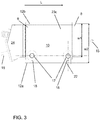
- FIG 3 illustrates a top view of the heat exchanger.
- the circles in the Figure 3 represent a cooling fluid circulating devices 5 in the mounting spots 17.
- Two cooling fluid circulating devices 5 are located one after the other in the length direction of the heat exchanger L.
- the cooling fluid circulating devices 5 are in the same half of the heat exchanger 1 in the direction of the width of the heat exchanger w.
- the heat exchanger 1 and an external fan unit 24 for transferring an external cooling fluid 15 in the plurality of tubes 7 form a cooling unit of the electrical machine 2.
- the flow direction of the external cooling fluid 15 is from the first end of the heat exchanger 8 to the second end 9, where the first end corresponds the drive end side of the electrical machine 2 and the second end corresponds the non-drive end of the electrical machine 2.
- the external fan unit 24 is located adjacent to the second end 9 of the heat exchanger 1.
- the flow direction of the external cooling fluid 15 may be also from the second end 9 of the heat exchanger 1 to the first end 8 of the heat exchanger 1, and the external fan unit 24 may located adjacent to the first 8 or second end 9 of the heat exchanger 1.
- the horizontal baffle 23c above one mounting spot 17 is shown with a dotted line.
- the electrical machine 2 in the figures is a wind turbine generator, which can be placed in a nacelle of a wind turbine to convert mechanical power into electricity.
- the external cooling fluid 15 is a gas, e.g. air. If the external cooling fluid 15 flowing in the tube bundle is liquid then the cooling unit comprises an external pump unit for transferring an external cooling fluid 15 in the plurality of tubes 7. With a liquid as an external cooling fluid 15 it is preferred that the plurality of tubes 7 comprise double tubes where a primary tube is inserted in a secondary tube. If the primary tube starts leaking the leaking external cooling fluid 15 flows between the primary and secondary tubes into a leakage collection space and the leakage is kept separate from the cooling fluid flowing in the housing.
- a gas e.g. air.
- a heat exchanger housing 6 comprising a top wall 10, end walls 11a-b extending in the direction of the width of the heat exchanger w and side walls 12a-b extending in the direction of the length of the heat exchanger L and a bottom frame 13 is manufactured.
- a tube bundle 3 comprising a plurality of tubes 7 is manufactured.
- the plurality of tubes 7 is arranged within the housing 6 to extend between a first end 8 and a second end 9 of the housing 6 in the direction of the length of the heat exchanger L.
- a mounting space 4 for receiving one or more cooling fluid circulating devices 5.
- the heat exchanger 1 for an electrical machine 2 is flat as the cooling fluid circulating devices 5 are located within the housing 6.
- the maintenance and possible replacement of the cooling fluid circulating devices 5 can be made from the side 12a of the heat exchanger 1. As there is no need to lift up the cooling fluid circulating devices 5 during the maintenance the required free height above the heat exchanger 1 is minimized.
- the heat exchanger 1 is suitable to be installed in the nacelle of a wind turbine, for instance.
- the heat exchanger 1 is suitable for other applications requiring compact size from a cooling unit and its heat exchangers 1.
- the cooling fluid circulating device 5 is a fan 18 comprising a fan motor 20 and a fan wheel 19.
- the heat exchanger 1 comprises two cooling fluid circulating devices 5 located one after the other in the length direction of the heat exchanger L in the same half of the heat exchanger in the direction of the width of the heat exchanger.
- the plurality of tubes 7 comprise double tubes where a primary tube is inserted in a secondary tube.
- the electrical machine 2 comprises a side mounted terminal box 22 on a frame of the electrical machine, and the terminal box 22 and the first side wall 12a of the heat exchanger 1 are on the same side of the assembly of heat exchanger 1 and the electrical machine 2.
- h1 an internal height of the housing, h2 a height of the tube bundle, L a the length of the heat exchanger, w a width of the heat exchanger, w1 width of the housing at the bottom frame, w2 width of a housing, w3 width of a tube bundle, y vertical direction.
Description
- The invention relates to a heat exchanger for an electrical machine.
- An electrical machine generates heat in its various parts because of mechanical losses, magnetic losses and electrical losses. This excess heat has to be removed. The heat is often transferred to a cooling fluid which is circulated in the electrical machine and then cooled in a separate cooling unit after which it is returned back to the electrical machine.
- In applications like wind turbine generator systems the space is precious. A wind turbine nacelle has compact dimensions and place requirements on the size of the cooling unit and its heat exchangers.
- A heat exchanger for cooling an electrical machine is typically installed on the top of the electrical machine increasing the total height of the wind turbine generator. The cooling fluid circulation of the electrical machine needs often also fans or pumps to enhance the cooling fluid circulation in the heat exchanger. These fans or pumps also increase the required free height in the nacelle.
- The drawback with the previous solutions in a heat exchanger for the electrical machine is its requirements for the space and the free height.
-
DE 10 2006 024 342 discloses a heat exchanger. The heat-exchanger has a housing comprising a central region and two edge regions, an inner circuit for heated air to be cooled and an outer circuit, formed as flow-channels for cool air. In the central region, the flow channels of the inner circuit or the outer circuit extend mainly parallel to one another, and in the edge regions a space for a fan is provided which is arranged underneath the inlet or outlet so that the fan is integrated in the housing. -
US 2011/0000640 discloses a wind turbine generator with a heat exchanger. The heat exchanger comprises a primary and a secondary cooling circuit, arranged for circulating a first and a second fluid, respectively between the heat-generating source and the heat exchanger, and a cooling reservoir and the heat exchanger, respectively. The heat exchanger comprises a plurality of pipes for conveying the second fluid from the secondary cooling circuit through the heat exchanger. The plurality of pipes is arranged for heat exchange with a flow of the first fluid from the primary cooling circuit. The secondary cooling circuit further comprises a dispersion chamber connected to the plurality of pipes. The dispersion chamber has a fluid intake being positioned sideways relative to the plurality of pipes so as to provide, at least partly, a levelling of the flow distribution across the plurality of pipes of the second fluid prior to heat exchange. -
DE 42 13 509 discloses a heat exchanger for a condenser of a vehicle air conditioning system. The heat exchanger has a number of parallel tubes for circulating a cooling fluid. The tubes are grouped as U-shaped pairs. They extend at right angles from a tubular casing with two chambers, one with an inlet union from the system, the other with an outlet union to the rest of the system. One leg of each pair of pipes is connected to the inlet chamber, the other leg to the outlet chamber. The wall separating the two chambers is offset from a diametral plane so that the inlet chamber has a larger cross-section than the outlet one. -
FR 2 771 481 - An object of the present invention is to solve the above mentioned drawbacks and to provide a compact heat exchanger for an electrical machine.
- This object is achieved with a heat exchanger according to
independent claim 1. - A heat exchanger for an electrical machine comprises a housing and a tube bundle. The tube bundle comprises a plurality of tubes within the housing extending between a first end and a second end of the housing in the direction of the length of the heat exchanger. The housing comprises a top wall, end walls extending in the direction of the width of the heat exchanger and first and second side walls extending in the direction of the length of the heat exchanger and a bottom frame. Between a first side wall of the housing and a side wall of the tube bundle is a mounting space extending from the first end to the second end of the housing, a first fan being positioned in the mounting space adjacent to the first end of the housing and a second fan being positioned in the mounting space adjacent to the second end of the housing. The first fan and the second fan are located one after the other in the length direction of the heat exchanger in the same half of the heat exchanger in the direction of the width of the heat exchanger.
- An advantage of the invention is that it reduces the required space and the free height for the heat exchanger.
- Some preferred embodiments of the invention are disclosed in the dependent claims.
- In the following the invention will be described in greater detail by means of preferred embodiments with reference to the accompanying drawings, in which
-
Figure 1 shows an end view of a heat exchanger connected to an electrical machine; -
Figure 2 shows a side view of the heat exchanger connected to an electrical machine; -
Figure 3 shows a top view of the heat exchanger connected to an electrical machine. -
Figure 1 shows an end view of aheat exchanger 1 connected to anelectrical machine 2. In theFigure 1 the end wall of the heat exchanger is removed in order to better illustrate the arrangement of atube bundle 3, amounting space 4 and a coolingfluid circulating device 5 within theheat exchanger housing 6. - The
heat exchanger 1 comprises ahousing 6 and atube bundle 3. Thetube bundle 3 comprises a plurality oftubes 7 within thehousing 6 extending between afirst end 8 and asecond end 9 of thehousing 6 in the direction of the length of the heat exchanger L. The outer surface of a tube can be finned, for instance, for enhancing the heat transfer between the tube surface and a cooling fluid flowing over the tube surface. Thehousing 6 comprises atop wall 10, end walls 11 extending in the direction of the width w of the heat exchanger and first 12a andsecond side walls 12b extending in the direction of the length of the heat exchanger L and abottom frame 13. Thecooling fluid 14, i.e. theinternal cooling fluid 14, flowing in the housing over the plurality oftubes 7 enters and exits through thebottom frame 13 through one or more openings formed in the bottom frame. Theexternal cooling fluid 15 flowing in the plurality oftubes 7 enters through afirst end wall 11a and exits through asecond end wall 11b through one or more openings. - Between a first side wall of the
housing 12a and the side oftube bundle 16 is amounting space 4. The mounting space extends from thefirst end 8 to the second end of theheat exchanger 9. In theFigure 1 the width of the tube bundle w3 is wider in the region closer to thebottom frame 13 than the width of the tube bundle w3 in a region closer to thetop wall 10 creating amounting space 17 between a first side wall of thehousing 12a and a side of thetube bundle 16. However, the width of the tube bundle w3 may remain also constant or vary in the height direction. Thetube bundle 3 preferably extends to thesecond side wall 12b of theheat exchanger 1 in order maximize the heat transfer surface of the plurality oftubes 7 within thehousing 6. - The vertically lower part of the
mounting space 4 is abutted on the plurality of thetubes 7 and thefirst side wall 12a. Thetube bundle 3 extends to thefirst side wall 12a below the vertically lower part of themounting space 4 in the width direction w. It is also possible that thetube bundle 3 does not extend to thefirst side wall 12a below the vertically lower part of themounting space 4 in the width direction w leaving the lower part ofmounting space 4 open towards thebottom frame 13. - The
mounting space 4 may comprise one ormore mounting spots 17 of a coolingfluid circulating device 5 having mounting faces for the coolingfluid circulating devices 5. - The height of the tube bundle h2 is less than the internal height of the housing h1. The height of the tube bundle h2 is preferably 50-80% of the internal height of the housing h1 in vertical direction y. The height of the tube bundle h2 may also be arranged to extend to the
horizontal baffle 23c. The upper part of theheat exchanger 1 is left without plurality oftubes 7 arranged in rows in order to create a free passage for the coolingfluid 14 in the length direction of the heat exchanger L to reach one or more coolingfluid circulating device 5. - The width of the housing may be 5-25% greater in the top wall region w2 than the width of the housing in the bottom frame region w1. The greater width of the housing on the
first side wall 12a side of thehousing 6 in the upper part of theheat exchanger 1 provides more space for installing one or more coolingfluid circulating devices 5. In the figures thefan wheel 19 is placed to the top wall region having greater width of 8-15% and thefan motor 20 is placed to the middle region having a smaller width of the housing w than in thetop wall 10 region. - The cooling
fluids electrical machine 2 for heat exchange are typically gaseous and/or liquid, e.g. air and water.Electrical machines 2 used as wind turbine generators use often air as the coolingfluid 14 within the electrical machine, i.e. in the internal circulation, and air or water as anexternal cooling fluid 15 in the external circulation which cools down the air of internal circulation. Then the coolingfluid 14 flowing over the tubes within the housing is gaseous and theexternal cooling fluid 15 flowing inside the tubes is gaseous or liquid. In theheat exchanger 1 the coolingfluid 14 transfers heat to theexternal cooling fluid 15 through the tube walls and cools down. - The cooling fluid circulating
device 5 can comprise afan 18, for instance. In the figures the cooling fluid circulatingdevice 5 comprises afan 18 comprising afan motor 20 and afan wheel 19. Thefan 18 is mounted in the mountingspace 4 and afan wheel 19 of the fan is positioned above thefan motor 20 in vertical direction y. The inlet of thefan wheel 19 is above the plurality of thetubes 7 in vertical direction y. Thefan wheel 19 can be linked directly to the shaft of anelectric motor 20. - The
heat exchanger 1 may be installed on the top of anelectrical machine 2. Theelectrical machine 2 shown has a symmetrical cooling fluid circulation where the cooling fluid enters to theelectrical machine 2 from its both ends and in the electrical machine heated cooling fluid exits from the middle part of theelectrical machine 2. Theheat exchanger 1 is attached to a frame of theelectrical machine 21 by means of thebottom frame 13. - The electrical machine may comprise a side mounted
terminal box 22 on a frame of theelectrical machine 21. Then theterminal box 22 and the first side wall of theheat exchanger 12a are preferably on the same side of the assembly of theelectrical machine 2 and theheat exchanger 1. This arrangement is advantageous as the maintenance and possible replacement of the cooling fluid circulatingdevices 5 can be performed using the same catwalks and other structures provided for theterminal box 22. -
Figure 2 shows a side view of theheat exchanger 1 connected to anelectrical machine 2. Theheat exchanger 1 is shown with thefirst side wall 12a removed and thetube bundle 3 is presented as a transparent square for the sake of clarity. - The
heat exchanger 1 comprisesbaffles 23a-c within the housing which divide the heat exchanger into sections. Thebaffles 23a-c can be designed also to support the tubes but thebaffles 23a-c may only be used as a coolingfluid flow 14 directors. Thebaffles 23a-c are arranged to form fluid channels for the coolingfluid flow 14. - The heat exchanger shown in
Figure 2 comprisesbaffles 23a-b spaced at a distance apart from each other in the length direction of the heat exchanger L. Two inlet baffles 23a are located between two mountingspots 17, i.e. between the cooling fluid circulatingdevices 5, forming a cooling fluid inlet flow channel in the middle part of theheat exchanger 1. The cooling fluid inlet flow channel extends from thebottom frame 13 to above the plurality of thetubes 7. - Two outlet baffles 23b are located on the sides of the two mounting
spots 17, i.e. between the cooling fluid circulatingdevices 5, facing the first 8 andsecond end 9 of theheat exchanger 1. The inlet baffles 23a in the middle part of theheat exchanger 1 and the outlet baffles 23b at thefirst end 8 part region and thesecond end 9 part region of theheat exchanger 1 form cooling fluid outlet flow channels in the vertical direction of the heat exchanger y. - Above a mounting
spot 17 is ahorizontal baffle 23c with an opening for the coolingfluid flow 14. Thehorizontal baffle 23c and thetop wall 10 form a cooling fluid channel in the length direction of the heat exchanger L. Thehorizontal baffle 23c extends preferably between the first 12a andsecond side 12b walls and is attached to aninlet 23a andoutlet baffle 23b creating a cover to the cooling fluid outlet flow channel. - The small and big arrows indicate the flow direction of the cooling
fluid 14. Thefan 18 is configured to suck the coolingfluid 14 through the cooling fluid inlet flow channel formed in the middle part of theheat exchanger 1. The coolingfluid 14 cools in the inlet flow channel as it flows over the plurality oftubes 7. The coolingfluid 14 is further sucked through the cooling fluid channels in the length direction of the heat exchanger L in the upper part of theheat exchanger 1 towards the ends of thehousing fluid 14 enters then to thefan wheel 19 via its inlet and is pushed through the cooling fluid outlet flow channels formed at thefirst end 8 part region and thesecond end 9 part region of theheat exchanger 1. - The outlet of the
fan wheel 19 may be configured to blow the coolingfluid 14 towards thetube bundle 3 in the width direction of the tube bundle w. -
Figure 3 illustrates a top view of the heat exchanger. The circles in theFigure 3 represent a cooling fluid circulatingdevices 5 in the mounting spots 17. Two cooling fluid circulatingdevices 5 are located one after the other in the length direction of the heat exchanger L. The cooling fluid circulatingdevices 5 are in the same half of theheat exchanger 1 in the direction of the width of the heat exchanger w. - The
heat exchanger 1 and anexternal fan unit 24 for transferring anexternal cooling fluid 15 in the plurality oftubes 7 form a cooling unit of theelectrical machine 2. In the Figures the flow direction of theexternal cooling fluid 15 is from the first end of theheat exchanger 8 to thesecond end 9, where the first end corresponds the drive end side of theelectrical machine 2 and the second end corresponds the non-drive end of theelectrical machine 2. Theexternal fan unit 24 is located adjacent to thesecond end 9 of theheat exchanger 1. However, the flow direction of theexternal cooling fluid 15 may be also from thesecond end 9 of theheat exchanger 1 to thefirst end 8 of theheat exchanger 1, and theexternal fan unit 24 may located adjacent to the first 8 orsecond end 9 of theheat exchanger 1. - The
horizontal baffle 23c above one mountingspot 17 is shown with a dotted line. - The
electrical machine 2 in the figures is a wind turbine generator, which can be placed in a nacelle of a wind turbine to convert mechanical power into electricity. - In the Figures the
external cooling fluid 15 is a gas, e.g. air. If theexternal cooling fluid 15 flowing in the tube bundle is liquid then the cooling unit comprises an external pump unit for transferring anexternal cooling fluid 15 in the plurality oftubes 7. With a liquid as anexternal cooling fluid 15 it is preferred that the plurality oftubes 7 comprise double tubes where a primary tube is inserted in a secondary tube. If the primary tube starts leaking the leakingexternal cooling fluid 15 flows between the primary and secondary tubes into a leakage collection space and the leakage is kept separate from the cooling fluid flowing in the housing. - In the method for manufacturing a
heat exchanger 1 for an electrical machine 2 aheat exchanger housing 6 comprising atop wall 10,end walls 11a-b extending in the direction of the width of the heat exchanger w andside walls 12a-b extending in the direction of the length of the heat exchanger L and abottom frame 13 is manufactured. Atube bundle 3 comprising a plurality oftubes 7 is manufactured. The plurality oftubes 7 is arranged within thehousing 6 to extend between afirst end 8 and asecond end 9 of thehousing 6 in the direction of the length of the heat exchanger L. Between afirst side wall 12a of thehousing 6 and a side of thetube bundle 16 is arranged a mountingspace 4 for receiving one or more coolingfluid circulating devices 5. - The
heat exchanger 1 for anelectrical machine 2 is flat as the cooling fluid circulatingdevices 5 are located within thehousing 6. The maintenance and possible replacement of the cooling fluid circulatingdevices 5 can be made from theside 12a of theheat exchanger 1. As there is no need to lift up the cooling fluid circulatingdevices 5 during the maintenance the required free height above theheat exchanger 1 is minimized. Theheat exchanger 1 is suitable to be installed in the nacelle of a wind turbine, for instance. Theheat exchanger 1 is suitable for other applications requiring compact size from a cooling unit and itsheat exchangers 1. - The cooling fluid circulating
device 5 is afan 18 comprising afan motor 20 and afan wheel 19. - The
heat exchanger 1 comprises two coolingfluid circulating devices 5 located one after the other in the length direction of the heat exchanger L in the same half of the heat exchanger in the direction of the width of the heat exchanger. - The plurality of
tubes 7 comprise double tubes where a primary tube is inserted in a secondary tube. - The
electrical machine 2 comprises a side mountedterminal box 22 on a frame of the electrical machine, and theterminal box 22 and thefirst side wall 12a of theheat exchanger 1 are on the same side of the assembly ofheat exchanger 1 and theelectrical machine 2. - It will be obvious to a person skilled in the art that, as the technology advances, the inventive concept can be implemented in various ways. The invention and its embodiments are not limited to the examples described above but may vary within the scope of the claims.
- Part list: 1 a heat exchanger, 2 an electrical machine, 3 a tube bundle, 4 a mounting space, 5 a cooling fluid circulating device, 6 a housing, 7 a plurality of tubes, 8 a first end, 9 a second end, 10 a top wall, 11a a first end wall, 11b a second end wall, 12a a first side wall, 12 b a second side wall, 13 a bottom frame, 14 a cooling fluid flow, 15 an external cooling fluid flow, 16 a side of the tube bundle, 17 a mounting spot, 18 fan, 19 a fan wheel, 20 a fan motor, 21 a frame of an electrical machine, 22 a terminal box, 23a-c a baffle, 24 an external fan unit.
- h1 an internal height of the housing, h2 a height of the tube bundle, L a the length of the heat exchanger, w a width of the heat exchanger, w1 width of the housing at the bottom frame, w2 width of a housing, w3 width of a tube bundle, y vertical direction.
Claims (15)
- A heat exchanger (1) for an electrical machine (2), where the heat exchanger (1) comprises a housing (6) and a tube bundle (3), the tube bundle (3) comprising a plurality of tubes (7) within the housing (6) extending between a first end (8) and a second end (9) of the housing (6) in the direction of the length (L) of the heat exchanger (1), the housing (6) comprises a top wall (10), end walls (11a-b) extending in the direction of the width (w) of the heat exchanger (1) and first (12a) and second side walls (12b) extending in the direction of the length (L) of the heat exchanger (1) and a bottom frame (13), characterized in that between a first side wall (12a) of the housing (6) and a side of the tube bundle (16) within the housing is a mounting space (4) extending from the first end (8) to the second end (9) of the housing (6), a first fan (18) being positioned in the mounting space (4) adjacent to the first end (8) of the housing (6) and a second fan (18) being positioned in the mounting space (4) adjacent to the second end (9) of the housing (6), the first fan (18) and the second fan (18) being located one after the other in the length direction (L) of the heat exchanger (1) in the same half of the heat exchanger (1) in the direction of the width (w) of the heat exchanger (1).
- The heat exchanger for an electrical machine according to claim 1, characterized in that the fan wheel (19) of each fan (18) is positioned above the fan motor (20) of each fan in the vertical direction (y).
- The heat exchanger for an electrical machine according to claim 2, characterized in that an inlet of each fan wheel (19) is above the plurality of the tubes (7) in the vertical direction (y).
- The heat exchanger for an electrical machine as claimed in any one of claims 1 to 3, characterized in that the heat exchanger (1) comprises baffles (23a-b) spaced at a distance apart from each other in the length direction of the heat exchanger (L), whereby at least two of the baffles (23a-b) are inlet baffles (23a) located between the fans (18) forming a cooling fluid inlet flow channel in the vertical direction of the heat exchanger (y).
- The heat exchanger for an electrical machine according to claim 4, characterized in that at least two outlet baffles (23b) are located on the sides of the fans (18) facing the first (8) and second end (9) of the heat exchanger (1), and the at least two inlet (23a) and outlet baffles (23b) form cooling fluid outlet flow channels in the vertical direction of the heat exchanger (y).
- The heat exchanger for an electrical machine according to the claim 5, characterized in that the fans (18) are configured to suck cooling fluid (14) through a cooling fluid inlet flow channel formed in the middle part of the heat exchanger (1) and to blow the cooling fluid (14) through cooling fluid outlet flow channels formed at the first end (8) part region and the second end (9) part region of the heat exchanger (1).
- The heat exchanger for an electrical machine as claimed in any one of claims 1 to 6, characterized in that the outlet of the fans (18) are configured to blow the cooling fluid (14) towards the tube bundle (3) in the width direction of the tube bundle (w).
- The heat exchanger for an electrical machine as claimed in any one of claims 1 to 7, characterized in that the height of the tube bundle (h2) is 50-80% of the internal height of the housing (h1) in the vertical direction (y).
- The heat exchanger for an electrical machine as claimed in any one of claims 1 to 8, characterized in that the width of the tube bundle (w3) is wider in the region closer to the bottom frame (13) than the width of the tube bundle in a region closer to the top wall (10).
- The heat exchanger for an electrical machine as claimed in any one of claims 1 to 9, characterized in that the tube bundle (3) extends to the first side wall (12a) below the vertically lower part of the mounting space (4) in the width direction w.
- The heat exchanger for an electrical machine as claimed in any one of claims 1 to 10, characterized in that the width of the housing (w2) is 5-25% greater in the top wall region than the width of the housing (w1) in the bottom frame (13) region.
- A cooling unit of an electrical machine comprising a heat exchanger as claimed in any one of the preceding claims, characterized in that the heat exchanger (1) comprises an external fan unit (24) for transferring an external cooling fluid in the plurality of tubes (7).
- An electrical machine comprising a heat exchanger as claimed in any one of claims 1-12, characterized in that the heat exchanger (1) is installed on the top of an electrical machine (2) and is attached to a frame of the electrical machine by means of the bottom frame (13).
- An electrical machine as claimed in claim 13, characterized in that the electrical machine (2) comprises a wind turbine generator.
- A wind turbine comprising an electrical machine according to any one of claims 13-14.
Applications Claiming Priority (2)
| Application Number | Priority Date | Filing Date | Title |
|---|---|---|---|
| CN201610371050.XA CN107453546A (en) | 2016-05-30 | 2016-05-30 | Heat exchanger for motor |
| PCT/EP2017/062984 WO2017207537A1 (en) | 2016-05-30 | 2017-05-30 | A heat exchanger for an electrical machine |
Publications (2)
| Publication Number | Publication Date |
|---|---|
| EP3465047A1 EP3465047A1 (en) | 2019-04-10 |
| EP3465047B1 true EP3465047B1 (en) | 2020-12-16 |
Family
ID=58800826
Family Applications (1)
| Application Number | Title | Priority Date | Filing Date |
|---|---|---|---|
| EP17726620.2A Active EP3465047B1 (en) | 2016-05-30 | 2017-05-30 | A heat exchanger for an electrical machine |
Country Status (5)
| Country | Link |
|---|---|
| US (1) | US10753343B2 (en) |
| EP (1) | EP3465047B1 (en) |
| CN (1) | CN107453546A (en) |
| ES (1) | ES2848579T3 (en) |
| WO (1) | WO2017207537A1 (en) |
Families Citing this family (2)
| Publication number | Priority date | Publication date | Assignee | Title |
|---|---|---|---|---|
| EP3908748A1 (en) * | 2019-01-10 | 2021-11-17 | Vestas Wind Systems A/S | Improvements relating to cooling of electrical generators in wind turbines |
| CN109779854B (en) * | 2019-03-07 | 2020-05-05 | 惠安佳瑞汽车销售服务有限公司 | Cooling and heat radiating device for bearing wind driven generator |
Family Cites Families (11)
| Publication number | Priority date | Publication date | Assignee | Title |
|---|---|---|---|---|
| DE4213509A1 (en) * | 1992-04-24 | 1993-10-28 | Audi Ag | Heat exchanger for condenser of vehicle air conditioning system - has parallel pairs of U=shaped tubes joined to tubular casing divided into inlet and outlet chambers |
| FR2771481B1 (en) * | 1997-11-24 | 2000-01-28 | Valeo Thermique Moteur Sa | PROFILE HEAT EXCHANGER, PARTICULARLY FOR A MOTOR VEHICLE |
| DE10233947A1 (en) * | 2002-07-25 | 2004-02-12 | Siemens Ag | Wind power system has generator in gondola, turbine with rotor blade(s); generator has a closed primary cooling circuit; the gondola has an arrangement enabling cooling of primary cooling circuit |
| EP1447899A1 (en) * | 2003-02-13 | 2004-08-18 | Loher GmbH | Dynamoelectric machine |
| CA2443496C (en) * | 2003-09-30 | 2011-10-11 | Dana Canada Corporation | Tube bundle heat exchanger comprising tubes with expanded sections |
| DE102006024342A1 (en) * | 2006-05-24 | 2007-11-29 | Wantschik, Michael, Dr. | Heat exchanger e.g. for electronics cubicle, has cooled air outer circuit formed as flow channels arranged parallel to one another |
| CN101042289A (en) * | 2007-04-26 | 2007-09-26 | 宋小平 | Setups modus of short-circuit-proof spiral baffle plate shell-and-tube heat exchanger draw rod |
| EP2238345B1 (en) * | 2007-12-21 | 2011-06-01 | Vestas Wind Systems A/S | A wind turbine generator with a heat exchanger |
| US20110132575A1 (en) * | 2009-12-07 | 2011-06-09 | Goodson J Michael | Cleaning Industrial Heat Exchangers Through Utilization of Thicknenss Mode Ultrasonics |
| US20150144308A1 (en) * | 2015-02-03 | 2015-05-28 | Caterpillar Inc. | Baffle assembly for heat exchanger |
| CN205992834U (en) * | 2016-05-30 | 2017-03-01 | Abb技术有限公司 | For the heat exchanger of motor, the cooling unit of motor, motor and wind turbine |
-
2016
- 2016-05-30 CN CN201610371050.XA patent/CN107453546A/en active Pending
-
2017
- 2017-05-30 ES ES17726620T patent/ES2848579T3/en active Active
- 2017-05-30 EP EP17726620.2A patent/EP3465047B1/en active Active
- 2017-05-30 WO PCT/EP2017/062984 patent/WO2017207537A1/en unknown
-
2018
- 2018-11-30 US US16/206,101 patent/US10753343B2/en active Active
Non-Patent Citations (1)
| Title |
|---|
| None * |
Also Published As
| Publication number | Publication date |
|---|---|
| US20190101105A1 (en) | 2019-04-04 |
| EP3465047A1 (en) | 2019-04-10 |
| CN107453546A (en) | 2017-12-08 |
| ES2848579T3 (en) | 2021-08-10 |
| WO2017207537A1 (en) | 2017-12-07 |
| US10753343B2 (en) | 2020-08-25 |
Similar Documents
| Publication | Publication Date | Title |
|---|---|---|
| US9939183B2 (en) | Constant-temperature-fluid circulation device | |
| US20110272120A1 (en) | Compact modular liquid cooling systems for electronics | |
| CN103229013B (en) | The cooling of motor | |
| CN108801010B (en) | Loop heat pipe steam generator with large heat exchange area | |
| EP2171385A2 (en) | Auxiliary cooling system | |
| CN102187549A (en) | Dynamoelectric machine | |
| EP3091826A2 (en) | Thermal control system for closed electronic platform | |
| EP3465047B1 (en) | A heat exchanger for an electrical machine | |
| JP6283277B2 (en) | Air conditioning equipment for server systems | |
| EP3904818B1 (en) | Electric arrangement comprising a heat exchanger | |
| CN212989598U (en) | Fuel cell test platform cooling system | |
| CN201388355Y (en) | Heat dissipating device and electronic part module box and machine room with heat dissipating devices | |
| CN209840293U (en) | Outdoor unit and air conditioner with same | |
| CN203689298U (en) | Liquid-cooled heat dissipation device | |
| CN210425661U (en) | Energy-saving cooling equipment with overhead evaporation cooling coil | |
| CN205992834U (en) | For the heat exchanger of motor, the cooling unit of motor, motor and wind turbine | |
| CN218940837U (en) | High temperature prevention device for motor winding | |
| CN215073604U (en) | Liquid-electricity separated liquid cooling heat dissipation system for laser television | |
| CN217585453U (en) | Drainage cooling device | |
| CN213151794U (en) | Air-water cooler of wind power generator | |
| CN216522101U (en) | Dehumidifier | |
| CN217685493U (en) | Air conditioner outdoor unit and air conditioner | |
| KR102540887B1 (en) | Cooling apparatus for vehicle having fuel cell | |
| CN218897417U (en) | Water-oil composite cooler | |
| US20230168000A1 (en) | Air conditioning apparatus and electric control box |
Legal Events
| Date | Code | Title | Description |
|---|---|---|---|
| STAA | Information on the status of an ep patent application or granted ep patent |
Free format text: STATUS: UNKNOWN |
|
| STAA | Information on the status of an ep patent application or granted ep patent |
Free format text: STATUS: THE INTERNATIONAL PUBLICATION HAS BEEN MADE |
|
| PUAI | Public reference made under article 153(3) epc to a published international application that has entered the european phase |
Free format text: ORIGINAL CODE: 0009012 |
|
| STAA | Information on the status of an ep patent application or granted ep patent |
Free format text: STATUS: REQUEST FOR EXAMINATION WAS MADE |
|
| 17P | Request for examination filed |
Effective date: 20181116 |
|
| AK | Designated contracting states |
Kind code of ref document: A1 Designated state(s): AL AT BE BG CH CY CZ DE DK EE ES FI FR GB GR HR HU IE IS IT LI LT LU LV MC MK MT NL NO PL PT RO RS SE SI SK SM TR |
|
| AX | Request for extension of the european patent |
Extension state: BA ME |
|
| DAV | Request for validation of the european patent (deleted) | ||
| DAX | Request for extension of the european patent (deleted) | ||
| STAA | Information on the status of an ep patent application or granted ep patent |
Free format text: STATUS: EXAMINATION IS IN PROGRESS |
|
| 17Q | First examination report despatched |
Effective date: 20191202 |
|
| GRAJ | Information related to disapproval of communication of intention to grant by the applicant or resumption of examination proceedings by the epo deleted |
Free format text: ORIGINAL CODE: EPIDOSDIGR1 |
|
| GRAP | Despatch of communication of intention to grant a patent |
Free format text: ORIGINAL CODE: EPIDOSNIGR1 |
|
| GRAP | Despatch of communication of intention to grant a patent |
Free format text: ORIGINAL CODE: EPIDOSNIGR1 |
|
| STAA | Information on the status of an ep patent application or granted ep patent |
Free format text: STATUS: GRANT OF PATENT IS INTENDED |
|
| INTG | Intention to grant announced |
Effective date: 20200710 |
|
| RAP1 | Party data changed (applicant data changed or rights of an application transferred) |
Owner name: ABB SCHWEIZ AG |
|
| GRAS | Grant fee paid |
Free format text: ORIGINAL CODE: EPIDOSNIGR3 |
|
| GRAA | (expected) grant |
Free format text: ORIGINAL CODE: 0009210 |
|
| STAA | Information on the status of an ep patent application or granted ep patent |
Free format text: STATUS: THE PATENT HAS BEEN GRANTED |
|
| AK | Designated contracting states |
Kind code of ref document: B1 Designated state(s): AL AT BE BG CH CY CZ DE DK EE ES FI FR GB GR HR HU IE IS IT LI LT LU LV MC MK MT NL NO PL PT RO RS SE SI SK SM TR |
|
| REG | Reference to a national code |
Ref country code: GB Ref legal event code: FG4D |
|
| REG | Reference to a national code |
Ref country code: DE Ref legal event code: R096 Ref document number: 602017029608 Country of ref document: DE |
|
| REG | Reference to a national code |
Ref country code: IE Ref legal event code: FG4D |
|
| REG | Reference to a national code |
Ref country code: AT Ref legal event code: REF Ref document number: 1345970 Country of ref document: AT Kind code of ref document: T Effective date: 20210115 |
|
| PG25 | Lapsed in a contracting state [announced via postgrant information from national office to epo] |
Ref country code: GR Free format text: LAPSE BECAUSE OF FAILURE TO SUBMIT A TRANSLATION OF THE DESCRIPTION OR TO PAY THE FEE WITHIN THE PRESCRIBED TIME-LIMIT Effective date: 20210317 Ref country code: FI Free format text: LAPSE BECAUSE OF FAILURE TO SUBMIT A TRANSLATION OF THE DESCRIPTION OR TO PAY THE FEE WITHIN THE PRESCRIBED TIME-LIMIT Effective date: 20201216 Ref country code: RS Free format text: LAPSE BECAUSE OF FAILURE TO SUBMIT A TRANSLATION OF THE DESCRIPTION OR TO PAY THE FEE WITHIN THE PRESCRIBED TIME-LIMIT Effective date: 20201216 Ref country code: NO Free format text: LAPSE BECAUSE OF FAILURE TO SUBMIT A TRANSLATION OF THE DESCRIPTION OR TO PAY THE FEE WITHIN THE PRESCRIBED TIME-LIMIT Effective date: 20210316 |
|
| REG | Reference to a national code |
Ref country code: AT Ref legal event code: MK05 Ref document number: 1345970 Country of ref document: AT Kind code of ref document: T Effective date: 20201216 |
|
| REG | Reference to a national code |
Ref country code: NL Ref legal event code: MP Effective date: 20201216 |
|
| PG25 | Lapsed in a contracting state [announced via postgrant information from national office to epo] |
Ref country code: SE Free format text: LAPSE BECAUSE OF FAILURE TO SUBMIT A TRANSLATION OF THE DESCRIPTION OR TO PAY THE FEE WITHIN THE PRESCRIBED TIME-LIMIT Effective date: 20201216 Ref country code: LV Free format text: LAPSE BECAUSE OF FAILURE TO SUBMIT A TRANSLATION OF THE DESCRIPTION OR TO PAY THE FEE WITHIN THE PRESCRIBED TIME-LIMIT Effective date: 20201216 Ref country code: BG Free format text: LAPSE BECAUSE OF FAILURE TO SUBMIT A TRANSLATION OF THE DESCRIPTION OR TO PAY THE FEE WITHIN THE PRESCRIBED TIME-LIMIT Effective date: 20210316 |
|
| PG25 | Lapsed in a contracting state [announced via postgrant information from national office to epo] |
Ref country code: NL Free format text: LAPSE BECAUSE OF FAILURE TO SUBMIT A TRANSLATION OF THE DESCRIPTION OR TO PAY THE FEE WITHIN THE PRESCRIBED TIME-LIMIT Effective date: 20201216 Ref country code: HR Free format text: LAPSE BECAUSE OF FAILURE TO SUBMIT A TRANSLATION OF THE DESCRIPTION OR TO PAY THE FEE WITHIN THE PRESCRIBED TIME-LIMIT Effective date: 20201216 |
|
| REG | Reference to a national code |
Ref country code: LT Ref legal event code: MG9D |
|
| PG25 | Lapsed in a contracting state [announced via postgrant information from national office to epo] |
Ref country code: PT Free format text: LAPSE BECAUSE OF FAILURE TO SUBMIT A TRANSLATION OF THE DESCRIPTION OR TO PAY THE FEE WITHIN THE PRESCRIBED TIME-LIMIT Effective date: 20210416 Ref country code: SK Free format text: LAPSE BECAUSE OF FAILURE TO SUBMIT A TRANSLATION OF THE DESCRIPTION OR TO PAY THE FEE WITHIN THE PRESCRIBED TIME-LIMIT Effective date: 20201216 Ref country code: RO Free format text: LAPSE BECAUSE OF FAILURE TO SUBMIT A TRANSLATION OF THE DESCRIPTION OR TO PAY THE FEE WITHIN THE PRESCRIBED TIME-LIMIT Effective date: 20201216 Ref country code: EE Free format text: LAPSE BECAUSE OF FAILURE TO SUBMIT A TRANSLATION OF THE DESCRIPTION OR TO PAY THE FEE WITHIN THE PRESCRIBED TIME-LIMIT Effective date: 20201216 Ref country code: CZ Free format text: LAPSE BECAUSE OF FAILURE TO SUBMIT A TRANSLATION OF THE DESCRIPTION OR TO PAY THE FEE WITHIN THE PRESCRIBED TIME-LIMIT Effective date: 20201216 Ref country code: LT Free format text: LAPSE BECAUSE OF FAILURE TO SUBMIT A TRANSLATION OF THE DESCRIPTION OR TO PAY THE FEE WITHIN THE PRESCRIBED TIME-LIMIT Effective date: 20201216 Ref country code: SM Free format text: LAPSE BECAUSE OF FAILURE TO SUBMIT A TRANSLATION OF THE DESCRIPTION OR TO PAY THE FEE WITHIN THE PRESCRIBED TIME-LIMIT Effective date: 20201216 |
|
| REG | Reference to a national code |
Ref country code: ES Ref legal event code: FG2A Ref document number: 2848579 Country of ref document: ES Kind code of ref document: T3 Effective date: 20210810 |
|
| PG25 | Lapsed in a contracting state [announced via postgrant information from national office to epo] |
Ref country code: AT Free format text: LAPSE BECAUSE OF FAILURE TO SUBMIT A TRANSLATION OF THE DESCRIPTION OR TO PAY THE FEE WITHIN THE PRESCRIBED TIME-LIMIT Effective date: 20201216 Ref country code: PL Free format text: LAPSE BECAUSE OF FAILURE TO SUBMIT A TRANSLATION OF THE DESCRIPTION OR TO PAY THE FEE WITHIN THE PRESCRIBED TIME-LIMIT Effective date: 20201216 |
|
| REG | Reference to a national code |
Ref country code: DE Ref legal event code: R097 Ref document number: 602017029608 Country of ref document: DE |
|
| PG25 | Lapsed in a contracting state [announced via postgrant information from national office to epo] |
Ref country code: IS Free format text: LAPSE BECAUSE OF FAILURE TO SUBMIT A TRANSLATION OF THE DESCRIPTION OR TO PAY THE FEE WITHIN THE PRESCRIBED TIME-LIMIT Effective date: 20210416 |
|
| PLBE | No opposition filed within time limit |
Free format text: ORIGINAL CODE: 0009261 |
|
| STAA | Information on the status of an ep patent application or granted ep patent |
Free format text: STATUS: NO OPPOSITION FILED WITHIN TIME LIMIT |
|
| PG25 | Lapsed in a contracting state [announced via postgrant information from national office to epo] |
Ref country code: AL Free format text: LAPSE BECAUSE OF FAILURE TO SUBMIT A TRANSLATION OF THE DESCRIPTION OR TO PAY THE FEE WITHIN THE PRESCRIBED TIME-LIMIT Effective date: 20201216 Ref country code: IT Free format text: LAPSE BECAUSE OF FAILURE TO SUBMIT A TRANSLATION OF THE DESCRIPTION OR TO PAY THE FEE WITHIN THE PRESCRIBED TIME-LIMIT Effective date: 20201216 |
|
| 26N | No opposition filed |
Effective date: 20210917 |
|
| PG25 | Lapsed in a contracting state [announced via postgrant information from national office to epo] |
Ref country code: DK Free format text: LAPSE BECAUSE OF FAILURE TO SUBMIT A TRANSLATION OF THE DESCRIPTION OR TO PAY THE FEE WITHIN THE PRESCRIBED TIME-LIMIT Effective date: 20201216 |
|
| REG | Reference to a national code |
Ref country code: CH Ref legal event code: PL |
|
| PG25 | Lapsed in a contracting state [announced via postgrant information from national office to epo] |
Ref country code: CH Free format text: LAPSE BECAUSE OF NON-PAYMENT OF DUE FEES Effective date: 20210531 Ref country code: LI Free format text: LAPSE BECAUSE OF NON-PAYMENT OF DUE FEES Effective date: 20210531 Ref country code: LU Free format text: LAPSE BECAUSE OF NON-PAYMENT OF DUE FEES Effective date: 20210530 Ref country code: MC Free format text: LAPSE BECAUSE OF FAILURE TO SUBMIT A TRANSLATION OF THE DESCRIPTION OR TO PAY THE FEE WITHIN THE PRESCRIBED TIME-LIMIT Effective date: 20201216 |
|
| REG | Reference to a national code |
Ref country code: BE Ref legal event code: MM Effective date: 20210531 |
|
| PG25 | Lapsed in a contracting state [announced via postgrant information from national office to epo] |
Ref country code: SI Free format text: LAPSE BECAUSE OF FAILURE TO SUBMIT A TRANSLATION OF THE DESCRIPTION OR TO PAY THE FEE WITHIN THE PRESCRIBED TIME-LIMIT Effective date: 20201216 |
|
| PG25 | Lapsed in a contracting state [announced via postgrant information from national office to epo] |
Ref country code: IE Free format text: LAPSE BECAUSE OF NON-PAYMENT OF DUE FEES Effective date: 20210530 |
|
| PG25 | Lapsed in a contracting state [announced via postgrant information from national office to epo] |
Ref country code: IS Free format text: LAPSE BECAUSE OF FAILURE TO SUBMIT A TRANSLATION OF THE DESCRIPTION OR TO PAY THE FEE WITHIN THE PRESCRIBED TIME-LIMIT Effective date: 20210416 |
|
| PG25 | Lapsed in a contracting state [announced via postgrant information from national office to epo] |
Ref country code: BE Free format text: LAPSE BECAUSE OF NON-PAYMENT OF DUE FEES Effective date: 20210531 |
|
| PG25 | Lapsed in a contracting state [announced via postgrant information from national office to epo] |
Ref country code: CY Free format text: LAPSE BECAUSE OF FAILURE TO SUBMIT A TRANSLATION OF THE DESCRIPTION OR TO PAY THE FEE WITHIN THE PRESCRIBED TIME-LIMIT Effective date: 20201216 |
|
| PG25 | Lapsed in a contracting state [announced via postgrant information from national office to epo] |
Ref country code: HU Free format text: LAPSE BECAUSE OF FAILURE TO SUBMIT A TRANSLATION OF THE DESCRIPTION OR TO PAY THE FEE WITHIN THE PRESCRIBED TIME-LIMIT; INVALID AB INITIO Effective date: 20170530 |
|
| PGFP | Annual fee paid to national office [announced via postgrant information from national office to epo] |
Ref country code: FR Payment date: 20230526 Year of fee payment: 7 Ref country code: DE Payment date: 20230519 Year of fee payment: 7 |
|
| PGFP | Annual fee paid to national office [announced via postgrant information from national office to epo] |
Ref country code: GB Payment date: 20230524 Year of fee payment: 7 Ref country code: ES Payment date: 20230727 Year of fee payment: 7 |