EP3904812A1 - Loop-type heat pipe and transport device - Google Patents
Loop-type heat pipe and transport device Download PDFInfo
- Publication number
- EP3904812A1 EP3904812A1 EP19902970.3A EP19902970A EP3904812A1 EP 3904812 A1 EP3904812 A1 EP 3904812A1 EP 19902970 A EP19902970 A EP 19902970A EP 3904812 A1 EP3904812 A1 EP 3904812A1
- Authority
- EP
- European Patent Office
- Prior art keywords
- evaporator
- condensers
- heat pipe
- working fluid
- condenser
- Prior art date
- Legal status (The legal status is an assumption and is not a legal conclusion. Google has not performed a legal analysis and makes no representation as to the accuracy of the status listed.)
- Withdrawn
Links
Images

Classifications
-
- F—MECHANICAL ENGINEERING; LIGHTING; HEATING; WEAPONS; BLASTING
- F28—HEAT EXCHANGE IN GENERAL
- F28D—HEAT-EXCHANGE APPARATUS, NOT PROVIDED FOR IN ANOTHER SUBCLASS, IN WHICH THE HEAT-EXCHANGE MEDIA DO NOT COME INTO DIRECT CONTACT
- F28D15/00—Heat-exchange apparatus with the intermediate heat-transfer medium in closed tubes passing into or through the conduit walls ; Heat-exchange apparatus employing intermediate heat-transfer medium or bodies
- F28D15/02—Heat-exchange apparatus with the intermediate heat-transfer medium in closed tubes passing into or through the conduit walls ; Heat-exchange apparatus employing intermediate heat-transfer medium or bodies in which the medium condenses and evaporates, e.g. heat pipes
- F28D15/0266—Heat-exchange apparatus with the intermediate heat-transfer medium in closed tubes passing into or through the conduit walls ; Heat-exchange apparatus employing intermediate heat-transfer medium or bodies in which the medium condenses and evaporates, e.g. heat pipes with separate evaporating and condensing chambers connected by at least one conduit; Loop-type heat pipes; with multiple or common evaporating or condensing chambers
-
- B—PERFORMING OPERATIONS; TRANSPORTING
- B64—AIRCRAFT; AVIATION; COSMONAUTICS
- B64D—EQUIPMENT FOR FITTING IN OR TO AIRCRAFT; FLIGHT SUITS; PARACHUTES; ARRANGEMENT OR MOUNTING OF POWER PLANTS OR PROPULSION TRANSMISSIONS IN AIRCRAFT
- B64D13/00—Arrangements or adaptations of air-treatment apparatus for aircraft crew or passengers, or freight space
- B64D13/06—Arrangements or adaptations of air-treatment apparatus for aircraft crew or passengers, or freight space the air being conditioned
- B64D13/08—Arrangements or adaptations of air-treatment apparatus for aircraft crew or passengers, or freight space the air being conditioned the air being heated or cooled
-
- B—PERFORMING OPERATIONS; TRANSPORTING
- B64—AIRCRAFT; AVIATION; COSMONAUTICS
- B64D—EQUIPMENT FOR FITTING IN OR TO AIRCRAFT; FLIGHT SUITS; PARACHUTES; ARRANGEMENT OR MOUNTING OF POWER PLANTS OR PROPULSION TRANSMISSIONS IN AIRCRAFT
- B64D37/00—Arrangements in connection with fuel supply for power plant
- B64D37/34—Conditioning fuel, e.g. heating
-
- F—MECHANICAL ENGINEERING; LIGHTING; HEATING; WEAPONS; BLASTING
- F03—MACHINES OR ENGINES FOR LIQUIDS; WIND, SPRING, OR WEIGHT MOTORS; PRODUCING MECHANICAL POWER OR A REACTIVE PROPULSIVE THRUST, NOT OTHERWISE PROVIDED FOR
- F03G—SPRING, WEIGHT, INERTIA OR LIKE MOTORS; MECHANICAL-POWER PRODUCING DEVICES OR MECHANISMS, NOT OTHERWISE PROVIDED FOR OR USING ENERGY SOURCES NOT OTHERWISE PROVIDED FOR
- F03G7/00—Mechanical-power-producing mechanisms, not otherwise provided for or using energy sources not otherwise provided for
- F03G7/06—Mechanical-power-producing mechanisms, not otherwise provided for or using energy sources not otherwise provided for using expansion or contraction of bodies due to heating, cooling, moistening, drying or the like
- F03G7/061—Mechanical-power-producing mechanisms, not otherwise provided for or using energy sources not otherwise provided for using expansion or contraction of bodies due to heating, cooling, moistening, drying or the like characterised by the actuating element
- F03G7/06112—Mechanical-power-producing mechanisms, not otherwise provided for or using energy sources not otherwise provided for using expansion or contraction of bodies due to heating, cooling, moistening, drying or the like characterised by the actuating element using the thermal expansion or contraction of enclosed fluids
- F03G7/06113—Mechanical-power-producing mechanisms, not otherwise provided for or using energy sources not otherwise provided for using expansion or contraction of bodies due to heating, cooling, moistening, drying or the like characterised by the actuating element using the thermal expansion or contraction of enclosed fluids the fluids subjected to phase change
-
- F—MECHANICAL ENGINEERING; LIGHTING; HEATING; WEAPONS; BLASTING
- F28—HEAT EXCHANGE IN GENERAL
- F28D—HEAT-EXCHANGE APPARATUS, NOT PROVIDED FOR IN ANOTHER SUBCLASS, IN WHICH THE HEAT-EXCHANGE MEDIA DO NOT COME INTO DIRECT CONTACT
- F28D15/00—Heat-exchange apparatus with the intermediate heat-transfer medium in closed tubes passing into or through the conduit walls ; Heat-exchange apparatus employing intermediate heat-transfer medium or bodies
- F28D15/02—Heat-exchange apparatus with the intermediate heat-transfer medium in closed tubes passing into or through the conduit walls ; Heat-exchange apparatus employing intermediate heat-transfer medium or bodies in which the medium condenses and evaporates, e.g. heat pipes
- F28D2015/0216—Heat-exchange apparatus with the intermediate heat-transfer medium in closed tubes passing into or through the conduit walls ; Heat-exchange apparatus employing intermediate heat-transfer medium or bodies in which the medium condenses and evaporates, e.g. heat pipes having particular orientation, e.g. slanted, or being orientation-independent
-
- F—MECHANICAL ENGINEERING; LIGHTING; HEATING; WEAPONS; BLASTING
- F28—HEAT EXCHANGE IN GENERAL
- F28D—HEAT-EXCHANGE APPARATUS, NOT PROVIDED FOR IN ANOTHER SUBCLASS, IN WHICH THE HEAT-EXCHANGE MEDIA DO NOT COME INTO DIRECT CONTACT
- F28D21/00—Heat-exchange apparatus not covered by any of the groups F28D1/00 - F28D20/00
- F28D2021/0019—Other heat exchangers for particular applications; Heat exchange systems not otherwise provided for
- F28D2021/0021—Other heat exchangers for particular applications; Heat exchange systems not otherwise provided for for aircrafts or cosmonautics
-
- Y—GENERAL TAGGING OF NEW TECHNOLOGICAL DEVELOPMENTS; GENERAL TAGGING OF CROSS-SECTIONAL TECHNOLOGIES SPANNING OVER SEVERAL SECTIONS OF THE IPC; TECHNICAL SUBJECTS COVERED BY FORMER USPC CROSS-REFERENCE ART COLLECTIONS [XRACs] AND DIGESTS
- Y02—TECHNOLOGIES OR APPLICATIONS FOR MITIGATION OR ADAPTATION AGAINST CLIMATE CHANGE
- Y02T—CLIMATE CHANGE MITIGATION TECHNOLOGIES RELATED TO TRANSPORTATION
- Y02T50/00—Aeronautics or air transport
- Y02T50/50—On board measures aiming to increase energy efficiency
Definitions
- the present invention relates to a loop heat pipe and a transportation machine including the loop heat pipe.
- a loop heat pipe technology has been traditionally known which uses phase changes of a working fluid to achieve high-density heat transport.
- a heat transport system employing such a loop heat pipe has been used, for example, to cool an electronic device such as a computer or home electric appliance.
- the working fluid is circulated by means of capillary force and/or gravity.
- a loop heat pipe includes a closed loop formed by an evaporator, a condenser, a vapor conduit leading from the evaporator to the condenser, and a liquid conduit leading from the condenser to the evaporator.
- the closed loop is charged with a working fluid.
- the working fluid in a liquid phase is heated by heat transferred from a heat-generating element, and a part of the working fluid changes into a gas phase.
- the gas-liquid two-phase working fluid moves in the vapor conduit under the action of pressure difference and buoyancy and reaches the condenser.
- the condenser the working fluid is cooled into the liquid phase.
- the liquid-phase working fluid returns to the evaporator under the action of capillary force and/or gravity.
- the loop heat pipe allows the working fluid to circulate in the two-phase closed loop and transport heat from the evaporator to the condenser, thereby cooling the heat-generating element thermally connected to the evaporator.
- the loop heat pipe as described above is one which uses gravity for circulation of the working fluid
- a change in the position of the loop heat pipe could reduce or reverse the head difference created by a height difference between the locations of the condenser and evaporator, thus making it harder for the working fluid to move from the condenser to the evaporator.
- the tilt of the loop heat pipe is further increased due to a change in position, the working fluid has difficulty in returning to the evaporator, and the heat transport could eventually cease.
- Patent Literature 1 proposes a multi-loop heat pipe adapted for use in an electronic device such as a laptop computer or smartphone which is used in various positions including horizontal, vertical, and oblique positions, the multi-loop heat pipe being capable of exhibiting the heat transport function in any position.
- the multi-loop heat pipe includes a stack of two loop heat pipes independent of each other, and each loop heat pipe is in the form of a rectangle at diagonally opposite corners of which an evaporator and a condenser are located respectively. In plan view, the evaporators of the two loop heat pipes overlap each other, while the condensers are at different locations.
- Some transportation machines incorporate a heat transport system including a loop heat pipe as described above which uses gravity for circulation of a working fluid, and such a transportation machine, the position of the body of which constantly changes, suffers a position change-induced decrease in the drive force for allowing the working fluid to circulate and a corresponding decrease in the heat transport rate.
- one of the two independent loop heat pipes maintains the circulation of the working fluid in the event of a change in the position of the multi-loop heat pipe, and the position change-induced cessation of heat transport can be prevented. In this case, however, the heat transport in the other loop heat pipe ceases.
- the size of the cooling device needs to be increased in order to ensure an adequate heat transport rate when the cooling device is tilted owing to a position change.
- the present invention has been made in view of the above circumstances, and an object of the present invention is to provide a loop heat pipe and a transportation machine including the loop heat pipe, the loop heat pipe and transportation machine having a reduced size and being adapted to maintain a sufficient heat transport rate and reliably cool a cooling target despite changes in the position of the loop heat pipe.
- a loop heat pipe is incorporated into a transportation machine tiltable about a tilt axis and includes: an evaporator that changes at least a part of a working fluid from a liquid phase into a gas phase; a first condenser that changes the working fluid from the gas phase into the liquid phase; a second condenser that changes the working fluid from the gas phase into the liquid phase; a first vapor conduit connecting the evaporator and the first condenser; a first liquid conduit connecting the evaporator and the first condenser; a second vapor conduit connecting the evaporator and the second condenser; and a second liquid conduit connecting the evaporator and the second condenser.
- the first and second condensers When the transportation machine is placed on a horizontal surface, the first and second condensers are located above the evaporator, and the first and second condensers are spaced apart in a horizontal direction, with the tilt axis and the evaporator interposed between the first and second condensers.
- the drive force for allowing the working fluid to flow from one of the first and second condensers to the evaporator increases, although the drive force for allowing the working fluid to flow from the other of the first and second condensers to the evaporator decreases.
- the loop heat pipe can, despite changes in its position, maintain a sufficient amount of working fluid circulation and continue heat transport without a decrease in heat transport rate.
- a transportation machine includes a heat-generating element and the loop heat pipe as defined above, and the evaporator of the loop heat pipe uses the heat-generating element as a heat source to evaporate the working fluid.
- the loop heat pipe can maintain sufficient heat transport performance despite changes in its position.
- a loop heat pipe is suitable for cooling a heat-generating element mounted on a transportation machine the positon of the body of which constantly changes.
- the present invention can provide a loop heat pipe and a transportation machine including the loop heat pipe, the loop heat pipe and transportation machine being adapted to maintain a sufficient heat transport rate despite changes in the position of the loop heat pipe.
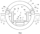
- FIG. 1 illustrates an example of a transportation machine incorporating a loop heat pipe 10 according to the exemplary embodiment of the present invention.
- the loop heat pipe 10 is suitable for incorporation into a transportation machine tiltable about a tilt axis C.
- Examples of the transportation machine include watercrafts (including submersibles), railcars, automobiles, and aircrafts.
- the following describes an aircraft 50 incorporating the loop heat pipe 10.
- FIG. 1 partially shows a fuselage 51 and main wings 53 of the aircraft 50.
- the fuselage 51 has a multilayer structure including an outer panel 52 and an inner wall 54 located closer to the cabin than the outer panel 52. Between the outer panel 52 and inner wall 54 are defined cooling chambers 55a and 55b.
- the first cooling chamber 55a is located on the right side of the fuselage 51 in the figure
- the second cooling chamber 55b is located on the left side of the fuselage 51 in the figure.
- the first and second cooling chambers 55a and 55b may be separate from or in communication with each other.
- the temperatures inside the cooling chambers 55a and 55b are low because of cold energy transferred from the outer panel 52 which during flight is exposed to outside air (an example of an external fluid) having a considerably lower temperature than that near the ground.
- the outer panel 52 may be provided with air inlets and outlets communicating with the cooling chambers 55a and 55b, and the outside air may be introduced into the cooling chambers 55 during flight.
- the left and right main wings 53 are joined to the lateral sides of the fuselage 51.
- Each main wing 53 has an interior enclosing a fuel tank 57.
- the main wing 53 is exposed to outside air having a considerably lower temperature than that near the ground, and the fuel tank 57 and the fuel stored in it are cooled by the outside air.
- the above aircraft 50 incorporates the loop heat pipe 10 to cool a heat-generating element 99 located in the fuselage 51.
- the heat-generating element 99 include, but are not limited to: an electronic device including heat-generating parts, such as a control board, an engine control unit (ECU), or a computer; a friction heat-generating mechanical part such as a bearing; and a battery. Air inside the cabin may be used as the heat source for the evaporator 2 instead of the heat-generating element 99.
- the loop heat pipe 10 includes a first loop 10a and a second loop 10b as circulation paths. These circulation paths are in communication at the evaporator 2.
- the first loop 10a is formed by the evaporator 2, a first vapor conduit 4a, a first condenser 3a, and a first liquid conduit 5a.
- the second loop 10b is formed by the evaporator 2, a second vapor conduit 4b, a second condenser 3b, and a second liquid conduit 5b.
- the first and second loops 10a and 10b share the evaporator 2.
- the loop heat pipe 10 is degassed beforehand to remove a non-condensable gas such as air and then charged with a working fluid.
- the working fluid is not limited to particular fluids, and may be a condensable fluid commonly used as a working fluid in heat pipes. Examples of the condensable fluid include water, an alcohol, ammonia, a fluorocarbon, a hydrofluorocarbon, a hydrofluoroether, and a liquid mixture of these fluids.
- the evaporator 2 includes a heat transfer plate 21 and a housing 22 defining a working fluid-receiving chamber 23.
- the heat transfer plate 21 is thermally connected to the heat-generating element 99, for example, via thermal grease or a heat transfer sheet.
- the working fluid in the working fluid-receiving chamber 23 absorbs heat from the heat-generating element 99 via the heat transfer plate 21, and a part of the working fluid boils and changes into the gas phase.
- the two-phase working fluid consisting of the vapor phase resulting from the boiling and the liquid phase moves in the first vapor conduit 4a connecting the outlet of the evaporator 2 and the inlet of the first condenser 3a under the action of pressure difference and buoyancy and reaches the first condenser 3a.
- the two-phase working fluid moves in the second vapor conduit 4b connecting the outlet of the evaporator 2 and the inlet of the second condenser 3b under the action of pressure difference and buoyancy and reaches the second condenser 3b. That is, the working fluid-receiving chamber 23 is in communication with both the first and second condensers 3a and 3b.
- the first condenser 3a is located in the first cooling chamber 55a, and the second condenser 3b is located in the second cooling chamber 55b.
- a fan 56 for forcing a gas flow to pass the condenser 3a or 3b.
- the first and second condensers 3a and 3b have substantially the same structure.
- Each of the first and second condensers 3a and 3b is provided with a cooling path (not shown), and the two-phase working fluid releases heat and is cooled into the liquid phase during passage through the cooling path.
- the liquid-phase working fluid descends in the first liquid conduit 5a connecting the outlet of the first condenser 3a and the inlet of the evaporator 2 under the action of gravity and returns to the evaporator 2.
- the working fluid changed into the liquid phase in the second condenser 3b descends in the second liquid conduit 5b connecting the outlet of the second condenser 3b and the inlet of the evaporator 2 under the action of gravity and returns to the evaporator 2.
- a position assumed by the loop heat pipe 10 when the aircraft 50 (an example of the transportation machine) incorporating the loop heat pipe 10 is placed on a horizontal surface is defined as a "reference position".
- the first and second condensers 3a and 3b are located above the evaporator 2.
- the working fluid naturally circulates in the first and second loops 10a and 10b under the action of head-related pressure difference.
- the head difference originating from the height difference between the location of the evaporator 2 and the locations of the condensers 3a and 3b changes, and accordingly the drive force for allowing the working fluid to circulate changes.
- the first and second condensers 3a and 3b are arranged such that in the loop heat pipe 10 assuming the reference position, the condensers 3a and 3b are spaced apart in the horizontal direction, with the tilt axis C of the aircraft 50 (i.e., the rotational center of tilting movement) and the evaporator 2 interposed between the condensers 3a and 3b. Additionally, in the loop heat pipe 10 assuming the reference position, the evaporator 2 is located in a vertical plane passing through the tilt axis C.
- the first and second condensers 3a and 3b as viewed in a direction parallel to the tilt axis C are located symmetrically about a vertical line passing through the tilt axis C.
- the head difference originating from the height difference between the locations of the first condenser 3a and evaporator 2 becomes greater than when the loop heat pipe 10 is in the reference position, and the drive force for allowing the working fluid to circulate in the first loop 10a remains the same or increases, although the head difference originating from the height difference between the locations of the second condenser 3b and evaporator 2 and therefore the drive force for allowing the working fluid to circulate in the second loop 10b become smaller than when the loop heat pipe 10 is in the reference position.
- the overall circulation flow rate of the working fluid remains unchanged, so that the heat transport rate can be kept high enough to cool the heat-generating element 99 sufficiently.
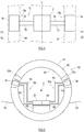
- FIG. 3 is a plan view illustrating the relationship between the location of the evaporator 2 and the locations of the two condensers 3a and 3b.
- the first and second condensers 3a and 3b are spaced apart in the direction of the tilt axis C, with the evaporator 2 interposed between the condensers 3a and 3b. That is, in the aircraft 50, the locations of the first and second condensers 3a and 3b in the front-rear direction are spaced apart, with the evaporator 2 interposed between the locations of the condensers 3a and 3b.
- the drive force for allowing the working fluid to circulate increases in one of the first and second loops 10a and 10b, although the drive force decreases in the other of the first and second loops 10a and 10b.
- the total amount of working fluid circulation of the first and second loops 10a and 10b is maintained at a sufficient level, and a significant decrease in the heat transport rate can be avoided.
- the locations of the evaporator 2 and the two condensers 3a and 3b in the direction of the tilt axis C may be the same as shown in FIG. 4 .
- the loop heat pipe 10 is incorporated into a transportation machine tiltable about a tilt axis C and includes: an evaporator 2 that changes at least a part of a working fluid from a liquid phase into a gas phase; a first condenser 3a that changes the working fluid from the gas phase into the liquid phase; a second condenser 3b that changes the working fluid from the gas phase into the liquid phase; a first vapor conduit 4a connecting the evaporator and the first condenser; a first liquid conduit 5a connecting the evaporator and the first condenser; a second vapor conduit 4b connecting the evaporator and the second condenser; and a second liquid conduit 5b connecting the evaporator and the second condenser.
- the first and second condensers 3a and 3b are located above the evaporator 2, and the first and second condensers 3a and 3b are spaced apart in a horizontal direction, with the tilt axis C and the evaporator 2 interposed between the first and second condensers 3a and 3b.
- the transportation machine includes a heat-generating element 99 and the loop heat pipe 10, and the evaporator 2 of the loop heat pipe 10 uses the heat-generating element 99 as a heat source to evaporate the working fluid.
- the transportation machine is an aircraft 50.
- the aircraft 50 includes an outer panel 52 exposed to an external fluid and an inner wall 54 located inward of the outer panel 52, and at least one of the first and second condensers 3a and 3b is located in a cooling chamber 55a or 55b defined between the outer panel 52 and the inner wall 54.
- the drive force for allowing the working fluid to flow from one of the first and second condensers 3a and 3b to the evaporator 2 is kept large enough, although the drive force for allowing the working fluid to flow from the other of the first and second condensers 3a and 3b to the evaporator 2 decreases.
- a sufficient amount of working fluid circulation is maintained, and the heat transport continues without a decrease in heat transport rate.
- the evaporator 2 may be located in a vertical plane passing through the tilt axis C when the transportation machine is placed on a horizontal surface.
- the evaporator 2 When, as in this case, the evaporator 2 is located on the tilt axis C, a good balance can be achieved between the flows of the working fluid from the evaporator 2 to the first and second condensers 3a and 3b and between the flows of the working fluid from the first and second condensers 3a and 3b to the evaporator 2.
- the first and second condensers 3a and 3b may be located symmetrically about a vertical line passing through the tilt axis C.
- the horizontal distance from the first condenser 3a to the tilt axis C and the horizontal distance from the second condenser 3b to the tilt axis C are equal, and a good balance can be achieved between the flows of the working fluid from the evaporator 2 to the first and second condensers 3a and 3b and between the flows of the working fluid from the first and second condensers 3a and 3b to the evaporator 2.
- the first and second condensers 3a and 3b may be spaced apart in a direction of the tilt axis C, with the evaporator 2 interposed between the first and second condensers 3a and 3b.
- the transportation machine may include an outer panel 52 exposed to an external fluid and an inner wall 54 located inward of the outer panel 52, and at least one of the first and second condensers 3a and 3b may be located in a cooling chamber 55a or 55b defined between the outer panel 52 and the inner wall. 54.
- the working fluid can be condensed using cold energy from the external fluid (outside air).
- the transportation machine when the transportation machine is for use in an environment where the temperature of the outside air is considerably lower than normal temperatures (such as when the transportation machine is the aircraft 50), a large temperature difference is created between the heat-generating element 99 to which the evaporator 2 is thermally connected and the medium to which the condensers 3a and 3b release heat and, in consequence, more efficient heat transport can be achieved.
- the transportation machine may further include a fuel tank 57, and at least one of the first and second condensers 3a and 3b may be located in a liquid phase contained in the fuel tank.
- the working fluid can be condensed using the fuel tank 57 having a high heat capacity.
- the fuel tank 57 is adapted to actively exchange heat with an external fluid having a low temperature, a large temperature difference is created between the heat-generating element 99 to which the evaporator 2 is thermally connected and the medium to which the condensers 3a and 3b release heat and, in consequence, more efficient heat transport can be achieved.
- the two condensers 3a and 3b are connected to the evaporator 2
- three or more condensers may be connected to the evaporator 2.
- the first and second loops 10a and 10b may have circulation paths independent of each other.
- the loop heat pipe 10 may be configured such that, as shown in FIG. 5 , the first loop 10a includes a first evaporator 2a and the second loop 10b includes a second evaporator 2b.
- the first and second evaporators 2a and 2b may be thermally connected to the heat-generating element 99 via a heat distribution plate 98 made of a material with high thermal conductivity.
- the loop heat pipe 10 of the above embodiment is not limited to the thermosyphon type, and may be of the wick type.
- the loop heat pipe of the wick type uses not only the capillary force acting on the working fluid in the wick but also gravity to return the working fluid from the condenser 3 to the evaporator 2.
- the present invention can offer the benefits as described above also when applied to a loop heat pipe of the wick type.
Landscapes
- Engineering & Computer Science (AREA)
- General Engineering & Computer Science (AREA)
- Mechanical Engineering (AREA)
- Combustion & Propulsion (AREA)
- Chemical & Material Sciences (AREA)
- Life Sciences & Earth Sciences (AREA)
- Sustainable Development (AREA)
- Physics & Mathematics (AREA)
- Thermal Sciences (AREA)
- Aviation & Aerospace Engineering (AREA)
- Health & Medical Sciences (AREA)
- Pulmonology (AREA)
- General Health & Medical Sciences (AREA)
- Cooling Or The Like Of Electrical Apparatus (AREA)
Abstract
Description
- The present invention relates to a loop heat pipe and a transportation machine including the loop heat pipe.
- A loop heat pipe technology has been traditionally known which uses phase changes of a working fluid to achieve high-density heat transport. A heat transport system employing such a loop heat pipe has been used, for example, to cool an electronic device such as a computer or home electric appliance. In some loop heat pipes, the working fluid is circulated by means of capillary force and/or gravity.
- A loop heat pipe includes a closed loop formed by an evaporator, a condenser, a vapor conduit leading from the evaporator to the condenser, and a liquid conduit leading from the condenser to the evaporator. The closed loop is charged with a working fluid. In the evaporator, the working fluid in a liquid phase is heated by heat transferred from a heat-generating element, and a part of the working fluid changes into a gas phase. The gas-liquid two-phase working fluid moves in the vapor conduit under the action of pressure difference and buoyancy and reaches the condenser. In the condenser, the working fluid is cooled into the liquid phase. The liquid-phase working fluid returns to the evaporator under the action of capillary force and/or gravity. In this manner, the loop heat pipe allows the working fluid to circulate in the two-phase closed loop and transport heat from the evaporator to the condenser, thereby cooling the heat-generating element thermally connected to the evaporator.
- When the loop heat pipe as described above is one which uses gravity for circulation of the working fluid, a change in the position of the loop heat pipe could reduce or reverse the head difference created by a height difference between the locations of the condenser and evaporator, thus making it harder for the working fluid to move from the condenser to the evaporator. In the event that the tilt of the loop heat pipe is further increased due to a change in position, the working fluid has difficulty in returning to the evaporator, and the heat transport could eventually cease. To address this problem,
Patent Literature 1 proposes a multi-loop heat pipe adapted for use in an electronic device such as a laptop computer or smartphone which is used in various positions including horizontal, vertical, and oblique positions, the multi-loop heat pipe being capable of exhibiting the heat transport function in any position. The multi-loop heat pipe includes a stack of two loop heat pipes independent of each other, and each loop heat pipe is in the form of a rectangle at diagonally opposite corners of which an evaporator and a condenser are located respectively. In plan view, the evaporators of the two loop heat pipes overlap each other, while the condensers are at different locations. - PTL 1:
Japanese Laid-Open Patent Application Publication No. 2012-233642 - Electronic devices have become more and more sophisticated and miniaturized, and this has recently led to a growing demand for thermal management in transportation machines such as watercrafts, railcars, automobiles, and aircrafts which are equipped with a large number of the sophisticated, miniaturized devices. Some transportation machines incorporate a heat transport system including a loop heat pipe as described above which uses gravity for circulation of a working fluid, and such a transportation machine, the position of the body of which constantly changes, suffers a position change-induced decrease in the drive force for allowing the working fluid to circulate and a corresponding decrease in the heat transport rate.
- In the multi-loop heat pipe of
Patent Literature 1, one of the two independent loop heat pipes maintains the circulation of the working fluid in the event of a change in the position of the multi-loop heat pipe, and the position change-induced cessation of heat transport can be prevented. In this case, however, the heat transport in the other loop heat pipe ceases. Thus, the size of the cooling device needs to be increased in order to ensure an adequate heat transport rate when the cooling device is tilted owing to a position change. - The present invention has been made in view of the above circumstances, and an object of the present invention is to provide a loop heat pipe and a transportation machine including the loop heat pipe, the loop heat pipe and transportation machine having a reduced size and being adapted to maintain a sufficient heat transport rate and reliably cool a cooling target despite changes in the position of the loop heat pipe.
- A loop heat pipe according to an aspect of the present invention is incorporated into a transportation machine tiltable about a tilt axis and includes: an evaporator that changes at least a part of a working fluid from a liquid phase into a gas phase; a first condenser that changes the working fluid from the gas phase into the liquid phase; a second condenser that changes the working fluid from the gas phase into the liquid phase; a first vapor conduit connecting the evaporator and the first condenser; a first liquid conduit connecting the evaporator and the first condenser; a second vapor conduit connecting the evaporator and the second condenser; and a second liquid conduit connecting the evaporator and the second condenser. When the transportation machine is placed on a horizontal surface, the first and second condensers are located above the evaporator, and the first and second condensers are spaced apart in a horizontal direction, with the tilt axis and the evaporator interposed between the first and second condensers.
- With the above loop heat pipe, when the transportation machine rotates about the tilt axis and accordingly the position of the loop heat pipe is changed, the drive force for allowing the working fluid to flow from one of the first and second condensers to the evaporator increases, although the drive force for allowing the working fluid to flow from the other of the first and second condensers to the evaporator decreases. As such, the loop heat pipe can, despite changes in its position, maintain a sufficient amount of working fluid circulation and continue heat transport without a decrease in heat transport rate.
- A transportation machine according to an aspect of the present invention includes a heat-generating element and the loop heat pipe as defined above, and the evaporator of the loop heat pipe uses the heat-generating element as a heat source to evaporate the working fluid.
- As previously stated, the loop heat pipe can maintain sufficient heat transport performance despite changes in its position. Thus, such a loop heat pipe is suitable for cooling a heat-generating element mounted on a transportation machine the positon of the body of which constantly changes.
- The present invention can provide a loop heat pipe and a transportation machine including the loop heat pipe, the loop heat pipe and transportation machine being adapted to maintain a sufficient heat transport rate despite changes in the position of the loop heat pipe.
-
-
FIG. 1 illustrates a transportation machine incorporating a loop heat pipe according to an exemplary embodiment of the present invention. -
FIG. 2 illustrates the transportation machine ofFIG. 1 tilting about a tilt axis. -
FIG. 3 is a plan view illustrating the relationship between the location of an evaporator and the locations of two condensers. -
FIG. 4 is a plan view illustrating a variant of the relationship between the location of the evaporator and the locations of the two condensers. -
FIG. 5 illustrates the configuration of a loop heat pipe according to a first variant. - Hereinafter, an exemplary embodiment of the present invention will be described with reference to the drawings.
FIG. 1 illustrates an example of a transportation machine incorporating aloop heat pipe 10 according to the exemplary embodiment of the present invention. Theloop heat pipe 10 is suitable for incorporation into a transportation machine tiltable about a tilt axis C. Examples of the transportation machine include watercrafts (including submersibles), railcars, automobiles, and aircrafts. The following describes anaircraft 50 incorporating theloop heat pipe 10. -
FIG. 1 partially shows afuselage 51 andmain wings 53 of theaircraft 50. Thefuselage 51 has a multilayer structure including anouter panel 52 and aninner wall 54 located closer to the cabin than theouter panel 52. Between theouter panel 52 andinner wall 54 are definedcooling chambers first cooling chamber 55a is located on the right side of thefuselage 51 in the figure, and thesecond cooling chamber 55b is located on the left side of thefuselage 51 in the figure. The first andsecond cooling chambers cooling chambers outer panel 52 which during flight is exposed to outside air (an example of an external fluid) having a considerably lower temperature than that near the ground. Alternatively, theouter panel 52 may be provided with air inlets and outlets communicating with thecooling chambers cooling chambers 55 during flight. - The left and right
main wings 53 are joined to the lateral sides of thefuselage 51. Eachmain wing 53 has an interior enclosing afuel tank 57. During flight, themain wing 53 is exposed to outside air having a considerably lower temperature than that near the ground, and thefuel tank 57 and the fuel stored in it are cooled by the outside air. - The
above aircraft 50 incorporates theloop heat pipe 10 to cool a heat-generatingelement 99 located in thefuselage 51. Examples of the heat-generatingelement 99 include, but are not limited to: an electronic device including heat-generating parts, such as a control board, an engine control unit (ECU), or a computer; a friction heat-generating mechanical part such as a bearing; and a battery. Air inside the cabin may be used as the heat source for theevaporator 2 instead of the heat-generatingelement 99. - The
loop heat pipe 10 includes afirst loop 10a and asecond loop 10b as circulation paths. These circulation paths are in communication at theevaporator 2. Thefirst loop 10a is formed by theevaporator 2, afirst vapor conduit 4a, afirst condenser 3a, and a firstliquid conduit 5a. Thesecond loop 10b is formed by theevaporator 2, asecond vapor conduit 4b, asecond condenser 3b, and a secondliquid conduit 5b. The first andsecond loops evaporator 2. - The
loop heat pipe 10 is degassed beforehand to remove a non-condensable gas such as air and then charged with a working fluid. The working fluid is not limited to particular fluids, and may be a condensable fluid commonly used as a working fluid in heat pipes. Examples of the condensable fluid include water, an alcohol, ammonia, a fluorocarbon, a hydrofluorocarbon, a hydrofluoroether, and a liquid mixture of these fluids. - The
evaporator 2 includes aheat transfer plate 21 and ahousing 22 defining a working fluid-receivingchamber 23. Theheat transfer plate 21 is thermally connected to the heat-generatingelement 99, for example, via thermal grease or a heat transfer sheet. In thisevaporator 2, the working fluid in the working fluid-receivingchamber 23 absorbs heat from the heat-generatingelement 99 via theheat transfer plate 21, and a part of the working fluid boils and changes into the gas phase. The two-phase working fluid consisting of the vapor phase resulting from the boiling and the liquid phase moves in thefirst vapor conduit 4a connecting the outlet of theevaporator 2 and the inlet of thefirst condenser 3a under the action of pressure difference and buoyancy and reaches thefirst condenser 3a. Further, the two-phase working fluid moves in thesecond vapor conduit 4b connecting the outlet of theevaporator 2 and the inlet of thesecond condenser 3b under the action of pressure difference and buoyancy and reaches thesecond condenser 3b. That is, the working fluid-receivingchamber 23 is in communication with both the first andsecond condensers - The
first condenser 3a is located in thefirst cooling chamber 55a, and thesecond condenser 3b is located in thesecond cooling chamber 55b. In each of thecooling chambers fan 56 for forcing a gas flow to pass thecondenser second condensers second condensers liquid conduit 5a connecting the outlet of thefirst condenser 3a and the inlet of theevaporator 2 under the action of gravity and returns to theevaporator 2. Likewise, the working fluid changed into the liquid phase in thesecond condenser 3b descends in the secondliquid conduit 5b connecting the outlet of thesecond condenser 3b and the inlet of theevaporator 2 under the action of gravity and returns to theevaporator 2. - For the
loop heat pipe 10 configured as described above, a position assumed by theloop heat pipe 10 when the aircraft 50 (an example of the transportation machine) incorporating theloop heat pipe 10 is placed on a horizontal surface is defined as a "reference position". In theloop heat pipe 10 assuming the reference position, the first andsecond condensers evaporator 2. The working fluid naturally circulates in the first andsecond loops loop heat pipe 10 is changed from the reference position, the head difference originating from the height difference between the location of theevaporator 2 and the locations of thecondensers - To accommodate these changes, the first and
second condensers loop heat pipe 10 assuming the reference position, thecondensers evaporator 2 interposed between thecondensers loop heat pipe 10 assuming the reference position, theevaporator 2 is located in a vertical plane passing through the tilt axis C. Further, in theloop heat pipe 10 assuming the reference position, the first andsecond condensers evaporator 2 andcondensers aircraft 50 rotates about the tilt axis C as shown inFIG. 2 , the head difference originating from the height difference between the locations of thefirst condenser 3a andevaporator 2 becomes greater than when theloop heat pipe 10 is in the reference position, and the drive force for allowing the working fluid to circulate in thefirst loop 10a remains the same or increases, although the head difference originating from the height difference between the locations of thesecond condenser 3b andevaporator 2 and therefore the drive force for allowing the working fluid to circulate in thesecond loop 10b become smaller than when theloop heat pipe 10 is in the reference position. As such, in the event that the position of theloop heat pipe 10 is changed in response to a tilting movement of theaircraft 50, the overall circulation flow rate of the working fluid remains unchanged, so that the heat transport rate can be kept high enough to cool the heat-generatingelement 99 sufficiently. -
FIG. 3 is a plan view illustrating the relationship between the location of theevaporator 2 and the locations of the twocondensers FIG. 3 , the first andsecond condensers evaporator 2 interposed between thecondensers aircraft 50, the locations of the first andsecond condensers evaporator 2 interposed between the locations of thecondensers aircraft 50 tilts in the front-rear direction during ascent or descent of theaircraft 50, the drive force for allowing the working fluid to circulate increases in one of the first andsecond loops second loops second loops evaporator 2 and the locations of the first andsecond condensers aircraft 50 tilts in the front-rear direction, the locations of theevaporator 2 and the twocondensers FIG. 4 . - As described above, the
loop heat pipe 10 according to the exemplary embodiment is incorporated into a transportation machine tiltable about a tilt axis C and includes: anevaporator 2 that changes at least a part of a working fluid from a liquid phase into a gas phase; afirst condenser 3a that changes the working fluid from the gas phase into the liquid phase; asecond condenser 3b that changes the working fluid from the gas phase into the liquid phase; afirst vapor conduit 4a connecting the evaporator and the first condenser; a firstliquid conduit 5a connecting the evaporator and the first condenser; asecond vapor conduit 4b connecting the evaporator and the second condenser; and a secondliquid conduit 5b connecting the evaporator and the second condenser. When the transportation machine is placed on a horizontal surface, the first andsecond condensers evaporator 2, and the first andsecond condensers evaporator 2 interposed between the first andsecond condensers - The transportation machine according to the exemplary embodiment includes a heat-generating
element 99 and theloop heat pipe 10, and theevaporator 2 of theloop heat pipe 10 uses the heat-generatingelement 99 as a heat source to evaporate the working fluid. In the exemplary embodiment, the transportation machine is anaircraft 50. Theaircraft 50 includes anouter panel 52 exposed to an external fluid and aninner wall 54 located inward of theouter panel 52, and at least one of the first andsecond condensers cooling chamber outer panel 52 and theinner wall 54. - With the
loop heat pipe 10 and the transportation machine including theloop heat pipe 10, when the position of theloop heat pipe 10 is changed in response to a tilting movement of the transportation machine, the drive force for allowing the working fluid to flow from one of the first andsecond condensers evaporator 2 is kept large enough, although the drive force for allowing the working fluid to flow from the other of the first andsecond condensers evaporator 2 decreases. As such, despite the change in the position of theloop heat pipe 10, a sufficient amount of working fluid circulation is maintained, and the heat transport continues without a decrease in heat transport rate. - In the
loop heat pipe 10 and the transportation machine incorporating theloop heat pipe 10, as illustrated in the exemplary embodiment, theevaporator 2 may be located in a vertical plane passing through the tilt axis C when the transportation machine is placed on a horizontal surface. - When, as in this case, the
evaporator 2 is located on the tilt axis C, a good balance can be achieved between the flows of the working fluid from theevaporator 2 to the first andsecond condensers second condensers evaporator 2. - In the loop heat pipe and the transportation machine, the first and
second condensers - In this case, the horizontal distance from the
first condenser 3a to the tilt axis C and the horizontal distance from thesecond condenser 3b to the tilt axis C are equal, and a good balance can be achieved between the flows of the working fluid from theevaporator 2 to the first andsecond condensers second condensers evaporator 2. - In the
loop heat pipe 10 and the transportation machine incorporating theloop heat pipe 10, as illustrated in the exemplary embodiment, the first andsecond condensers evaporator 2 interposed between the first andsecond condensers - In this case, when the transportation machine rotates about an axis orthogonal to the tilt axis C and accordingly the position of the
loop heat pipe 10 changes, the drive force for allowing the working fluid to flow from one of the first andsecond condensers evaporator 2 is kept large enough, although the drive force for allowing the working fluid to flow from the other of the first andsecond condensers evaporator 2 decreases. As such, despite the change in the position of theloop heat pipe 10, a sufficient amount of working fluid circulation is maintained, and the heat transport continues. - The transportation machine may include an
outer panel 52 exposed to an external fluid and aninner wall 54 located inward of theouter panel 52, and at least one of the first andsecond condensers cooling chamber outer panel 52 and the inner wall. 54. - In such a transportation machine, the working fluid can be condensed using cold energy from the external fluid (outside air). In particular, when the transportation machine is for use in an environment where the temperature of the outside air is considerably lower than normal temperatures (such as when the transportation machine is the aircraft 50), a large temperature difference is created between the heat-generating
element 99 to which theevaporator 2 is thermally connected and the medium to which thecondensers - The transportation machine may further include a
fuel tank 57, and at least one of the first andsecond condensers - In such a transportation machine, the working fluid can be condensed using the
fuel tank 57 having a high heat capacity. In particular, when thefuel tank 57 is adapted to actively exchange heat with an external fluid having a low temperature, a large temperature difference is created between the heat-generatingelement 99 to which theevaporator 2 is thermally connected and the medium to which thecondensers - Although the foregoing has described a preferred embodiment of the present invention, the scope of the present invention embraces modifications made to the details of the structure and/or function of the above embodiment without departing from the concept of the present invention. For example, the configurations of the
loop heat pipe 10 and transportation machine can be modified as described below. - For example, while in the
loop heat pipe 10 of the above embodiment the twocondensers evaporator 2, three or more condensers may be connected to theevaporator 2. - For example, while in the
loop heat pipe 10 of the above embodiment the first andsecond loops evaporator 2, the first andsecond loops loop heat pipe 10 may be configured such that, as shown inFIG. 5 , thefirst loop 10a includes afirst evaporator 2a and thesecond loop 10b includes asecond evaporator 2b. To cool the heat-generatingelement 99 uniformly, the first andsecond evaporators element 99 via aheat distribution plate 98 made of a material with high thermal conductivity. - For example, the
loop heat pipe 10 of the above embodiment is not limited to the thermosyphon type, and may be of the wick type. The loop heat pipe of the wick type uses not only the capillary force acting on the working fluid in the wick but also gravity to return the working fluid from the condenser 3 to theevaporator 2. Thus, the present invention can offer the benefits as described above also when applied to a loop heat pipe of the wick type. -
- 2: evaporator
- 3a, 3b: condenser
- 4a, 4b: vapor conduit
- 5a, 5b: liquid conduit
- 10: loop heat pipe
- 21: heat transfer plate
- 22: housing
- 23: working fluid-receiving chamber
- 50: aircraft (example of transportation machine)
- 51: fuselage
- 52: outer panel
- 53: main wing
- 54: inner wall
- 55: cooling chamber
- 56: fan
- 57: fuel tank
- 99: heat-generating element
Claims (7)
- A loop heat pipe incorporated into a transportation machine tiltable about a tilt axis, comprising:an evaporator that changes at least a part of a working fluid from a liquid phase into a gas phase;a first condenser that changes the working fluid from the gas phase into the liquid phase;a second condenser that changes the working fluid from the gas phase into the liquid phase;a first vapor conduit connecting the evaporator and the first condenser;a first liquid conduit connecting the evaporator and the first condenser;a second vapor conduit connecting the evaporator and the second condenser; anda second liquid conduit connecting the evaporator and the second condenser, whereinwhen the transportation machine is placed on a horizontal surface,the first and second condensers are located above the evaporator, andthe first and second condensers are spaced apart in a horizontal direction, with the tilt axis and the evaporator interposed between the first and second condensers.
- The loop heat pipe according to claim 1, wherein the evaporator is located in a vertical plane passing through the tilt axis when the transportation machine is placed on a horizontal surface.
- The loop heat pipe according to claim 2, wherein the first and second condensers, as viewed in a direction parallel to the tilt axis, are located symmetrically about a vertical line passing through the tilt axis.
- The loop heat pipe according to any one of claims 1 to 3, wherein the first and second condensers are spaced apart in a direction of the tilt axis, with the evaporator interposed between the first and second condensers.
- A transportation machine comprising:a heat-generating element; andthe loop heat pipe according to any one of claims 1 to 4, whereinthe evaporator of the loop heat pipe uses the heat-generating element as a heat source to evaporate the working fluid.
- The transportation machine according to claim 5, further comprising:an outer panel exposed to an external fluid; andan inner wall located inward of the outer panel, whereinat least one of the first and second condensers is located in a cooling chamber defined between the outer panel and the inner wall.
- The transportation machine according to claim 5, further comprising a fuel tank, wherein
at least one of the first and second condensers is located in a liquid phase contained in the fuel tank.
Applications Claiming Priority (2)
| Application Number | Priority Date | Filing Date | Title |
|---|---|---|---|
| JP2018245272A JP2020106207A (en) | 2018-12-27 | 2018-12-27 | Loop-type heat pipe and transporter |
| PCT/JP2019/050597 WO2020138079A1 (en) | 2018-12-27 | 2019-12-24 | Loop-type heat pipe and transport device |
Publications (2)
| Publication Number | Publication Date |
|---|---|
| EP3904812A1 true EP3904812A1 (en) | 2021-11-03 |
| EP3904812A4 EP3904812A4 (en) | 2022-09-14 |
Family
ID=71127202
Family Applications (1)
| Application Number | Title | Priority Date | Filing Date |
|---|---|---|---|
| EP19902970.3A Withdrawn EP3904812A4 (en) | 2018-12-27 | 2019-12-24 | LOOPED HEAT PIPE AND TRANSPORT DEVICE |
Country Status (4)
| Country | Link |
|---|---|
| US (1) | US20220065548A1 (en) |
| EP (1) | EP3904812A4 (en) |
| JP (1) | JP2020106207A (en) |
| WO (1) | WO2020138079A1 (en) |
Families Citing this family (2)
| Publication number | Priority date | Publication date | Assignee | Title |
|---|---|---|---|---|
| GB201813420D0 (en) * | 2018-08-17 | 2018-10-03 | Leonardo Mw Ltd | A gas-liquid separator |
| US12098673B2 (en) * | 2022-07-13 | 2024-09-24 | Brian Lee Moffat | Rotary closed-cycle externally-heated engine |
Family Cites Families (17)
| Publication number | Priority date | Publication date | Assignee | Title |
|---|---|---|---|---|
| US4254821A (en) * | 1979-08-10 | 1981-03-10 | Thermo Electron Corporation | Heat pipe deicing apparatus |
| US5423498A (en) * | 1993-04-27 | 1995-06-13 | E-Systems, Inc. | Modular liquid skin heat exchanger |
| TW331586B (en) * | 1997-08-22 | 1998-05-11 | Biing-Jiun Hwang | Network-type heat pipe device |
| JP2001165585A (en) * | 1999-12-06 | 2001-06-22 | Furukawa Electric Co Ltd:The | Flat heat pipe |
| JP3908060B2 (en) * | 2002-02-28 | 2007-04-25 | 三菱電機株式会社 | Mobile mounted antenna |
| JP2003298270A (en) * | 2002-03-29 | 2003-10-17 | Mitsubishi Electric Corp | Antenna device |
| GB2389174B (en) * | 2002-05-01 | 2005-10-26 | Rolls Royce Plc | Cooling systems |
| JP3785382B2 (en) * | 2002-07-12 | 2006-06-14 | 三菱電機株式会社 | Cooling device for mobile antenna |
| DE10361653B4 (en) * | 2003-12-30 | 2008-08-07 | Airbus Deutschland Gmbh | Cooling device for removing heat from an arranged in the interior of an aircraft heat source |
| JP2008527285A (en) * | 2005-01-03 | 2008-07-24 | ノイズ リミット エーピーエス | Multi-directional cooling system with bubble pump |
| DE102007060428B3 (en) * | 2007-12-14 | 2009-05-07 | Airbus Deutschland Gmbh | Fuel cell system i.e. evaporation-cooled fuel cell system, for use in aircraft, has control unit controlling temperature of cell, where cooling agent is transferred into gaseous state in aggregate condition |
| CN101566442A (en) * | 2009-05-31 | 2009-10-28 | 北京奇宏科技研发中心有限公司 | Serial-parallel type multi-evaporator loop heat pipe |
| JP5765047B2 (en) | 2011-05-02 | 2015-08-19 | 富士通株式会社 | Multi-loop heat pipe and electronic device |
| CN103000595B (en) * | 2011-09-08 | 2015-11-04 | 北京芯铠电子散热技术有限责任公司 | A kind of multidirectional turnover phase change heat-transfer device and preparation method thereof |
| ITTO20111025A1 (en) * | 2011-11-08 | 2013-05-09 | Alenia Aeronautica Spa | FUEL TANK FOR AIRCRAFT INCLUDED WITH FUEL HEATING SYSTEM AND FUEL HEATING SYSTEM FOR AIRCRAFT PROVIDED WITH SUCH A TANK |
| US20150068703A1 (en) * | 2013-09-06 | 2015-03-12 | Ge Aviation Systems Llc | Thermal management system and method of assembling the same |
| FR3039512B1 (en) * | 2015-07-28 | 2017-12-22 | Thales Sa | HEATING A FIRST AERONAUTICAL AIRCRAFT EQUIPMENT |
-
2018
- 2018-12-27 JP JP2018245272A patent/JP2020106207A/en active Pending
-
2019
- 2019-12-24 US US17/418,253 patent/US20220065548A1/en not_active Abandoned
- 2019-12-24 WO PCT/JP2019/050597 patent/WO2020138079A1/en not_active Ceased
- 2019-12-24 EP EP19902970.3A patent/EP3904812A4/en not_active Withdrawn
Also Published As
| Publication number | Publication date |
|---|---|
| US20220065548A1 (en) | 2022-03-03 |
| WO2020138079A1 (en) | 2020-07-02 |
| JP2020106207A (en) | 2020-07-09 |
| EP3904812A4 (en) | 2022-09-14 |
Similar Documents
| Publication | Publication Date | Title |
|---|---|---|
| EP3723461B1 (en) | Cooling system and method for cooling an electronics cabinet | |
| CN109690223B (en) | Equipment temperature regulator | |
| US20110170263A1 (en) | Aircraft Electronics Cooling Apparatus For An Aircraft Having A Liquid Cooling System | |
| EP3905320B1 (en) | Evaporator and loop heat pipe | |
| US20220034596A1 (en) | Evaporator and loop heat pipe | |
| CN109795281B (en) | Multifunctional reservoir for a secondary circuit climate control system and secondary circuit climate control system including the multifunctional reservoir | |
| JP6601567B2 (en) | Equipment temperature controller | |
| US20240291070A1 (en) | Thermal regulation device for at least one electrical and/or electronic element | |
| US20220065548A1 (en) | Loop heat pipe and transportation machine | |
| CN110892225A (en) | Equipment temperature regulator | |
| US12568605B2 (en) | Loop heat pipe for low voltage drives | |
| JP5786132B2 (en) | Electric car | |
| JP2019040730A (en) | Battery temperature adjustment device | |
| EP3904811B1 (en) | Heat conveyance system and conveyance machinery | |
| EP4174937B1 (en) | Evaporator and loop heat pipe | |
| WO2026081581A1 (en) | Thermal management system, heating and cooling box device, and vehicle | |
| EP3904813A1 (en) | Loop-type heat pipe and transporter | |
| JP2024079261A (en) | Structure | |
| JP2018105525A (en) | Cooling device, electronic apparatus mounted with the same and electric vehicle | |
| KR102552549B1 (en) | Cooling device | |
| EP4613524B1 (en) | Thermal management device and method for adapting a temperature of an energy storage unit of a vehicle | |
| JP2017041577A (en) | Cooler and cooling method | |
| EP3904814A1 (en) | Evaporator and loop-type heat pipe | |
| KR102574636B1 (en) | Cooling device | |
| WO2019107058A1 (en) | Thermosiphon type heating system |
Legal Events
| Date | Code | Title | Description |
|---|---|---|---|
| STAA | Information on the status of an ep patent application or granted ep patent |
Free format text: STATUS: THE INTERNATIONAL PUBLICATION HAS BEEN MADE |
|
| PUAI | Public reference made under article 153(3) epc to a published international application that has entered the european phase |
Free format text: ORIGINAL CODE: 0009012 |
|
| STAA | Information on the status of an ep patent application or granted ep patent |
Free format text: STATUS: REQUEST FOR EXAMINATION WAS MADE |
|
| 17P | Request for examination filed |
Effective date: 20210721 |
|
| AK | Designated contracting states |
Kind code of ref document: A1 Designated state(s): AL AT BE BG CH CY CZ DE DK EE ES FI FR GB GR HR HU IE IS IT LI LT LU LV MC MK MT NL NO PL PT RO RS SE SI SK SM TR |
|
| DAV | Request for validation of the european patent (deleted) | ||
| DAX | Request for extension of the european patent (deleted) | ||
| A4 | Supplementary search report drawn up and despatched |
Effective date: 20220812 |
|
| RIC1 | Information provided on ipc code assigned before grant |
Ipc: F28D 15/02 20060101AFI20220808BHEP |
|
| STAA | Information on the status of an ep patent application or granted ep patent |
Free format text: STATUS: THE APPLICATION HAS BEEN WITHDRAWN |
|
| 18W | Application withdrawn |
Effective date: 20240802 |