EP3904693B1 - Kreiselverdichter und klimaanlage - Google Patents
Kreiselverdichter und klimaanlage Download PDFInfo
- Publication number
- EP3904693B1 EP3904693B1 EP19904130.2A EP19904130A EP3904693B1 EP 3904693 B1 EP3904693 B1 EP 3904693B1 EP 19904130 A EP19904130 A EP 19904130A EP 3904693 B1 EP3904693 B1 EP 3904693B1
- Authority
- EP
- European Patent Office
- Prior art keywords
- bearing
- thrust
- diffuser
- radial
- centrifugal compressor
- Prior art date
- Legal status (The legal status is an assumption and is not a legal conclusion. Google has not performed a legal analysis and makes no representation as to the accuracy of the status listed.)
- Active
Links
Images


Classifications
-
- F—MECHANICAL ENGINEERING; LIGHTING; HEATING; WEAPONS; BLASTING
- F04—POSITIVE - DISPLACEMENT MACHINES FOR LIQUIDS; PUMPS FOR LIQUIDS OR ELASTIC FLUIDS
- F04D—NON-POSITIVE-DISPLACEMENT PUMPS
- F04D17/00—Radial-flow pumps, e.g. centrifugal pumps; Helico-centrifugal pumps
- F04D17/08—Centrifugal pumps
- F04D17/10—Centrifugal pumps for compressing or evacuating
- F04D17/12—Multi-stage pumps
-
- F—MECHANICAL ENGINEERING; LIGHTING; HEATING; WEAPONS; BLASTING
- F04—POSITIVE - DISPLACEMENT MACHINES FOR LIQUIDS; PUMPS FOR LIQUIDS OR ELASTIC FLUIDS
- F04D—NON-POSITIVE-DISPLACEMENT PUMPS
- F04D17/00—Radial-flow pumps, e.g. centrifugal pumps; Helico-centrifugal pumps
- F04D17/08—Centrifugal pumps
- F04D17/10—Centrifugal pumps for compressing or evacuating
-
- F—MECHANICAL ENGINEERING; LIGHTING; HEATING; WEAPONS; BLASTING
- F04—POSITIVE - DISPLACEMENT MACHINES FOR LIQUIDS; PUMPS FOR LIQUIDS OR ELASTIC FLUIDS
- F04D—NON-POSITIVE-DISPLACEMENT PUMPS
- F04D29/00—Details, component parts, or accessories
- F04D29/05—Shafts or bearings, or assemblies thereof, specially adapted for elastic fluid pumps
- F04D29/051—Axial thrust balancing
-
- F—MECHANICAL ENGINEERING; LIGHTING; HEATING; WEAPONS; BLASTING
- F04—POSITIVE - DISPLACEMENT MACHINES FOR LIQUIDS; PUMPS FOR LIQUIDS OR ELASTIC FLUIDS
- F04D—NON-POSITIVE-DISPLACEMENT PUMPS
- F04D29/00—Details, component parts, or accessories
- F04D29/05—Shafts or bearings, or assemblies thereof, specially adapted for elastic fluid pumps
- F04D29/051—Axial thrust balancing
- F04D29/0513—Axial thrust balancing hydrostatic; hydrodynamic thrust bearings
-
- F—MECHANICAL ENGINEERING; LIGHTING; HEATING; WEAPONS; BLASTING
- F04—POSITIVE - DISPLACEMENT MACHINES FOR LIQUIDS; PUMPS FOR LIQUIDS OR ELASTIC FLUIDS
- F04D—NON-POSITIVE-DISPLACEMENT PUMPS
- F04D29/00—Details, component parts, or accessories
- F04D29/05—Shafts or bearings, or assemblies thereof, specially adapted for elastic fluid pumps
- F04D29/053—Shafts
-
- F—MECHANICAL ENGINEERING; LIGHTING; HEATING; WEAPONS; BLASTING
- F04—POSITIVE - DISPLACEMENT MACHINES FOR LIQUIDS; PUMPS FOR LIQUIDS OR ELASTIC FLUIDS
- F04D—NON-POSITIVE-DISPLACEMENT PUMPS
- F04D29/00—Details, component parts, or accessories
- F04D29/05—Shafts or bearings, or assemblies thereof, specially adapted for elastic fluid pumps
- F04D29/056—Bearings
- F04D29/057—Bearings hydrostatic; hydrodynamic
-
- F—MECHANICAL ENGINEERING; LIGHTING; HEATING; WEAPONS; BLASTING
- F04—POSITIVE - DISPLACEMENT MACHINES FOR LIQUIDS; PUMPS FOR LIQUIDS OR ELASTIC FLUIDS
- F04D—NON-POSITIVE-DISPLACEMENT PUMPS
- F04D29/00—Details, component parts, or accessories
- F04D29/08—Sealings
- F04D29/083—Sealings especially adapted for elastic fluid pumps
-
- F—MECHANICAL ENGINEERING; LIGHTING; HEATING; WEAPONS; BLASTING
- F04—POSITIVE - DISPLACEMENT MACHINES FOR LIQUIDS; PUMPS FOR LIQUIDS OR ELASTIC FLUIDS
- F04D—NON-POSITIVE-DISPLACEMENT PUMPS
- F04D29/00—Details, component parts, or accessories
- F04D29/08—Sealings
- F04D29/16—Sealings between pressure and suction sides
- F04D29/161—Sealings between pressure and suction sides especially adapted for elastic fluid pumps
- F04D29/162—Sealings between pressure and suction sides especially adapted for elastic fluid pumps of a centrifugal flow wheel
-
- F—MECHANICAL ENGINEERING; LIGHTING; HEATING; WEAPONS; BLASTING
- F04—POSITIVE - DISPLACEMENT MACHINES FOR LIQUIDS; PUMPS FOR LIQUIDS OR ELASTIC FLUIDS
- F04D—NON-POSITIVE-DISPLACEMENT PUMPS
- F04D29/00—Details, component parts, or accessories
- F04D29/26—Rotors specially for elastic fluids
- F04D29/266—Rotors specially for elastic fluids mounting compressor rotors on shafts
-
- F—MECHANICAL ENGINEERING; LIGHTING; HEATING; WEAPONS; BLASTING
- F04—POSITIVE - DISPLACEMENT MACHINES FOR LIQUIDS; PUMPS FOR LIQUIDS OR ELASTIC FLUIDS
- F04D—NON-POSITIVE-DISPLACEMENT PUMPS
- F04D29/00—Details, component parts, or accessories
- F04D29/40—Casings; Connections of working fluid
- F04D29/42—Casings; Connections of working fluid for radial or helico-centrifugal pumps
- F04D29/44—Fluid-guiding means, e.g. diffusers
- F04D29/441—Fluid-guiding means, e.g. diffusers especially adapted for elastic fluid pumps
-
- F—MECHANICAL ENGINEERING; LIGHTING; HEATING; WEAPONS; BLASTING
- F04—POSITIVE - DISPLACEMENT MACHINES FOR LIQUIDS; PUMPS FOR LIQUIDS OR ELASTIC FLUIDS
- F04D—NON-POSITIVE-DISPLACEMENT PUMPS
- F04D29/00—Details, component parts, or accessories
- F04D29/60—Mounting; Assembling; Disassembling
- F04D29/62—Mounting; Assembling; Disassembling of radial or helico-centrifugal pumps
- F04D29/624—Mounting; Assembling; Disassembling of radial or helico-centrifugal pumps especially adapted for elastic fluid pumps
Definitions
- the present disclosure relates to the technical field of air compression equipment, and in particular, to a centrifugal compressor and air conditioning equipment.
- a dynamic pressure gas bearing has the advantages of high precision, low friction loss, long life, low vibration, no pollution and no need of providing a lubricating medium, etc. Meanwhile, the dynamic pressure gas bearing is suitable for occasions with high rotating speed and high precision, and has a wide application prospect in centrifugal compressors, especially small centrifugal compressors.
- the clearance of the gas bearing is very small, only several microns or even tens of microns, and the machining precision of parts is required to be sub-micron. Therefore, it is very important to ensure a thrust surface clearance of the thrust bearing. If the clearance is controlled inaccurately, the performance of the thrust bearing will be reduced, and in severe cases, the bearing will fail.
- Patent US20030059315A1 discloses a turbo compressor, a radial bearing is inserted between the first support member and the outer circumferential face of the rotational shaft and between the second support member and the outer circumferential face of the rotational shaft, to support a load working in a radial direction of the rotational shaft.
- the thrust bearing is installed between the first cover member and the first support member, and a bearing chamber is formed where the bearing bush is rotatably positioned.
- DE102015007379A1 discloses a turbo compressor for a fuel cell.
- One aspect of embodiments of the present disclosure provides a centrifugal compressor according to claim 1.
- the fixing plate and the bearing support form an integrated structure.
- the fixing plate is configured to limit a displacement of the radial bearing towards one side of a diffuser along an axial direction.
- a locating ring is arranged at one end, facing towards a bearing support, of the fixing plate; the bearing support is provided with a second annular groove; the locating ring is arranged into the second groove; and an inner wall of the locating ring engages with an outer wall of a partial length section of a radial bearing.
- a first end of the bearing support abuts against diffuser
- a second end of the bearing support is connected to the shell and is configured to support a main shaft through the radial bearing, and radial outline dimensions of the bearing support gradually increase from the first end to the second end thereof.
- the bearing support is provided with a vent hole configured to communicate a space where the radial bearing is located with a space where the first thrust bearing and the second thrust bearing are located.
- the first thrust bearing is directly fixed at the bottom of the first groove.
- the centrifugal compressor further includes an impeller and a locking part, wherein the main shaft is internally provided with a cavity and is provided with a shaft core at the center, an end of the shaft core extending out of an end of the main shaft; and the impeller sleeves an outer end of the shaft core and locks the impeller on the shaft core through the locking part, and the impeller is located on an outer side of the diffuser.
- the thrust disk further comprises a connection portion, the connection portion being connected to the thrust portion and sleeving the main shaft; and a through hole is provided at the bottom of the first groove, and the connection portion is arranged into the through hole.
- the centrifugal compressor further includes a sealing structure and an impeller on an end of the main shaft, wherein the impeller is located on an outer side of the diffuser, and the sealing structure adopts at least one of the following structures:
- the sealing structure simultaneously includes: the first axial comb-tooth sealing structure, the radial comb-tooth sealing structure and the second axial comb-tooth sealing structure which are arranged at the same time, wherein the radial comb-tooth sealing structure is located between the first axial comb-tooth sealing structure and the second axial comb-tooth sealing structure along a radial direction.
- At least one of the first thrust bearing, the second thrust bearing and the radial bearing is an air-suspending bearing.
- Another aspect of embodiments of the present disclosure provides air conditioning equipment, including the centrifugal compressor according to the above embodiments.
- An embodiment of the present disclosure provides a centrifugal compressor and air conditioning equipment, thus improving the assembling precision of a thrust bearing in the compressor.
- the compressor includes a first volute 61, a second volute 63 and a middle shell 62, wherein the first volute 61 and the second volute 63 are respectively arranged at two ends of the middle shell 62 is along the axial direction to jointly form a compressor shell 6.
- a main shaft 1 is arranged at the center position of the compressor shell 6, an impeller 2 is arranged at each of two ends of the main shaft 1, and a diffuser 3 is arranged at an inner end of the impeller 2.
- radial bearings 8 are arranged at two ends of the main shaft 1, the radial bearings 8 perform supporting through a bearing support 52, and the bearing support 52 is connected to the middle shell 62.
- a stator assembly 7 is arranged between the main shaft 1 and the middle shell 62. Since each of the impellers 2 will generate an axial force, a thrust bearing is arranged at one end of the main shaft 1 to balance the axial force generated by the impellers 2.
- the working principle of the compressor is: in the working process of the compressor, the main shaft 1 rotates at a high speed, gas enters the diffuser 3 through the impeller 2 on the left side, the gas enters the first volute 61 after being subjected to primary compression, an exhaust channel in the first volute 61 guides the compressed gas into the impeller 2 on the right side, the gas enters the diffuser 3 on the right side after being centrifuged by the impeller 2 on the right side, the gas enters the second volute 63 after being subjected to secondary compression, and the gas is discharged out of the compressor through an exhaust channel in the second volute 63.
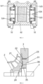
- the centrifugal compressor includes: a main shaft 1, an impeller 2, a diffuser 3, a thrust disk 4 and a supporting assembly 5.
- the main shaft 1 is provided with magnetic steel 13 along a middle position of the axial direction; the diffuser 3 is fixed on the shell 6; a first thrust bearing 10 is arranged at one end, away from a diffusion surface, of the diffuser 3; and the diffusion surface is an end face closed to the impeller 2.
- the supporting assembly 5 is arranged at one end, away from the diffusion surface, of the diffuser 3.
- One end of the supporting assembly 5 is fixed with the shell 6 of the compressor, and the other end of the supporting assembly 5 abuts against an end face of the diffuser 3.
- a second thrust bearing 10' is arranged on one side, facing towards the diffuser 3, of the supporting assembly 5.
- the thrust disk 4 is fixed with the main shaft 1 and is configured to rotate together with the main shaft 1.
- the thrust disk 4 is provided with a thrust portion 41, for example, a disk-shaped structure.
- a clearance between one side of the thrust portion 41 and the first thrust bearing 10 and a clearance between the other side of the thrust portion 41 and the second thrust bearing 10' are limited through mutual abutting of the diffuser 3 and the supporting assembly 5.
- left and right surfaces of the thrust portion 41 and the thrust bearings on two sides form working surfaces, which may withstand bidirectional axial forces, thus ensuring operational stability and reliability of the compressor under full working conditions and during reverse rotation.
- first thrust bearing 10 and the second thrust bearing 10' are static pressure or dynamic pressure gas thrust bearings, or magnetic levitation bearings.
- gas will form a gas film with a pressure in the clearance for thrusting and lubricating. Since the thrust bearing itself is in a cavity of the compressor and the cavity is full of the gas, the gas may be brought into the clearance to form a dynamic pressure gas thrust bearing in the rotation process of the rotor.
- the thrust disk cooperates with the thrust bearings on the two sides, which may bear axial forces in left and right directions, thus ensuring the operation stability of the compressor under full working conditions and during reverse rotation.
- the operation working conditions of the compressor refer to an evaporation temperature and a condensation temperature of a system where the compressor is located.
- the full working conditions refer to that the compressor works within a certain evaporation temperature range and a condensation temperature range.
- the diffuser 3 and the supporting assembly 5 need to be fixed on the shell 6 of the compressor, so the own position is fixed.
- the supporting assembly 5 and the diffuser 3 abut against each other for combined limitation, thus limiting the position of the thrust disk 4 and the clearances of the thrust bearings on the two sides. Therefore, the working clearance of the thrust bearings may be accurately ensured, the assembling difficulty is reduced, the assembling efficiency and the assembling precision are improved, and the working performance of the compressor is improved, thereby improving the operation stability of the compressor.
- a first groove 31 is formed at one end, away from a diffusion surface, of a diffuser 3
- a first thrust bearing 10 is arranged at the bottom of the first groove 31 along the axial direction
- a thrust portion 41 is located in the first groove 31, and there are a clearance between the one side of the thrust portion 41 and the first thrust bearing 10 and a clearance between the other side of the thrust portion 41 and the second thrust bearing 10'.
- the diffuser 3 and the supporting assembly 5 abut against each other, such that the clearances of the thrust bearings on two sides may be accurately ensured through an axial depth of the first groove 31, the assembling precision may be improved, the assembling difficulty is reduced, the assembling efficiency is improved, the performance of the thrust bearing can be ensured, and reduction, even failure of the performance of the thrust bearing caused by inaccurate clearance control is avoided, thus improving the operation stability of the compressor.
- a depth of the first groove 31 includes: a thickness of the thrust portion 41, a total thickness of the thrust bearings on two sides and the clearances of the thrust bearings on two sides; therefore, to ensure the clearances of the thrust bearings on two sides, the clearances may be controlled by the depth of the first groove 31, the thickness of the thrust portion 41 and the thicknesses of the thrust bearings on two sides.
- the specific method is: a design depth and a tolerance range of the first groove 31 are derived according to a clearance range which the thrust bearings need to reach, a thickness tolerance range of the thrust portion 41 and a thickness tolerance range of the thrust bearings. Therefore, clearances between the thrust bearings can be ensured by improving the machining precision of the depth of the first groove 31, the assembling precision may be improved and the assembling difficulty is reduced, thus improving the assembling efficiency.
- the centrifugal compressor further includes a shell 6 and a radial bearing 8 configured to bear a radial force of a rotor, wherein the radial force of the rotor mainly comes from the gravity of the rotor.
- the radial bearing 8 is a static pressure or dynamic pressure gas radial bearing, or a magnetic levitation bearing.
- the supporting assembly 5 includes a fixing plate 51 and a bearing support 52, wherein the fixing plate 51 abuts against the diffuser 3, and the second thrust bearing 10' is arranged on one side, facing towards the diffuser 3, of the fixing plate 51; and the bearing support 52 is arranged on one side, away from the diffuser 3, of the fixing plate 51, a first end of the bearing support 52 is connected to the fixing plate 51, and a second end of the bearing support 52 is connected to the shell 6, the bearing support 52 is configured to support a main shaft 1 through the radial bearing 8.
- the supporting assembly 5 adopts a split structure
- the second thrust bearing 10' is mounted through the fixing plate 51
- the radial bearings 8 are mounted on the bearing support 52, such that the mounting position precision, including the coaxiality of the two radial bearings 8 and the perpendicularity of the thrust bearings, of the radial bearings 8 at two ends of the main shaft 1 and the thrust bearings may be improved, and the working stability of the rotor system may be improved.
- a flange disk 525 is arranged at a second end of the bearing support 52, a spigot 527 is formed at an outer end of the flange disk 525, the bearing support 52 is mounted in a middle shell 62 through the flange disk 525 and is fixed through a fastener, and the bearing support 52 is radially located by the spigot 527.
- the two bearing supports 52 are assembled in the middle shell 62 through first location of the spigot 527 firstly, then the flange disk 525 and the middle shell 62 are fixed through the fasteners, and a pin is punched for fixation. Then, the middle shell 62 and the two bearing supports 52, serving as an whole assembly, are located on machining equipment, and end faces, contacting with the fixing plates 51, of the two bearing supports 52 are machined to ensure the perpendicularity of the thrust bearings and the radial bearings 8, and mounting holes 522 of the two bearing supports 52 are machined sequentially from one side to ensure the coaxiality of the two radial bearings 8.
- each the radial bearing 8 is mounted into the mounting holes 522 of the bearing supports 52 through a hot mounting manner, and then the fixing plate 51 are mounted at a first end of the bearing support 52.
- the bearing supports 52 are fixedly mounted on the shell 6 through the position of the pin determined during machining.
- the fixing plate 51 is further configured to limit a displacement of each of the radial bearings 8 towards one side of the diffuser 3 along the axial direction; therefore, the fixing plate 51 is capable of mounting the second thrust bearing 10' and also capable of axially limiting the radial bearings 8, such that the structure of the bearing supporting assembly may be more compact, and it is beneficial to ensure a parallelism of a mounting surface of the second thrust bearing 10' and an axial limiting surface of each of the radial bearings 8 through a machining parallelism of two sides of the fixing plate 51, thus improving the mounting precision of the thrust bearing and the radial bearings 8.
- a locating ring 511 is arranged at one end, facing towards the bearing support 52, of the fixing plate 51, the bearing support 52 is provided with an annular second groove 521, the locating ring 511 is arranged into the second groove 521 to radially locate the fixing plate 51, and there is a clearance between the fixing plate 51 and the main shaft 1. Furthermore, an inner wall of the locating ring 511 engages with an outer wall of a partial length section of the radial bearing 8 for supporting the partial length section of the radial bearing 8 and playing an axial thrust role in the radial bearing 8.
- the first thrust bearing 10 is fixed on the diffuser 3 through a fastener 32
- the second thrust bearing 10' is fixed on the fixing plate 51 through the fastener 32
- the fixing plate 51 and the diffuser 3 abut against each other
- a spigot 33 is formed at the periphery of the diffuser 3, thereby facilitating location and mounting of a shell 6.
- a fixing plate 51 and a bearing support 52 form an integrated structure.
- the supporting assembly 5 adopts an integrated structure, such that the structure may be simplified, the assembly difficulty may be reduced, and it is easy to ensure the perpendicularity of the radial bearing 8 and the thrust bearing through the machining precision of the supporting assembly 5.
- the centrifugal compressor further includes a shell 6 and a radial bearing 8.
- the supporting assembly 5 includes a bearing support 52, wherein a first end of the bearing support 52 abuts against a diffuser 3 and a second end of the bearing support 52 is connected to the shell 6; the second thrust bearing 10' is arranged on one side, facing towards the diffuser 3, of the bearing support 52; and the bearing support 52 is further configured to support a main shaft 1 through the radial bearing 8.
- a thrust platform is reserved on the bearing support 52 when a mounting hole 522 is machined so as to axially limit the radial bearing 8.
- a fixing plate 51 is omitted, such that an axial size of the bearing supporting assembly may be further reduced, the structure can be simplified, the assembling difficulty is reduced, and it is easy to ensure the perpendicularity of the radial bearing 8 and the thrust bearing through the machining precision of the supporting assembly 5.
- the centrifugal compressor further includes a shell 6 and a radial bearing 8.
- the supporting assembly 5 includes a bearing support 52, wherein a first end of the bearing support 52 abuts against a diffuser 3, and a second end of the bearing support 52 is connected to the shell 6 for supporting a main shaft 1 through the radial bearing 8. Since an outer diameter of the thrust bearing is less than an inner diameter of the shell 6, accordingly, outline dimensions of the bearing support 52 in a longitudinal section gradually increase from the first end to the second end, that is, radial outline dimensions of the bearing support 52 gradually increase from the first end to the second end thereof. To reduce the weight, as shown in FIG.
- a weight-reducing groove 524 is formed in one side, away from the thrust bearing, of the bearing support 52, for example, the weight-reducing groove 524 is arranged annularly, an inner wall of the weight-reducing groove 524 is parallel to a side wall of the mounting hole 522, and an outer wall of the weight-reducing groove 524 is consistent with an overall shape of the bearing support 52.
- the V-shaped bearing support 52 adopts a structure with gradually varied cross sectional area, such that the overall structural strength of the bearing support 52 may be improved, stress in all places is distributed uniformly and the bearing capacity may be optimized; moreover, an outer side wall is an inclined surface which is easily realized by casting, and has a draft angle when being cast by a mold.
- the bearing support 52 is provided with a vent hole 526 configured to communicate a space where the radial bearing 8 is located with a space where the first thrust bearing 10 and the second thrust bearing 10' are located, such that the working environment of the radial bearing 8 is consistent with those of the first thrust bearing 10 and the second thrust bearing 10', for example, the working back pressure of the radial bearing 8 is consistent with those of the first thrust bearing 10 and the second thrust bearing 10'.
- a refrigerant for cooling a motor enters and exits a motor cavity, when the compressor operates normally, pressure and temperature of the overall motor cavity are stable, the working environment of the thrust bearing and the radial bearing is as same as that of the motor cavity, that is, gas circulation is ensured, the back pressure is relatively stable, and fluctuation of a bearing gas film caused by too large fluctuation is reduced, thus improving the performance of the bearing.
- the bearing support 52 is provided with an operating hole 523 along a radial direction, such that a vibration sensor or a temperature sensor is mounted on an outer wall of the radial bearing 8 through the operating hole 523 to monitor the working state of the radial bearing 8.
- a hole section of the operating hole 523 along a radial outer side serves as a bypass hole so as to ensure that the pressure and temperature of the thrust bearing and the radial bearing 8 are as same as those of the motor cavity; and a hole section of the operating hole 523 along a radial inner side serves to dissipate heat for the radial bearing 8.
- the first thrust bearing 10 is directly fixed at the bottom of the first groove 31 of the diffuser 3.
- the first thrust bearing 10 adopts a dynamic pressure thrust bearing which is a flaky structure.
- the dynamic pressure thrust bearing is directly fixed at the bottom of the first groove 31.
- the diffuser 3 and the fixing plate of the thrust bearing are integrated into a part, the bottom of the first groove 31 may serve as the fixing plate of the first thrust bearing 10 without additionally setting the fixing plate of the thrust bearing, such that an axial size of the bearing supporting assembly may be further reduced and the structure is more compact.
- the centrifugal compressor further includes an impeller 2 and a locking part 9, wherein the main shaft 1 is internally provided with a cavity 11 and is provided with a shaft core 12 at the center, an end of the shaft core 12 extending out of an end of the main shaft 1; and the impeller 2 sleeves an outer end of the shaft core 12 and locks the impeller 2 on the shaft core 12 through the locking part 9, and the impeller 2 is located on an outer side of the diffuser 3.
- the impeller 2 may be detachably arranged relative to the main shaft 1, such that the assembling and disassembling difficulty of the impeller may be reduced, the assembling process of the impeller and the required equipment are simplified, and the assembling efficiency and the operability of the disassembling and inspection work and maintenance are improved.
- the mounting mode can prevent the main shaft 1 or the impeller 2 from being deformed, may ensure the mounting strength of the impeller 2 and may avoid stress concentration, thus improving the compression capacity of the compressor.
- the cavity 11 is formed in the main shaft 1, such that the weight of the main shaft 1 may be reduced, thus increasing the critical rotating speed of the main shaft 1 and further improving the ultimate working capacity of the compressor.
- the shaft core 12 is directly formed when the cavity 11 is machined, such that the shaft core 12 and the rest part of the main shaft 1 are machined into a whole body, it is unnecessary to additionally mount the shaft core 12 in the cavity of the main shaft 1, the assembling difficulty may be further reduced, the connection strength of the shaft core 12 and the main shaft 1 is improved, the position precision of the shaft core 12 may be ensured, the bounce problem of the front end of the rotor is effectively solved, and the length of a cantilever end is reduced, thus improving the working stability and reliability of the compressor.
- the cavity 11 is a ring groove, or a plurality of holes which are symmetrical relative to the center of an axis.
- the thrust disk 4 further includes a connection portion 42, wherein the connection portion 42 is connected to the thrust portion 41 and sleeves the main shaft 1; a through hole 34 is formed at the bottom of the first groove 31; and the connection portion 42 is arranged into the through hole 34.
- the connection portion 42 is in interference fit with the main shaft 1, such that the thrust disk 4 may rotate together with the main shaft 1.
- the diffuser 3 and the fixing plate 51 are fixedly arranged, and there is a clearance between the diffuser 3 and the main shaft 1.
- the thrust disk 4 has a cylindrical stepped structure.
- the centrifugal compressor further includes a sealing structure and an impeller 2 arranged on an end of the main shaft 1, wherein the impeller 2 is located on an outer side of the diffuser 3.
- a first axial comb-tooth sealing structure 35 is arranged on a side wall of the through hole 34 and forms a shaft seal with the thrust disk 4, thus reducing refrigerants from entering a motor cavity through the clearance between the diffuser 3 and the thrust disk 4 along with the exhaust of the impeller.
- a radial comb-tooth sealing structure 21 is arranged on an end, facing towards the diffuser 3, of the impeller 2, thus reducing refrigerants from flowing towards the periphery along with the clearance between the impeller 2 and the diffuser 3.
- the impeller 2 is provided with an protruding portion 22 arranged into the diffuser 3, for example, the protruding portion 22 is of an elongated strip structure extending along the axial direction, the protruding portion 22 is provided with a second axial comb-tooth sealing structure 23 on a radial inner side along a length direction of the protruding portion 22, thus reducing refrigerants from flowing towards the periphery along the clearance between the impeller 2 and the diffuser 3.
- the comb-tooth sealing structure includes a plurality of teeth arranged at intervals, wherein the teeth are trapezoidal; and one side wall of each tooth is a vertical surface, and the other side wall of each tooth is an inclined surface and inclines from a high-pressure side to a low-pressure side.
- the embodiment can reduce the leakage amount of the refrigerants between the impeller 2 and the diffuser 3 and between the diffuser 3 and the thrust disk 4, can ensure the clearance required for operation of the main shaft 1 and the impeller 2, and also can prevent leakage of the refrigerants caused by too large clearance, thereby effectively solving the sealing problem of the compressor and improving the energy efficiency of the compressor.
- the structure integrates the diffuser 3, the fixing plate of the thrust bearing and a shaft sealing part into a part, such that the mounting structure may be simplified, the structure is more compact and the assembling efficiency is improved.
- a spigot 33 is formed at the periphery of the diffuser 3 to facilitate location and mounting of the shell 6 and realize accurate location with the pin. Therefore, the coaxiality of the shaft sealing part on the diffuser 3 and the perpendicularity of a thrust bearing fixing surface are ensured on one part, and the machining difficulty and the assembling accumulated error are reduced.
- the shaft seal with high requirement on coaxiality and the thrust bearing with high requirement on perpendicularity are located jointly by the locating spigot 33 and the pin, the assembling standard is unified, the assembling difficulty is reduced and the assembling precision is improved, such that the perpendicularity of the thrust bearing fixing surface can be improved to ensure the working performance of the thrust bearing, and the coaxiality of the first axial comb-tooth sealing structure 35 can be improved to prevent the sealing property from being affected by the wear of the comb teeth.
- a material of the diffuser 3 has lower hardness than the thrust disk 4.
- the diffuser 3 adopts aluminum, and the thrust disk adopts 45 steel or 40 Cr, etc. In this way, if the first axial comb-tooth sealing structure 35 on the diffuser 3 and the main shaft 1 are worn, the comb teeth are worn firstly to prevent the main shaft 1 from being worn.
- the sealing structure simultaneously includes a first axial comb-tooth sealing structure 35, a radial comb-tooth sealing structure 21 and a second axial comb-tooth sealing structure 23, wherein the radial comb-tooth sealing structure 21 is located between the first axial comb-tooth sealing structure 35 and the second axial comb-tooth sealing structure 23 along a radial direction.
- This arrangement can make gas flow form a circuitous flow path so as to optimize the gas flow deceleration and depressurization effect and improve the sealing property.
- a boss 24 is arranged at one end, facing towards the diffuser 3, of the impeller 2, the boss 24 stretches into a third groove 36 of the diffuser 3, and the radial comb-tooth sealing structure 21 is arranged on an end part of the boss 24, such that the gas flow path is further lengthened while radial sealing is realized, the gas flow deceleration and depressurization effect is optimized, and the sealing property is improved.
- the present disclosure further provides air conditioning equipment, including the centrifugal compressor according to the above embodiments.
- the centrifugal compressor provided by the present disclosure may bear axial forces in two directions and ensure the operation stability of the compressor under full working conditions and during reverse rotation, and is capable of accurately ensuring the assembling clearance between the thrust bearings and ensuring the performance of the thrust bearings, thereby improving the operational stability of the compressor. The two factors can improve the working stability and reliability of the air conditioning equipment.
Landscapes
- Engineering & Computer Science (AREA)
- Mechanical Engineering (AREA)
- General Engineering & Computer Science (AREA)
- Physics & Mathematics (AREA)
- Fluid Mechanics (AREA)
- Structures Of Non-Positive Displacement Pumps (AREA)
Claims (12)
- Kreiselverdichter, umfassend:eine Hauptwelle (1);einen Diffusor (3), der an einem von einer Diffusionsfläche entfernten Ende mit einem ersten Axiallager (10) versehen ist;eine Halterungsanordnung (5), die an einem dem Diffusor (3) zugewandten Ende mit einem zweiten Axiallager (10') versehen ist; undeine Druckscheibe (4), die konfiguriert ist, um zusammen mit der Hauptwelle (1) zu drehen, und die zwischen dem Diffusor (3) und der Halterungsanordnung (5) entlang einer axialen Richtung angeordnet und mit einem Druckabschnitt (41) versehen ist, undwobei ein Spiel zwischen einer Seite der Druckscheibe (41) und dem ersten Axiallager (10') und ein Spiel zwischen der anderen Seite der Druckscheibe (41) und dem zweiten Axiallager (10) durch gegenseitiges Aneinanderstoßen des Diffusors (3) und der Befestigungsplatte (5) begrenzt sind;der Kreiselverdichter ferner umfassend ein Gehäuse (6) und ein Radiallager (8), wobei die Halterungsanordnung (5) Folgendes umfasst:eine Befestigungsplatte (51), die auf einer zum Diffusor (3) hin gerichteten Seite mit einem zweiten Axiallager (10') versehen ist; undeinen Lagerträger (52), der auf einer von dem Diffusor (3) abgewandten Seite der Befestigungsplatte (51) angeordnet ist, wobei ein erstes Ende des Lagerträgers (52) mit der Befestigungsplatte (51) verbunden ist und ein zweites Ende des Lagerträgers (52) mit dem Gehäuse (6) verbunden ist und konfiguriert ist, um die Hauptwelle (1) über das Radiallager (8) zu tragen;wobei der Kreiselverdichter dadurch gekennzeichnet ist, dass eine erste Nut (31) an einem von der Diffusionsfläche entfernten Ende des Diffusors (3) gebildet ist, das erste Axiallager (10) an dem Boden der ersten Nut (31) entlang der axialen Richtung angeordnet ist und der Druckabschnitt (41) in der ersten Nut (31) angeordnet ist.
- Kreiselverdichter nach Anspruch 1, wobei die Befestigungsplatte (51) und der Lagerträger (52) eine integrierte Struktur bilden.
- Kreiselverdichter nach Anspruch 1, wobei die Befestigungsplatte (51) konfiguriert ist, um eine Verschiebung des Radiallagers (8) zu einer Seite des Diffusors (3) entlang der axialen Richtung zu begrenzen;
optional wobei an einem dem Lagerträger (52) zugewandten Ende der Befestigungsplatte (51) ein Feststellring (511) angeordnet ist, der Lagerträger (52) mit einer ringförmigen zweiten Nut (521) versehen ist, der Feststellring (511) in der zweiten Nut (521) angeordnet ist und eine Innenwand (512) des Feststellrings (511) mit einer Außenwand eines Teillängenabschnitts des Radiallagers (8) eingreift. - Kreiselverdichter nach Anspruch 1, wobei ein erstes Ende des Lagerträgers (52) an dem Diffusor (3) anliegt, ein zweites Ende des Lagerträgers (52) mit dem Gehäuse (6) verbunden und konfiguriert ist, um die Hauptwelle (1) über das Radiallager (8) zu tragen, und die radialen Umrissabmessungen des Lagerträgers (52) von dem ersten Ende zu dem zweiten Ende desselben allmählich zunehmen.
- Kreiselverdichter nach Anspruch 1, wobei der Lagerträger (52) mit einem Entlüftungsloch (526) versehen ist, das konfiguriert ist, um einen Raum, in dem das Radiallager (8) angeordnet ist, mit einem Raum zu verbindet, in dem das erste Axiallager (10) und das zweite Axiallager (10') angeordnet sind.
- Kreiselverdichter nach Anspruch 1, ferner umfassend ein Laufrad (2) und einen Verriegelungsteil (9), wobei die Hauptwelle (1) innen mit einem Hohlraum (11) versehen ist und in der Mitte mit einem Wellenkern (12) versehen ist, wobei sich ein Ende des Wellenkerns (12) aus einem Ende der Hauptwelle (1) heraus erstreckt; und das Laufrad (2) ein äußeres Ende des Wellenkerns (12) umhüllt und das Laufrad (2) auf dem Wellenkern (12) durch das Verriegelungsteil (9) verriegelt, und das Laufrad (2) an einer Außenseite des Diffusors (3) angeordnet ist.
- Kreiselverdichter nach Anspruch 1, wobei das erste Axiallager (10) direkt an dem Boden der ersten Nut (31) befestigt ist.
- Kreiselverdichter nach Anspruch 1, wobei die Druckscheibe (4) ferner einen Verbindungsabschnitt (42) umfasst, wobei der Verbindungsabschnitt (42) mit dem Druckabschnitt (41) verbunden ist und die Hauptwelle (1) ummantelt; und ein Durchgangsloch (34) an dem Boden der ersten Nut (31) bereitgestellt ist und der Verbindungsabschnitt (42) in dem Durchgangsloch (34) angeordnet ist.
- Kreiselverdichter nach Anspruch 1, ferner umfassend eine Dichtungsstruktur und ein Laufrad (2), das an einem Ende der Hauptwelle (1) angeordnet ist, wobei das Laufrad (2) an einer Außenseite des Diffusors (3) angeordnet ist und die Dichtungsstruktur mindestens eine der folgenden Strukturen annimmt:eine erste axiale Kammzahn-Dichtungsstruktur (35), die an einer Seitenwand des Durchgangslochs (34) angeordnet ist;eine radiale Kammzahn-Dichtungsstruktur (21), die an einem dem Diffusor (3) zugewandten Ende des Laufrads (2) angeordnet ist; undeine zweite axiale Kammzahn-Dichtungsstruktur (23), wobei das Laufrad (2) mit einem in den Diffusor (3) angeordneten hervorstehenden Abschnitt (22) versehen ist und die zweite axiale Kammzahn-Dichtungsstruktur (23) auf dem hervorstehenden Abschnitt (22) entlang der axialen Richtung angeordnet ist.
- Kreiselverdichter nach Anspruch 9, wobei die Dichtungsstruktur Folgendes umfasst: die erste axiale Kammzahn-Dichtungsstruktur (35), die radiale Kammzahn-Dichtungsstruktur (21) und die zweite axiale Kammzahn-Dichtungsstruktur (23), und wobei die radiale Kammzahn-Dichtungsstruktur (21) zwischen der ersten axialen Kammzahn-Dichtungsstruktur (35) und der zweiten axialen Kammzahn-Dichtungsstruktur (23) entlang einer radialen Richtung angeordnet ist.
- Kreiselverdichter nach Anspruch 1, wobei mindestens eines von dem ersten Axiallager (10'), dem zweiten Axiallager (10) und dem Radiallager (8) ein Luftfederungslager ist.
- Klimaanlage, umfassend den Kreiselverdichter nach einem der Ansprüche 1 bis 11.
Applications Claiming Priority (2)
| Application Number | Priority Date | Filing Date | Title |
|---|---|---|---|
| CN201811593330.0A CN111365256B (zh) | 2018-12-25 | 2018-12-25 | 离心压缩机及空调设备 |
| PCT/CN2019/113018 WO2020134433A1 (zh) | 2018-12-25 | 2019-10-24 | 离心压缩机及空调设备 |
Publications (3)
| Publication Number | Publication Date |
|---|---|
| EP3904693A1 EP3904693A1 (de) | 2021-11-03 |
| EP3904693A4 EP3904693A4 (de) | 2022-02-16 |
| EP3904693B1 true EP3904693B1 (de) | 2025-06-04 |
Family
ID=71126849
Family Applications (1)
| Application Number | Title | Priority Date | Filing Date |
|---|---|---|---|
| EP19904130.2A Active EP3904693B1 (de) | 2018-12-25 | 2019-10-24 | Kreiselverdichter und klimaanlage |
Country Status (6)
| Country | Link |
|---|---|
| US (1) | US11608833B2 (de) |
| EP (1) | EP3904693B1 (de) |
| CN (1) | CN111365256B (de) |
| MY (1) | MY209235A (de) |
| PH (1) | PH12021551046A1 (de) |
| WO (1) | WO2020134433A1 (de) |
Families Citing this family (16)
| Publication number | Priority date | Publication date | Assignee | Title |
|---|---|---|---|---|
| CN111828393A (zh) * | 2020-08-20 | 2020-10-27 | 新奥能源动力科技(上海)有限公司 | 一种扩压器、叶轮以及离心压气机 |
| CN112160915B (zh) * | 2020-09-22 | 2025-07-11 | 珠海格力电器股份有限公司 | 压缩机 |
| DE102021201307A1 (de) * | 2021-02-11 | 2022-08-11 | Robert Bosch Gesellschaft mit beschränkter Haftung | Elektrisch angetriebene Luftzuführvorrichtung und Baukasten zur Herstellung |
| CN113417870B (zh) * | 2021-05-28 | 2022-04-12 | 海拓宾未来工业集团有限公司 | 一种基于空气悬浮轴承的纯无油高速压缩机 |
| CN113513499B (zh) * | 2021-07-02 | 2022-04-26 | 鑫磊压缩机股份有限公司 | 一种装配精度自矫正式压缩机 |
| CN113691059B (zh) * | 2021-07-29 | 2023-06-20 | 中国船舶重工集团公司第七0七研究所 | 一种减小转子涡动的动压气浮轴承改进结构 |
| CN114439761B (zh) * | 2022-01-14 | 2023-10-03 | 江苏海拓宾未来工业科技集团有限公司 | 一种双叶轮空气悬浮式低压纯无油离心压缩机 |
| CN114562467A (zh) * | 2022-03-01 | 2022-05-31 | 沈阳斯特机械制造有限公司 | 一种大压比垂直剖分离心压缩机 |
| CN114857042B (zh) * | 2022-04-21 | 2026-01-30 | 珠海格力电器股份有限公司 | 空气压缩机 |
| CN114922843B (zh) * | 2022-04-22 | 2023-03-31 | 烟台东德实业有限公司 | 一种高速离心空压机 |
| CN114857077B (zh) * | 2022-04-22 | 2023-01-10 | 烟台东德实业有限公司 | 一种稳定型高速离心空压机 |
| CN115585156A (zh) * | 2022-09-07 | 2023-01-10 | 深圳市英维克科技股份有限公司 | 压缩机及空调设备 |
| CN116447166B (zh) * | 2023-04-19 | 2024-08-13 | 烟台东德实业有限公司 | 一种空气压缩机叶轮轴向力平衡方法 |
| CN116658458A (zh) * | 2023-05-29 | 2023-08-29 | 鑫磊压缩机股份有限公司 | 一种双电机叶轮结构 |
| CN118793695B (zh) * | 2024-09-10 | 2025-01-07 | 宁波玉健健康科技股份有限公司 | 一种压轮套及应用该压轮套的制粒机 |
| CN120466216B (zh) * | 2025-07-16 | 2025-09-05 | 青岛海尔空调电子有限公司 | 气悬浮压缩机 |
Citations (2)
| Publication number | Priority date | Publication date | Assignee | Title |
|---|---|---|---|---|
| DE8328100U1 (de) * | 1983-09-30 | 1985-01-31 | MTU Motoren- und Turbinen-Union München GmbH, 8000 München | Abgasturbolader mit luftgelagertem Rotor |
| DE102015007379A1 (de) * | 2015-06-10 | 2016-01-21 | Daimler Ag | Strömungsmaschine für einen Energiewandler, insbesondere eine Brennstoffzelle |
Family Cites Families (23)
| Publication number | Priority date | Publication date | Assignee | Title |
|---|---|---|---|---|
| US4385768A (en) | 1979-07-19 | 1983-05-31 | Rotoflow Corporation, Inc. | Shaft mounting device and method |
| US4986733A (en) * | 1989-10-30 | 1991-01-22 | Allied-Signal, Inc. | Turbocharger compressor wheel assembly with boreless hub compressor wheel |
| KR20020024933A (ko) * | 2000-09-27 | 2002-04-03 | 구자홍 | 임펠러가 사용되는 터빈 압축기 구조 |
| KR100414110B1 (ko) | 2001-09-25 | 2004-01-07 | 엘지전자 주식회사 | 터보 압축기의 베어링 냉각구조 |
| CN1206457C (zh) * | 2002-05-31 | 2005-06-15 | 乐金电子(天津)电器有限公司 | 涡轮压缩机轴承的散热结构 |
| JP4932921B2 (ja) * | 2010-03-31 | 2012-05-16 | 本田技研工業株式会社 | 電動遠心圧縮機 |
| US8556516B2 (en) * | 2010-08-26 | 2013-10-15 | Hamilton Sundstrand Corporation | Compressor bearing cooling inlet plate |
| CN102242730A (zh) * | 2011-08-09 | 2011-11-16 | 中国南方航空工业(集团)有限公司 | 离心叶轮及具有其的离心压气机 |
| US9234522B2 (en) * | 2012-01-03 | 2016-01-12 | United Technologies Corporation | Hybrid bearing turbomachine |
| US8998494B2 (en) * | 2012-03-20 | 2015-04-07 | Flowserve Management Company | Dry gas thrust bearing for use in rotating equipment |
| US9157447B2 (en) * | 2012-10-19 | 2015-10-13 | Solar Turbines Incorporated | Centrifugal gas compressor magnetic bearing thrust collar with mounting pilots |
| US20170227012A1 (en) | 2014-09-08 | 2017-08-10 | Mitsubishi Heavy Industries Compressor Corporation | Rotary machine |
| CN104912838A (zh) * | 2015-05-19 | 2015-09-16 | 湖南大学 | 一种易拆卸剖分式空气箔片轴承以及具有该轴承的空压机 |
| DE102015016607A1 (de) * | 2015-12-22 | 2016-08-11 | Daimler Ag | Strömungsmaschine für einen Energiewandler und Verfahren zum Lagern eines Laufzeugs einer Strömungsmaschine |
| CN106015032B (zh) * | 2016-06-28 | 2018-05-22 | 杭州万辰机电科技有限公司 | 离心压缩机 |
| KR101970400B1 (ko) * | 2016-08-12 | 2019-08-13 | 한양대학교 에리카산학협력단 | 공기 베어링 및 회전체 시스템 |
| FR3055678B1 (fr) * | 2016-09-02 | 2020-09-18 | Danfoss Silicon Power Gmbh | Agencement de palier axial pour un arbre d'entrainement d'un compresseur centrifuge |
| CN106438446B (zh) | 2016-10-27 | 2018-12-14 | 重庆通用工业(集团)有限责任公司 | 离心压缩机径向支撑轴承 |
| CN108730222A (zh) | 2017-04-14 | 2018-11-02 | 开利公司 | 用于离心压缩机的密封组件及具有其的离心压缩机 |
| CN108252956A (zh) * | 2017-11-28 | 2018-07-06 | 湖南大学 | 一种空气箔片轴承支承空压机的转子自冷却系统 |
| CN107939699B (zh) * | 2017-12-04 | 2023-12-26 | 南京磁谷科技股份有限公司 | 一种磁悬浮压缩机结构 |
| CN108533510A (zh) * | 2018-05-18 | 2018-09-14 | 潍坊富源增压器有限公司 | 燃料电池用空气悬浮离心压缩机 |
| CN209340164U (zh) * | 2018-12-25 | 2019-09-03 | 珠海格力电器股份有限公司 | 离心压缩机及空调设备 |
-
2018
- 2018-12-25 CN CN201811593330.0A patent/CN111365256B/zh active Active
-
2019
- 2019-10-24 EP EP19904130.2A patent/EP3904693B1/de active Active
- 2019-10-24 US US17/295,723 patent/US11608833B2/en active Active
- 2019-10-24 WO PCT/CN2019/113018 patent/WO2020134433A1/zh not_active Ceased
- 2019-10-24 MY MYPI2021002490A patent/MY209235A/en unknown
-
2021
- 2021-05-06 PH PH12021551046A patent/PH12021551046A1/en unknown
Patent Citations (2)
| Publication number | Priority date | Publication date | Assignee | Title |
|---|---|---|---|---|
| DE8328100U1 (de) * | 1983-09-30 | 1985-01-31 | MTU Motoren- und Turbinen-Union München GmbH, 8000 München | Abgasturbolader mit luftgelagertem Rotor |
| DE102015007379A1 (de) * | 2015-06-10 | 2016-01-21 | Daimler Ag | Strömungsmaschine für einen Energiewandler, insbesondere eine Brennstoffzelle |
Also Published As
| Publication number | Publication date |
|---|---|
| US20220003238A1 (en) | 2022-01-06 |
| US11608833B2 (en) | 2023-03-21 |
| EP3904693A4 (de) | 2022-02-16 |
| CN111365256A (zh) | 2020-07-03 |
| MY209235A (en) | 2025-06-30 |
| EP3904693A1 (de) | 2021-11-03 |
| PH12021551046A1 (en) | 2021-12-06 |
| CN111365256B (zh) | 2025-07-25 |
| WO2020134433A1 (zh) | 2020-07-02 |
Similar Documents
| Publication | Publication Date | Title |
|---|---|---|
| EP3904693B1 (de) | Kreiselverdichter und klimaanlage | |
| US7351042B2 (en) | Structure of scroll of variable-throat exhaust turbocharger and method for manufacturing the turbocharger | |
| CN209340164U (zh) | 离心压缩机及空调设备 | |
| EP3938668B1 (de) | Folienlageranordnung und kompressor damit | |
| US5921683A (en) | Bearing arrangement for air cycle machine | |
| EP3904692B1 (de) | Lagerträgeranordnung und bearbeitungsverfahren dafür und zentrifugalverdichter | |
| EP4226049B1 (de) | Turboverdichteranordnung einer kühlmaschine | |
| CN112483415B (zh) | 基于一体化筒状支承座的液体火箭发动机低温涡轮泵 | |
| CN116897251A (zh) | 包括分段式内箔组件的箔轴承组件和包括该轴承组件的压缩机 | |
| EP4155547B1 (de) | Verdichter | |
| CN101268284A (zh) | 离心压缩机的叶轮 | |
| CN101297118A (zh) | 用于离心压缩机的静止密封环 | |
| CN211398277U (zh) | 转子组件、压缩机及空调设备 | |
| CN113107970B (zh) | 转子组件及其工作方法、压缩机及空调设备 | |
| CN121548696A (zh) | 具有一体式轮和迷宫式密封布置的用于涡轮机的旋转组 | |
| US20260043418A1 (en) | Rotation device | |
| CN223634934U (zh) | 一种燃料电池空压机 | |
| US12345170B2 (en) | Turbomachine with thrust bearing seal plate housing member having working fluid flow aperture | |
| CN219953749U (zh) | 止推侧轴承室气冷结构、双级离心空压机及止推侧轴承室端盖 | |
| CN121875826A (zh) | 一种涡轮增压器半浮动轴承连接定位结构 | |
| KR20260016465A (ko) | 터보 압축기 | |
| CN119664691A (zh) | 一种燃料电池空压机 | |
| WO2022224491A1 (ja) | 過給機 |
Legal Events
| Date | Code | Title | Description |
|---|---|---|---|
| STAA | Information on the status of an ep patent application or granted ep patent |
Free format text: STATUS: THE INTERNATIONAL PUBLICATION HAS BEEN MADE |
|
| PUAI | Public reference made under article 153(3) epc to a published international application that has entered the european phase |
Free format text: ORIGINAL CODE: 0009012 |
|
| STAA | Information on the status of an ep patent application or granted ep patent |
Free format text: STATUS: REQUEST FOR EXAMINATION WAS MADE |
|
| 17P | Request for examination filed |
Effective date: 20210507 |
|
| AK | Designated contracting states |
Kind code of ref document: A1 Designated state(s): AL AT BE BG CH CY CZ DE DK EE ES FI FR GB GR HR HU IE IS IT LI LT LU LV MC MK MT NL NO PL PT RO RS SE SI SK SM TR |
|
| A4 | Supplementary search report drawn up and despatched |
Effective date: 20220117 |
|
| RIC1 | Information provided on ipc code assigned before grant |
Ipc: F04D 17/10 20060101ALI20220111BHEP Ipc: F04D 29/62 20060101ALI20220111BHEP Ipc: F04D 29/44 20060101ALI20220111BHEP Ipc: F04D 29/08 20060101ALI20220111BHEP Ipc: F04D 29/051 20060101AFI20220111BHEP |
|
| DAV | Request for validation of the european patent (deleted) | ||
| DAX | Request for extension of the european patent (deleted) | ||
| P01 | Opt-out of the competence of the unified patent court (upc) registered |
Effective date: 20230530 |
|
| STAA | Information on the status of an ep patent application or granted ep patent |
Free format text: STATUS: EXAMINATION IS IN PROGRESS |
|
| 17Q | First examination report despatched |
Effective date: 20230829 |
|
| GRAP | Despatch of communication of intention to grant a patent |
Free format text: ORIGINAL CODE: EPIDOSNIGR1 |
|
| STAA | Information on the status of an ep patent application or granted ep patent |
Free format text: STATUS: GRANT OF PATENT IS INTENDED |
|
| INTG | Intention to grant announced |
Effective date: 20250317 |
|
| GRAS | Grant fee paid |
Free format text: ORIGINAL CODE: EPIDOSNIGR3 |
|
| GRAA | (expected) grant |
Free format text: ORIGINAL CODE: 0009210 |
|
| STAA | Information on the status of an ep patent application or granted ep patent |
Free format text: STATUS: THE PATENT HAS BEEN GRANTED |
|
| AK | Designated contracting states |
Kind code of ref document: B1 Designated state(s): AL AT BE BG CH CY CZ DE DK EE ES FI FR GB GR HR HU IE IS IT LI LT LU LV MC MK MT NL NO PL PT RO RS SE SI SK SM TR |
|
| REG | Reference to a national code |
Ref country code: GB Ref legal event code: FG4D |
|
| REG | Reference to a national code |
Ref country code: CH Ref legal event code: EP |
|
| REG | Reference to a national code |
Ref country code: DE Ref legal event code: R096 Ref document number: 602019070913 Country of ref document: DE |
|
| REG | Reference to a national code |
Ref country code: IE Ref legal event code: FG4D |
|
| REG | Reference to a national code |
Ref country code: NL Ref legal event code: MP Effective date: 20250604 |
|
| PG25 | Lapsed in a contracting state [announced via postgrant information from national office to epo] |
Ref country code: ES Free format text: LAPSE BECAUSE OF FAILURE TO SUBMIT A TRANSLATION OF THE DESCRIPTION OR TO PAY THE FEE WITHIN THE PRESCRIBED TIME-LIMIT Effective date: 20250604 Ref country code: FI Free format text: LAPSE BECAUSE OF FAILURE TO SUBMIT A TRANSLATION OF THE DESCRIPTION OR TO PAY THE FEE WITHIN THE PRESCRIBED TIME-LIMIT Effective date: 20250604 |
|
| REG | Reference to a national code |
Ref country code: LT Ref legal event code: MG9D |
|
| PG25 | Lapsed in a contracting state [announced via postgrant information from national office to epo] |
Ref country code: GR Free format text: LAPSE BECAUSE OF FAILURE TO SUBMIT A TRANSLATION OF THE DESCRIPTION OR TO PAY THE FEE WITHIN THE PRESCRIBED TIME-LIMIT Effective date: 20250905 Ref country code: NO Free format text: LAPSE BECAUSE OF FAILURE TO SUBMIT A TRANSLATION OF THE DESCRIPTION OR TO PAY THE FEE WITHIN THE PRESCRIBED TIME-LIMIT Effective date: 20250904 |
|
| PG25 | Lapsed in a contracting state [announced via postgrant information from national office to epo] |
Ref country code: PL Free format text: LAPSE BECAUSE OF FAILURE TO SUBMIT A TRANSLATION OF THE DESCRIPTION OR TO PAY THE FEE WITHIN THE PRESCRIBED TIME-LIMIT Effective date: 20250604 |
|
| PG25 | Lapsed in a contracting state [announced via postgrant information from national office to epo] |
Ref country code: BG Free format text: LAPSE BECAUSE OF FAILURE TO SUBMIT A TRANSLATION OF THE DESCRIPTION OR TO PAY THE FEE WITHIN THE PRESCRIBED TIME-LIMIT Effective date: 20250604 |
|
| PG25 | Lapsed in a contracting state [announced via postgrant information from national office to epo] |
Ref country code: HR Free format text: LAPSE BECAUSE OF FAILURE TO SUBMIT A TRANSLATION OF THE DESCRIPTION OR TO PAY THE FEE WITHIN THE PRESCRIBED TIME-LIMIT Effective date: 20250604 |
|
| PGFP | Annual fee paid to national office [announced via postgrant information from national office to epo] |
Ref country code: FR Payment date: 20250929 Year of fee payment: 7 |
|
| PG25 | Lapsed in a contracting state [announced via postgrant information from national office to epo] |
Ref country code: RS Free format text: LAPSE BECAUSE OF FAILURE TO SUBMIT A TRANSLATION OF THE DESCRIPTION OR TO PAY THE FEE WITHIN THE PRESCRIBED TIME-LIMIT Effective date: 20250904 |
|
| PG25 | Lapsed in a contracting state [announced via postgrant information from national office to epo] |
Ref country code: LV Free format text: LAPSE BECAUSE OF FAILURE TO SUBMIT A TRANSLATION OF THE DESCRIPTION OR TO PAY THE FEE WITHIN THE PRESCRIBED TIME-LIMIT Effective date: 20250604 |
|
| PG25 | Lapsed in a contracting state [announced via postgrant information from national office to epo] |
Ref country code: NL Free format text: LAPSE BECAUSE OF FAILURE TO SUBMIT A TRANSLATION OF THE DESCRIPTION OR TO PAY THE FEE WITHIN THE PRESCRIBED TIME-LIMIT Effective date: 20250604 |
|
| PG25 | Lapsed in a contracting state [announced via postgrant information from national office to epo] |
Ref country code: PT Free format text: LAPSE BECAUSE OF FAILURE TO SUBMIT A TRANSLATION OF THE DESCRIPTION OR TO PAY THE FEE WITHIN THE PRESCRIBED TIME-LIMIT Effective date: 20251006 |
|
| REG | Reference to a national code |
Ref country code: AT Ref legal event code: MK05 Ref document number: 1800566 Country of ref document: AT Kind code of ref document: T Effective date: 20250604 |
|
| PG25 | Lapsed in a contracting state [announced via postgrant information from national office to epo] |
Ref country code: IS Free format text: LAPSE BECAUSE OF FAILURE TO SUBMIT A TRANSLATION OF THE DESCRIPTION OR TO PAY THE FEE WITHIN THE PRESCRIBED TIME-LIMIT Effective date: 20251004 |
|
| PGFP | Annual fee paid to national office [announced via postgrant information from national office to epo] |
Ref country code: DE Payment date: 20251015 Year of fee payment: 7 |
|
| PGFP | Annual fee paid to national office [announced via postgrant information from national office to epo] |
Ref country code: GB Payment date: 20251023 Year of fee payment: 7 |
|
| PG25 | Lapsed in a contracting state [announced via postgrant information from national office to epo] |
Ref country code: SM Free format text: LAPSE BECAUSE OF FAILURE TO SUBMIT A TRANSLATION OF THE DESCRIPTION OR TO PAY THE FEE WITHIN THE PRESCRIBED TIME-LIMIT Effective date: 20250604 Ref country code: AT Free format text: LAPSE BECAUSE OF FAILURE TO SUBMIT A TRANSLATION OF THE DESCRIPTION OR TO PAY THE FEE WITHIN THE PRESCRIBED TIME-LIMIT Effective date: 20250604 |
|
| PG25 | Lapsed in a contracting state [announced via postgrant information from national office to epo] |
Ref country code: CZ Free format text: LAPSE BECAUSE OF FAILURE TO SUBMIT A TRANSLATION OF THE DESCRIPTION OR TO PAY THE FEE WITHIN THE PRESCRIBED TIME-LIMIT Effective date: 20250604 |
|
| PG25 | Lapsed in a contracting state [announced via postgrant information from national office to epo] |
Ref country code: EE Free format text: LAPSE BECAUSE OF FAILURE TO SUBMIT A TRANSLATION OF THE DESCRIPTION OR TO PAY THE FEE WITHIN THE PRESCRIBED TIME-LIMIT Effective date: 20250604 |
|
| PG25 | Lapsed in a contracting state [announced via postgrant information from national office to epo] |
Ref country code: SK Free format text: LAPSE BECAUSE OF FAILURE TO SUBMIT A TRANSLATION OF THE DESCRIPTION OR TO PAY THE FEE WITHIN THE PRESCRIBED TIME-LIMIT Effective date: 20250604 Ref country code: RO Free format text: LAPSE BECAUSE OF FAILURE TO SUBMIT A TRANSLATION OF THE DESCRIPTION OR TO PAY THE FEE WITHIN THE PRESCRIBED TIME-LIMIT Effective date: 20250604 |
|
| PG25 | Lapsed in a contracting state [announced via postgrant information from national office to epo] |
Ref country code: IT Free format text: LAPSE BECAUSE OF FAILURE TO SUBMIT A TRANSLATION OF THE DESCRIPTION OR TO PAY THE FEE WITHIN THE PRESCRIBED TIME-LIMIT Effective date: 20250604 |
|
| REG | Reference to a national code |
Ref country code: DE Ref legal event code: R097 Ref document number: 602019070913 Country of ref document: DE |
|
| PLBE | No opposition filed within time limit |
Free format text: ORIGINAL CODE: 0009261 |
|
| STAA | Information on the status of an ep patent application or granted ep patent |
Free format text: STATUS: NO OPPOSITION FILED WITHIN TIME LIMIT |
|
| PG25 | Lapsed in a contracting state [announced via postgrant information from national office to epo] |
Ref country code: DK Free format text: LAPSE BECAUSE OF FAILURE TO SUBMIT A TRANSLATION OF THE DESCRIPTION OR TO PAY THE FEE WITHIN THE PRESCRIBED TIME-LIMIT Effective date: 20250604 |
|
| REG | Reference to a national code |
Ref country code: CH Ref legal event code: L10 Free format text: ST27 STATUS EVENT CODE: U-0-0-L10-L00 (AS PROVIDED BY THE NATIONAL OFFICE) Effective date: 20260416 |