EP3904665A1 - Exhaust gas recirculation system and engine - Google Patents
Exhaust gas recirculation system and engine Download PDFInfo
- Publication number
- EP3904665A1 EP3904665A1 EP18945077.8A EP18945077A EP3904665A1 EP 3904665 A1 EP3904665 A1 EP 3904665A1 EP 18945077 A EP18945077 A EP 18945077A EP 3904665 A1 EP3904665 A1 EP 3904665A1
- Authority
- EP
- European Patent Office
- Prior art keywords
- egr
- turbocharger
- exhaust gas
- pipe
- exhaust
- Prior art date
- Legal status (The legal status is an assumption and is not a legal conclusion. Google has not performed a legal analysis and makes no representation as to the accuracy of the status listed.)
- Pending
Links
Images



Classifications
-
- F—MECHANICAL ENGINEERING; LIGHTING; HEATING; WEAPONS; BLASTING
- F02—COMBUSTION ENGINES; HOT-GAS OR COMBUSTION-PRODUCT ENGINE PLANTS
- F02M—SUPPLYING COMBUSTION ENGINES IN GENERAL WITH COMBUSTIBLE MIXTURES OR CONSTITUENTS THEREOF
- F02M26/00—Engine-pertinent apparatus for adding exhaust gases to combustion-air, main fuel or fuel-air mixture, e.g. by exhaust gas recirculation [EGR] systems
- F02M26/13—Arrangement or layout of EGR passages, e.g. in relation to specific engine parts or for incorporation of accessories
- F02M26/34—Arrangement or layout of EGR passages, e.g. in relation to specific engine parts or for incorporation of accessories with compressors, turbines or the like in the recirculation passage
-
- F—MECHANICAL ENGINEERING; LIGHTING; HEATING; WEAPONS; BLASTING
- F02—COMBUSTION ENGINES; HOT-GAS OR COMBUSTION-PRODUCT ENGINE PLANTS
- F02M—SUPPLYING COMBUSTION ENGINES IN GENERAL WITH COMBUSTIBLE MIXTURES OR CONSTITUENTS THEREOF
- F02M26/00—Engine-pertinent apparatus for adding exhaust gases to combustion-air, main fuel or fuel-air mixture, e.g. by exhaust gas recirculation [EGR] systems
- F02M26/02—EGR systems specially adapted for supercharged engines
-
- F—MECHANICAL ENGINEERING; LIGHTING; HEATING; WEAPONS; BLASTING
- F01—MACHINES OR ENGINES IN GENERAL; ENGINE PLANTS IN GENERAL; STEAM ENGINES
- F01N—GAS-FLOW SILENCERS OR EXHAUST APPARATUS FOR MACHINES OR ENGINES IN GENERAL; GAS-FLOW SILENCERS OR EXHAUST APPARATUS FOR INTERNAL-COMBUSTION ENGINES
- F01N13/00—Exhaust or silencing apparatus characterised by constructional features
- F01N13/08—Other arrangements or adaptations of exhaust conduits
- F01N13/10—Other arrangements or adaptations of exhaust conduits of exhaust manifolds
-
- F—MECHANICAL ENGINEERING; LIGHTING; HEATING; WEAPONS; BLASTING
- F02—COMBUSTION ENGINES; HOT-GAS OR COMBUSTION-PRODUCT ENGINE PLANTS
- F02B—INTERNAL-COMBUSTION PISTON ENGINES; COMBUSTION ENGINES IN GENERAL
- F02B37/00—Engines characterised by provision of pumps driven at least for part of the time by exhaust
- F02B37/004—Engines characterised by provision of pumps driven at least for part of the time by exhaust with exhaust drives arranged in series
-
- F—MECHANICAL ENGINEERING; LIGHTING; HEATING; WEAPONS; BLASTING
- F02—COMBUSTION ENGINES; HOT-GAS OR COMBUSTION-PRODUCT ENGINE PLANTS
- F02B—INTERNAL-COMBUSTION PISTON ENGINES; COMBUSTION ENGINES IN GENERAL
- F02B37/00—Engines characterised by provision of pumps driven at least for part of the time by exhaust
- F02B37/12—Control of the pumps
- F02B37/18—Control of the pumps by bypassing exhaust from the inlet to the outlet of turbine or to the atmosphere
-
- F—MECHANICAL ENGINEERING; LIGHTING; HEATING; WEAPONS; BLASTING
- F02—COMBUSTION ENGINES; HOT-GAS OR COMBUSTION-PRODUCT ENGINE PLANTS
- F02M—SUPPLYING COMBUSTION ENGINES IN GENERAL WITH COMBUSTIBLE MIXTURES OR CONSTITUENTS THEREOF
- F02M26/00—Engine-pertinent apparatus for adding exhaust gases to combustion-air, main fuel or fuel-air mixture, e.g. by exhaust gas recirculation [EGR] systems
- F02M26/02—EGR systems specially adapted for supercharged engines
- F02M26/04—EGR systems specially adapted for supercharged engines with a single turbocharger
- F02M26/05—High pressure loops, i.e. wherein recirculated exhaust gas is taken out from the exhaust system upstream of the turbine and reintroduced into the intake system downstream of the compressor
-
- F—MECHANICAL ENGINEERING; LIGHTING; HEATING; WEAPONS; BLASTING
- F02—COMBUSTION ENGINES; HOT-GAS OR COMBUSTION-PRODUCT ENGINE PLANTS
- F02M—SUPPLYING COMBUSTION ENGINES IN GENERAL WITH COMBUSTIBLE MIXTURES OR CONSTITUENTS THEREOF
- F02M26/00—Engine-pertinent apparatus for adding exhaust gases to combustion-air, main fuel or fuel-air mixture, e.g. by exhaust gas recirculation [EGR] systems
- F02M26/02—EGR systems specially adapted for supercharged engines
- F02M26/08—EGR systems specially adapted for supercharged engines for engines having two or more intake charge compressors or exhaust gas turbines, e.g. a turbocharger combined with an additional compressor
-
- F—MECHANICAL ENGINEERING; LIGHTING; HEATING; WEAPONS; BLASTING
- F02—COMBUSTION ENGINES; HOT-GAS OR COMBUSTION-PRODUCT ENGINE PLANTS
- F02M—SUPPLYING COMBUSTION ENGINES IN GENERAL WITH COMBUSTIBLE MIXTURES OR CONSTITUENTS THEREOF
- F02M26/00—Engine-pertinent apparatus for adding exhaust gases to combustion-air, main fuel or fuel-air mixture, e.g. by exhaust gas recirculation [EGR] systems
- F02M26/13—Arrangement or layout of EGR passages, e.g. in relation to specific engine parts or for incorporation of accessories
- F02M26/14—Arrangement or layout of EGR passages, e.g. in relation to specific engine parts or for incorporation of accessories in relation to the exhaust system
-
- F—MECHANICAL ENGINEERING; LIGHTING; HEATING; WEAPONS; BLASTING
- F02—COMBUSTION ENGINES; HOT-GAS OR COMBUSTION-PRODUCT ENGINE PLANTS
- F02M—SUPPLYING COMBUSTION ENGINES IN GENERAL WITH COMBUSTIBLE MIXTURES OR CONSTITUENTS THEREOF
- F02M26/00—Engine-pertinent apparatus for adding exhaust gases to combustion-air, main fuel or fuel-air mixture, e.g. by exhaust gas recirculation [EGR] systems
- F02M26/13—Arrangement or layout of EGR passages, e.g. in relation to specific engine parts or for incorporation of accessories
- F02M26/17—Arrangement or layout of EGR passages, e.g. in relation to specific engine parts or for incorporation of accessories in relation to the intake system
-
- F—MECHANICAL ENGINEERING; LIGHTING; HEATING; WEAPONS; BLASTING
- F02—COMBUSTION ENGINES; HOT-GAS OR COMBUSTION-PRODUCT ENGINE PLANTS
- F02M—SUPPLYING COMBUSTION ENGINES IN GENERAL WITH COMBUSTIBLE MIXTURES OR CONSTITUENTS THEREOF
- F02M26/00—Engine-pertinent apparatus for adding exhaust gases to combustion-air, main fuel or fuel-air mixture, e.g. by exhaust gas recirculation [EGR] systems
- F02M26/13—Arrangement or layout of EGR passages, e.g. in relation to specific engine parts or for incorporation of accessories
- F02M26/22—Arrangement or layout of EGR passages, e.g. in relation to specific engine parts or for incorporation of accessories with coolers in the recirculation passage
-
- F—MECHANICAL ENGINEERING; LIGHTING; HEATING; WEAPONS; BLASTING
- F02—COMBUSTION ENGINES; HOT-GAS OR COMBUSTION-PRODUCT ENGINE PLANTS
- F02M—SUPPLYING COMBUSTION ENGINES IN GENERAL WITH COMBUSTIBLE MIXTURES OR CONSTITUENTS THEREOF
- F02M26/00—Engine-pertinent apparatus for adding exhaust gases to combustion-air, main fuel or fuel-air mixture, e.g. by exhaust gas recirculation [EGR] systems
- F02M26/13—Arrangement or layout of EGR passages, e.g. in relation to specific engine parts or for incorporation of accessories
- F02M26/35—Arrangement or layout of EGR passages, e.g. in relation to specific engine parts or for incorporation of accessories with means for cleaning or treating the recirculated gases, e.g. catalysts, condensate traps, particle filters or heaters
-
- F—MECHANICAL ENGINEERING; LIGHTING; HEATING; WEAPONS; BLASTING
- F02—COMBUSTION ENGINES; HOT-GAS OR COMBUSTION-PRODUCT ENGINE PLANTS
- F02M—SUPPLYING COMBUSTION ENGINES IN GENERAL WITH COMBUSTIBLE MIXTURES OR CONSTITUENTS THEREOF
- F02M31/00—Apparatus for thermally treating combustion-air, fuel, or fuel-air mixture
- F02M31/20—Apparatus for thermally treating combustion-air, fuel, or fuel-air mixture for cooling
-
- F—MECHANICAL ENGINEERING; LIGHTING; HEATING; WEAPONS; BLASTING
- F02—COMBUSTION ENGINES; HOT-GAS OR COMBUSTION-PRODUCT ENGINE PLANTS
- F02M—SUPPLYING COMBUSTION ENGINES IN GENERAL WITH COMBUSTIBLE MIXTURES OR CONSTITUENTS THEREOF
- F02M35/00—Combustion-air cleaners, air intakes, intake silencers, or induction systems specially adapted for, or arranged on, internal-combustion engines
- F02M35/10—Air intakes; Induction systems
- F02M35/1015—Air intakes; Induction systems characterised by the engine type
- F02M35/10157—Supercharged engines
-
- F—MECHANICAL ENGINEERING; LIGHTING; HEATING; WEAPONS; BLASTING
- F02—COMBUSTION ENGINES; HOT-GAS OR COMBUSTION-PRODUCT ENGINE PLANTS
- F02M—SUPPLYING COMBUSTION ENGINES IN GENERAL WITH COMBUSTIBLE MIXTURES OR CONSTITUENTS THEREOF
- F02M35/00—Combustion-air cleaners, air intakes, intake silencers, or induction systems specially adapted for, or arranged on, internal-combustion engines
- F02M35/10—Air intakes; Induction systems
- F02M35/10209—Fluid connections to the air intake system; their arrangement of pipes, valves or the like
- F02M35/10222—Exhaust gas recirculation [EGR]; Positive crankcase ventilation [PCV]; Additional air admission, lubricant or fuel vapour admission
-
- F—MECHANICAL ENGINEERING; LIGHTING; HEATING; WEAPONS; BLASTING
- F02—COMBUSTION ENGINES; HOT-GAS OR COMBUSTION-PRODUCT ENGINE PLANTS
- F02B—INTERNAL-COMBUSTION PISTON ENGINES; COMBUSTION ENGINES IN GENERAL
- F02B37/00—Engines characterised by provision of pumps driven at least for part of the time by exhaust
- F02B37/12—Control of the pumps
- F02B37/16—Control of the pumps by bypassing charging air
- F02B37/168—Control of the pumps by bypassing charging air into the exhaust conduit
-
- Y—GENERAL TAGGING OF NEW TECHNOLOGICAL DEVELOPMENTS; GENERAL TAGGING OF CROSS-SECTIONAL TECHNOLOGIES SPANNING OVER SEVERAL SECTIONS OF THE IPC; TECHNICAL SUBJECTS COVERED BY FORMER USPC CROSS-REFERENCE ART COLLECTIONS [XRACs] AND DIGESTS
- Y02—TECHNOLOGIES OR APPLICATIONS FOR MITIGATION OR ADAPTATION AGAINST CLIMATE CHANGE
- Y02T—CLIMATE CHANGE MITIGATION TECHNOLOGIES RELATED TO TRANSPORTATION
- Y02T10/00—Road transport of goods or passengers
- Y02T10/10—Internal combustion engine [ICE] based vehicles
- Y02T10/12—Improving ICE efficiencies
Definitions
- the present application relates to the technical field of engine EGR, in particular to an exhaust gas recirculation system and an engine.
- Exhaust gas recirculation is one of the most effective means for a modern diesel engine to reduce NO x emission.
- EGR can reduce the oxygen concentration and the maximum combustion temperature in a cylinder, thereby achieving the effect of reducing NO x .
- EGR is considered to be one of the important technical means for the diesel engine to meet national IV regulation and later emission regulations.
- an exhaust manifold 03 of an engine 01 is connected with a turbine 06 of a turbocharger, an exhaust pipe 07 is connected after the turbine 06, one end of an EGR pipe 010 takes air before the turbine 06, the other end of the EGR pipe 010 is connected to an intake manifold 02 of the engine 01.
- An EGR valve 04 is provided on the EGR pipe, an inlet of a compressor 05 of the turbocharger is connected with an intake pipe 08, and an outlet of the compressor 05 is in communication with the intake manifold 02.
- the common method is to provide an intake throttle valve 09 on the intake pipe.
- the EGR exhaust gas is mixed with the supercharged air downstream of the intake throttle valve 09.
- the intake throttle valve 09 may significantly increase the pumping loss while increasing the EGR rate, which causes the engine fuel consumption to be increased, the particulate matter emission to be increased, and the economy to be deteriorated.
- a first object of the present application is to provide an exhaust gas recirculation system to increase the EGR rate while avoiding pumping loss, increased engine fuel consumption, increased particulate matter emission, and improve economy of an engine.
- a second object of the present application is to provide an engine including the above exhaust gas recirculation system.
- An exhaust gas recirculation system includes a first turbocharger and a second turbocharger.
- a turbine of the first turbocharger and a turbine of the second turbocharger are connected in series to an exhaust manifold of an engine, an outlet of the turbine of the second turbocharger is connected to an exhaust pipe, an inlet of a compressor of the first turbocharger is connected to an intake pipe, an outlet of the compressor of the first turbocharger is in communication with an intake manifold of the engine, an inlet of a compressor of the second turbocharger is in communication with the exhaust manifold through a first EGR intake pipe, and an outlet of the compressor of the second turbocharger is in communication with the intake manifold through an EGR exhaust pipe.
- a pipeline between the turbine of the first turbocharger and the turbine of the second turbocharger is communicated with the exhaust pipe through a bypass pipe, and an exhaust gas control valve is provided on the bypass pipe.
- the inlet of the second turbocharger is in communication with the exhaust pipe through a second EGR intake pipe.
- an EGR filter is provided on at least one of the first EGR intake pipe and the second EGR intake pipe.
- an EGR filter is provided on the EGR exhaust pipe.
- an EGR cooler is provided on at least one of the first EGR intake pipe, the second EGR intake pipe and the EGR exhaust pipe.
- the outlet of the compressor of the first turbocharger is in communication with the intake manifold through an intercooler, and the EGR exhaust pipe and the intake manifold are connected downstream of the intercooler in an intake direction.
- the outlet of the compressor of the first turbocharger is communicated with the intake manifold through an intercooler, and the EGR exhaust pipe and the intake manifold are connected upstream of the intercooler in an intake direction.
- an EGR valve is provided on the EGR exhaust pipe.
- An engine includes the exhaust gas recirculation system according to any one of the above.
- the exhaust gas recirculation system is provided according to the present application, which includes the first turbocharger and the second turbocharger.
- the turbine of the first turbocharger and the turbine of the second turbocharger are connected in series to the exhaust manifold of the engine, that is, an inlet of the turbine of the first turbocharger is in communication with the exhaust manifold, an outlet of the turbine of the first turbocharger is in communication with an inlet of the turbine of the second turbocharger, the inlet of the compressor of the first turbocharger is connected with the intake pipe, the outlet of the compressor of the first turbocharger is in communication with the intake manifold of the engine, the inlet of the compressor of the second turbocharger is in communication with the exhaust manifold through the first EGR intake pipe, and the outlet of the compressor of the second turbocharger is in communication with the intake manifold through the EGR exhaust pipe.
- a two-stage turbocharger is used by the above exhaust gas recirculation system.
- part of the exhaust gas discharged from the exhaust manifold is used by the first turbocharger to supercharge the fresh air, and then the exhaust gas enters the turbine of the second turbocharger to continue to recover the energy of the exhaust gas.
- Part of the exhaust gas taken from the exhaust manifold through the first EGR intake pipe in the compressor of the second turbocharger is supercharged, and the supercharged exhaust gas is mixed with the fresh air and passed into the exhaust manifold.
- the energy of the exhaust gas is reused by the above exhaust gas recirculation system to drive the turbine of the two-stage turbocharger, which improves the utilization rate of the exhaust gas.
- the exhaust gas is supercharged by the second turbocharger, which is beneficial to increasing the EGR exhaust pressure, increasing the pressure difference between the exhaust and intake and the amount of the exhaust gas entering the engine, and increasing the EGR rate without adding an intake throttle valve, thereby avoiding pumping loss, increased engine fuel consumption, increased particulate matter emission while increasing the EGR rate, and improving economy of the engine.
- An engine is further provided according to the present application, which includes the above exhaust gas recirculation system. Since the above exhaust gas recirculation system has the above technical effects, the engine with the exhaust gas recirculation system also has corresponding technical effects.
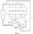
- FIG 2 is a schematic structural diagram of an exhaust gas recirculation system provided according to a first embodiment of the present application.
- An exhaust gas recirculation system provided according to an embodiment of the present application includes a first turbocharger 7 and a second turbocharger 6.
- a turbine 701 of the first turbocharger 7 and a turbine 601 of the second turbocharger 6 are connected in series to an exhaust manifold 3 of an engine 1, that is, an inlet of the turbine 701 of the first turbocharger 7 is in communication with the exhaust manifold 3, an outlet of the turbine 701 of the first turbocharger 7 is in communication with an inlet of the turbine 601 of the second turbocharger 6, an outlet of the turbine 601 of the second turbocharger 6 is in communication with an exhaust pipe 9, an inlet of a compressor 702 of the first turbocharger 7 is connected with an intake pipe 8, an outlet of the compressor 702 of the first turbocharger 7 is in communication with an intake manifold 2 of the engine 1, an inlet of a compressor 602 of the second turbocharger 6 is in communication with the exhaust manifold 3 through a first EGR intake pipe 4, and an outlet of the compressor 602 of the second turbocharger 6 is in communication with the intake manifold 2 through an EGR exhaust pipe 5.
- a two-stage turbocharger is used by the exhaust gas recirculation system provided according to the embodiment of the present application.
- part of exhaust gas discharged from the exhaust manifold 3 is used by the first turbocharger 7 to supercharge the fresh air, and then the exhaust gas enters the turbine 601 of the second turbocharger 6 to continue to recover the energy of the exhaust gas.
- Part of the exhaust gas taken from the exhaust manifold 3 through the first EGR intake pipe 4 in the compressor 602 of the second turbocharger 6 is supercharged, and the supercharged exhaust gas is mixed with the fresh air and passed into the exhaust manifold 3.
- the energy of the exhaust gas is reused by the above exhaust gas recirculation system to drive the turbine of the two-stage turbocharger, which improves the utilization rate of the exhaust gas.
- the exhaust gas is supercharged by the second turbocharger 6, which is beneficial to increasing the EGR exhaust pressure, increasing the pressure difference between the exhaust and intake and the amount of the exhaust gas entering the engine 1, and improving the EGR rate without adding an intake throttle valve, thereby avoiding pumping loss, increased engine fuel consumption, increased particulate matter emission while increasing the EGR rate, and improving economy of the engine 1.
- a pipeline between the turbine 701 of the first turbocharger 7 and the turbine 601 of the second turbocharger 6 is in communication with an exhaust pipe 9 through a bypass pipe 11, and an exhaust gas control valve 12 is provided on the bypass pipe 11. If the EGR rate is insufficient in use, the exhaust gas control valve 12 is closed, the exhaust gas discharged from the turbine 701 of the first turbocharger 7 enters the turbine 601 of the second turbocharger 6 for supercharging the EGR exhaust gas. If the EGR rate is sufficient, the exhaust gas control valve 12 is opened, the exhaust gas is directly discharged without passing through the turbine 601 of the second turbocharger 6, so as to reduce the exhaust resistance.
- the bypass pipe 11 may be in communication with the exhaust pipe 9, or may be in direct communication with the external environment.
- an inlet of the second turbocharger 6 is in communication with the exhaust pipe 9 through a second EGR intake pipe 13.
- an EGR valve 15 may be provided on the first EGR intake pipe 4 and the second EGR intake pipe 13 respectively.
- the opening, closing and opening degree of the EGR valve are adjusted as required, which realizes the coordinated use of high-pressure EGR and low-pressure EGR.
- an EGR filter 14 is provided on at least one of the first EGR intake pipe 4 and the second EGR intake pipe 13. Specifically, if the second EGR intake pipe 13 is connected to the first EGR intake pipe 4 and connected to the inlet of the compressor 602 of the second turbocharger 6 through the firs EGR intake pipe 4, the EGR filter 14 may only be provided on the first EGR intake pipe 4 downstream of the connection between the first EGR intake pipe 4 and the second EGR intake pipe 13.
- the EGR filter 14 may only be provided on the second EGR intake pipe 13; if the first EGR intake pipe 4 and the second EGR intake pipe 13 are simultaneously connected to the inlet of the compressor 602 of the second turbocharger 6, it is better to provide the EGR filter 14 on the first EGR intake pipe 4 and the second EGR intake pipe 13 respectively.
- the EGR filter 14 may be provided at other positions, for example, the EGR filter 14 may be provided on the EGR exhaust pipe 5, or at the same time on the first EGR intake pipe 4, the second EGR intake pipe 13 and the EGR exhaust pipe 5, so as to improve the filtering effect and make the exhaust gas entering the engine 1 as clean as possible and further protect the engine 1.
- the exhaust gas In addition to a large amount of the particulate matter, the exhaust gas also has a high temperature. That the exhaust gas directly entering the engine 1 may cause an over high intake air temperature of the engine 1 and affect the performance of the engine 1. Therefore, a cooling device is required to be provided on the EGR pipe.
- an EGR cooler 16 may be provided on at least one of the first EGR intake pipe 4, the second EGR intake pipe 13 and the EGR exhaust pipe 5.
- the EGR cooler 16 may be provided in the one, which is directly connected to the compressor 602 of the second turbocharger 6, of the first EGR intake pipe 4 and the second EGR intake pipe 13, or the EGR cooler 16 may be provided on the EGR exhaust pipe 5.
- the outlet of the compressor 702 of the first turbocharger 7 is communicated with the intake manifold 2 through an intercooler 10, and the EGR cooler 16 is provided on the EGR pipe, the EGR exhaust pipe 5 and the intake manifold 2 may be connected downstream of the intercooler 10 in an intake direction.
- the outlet of the compressor 702 of the first turbocharger 7 is communicated with the intake manifold 2 through an intercooler 10, but no EGR cooler 16 is provided on the EGR pipe, the EGR exhaust pipe 5 and the intake manifold 2 are connected upstream of the intercooler 10 in the intake direction, and the intercooler 10 is utilized to cool the EGR exhaust gas.
- an EGR valve 15 is provided on the EGR exhaust pipe 15.
- the EGR valve 15 may be provided at other positions, such as the first intake pipe 4 and/or the second EGR intake pipe 13.
- the inlet of the turbine 701 of the first turbocharger 7 is in communication with the exhaust manifold 3 of an engine 1
- the outlet of the turbine 701 of the first turbocharger 7 is in communication with the inlet of the turbine 601 of the second turbocharger 6
- the outlet of the turbine 601 of the second turbocharger 6 is connected to the exhaust pipe 9
- the inlet of the compressor 702 of the first turbocharger 7 is connected to the intake pipe 8
- the outlet of the compressor 702 of the first turbocharger 7 is in communication with the intake manifold 2 of the engine 1 through the intercooler 10
- the inlet of a compressor 602 of the second turbocharger 6 is in communication with the exhaust manifold 3
- the outlet of the compressor 602 of the second turbocharger 6 is in communication with the intake manifold 2.
- part of exhaust gas discharged from the engine 1 first enters the turbine 701 of the first turbocharger 7 to supercharger the fresh air, and then enters the turbine 601 of the second turbocharger 6 to supercharge remaining exhaust gas in the exhaust manifold 3.
- the supercharged exhaust gas is mixed with the supercharged fresh air and then enters the intake manifold 2 of the engine 1.
- the energy of the exhaust gas is reused, the utilization rate of the exhaust gas is increased, and the exhaust gas pressure is increased, which are beneficial to increasing the EGR exhaust gas flow and the EGR rate, reducing the emissions of the engine 1, and improving the economy of the engine 1.
- the embodiment shown in FIG. 3 is based on the embodiment shown in FIG. 2 by adding a bypass pipe 11, one end of the bypass pipe 11 is connected to a communication pipe between the turbine 701 of the first turbocharger 7 and the turbine 601 of the second turbocharger 6, the other end of the bypass pipe 11 is in communication with the exhaust pipe 9, and an exhaust gas control valve 12 is provided on the bypass pipe 11, which provides one more choice for a user by providing the bypass pipe 11 and the exhaust gas control valve 12, that is, if the EGR rate is insufficient, the exhaust gas control valve 12 may be closed, so that the exhaust gas in the exhaust pipe enters the turbine 601 of the second turbocharger 6 for supercharging the exhaust gas in the EGR pipe, and the EGR exhaust gas is increased, thereby increasing the EGR rate. If the EGR rate is sufficient, the exhaust gas control valve 12 may be closed, so that the exhaust gas in the exhaust pipe is directly discharged without passing through the turbine 601 of the second turbocharger 6, thereby reducing the exhaust resistance.
- the embodiment shown in FIG. 4 is based on the embodiment in FIG. 3 by adding an second EGR intake pipe 13, one end of the second EGR intake pipe 13 is in communication with the exhaust pipe 9, the other end of the second EGR intake pipe 13 is in communication with the inlet of the compressor 602 of the second turbocharger 6, so that the first EGR intake pipe 4 can be used in conjunction with the second EGR intake pipe 13.
- the first EGR intake pipe 4 takes high-pressure exhaust gas before the turbocharger, and the second EGR intake pipe 13 takes low-pressure exhaust gas after the turbocharger, which can be controlled according to the requirements of the engine 1 to make the EGR system more efficient.
- the embodiment shown FIG. 5 is based on the embodiment shown in FIG. 3 , the EGR filter 14 is provided on the first EGR intake pipe 4, and the EGR exhaust gas passes through the EGR filter 14 and is filtered before entering the compressor 602 of the second turbocharger 6.
- the EGR filter 14 may be provided at other positions, such as the EGR exhaust pipe 5.
- the embodiment shown FIG. 6 is based on the embodiment shown in FIG. 3 , an EGR valve 15 is provided on the EGR exhaust pipe 5, and the amount of the EGR exhaust gas is adjusted by adjusting the opening degree of the EGR valve 15, so as to achieve the purpose of controlling the EGR rate of the engine 1.
- the EGR valve 15 may be provided on the first EGR intake pipe 4.
- the EGR cooler 16 is provided on the EGR exhaust pipe 5. Therefore, the EGR exhaust gas is cooled before the EGR exhaust gas enters the intake manifold 2, and the temperature of the EGR exhaust gas is decreased, thereby preventing the intake air temperature of the engine 1 from being too high.
- an engine 11 is also provided according to the present application, which includes the exhaust gas recirculation system as described in any one of the above. Since the engine 11 utilizes the exhaust gas recirculation system in the above embodiment, the beneficial effects of the engine 11 may refer to the above embodiments.
Landscapes
- Engineering & Computer Science (AREA)
- Chemical & Material Sciences (AREA)
- Combustion & Propulsion (AREA)
- Mechanical Engineering (AREA)
- General Engineering & Computer Science (AREA)
- Chemical Kinetics & Catalysis (AREA)
- Exhaust-Gas Circulating Devices (AREA)
- Supercharger (AREA)
Abstract
Description
- The present application relates to the technical field of engine EGR, in particular to an exhaust gas recirculation system and an engine.
- Exhaust gas recirculation (EGR) is one of the most effective means for a modern diesel engine to reduce NOx emission. EGR can reduce the oxygen concentration and the maximum combustion temperature in a cylinder, thereby achieving the effect of reducing NOx. EGR is considered to be one of the important technical means for the diesel engine to meet national IV regulation and later emission regulations.
- In an existing EGR system, as shown in
FIG. 1 , anexhaust manifold 03 of anengine 01 is connected with aturbine 06 of a turbocharger, anexhaust pipe 07 is connected after theturbine 06, one end of an EGRpipe 010 takes air before theturbine 06, the other end of the EGRpipe 010 is connected to anintake manifold 02 of theengine 01. AnEGR valve 04 is provided on the EGR pipe, an inlet of acompressor 05 of the turbocharger is connected with anintake pipe 08, and an outlet of thecompressor 05 is in communication with theintake manifold 02. While the EGR valve is opened, part of exhaust gas enters theturbine 05 to supercharge the intake air, and the remaining exhaust gas passes through theEGR valve 04 and anEGR cooler 011, mixes with the supercharged air and enters theintake manifold 02 of theengine 01. Due to the increase in the efficiency of the turbocharger, the supercharged intake pressure may be higher than the exhaust pressure before a turbo in a considerable speed range. It is difficult to obtain a sufficient EGR rate simply by opening the EGR valve. In order to obtain a sufficiently large and adjustable EGR rate and reduce NOx, the common method is to provide anintake throttle valve 09 on the intake pipe. The EGR exhaust gas is mixed with the supercharged air downstream of theintake throttle valve 09. However, theintake throttle valve 09 may significantly increase the pumping loss while increasing the EGR rate, which causes the engine fuel consumption to be increased, the particulate matter emission to be increased, and the economy to be deteriorated. - In view of this, a first object of the present application is to provide an exhaust gas recirculation system to increase the EGR rate while avoiding pumping loss, increased engine fuel consumption, increased particulate matter emission, and improve economy of an engine. A second object of the present application is to provide an engine including the above exhaust gas recirculation system.
- In order to achieve the above objects, the following technical solutions are provided according to the present application.
- An exhaust gas recirculation system includes a first turbocharger and a second turbocharger. A turbine of the first turbocharger and a turbine of the second turbocharger are connected in series to an exhaust manifold of an engine, an outlet of the turbine of the second turbocharger is connected to an exhaust pipe, an inlet of a compressor of the first turbocharger is connected to an intake pipe, an outlet of the compressor of the first turbocharger is in communication with an intake manifold of the engine, an inlet of a compressor of the second turbocharger is in communication with the exhaust manifold through a first EGR intake pipe, and an outlet of the compressor of the second turbocharger is in communication with the intake manifold through an EGR exhaust pipe.
- Preferably, a pipeline between the turbine of the first turbocharger and the turbine of the second turbocharger is communicated with the exhaust pipe through a bypass pipe, and an exhaust gas control valve is provided on the bypass pipe.
- Preferably, the inlet of the second turbocharger is in communication with the exhaust pipe through a second EGR intake pipe.
- Preferably, an EGR filter is provided on at least one of the first EGR intake pipe and the second EGR intake pipe.
- Preferably, an EGR filter is provided on the EGR exhaust pipe.
- Preferably, an EGR cooler is provided on at least one of the first EGR intake pipe, the second EGR intake pipe and the EGR exhaust pipe.
- Preferably, the outlet of the compressor of the first turbocharger is in communication with the intake manifold through an intercooler, and the EGR exhaust pipe and the intake manifold are connected downstream of the intercooler in an intake direction.
- Preferably, the outlet of the compressor of the first turbocharger is communicated with the intake manifold through an intercooler, and the EGR exhaust pipe and the intake manifold are connected upstream of the intercooler in an intake direction.
- Preferably, an EGR valve is provided on the EGR exhaust pipe.
- An engine includes the exhaust gas recirculation system according to any one of the above.
- In summary, the exhaust gas recirculation system is provided according to the present application, which includes the first turbocharger and the second turbocharger. After the turbine of the first turbocharger and the turbine of the second turbocharger are connected in series to the exhaust manifold of the engine, that is, an inlet of the turbine of the first turbocharger is in communication with the exhaust manifold, an outlet of the turbine of the first turbocharger is in communication with an inlet of the turbine of the second turbocharger, the inlet of the compressor of the first turbocharger is connected with the intake pipe, the outlet of the compressor of the first turbocharger is in communication with the intake manifold of the engine, the inlet of the compressor of the second turbocharger is in communication with the exhaust manifold through the first EGR intake pipe, and the outlet of the compressor of the second turbocharger is in communication with the intake manifold through the EGR exhaust pipe.
- A two-stage turbocharger is used by the above exhaust gas recirculation system. In application, part of the exhaust gas discharged from the exhaust manifold is used by the first turbocharger to supercharge the fresh air, and then the exhaust gas enters the turbine of the second turbocharger to continue to recover the energy of the exhaust gas. Part of the exhaust gas taken from the exhaust manifold through the first EGR intake pipe in the compressor of the second turbocharger is supercharged, and the supercharged exhaust gas is mixed with the fresh air and passed into the exhaust manifold.
- It can be seen that the energy of the exhaust gas is reused by the above exhaust gas recirculation system to drive the turbine of the two-stage turbocharger, which improves the utilization rate of the exhaust gas. The exhaust gas is supercharged by the second turbocharger, which is beneficial to increasing the EGR exhaust pressure, increasing the pressure difference between the exhaust and intake and the amount of the exhaust gas entering the engine, and increasing the EGR rate without adding an intake throttle valve, thereby avoiding pumping loss, increased engine fuel consumption, increased particulate matter emission while increasing the EGR rate, and improving economy of the engine.
- An engine is further provided according to the present application, which includes the above exhaust gas recirculation system. Since the above exhaust gas recirculation system has the above technical effects, the engine with the exhaust gas recirculation system also has corresponding technical effects.
- For more clearly illustrating embodiments of the present application or the technical solutions in the conventional technology, drawings to be used in the description of the embodiments or the conventional technology will be briefly described hereinafter. Apparently, the drawings in the following description are only some embodiments of the present application. For those skilled in the art, other drawings may be obtained based on the provided drawings without any creative work.
-
FIG. 1 is a schematic structural diagram of an exhaust gas recirculation system in the conventional technology; -
FIG. 2 is a schematic structural diagram of the exhaust gas recirculation system provided according to a first embodiment of the present application; -
FIG. 3 is a schematic structural diagram of the exhaust gas recirculation system provided according to a second embodiment of the present application; -
FIG. 4 is a schematic structural diagram of the exhaust gas recirculation system provided according to a third embodiment of the present application; -
FIG. 5 is a schematic structural diagram of the exhaust gas recirculation system provided according to a fourth embodiment of the present application; -
FIG. 6 is a schematic structural diagram of the exhaust gas recirculation system provided according to a fifth embodiment of the present application; -
FIG. 7 is a schematic structural diagram of the exhaust gas recirculation system provided according to a sixth embodiment of the present application. - The technical solutions according to the embodiments of the present application will be described clearly and completely as follows in conjunction with the drawings in the embodiments of the present application. It is apparent that the described embodiments are only a part of the embodiments according to the present application, rather than all of the embodiments. Based on the embodiments of the present application, all other obtained without creative efforts by those of the ordinary skill in the art shall fall within the protection scope of the present application.
- Referring to
FIG. 2, FIG 2 is a schematic structural diagram of an exhaust gas recirculation system provided according to a first embodiment of the present application. - An exhaust gas recirculation system provided according to an embodiment of the present application includes a
first turbocharger 7 and asecond turbocharger 6. - After a
turbine 701 of thefirst turbocharger 7 and aturbine 601 of thesecond turbocharger 6 are connected in series to anexhaust manifold 3 of anengine 1, that is, an inlet of theturbine 701 of thefirst turbocharger 7 is in communication with theexhaust manifold 3, an outlet of theturbine 701 of thefirst turbocharger 7 is in communication with an inlet of theturbine 601 of thesecond turbocharger 6, an outlet of theturbine 601 of thesecond turbocharger 6 is in communication with anexhaust pipe 9, an inlet of acompressor 702 of thefirst turbocharger 7 is connected with anintake pipe 8, an outlet of thecompressor 702 of thefirst turbocharger 7 is in communication with anintake manifold 2 of theengine 1, an inlet of acompressor 602 of thesecond turbocharger 6 is in communication with theexhaust manifold 3 through a firstEGR intake pipe 4, and an outlet of thecompressor 602 of thesecond turbocharger 6 is in communication with theintake manifold 2 through anEGR exhaust pipe 5. - In summary, compared with conventional technology, a two-stage turbocharger is used by the exhaust gas recirculation system provided according to the embodiment of the present application. In application, part of exhaust gas discharged from the
exhaust manifold 3 is used by thefirst turbocharger 7 to supercharge the fresh air, and then the exhaust gas enters theturbine 601 of thesecond turbocharger 6 to continue to recover the energy of the exhaust gas. Part of the exhaust gas taken from theexhaust manifold 3 through the firstEGR intake pipe 4 in thecompressor 602 of thesecond turbocharger 6 is supercharged, and the supercharged exhaust gas is mixed with the fresh air and passed into theexhaust manifold 3. It can be seen that the energy of the exhaust gas is reused by the above exhaust gas recirculation system to drive the turbine of the two-stage turbocharger, which improves the utilization rate of the exhaust gas. The exhaust gas is supercharged by thesecond turbocharger 6, which is beneficial to increasing the EGR exhaust pressure, increasing the pressure difference between the exhaust and intake and the amount of the exhaust gas entering theengine 1, and improving the EGR rate without adding an intake throttle valve, thereby avoiding pumping loss, increased engine fuel consumption, increased particulate matter emission while increasing the EGR rate, and improving economy of theengine 1. - Preferably, a pipeline between the
turbine 701 of thefirst turbocharger 7 and theturbine 601 of thesecond turbocharger 6 is in communication with anexhaust pipe 9 through abypass pipe 11, and an exhaustgas control valve 12 is provided on thebypass pipe 11. If the EGR rate is insufficient in use, the exhaustgas control valve 12 is closed, the exhaust gas discharged from theturbine 701 of thefirst turbocharger 7 enters theturbine 601 of thesecond turbocharger 6 for supercharging the EGR exhaust gas. If the EGR rate is sufficient, the exhaustgas control valve 12 is opened, the exhaust gas is directly discharged without passing through theturbine 601 of thesecond turbocharger 6, so as to reduce the exhaust resistance. - The
bypass pipe 11 may be in communication with theexhaust pipe 9, or may be in direct communication with the external environment. - Taking the exhaust directly before the
first turbocharger 7 may cause the efficiency of the first turbocharge to be decreased. For this reason, as shown inFIG. 4 , an inlet of thesecond turbocharger 6 is in communication with theexhaust pipe 9 through a secondEGR intake pipe 13. It can be understood that, in order to facilitate the control of the air intake amount from the firstEGR intake pipe 4 and the secondEGR intake pipe 13, anEGR valve 15 may be provided on the firstEGR intake pipe 4 and the secondEGR intake pipe 13 respectively. In application, the opening, closing and opening degree of the EGR valve are adjusted as required, which realizes the coordinated use of high-pressure EGR and low-pressure EGR. - The exhaust gas may contain much particulate matter, and the particulate matter may cause damage to the
engine 1. For this reason, in an embodiment of the present application, as shown inFIG. 5 , anEGR filter 14 is provided on at least one of the firstEGR intake pipe 4 and the secondEGR intake pipe 13. Specifically, if the secondEGR intake pipe 13 is connected to the firstEGR intake pipe 4 and connected to the inlet of thecompressor 602 of thesecond turbocharger 6 through the firsEGR intake pipe 4, theEGR filter 14 may only be provided on the firstEGR intake pipe 4 downstream of the connection between the firstEGR intake pipe 4 and the secondEGR intake pipe 13. Conversely, if the firstEGR intake pipe 4 is connected to the secondEGR intake pipe 13 and is connected to the inlet of thecompressor 602 of thesecond turbocharger 6 through the secondEGR intake pipe 13, theEGR filter 14 may only be provided on the secondEGR intake pipe 13; if the firstEGR intake pipe 4 and the secondEGR intake pipe 13 are simultaneously connected to the inlet of thecompressor 602 of thesecond turbocharger 6, it is better to provide theEGR filter 14 on the firstEGR intake pipe 4 and the secondEGR intake pipe 13 respectively. - In other embodiments, the
EGR filter 14 may be provided at other positions, for example, theEGR filter 14 may be provided on theEGR exhaust pipe 5, or at the same time on the firstEGR intake pipe 4, the secondEGR intake pipe 13 and theEGR exhaust pipe 5, so as to improve the filtering effect and make the exhaust gas entering theengine 1 as clean as possible and further protect theengine 1. - In addition to a large amount of the particulate matter, the exhaust gas also has a high temperature. That the exhaust gas directly entering the
engine 1 may cause an over high intake air temperature of theengine 1 and affect the performance of theengine 1. Therefore, a cooling device is required to be provided on the EGR pipe. For example, anEGR cooler 16 may be provided on at least one of the firstEGR intake pipe 4, the secondEGR intake pipe 13 and theEGR exhaust pipe 5. If one of the firstEGR intake pipe 4 and the secondEGR intake pipe 13 is connected to thecompressor 602 of thesecond turbocharger 6 through the other of the firstEGR intake pipe 4 and the secondEGR intake pipe 13, theEGR cooler 16 may be provided in the one, which is directly connected to thecompressor 602 of thesecond turbocharger 6, of the firstEGR intake pipe 4 and the secondEGR intake pipe 13, or theEGR cooler 16 may be provided on theEGR exhaust pipe 5. - In order to optimize the above technical solution, if the outlet of the
compressor 702 of thefirst turbocharger 7 is communicated with theintake manifold 2 through anintercooler 10, and theEGR cooler 16 is provided on the EGR pipe, theEGR exhaust pipe 5 and theintake manifold 2 may be connected downstream of theintercooler 10 in an intake direction. - If the outlet of the
compressor 702 of thefirst turbocharger 7 is communicated with theintake manifold 2 through anintercooler 10, but noEGR cooler 16 is provided on the EGR pipe, theEGR exhaust pipe 5 and theintake manifold 2 are connected upstream of theintercooler 10 in the intake direction, and theintercooler 10 is utilized to cool the EGR exhaust gas. - In order to facilitate the control of the EGR rate, in an embodiment of the present application, as shown in
FIG. 6 , anEGR valve 15 is provided on theEGR exhaust pipe 15. In other embodiments, theEGR valve 15 may be provided at other positions, such as thefirst intake pipe 4 and/or the secondEGR intake pipe 13. - The embodiments of the present application will be further described below with reference to the accompanying drawings.
- Referring to
FIG. 2 , the inlet of theturbine 701 of thefirst turbocharger 7 is in communication with theexhaust manifold 3 of anengine 1, the outlet of theturbine 701 of thefirst turbocharger 7 is in communication with the inlet of theturbine 601 of thesecond turbocharger 6, the outlet of theturbine 601 of thesecond turbocharger 6 is connected to theexhaust pipe 9, the inlet of thecompressor 702 of thefirst turbocharger 7 is connected to theintake pipe 8, the outlet of thecompressor 702 of thefirst turbocharger 7 is in communication with theintake manifold 2 of theengine 1 through theintercooler 10, the inlet of acompressor 602 of thesecond turbocharger 6 is in communication with theexhaust manifold 3, the outlet of thecompressor 602 of thesecond turbocharger 6 is in communication with theintake manifold 2. - In the above structure, part of exhaust gas discharged from the
engine 1 first enters theturbine 701 of thefirst turbocharger 7 to supercharger the fresh air, and then enters theturbine 601 of thesecond turbocharger 6 to supercharge remaining exhaust gas in theexhaust manifold 3. The supercharged exhaust gas is mixed with the supercharged fresh air and then enters theintake manifold 2 of theengine 1. Through the above structure, the energy of the exhaust gas is reused, the utilization rate of the exhaust gas is increased, and the exhaust gas pressure is increased, which are beneficial to increasing the EGR exhaust gas flow and the EGR rate, reducing the emissions of theengine 1, and improving the economy of theengine 1. - Referring to
FIG. 3 , the embodiment shown inFIG. 3 is based on the embodiment shown inFIG. 2 by adding abypass pipe 11, one end of thebypass pipe 11 is connected to a communication pipe between theturbine 701 of thefirst turbocharger 7 and theturbine 601 of thesecond turbocharger 6, the other end of thebypass pipe 11 is in communication with theexhaust pipe 9, and an exhaustgas control valve 12 is provided on thebypass pipe 11, which provides one more choice for a user by providing thebypass pipe 11 and the exhaustgas control valve 12, that is, if the EGR rate is insufficient, the exhaustgas control valve 12 may be closed, so that the exhaust gas in the exhaust pipe enters theturbine 601 of thesecond turbocharger 6 for supercharging the exhaust gas in the EGR pipe, and the EGR exhaust gas is increased, thereby increasing the EGR rate. If the EGR rate is sufficient, the exhaustgas control valve 12 may be closed, so that the exhaust gas in the exhaust pipe is directly discharged without passing through theturbine 601 of thesecond turbocharger 6, thereby reducing the exhaust resistance. - Referring to
FIG. 4 , the embodiment shown inFIG. 4 is based on the embodiment inFIG. 3 by adding an secondEGR intake pipe 13, one end of the secondEGR intake pipe 13 is in communication with theexhaust pipe 9, the other end of the secondEGR intake pipe 13 is in communication with the inlet of thecompressor 602 of thesecond turbocharger 6, so that the firstEGR intake pipe 4 can be used in conjunction with the secondEGR intake pipe 13. The firstEGR intake pipe 4 takes high-pressure exhaust gas before the turbocharger, and the secondEGR intake pipe 13 takes low-pressure exhaust gas after the turbocharger, which can be controlled according to the requirements of theengine 1 to make the EGR system more efficient. - Referring to
FIG. 5 , the embodiment shownFIG. 5 is based on the embodiment shown inFIG. 3 , theEGR filter 14 is provided on the firstEGR intake pipe 4, and the EGR exhaust gas passes through theEGR filter 14 and is filtered before entering thecompressor 602 of thesecond turbocharger 6. In other embodiments, theEGR filter 14 may be provided at other positions, such as theEGR exhaust pipe 5. - Referring to
FIG. 6 , the embodiment shownFIG. 6 is based on the embodiment shown inFIG. 3 , anEGR valve 15 is provided on theEGR exhaust pipe 5, and the amount of the EGR exhaust gas is adjusted by adjusting the opening degree of theEGR valve 15, so as to achieve the purpose of controlling the EGR rate of theengine 1. In other embodiments, theEGR valve 15 may be provided on the firstEGR intake pipe 4. - Since the exhaust gas in the first
EGR intake pipe 4 directly comes from theexhaust manifold 3 and has a relatively high temperature. As shown inFIG. 7 , theEGR cooler 16 is provided on theEGR exhaust pipe 5. Therefore, the EGR exhaust gas is cooled before the EGR exhaust gas enters theintake manifold 2, and the temperature of the EGR exhaust gas is decreased, thereby preventing the intake air temperature of theengine 1 from being too high. - Based on the exhaust gas recirculation system provided in the foregoing embodiment, an
engine 11 is also provided according to the present application, which includes the exhaust gas recirculation system as described in any one of the above. Since theengine 11 utilizes the exhaust gas recirculation system in the above embodiment, the beneficial effects of theengine 11 may refer to the above embodiments. - The above embodiments are described in a progressive manner. Each of the embodiments is mainly focused on describing its differences from other embodiments, and reference may be made among these embodiments with respect to the same or similar parts.
- The above illustration of the disclosed embodiments can enable those skilled in the art to implement or use the present application. Various modifications to the embodiments are apparent to the person skilled in the art, and the general principle herein can be implemented in other embodiments without departing from the spirit or scope of the present application. Therefore, the present application is not limited to the embodiments described herein, but should be in accordance with the broadest scope consistent with the principle and novel features disclosed herein.
| 01 engine; | 02 intake manifold; |
| 03 exhaust manifold; | 04 EGR valve; |
| 05 turbine; | 06 compressor; |
| 07 exhaust pipe; | 08 intake pipe; |
| 010 EGR pipe; | 011 EGR cooler; |
| 012 intercooler; |
| 1 engine; | 2 intake manifold; |
| 3 exhaust manifold; | 4 first EGR intake pipe; |
| 5 EGR exhaust pipe; | 6 second turbocharger; |
| 601 turbine of second turbocharger; | 602 compressor of second turbocharger; |
| 7 first turbocharger; | 701 turbine of first turbocharger; |
| 702 compressor of first turbocharger; | 8 intake pipe; |
| 9 exhaust pipe; | 10 intercooler; |
| 11 bypass pipe; | 12 exhaust gas control valve; |
| 13 second EGR intake pipe; | 14 EGR filter; |
| 15 EGR valve; | 16 EGR cooler. |
Claims (10)
- An exhaust gas recirculation system, comprising:a first turbocharger, anda second turbocharger,wherein a turbine of the first turbocharger and a turbine of the second turbocharger are connected in series to an exhaust manifold of an engine, an outlet of the turbine of the second turbocharger is connected to an exhaust pipe, an inlet of a compressor of the first turbocharger is connected to an intake pipe, an outlet of the compressor of the first turbocharger is in communication with an intake manifold of the engine, an inlet of a compressor of the second turbocharger is in communication with the exhaust manifold through a first EGR intake pipe, and an outlet of the compressor of the second turbocharger is in communication with the intake manifold through an EGR exhaust pipe.
- The exhaust gas recirculation system according to claim 1, wherein a pipeline between the turbine of the first turbocharger and the turbine of the second turbocharger is in communication with the exhaust pipe through a bypass pipe, and an exhaust gas control valve is provided on the bypass pipe.
- The exhaust gas recirculation system according to claim 1 or 2, wherein the inlet of the second turbocharger is in communication with the exhaust pipe through a second EGR intake pipe.
- The exhaust gas recirculation system according to claim 3, wherein an EGR filter is provided on at least one of the first EGR intake pipe and the second EGR intake pipe.
- The exhaust gas recirculation system according to claim 3, wherein an EGR filter is provided on the EGR exhaust pipe.
- The exhaust gas recirculation system according to any one of claims 1, 2, 4 and 5, wherein an EGR cooler is provided on at least one of the first EGR intake pipe, the second EGR intake pipe and the EGR exhaust pipe.
- The exhaust gas recirculation system according to claim 6, wherein the outlet of the compressor of the first turbocharger is communicated with the intake manifold through an intercooler, and the EGR exhaust pipe and the intake manifold are connected downstream of the intercooler in an intake direction.
- The exhaust gas recirculation system according to any one of claims 1, 2, 4 and 5, wherein the outlet of the compressor of the first turbocharger is communicated with the intake manifold through an intercooler, and the EGR exhaust pipe and the intake manifold are connected upstream of the intercooler in an intake direction.
- The exhaust gas recirculation system according to any one of claims 1, 2, 4 and 5, wherein an EGR valve is provided on the EGR exhaust pipe.
- An engine, comprising the exhaust gas recirculation system according to any one of claims 1 to 9.
Applications Claiming Priority (1)
| Application Number | Priority Date | Filing Date | Title |
|---|---|---|---|
| PCT/CN2018/124697 WO2020133162A1 (en) | 2018-12-28 | 2018-12-28 | Exhaust gas recirculation system and engine |
Publications (2)
| Publication Number | Publication Date |
|---|---|
| EP3904665A1 true EP3904665A1 (en) | 2021-11-03 |
| EP3904665A4 EP3904665A4 (en) | 2022-08-03 |
Family
ID=71129385
Family Applications (1)
| Application Number | Title | Priority Date | Filing Date |
|---|---|---|---|
| EP18945077.8A Pending EP3904665A4 (en) | 2018-12-28 | 2018-12-28 | EXHAUST GAS RECIRCULATION SYSTEM AND METHOD |
Country Status (5)
| Country | Link |
|---|---|
| US (1) | US11448168B2 (en) |
| EP (1) | EP3904665A4 (en) |
| CN (1) | CN113286942A (en) |
| CA (1) | CA3116795C (en) |
| WO (1) | WO2020133162A1 (en) |
Family Cites Families (17)
| Publication number | Priority date | Publication date | Assignee | Title |
|---|---|---|---|---|
| SE506125C2 (en) * | 1994-12-08 | 1997-11-10 | Scania Cv Ab | Arrangements for redirecting exhaust gases in supercharged engines with parallel turbines |
| SE506130C2 (en) * | 1994-12-08 | 1997-11-10 | Scania Cv Ab | Arrangements for redirecting exhaust gases in supercharged engines with serial turbines |
| SE9700474L (en) * | 1997-02-10 | 1997-12-22 | Scania Cv Ab | Supercharged internal combustion engine, preferably diesel type, equipped with an exhaust gas recirculation device |
| JP3674254B2 (en) * | 1997-08-21 | 2005-07-20 | いすゞ自動車株式会社 | EGR device for supercharged engine |
| US6981375B2 (en) * | 2003-09-16 | 2006-01-03 | Detroit Diesel Corporation | Turbocharged internal combustion engine with EGR flow |
| US7571608B2 (en) | 2005-11-28 | 2009-08-11 | General Electric Company | Turbocharged engine system and method of operation |
| JP2008261294A (en) * | 2007-04-13 | 2008-10-30 | Toyota Motor Corp | Control device for an internal combustion engine with a supercharger |
| EP2196659A1 (en) | 2008-12-10 | 2010-06-16 | ABB Turbo Systems AG | Two-stage charging system for exhaust gas circulation |
| CN201513258U (en) | 2009-10-14 | 2010-06-23 | 上海交通大学 | Hybrid exhaust gas recirculation multi-circuit device for serial two-stage supercharged engine |
| US8522757B2 (en) | 2009-10-28 | 2013-09-03 | Deere & Company | Metering exhaust gas recirculation system for a dual turbocharged engine having a turbogenerator system |
| US20110209473A1 (en) | 2010-02-26 | 2011-09-01 | Jassin Fritz | System and method for waste heat recovery in exhaust gas recirculation |
| CN204783248U (en) * | 2015-02-10 | 2015-11-18 | 无锡沃尔福汽车技术有限公司 | Automobile -used diesel engine of low compression ratio |
| US9903268B2 (en) | 2015-04-02 | 2018-02-27 | Ford Global Technologies, Llc | Internal combustion engine with two-stage supercharging capability and with exhaust-gas aftertreatment arrangement, and method for operating an internal combustion engine |
| CN104791148A (en) * | 2015-04-21 | 2015-07-22 | 中国第一汽车股份有限公司无锡油泵油嘴研究所 | Low-pressure EGR introduction device capable of realizing high EGR rate and low-pressure EGR introduction method |
| CN106065809B (en) * | 2015-04-24 | 2020-12-25 | 福特环球技术公司 | Engine with two-stage supercharging and exhaust gas aftertreatment and method for operating the same |
| GB2558371B (en) * | 2016-10-28 | 2021-08-18 | Johnson Matthey Plc | Catalytic wall-flow filter with partial surface coating |
| CN107905920B (en) * | 2017-09-30 | 2020-05-26 | 天津大学 | Device and method for reducing discharge of supercharged diesel engine based on intake component control |
-
2018
- 2018-12-28 US US17/287,945 patent/US11448168B2/en active Active
- 2018-12-28 WO PCT/CN2018/124697 patent/WO2020133162A1/en not_active Ceased
- 2018-12-28 EP EP18945077.8A patent/EP3904665A4/en active Pending
- 2018-12-28 CA CA3116795A patent/CA3116795C/en active Active
- 2018-12-28 CN CN201880100524.4A patent/CN113286942A/en active Pending
Also Published As
| Publication number | Publication date |
|---|---|
| CA3116795A1 (en) | 2020-07-02 |
| US11448168B2 (en) | 2022-09-20 |
| WO2020133162A1 (en) | 2020-07-02 |
| US20210404423A1 (en) | 2021-12-30 |
| CN113286942A (en) | 2021-08-20 |
| EP3904665A4 (en) | 2022-08-03 |
| CA3116795C (en) | 2023-12-05 |
Similar Documents
| Publication | Publication Date | Title |
|---|---|---|
| CN101182803B (en) | Adjustable sequential compound turbocharging system | |
| WO2019119783A1 (en) | Exhaust gas recirculation system for petrol engine, and control method thereof | |
| CN107905920A (en) | A kind of apparatus and method that supercharged diesel engine discharge is reduced based on air inlet Composition Control | |
| CN103615309A (en) | All-work-condition adjustable two-stage pressurizing system of internal combustion engine | |
| CN104791148A (en) | Low-pressure EGR introduction device capable of realizing high EGR rate and low-pressure EGR introduction method | |
| CN107237686A (en) | Realize two-stage consecutive pressurization system structure and control method that overall performance improves | |
| CN105649756A (en) | Twin-stage supercharged engine with interstage cooler | |
| CN205172763U (en) | EGR (exhaust gas recirculation) system | |
| CN102434268A (en) | Double-turbine double-air-compressor turbocharging system | |
| CN205225437U (en) | A two -stage is turbocharging system and internal -combustion engine in succession for internal -combustion engine | |
| CN101956633A (en) | Exhaust gas recirculation system for internal combustion engine | |
| CN102418593B (en) | Single-vortex double-pressure turbocharging system | |
| CN102400777B (en) | Single-vortex double-air compressor turbine pressurizing system with air escape valves | |
| JP2012197716A (en) | Exhaust loss recovery device | |
| CN109356752A (en) | Exhaust gas recirculation system and engine | |
| CN102444464A (en) | Twin-scroll single-pressure turbo system | |
| CN102400778A (en) | Series-parallel adjustable single-scroll twin-pressure turbocharging system | |
| CN107060989A (en) | Three stage of the three turbocharger sequential turbocharging device and its control method of function are realized with EGR | |
| CN209604167U (en) | EGR exhaust recirculating system with exhaust gas bypass | |
| US11448168B2 (en) | Exhaust gas recirculation system and engine | |
| CN104791146A (en) | Gas inlet and exhausting system of internal combustion engine | |
| CN111120154A (en) | Low-pressure exhaust gas recirculation system and engine | |
| CN205225401U (en) | Double-flow-passage power turbine system | |
| CN210087500U (en) | A low pressure exhaust gas recirculation system | |
| CN210343537U (en) | A middle-pressure side introduction system for high-pressure exhaust gas based on a two-stage turbocharger |
Legal Events
| Date | Code | Title | Description |
|---|---|---|---|
| STAA | Information on the status of an ep patent application or granted ep patent |
Free format text: STATUS: THE INTERNATIONAL PUBLICATION HAS BEEN MADE |
|
| PUAI | Public reference made under article 153(3) epc to a published international application that has entered the european phase |
Free format text: ORIGINAL CODE: 0009012 |
|
| STAA | Information on the status of an ep patent application or granted ep patent |
Free format text: STATUS: REQUEST FOR EXAMINATION WAS MADE |
|
| 17P | Request for examination filed |
Effective date: 20210507 |
|
| AK | Designated contracting states |
Kind code of ref document: A1 Designated state(s): AL AT BE BG CH CY CZ DE DK EE ES FI FR GB GR HR HU IE IS IT LI LT LU LV MC MK MT NL NO PL PT RO RS SE SI SK SM TR |
|
| DAV | Request for validation of the european patent (deleted) | ||
| DAX | Request for extension of the european patent (deleted) | ||
| A4 | Supplementary search report drawn up and despatched |
Effective date: 20220704 |
|
| RIC1 | Information provided on ipc code assigned before grant |
Ipc: F02B 37/16 20060101ALN20220628BHEP Ipc: F02M 26/05 20160101ALI20220628BHEP Ipc: F02M 26/34 20160101ALI20220628BHEP Ipc: F02M 26/35 20160101ALI20220628BHEP Ipc: F02B 37/18 20060101ALI20220628BHEP Ipc: F02B 37/00 20060101ALI20220628BHEP Ipc: F02M 26/08 20160101AFI20220628BHEP |
|
| STAA | Information on the status of an ep patent application or granted ep patent |
Free format text: STATUS: EXAMINATION IS IN PROGRESS |
|
| 17Q | First examination report despatched |
Effective date: 20240214 |