EP3904647B1 - Anschlusseinheit für einen abgasheizer - Google Patents
Anschlusseinheit für einen abgasheizer Download PDFInfo
- Publication number
- EP3904647B1 EP3904647B1 EP21164439.8A EP21164439A EP3904647B1 EP 3904647 B1 EP3904647 B1 EP 3904647B1 EP 21164439 A EP21164439 A EP 21164439A EP 3904647 B1 EP3904647 B1 EP 3904647B1
- Authority
- EP
- European Patent Office
- Prior art keywords
- connection
- region
- holding portion
- insulating sleeve
- carrier
- Prior art date
- Legal status (The legal status is an assumption and is not a legal conclusion. Google has not performed a legal analysis and makes no representation as to the accuracy of the status listed.)
- Active
Links
Images


Classifications
-
- F—MECHANICAL ENGINEERING; LIGHTING; HEATING; WEAPONS; BLASTING
- F01—MACHINES OR ENGINES IN GENERAL; ENGINE PLANTS IN GENERAL; STEAM ENGINES
- F01N—GAS-FLOW SILENCERS OR EXHAUST APPARATUS FOR MACHINES OR ENGINES IN GENERAL; GAS-FLOW SILENCERS OR EXHAUST APPARATUS FOR INTERNAL-COMBUSTION ENGINES
- F01N3/00—Exhaust or silencing apparatus having means for purifying, rendering innocuous, or otherwise treating exhaust
- F01N3/08—Exhaust or silencing apparatus having means for purifying, rendering innocuous, or otherwise treating exhaust for rendering innocuous
- F01N3/10—Exhaust or silencing apparatus having means for purifying, rendering innocuous, or otherwise treating exhaust for rendering innocuous by thermal or catalytic conversion of noxious components of exhaust
- F01N3/18—Exhaust or silencing apparatus having means for purifying, rendering innocuous, or otherwise treating exhaust for rendering innocuous by thermal or catalytic conversion of noxious components of exhaust characterised by methods of operation; Control
- F01N3/20—Exhaust or silencing apparatus having means for purifying, rendering innocuous, or otherwise treating exhaust for rendering innocuous by thermal or catalytic conversion of noxious components of exhaust characterised by methods of operation; Control specially adapted for catalytic conversion
- F01N3/2006—Periodically heating or cooling catalytic reactors, e.g. at cold starting or overheating
- F01N3/2013—Periodically heating or cooling catalytic reactors, e.g. at cold starting or overheating using electric or magnetic heating means
-
- F—MECHANICAL ENGINEERING; LIGHTING; HEATING; WEAPONS; BLASTING
- F01—MACHINES OR ENGINES IN GENERAL; ENGINE PLANTS IN GENERAL; STEAM ENGINES
- F01N—GAS-FLOW SILENCERS OR EXHAUST APPARATUS FOR MACHINES OR ENGINES IN GENERAL; GAS-FLOW SILENCERS OR EXHAUST APPARATUS FOR INTERNAL-COMBUSTION ENGINES
- F01N3/00—Exhaust or silencing apparatus having means for purifying, rendering innocuous, or otherwise treating exhaust
- F01N3/02—Exhaust or silencing apparatus having means for purifying, rendering innocuous, or otherwise treating exhaust for cooling, or for removing solid constituents of, exhaust
- F01N3/021—Exhaust or silencing apparatus having means for purifying, rendering innocuous, or otherwise treating exhaust for cooling, or for removing solid constituents of, exhaust by means of filters
- F01N3/023—Exhaust or silencing apparatus having means for purifying, rendering innocuous, or otherwise treating exhaust for cooling, or for removing solid constituents of, exhaust by means of filters using means for regenerating the filters, e.g. by burning trapped particles
- F01N3/027—Exhaust or silencing apparatus having means for purifying, rendering innocuous, or otherwise treating exhaust for cooling, or for removing solid constituents of, exhaust by means of filters using means for regenerating the filters, e.g. by burning trapped particles using electric or magnetic heating means
-
- H—ELECTRICITY
- H01—ELECTRIC ELEMENTS
- H01R—ELECTRICALLY-CONDUCTIVE CONNECTIONS; STRUCTURAL ASSOCIATIONS OF A PLURALITY OF MUTUALLY-INSULATED ELECTRICAL CONNECTING ELEMENTS; COUPLING DEVICES; CURRENT COLLECTORS
- H01R13/00—Details of coupling devices of the kinds covered by groups H01R12/70 or H01R24/00 - H01R33/00
- H01R13/62—Means for facilitating engagement or disengagement of coupling parts or for holding them in engagement
- H01R13/629—Additional means for facilitating engagement or disengagement of coupling parts, e.g. aligning or guiding means, levers, gas pressure electrical locking indicators, manufacturing tolerances
-
- F—MECHANICAL ENGINEERING; LIGHTING; HEATING; WEAPONS; BLASTING
- F01—MACHINES OR ENGINES IN GENERAL; ENGINE PLANTS IN GENERAL; STEAM ENGINES
- F01N—GAS-FLOW SILENCERS OR EXHAUST APPARATUS FOR MACHINES OR ENGINES IN GENERAL; GAS-FLOW SILENCERS OR EXHAUST APPARATUS FOR INTERNAL-COMBUSTION ENGINES
- F01N13/00—Exhaust or silencing apparatus characterised by constructional features
- F01N13/14—Exhaust or silencing apparatus characterised by constructional features having thermal insulation
-
- H—ELECTRICITY
- H01—ELECTRIC ELEMENTS
- H01R—ELECTRICALLY-CONDUCTIVE CONNECTIONS; STRUCTURAL ASSOCIATIONS OF A PLURALITY OF MUTUALLY-INSULATED ELECTRICAL CONNECTING ELEMENTS; COUPLING DEVICES; CURRENT COLLECTORS
- H01R13/00—Details of coupling devices of the kinds covered by groups H01R12/70 or H01R24/00 - H01R33/00
- H01R13/46—Bases; Cases
- H01R13/52—Dustproof, splashproof, drip-proof, waterproof, or flameproof cases
- H01R13/5219—Sealing means between coupling parts, e.g. interfacial seal
-
- H—ELECTRICITY
- H01—ELECTRIC ELEMENTS
- H01R—ELECTRICALLY-CONDUCTIVE CONNECTIONS; STRUCTURAL ASSOCIATIONS OF A PLURALITY OF MUTUALLY-INSULATED ELECTRICAL CONNECTING ELEMENTS; COUPLING DEVICES; CURRENT COLLECTORS
- H01R13/00—Details of coupling devices of the kinds covered by groups H01R12/70 or H01R24/00 - H01R33/00
- H01R13/62—Means for facilitating engagement or disengagement of coupling parts or for holding them in engagement
- H01R13/639—Additional means for holding or locking coupling parts together, after engagement, e.g. separate keylock, retainer strap
-
- H—ELECTRICITY
- H05—ELECTRIC TECHNIQUES NOT OTHERWISE PROVIDED FOR
- H05B—ELECTRIC HEATING; ELECTRIC LIGHT SOURCES NOT OTHERWISE PROVIDED FOR; CIRCUIT ARRANGEMENTS FOR ELECTRIC LIGHT SOURCES, IN GENERAL
- H05B3/00—Ohmic-resistance heating
- H05B3/02—Details
- H05B3/06—Heater elements structurally combined with coupling elements or holders
- H05B3/08—Heater elements structurally combined with coupling elements or holders having electric connections specially adapted for high temperatures
-
- F—MECHANICAL ENGINEERING; LIGHTING; HEATING; WEAPONS; BLASTING
- F01—MACHINES OR ENGINES IN GENERAL; ENGINE PLANTS IN GENERAL; STEAM ENGINES
- F01N—GAS-FLOW SILENCERS OR EXHAUST APPARATUS FOR MACHINES OR ENGINES IN GENERAL; GAS-FLOW SILENCERS OR EXHAUST APPARATUS FOR INTERNAL-COMBUSTION ENGINES
- F01N2240/00—Combination or association of two or more different exhaust treating devices, or of at least one such device with an auxiliary device, not covered by indexing codes F01N2230/00 or F01N2250/00, one of the devices being
- F01N2240/16—Combination or association of two or more different exhaust treating devices, or of at least one such device with an auxiliary device, not covered by indexing codes F01N2230/00 or F01N2250/00, one of the devices being an electric heater, i.e. a resistance heater
-
- H—ELECTRICITY
- H05—ELECTRIC TECHNIQUES NOT OTHERWISE PROVIDED FOR
- H05B—ELECTRIC HEATING; ELECTRIC LIGHT SOURCES NOT OTHERWISE PROVIDED FOR; CIRCUIT ARRANGEMENTS FOR ELECTRIC LIGHT SOURCES, IN GENERAL
- H05B2203/00—Aspects relating to Ohmic resistive heating covered by group H05B3/00
- H05B2203/022—Heaters specially adapted for heating gaseous material
Definitions
- the present invention relates to a connection unit for an exhaust heater in an exhaust system of an internal combustion engine.
- the exhaust gas heater comprises a plate-like carrier carried in the exhaust gas guide component and a spirally wound heating conductor on one side of the plate-like carrier.
- the two connection ends of the heating conductor must be connected to respective electrical supply lines.
- connection unit according to the preamble of claim 1 is known, in which a connection element is supported on a first carrier element of a carrier arrangement to be fixed to an exhaust system in an electrically insulated manner in both axial directions with respect to its longitudinal axis and on a second carrier element fixed to the first carrier element with a External connection area of the connection element cable to be connected in an electrically conductive manner is carried.
- connection unit for an exhaust gas heater in an exhaust system of an internal combustion engine according to claim 1.
- connection unit With such a connection unit, with a simple structure, the possibility is created of electrically contacting a heating conductor inside an exhaust gas ducting component, but at the same time electrically insulating this or the connecting element with respect to the exhaust gas ducting component, which is generally made of sheet metal material, and a gas-tight connection between the connecting element and the exhaust gas ducting component to produce.
- the internal connection area is provided at a first longitudinal end of the closure element and the external connection area is provided at a second longitudinal end of the closure element is provided, and/or that the external connection area comprises an external thread, and/or that the internal connection area comprises a heating conductor receiving opening.
- connection element between the inner connection area and the outer connection area comprises an insulating arrangement support area which is held on the carrier arrangement by means of the insulating arrangement.
- the insulating arrangement support area comprises a first holding section which widens radially in the direction away from the inner connection area towards the outer connection area and a second holding section which widens radially in the direction away from the outer connection area towards the first holding section.
- first holding section and the second holding section connect to one another in their axial end regions with a maximum radial dimension, and/or that the first holding section and/or the second holding section expand radially in a substantially conical manner is trained.
- the insulating arrangement can comprise at least one insulating sleeve surrounding the connection element.
- the insulating arrangement is preferably designed in such a way that it comprises a first insulating sleeve in association with the first holding section and a second insulating sleeve in association with the second holding section.
- the first insulating sleeve can be designed to expand radially in the direction of the second insulating sleeve on an inner peripheral region and an outer peripheral region, and the second insulating sleeve can be formed on one Inner peripheral area and an outer peripheral area can be designed to expand radially in the direction of the first insulating sleeve.
- first insulating sleeve and/or the second insulating sleeve is preferably designed to expand radially in a substantially conical manner on its inner circumferential region and its outer circumferential region in adaptation to the shape of the connecting element.
- the at least one insulating sleeve is constructed with ceramic material or mica material, a mechanically stable, electrically insulating connection that also ensures a gas-tight seal is achieved between the connection element and the carrier arrangement.
- the carrier arrangement comprises a first carrier element to be fixed to an exhaust system and a second carrier element clamping the connection element together with the first carrier element.
- the first support element in association with the first holding section, comprises a first support section that widens radially in the direction of the second support element
- the second support element in association with the second holding section, comprises a in the direction of the first carrier element to radially expanding second support section.
- the first support section and/or the second support section is designed to expand radially in a substantially conical manner.
- first support section surrounds the first holding section with the first insulating sleeve being intermediately stored
- second support section surrounds the second holding section with the second insulating sleeve being intermediately stored
- the first support element is coupled to the second support element in an axially displaceable manner with respect to one another.
- This can be realized, for example, by coupling the first carrier element to the second carrier element by threaded engagement.
- the invention further relates to an exhaust system for an internal combustion engine, comprising an exhaust gas routing component, one in the Exhaust gas heater arranged in the exhaust gas guide component with a heating conductor and, in association with at least one, preferably each connection end of the heating conductor, a connection unit constructed according to the invention.
- the Fig. 1 shows one, for example, from the subsequently published German patent application DE 10 2019 131 556 known exhaust gas heater 10.
- the exhaust gas heater 10 comprises a disk-like, for example conically shaped, carrier 12 made, for example, of sheet metal material, which is integrated into a tubular exhaust gas guide component 14 of an exhaust system generally designated 16.
- On one side of the carrier 12 there is a spirally wound heating area 18 of a heating conductor generally designated 20.
- the heating region 18 of the heating conductor 20 which is not electrically insulated at least in some areas and is held on the support 12, heats up when electrical current is applied and thereby heats the exhaust gas to flow, for example in the direction of a catalytic converter arrangement or another exhaust gas treatment unit.
- connection assembly 22 shown in principle is provided.
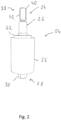
- the connection assembly 22 can be made in accordance with the principles of the present invention in two ways below with reference to Fig. 2 to 4 connection units 24 described in detail include.
- Each of the connection units 24 is electrically conductively connected to one of the two connection ends of the heating conductor 20 and provides the possibility of establishing a connection to a respective electrical supply line outside the exhaust gas routing component.
- connection unit 24 shown comprises, as a central component, a connection element 26 made, for example, of steel material and therefore electrically conductive.
- the connection element 26, which is preferably designed in one piece, has an internal connection area 30 at a first longitudinal end 28 of the connection element 26 with respect to a connection element longitudinal axis L.
- the inner connection area 30 can, for example, include a heating conductor receiving opening 32 and can be slotted, for example with two grooves 34.
- a connection end 36 of the heating conductor 20 is inserted into the heating conductor receiving opening 32.
- the connection element 26 can then be squeezed together, i.e. compressed, in its inner connection area 30, whereby the connection end 36 of the heating conductor 20 is firmly anchored to the connection element 26.
- this fixed connection can be made by material connection, such as. B. welding or soldering or gluing.
- the connecting element 26 has an external connection area 40.
- the external connection area 40 can, for example, be constructed with an external thread 42, onto which a nut that creates a fixed connection of an electrical supply line can be screwed.
- connection element 26 has an insulating arrangement support area, generally designated 44.
- the connection element 26 has two holding sections 46, 48 which widen axially towards one another or away from a closer longitudinal end 28, 38 with respect to the connection element longitudinal axis L.
- the two holding sections 46, 48 are designed with a conical outer circumferential contour and directly adjoin one another in their end regions 50, 52 with a maximum external dimension.
- a cylindrical section of the connecting element 26 could be positioned, i.e. a Section in which the connecting element 26 has an approximately constant radial dimension.
- the carrier arrangement 54 comprises a bush-like or sleeve-like first carrier element 56 made of metal material, for example steel material, which is inserted into an opening 58 of the exhaust gas guide component 14 and is secured to it in a stable and gas-tight manner by a weld seam 60.
- the carrier arrangement 54 further comprises a second bushing or sleeve-like carrier element 62, which is inserted into the end of the first carrier element 56 lying outside the exhaust gas guide component 14 and is connected to it by threaded engagement.
- the first carrier element 56 essentially has an internal thread 64 in its length region positioned outside the exhaust gas guide component 14, while the second carrier element 62 can be formed with an external thread 66 in its length region that is to be positioned so that it engages with the first carrier element 56.
- the first carrier element 56 has a radially expanding first support section 68.
- the first support section 68 can be shaped complementary to the first holding section 56, that is to say, for example, it can be designed to widen conically at least in the larger part of its longitudinal extent. In the assembled state, the first support section 68 essentially surrounds the first holding section 46.
- the second carrier element 62 has a second support section 70 in adaptation to the second holding section 48. This is according to the shape of the second holding section 48 is designed to expand conically and radially and surrounds the second holding section 48.
- an insulating arrangement generally designated 72 is provided. This includes a first insulating sleeve 74 in association with the first holding section 46 or the first support section 68 and a second insulating sleeve 76 in association with the second support section 48 or the second holding section 70.
- the two insulating sleeves 74, 76 are designed to expand radially towards one another in their inner peripheral areas and their outer peripheral areas, in particular also conically widening radially.
- the first insulating sleeve 74 can, for example, have an approximately cylindrical end section in its end region close to the first longitudinal end 28 of the connecting element 26, which surrounds the first longitudinal end 28 adjoining the first holding section 46, which can equally have, for example, a cylindrical outer peripheral contour, and on the outside of a corresponding cylindrically shaped axial end region of the first support section 68 is surrounded.
- the connecting element 26 is supported on the one hand radially with respect to the first carrier element 56 and the second carrier element 62, and is due to the shape of the two holding sections which widen radially towards one another 46, 68 and the complementary shape of the two support sections 68, 70 are also held in a form-fitting manner on the support arrangement 54 in the axial direction.
- the two insulating sleeves 74, 76 on the inner peripheral region is adapted to the shape of the two holding sections 46, 48 and on the outer peripheral region is adapted to the shape of the two support sections 68, 70
- the two insulating sleeves 74 made, for example, of ceramic material or mica material , 76 not only provides electrical insulation of the connection element 26 with respect to the carrier arrangement 54, but also realizes it due to the exact Fit also provides a gas-tight connection between the connecting element 26 and the carrier arrangement 54.
- the stable holder is provided or supported in particular by the fact that after the connection element 26 has been inserted with the first insulating sleeve 74 temporarily stored in the first carrier element 56 and the second insulating sleeve 76 has been applied to the second holding section 48, the second carrier element 62 is pushed onto the connection element 26 and is screwed into the first support element 56. The second carrier element 62 moves axially towards the inner connection region 30 of the connection element 26 and thus clamps the connection element 26 in a form-fitting, stable manner into the carrier arrangement 54. After this state has been achieved, the second carrier element 26 can be secured, for example, by material connection, such as. B. gluing or welding, can be connected to the first support element 56 in order to avoid loosening of this condition.
- material connection such as. B. gluing or welding
Landscapes
- Engineering & Computer Science (AREA)
- Chemical & Material Sciences (AREA)
- Combustion & Propulsion (AREA)
- Mechanical Engineering (AREA)
- General Engineering & Computer Science (AREA)
- Chemical Kinetics & Catalysis (AREA)
- Health & Medical Sciences (AREA)
- Toxicology (AREA)
- Exhaust Gas After Treatment (AREA)
- Exhaust Silencers (AREA)
Description
- Die die vorliegende Erfindung betrifft eine Anschlusseinheit für einen Abgasheizer in einer Abgasanlage einer Brennkraftmaschine.
- Aus der nachveröffentlichten deutschen Patentanmeldung
DE 10 2019 131 556 ist ein in einer rohrartigen Abgasführungskomponente einer Abgasanlage angeordneter Abgasheizer bekannt. Der Abgasheizer umfasst einen in der Abgasführungskomponente getragenen, plattenartigen Träger und an einer Seite des plattenartigen Trägers einen spiralartig gewundenen Heizleiter. Um den Heizleiter mit elektrischer Energie zu versorgen, müssen die beiden Anschlussenden des Heizleiters an jeweilige elektrische Versorgungsleitungen angeschlossen werden. Aus derEP 0 716 558 A2 ist eine Anschlusseinheit gemäß dem Oberbegriff des Anspruchs 1 bekannt, bei welcher ein Anschlusselement an einem an einer Abgasanlage festzulegenden ersten Trägerelement einer Trägeranordnung in beiden axialen Richtungen bezogen auf seine Längsachse elektrisch isoliert abgestützt ist und an einem an dem ersten Trägerelement festgelegten zweiten Trägerelement ein mit einem Außenanschlussbereich des Anschlusselements elektrisch leitend zu verbindendes Kabel getragen ist. - Es ist die Aufgabe der vorliegenden Erfindung, eine Anschlusseinheit für einen Abgasheizer in einer Abgasanlage einer Brennkraftmaschine vorzusehen, mit welcher in einfacher und zuverlässiger Weise eine elektrische Verbindung mit einem im Inneren einer Abgasführungskomponente einer Abgasanlage angeordneten Heizleiter des Abgasheizers hergestellt werden kann.
- Erfindungsgemäß wird diese Aufgabe gelöst durch eine Anschlusseinheit für einen Abgasheizer in einer Abgasanlage einer Brennkraftmaschine gemäß Anspruch 1.
- Mit einer derartigen Anschlusseinheit wird bei einfachem Aufbau die Möglichkeit geschaffen, einen Heizleiter im Inneren einer Abgasführungskomponente elektrisch zu kontaktieren, gleichzeitig jedoch diesen bzw. das Anschlusselement elektrisch bezüglich der im Allgemeinen aus Blechmaterial aufgebauten Abgasführungskomponente zu isolieren und eine gasdichte Verbindung zwischen dem Anschlusselement und der Abgasführungskomponente herzustellen.
- Um einerseits den elektrischen Anschluss an einen Heizleiter und andererseits den elektrischen Anschluss an eine außerhalb der Abgasanlage verlaufende Versorgungsleitung in einfacher Weise realisieren zu können, wird vorgeschlagen, dass der Innenanschlussbereich an einem ersten Längsende des Abschlusselements vorgesehen ist und der Außenanschlussbereich an einem zweiten Längsende des Abschlusselements vorgesehen ist, oder/und dass der Außenanschlussbereich ein Außengewinde umfasst, oder/und dass der Innenanschlussbereich eine Heizleiteraufnahmeöffnung umfasst.
- Für eine sowohl hinsichtlich der zu erreichenden elektrischen Isolierung, als auch hinsichtlich der zu erreichen gasdichten Verbindung vorteilhafte Ausgestaltung umfasst das Anschlusselement zwischen dem Innenanschlussbereich und dem Außenanschlussbereich einen vermittels der Isolieranordnung an der Trägeranordnung gehaltenen Isolieranordnung-Abstützbereich.
- Dabei wird eine stabile Haltewechselwirkung dadurch erreicht, dass der Isolieranordnung-Abstützbereich einen in Richtung von dem Innenanschlussbereich weg auf den Außenanschlussbereich zu sich radial erweiternden ersten Halteabschnitt und einen in Richtung von dem Außenanschlussbereich weg auf den ersten Halteabschnitt zu sich radial erweiternden zweiten Halteabschnitt umfasst.
- Für eine in der Längsrichtung des Anschlusselements kompakte Bauart kann vorgesehen sein, dass der erste Halteabschnitt und der zweite Halteabschnitt in ihren axialen Endbereichen mit maximaler Radialabmessung aneinander anschließen, oder/und dass der erste Halteabschnitt oder/und der zweite Halteabschnitt sich im Wesentlichen konisch radial erweiternd ausgebildet ist.
- Die Isolieranordnung kann wenigstens eine das Anschlusselement umgebende Isolierhülse umfassen.
- In Anpassung an die für eine stabile Halterung vorgesehene, radial sich erweiternde Formgebung des Anschlusselements ist vorzugsweise die Isolieranordnung derart gestaltet, dass diese in Zuordnung zu dem ersten Halteabschnitt eine erste Isolierhülse umfasst und in Zuordnung zu dem zweiten Halteabschnitt eine zweite Isolierhülse umfasst.
- Um über die Isolieranordnung sowohl bezüglich des Anschlusselements, als auch bezüglich der Trägeranordnung eine stabile Haltewechselwirkung zu gewährleisten, kann die erste Isolierhülse an einem Innenumfangsbereich und einem Außenumfangsbereich sich in Richtung auf die zweite Isolierhülse zu radial erweiternd ausgebildet sein, und die zweite Isolierhülse kann an einem Innenumfangsbereich und einem Außenumfangsbereich sich in Richtung auf die erste Isolierhülse zu radial erweiternd ausgebildet sein.
- Dabei ist vorzugsweise in Anpassung an die Formgebung des Anschlusselements die erste Isolierhülse oder/und die zweite Isolierhülse an ihrem Innenumfangsbereich und ihrem Außenumfangsbereich sich im Wesentlichen konisch radial erweiternd ausgebildet.
- Wenn die wenigstens eine Isolierhülse mit Keramikmaterial oder Glimmer-Material aufgebaut ist, wird eine mechanisch stabile, elektrische isolierende und auch einen gasdichten Abschluss gewährleistende Verbindung zwischen dem Anschlusselement und der Trägeranordnung erreicht.
- Die Trägeranordnung umfasst ein an einer Abgasanlage festzulegendes erstes Trägerelement und ein das Anschlusselement zusammen mit dem ersten Trägerelement einspannendes zweites Trägerelement.
- In Anpassung an die radial sich erweiternde Formgebung des Anschlusselements umfasst das erste Trägerelement in Zuordnung zu dem ersten Halteabschnitt einen in Richtung auf das zweite Trägerelement zu sich radial erweiternden ersten Trageabschnitt, und das zweite Trägerelement umfasst in Zuordnung zu dem zweiten Halteabschnitt einen in Richtung auf das erste Trägerelement zu sich radial erweiternden zweiten Trageabschnitt. Insbesondere kann dabei vorgesehen sein, dass bei konischer Ausgestaltung der beiden Halteabschnitte des Anschlusselements der erste Trageabschnitt oder/und der zweite Trageabschnitt sich im Wesentlichen konisch radial erweiternd ausgebildet ist.
- Dabei kann vorgesehen sein, dass der erste Trageabschnitt den ersten Halteabschnitt unter Zwischenlagerung der ersten Isolierhülse umgibt, und dass der zweite Trageabschnitt den zweiten Halteabschnitt unter Zwischenlagerung der zweiten Isolierhülse umgibt.
- Für eine stabile Halterung des Anschlusselements zwischen den beiden Trägerelementen wird vorgeschlagen, dass das erste Trägerelement mit dem zweiten Trägerelement axial bezüglich einander verlagerbar gekoppelt ist. Dies kann beispielsweise dadurch realisiert sein, dass das erste Trägerelement mit dem zweiten Trägerelement durch Gewindeeingriff gekoppelt ist. Durch Drehen der beiden Trägerelemente bezüglich einander, werden diese axial bezüglich einander verlagert, wodurch eine feste Einspannung des Anschlusselements unter Zwischenlagerung der Isolieranordnung erreicht wird.
- Die Erfindung betrifft ferner eine Abgasanlage für eine Brennkraftmaschine, umfassend eine Abgasführungskomponente, einen in der Abgasführungskomponente angeordneten Abgasheizer mit einem Heizleiter und in Zuordnung zu wenigstens einem, vorzugsweise jedem Anschlussende des Heizleiters eine erfindungsgemäß aufgebaute Anschlusseinheit.
- Die vorliegende Erfindung wird nachfolgend mit Bezug auf die beiliegenden Figuren detailliert beschrieben. Es zeigt:
- Fig. 1
- eine perspektivische Ansicht eines in einer Abgasführungskomponente einer Abgasanlage angeordneten Abgasheizers;
- Fig. 2
- eine Seitenansicht einer Anschlusseinheit für einen Heizleiter eines Abgasheizers;
- Fig. 3
- eine Schnittansicht der in eine Abgasführungskomponente integrierten Anschlusseinheit der
Fig. 2 ; - Fig. 4
- eine Seitenansicht eines Anschlusselements der Anschlusseinheit der
Fig. 2 . - Die
Fig. 1 zeigt einen beispielsweise aus der nachveröffentlichten deutschen PatentanmeldungDE 10 2019 131 556 bekannten Abgasheizer 10. Der Abgasheizer 10 umfasst einen beispielsweise aus Blechmaterial aufgebauten scheibenartigen, beispielsweise konisch geformten Träger 12, der in eine rohrartige Abgasführungskomponente 14 einer allgemein mit 16 bezeichneten Abgasanlage integriert ist. An einer Seite des Trägers 12 ist ein spiralartig gewundener Heizbereich 18 eines allgemein mit 20 bezeichneten Heizleiters vorgesehen. Der beispielsweise wenigstens bereichsweise nicht elektrisch isolierte, am Träger 12 gehaltene Heizbereich 18 des Heizleiters 20 erwärmt sich bei elektrischer Bestromung und erwärmt dadurch das beispielsweise in Richtung auf eine Katalysatoranordnung oder eine sonstige Abgasbehandlungseinheit zu strömende Abgas. - Um den Heizleiter 20 mit elektrischer Energie zu versorgen, ist bei dem in
Fig. 1 dargestellten Aufbau einer Abgasanlage eine prinzipartig dargestellte Anschlussbaugruppe 22 vorgesehen. Die Anschlussbaugruppe 22 kann gemäß den Prinzipien der vorliegenden Erfindung zwei nachfolgend mit Bezug auf dieFig. 2 bis 4 detailliert beschriebene Anschlusseinheiten 24 umfassen. Jede der Anschlusseinheiten 24 ist mit einem der beiden Anschlussenden des Heizleiters 20 elektrisch leitend verbunden und stellt die Möglichkeit bereit, außerhalb der Abgasführungskomponente einen Anschluss an eine jeweilige elektrische Versorgungsleitung herzustellen. - Die in den
Fig. 2 bis 4 dargestellte Anschlusseinheit 24 umfasst als zentrales Bauteil ein beispielsweise aus Stahlmaterial und damit elektrisch leitend ausgebildetes Anschlusselement 26. Das vorzugsweise einstückig ausgebildete Anschlusselement 26 weist an einem ersten Längsende 28 des Anschlusselements 26 bezüglich einer Anschlusselement-Längsachse L einen Innenanschlussbereich 30 auf. Der Innenanschlussbereich 30 kann beispielsweise eine Heizleiteraufnahmeöffnung 32 umfassen und kann geschlitzt, also beispielsweise mit zwei Nuten 34 ausgebildet seine. Ein Anschlussende 36 des Heizleiters 20 wird in die Heizleiteraufnahmeöffnung 32 eingeschoben. Daraufhin kann das Anschlusselement 26 in seinem Innenanschlussbereich 30 zusammengequetscht, also komprimiert werden, wodurch das Anschlussende 36 des Heizleiters 20 fest am Anschlusselement 26 verankert wird. Alternativ oder zusätzlich kann diese feste Verbindung durch Materialschluss, wie z. B. Verschweißen oder Verlöten oder Verkleben, erfolgen. - An seinem in Richtung der Anschlusselement-Längsachse L zweiten Längsende 38 weist das Anschlusselement 26 einen Außenanschlussbereich 40 auf. Der Außenanschlussbereich 40 kann beispielsweise mit einem Außengewinde 42 aufgebaut sein, auf welches eine einen festen Anschluss einer elektrischen Versorgungsleitung realisierende Mutter aufgeschraubt werden kann.
- Zwischen dem Innenanschlussbereich 30 und dem Außenanschlussbereich 42 weist das Anschlusselement 26 einen allgemein mit 44 bezeichneten Isolieranordnung-Abstützbereich auf. Im Isolieranordnung-Abstützbereich 44 weist das Anschlusselement 26 zwei bezüglich der Anschlusselement-Längsachse L axial sich aufeinander zu bzw. von einem jeweils näher liegenden Längsende 28, 38 weg sich erweiternde Halteabschnitte 46, 48 auf. Beispielsweise sind die beiden Halteabschnitte 46, 48 mit konischer Außenumfangskontur ausgebildet und schließen in ihren Endbereichen 50, 52 mit maximaler Außenabmessung unmittelbar aneinander an. Alternativ könnte zwischen dem Endbereich 50 mit maximaler Außenabmessung des ersten Halteabschnitts 46 und dem Endbereich 52 mit maximaler Radialabmessung des zweiten Halteabschnitts 48 beispielsweise ein zylindrischer Abschnitt des Anschlusselements 26 positioniert sein, also ein Abschnitt, in welchem das Anschlusselement 26 eine näherungsweise konstante Radialabmessung aufweist.
- Zur Festlegung der Anschlusseinheit 24 an der abgasführenden Komponente 14 ist eine allgemein mit 54 bezeichnete Trägeranordnung vorgesehen. Die Trägeranordnung 54 umfasst ein buchsenartig oder hülsenartig ausgebildetes erstes Trägerelement 56 aus Metallmaterial, beispielsweise Stahlmaterial, das in eine Öffnung 58 der Abgasführungskomponente 14 eingesetzt ist und durch eine Schweißnaht 60 stabil und gasdicht an dieser festgelegt ist.
- Die Trägeranordnung 54 umfasst ferner ein zweites buchsen- oder hülsenartig ausgebildetes Trägerelement 62, welches in das außerhalb der Abgasführungskomponente 14 liegende Ende des ersten Trägerelements 56 eingesetzt und durch Gewindeeingriff mit diesem verbunden ist. Dazu weist das erste Trägerelement 56 im Wesentlichen in seinem außerhalb der Abgasführungskomponente 14 positionierten Längenbereich ein Innengewinde 64 auf, während das zweite Trägerelement 62 in seinem in das erste Trägerelement 56 eingreifend zu positionierenden Längenbereich mit einem Außengewinde 66 ausgebildet sein kann. Durch Einschrauben des zweiten Trägerelements 62 in das erste Trägerelement 56 wird die axiale Positionierung des zweiten Trägerelements 62 bezüglich des ersten Trägerelements 56 verändert.
- In Anpassung an die radial sich erweiternde Ausgestaltung des ersten Halteabschnitts 46 des Anschlusselements 26 weist das erste Trägerelement 56 einen radial sich erweiternden ersten Trageabschnitt 68 auf. Der erste Trageabschnitt 68 kann zum ersten Halteabschnitt 56 komplementär geformt sein, also beispielsweise sich zumindest im größeren Teil seiner Längserstreckung konisch erweiternd ausgebildet sein. Im Zusammenbauzustand umgibt der erste Trageabschnitt 68 im Wesentlichen den ersten Halteabschnitt 46.
- Das zweite Trägerelement 62 weist in Anpassung an den zweiten Halteabschnitt 48 einen zweiten Trageabschnitt 70 auf. Dieser ist entsprechend der Formgebung des zweiten Halteabschnitts 48 sich konisch radial erweiternd ausgebildet und umgibt den zweiten Halteabschnitt 48.
- Zur Herstellung einer gasdichten, elektrisch isolierenden Haltewechselwirkung zwischen dem Anschlusselement 26 und der Trägeranordnung 54 ist eine allgemein mit 72 bezeichnete Isolieranordnung vorgesehen. Diese umfasst in Zuordnung zum ersten Halteabschnitt 46 bzw. zum ersten Trageabschnitt 68 eine erste Isolierhülse 74 und in Zuordnung zum zweiten Trageabschnitt 48 bzw. zum zweiten Halteabschnitt 70 eine zweite Isolierhülse 76. Angepasst an die Formgebung der beiden Halteabschnitte 46, 48 bzw. der diese umgebenden Trageabschnitte 68, 70 sind die beiden Isolierhülsen 74, 76 in ihren Innenumfangsbereichen und ihren Außenumfangsbereichen aufeinander zu sich radial erweiternd ausgebildet, insbesondere auch sich konisch radial erweiternd. Die erste Isolierhülse 74 kann beispielsweise in ihrem dem ersten Längsende 28 des Anschlusselements 26 nahe liegenden Endbereich einen näherungsweise zylindrischen Endabschnitt aufweisen, der das an den ersten Halteabschnitt 46 anschließende erste Längsende 28, welches gleichermaßen beispielsweise eine zylindrische Außenumfangskontur aufweisen kann, umgibt und außen von einem entsprechend zylindrisch geformten axialen Endbereich des ersten Trageabschnitts 68 umgeben ist.
- Unter Zwischenlagerung der beiden Isolierhülsen 74, 76, welche in axialer Richtung näherungsweise konstante Wandungsstärken aufweisen können, ist das Anschlusselement 26 einerseits radial bezüglich des ersten Trägerelements 56 und des zweiten Trägerelements 62 abgestützt, und ist aufgrund der aufeinander zu sich radial erweiternden Formgebung der beiden Halteabschnitte 46, 68 und der komplementären Formgebung der beiden Trageabschnitte 68, 70 auch in axialer Richtung formschlüssig an der Trägeranordnung 54 gehalten. Da die Formgebung der beiden Isolierhülsen 74, 76 am Innenumfangsbereich an die Formgebung der beiden Halteabschnitte 46, 48 angepasst ist und am Außenumfangsbereich an die Formgebung der beiden Trageabschnitte 68, 70 angepasst ist, stellen die beiden beispielsweise aus Keramikmaterial oder Glimmer-Material aufgebauten Isolierhülsen 74, 76 nicht nur eine elektrische Isolierung des Anschlusselements 26 bezüglich der Trägeranordnung 54 bereit, sondern realisieren aufgrund der exakten Passung auch eine gasdichte Verbindung zwischen dem Anschlusselement 26 und der Trägeranordnung 54.
- Die stabile Halterung wird insbesondere dadurch herreicht oder unterstützt, dass nach dem Einsetzen des Anschlusselements 26 unter Zwischenlagerung der ersten Isolierhülse 74 in das erste Trägerelement 56 und dem Aufbringen der zweiten Isolierhülse 76 auf den zweiten Halteabschnitt 48 das zweite Trägerelement 62 auf das Anschlusselement 26 aufgeschoben und in das erste Trägerelement 56 eingeschraubt wird. Dabei bewegt sich das zweite Trägerelement 62 axial auf den Innenanschlussbereich 30 des Anschlusselements 26 zu und spannt somit das Anschlusselement 26 formschlüssig stabil in die Trägeranordnung 54 ein. Nach Erlangung dieses Zustandes kann das zweite Trägerelement 26 beispielsweise durch Materialschluss, wie z. B. Verkleben oder Verschweißen, mit dem ersten Trägerelement 56 verbunden werden, um ein Lösen dieses Zustandes zu vermeiden.
Claims (12)
- Anschlusseinheit für einen Abgasheizer in einer Abgasanlage einer Brennkraftmaschine, umfassend:- ein in Richtung einer Anschlusselement-Längsachse (L) langgestrecktes, elektrisch leitendes Anschlusselement (26) mit einem Innenanschlussbereich (30) zum Anschluss an einen Heizleiter (20) und einem Außenanschlussbereich (40) zum Anschluss an eine elektrische Versorgungsleitung,- eine das Anschlusselement (26) umgebende Trägeranordnung (54),- eine das Anschlusselement (26) bezüglich der Trägeranordnung (54) isolierende Isolieranordnung (72),wobei das Anschlusselement (26) zwischen dem Innenanschlussbereich (30) und dem Außenanschlussbereich (40) einen vermittels der Isolieranordnung (72) an der Trägeranordnung (54) gehaltenen Isolieranordnung-Abstützbereich (44) umfasst,wobei der Isolieranordnung-Abstützbereich (44) einen in Richtung von dem Innenanschlussbereich (30) weg auf den Außenanschlussbereich (40) zu sich radial erweiternden ersten Halteabschnitt (46) und einen in Richtung von dem Außenanschlussbereich (40) weg auf den ersten Halteabschnitt (46) zu sich radial erweiternden zweiten Halteabschnitt (48) umfasst,wobei die Trägeranordnung (54) ein an einer Abgasanlage (16) festzulegendes erstes Trägerelement (56) und ein zweites Trägerelement (62) umfasst, wobei das erste Trägerelement (56) in Zuordnung zu dem ersten Halteabschnitt (46) einen in Richtung auf das zweite Trägerelement (62) zu sich radial erweiternden ersten Trageabschnitt (68) umfasst,dadurch gekennzeichnet,dass das zweite Trägerelement (62) in Zuordnung zu dem zweiten Halteabschnitt (48) einen in Richtung auf das erste Trägerelement (56) zu sich radial erweiternden zweiten Trageabschnitt (70) umfasst, unddass das erste Trägerelement (56) zusammen mit dem zweiten Trägerelement (62) das Anschlusselement (26) einspannt.
- Anschlusseinheit nach Anspruch 1, dadurch gekennzeichnet, dass der Innenanschlussbereich (30) an einem ersten Längsende (28) des Abschlusselements (26) vorgesehen ist und der Außenanschlussbereich (40) an einem zweiten Längsende (38) des Abschlusselements (26) vorgesehen ist, oder/und dass der Außenanschlussbereich (40) ein Außengewinde (42) umfasst, oder/und dass der Innenanschlussbereich (30) eine Heizleiteraufnahmeöffnung (32) umfasst.
- Anschlusseinheit nach Anspruch 1 oder 2, dadurch gekennzeichnet, dass der erste Halteabschnitt (46) und der zweite Halteabschnitt (48) in ihren axialen Endbereichen mit maximaler Radialabmessung aneinander anschließen, oder/und dass der erste Halteabschnitt (46) oder/und der zweite Halteabschnitt (48) sich im Wesentlichen konisch radial erweiternd ausgebildet ist.
- Anschlusseinheit nach einem der vorangehenden Ansprüche, dadurch gekennzeichnet, dass die Isolieranordnung (72) wenigstens eine das Anschlusselement (26) umgebende Isolierhülse (74, 76) umfasst.
- Anschlusseinheit nach Anspruch 4, dadurch gekennzeichnet, dass die Isolieranordnung (72) in Zuordnung zu dem ersten Halteabschnitt (46) eine erste Isolierhülse (74) umfasst und in Zuordnung zu dem zweiten Halteabschnitt (48) eine zweite Isolierhülse (76) umfasst.
- Anschlusseinheit nach Anspruch 5, dadurch gekennzeichnet, dass die erste Isolierhülse (74) an einem Innenumfangsbereich und einem Außenumfangsbereich sich in Richtung auf die zweite Isolierhülse (76) zu radial erweiternd ausgebildet ist, und dass die zweite Isolierhülse (76) an einem Innenumfangsbereich und einem Außenumfangsbereich sich in Richtung auf die erste Isolierhülse (74) zu radial erweiternd ausgebildet ist.
- Anschlusseinheit nach Anspruch 6 und Anspruch 3, dadurch gekennzeichnet, dass die erste Isolierhülse (74) oder/und die zweite Isolierhülse (76) an ihrem Innenumfangsbereich und ihrem Außenumfangsbereich sich im Wesentlichen konisch radial erweiternd ausgebildet ist.
- Anschlusseinheit nach einem der Ansprüche 4-7, dadurch gekennzeichnet, dass die wenigstens eine Isolierhülse (74, 76) mit Keramikmaterial oder Glimmer-Material aufgebaut ist.
- Anschlusseinheit nach einem der vorangehenden Ansprüche, dadurch gekennzeichnet, dass der erste Trageabschnitt (68) oder/und der zweite Trageabschnitt (70) sich im Wesentlichen konisch radial erweiternd ausgebildet ist.
- Anschlusseinheit nach Anspruch 5, oder einem der Ansprüche 6-9, sofern auf Anspruch 5 rückbezogen, dadurch gekennzeichnet, dass der erste Trageabschnitt (68) den ersten Halteabschnitt (46) unter Zwischenlagerung der ersten Isolierhülse (74) umgibt, und dass der zweite Trageabschnitt (70) den zweiten Halteabschnitt (48) unter Zwischenlagerung der zweiten Isolierhülse (76) umgibt.
- Anschlusseinheit nach einem der vorangehenden Ansprüche, dadurch gekennzeichnet, dass das erste Trägerelement (56) mit dem zweiten Trägerelement (62) axial bezüglich einander verlagerbar gekoppelt ist, vorzugsweise wobei das erste Trägerelement (56) mit dem zweiten Trägerelement (62) durch Gewindeeingriff gekoppelt ist.
- Abgasanlage für eine Brennkraftmaschine, umfassend eine Abgasführungskomponente (14), einen in der Abgasführungskomponente (14) angeordneten Abgasheizer (10) mit einem Heizleiter (20) und in Zuordnung zu wenigstens einem, vorzugsweise jedem Anschlussende (36) des Heizleiters (20) eine Anschlusseinheit (24) nach einem der vorangehenden Ansprüche.
Applications Claiming Priority (1)
| Application Number | Priority Date | Filing Date | Title |
|---|---|---|---|
| DE102020111428.1A DE102020111428A1 (de) | 2020-04-27 | 2020-04-27 | Anschlusseinheit für einen Abgasheizer |
Publications (2)
| Publication Number | Publication Date |
|---|---|
| EP3904647A1 EP3904647A1 (de) | 2021-11-03 |
| EP3904647B1 true EP3904647B1 (de) | 2024-02-14 |
Family
ID=75203093
Family Applications (1)
| Application Number | Title | Priority Date | Filing Date |
|---|---|---|---|
| EP21164439.8A Active EP3904647B1 (de) | 2020-04-27 | 2021-03-24 | Anschlusseinheit für einen abgasheizer |
Country Status (4)
| Country | Link |
|---|---|
| US (1) | US11486286B2 (de) |
| EP (1) | EP3904647B1 (de) |
| CN (1) | CN113644491B (de) |
| DE (1) | DE102020111428A1 (de) |
Families Citing this family (6)
| Publication number | Priority date | Publication date | Assignee | Title |
|---|---|---|---|---|
| FR3108677B1 (fr) * | 2020-03-30 | 2022-05-27 | Faurecia Systemes Dechappement | Dispositif de chauffage de gaz d’échappement, ligne d’échappement et véhicule associés |
| DE102021116420A1 (de) * | 2021-06-25 | 2022-12-29 | Purem GmbH | Verbindungsanordnung |
| CA3228841A1 (en) * | 2021-08-13 | 2023-02-16 | Saban Akyildiz | Exhaust system and components thereof |
| DE102022105603A1 (de) * | 2022-03-10 | 2023-09-14 | Purem GmbH | Abgasbehandlungsanordnung |
| FR3133949B1 (fr) * | 2022-03-22 | 2024-07-26 | Faurecia Systemes Dechappement | Connecteur électrique |
| DE102022207488A1 (de) * | 2022-07-21 | 2024-02-01 | Vitesco Technologies GmbH | Segmentierte elektrische Durchführung |
Family Cites Families (20)
| Publication number | Priority date | Publication date | Assignee | Title |
|---|---|---|---|---|
| JP2990797B2 (ja) * | 1990-11-30 | 1999-12-13 | 株式会社デンソー | ハニカムヒータ |
| JP3305505B2 (ja) * | 1994-07-29 | 2002-07-22 | 日本碍子株式会社 | 電極構造 |
| US5571485A (en) * | 1994-07-29 | 1996-11-05 | W. R. Grace & Co.-Conn. | Combined electrically heatable converter body |
| JP3078736B2 (ja) * | 1994-12-07 | 2000-08-21 | 日本碍子株式会社 | 電極構造および通電発熱式ヒーター |
| JP3494498B2 (ja) * | 1995-04-17 | 2004-02-09 | 日本碍子株式会社 | 電極構造および通電発熱式ヒーター |
| JPH11257058A (ja) * | 1998-03-12 | 1999-09-21 | Honda Motor Co Ltd | 排気ガス浄化触媒コンバータ加熱装置 |
| GB0301164D0 (en) * | 2003-01-18 | 2003-02-19 | Ceramaspeed Ltd | Temperature-responsive device |
| GB0316627D0 (en) * | 2003-07-16 | 2003-08-20 | Ceramaspeed Ltd | Radiant electric heater |
| DE102009005481B3 (de) * | 2009-01-21 | 2010-04-08 | Bleckmann Gmbh & Co. Kg | Verbindungselement für Heizwendel für Rohrheizkörper sowie Herstellungsverfahren hierfür |
| RU2595463C2 (ru) * | 2012-01-13 | 2016-08-27 | Эмитек Гезельшафт Фюр Эмиссионстехнологи Мбх | Электрически обогреваемое сотовое тело с несколькими электрически соединенными с соединительным штырьком слоями листового металла |
| DE102012005786A1 (de) * | 2012-03-21 | 2013-09-26 | Emitec Gesellschaft Für Emissionstechnologie Mbh | Verdrehsicherer elektrischer Anschluss, insbesondere für einen elektrisch beheizbaren Wabenkörper |
| ES2728255T3 (es) * | 2012-12-18 | 2019-10-23 | Watlow Electric Mfg | Aparato de calefacción de gas de escape mejorado y procedimiento de calefacción |
| DE102015003579A1 (de) * | 2015-03-19 | 2016-09-22 | Kathrein-Werke Kg | HF-Steckverbinder zur lotfreien Kontaktierung eines Koaxialkabels |
| DE202015103787U1 (de) * | 2015-07-17 | 2015-08-06 | Türk & Hillinger GmbH | Gaskanal mit beheizter poröser Metallstruktur |
| DE102015111689C5 (de) * | 2015-07-17 | 2022-09-01 | Türk & Hillinger GmbH | Elektrisch beheizbarer Katalysator und Verfahren zu dessen Herstellung |
| DE102015112286A1 (de) * | 2015-07-28 | 2017-02-02 | R. Stahl Schaltgeräte GmbH | Explosionsgeschützte Anordnung zur Bolzendurchführung und Verfahren zu deren Herstellung |
| DE102016209282B4 (de) * | 2016-05-30 | 2023-01-12 | Vitesco Technologies GmbH | Elektrischer Anschluss, insbesondere für einen elektrisch beheizbaren Wabenkörper |
| DE102016215806B4 (de) * | 2016-08-23 | 2024-01-04 | Volkswagen Aktiengesellschaft | Rückenlehnenanordnung für ein Kraftfahrzeug sowie Kraftfahrzeug |
| JP2020169614A (ja) * | 2019-04-04 | 2020-10-15 | 日本特殊陶業株式会社 | 排気ガス加熱装置 |
| DE102019131556A1 (de) | 2019-11-22 | 2021-05-27 | Eberspächer Exhaust Technology GmbH | Abgasheizer |
-
2020
- 2020-04-27 DE DE102020111428.1A patent/DE102020111428A1/de active Pending
-
2021
- 2021-03-24 EP EP21164439.8A patent/EP3904647B1/de active Active
- 2021-04-27 US US17/241,423 patent/US11486286B2/en active Active
- 2021-04-27 CN CN202110457144.XA patent/CN113644491B/zh active Active
Also Published As
| Publication number | Publication date |
|---|---|
| US20210332728A1 (en) | 2021-10-28 |
| CN113644491A (zh) | 2021-11-12 |
| DE102020111428A1 (de) | 2021-10-28 |
| CN113644491B (zh) | 2024-04-12 |
| EP3904647A1 (de) | 2021-11-03 |
| US11486286B2 (en) | 2022-11-01 |
Similar Documents
| Publication | Publication Date | Title |
|---|---|---|
| EP3904647B1 (de) | Anschlusseinheit für einen abgasheizer | |
| EP3825528A1 (de) | Abgasheizer | |
| EP3905845B1 (de) | Anschlusseinheit zum anschliessen einer elektrischen versorgungsleitung an ein anschlusselement einer beheizbaren abgasanlage | |
| WO2018046994A1 (de) | Elektrisch leifähiges kontaktelement für einen elektrischen steckverbinder | |
| DE102019121382A1 (de) | Abgasbehandlungseinrichtung und Fahrzeug | |
| EP2360804B1 (de) | Anordnung zum Verbinden von zwei Energiekabeln | |
| CH685403A5 (de) | Formteil aus thermoplastischem Material. | |
| DE102020110869A1 (de) | Abgasheizer | |
| EP4174295B1 (de) | Anschlussstift | |
| EP4141229B1 (de) | Abgasheizer und verfahren zur herstellung eines abgasheizers | |
| EP0693805B1 (de) | Anschlusselement für eine elektrische und mechanische Verbindung mit drehbeweglichen Anschlüssen an ein Schutzschlauchsystem für elektrische Leitungen | |
| DE102022111864B4 (de) | Heizvorrichtung | |
| EP3574509B1 (de) | Vorrichtung zum verbinden von abschirmungsrohren eines hochspannungsgeräts | |
| DE2703406B2 (de) | Verbindungsanordnung für koaxiale Leitungen | |
| DE102020116831A1 (de) | An einem langgestreckten leitfähigen Element angebrachter elektrischer Verbinder, insbesondere für eine Abgasreinigungsvorrichtung | |
| EP4144965A1 (de) | Abgasheizer | |
| EP4198273B1 (de) | Abgasheizer | |
| EP4381180B1 (de) | Segmentierte elektrische durchführung | |
| EP3907383A1 (de) | Abgasheizer für eine abgasanlage einer brennkraftmaschine | |
| EP4108891B1 (de) | Abgasheizanordnung mit einer verbindungsanordnung | |
| DE19516760A1 (de) | Verfahren zum elektrisch leitenden Verbinden von zwei elektrischen Leitungen | |
| EP4242434B1 (de) | Abgasbehandlungsanordnung | |
| EP1389807B1 (de) | Vorrichtung zum elektrisch leitenden Kontaktieren | |
| DE2410593B2 (de) | Elektrische rohrverbindungsklemme, insbesondere fuer grosse rohrdurchmesser | |
| DE102022111866A1 (de) | Heizvorrichtung |
Legal Events
| Date | Code | Title | Description |
|---|---|---|---|
| PUAI | Public reference made under article 153(3) epc to a published international application that has entered the european phase |
Free format text: ORIGINAL CODE: 0009012 |
|
| STAA | Information on the status of an ep patent application or granted ep patent |
Free format text: STATUS: THE APPLICATION HAS BEEN PUBLISHED |
|
| AK | Designated contracting states |
Kind code of ref document: A1 Designated state(s): AL AT BE BG CH CY CZ DE DK EE ES FI FR GB GR HR HU IE IS IT LI LT LU LV MC MK MT NL NO PL PT RO RS SE SI SK SM TR |
|
| B565 | Issuance of search results under rule 164(2) epc |
Effective date: 20210917 |
|
| STAA | Information on the status of an ep patent application or granted ep patent |
Free format text: STATUS: REQUEST FOR EXAMINATION WAS MADE |
|
| 17P | Request for examination filed |
Effective date: 20220210 |
|
| RBV | Designated contracting states (corrected) |
Designated state(s): AL AT BE BG CH CY CZ DE DK EE ES FI FR GB GR HR HU IE IS IT LI LT LU LV MC MK MT NL NO PL PT RO RS SE SI SK SM TR |
|
| STAA | Information on the status of an ep patent application or granted ep patent |
Free format text: STATUS: EXAMINATION IS IN PROGRESS |
|
| 17Q | First examination report despatched |
Effective date: 20220603 |
|
| GRAP | Despatch of communication of intention to grant a patent |
Free format text: ORIGINAL CODE: EPIDOSNIGR1 |
|
| STAA | Information on the status of an ep patent application or granted ep patent |
Free format text: STATUS: GRANT OF PATENT IS INTENDED |
|
| INTG | Intention to grant announced |
Effective date: 20231123 |
|
| GRAS | Grant fee paid |
Free format text: ORIGINAL CODE: EPIDOSNIGR3 |
|
| GRAA | (expected) grant |
Free format text: ORIGINAL CODE: 0009210 |
|
| STAA | Information on the status of an ep patent application or granted ep patent |
Free format text: STATUS: THE PATENT HAS BEEN GRANTED |
|
| AK | Designated contracting states |
Kind code of ref document: B1 Designated state(s): AL AT BE BG CH CY CZ DE DK EE ES FI FR GB GR HR HU IE IS IT LI LT LU LV MC MK MT NL NO PL PT RO RS SE SI SK SM TR |
|
| REG | Reference to a national code |
Ref country code: GB Ref legal event code: FG4D Free format text: NOT ENGLISH |
|
| REG | Reference to a national code |
Ref country code: CH Ref legal event code: EP |
|
| REG | Reference to a national code |
Ref country code: DE Ref legal event code: R096 Ref document number: 502021002655 Country of ref document: DE |
|
| REG | Reference to a national code |
Ref country code: IE Ref legal event code: FG4D Free format text: LANGUAGE OF EP DOCUMENT: GERMAN |
|
| REG | Reference to a national code |
Ref country code: LT Ref legal event code: MG9D |
|
| REG | Reference to a national code |
Ref country code: NL Ref legal event code: MP Effective date: 20240214 |
|
| PG25 | Lapsed in a contracting state [announced via postgrant information from national office to epo] |
Ref country code: IS Free format text: LAPSE BECAUSE OF FAILURE TO SUBMIT A TRANSLATION OF THE DESCRIPTION OR TO PAY THE FEE WITHIN THE PRESCRIBED TIME-LIMIT Effective date: 20240614 |
|
| PG25 | Lapsed in a contracting state [announced via postgrant information from national office to epo] |
Ref country code: LT Free format text: LAPSE BECAUSE OF FAILURE TO SUBMIT A TRANSLATION OF THE DESCRIPTION OR TO PAY THE FEE WITHIN THE PRESCRIBED TIME-LIMIT Effective date: 20240214 |
|
| PG25 | Lapsed in a contracting state [announced via postgrant information from national office to epo] |
Ref country code: GR Free format text: LAPSE BECAUSE OF FAILURE TO SUBMIT A TRANSLATION OF THE DESCRIPTION OR TO PAY THE FEE WITHIN THE PRESCRIBED TIME-LIMIT Effective date: 20240515 |
|
| PG25 | Lapsed in a contracting state [announced via postgrant information from national office to epo] |
Ref country code: NL Free format text: LAPSE BECAUSE OF FAILURE TO SUBMIT A TRANSLATION OF THE DESCRIPTION OR TO PAY THE FEE WITHIN THE PRESCRIBED TIME-LIMIT Effective date: 20240214 Ref country code: RS Free format text: LAPSE BECAUSE OF FAILURE TO SUBMIT A TRANSLATION OF THE DESCRIPTION OR TO PAY THE FEE WITHIN THE PRESCRIBED TIME-LIMIT Effective date: 20240514 Ref country code: HR Free format text: LAPSE BECAUSE OF FAILURE TO SUBMIT A TRANSLATION OF THE DESCRIPTION OR TO PAY THE FEE WITHIN THE PRESCRIBED TIME-LIMIT Effective date: 20240214 |
|
| PG25 | Lapsed in a contracting state [announced via postgrant information from national office to epo] |
Ref country code: ES Free format text: LAPSE BECAUSE OF FAILURE TO SUBMIT A TRANSLATION OF THE DESCRIPTION OR TO PAY THE FEE WITHIN THE PRESCRIBED TIME-LIMIT Effective date: 20240214 |
|
| PG25 | Lapsed in a contracting state [announced via postgrant information from national office to epo] |
Ref country code: RS Free format text: LAPSE BECAUSE OF FAILURE TO SUBMIT A TRANSLATION OF THE DESCRIPTION OR TO PAY THE FEE WITHIN THE PRESCRIBED TIME-LIMIT Effective date: 20240514 Ref country code: NO Free format text: LAPSE BECAUSE OF FAILURE TO SUBMIT A TRANSLATION OF THE DESCRIPTION OR TO PAY THE FEE WITHIN THE PRESCRIBED TIME-LIMIT Effective date: 20240514 Ref country code: NL Free format text: LAPSE BECAUSE OF FAILURE TO SUBMIT A TRANSLATION OF THE DESCRIPTION OR TO PAY THE FEE WITHIN THE PRESCRIBED TIME-LIMIT Effective date: 20240214 Ref country code: LT Free format text: LAPSE BECAUSE OF FAILURE TO SUBMIT A TRANSLATION OF THE DESCRIPTION OR TO PAY THE FEE WITHIN THE PRESCRIBED TIME-LIMIT Effective date: 20240214 Ref country code: IS Free format text: LAPSE BECAUSE OF FAILURE TO SUBMIT A TRANSLATION OF THE DESCRIPTION OR TO PAY THE FEE WITHIN THE PRESCRIBED TIME-LIMIT Effective date: 20240614 Ref country code: HR Free format text: LAPSE BECAUSE OF FAILURE TO SUBMIT A TRANSLATION OF THE DESCRIPTION OR TO PAY THE FEE WITHIN THE PRESCRIBED TIME-LIMIT Effective date: 20240214 Ref country code: GR Free format text: LAPSE BECAUSE OF FAILURE TO SUBMIT A TRANSLATION OF THE DESCRIPTION OR TO PAY THE FEE WITHIN THE PRESCRIBED TIME-LIMIT Effective date: 20240515 Ref country code: FI Free format text: LAPSE BECAUSE OF FAILURE TO SUBMIT A TRANSLATION OF THE DESCRIPTION OR TO PAY THE FEE WITHIN THE PRESCRIBED TIME-LIMIT Effective date: 20240214 Ref country code: ES Free format text: LAPSE BECAUSE OF FAILURE TO SUBMIT A TRANSLATION OF THE DESCRIPTION OR TO PAY THE FEE WITHIN THE PRESCRIBED TIME-LIMIT Effective date: 20240214 Ref country code: BG Free format text: LAPSE BECAUSE OF FAILURE TO SUBMIT A TRANSLATION OF THE DESCRIPTION OR TO PAY THE FEE WITHIN THE PRESCRIBED TIME-LIMIT Effective date: 20240214 |
|
| PG25 | Lapsed in a contracting state [announced via postgrant information from national office to epo] |
Ref country code: PT Free format text: LAPSE BECAUSE OF FAILURE TO SUBMIT A TRANSLATION OF THE DESCRIPTION OR TO PAY THE FEE WITHIN THE PRESCRIBED TIME-LIMIT Effective date: 20240614 Ref country code: PL Free format text: LAPSE BECAUSE OF FAILURE TO SUBMIT A TRANSLATION OF THE DESCRIPTION OR TO PAY THE FEE WITHIN THE PRESCRIBED TIME-LIMIT Effective date: 20240214 |
|
| PG25 | Lapsed in a contracting state [announced via postgrant information from national office to epo] |
Ref country code: SE Free format text: LAPSE BECAUSE OF FAILURE TO SUBMIT A TRANSLATION OF THE DESCRIPTION OR TO PAY THE FEE WITHIN THE PRESCRIBED TIME-LIMIT Effective date: 20240214 Ref country code: PT Free format text: LAPSE BECAUSE OF FAILURE TO SUBMIT A TRANSLATION OF THE DESCRIPTION OR TO PAY THE FEE WITHIN THE PRESCRIBED TIME-LIMIT Effective date: 20240614 Ref country code: PL Free format text: LAPSE BECAUSE OF FAILURE TO SUBMIT A TRANSLATION OF THE DESCRIPTION OR TO PAY THE FEE WITHIN THE PRESCRIBED TIME-LIMIT Effective date: 20240214 Ref country code: LV Free format text: LAPSE BECAUSE OF FAILURE TO SUBMIT A TRANSLATION OF THE DESCRIPTION OR TO PAY THE FEE WITHIN THE PRESCRIBED TIME-LIMIT Effective date: 20240214 |
|
| PG25 | Lapsed in a contracting state [announced via postgrant information from national office to epo] |
Ref country code: DK Free format text: LAPSE BECAUSE OF FAILURE TO SUBMIT A TRANSLATION OF THE DESCRIPTION OR TO PAY THE FEE WITHIN THE PRESCRIBED TIME-LIMIT Effective date: 20240214 |
|
| PG25 | Lapsed in a contracting state [announced via postgrant information from national office to epo] |
Ref country code: SM Free format text: LAPSE BECAUSE OF FAILURE TO SUBMIT A TRANSLATION OF THE DESCRIPTION OR TO PAY THE FEE WITHIN THE PRESCRIBED TIME-LIMIT Effective date: 20240214 |
|
| PG25 | Lapsed in a contracting state [announced via postgrant information from national office to epo] |
Ref country code: CZ Free format text: LAPSE BECAUSE OF FAILURE TO SUBMIT A TRANSLATION OF THE DESCRIPTION OR TO PAY THE FEE WITHIN THE PRESCRIBED TIME-LIMIT Effective date: 20240214 Ref country code: EE Free format text: LAPSE BECAUSE OF FAILURE TO SUBMIT A TRANSLATION OF THE DESCRIPTION OR TO PAY THE FEE WITHIN THE PRESCRIBED TIME-LIMIT Effective date: 20240214 |
|
| PG25 | Lapsed in a contracting state [announced via postgrant information from national office to epo] |
Ref country code: SK Free format text: LAPSE BECAUSE OF FAILURE TO SUBMIT A TRANSLATION OF THE DESCRIPTION OR TO PAY THE FEE WITHIN THE PRESCRIBED TIME-LIMIT Effective date: 20240214 |
|
| PG25 | Lapsed in a contracting state [announced via postgrant information from national office to epo] |
Ref country code: SM Free format text: LAPSE BECAUSE OF FAILURE TO SUBMIT A TRANSLATION OF THE DESCRIPTION OR TO PAY THE FEE WITHIN THE PRESCRIBED TIME-LIMIT Effective date: 20240214 Ref country code: SK Free format text: LAPSE BECAUSE OF FAILURE TO SUBMIT A TRANSLATION OF THE DESCRIPTION OR TO PAY THE FEE WITHIN THE PRESCRIBED TIME-LIMIT Effective date: 20240214 Ref country code: RO Free format text: LAPSE BECAUSE OF FAILURE TO SUBMIT A TRANSLATION OF THE DESCRIPTION OR TO PAY THE FEE WITHIN THE PRESCRIBED TIME-LIMIT Effective date: 20240214 Ref country code: EE Free format text: LAPSE BECAUSE OF FAILURE TO SUBMIT A TRANSLATION OF THE DESCRIPTION OR TO PAY THE FEE WITHIN THE PRESCRIBED TIME-LIMIT Effective date: 20240214 Ref country code: DK Free format text: LAPSE BECAUSE OF FAILURE TO SUBMIT A TRANSLATION OF THE DESCRIPTION OR TO PAY THE FEE WITHIN THE PRESCRIBED TIME-LIMIT Effective date: 20240214 Ref country code: CZ Free format text: LAPSE BECAUSE OF FAILURE TO SUBMIT A TRANSLATION OF THE DESCRIPTION OR TO PAY THE FEE WITHIN THE PRESCRIBED TIME-LIMIT Effective date: 20240214 |
|
| REG | Reference to a national code |
Ref country code: CH Ref legal event code: PL |
|
| REG | Reference to a national code |
Ref country code: DE Ref legal event code: R097 Ref document number: 502021002655 Country of ref document: DE |
|
| PG25 | Lapsed in a contracting state [announced via postgrant information from national office to epo] |
Ref country code: LU Free format text: LAPSE BECAUSE OF NON-PAYMENT OF DUE FEES Effective date: 20240324 |
|
| PG25 | Lapsed in a contracting state [announced via postgrant information from national office to epo] |
Ref country code: MC Free format text: LAPSE BECAUSE OF FAILURE TO SUBMIT A TRANSLATION OF THE DESCRIPTION OR TO PAY THE FEE WITHIN THE PRESCRIBED TIME-LIMIT Effective date: 20240214 |
|
| PG25 | Lapsed in a contracting state [announced via postgrant information from national office to epo] |
Ref country code: MC Free format text: LAPSE BECAUSE OF FAILURE TO SUBMIT A TRANSLATION OF THE DESCRIPTION OR TO PAY THE FEE WITHIN THE PRESCRIBED TIME-LIMIT Effective date: 20240214 Ref country code: LU Free format text: LAPSE BECAUSE OF NON-PAYMENT OF DUE FEES Effective date: 20240324 |
|
| PG25 | Lapsed in a contracting state [announced via postgrant information from national office to epo] |
Ref country code: IT Free format text: LAPSE BECAUSE OF FAILURE TO SUBMIT A TRANSLATION OF THE DESCRIPTION OR TO PAY THE FEE WITHIN THE PRESCRIBED TIME-LIMIT Effective date: 20240214 |
|
| REG | Reference to a national code |
Ref country code: BE Ref legal event code: MM Effective date: 20240331 |
|
| PLBE | No opposition filed within time limit |
Free format text: ORIGINAL CODE: 0009261 |
|
| STAA | Information on the status of an ep patent application or granted ep patent |
Free format text: STATUS: NO OPPOSITION FILED WITHIN TIME LIMIT |
|
| PG25 | Lapsed in a contracting state [announced via postgrant information from national office to epo] |
Ref country code: IT Free format text: LAPSE BECAUSE OF FAILURE TO SUBMIT A TRANSLATION OF THE DESCRIPTION OR TO PAY THE FEE WITHIN THE PRESCRIBED TIME-LIMIT Effective date: 20240214 |
|
| PG25 | Lapsed in a contracting state [announced via postgrant information from national office to epo] |
Ref country code: BE Free format text: LAPSE BECAUSE OF NON-PAYMENT OF DUE FEES Effective date: 20240331 |
|
| 26N | No opposition filed |
Effective date: 20241115 |
|
| PG25 | Lapsed in a contracting state [announced via postgrant information from national office to epo] |
Ref country code: IE Free format text: LAPSE BECAUSE OF NON-PAYMENT OF DUE FEES Effective date: 20240324 |
|
| PG25 | Lapsed in a contracting state [announced via postgrant information from national office to epo] |
Ref country code: IE Free format text: LAPSE BECAUSE OF NON-PAYMENT OF DUE FEES Effective date: 20240324 Ref country code: BE Free format text: LAPSE BECAUSE OF NON-PAYMENT OF DUE FEES Effective date: 20240331 Ref country code: CH Free format text: LAPSE BECAUSE OF NON-PAYMENT OF DUE FEES Effective date: 20240331 |
|
| PG25 | Lapsed in a contracting state [announced via postgrant information from national office to epo] |
Ref country code: SI Free format text: LAPSE BECAUSE OF FAILURE TO SUBMIT A TRANSLATION OF THE DESCRIPTION OR TO PAY THE FEE WITHIN THE PRESCRIBED TIME-LIMIT Effective date: 20240214 |
|
| PGFP | Annual fee paid to national office [announced via postgrant information from national office to epo] |
Ref country code: AT Payment date: 20250417 Year of fee payment: 5 |
|
| PG25 | Lapsed in a contracting state [announced via postgrant information from national office to epo] |
Ref country code: CY Free format text: LAPSE BECAUSE OF FAILURE TO SUBMIT A TRANSLATION OF THE DESCRIPTION OR TO PAY THE FEE WITHIN THE PRESCRIBED TIME-LIMIT; INVALID AB INITIO Effective date: 20210324 |
|
| PG25 | Lapsed in a contracting state [announced via postgrant information from national office to epo] |
Ref country code: HU Free format text: LAPSE BECAUSE OF FAILURE TO SUBMIT A TRANSLATION OF THE DESCRIPTION OR TO PAY THE FEE WITHIN THE PRESCRIBED TIME-LIMIT; INVALID AB INITIO Effective date: 20210324 |
|
| PG25 | Lapsed in a contracting state [announced via postgrant information from national office to epo] |
Ref country code: TR Free format text: LAPSE BECAUSE OF FAILURE TO SUBMIT A TRANSLATION OF THE DESCRIPTION OR TO PAY THE FEE WITHIN THE PRESCRIBED TIME-LIMIT Effective date: 20240214 |
|
| PGFP | Annual fee paid to national office [announced via postgrant information from national office to epo] |
Ref country code: GB Payment date: 20260324 Year of fee payment: 6 |
|
| PGFP | Annual fee paid to national office [announced via postgrant information from national office to epo] |
Ref country code: DE Payment date: 20260320 Year of fee payment: 6 |
|
| PGFP | Annual fee paid to national office [announced via postgrant information from national office to epo] |
Ref country code: FR Payment date: 20260325 Year of fee payment: 6 |