EP3904306A1 - Multi-fiber light guide, device with a multi-fiber light guide and method for producing the same - Google Patents
Multi-fiber light guide, device with a multi-fiber light guide and method for producing the same Download PDFInfo
- Publication number
- EP3904306A1 EP3904306A1 EP20172235.2A EP20172235A EP3904306A1 EP 3904306 A1 EP3904306 A1 EP 3904306A1 EP 20172235 A EP20172235 A EP 20172235A EP 3904306 A1 EP3904306 A1 EP 3904306A1
- Authority
- EP
- European Patent Office
- Prior art keywords
- light guide
- glass
- fiber light
- cores
- fiber
- Prior art date
- Legal status (The legal status is an assumption and is not a legal conclusion. Google has not performed a legal analysis and makes no representation as to the accuracy of the status listed.)
- Granted
Links
Images


Classifications
-
- G—PHYSICS
- G02—OPTICS
- G02B—OPTICAL ELEMENTS, SYSTEMS OR APPARATUS
- G02B6/00—Light guides; Structural details of arrangements comprising light guides and other optical elements, e.g. couplings
- G02B6/02—Optical fibres with cladding with or without a coating
- G02B6/02395—Glass optical fibre with a protective coating, e.g. two layer polymer coating deposited directly on a silica cladding surface during fibre manufacture
-
- G—PHYSICS
- G02—OPTICS
- G02B—OPTICAL ELEMENTS, SYSTEMS OR APPARATUS
- G02B6/00—Light guides; Structural details of arrangements comprising light guides and other optical elements, e.g. couplings
- G02B6/04—Light guides; Structural details of arrangements comprising light guides and other optical elements, e.g. couplings formed by bundles of fibres
- G02B6/06—Light guides; Structural details of arrangements comprising light guides and other optical elements, e.g. couplings formed by bundles of fibres the relative position of the fibres being the same at both ends, e.g. for transporting images
- G02B6/08—Light guides; Structural details of arrangements comprising light guides and other optical elements, e.g. couplings formed by bundles of fibres the relative position of the fibres being the same at both ends, e.g. for transporting images with fibre bundle in form of plate
-
- A—HUMAN NECESSITIES
- A61—MEDICAL OR VETERINARY SCIENCE; HYGIENE
- A61B—DIAGNOSIS; SURGERY; IDENTIFICATION
- A61B5/00—Measuring for diagnostic purposes; Identification of persons
- A61B5/02—Detecting, measuring or recording for evaluating the cardiovascular system, e.g. pulse, heart rate, blood pressure or blood flow
- A61B5/024—Measuring pulse rate or heart rate
- A61B5/02416—Measuring pulse rate or heart rate using photoplethysmograph signals, e.g. generated by infrared radiation
- A61B5/02427—Details of sensor
-
- A—HUMAN NECESSITIES
- A61—MEDICAL OR VETERINARY SCIENCE; HYGIENE
- A61B—DIAGNOSIS; SURGERY; IDENTIFICATION
- A61B5/00—Measuring for diagnostic purposes; Identification of persons
- A61B5/02—Detecting, measuring or recording for evaluating the cardiovascular system, e.g. pulse, heart rate, blood pressure or blood flow
- A61B5/024—Measuring pulse rate or heart rate
- A61B5/02438—Measuring pulse rate or heart rate with portable devices, e.g. worn by the patient
-
- C—CHEMISTRY; METALLURGY
- C03—GLASS; MINERAL OR SLAG WOOL
- C03B—MANUFACTURE, SHAPING, OR SUPPLEMENTARY PROCESSES
- C03B37/00—Manufacture or treatment of flakes, fibres, or filaments from softened glass, minerals, or slags
- C03B37/01—Manufacture of glass fibres or filaments
- C03B37/012—Manufacture of preforms for drawing fibres or filaments
- C03B37/01205—Manufacture of preforms for drawing fibres or filaments starting from tubes, rods, fibres or filaments
-
- C—CHEMISTRY; METALLURGY
- C03—GLASS; MINERAL OR SLAG WOOL
- C03B—MANUFACTURE, SHAPING, OR SUPPLEMENTARY PROCESSES
- C03B37/00—Manufacture or treatment of flakes, fibres, or filaments from softened glass, minerals, or slags
- C03B37/01—Manufacture of glass fibres or filaments
- C03B37/012—Manufacture of preforms for drawing fibres or filaments
- C03B37/01205—Manufacture of preforms for drawing fibres or filaments starting from tubes, rods, fibres or filaments
- C03B37/01211—Manufacture of preforms for drawing fibres or filaments starting from tubes, rods, fibres or filaments by inserting one or more rods or tubes into a tube
- C03B37/01214—Manufacture of preforms for drawing fibres or filaments starting from tubes, rods, fibres or filaments by inserting one or more rods or tubes into a tube for making preforms of multifibres, fibre bundles other than multiple core preforms
-
- C—CHEMISTRY; METALLURGY
- C03—GLASS; MINERAL OR SLAG WOOL
- C03B—MANUFACTURE, SHAPING, OR SUPPLEMENTARY PROCESSES
- C03B37/00—Manufacture or treatment of flakes, fibres, or filaments from softened glass, minerals, or slags
- C03B37/01—Manufacture of glass fibres or filaments
- C03B37/02—Manufacture of glass fibres or filaments by drawing or extruding, e.g. direct drawing of molten glass from nozzles; Cooling fins therefor
- C03B37/025—Manufacture of glass fibres or filaments by drawing or extruding, e.g. direct drawing of molten glass from nozzles; Cooling fins therefor from reheated softened tubes, rods, fibres or filaments, e.g. drawing fibres from preforms
- C03B37/027—Fibres composed of different sorts of glass, e.g. glass optical fibres
-
- C—CHEMISTRY; METALLURGY
- C03—GLASS; MINERAL OR SLAG WOOL
- C03C—CHEMICAL COMPOSITION OF GLASSES, GLAZES OR VITREOUS ENAMELS; SURFACE TREATMENT OF GLASS; SURFACE TREATMENT OF FIBRES OR FILAMENTS MADE FROM GLASS, MINERALS OR SLAGS; JOINING GLASS TO GLASS OR OTHER MATERIALS
- C03C13/00—Fibre or filament compositions
- C03C13/04—Fibre optics, e.g. core and clad fibre compositions
-
- C—CHEMISTRY; METALLURGY
- C03—GLASS; MINERAL OR SLAG WOOL
- C03C—CHEMICAL COMPOSITION OF GLASSES, GLAZES OR VITREOUS ENAMELS; SURFACE TREATMENT OF GLASS; SURFACE TREATMENT OF FIBRES OR FILAMENTS MADE FROM GLASS, MINERALS OR SLAGS; JOINING GLASS TO GLASS OR OTHER MATERIALS
- C03C21/00—Treatment of glass, not in the form of fibres or filaments, by diffusing ions or metals in the surface
- C03C21/001—Treatment of glass, not in the form of fibres or filaments, by diffusing ions or metals in the surface in liquid phase, e.g. molten salts, solutions
- C03C21/002—Treatment of glass, not in the form of fibres or filaments, by diffusing ions or metals in the surface in liquid phase, e.g. molten salts, solutions to perform ion-exchange between alkali ions
-
- C—CHEMISTRY; METALLURGY
- C03—GLASS; MINERAL OR SLAG WOOL
- C03C—CHEMICAL COMPOSITION OF GLASSES, GLAZES OR VITREOUS ENAMELS; SURFACE TREATMENT OF GLASS; SURFACE TREATMENT OF FIBRES OR FILAMENTS MADE FROM GLASS, MINERALS OR SLAGS; JOINING GLASS TO GLASS OR OTHER MATERIALS
- C03C25/00—Surface treatment of fibres or filaments made from glass, minerals or slags
- C03C25/60—Surface treatment of fibres or filaments made from glass, minerals or slags by diffusing ions or metals into the surface
- C03C25/601—Surface treatment of fibres or filaments made from glass, minerals or slags by diffusing ions or metals into the surface in the liquid phase, e.g. using solutions or molten salts
- C03C25/602—Surface treatment of fibres or filaments made from glass, minerals or slags by diffusing ions or metals into the surface in the liquid phase, e.g. using solutions or molten salts to perform ion-exchange between alkali ions
-
- G—PHYSICS
- G01—MEASURING; TESTING
- G01J—MEASUREMENT OF INTENSITY, VELOCITY, SPECTRAL CONTENT, POLARISATION, PHASE OR PULSE CHARACTERISTICS OF INFRARED, VISIBLE OR ULTRAVIOLET LIGHT; COLORIMETRY; RADIATION PYROMETRY
- G01J1/00—Photometry, e.g. photographic exposure meter
- G01J1/02—Details
- G01J1/04—Optical or mechanical part supplementary adjustable parts
- G01J1/0407—Optical elements not provided otherwise, e.g. manifolds, windows, holograms, gratings
- G01J1/0425—Optical elements not provided otherwise, e.g. manifolds, windows, holograms, gratings using optical fibers
-
- C—CHEMISTRY; METALLURGY
- C03—GLASS; MINERAL OR SLAG WOOL
- C03B—MANUFACTURE, SHAPING, OR SUPPLEMENTARY PROCESSES
- C03B2201/00—Type of glass produced
- C03B2201/06—Doped silica-based glasses
- C03B2201/30—Doped silica-based glasses doped with metals, e.g. Ga, Sn, Sb, Pb or Bi
- C03B2201/50—Doped silica-based glasses doped with metals, e.g. Ga, Sn, Sb, Pb or Bi doped with alkali metals
-
- C—CHEMISTRY; METALLURGY
- C03—GLASS; MINERAL OR SLAG WOOL
- C03B—MANUFACTURE, SHAPING, OR SUPPLEMENTARY PROCESSES
- C03B2203/00—Fibre product details, e.g. structure, shape
- C03B2203/40—Multifibres or fibre bundles, e.g. for making image fibres
Definitions
- This disclosure generally concerns fiber optical light guides. Specifically, the disclosure relates to fiber optical devices with a multitude of merged light guiding fibers.
- US 2008/0069505 A1 discloses a pixel display covered with a fiber optical faceplate which is mounted in a distance to the pixels. Further, US 2006/0008220 A1 describes an optical low-pass filter using a fiber face plate.
- Fiber optical plates used in front of displays may serve to increase or decrease the viewing angle or generally to shift the image plane relative to the display.
- a faceplate the individual fibers are fused together so that the longitudinal direction of the fibers lies transverse to the faces of the faceplate.
- the fusing areas may provide weakening zones extending transversely through the plate.
- the glasses for fiber optical light guides are chosen because of their optical properties. Thus, suitable glasses may not necessarily be the strongest glasses in terms of mechanical stability. Thus, rigid multi-fiber light guides are prone to breakage upon mechanical stress, in particular by an impact or shock.
- this disclosure provides a multi-fiber light guide, comprising a multitude of light guiding fibers, each of the fibers comprising an elongated glass core.
- the cores are surrounded by a glass cladding so that the cladding with the cores form a rigid continuous glass element.
- the cores have a higher refractive index than the cladding so that light can be guided by total reflection along the glass cores.
- the glass element (9) of the multi-fiber light guide has two abutting faces), with the cores ending in both abutting faces, so that light can be guided along the cores from one abutting face to the other.
- the glasses of the cores and the cladding contain alkali ions.
- the alkali ions of the glasses are at least partly exchanged by alkali ions of a higher atomic number within an ion exchange layer at each of the abutting faces.
- the exchanged alkali ions within the ion exchange layer impart a compressive stress at the abutting faces.
- a multi fiber light guide is provided which has chemically strengthened abutting faces. It has been surprisingly found that a continuous layer with compressive stress can be formed at the abutting faces although the glasses of the cores and the cladding differ in their chemical composition.
- the glass element forming the multi-fiber light guide is a plate or disc., respectively.
- the abutting faces of the light guide are typically closer together than the longest lateral dimension of the glass element.
- the thickness of the disc or plate is smaller than the longest lateral dimension.
- the thickness of the disc defines the length of fibers
- the length of the light guiding fibers is smaller than the longest lateral dimension.
- a multi-fiber light guide of this type will in the following be referred to as a faceplate.
- this condition also hold for the shortest lateral dimension of the disc or plate.
- the thickness of the plate or the length of the fibers or cores is smaller than the shortest lateral dimension of the disc.
- the multi-fiber light guide has an elongated shape.
- the fiber length is greater than the largest lateral dimension of the glass element.
- the multi-fiber light guide a method for producing the same and devices including the light guide are hereinafter described in detail and with reference to the figures.
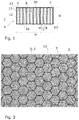
- Fig. 1 shows an example of a multi-fiber light guide 1 having a disc or plate like shape.
- the width w or its lateral dimension is generally larger than the thickness d or length of the light guide 1.
- the light guide 1 comprises a multitude of light guiding fibers 3.
- the fibers 3 are arranged side by side so that their longitudinal directions are generally parallel to each other.
- the fibers 3 comprise a core 5 embedded into a cladding 7.
- the glasses of core 5 and cladding 7 are fused together so that the cores 5 and the cladding 7 form a continuous rigid glass element 9.
- the individual fibers are of microscopic size to enable transfer of optical signals with high spatial resolution.
- the pitch or center-to center distance c of adjacent light guiding fibers 3 is from 2 ⁇ m to 500 ⁇ m, preferably at most 200 ⁇ m.
- the light guiding fibers 3 end in both opposing abutting faces 10, 11 of the glass element 9. This way, as the fibers 3 connect the abutting faces 10, 11, the fibers 3 guide light received at one of the abutting faces 10, 11 and emit the light at the respective opposed abutting face 11, 10.
- the interfaces between the cores 5 and the cladding 7 extend in transverse direction to the abutting faces 10, 11 and may constitute weakening zones.
- the abutting faces 10, 11 are subjected to an ion-exchange process so that ion-exchange layers 13 are formed at the surface of the abutting faces 10, 11.
- the glasses of both the cores 5 and the cladding 7 have compositions with alkali oxides.
- the alkali ions of the glasses are partly exchanged by heavier alkali ions having a larger ion radius. This way, the ions impart a compressive stress to the glass within the ion-exchange layers 13.
- the ion-exchange layer 13 is produced by fully immersing the glass element into a salt bath, the ion exchange occurs at the entire surface of the glass element 9.
- the ion-exchange layer 13 also extends along the outer circumferential surface or shell 12 which connects and extends between the two abutting faces 10, 11.
- Fig. 2 shows a photographic image of an abutting face 10, 11 of a multi-fiber light guide 1.
- the cores 5 may have a hexagonal cross section.
- the cores 5 may be arranged in a hexagonal pattern. These features can be advantageous in several respects. If an image of a pixel display is transferred from one abutting face to the opposed face, the hexagonal pattern may help to avoid moire patterns at the abutting face where the light exits. Further, the honeycomb-like structure of the interfaces between cores 5 and cladding may increase mechanical stability.
- the glass of the cladding 7 may be at least partially light absorbing. This is generally advantageous to reduce cross-talk or light leaching between the fibers 3.
- the glass of the cladding 7 is a black glass.
- the glass may also be partially absorbing as it is the case for colored glasses.
- the glass has a spectrally dependent and spectrally varying absorption.
- the glass may be brown, red or purple colored.
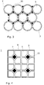
- FIG. 3 shows a stack of individual light guiding fibers 3 with light absorbing fibers 15 being located in interstices between the light guiding fibers 3.
- the fibers 3, 15 of the stack can be fused together to form a rigid rod.
- Multi-fiber light guides 1 can then be produced by cutting sections of desired dimensions from the rod.
- Fig. 4 shows an example of a multi-fiber light guide 1 with the fibers fused together to form a rigid continuous glass element 9.
- the cores 5 are arranged in a square pattern.
- a light absorbing fiber 15 is arranged at every second intersection of four cores 5 .
- Both the cores 5 and the light absorbing fibers 5 are surrounded by the cladding 7.
- the additional light absorbing fibers 15 within the rigid glass element 9 provide an extra-mural absorption to reduce cross talk or to block light which obliquely transits the multi-fiber light guide 1.
- the multi-fiber light guide 1 comprises three different glasses, i.e., the glass of the cores 5, the glass of the cladding 7 and the glass of the light absorbing fibers 15.
- the glass of the light absorbing fibers 15 may be similar to one of the other glasses but includes light absorbing pigments or dyes such as colouring ions.
- Fig. 5 shows a further embodiment of a multi-fiber light guide 1.
- This light guide comprises a circumferential shell 17 which extends about the central arrangement of fibers 3.
- this shell 17 is made of glass as well so that the shell 17 forms an integral part of the glass element 9 of the light guide 1.
- the glass element 9 comprises a glass shell 17 which encompasses the bundled fibers 3 or the cladding 7 in which the cores 5 are embedded, respectively.
- the shell also forms an outer circumferential section of the abutting faces 10, 11.
- the glass of this shell 17 may differ from the glasses of the cores 5 and the cladding 3.
- the glass element 9 comprises three different glasses, i.e.
- the improved mechanical strength of multi-fiber light guides in the form of faceplates was investigated with a ball drop test. Faceplate samples of chemically toughened faceplates were compared to faceplates that have not been chemically toughened. All samples had a diameter of about 13 mm. The samples were positioned on a steel plate without damping material. A steel ball was dropped vertically onto the sample. The test was repeated with increased weight of the steel ball until the sample broke.
- the ion exchange for the chemical toughening also does not adversely affect the optical properties of the multi-fiber light guide.
- Fig. 6 shows diagrams of the transmission of a chemically toughened light guide in comparison to a not toughened light guide.
- the transmission of a multi-fiber light guide was measured before toughening. Then the light guide was subjected to an ion-exchange for 20 hours. After this ion exchange procedure and chemical toughening, the transmission measurement was repeated.
- Curve (b) is the transmission before the ion exchange and curve (a) represents the transmission after the ion-exchange process or chemical toughening, respectively.
- the transmission remains nearly unaffected. Surprisingly, the transmission is even slightly higher after the ion exchange which may be attributed to refractive index changes in the ion exchange layer 13.
- the multi-fiber light guide 1 is particularly suited as a window for optical sensors. Therefore, according to one embodiment, an optical sensor arrangement is provided comprising a sensor element such as, e.g. a photodiode, whereby the sensor element is encased in a housing which comprises a multi-fiber light guide according to this disclosure.
- the multi fiber light guide is arranged so as to guide light from outside of the housing to the sensor element.
- the sensor arrangement also includes a light source to probe and illuminate the object to be sensed by the sensor. In this case, the light guide can effectively suppress a direct signal path from the light source to the sensor, which results from an internal reflection at the outer abutting face of the window.
- the sensor arrangement comprises a light source, preferably a semiconductor light source such as a light emitting diode (LED) or laser diode (LD) within the housing, whereby the light source and the sensor element are so positioned with respect to the multi-fiber light guide that the light source emits light through the multi-fiber light guide and the sensor element receives light through the same multi-fiber light guide.
- a light source preferably a semiconductor light source such as a light emitting diode (LED) or laser diode (LD) within the housing, whereby the light source and the sensor element are so positioned with respect to the multi-fiber light guide that the light source emits light through the multi-fiber light guide and the sensor element receives light through the same multi-fiber light guide.
- LED light emitting diode
- LD laser diode
- the sensor arrangement comprises a housing 22.
- the multi-fiber light guide 1 preferably in form of a faceplate forms a part of the housing 22 so that light can be transmitted inside the housing and vice versa.
- the sensor arrangement 20 comprises a sensor element 24.
- a light source 26 is included as well.
- the sensor element 24 and the light source 26 are mounted on a common printed circuit board 28 facing the multi-fiber light guide 1.
- the optical sensor arrangement 20 may also include more than one light sources 26.
- the sensor element 22 is arranged between two light sources 26.
- Light ray 31 would be a possible path if the window in the housing 22 would be a simple transparent plate. This way, the light ray 31 may be reflected at the outer face of the window and could then directly impinge onto the sensor element 24 without interaction within an external interaction zone 32. If instead a multi-fiber light guide 1 is used as a window, the light ray 31 is guided to the outer abutting face within a light guiding fiber 3. Even if the light ray would be reflected at the outer face, it would be guided back within the fiber 3 and therefore cannot reach the sensor element. This way, unwanted background signals are minimized. After being emitted from the sensor arrangement 22, the light ray can interact with an external interaction zone 32, re-enter the housing 22 through the light guide 1 and finally reach the sensor element 24.
- a sensor arrangement 20 is an optical heart rate monitor.
- the sensor arrangement 20 may be a wearable device such as a smart watch.
- the housing is typically fastened to the body with the window or faceplate, respectively, contacting the skin.
- a wearable device is particularly prone to impacts, e.g., if the device is taken of and placed onto a hard surface. Due to the chemically toughened abutting faces, however, the probability for breakage or at least chipping of the outer surface due to impact stress is lowered.
- the multi-fiber light guide with the glass element 9 according to this disclosure is also considerably more durable compared to plastic windows which are frequently used for wearable devices. These plastic windows degrade over time and have performance issues with regards to waterproofing, durability and aesthetics.
- the multi-fiber light guide 1 is plate shaped. However, it is also contemplated to use elongated light guides with the length of the light guiding fibers 3 being greater than the largest lateral dimension of the glass element 9.
- One example is a dental rod. These rods are used to guide light to a treatment zone, e.g. to cure photo-polymerizable fillers for dental treatments.
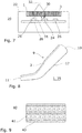
- a dental rod 35 as a further embodiment of a multi-fiber light guide 1 is shown in Fig. 8 .
- the dental rod 35 is shaped as an elongated light guide so that the length of the light guiding fibers 3 is greater than the largest lateral dimension of the glass element 9.
- a single light guiding fiber 3 is drawn as a hatched line to illustrate the orientation and arrangement of the light guiding fibers.
- the glass element 9 is stabilized to withstand impact shocks.
- the toughening may help to avoid breakage, if the tool with the dental rod is accidentally dropped.
- the embodiment of Fig. 8 is an example of further refinements of the multi-fiber light guide 1.
- the two abutting faces 10, 11 may differ in their cross section. This difference may include at least one of the surface area and the shape or outline of the abutting faces 10, 11.
- the surface areas of the cross sections are different, with the surface area of abutting face 11 being smaller than the surface area of opposite abutting face 10.
- the multi-fiber light guide 1 may be tapered, as it is also realized in the depicted example.
- the multi-fiber light guide 1 may include at least one bend.
- the aforementioned features may also be realized with a plate shaped multi-fiber light guide but are generally more effective for an elongated light guide 1.
- Both a bend and a taper of the glass element 9 may be produced by hot forming. A taper is generated by heating and axially drawing the glass element This way, the number of fibers 3 remains constant. However, the diameter of the fibers reduces along the taper.
- the multi-fiber light guide may be produced using a drawing process starting with an appropriate preform. By repeated drawing, the fiber diameters are sequentially reduced until fibers with small, in particular microscopic lateral dimensions are obtained.
- the multi-fiber light guide 1 may be produced with a method comprising the following steps which are also illustrated with respect to Fig. 9 to Fig. 12 :
- Fig. 9 shows the preform 40 in a cross sectional view.
- the glass element 43 may be a single element with through holes therein, into which the rods 41 are inserted. Alternatively, a multitude of glass elements 43 may be used which are arranged between the rods 41 and cover the outward facing sides of the rods 41.
- the rods 41 are fused to the one or more glass element 43, and the preform 40 is drawn to increase its length and reduce the lateral dimensions of the rods 41. Fusing may in particular be effected by the drawing step which also requires heating to soften the glass.
- Fig. 10 shows the drawn preform.
- the ends 45 of the preform 40 still have the original lateral dimensions, as the preform is clamped at its ends to apply a drawing force.
- the drawn part is then cut into sections 47. These sections are put together to form a further preform 48 as shown in Fig. 11 .
- the steps of assembling and drawing the preform 40 and cutting the drawn preform 40 into sections 47 may be repeated until the desired fiber dimensions are reached. Then, sections 47 are cut from the drawn preform which are glass elements 9 as described above.
- the sections 47 may be thin slices, which form faceplates as exemplary shown in Fig 1 or Fig. 7 or may be elongated as in the example of Fig. 8 .
- the glass elements 9 are immersed into a salt bath 50 within a container 51.
- a molten salt bath comprising molten potassium nitrate.
- the multi-fiber light guide 1 may be further processed before chemical strengthening. Specifically, the multi-fiber light guide 1 may be sealed into a socket or mount so that an assembly with the multi-fiber light guide 1 fixed in the socket is obtained. After sealing, the assembly with the multi-fiber light guide 1 and the socket is subjected to an alkali ion-exchange and chemically toughened. A composite 55 with a socket 53 and the multi-fiber light guide 1 sealed therein is shown in Fig. 13 .
- the chemical toughening of the multi-fiber light guide 1 may also be performed before producing the assembly.
- the ion exchange may be suppressed in sections of the multi-fiber light guide that are sealed to the socket 53 and are therefore covered.
- the glass solder may undergo an ion-exchange process as well so that the glass solder exhibits an ion-exchange layer.
- the socket 53 may be a metal, preferably a stainless steel, a ceramic or another glass.
- the socket 53 is a metal ring.
- the socket 53 may also be a housing part, e.g. of a housing for a wearable electronic device.
- the multi-fiber light guide 1 is soldered to the socket 53.
- the solder 57 between the multi-fiber light guide 1 and the socket 53 may be a glass solder.
Landscapes
- Life Sciences & Earth Sciences (AREA)
- Chemical & Material Sciences (AREA)
- Engineering & Computer Science (AREA)
- Health & Medical Sciences (AREA)
- Physics & Mathematics (AREA)
- Organic Chemistry (AREA)
- Materials Engineering (AREA)
- Geochemistry & Mineralogy (AREA)
- Cardiology (AREA)
- General Life Sciences & Earth Sciences (AREA)
- Optics & Photonics (AREA)
- General Chemical & Material Sciences (AREA)
- Chemical Kinetics & Catalysis (AREA)
- General Physics & Mathematics (AREA)
- Manufacturing & Machinery (AREA)
- Biomedical Technology (AREA)
- Heart & Thoracic Surgery (AREA)
- Public Health (AREA)
- Physiology (AREA)
- General Health & Medical Sciences (AREA)
- Animal Behavior & Ethology (AREA)
- Surgery (AREA)
- Molecular Biology (AREA)
- Medical Informatics (AREA)
- Veterinary Medicine (AREA)
- Pathology (AREA)
- Biophysics (AREA)
- Spectroscopy & Molecular Physics (AREA)
- Surface Treatment Of Glass (AREA)
- Optical Fibers, Optical Fiber Cores, And Optical Fiber Bundles (AREA)
- Optical Couplings Of Light Guides (AREA)
- Manufacture, Treatment Of Glass Fibers (AREA)
- Surface Treatment Of Glass Fibres Or Filaments (AREA)
- Light Guides In General And Applications Therefor (AREA)
- Glass Compositions (AREA)
Abstract
- a multitude of light guiding fibers (3), each of the fibers (3) comprising
- an elongated glass core (5), wherein
- the cores (5) are surrounded by a glass cladding (7) so that
- the cladding (7) with the cores (5) form a rigid continuous glass element (9), and
- wherein the cores (5) have a higher refractive index than the cladding (7) so that light can be guided by total reflection along the glass cores (5), and wherein the glass element (9) of the multi-fiber light guide (1) has two abutting faces (10, 11), with the cores (5) ending in both abutting faces (10, 11), so that light can be guided along the cores (5) from one abutting face (10) to the other abutting face (11), and wherein
- the glasses of the cores (5) and the cladding (7) contain alkali ions, and wherein
- the alkali ions of the glasses are at least partly exchanged by alkali ions of a higher atomic number within an ion exchange layer (13) at each of the abutting faces (10, 11), the exchanged alkali ions within the ion exchange layer (13) imparting a compressive stress at the abutting faces (10, 11) .
Description
- This disclosure generally concerns fiber optical light guides. Specifically, the disclosure relates to fiber optical devices with a multitude of merged light guiding fibers.
- One type of fiber optical light guides composed of merged optical fibers is a fiber optical face plate.
US 2008/0069505 A1 discloses a pixel display covered with a fiber optical faceplate which is mounted in a distance to the pixels. Further,US 2006/0008220 A1 describes an optical low-pass filter using a fiber face plate. - Fiber optical plates used in front of displays may serve to increase or decrease the viewing angle or generally to shift the image plane relative to the display. In a faceplate, the individual fibers are fused together so that the longitudinal direction of the fibers lies transverse to the faces of the faceplate. As the fibers are fused together in direction perpendicular to the faces of the faceplate, the fusing areas may provide weakening zones extending transversely through the plate. Further, the glasses for fiber optical light guides are chosen because of their optical properties. Thus, suitable glasses may not necessarily be the strongest glasses in terms of mechanical stability. Thus, rigid multi-fiber light guides are prone to breakage upon mechanical stress, in particular by an impact or shock.
- It is therefore an object of this disclosure to provide a multi-fiber light guide with an improved mechanical stability to avoid breakage. This object is achieved by the subject matter of the independent claims. The dependent claims define advantageous refinements.
- Accordingly, this disclosure provides a multi-fiber light guide, comprising a multitude of light guiding fibers, each of the fibers comprising an elongated glass core. The cores are surrounded by a glass cladding so that the cladding with the cores form a rigid continuous glass element. The cores have a higher refractive index than the cladding so that light can be guided by total reflection along the glass cores. The glass element (9) of the multi-fiber light guide has two abutting faces), with the cores ending in both abutting faces, so that light can be guided along the cores from one abutting face to the other. Further, the glasses of the cores and the cladding contain alkali ions. The alkali ions of the glasses are at least partly exchanged by alkali ions of a higher atomic number within an ion exchange layer at each of the abutting faces. This way, the exchanged alkali ions within the ion exchange layer impart a compressive stress at the abutting faces. Thus, a multi fiber light guide is provided which has chemically strengthened abutting faces. It has been surprisingly found that a continuous layer with compressive stress can be formed at the abutting faces although the glasses of the cores and the cladding differ in their chemical composition.
- According to one embodiment the glass element forming the multi-fiber light guide is a plate or disc., respectively. In this embodiment with a plate shaped or disc shaped glass element the abutting faces of the light guide are typically closer together than the longest lateral dimension of the glass element. Accordingly, the thickness of the disc or plate is smaller than the longest lateral dimension. As the thickness of the disc defines the length of fibers, similarly, the length of the light guiding fibers is smaller than the longest lateral dimension. A multi-fiber light guide of this type will in the following be referred to as a faceplate. Preferably, this condition also hold for the shortest lateral dimension of the disc or plate. Thus, preferably, the thickness of the plate or the length of the fibers or cores is smaller than the shortest lateral dimension of the disc.
- According to a further embodiment, the multi-fiber light guide has an elongated shape. In this embodiment, the fiber length is greater than the largest lateral dimension of the glass element.
- The multi-fiber light guide, a method for producing the same and devices including the light guide are hereinafter described in detail and with reference to the figures.
-
-
Fig. 1 shows a multi-fiber light guide in a cross sectional view. -
Fig. 2 shows a photographic image of an abutting face of a multi-fiber light guide. -
Fig. 3 and 4 show two examples of light guides with light absorbing elements. -
Fig. 5 shows a multi-fiber light guide with a circumferential shell. -
Fig. 6 shows diagrams of the transmission of a chemically toughened light guide in comparison to a not toughened light guide. - In
Fig. 7 a sensor arrangement with a multi-fiber light guide is shown. -
Fig. 8 shows a multi-fiber light guide shaped as a dental rod. -
Fig. 9 to Fig. 12 illustrate method steps to produce a multi-fiber light guide. -
Fig. 13 shows an assembly with a glass element. -
Fig. 1 shows an example of amulti-fiber light guide 1 having a disc or plate like shape. In this embodiment, the width w or its lateral dimension is generally larger than the thickness d or length of thelight guide 1. - Generally, the
light guide 1 comprises a multitude of light guidingfibers 3. Without restriction to the specific embodiment, thefibers 3 are arranged side by side so that their longitudinal directions are generally parallel to each other. Thefibers 3 comprise acore 5 embedded into acladding 7. The glasses ofcore 5 andcladding 7 are fused together so that thecores 5 and thecladding 7 form a continuousrigid glass element 9. Preferably, the individual fibers are of microscopic size to enable transfer of optical signals with high spatial resolution. According to one embodiment which is not restricted to the specific example shown inFig. 1 , the pitch or center-to center distance c of adjacentlight guiding fibers 3 is from 2 µm to 500 µm, preferably at most 200 µm. - The light guiding
fibers 3 end in both opposing abutting faces 10, 11 of theglass element 9. This way, as thefibers 3 connect the abutting faces 10, 11, thefibers 3 guide light received at one of theabutting faces abutting face - The interfaces between the
cores 5 and thecladding 7 extend in transverse direction to the abuttingfaces multi-fiber light guide 1, the abutting faces 10, 11 are subjected to an ion-exchange process so that ion-exchange layers 13 are formed at the surface of the abutting faces 10, 11. - To achieve a continuous ion-exchange layer it is preferred that the glasses of both the
cores 5 and thecladding 7 have compositions with alkali oxides. In the ion-exchange process the alkali ions of the glasses are partly exchanged by heavier alkali ions having a larger ion radius. This way, the ions impart a compressive stress to the glass within the ion-exchange layers 13. - Generally, if the ion-
exchange layer 13 is produced by fully immersing the glass element into a salt bath, the ion exchange occurs at the entire surface of theglass element 9. Thus, typically, according to a preferred embodiment, the ion-exchange layer 13 also extends along the outer circumferential surface orshell 12 which connects and extends between the two abutting faces 10, 11. -
Fig. 2 shows a photographic image of anabutting face multi-fiber light guide 1. Generally, as in the example ofFig. 2 , thecores 5 may have a hexagonal cross section. Further, generally and without restriction to the shape of the cross section of thecores 5, thecores 5 may be arranged in a hexagonal pattern. These features can be advantageous in several respects. If an image of a pixel display is transferred from one abutting face to the opposed face, the hexagonal pattern may help to avoid moire patterns at the abutting face where the light exits. Further, the honeycomb-like structure of the interfaces betweencores 5 and cladding may increase mechanical stability. - According to a further embodiment which is also realized in the example of
Fig. 2 , the glass of thecladding 7 may be at least partially light absorbing. This is generally advantageous to reduce cross-talk or light leaching between thefibers 3. According to one embodiment, which is also realized in the embodiment ofFig. 2 . the glass of thecladding 7 is a black glass. However, the glass may also be partially absorbing as it is the case for colored glasses. In this case, the glass has a spectrally dependent and spectrally varying absorption. For example, the glass may be brown, red or purple colored. - Another possibility to reduce cross talk between the
fibers 3 is to provide additional absorbing fibers within theglass element 9 which are located between thecores 5 of the light guiding fibers. Two examples of these embodiments are shown inFig. 3 and Fig. 4. Fig. 3 shows a stack of individuallight guiding fibers 3 withlight absorbing fibers 15 being located in interstices between thelight guiding fibers 3. Thefibers -
Fig. 4 shows an example of a multi-fiberlight guide 1 with the fibers fused together to form a rigidcontinuous glass element 9. In this example thecores 5 are arranged in a square pattern. At every second intersection of four cores 5 alight absorbing fiber 15 is arranged. Both thecores 5 and thelight absorbing fibers 5 are surrounded by thecladding 7. The additionallight absorbing fibers 15 within therigid glass element 9 provide an extra-mural absorption to reduce cross talk or to block light which obliquely transits the multi-fiberlight guide 1. - In this example, the multi-fiber
light guide 1 comprises three different glasses, i.e., the glass of thecores 5, the glass of thecladding 7 and the glass of thelight absorbing fibers 15. The glass of thelight absorbing fibers 15 may be similar to one of the other glasses but includes light absorbing pigments or dyes such as colouring ions. -
Fig. 5 shows a further embodiment of a multi-fiberlight guide 1. This light guide comprises acircumferential shell 17 which extends about the central arrangement offibers 3. Specifically, it is advantageous if thisshell 17 is made of glass as well so that theshell 17 forms an integral part of theglass element 9 of thelight guide 1. Accordingly, theglass element 9 comprises aglass shell 17 which encompasses the bundledfibers 3 or thecladding 7 in which thecores 5 are embedded, respectively. This way, the shell also forms an outer circumferential section of the abutting faces 10, 11. According to a refinement, the glass of thisshell 17 may differ from the glasses of thecores 5 and thecladding 3. Thus, in this embodiment theglass element 9 comprises three different glasses, i.e. the glasses of thecores 5, thecladding 7 and theshell 17. Further, it is advantageous if theglass shell 17 is chemically strengthened like thecores 5 and thecladding 7 so that a continuousion exchange layer 13 can be formed at the abutting faces 10, 11 by ion exchange. - The improved mechanical strength of multi-fiber light guides in the form of faceplates was investigated with a ball drop test. Faceplate samples of chemically toughened faceplates were compared to faceplates that have not been chemically toughened. All samples had a diameter of about 13 mm. The samples were positioned on a steel plate without damping material. A steel ball was dropped vertically onto the sample. The test was repeated with increased weight of the steel ball until the sample broke. The results are listed in the following table:
Not toughened samples Toughened samples Average weight of 3.6 6.2 ball [g] Standard deviation of the ball weight [g] 3,0 3.3 Minimum weight of steel ball [g] 1 1 Maximum weight of steel ball [g] 7 14 Tested samples 47 29 Number of samples broken with steel ball of 1 g weight 27 6 Number of samples broken with steel ball of 7 g weight 20 21 Number of samples broken with steel ball of 14 g weight 0 2 Percentage of samples broken with steel ball of 1 g weight 57.4% 20.7% Percentage of samples broken with steel ball of 7 g weight 42.6% 72.4% Percentage of samples broken with steel ball of 14 g weight 0.0% 6.9% - As it is evident from the above table, the mechanical strength against impact or shock is significantly increased by the chemical toughening. Nearly 80% of the chemically toughened samples withstand the 1 g ball drop test whereas more than half of the not toughened samples already break with the 1 g weight.
- Further, the ion exchange for the chemical toughening also does not adversely affect the optical properties of the multi-fiber light guide.
-
Fig. 6 shows diagrams of the transmission of a chemically toughened light guide in comparison to a not toughened light guide. For comparison, the transmission of a multi-fiber light guide was measured before toughening. Then the light guide was subjected to an ion-exchange for 20 hours. After this ion exchange procedure and chemical toughening, the transmission measurement was repeated. Curve (b) is the transmission before the ion exchange and curve (a) represents the transmission after the ion-exchange process or chemical toughening, respectively. As can be seen from the curves, the transmission remains nearly unaffected. Surprisingly, the transmission is even slightly higher after the ion exchange which may be attributed to refractive index changes in theion exchange layer 13. - The multi-fiber
light guide 1 according to this disclosure is particularly suited as a window for optical sensors. Therefore, according to one embodiment, an optical sensor arrangement is provided comprising a sensor element such as, e.g. a photodiode, whereby the sensor element is encased in a housing which comprises a multi-fiber light guide according to this disclosure. The multi fiber light guide is arranged so as to guide light from outside of the housing to the sensor element. To use a multi-fiber light guide as a window is further particularly advantageous if the sensor arrangement also includes a light source to probe and illuminate the object to be sensed by the sensor. In this case, the light guide can effectively suppress a direct signal path from the light source to the sensor, which results from an internal reflection at the outer abutting face of the window. This suppression allows to use a single common window for both the light source and the sensor. Accordingly, in a refinement of this embodiment the sensor arrangement comprises a light source, preferably a semiconductor light source such as a light emitting diode (LED) or laser diode (LD) within the housing, whereby the light source and the sensor element are so positioned with respect to the multi-fiber light guide that the light source emits light through the multi-fiber light guide and the sensor element receives light through the same multi-fiber light guide. - In
Fig. 7 such a sensor arrangement with a multi-fiberlight guide 1 is shown. The sensor arrangement comprises ahousing 22. The multi-fiberlight guide 1, preferably in form of a faceplate forms a part of thehousing 22 so that light can be transmitted inside the housing and vice versa. Thesensor arrangement 20 comprises asensor element 24. In a preferred embodiment, alight source 26 is included as well. Thesensor element 24 and thelight source 26 are mounted on a common printedcircuit board 28 facing the multi-fiberlight guide 1. As shown, theoptical sensor arrangement 20 may also include more than onelight sources 26. In the example shown, thesensor element 22 is arranged between twolight sources 26. - To illustrate the effect of the faceplate as a window for the
sensor element 24 and thelight source 26, twolight rays Light ray 31 would be a possible path if the window in thehousing 22 would be a simple transparent plate. This way, thelight ray 31 may be reflected at the outer face of the window and could then directly impinge onto thesensor element 24 without interaction within anexternal interaction zone 32. If instead a multi-fiberlight guide 1 is used as a window, thelight ray 31 is guided to the outer abutting face within alight guiding fiber 3. Even if the light ray would be reflected at the outer face, it would be guided back within thefiber 3 and therefore cannot reach the sensor element. This way, unwanted background signals are minimized. After being emitted from thesensor arrangement 22, the light ray can interact with anexternal interaction zone 32, re-enter thehousing 22 through thelight guide 1 and finally reach thesensor element 24. - To avoid background noise caused by a
light ray 30, one would need to use separate windows for thelight source 26 and thesensor element 24. In contrast, with the multi-fiber light guide, a single window with large enough diameter is sufficient and allows for a higher sensor and/or light source density within the same region. This brings higher integration in terms of optical sensing. - Generally, one preferred embodiment of a
sensor arrangement 20 is an optical heart rate monitor. Further, thesensor arrangement 20 may be a wearable device such as a smart watch. In case of a wearable device, e.g. in form of a wrist watch with an optical heart rate monitor, the housing is typically fastened to the body with the window or faceplate, respectively, contacting the skin. A wearable device is particularly prone to impacts, e.g., if the device is taken of and placed onto a hard surface. Due to the chemically toughened abutting faces, however, the probability for breakage or at least chipping of the outer surface due to impact stress is lowered. The multi-fiber light guide with theglass element 9 according to this disclosure is also considerably more durable compared to plastic windows which are frequently used for wearable devices. These plastic windows degrade over time and have performance issues with regards to waterproofing, durability and aesthetics. - In the above described examples, the multi-fiber
light guide 1 is plate shaped. However, it is also contemplated to use elongated light guides with the length of thelight guiding fibers 3 being greater than the largest lateral dimension of theglass element 9. One example is a dental rod. These rods are used to guide light to a treatment zone, e.g. to cure photo-polymerizable fillers for dental treatments. - A dental rod 35 as a further embodiment of a multi-fiber
light guide 1 is shown inFig. 8 . The dental rod 35 is shaped as an elongated light guide so that the length of thelight guiding fibers 3 is greater than the largest lateral dimension of theglass element 9. In the figure, a singlelight guiding fiber 3 is drawn as a hatched line to illustrate the orientation and arrangement of the light guiding fibers. As not only the abutting faces 10, 11 of the multi-fiberlight guide 1, but also theshell 17 are chemically toughened, theglass element 9 is stabilized to withstand impact shocks. For example, the toughening may help to avoid breakage, if the tool with the dental rod is accidentally dropped. - In addition, the embodiment of
Fig. 8 is an example of further refinements of the multi-fiberlight guide 1. According to a first refinement, the two abutting faces 10, 11 may differ in their cross section. This difference may include at least one of the surface area and the shape or outline of the abutting faces 10, 11. In the example, the surface areas of the cross sections are different, with the surface area of abuttingface 11 being smaller than the surface area of opposite abuttingface 10. Accordingly, the multi-fiberlight guide 1 may be tapered, as it is also realized in the depicted example. - Further, generally, the multi-fiber
light guide 1 may include at least one bend. The aforementioned features may also be realized with a plate shaped multi-fiber light guide but are generally more effective for an elongatedlight guide 1. Both a bend and a taper of theglass element 9 may be produced by hot forming. A taper is generated by heating and axially drawing the glass element This way, the number offibers 3 remains constant. However, the diameter of the fibers reduces along the taper. - Independent from the various shapes of a
light guide 1 as discussed herein, the multi-fiber light guide may be produced using a drawing process starting with an appropriate preform. By repeated drawing, the fiber diameters are sequentially reduced until fibers with small, in particular microscopic lateral dimensions are obtained. - Specifically, the multi-fiber
light guide 1 may be produced with a method comprising the following steps which are also illustrated with respect toFig. 9 to Fig. 12 : - providing a
preform 40 with at least onerod 41 of a first glass and at least oneglass element 43 of a second glass having a lower refractive index than the first glass, thepreform 40 being assembled, so that therod 41 is surrounded by the second glass, - heating the preform and fusing the
rods 41 to the at least oneglass element 43, and - drawing the
preform 40 to increase its length and reduce the lateral dimensions of therods 41, - cutting the drawn
preform 40 intosections 47 and - assembling the sections to form a
further preform 40, wherein the steps of assembling thesections 47 to a new preform, drawing the new preform and cutting the drawnpreform 40 intosections 47 is preferably repeated at least once, - cutting
sections 47 from thepreform 40 to obtainglass elements 9 as described herein, comprising a multitude oflight guiding fibers 3 with a core of the first glass surrounded by a cladding of the second glass, - immersing the glass elements into a
salt bath 50 containing alkali ions to effect an ion exchange with the alkali ions in the glasses of theglass element 9 and to form anion exchange layer 13 at the surface of the glass element which exerts a compressive stress to the glass. -
Fig. 9 shows thepreform 40 in a cross sectional view. Theglass element 43 may be a single element with through holes therein, into which therods 41 are inserted. Alternatively, a multitude ofglass elements 43 may be used which are arranged between therods 41 and cover the outward facing sides of therods 41. - The
rods 41 are fused to the one ormore glass element 43, and thepreform 40 is drawn to increase its length and reduce the lateral dimensions of therods 41. Fusing may in particular be effected by the drawing step which also requires heating to soften the glass.Fig. 10 shows the drawn preform. The ends 45 of thepreform 40 still have the original lateral dimensions, as the preform is clamped at its ends to apply a drawing force. The drawn part is then cut intosections 47. These sections are put together to form a further preform 48 as shown inFig. 11 . The steps of assembling and drawing thepreform 40 and cutting the drawnpreform 40 intosections 47 may be repeated until the desired fiber dimensions are reached. Then,sections 47 are cut from the drawn preform which areglass elements 9 as described above. Thesections 47 may be thin slices, which form faceplates as exemplary shown inFig 1 orFig. 7 or may be elongated as in the example ofFig. 8 . Finally, as shown inFig. 12 , theglass elements 9 are immersed into asalt bath 50 within acontainer 51. Suitable for toughening glass elements with sodium containing glasses is a molten salt bath comprising molten potassium nitrate. - According to a variant of the method, the multi-fiber
light guide 1 may be further processed before chemical strengthening. Specifically, the multi-fiberlight guide 1 may be sealed into a socket or mount so that an assembly with the multi-fiberlight guide 1 fixed in the socket is obtained. After sealing, the assembly with the multi-fiberlight guide 1 and the socket is subjected to an alkali ion-exchange and chemically toughened. A composite 55 with asocket 53 and the multi-fiberlight guide 1 sealed therein is shown inFig. 13 . Of course, according to an alternative embodiment, the chemical toughening of the multi-fiberlight guide 1 may also be performed before producing the assembly. If the multi-fiberlight guide 1 is chemically toughened while sealed in thesocket 53, the ion exchange may be suppressed in sections of the multi-fiber light guide that are sealed to thesocket 53 and are therefore covered. Vice versa, if a glass solder with alkali oxide content is used, the glass solder may undergo an ion-exchange process as well so that the glass solder exhibits an ion-exchange layer. Thus, it can be verified from theassembly 55, whether the multi-fiberlight guide 1 was sealed to thesocket 53 before or after the chemical toughening. - The
socket 53 may be a metal, preferably a stainless steel, a ceramic or another glass. In one embodiment, thesocket 53 is a metal ring. However, thesocket 53 may also be a housing part, e.g. of a housing for a wearable electronic device. According to a further embodiment which is also realized in the depicted example, the multi-fiberlight guide 1 is soldered to thesocket 53. Thesolder 57 between the multi-fiberlight guide 1 and thesocket 53 may be a glass solder.List of reference signs 1 Multi-fiber light guide 3 Fiber 5 Core of fiber 37 Cladding 9 Glass element 10, 11 Abutting face of light guide 112 Side of light guide 113 Ion exchange layer 15 Absorbing fiber 17 Shell 20 Optical sensor arrangement 22 Housing of optical sensor arrangement 2024 Sensor element 26 Light source 28 Printed circuit board 30, 31 Light ray 32 Interaction zone 35 Dental rod 40 Preform 41 Rod 43 Glass element 45 End of 40 47 Section cut from drawn preform 4050 Salt bath 51 Container 53 Socket 55 Assembly 57 Solder
Claims (15)
- A multi-fiber light guide (1) comprising- a multitude of light guiding fibers (3), each of the fibers (3) comprising- an elongated glass core (5), wherein- the cores (5) are surrounded by a glass cladding (7) so that- the cladding (7) with the cores (5) form a rigid continuous glass element (9), and- wherein the cores (5) have a higher refractive index than the cladding (7) so that light can be guided by total reflection along the glass cores (5), and wherein the glass element (9) of the multi-fiber light guide (1) has two abutting faces (10, 11), with the cores (5) ending in both abutting faces (10, 11), so that light can be guided along the cores (5) from one abutting face (10) to the other abutting face (11), and wherein- the glasses of the cores (5) and the cladding (7) contain alkali ions, and wherein- the alkali ions of the glasses are at least partly exchanged by alkali ions of a higher atomic number within an ion exchange layer (13) at each of the abutting faces (10, 11), the exchanged alkali ions within the ion exchange layer (13) imparting a compressive stress at the abutting faces (10, 11) .
- The multi-fiber light guide (1) according to the preceding claim, wherein the ion-exchange layer (13) also extends along the shell (12) of the glass element (9) which extends between the two abutting faces (10, 11).
- The multi-fiber light guide (1) according to one of the preceding claims, characterized in that the glass element is a disc with the thickness of the disc being smaller than the shortest lateral dimension of the disc.
- The multi-fiber light guide (1) according to one of claims 1 or 2, wherein the multi-fiber light guide (1) has an elongated shape and the length of the light guiding fibers (3) is greater than the largest lateral dimension of the glass element (9).
- The multi-fiber light guide (1) according to the preceding claim, comprising at least one of the following features:- the abutting faces (10, 11) differ in their surface area,- the abutting faces (10, 11) differ in their shape,- the glass element (9) includes at least one bend.
- The multi-fiber light guide (1) according to one of the preceding claims, characterized by at least one of the following features:- the cores (5) are arranged in a hexagonal pattern,- the glass of the cladding (7) is light absorbing,- the glass element (9) of the multi-fiber light guide (1) comprises light absorbing fibers (15),- the center-to center distance of adjacent light guiding fibers (3) is from 2 µm to 500 µm, preferably at most 200 µm.
- The multi-fiber light guide (1) according to one of the preceding claims, wherein the glass element (9) comprises a glass shell (17) which encompasses the cladding (7) with the embedded cores (5).
- An assembly (53) comprising a multi-fiber light guide (1) according to one on the preceding claims, sealed into a socket (53).
- The assembly (53) according to the preceding claims, wherein the multi-fiber light guide (1) is chemically toughened while sealed in the socket (53).
- Optical sensor arrangement (20) comprising a sensor element (24), the sensor element (24) being encased in a housing (22) which comprises a multi-fiber light guide (1) according to one of the preceding claims 1 to 7 to guide light from outside of the housing (22) to the sensor element (24).
- Optical sensor arrangement (20) according to the preceding claim, further comprising a light source (26), preferably a semiconductor light source within the housing (22), whereby the light source (26) and the sensor element (24) are positioned with respect to the multi-fiber light guide (1) so that the light source (26) emits light through the multi-fiber light guide and the sensor element receives light through the same multi-fiber light guide.
- Optical sensor arrangement (20) according to one of the two preceding claims, wherein the optical sensor arrangement (20) is an optical heart rate monitor.
- Optical sensor arrangement (20) according to one of the three preceding claims, wherein the optical sensor arrangement (20) is a wearable device.
- Method for producing a multi-fiber light guide (1) according to one of claims 1 to 7, comprising the steps of:- providing a preform (40) with at least one rod (41) of a first glass and at least one glass element (43) of a second glass having a lower refractive index than the first glass, the preform (40) being assembled, so that the rod (41) is surrounded by the second glass,- heating the preform and fusing the rods (41) to the at least one glass element (43), and- drawing the preform (40) to increase its length and reduce the lateral dimensions of the rods (41),- cutting the drawn preform (40) into sections (47) and- assembling the sections to form a further preform (40), wherein the steps of assembling the sections (47) to a new preform, drawing the new preform (40) and cutting the drawn preform (40) into sections (47) is preferably repeated at least once,- cutting sections (47) from the preform (40) to obtain glass elements (9), comprising a multitude of light guiding fibers (3) with a core (5) of the first glass surrounded by a cladding (7) of the second glass,- immersing the glass elements into a salt bath (50) containing alkali ions to effect an ion exchange with the alkali ions in the glasses of the glass element (9) and to form an ion exchange layer (13) at the surface of the glass element (9) which exerts a compressive stress to the glass.
- Method according to the preceding claim wherein the multi-fiber light guide (1) is sealed into a socket (53) and wherein the assembly (55) with the multi-fiber light guide 1 and the socket is chemically toughened after sealing.
Priority Applications (5)
| Application Number | Priority Date | Filing Date | Title |
|---|---|---|---|
| EP20172235.2A EP3904306B1 (en) | 2020-04-30 | 2020-04-30 | Multi-fiber light guide, device with a multi-fiber light guide and method for producing the same |
| CN202180032206.0A CN115551816B (en) | 2020-04-30 | 2021-04-26 | Multi-fiber light guides, devices with multi-fiber light guides and methods of manufacturing the same |
| JP2022565941A JP2023523357A (en) | 2020-04-30 | 2021-04-26 | Multi-fiber light guide, device with multi-fiber light guide, and manufacturing method thereof |
| PCT/EP2021/060852 WO2021219559A1 (en) | 2020-04-30 | 2021-04-26 | Multi-fiber light guide, device with a multi-fiber light guide and method for producing the same |
| US17/975,979 US12292594B2 (en) | 2020-04-30 | 2022-10-28 | Multi-fiber light guide, device with a multi-fiber light guide and method for producing the same |
Applications Claiming Priority (1)
| Application Number | Priority Date | Filing Date | Title |
|---|---|---|---|
| EP20172235.2A EP3904306B1 (en) | 2020-04-30 | 2020-04-30 | Multi-fiber light guide, device with a multi-fiber light guide and method for producing the same |
Publications (3)
| Publication Number | Publication Date |
|---|---|
| EP3904306A1 true EP3904306A1 (en) | 2021-11-03 |
| EP3904306A8 EP3904306A8 (en) | 2022-05-25 |
| EP3904306B1 EP3904306B1 (en) | 2023-06-07 |
Family
ID=70482277
Family Applications (1)
| Application Number | Title | Priority Date | Filing Date |
|---|---|---|---|
| EP20172235.2A Active EP3904306B1 (en) | 2020-04-30 | 2020-04-30 | Multi-fiber light guide, device with a multi-fiber light guide and method for producing the same |
Country Status (5)
| Country | Link |
|---|---|
| US (1) | US12292594B2 (en) |
| EP (1) | EP3904306B1 (en) |
| JP (1) | JP2023523357A (en) |
| CN (1) | CN115551816B (en) |
| WO (1) | WO2021219559A1 (en) |
Families Citing this family (2)
| Publication number | Priority date | Publication date | Assignee | Title |
|---|---|---|---|---|
| EP3904306B1 (en) * | 2020-04-30 | 2023-06-07 | Schott Ag | Multi-fiber light guide, device with a multi-fiber light guide and method for producing the same |
| CN117075261B (en) * | 2023-09-28 | 2024-04-05 | 中建材光芯科技有限公司 | Low-magnification high-strength optical fiber cone and preparation method and application thereof |
Citations (6)
| Publication number | Priority date | Publication date | Assignee | Title |
|---|---|---|---|---|
| DE19830335A1 (en) * | 1997-07-07 | 1999-01-14 | Schmidt Es Bender Hungaria Kft | Method for producing an optical fibre light guide, and resultant light guide |
| US20060008220A1 (en) | 2004-06-24 | 2006-01-12 | Schott Ag | Optical lowpass filter and method for producing an optical lowpass filter |
| US20080069505A1 (en) | 2006-09-14 | 2008-03-20 | Schott Ag | Display device with fiber-optic arrangement |
| US20150153510A1 (en) * | 2012-08-08 | 2015-06-04 | Asahi Glass Company, Limited | Glass optical waveguide body and cover glass |
| US20190076036A1 (en) * | 2015-10-27 | 2019-03-14 | Nokia Technologies Oy | A Sensor Element |
| US20190154915A1 (en) * | 2008-11-19 | 2019-05-23 | Hamamatsu Photonics K.K. | Fiber optic plate and method for producing the same |
Family Cites Families (7)
| Publication number | Priority date | Publication date | Assignee | Title |
|---|---|---|---|---|
| NL6612387A (en) * | 1966-09-02 | 1968-03-04 | ||
| DE1901053B1 (en) * | 1969-01-10 | 1970-06-04 | Jenaer Glaswerk Schott & Gen | Optical fiber and its method of manufacture |
| GB1289773A (en) * | 1969-02-06 | 1972-09-20 | ||
| US8789998B2 (en) * | 2011-08-31 | 2014-07-29 | Corning Incorporated | Edge illumination of an ion-exchanged glass sheet |
| KR102290967B1 (en) * | 2013-08-27 | 2021-08-19 | 코닝 인코포레이티드 | Damage resistant glass with high coefficient of thermal expansion |
| EP3904306B1 (en) * | 2020-04-30 | 2023-06-07 | Schott Ag | Multi-fiber light guide, device with a multi-fiber light guide and method for producing the same |
| US11573450B1 (en) * | 2020-09-23 | 2023-02-07 | Apple Inc. | Electronic devices with chemically strengthened coherent fiber bundles |
-
2020
- 2020-04-30 EP EP20172235.2A patent/EP3904306B1/en active Active
-
2021
- 2021-04-26 CN CN202180032206.0A patent/CN115551816B/en active Active
- 2021-04-26 WO PCT/EP2021/060852 patent/WO2021219559A1/en not_active Ceased
- 2021-04-26 JP JP2022565941A patent/JP2023523357A/en active Pending
-
2022
- 2022-10-28 US US17/975,979 patent/US12292594B2/en active Active
Patent Citations (6)
| Publication number | Priority date | Publication date | Assignee | Title |
|---|---|---|---|---|
| DE19830335A1 (en) * | 1997-07-07 | 1999-01-14 | Schmidt Es Bender Hungaria Kft | Method for producing an optical fibre light guide, and resultant light guide |
| US20060008220A1 (en) | 2004-06-24 | 2006-01-12 | Schott Ag | Optical lowpass filter and method for producing an optical lowpass filter |
| US20080069505A1 (en) | 2006-09-14 | 2008-03-20 | Schott Ag | Display device with fiber-optic arrangement |
| US20190154915A1 (en) * | 2008-11-19 | 2019-05-23 | Hamamatsu Photonics K.K. | Fiber optic plate and method for producing the same |
| US20150153510A1 (en) * | 2012-08-08 | 2015-06-04 | Asahi Glass Company, Limited | Glass optical waveguide body and cover glass |
| US20190076036A1 (en) * | 2015-10-27 | 2019-03-14 | Nokia Technologies Oy | A Sensor Element |
Also Published As
| Publication number | Publication date |
|---|---|
| EP3904306B1 (en) | 2023-06-07 |
| US12292594B2 (en) | 2025-05-06 |
| EP3904306A8 (en) | 2022-05-25 |
| CN115551816A (en) | 2022-12-30 |
| JP2023523357A (en) | 2023-06-02 |
| WO2021219559A1 (en) | 2021-11-04 |
| US20230067347A1 (en) | 2023-03-02 |
| CN115551816B (en) | 2024-03-19 |
Similar Documents
| Publication | Publication Date | Title |
|---|---|---|
| US12292594B2 (en) | Multi-fiber light guide, device with a multi-fiber light guide and method for producing the same | |
| CN103443603B (en) | The surface stress determinator of glass and the surface stress assay method of glass | |
| JP5259096B2 (en) | Fiber optic and manufacturing method thereof | |
| JP3488483B2 (en) | Optical fiber array for image transmission and waveguide image transmission array and processing method of its end face | |
| JP5165443B2 (en) | Silica-based multi-core optical fiber | |
| US20020039472A1 (en) | Preliminary member of optical device component with optical fiber | |
| DE102018127619B4 (en) | Wearable electronic device and process for its manufacture | |
| JPS5937451B2 (en) | Surface stress measuring device for chemically strengthened glass | |
| EP3877793B1 (en) | System comprising an optical fiber and method of its use | |
| CN101299076B (en) | Optical fibre bundle and light source apparatus | |
| EP1076247B1 (en) | Bundle of optical fibres for image transmission | |
| US20070137255A1 (en) | Optical device and method of manufacturing the optical same | |
| WO2023242063A1 (en) | Thermal expansion-balanced transverse anderson localization optical waveguides that have reduced bowing | |
| JP4356103B2 (en) | Spare material with optical fiber | |
| TWI806975B (en) | Prism coupling methods of characterizing stress in glass-based ion-exchanged articles having problematic refractive index profiles | |
| CN119620505B (en) | Double-cladding square chalcogenide optical fiber and preparation method of fiber grating based on double-cladding square chalcogenide optical fiber | |
| JP4121375B2 (en) | Optical components | |
| CN121268343A (en) | Composite glass cover plate and preparation method and application thereof | |
| JP2003050337A (en) | Method for manufacturing optical fiber stub, and optical fiber stub | |
| DE202018006483U1 (en) | Wearable electronic device | |
| CN121463362A (en) | Double-layer composite optical glass cover plate and preparation method and application thereof | |
| DE102018010363A1 (en) | Wearable electronic device and method of making the same | |
| WO2025255058A1 (en) | Waveguides using transverse anderson localization and having an optically active material for improved contrast | |
| JPH10208022A (en) | Fiber optical plate | |
| JP2006058740A (en) | Composite optical fiber |
Legal Events
| Date | Code | Title | Description |
|---|---|---|---|
| STAA | Information on the status of an ep patent application or granted ep patent |
Free format text: STATUS: EXAMINATION IS IN PROGRESS |
|
| PUAI | Public reference made under article 153(3) epc to a published international application that has entered the european phase |
Free format text: ORIGINAL CODE: 0009012 |
|
| 17P | Request for examination filed |
Effective date: 20200430 |
|
| AK | Designated contracting states |
Kind code of ref document: A1 Designated state(s): AL AT BE BG CH CY CZ DE DK EE ES FI FR GB GR HR HU IE IS IT LI LT LU LV MC MK MT NL NO PL PT RO RS SE SI SK SM TR |
|
| B565 | Issuance of search results under rule 164(2) epc |
Effective date: 20201014 |
|
| RIN1 | Information on inventor provided before grant (corrected) |
Inventor name: STEIGLEDER, JAN Inventor name: WEISSHUHN, JULIA Inventor name: HETTLER, ROBERT Inventor name: CHAI, WEE KIAT |
|
| RBV | Designated contracting states (corrected) |
Designated state(s): AL AT BE BG CH CY CZ DE DK EE ES FI FR GB GR HR HU IE IS IT LI LT LU LV MC MK MT NL NO PL PT RO RS SE SI SK SM TR |
|
| GRAP | Despatch of communication of intention to grant a patent |
Free format text: ORIGINAL CODE: EPIDOSNIGR1 |
|
| STAA | Information on the status of an ep patent application or granted ep patent |
Free format text: STATUS: GRANT OF PATENT IS INTENDED |
|
| INTG | Intention to grant announced |
Effective date: 20230116 |
|
| GRAS | Grant fee paid |
Free format text: ORIGINAL CODE: EPIDOSNIGR3 |
|
| GRAA | (expected) grant |
Free format text: ORIGINAL CODE: 0009210 |
|
| STAA | Information on the status of an ep patent application or granted ep patent |
Free format text: STATUS: THE PATENT HAS BEEN GRANTED |
|
| RIN1 | Information on inventor provided before grant (corrected) |
Inventor name: STEIGLEDER, JAN Inventor name: WEISSHUHN, JULIA Inventor name: HETTLER, ROBERT Inventor name: CHAI, WEE KIAT |
|
| AK | Designated contracting states |
Kind code of ref document: B1 Designated state(s): AL AT BE BG CH CY CZ DE DK EE ES FI FR GB GR HR HU IE IS IT LI LT LU LV MC MK MT NL NO PL PT RO RS SE SI SK SM TR |
|
| REG | Reference to a national code |
Ref country code: GB Ref legal event code: FG4D |
|
| REG | Reference to a national code |
Ref country code: CH Ref legal event code: EP Ref country code: AT Ref legal event code: REF Ref document number: 1574616 Country of ref document: AT Kind code of ref document: T Effective date: 20230615 |
|
| P01 | Opt-out of the competence of the unified patent court (upc) registered |
Effective date: 20230516 |
|
| REG | Reference to a national code |
Ref country code: DE Ref legal event code: R096 Ref document number: 602020011542 Country of ref document: DE |
|
| REG | Reference to a national code |
Ref country code: LT Ref legal event code: MG9D |
|
| REG | Reference to a national code |
Ref country code: NL Ref legal event code: MP Effective date: 20230607 |
|
| PG25 | Lapsed in a contracting state [announced via postgrant information from national office to epo] |
Ref country code: SE Free format text: LAPSE BECAUSE OF FAILURE TO SUBMIT A TRANSLATION OF THE DESCRIPTION OR TO PAY THE FEE WITHIN THE PRESCRIBED TIME-LIMIT Effective date: 20230607 Ref country code: NO Free format text: LAPSE BECAUSE OF FAILURE TO SUBMIT A TRANSLATION OF THE DESCRIPTION OR TO PAY THE FEE WITHIN THE PRESCRIBED TIME-LIMIT Effective date: 20230907 Ref country code: ES Free format text: LAPSE BECAUSE OF FAILURE TO SUBMIT A TRANSLATION OF THE DESCRIPTION OR TO PAY THE FEE WITHIN THE PRESCRIBED TIME-LIMIT Effective date: 20230607 |
|
| REG | Reference to a national code |
Ref country code: AT Ref legal event code: MK05 Ref document number: 1574616 Country of ref document: AT Kind code of ref document: T Effective date: 20230607 |
|
| PG25 | Lapsed in a contracting state [announced via postgrant information from national office to epo] |
Ref country code: RS Free format text: LAPSE BECAUSE OF FAILURE TO SUBMIT A TRANSLATION OF THE DESCRIPTION OR TO PAY THE FEE WITHIN THE PRESCRIBED TIME-LIMIT Effective date: 20230607 Ref country code: NL Free format text: LAPSE BECAUSE OF FAILURE TO SUBMIT A TRANSLATION OF THE DESCRIPTION OR TO PAY THE FEE WITHIN THE PRESCRIBED TIME-LIMIT Effective date: 20230607 Ref country code: LV Free format text: LAPSE BECAUSE OF FAILURE TO SUBMIT A TRANSLATION OF THE DESCRIPTION OR TO PAY THE FEE WITHIN THE PRESCRIBED TIME-LIMIT Effective date: 20230607 Ref country code: LT Free format text: LAPSE BECAUSE OF FAILURE TO SUBMIT A TRANSLATION OF THE DESCRIPTION OR TO PAY THE FEE WITHIN THE PRESCRIBED TIME-LIMIT Effective date: 20230607 Ref country code: HR Free format text: LAPSE BECAUSE OF FAILURE TO SUBMIT A TRANSLATION OF THE DESCRIPTION OR TO PAY THE FEE WITHIN THE PRESCRIBED TIME-LIMIT Effective date: 20230607 Ref country code: GR Free format text: LAPSE BECAUSE OF FAILURE TO SUBMIT A TRANSLATION OF THE DESCRIPTION OR TO PAY THE FEE WITHIN THE PRESCRIBED TIME-LIMIT Effective date: 20230908 |
|
| PG25 | Lapsed in a contracting state [announced via postgrant information from national office to epo] |
Ref country code: FI Free format text: LAPSE BECAUSE OF FAILURE TO SUBMIT A TRANSLATION OF THE DESCRIPTION OR TO PAY THE FEE WITHIN THE PRESCRIBED TIME-LIMIT Effective date: 20230607 |
|
| PG25 | Lapsed in a contracting state [announced via postgrant information from national office to epo] |
Ref country code: SK Free format text: LAPSE BECAUSE OF FAILURE TO SUBMIT A TRANSLATION OF THE DESCRIPTION OR TO PAY THE FEE WITHIN THE PRESCRIBED TIME-LIMIT Effective date: 20230607 |
|
| PG25 | Lapsed in a contracting state [announced via postgrant information from national office to epo] |
Ref country code: IS Free format text: LAPSE BECAUSE OF FAILURE TO SUBMIT A TRANSLATION OF THE DESCRIPTION OR TO PAY THE FEE WITHIN THE PRESCRIBED TIME-LIMIT Effective date: 20231007 |
|
| PG25 | Lapsed in a contracting state [announced via postgrant information from national office to epo] |
Ref country code: SM Free format text: LAPSE BECAUSE OF FAILURE TO SUBMIT A TRANSLATION OF THE DESCRIPTION OR TO PAY THE FEE WITHIN THE PRESCRIBED TIME-LIMIT Effective date: 20230607 Ref country code: SK Free format text: LAPSE BECAUSE OF FAILURE TO SUBMIT A TRANSLATION OF THE DESCRIPTION OR TO PAY THE FEE WITHIN THE PRESCRIBED TIME-LIMIT Effective date: 20230607 Ref country code: RO Free format text: LAPSE BECAUSE OF FAILURE TO SUBMIT A TRANSLATION OF THE DESCRIPTION OR TO PAY THE FEE WITHIN THE PRESCRIBED TIME-LIMIT Effective date: 20230607 Ref country code: PT Free format text: LAPSE BECAUSE OF FAILURE TO SUBMIT A TRANSLATION OF THE DESCRIPTION OR TO PAY THE FEE WITHIN THE PRESCRIBED TIME-LIMIT Effective date: 20231009 Ref country code: IS Free format text: LAPSE BECAUSE OF FAILURE TO SUBMIT A TRANSLATION OF THE DESCRIPTION OR TO PAY THE FEE WITHIN THE PRESCRIBED TIME-LIMIT Effective date: 20231007 Ref country code: EE Free format text: LAPSE BECAUSE OF FAILURE TO SUBMIT A TRANSLATION OF THE DESCRIPTION OR TO PAY THE FEE WITHIN THE PRESCRIBED TIME-LIMIT Effective date: 20230607 Ref country code: CZ Free format text: LAPSE BECAUSE OF FAILURE TO SUBMIT A TRANSLATION OF THE DESCRIPTION OR TO PAY THE FEE WITHIN THE PRESCRIBED TIME-LIMIT Effective date: 20230607 Ref country code: AT Free format text: LAPSE BECAUSE OF FAILURE TO SUBMIT A TRANSLATION OF THE DESCRIPTION OR TO PAY THE FEE WITHIN THE PRESCRIBED TIME-LIMIT Effective date: 20230607 |
|
| PG25 | Lapsed in a contracting state [announced via postgrant information from national office to epo] |
Ref country code: PL Free format text: LAPSE BECAUSE OF FAILURE TO SUBMIT A TRANSLATION OF THE DESCRIPTION OR TO PAY THE FEE WITHIN THE PRESCRIBED TIME-LIMIT Effective date: 20230607 |
|
| REG | Reference to a national code |
Ref country code: DE Ref legal event code: R097 Ref document number: 602020011542 Country of ref document: DE |
|
| PLBE | No opposition filed within time limit |
Free format text: ORIGINAL CODE: 0009261 |
|
| STAA | Information on the status of an ep patent application or granted ep patent |
Free format text: STATUS: NO OPPOSITION FILED WITHIN TIME LIMIT |
|
| PG25 | Lapsed in a contracting state [announced via postgrant information from national office to epo] |
Ref country code: DK Free format text: LAPSE BECAUSE OF FAILURE TO SUBMIT A TRANSLATION OF THE DESCRIPTION OR TO PAY THE FEE WITHIN THE PRESCRIBED TIME-LIMIT Effective date: 20230607 |
|
| PG25 | Lapsed in a contracting state [announced via postgrant information from national office to epo] |
Ref country code: SI Free format text: LAPSE BECAUSE OF FAILURE TO SUBMIT A TRANSLATION OF THE DESCRIPTION OR TO PAY THE FEE WITHIN THE PRESCRIBED TIME-LIMIT Effective date: 20230607 |
|
| 26N | No opposition filed |
Effective date: 20240308 |
|
| PG25 | Lapsed in a contracting state [announced via postgrant information from national office to epo] |
Ref country code: SI Free format text: LAPSE BECAUSE OF FAILURE TO SUBMIT A TRANSLATION OF THE DESCRIPTION OR TO PAY THE FEE WITHIN THE PRESCRIBED TIME-LIMIT Effective date: 20230607 Ref country code: IT Free format text: LAPSE BECAUSE OF FAILURE TO SUBMIT A TRANSLATION OF THE DESCRIPTION OR TO PAY THE FEE WITHIN THE PRESCRIBED TIME-LIMIT Effective date: 20230607 |
|
| PG25 | Lapsed in a contracting state [announced via postgrant information from national office to epo] |
Ref country code: BG Free format text: LAPSE BECAUSE OF FAILURE TO SUBMIT A TRANSLATION OF THE DESCRIPTION OR TO PAY THE FEE WITHIN THE PRESCRIBED TIME-LIMIT Effective date: 20230607 |
|
| PG25 | Lapsed in a contracting state [announced via postgrant information from national office to epo] |
Ref country code: MC Free format text: LAPSE BECAUSE OF FAILURE TO SUBMIT A TRANSLATION OF THE DESCRIPTION OR TO PAY THE FEE WITHIN THE PRESCRIBED TIME-LIMIT Effective date: 20230607 |
|
| PG25 | Lapsed in a contracting state [announced via postgrant information from national office to epo] |
Ref country code: MC Free format text: LAPSE BECAUSE OF FAILURE TO SUBMIT A TRANSLATION OF THE DESCRIPTION OR TO PAY THE FEE WITHIN THE PRESCRIBED TIME-LIMIT Effective date: 20230607 Ref country code: BG Free format text: LAPSE BECAUSE OF FAILURE TO SUBMIT A TRANSLATION OF THE DESCRIPTION OR TO PAY THE FEE WITHIN THE PRESCRIBED TIME-LIMIT Effective date: 20230607 |
|
| REG | Reference to a national code |
Ref country code: CH Ref legal event code: PL |
|
| PG25 | Lapsed in a contracting state [announced via postgrant information from national office to epo] |
Ref country code: LU Free format text: LAPSE BECAUSE OF NON-PAYMENT OF DUE FEES Effective date: 20240430 |
|
| GBPC | Gb: european patent ceased through non-payment of renewal fee |
Effective date: 20240430 |
|
| REG | Reference to a national code |
Ref country code: BE Ref legal event code: MM Effective date: 20240430 |
|
| PG25 | Lapsed in a contracting state [announced via postgrant information from national office to epo] |
Ref country code: LU Free format text: LAPSE BECAUSE OF NON-PAYMENT OF DUE FEES Effective date: 20240430 |
|
| PG25 | Lapsed in a contracting state [announced via postgrant information from national office to epo] |
Ref country code: BE Free format text: LAPSE BECAUSE OF NON-PAYMENT OF DUE FEES Effective date: 20240430 |
|
| PG25 | Lapsed in a contracting state [announced via postgrant information from national office to epo] |
Ref country code: GB Free format text: LAPSE BECAUSE OF NON-PAYMENT OF DUE FEES Effective date: 20240430 |
|
| PG25 | Lapsed in a contracting state [announced via postgrant information from national office to epo] |
Ref country code: FR Free format text: LAPSE BECAUSE OF NON-PAYMENT OF DUE FEES Effective date: 20240430 |
|
| PG25 | Lapsed in a contracting state [announced via postgrant information from national office to epo] |
Ref country code: GB Free format text: LAPSE BECAUSE OF NON-PAYMENT OF DUE FEES Effective date: 20240430 Ref country code: FR Free format text: LAPSE BECAUSE OF NON-PAYMENT OF DUE FEES Effective date: 20240430 Ref country code: BE Free format text: LAPSE BECAUSE OF NON-PAYMENT OF DUE FEES Effective date: 20240430 Ref country code: CH Free format text: LAPSE BECAUSE OF NON-PAYMENT OF DUE FEES Effective date: 20240430 |
|
| PG25 | Lapsed in a contracting state [announced via postgrant information from national office to epo] |
Ref country code: IE Free format text: LAPSE BECAUSE OF NON-PAYMENT OF DUE FEES Effective date: 20240430 |
|
| PGFP | Annual fee paid to national office [announced via postgrant information from national office to epo] |
Ref country code: DE Payment date: 20250422 Year of fee payment: 6 |
|
| PG25 | Lapsed in a contracting state [announced via postgrant information from national office to epo] |
Ref country code: CY Free format text: LAPSE BECAUSE OF FAILURE TO SUBMIT A TRANSLATION OF THE DESCRIPTION OR TO PAY THE FEE WITHIN THE PRESCRIBED TIME-LIMIT; INVALID AB INITIO Effective date: 20200430 |
|
| PG25 | Lapsed in a contracting state [announced via postgrant information from national office to epo] |
Ref country code: HU Free format text: LAPSE BECAUSE OF FAILURE TO SUBMIT A TRANSLATION OF THE DESCRIPTION OR TO PAY THE FEE WITHIN THE PRESCRIBED TIME-LIMIT; INVALID AB INITIO Effective date: 20200430 |