EP3904285A1 - Carbon nanotube production method, carbon nanotube assembly wire production method, carbon nanotube assembly wire bundle production method, carbon nanotube production device, carbon nanotube assembly wire production device and carbon nanotube assembly wire bundle production device - Google Patents
Carbon nanotube production method, carbon nanotube assembly wire production method, carbon nanotube assembly wire bundle production method, carbon nanotube production device, carbon nanotube assembly wire production device and carbon nanotube assembly wire bundle production device Download PDFInfo
- Publication number
- EP3904285A1 EP3904285A1 EP19901485.3A EP19901485A EP3904285A1 EP 3904285 A1 EP3904285 A1 EP 3904285A1 EP 19901485 A EP19901485 A EP 19901485A EP 3904285 A1 EP3904285 A1 EP 3904285A1
- Authority
- EP
- European Patent Office
- Prior art keywords
- carbon nanotube
- carbon
- cnt
- assembled wire
- assembled
- Prior art date
- Legal status (The legal status is an assumption and is not a legal conclusion. Google has not performed a legal analysis and makes no representation as to the accuracy of the status listed.)
- Pending
Links
Images








Classifications
-
- C—CHEMISTRY; METALLURGY
- C01—INORGANIC CHEMISTRY
- C01B—NON-METALLIC ELEMENTS; COMPOUNDS THEREOF; METALLOIDS OR COMPOUNDS THEREOF NOT COVERED BY SUBCLASS C01C
- C01B32/00—Carbon; Compounds thereof
- C01B32/15—Nano-sized carbon materials
- C01B32/158—Carbon nanotubes
- C01B32/16—Preparation
- C01B32/164—Preparation involving continuous processes
-
- C—CHEMISTRY; METALLURGY
- C01—INORGANIC CHEMISTRY
- C01B—NON-METALLIC ELEMENTS; COMPOUNDS THEREOF; METALLOIDS OR COMPOUNDS THEREOF NOT COVERED BY SUBCLASS C01C
- C01B32/00—Carbon; Compounds thereof
- C01B32/15—Nano-sized carbon materials
- C01B32/158—Carbon nanotubes
- C01B32/16—Preparation
- C01B32/162—Preparation characterised by catalysts
-
- B—PERFORMING OPERATIONS; TRANSPORTING
- B01—PHYSICAL OR CHEMICAL PROCESSES OR APPARATUS IN GENERAL
- B01J—CHEMICAL OR PHYSICAL PROCESSES, e.g. CATALYSIS OR COLLOID CHEMISTRY; THEIR RELEVANT APPARATUS
- B01J8/00—Chemical or physical processes in general, conducted in the presence of fluids and solid particles; Apparatus for such processes
- B01J8/02—Chemical or physical processes in general, conducted in the presence of fluids and solid particles; Apparatus for such processes with stationary particles, e.g. in fixed beds
- B01J8/06—Chemical or physical processes in general, conducted in the presence of fluids and solid particles; Apparatus for such processes with stationary particles, e.g. in fixed beds in tube reactors; the solid particles being arranged in tubes
-
- C—CHEMISTRY; METALLURGY
- C01—INORGANIC CHEMISTRY
- C01B—NON-METALLIC ELEMENTS; COMPOUNDS THEREOF; METALLOIDS OR COMPOUNDS THEREOF NOT COVERED BY SUBCLASS C01C
- C01B32/00—Carbon; Compounds thereof
- C01B32/15—Nano-sized carbon materials
- C01B32/158—Carbon nanotubes
- C01B32/168—After-treatment
-
- D—TEXTILES; PAPER
- D01—NATURAL OR MAN-MADE THREADS OR FIBRES; SPINNING
- D01D—MECHANICAL METHODS OR APPARATUS IN THE MANUFACTURE OF ARTIFICIAL FILAMENTS, THREADS, FIBRES, BRISTLES OR RIBBONS
- D01D5/00—Formation of filaments, threads, or the like
-
- D—TEXTILES; PAPER
- D01—NATURAL OR MAN-MADE THREADS OR FIBRES; SPINNING
- D01F—CHEMICAL FEATURES IN THE MANUFACTURE OF ARTIFICIAL FILAMENTS, THREADS, FIBRES, BRISTLES OR RIBBONS; APPARATUS SPECIALLY ADAPTED FOR THE MANUFACTURE OF CARBON FILAMENTS
- D01F9/00—Artificial filaments or the like of other substances; Manufacture thereof; Apparatus specially adapted for the manufacture of carbon filaments
- D01F9/08—Artificial filaments or the like of other substances; Manufacture thereof; Apparatus specially adapted for the manufacture of carbon filaments of inorganic material
- D01F9/12—Carbon filaments; Apparatus specially adapted for the manufacture thereof
- D01F9/127—Carbon filaments; Apparatus specially adapted for the manufacture thereof by thermal decomposition of hydrocarbon gases or vapours or other carbon-containing compounds in the form of gas or vapour, e.g. carbon monoxide, alcohols
-
- B—PERFORMING OPERATIONS; TRANSPORTING
- B01—PHYSICAL OR CHEMICAL PROCESSES OR APPARATUS IN GENERAL
- B01J—CHEMICAL OR PHYSICAL PROCESSES, e.g. CATALYSIS OR COLLOID CHEMISTRY; THEIR RELEVANT APPARATUS
- B01J2531/00—Additional information regarding catalytic systems classified in B01J31/00
- B01J2531/80—Complexes comprising metals of Group VIII as the central metal
- B01J2531/84—Metals of the iron group
-
- B—PERFORMING OPERATIONS; TRANSPORTING
- B01—PHYSICAL OR CHEMICAL PROCESSES OR APPARATUS IN GENERAL
- B01J—CHEMICAL OR PHYSICAL PROCESSES, e.g. CATALYSIS OR COLLOID CHEMISTRY; THEIR RELEVANT APPARATUS
- B01J31/00—Catalysts comprising hydrides, coordination complexes or organic compounds
- B01J31/16—Catalysts comprising hydrides, coordination complexes or organic compounds containing coordination complexes
- B01J31/22—Organic complexes
- B01J31/2282—Unsaturated compounds used as ligands
- B01J31/2295—Cyclic compounds, e.g. cyclopentadienyls
-
- B—PERFORMING OPERATIONS; TRANSPORTING
- B82—NANOTECHNOLOGY
- B82Y—SPECIFIC USES OR APPLICATIONS OF NANOSTRUCTURES; MEASUREMENT OR ANALYSIS OF NANOSTRUCTURES; MANUFACTURE OR TREATMENT OF NANOSTRUCTURES
- B82Y40/00—Manufacture or treatment of nanostructures
-
- C—CHEMISTRY; METALLURGY
- C01—INORGANIC CHEMISTRY
- C01B—NON-METALLIC ELEMENTS; COMPOUNDS THEREOF; METALLOIDS OR COMPOUNDS THEREOF NOT COVERED BY SUBCLASS C01C
- C01B2202/00—Structure or properties of carbon nanotubes
- C01B2202/08—Aligned nanotubes
Definitions
- the present disclosure relates to a method for manufacturing a carbon nanotube, a method for manufacturing a carbon nanotube assembled wire, a method for manufacturing a carbon nanotube assembled wire bundle, a carbon nanotube manufacturing apparatus, a carbon nanotube assembled wire manufacturing apparatus, and a carbon nanotube assembled wire bundle manufacturing apparatus.
- the present application claims priority based on Japanese Patent Application No. 2018-245685 filed on December 27, 2018 , and Japanese Patent Application No. 2019-160765 filed on September 3, 2019 .
- the entire contents described in the Japanese patent applications are incorporated herein by reference.
- a carbon nanotube (hereinafter also referred to as CNT) composed of a cylindrical graphene sheet made of carbon atoms bonded in a hexagonal pattern is a material having excellent characteristics, such as a weight that is one fifth of that of copper, a strength that is 20 times that of steel, and a metal-like electrical conductivity.
- CNT carbon nanotube
- an electric wire using the carbon nanotube is expected as a material contributing to decreased weight and size and improved corrosion resistance of motors for cars in particular.
- the carbon nanotube is obtained, for example, through vapor deposition by supplying a carbon-containing source gas while heating a fine catalyst such as iron to grow the carbon nanotube from the catalyst, as described in PTL 1 ( Japanese Patent Laid-Open No. 2005-330175 ).
- NPL1 Agnieszka Lekawa-Raus et al., "Electrical Properties of Carbon Nanotube Based Fibers and Their Future Use in Electrical Wiring," Advanced Functional Materials, Vo. 24, p.p.3661-3682 (2014). DOI:10.1002/adfm.201303716
- a method for manufacturing a carbon nanotube in accordance with one aspect of the present disclosure includes:
- a method for manufacturing a carbon nanotube assembled wire in accordance with another aspect of the present disclosure includes:
- a method for manufacturing a carbon nanotube assembled wire bundle in accordance with still another aspect of the present disclosure includes:
- a carbon nanotube manufacturing apparatus in accordance with a further aspect of the present disclosure includes:
- a carbon nanotube assembled wire manufacturing apparatus in accordance with a further aspect of the present disclosure includes:
- a carbon nanotube assembled wire bundle manufacturing apparatus in accordance with a further aspect of the present disclosure includes:
- Carbon nanotubes obtained with the state of the art of producing carbon nanotubes have a diameter of about 0.4 nm to 20 nm and a maximum length of about 55 cm.
- the carbon nanotube needs to be longer, and accordingly, techniques capable of elongating a carbon nanotube have been studied.
- a method for orienting and assembling a plurality of carbon nanotubes together in a longitudinal direction to be an assembled wire may be considered.
- a method for obtaining a CNT assembled wire by mixing a plurality of non-oriented CNTs with a dispersing agent (e.g., a surfactant, a polymer, or the like) and injection-molding the mixture into fibers (see NPL 1: Agnieszka Lekawa-Raus et al., "Electrical Properties of Carbon Nanotube Based Fibers and Their Future Use in Electrical Wiring," Advanced Functional Materials, Vo. 24, p.p.3661-3682 (2014). DOI:10.1002/adfm.201303716 ).
- This method includes the step of removing the dispersing agent, and it is difficult to control orientation of a CNT single wire serving as a constituent unit of the assembled wire.
- the dispersing agent partially remains in the CNT assembled wire after the dispersing agent is removed, and this tends to impair characteristics such as electric conductivity and mechanical strength that the CNT has.
- an object of the present disclosure is to provide a CNT manufacturing method and apparatus capable of elongating a CNT. It is another object of the present disclosure to provide a CNT assembled wire, a CNT assembled wire bundle, a CNT assembled wire manufacturing apparatus, and a CNT assembled wire bundle manufacturing apparatus capable of orienting and assembling CNTs together in a longitudinal direction to obtain an elongated CNT assembled wire and a bundle of such elongated CNT assembled wires.
- an elongated CNT can be provided. Further, in accordance with the above aspect, there can be provided a CNT assembled wire formed of CNTs oriented and assembled together in their longitudinal direction, and elongated, and a bundle of such CNT assembled wires.
- the CNT assembled wire bundle having a high strength can be provided.
- an expression in the form of "A to B” means a range's upper and lower limits (that is, A or more and B or less), and when A is not accompanied by any unit and B is alone accompanied by a unit, A has the same unit as B.
- a range having an upper limit value of C means that the range has an upper limit which is C or less
- a range having a lower limit value of D means that the range has a lower limit which is D or more.
- a method for manufacturing a carbon nanotube in accordance with Embodiment 1 includes: supplying a carbon-containing gas to suspended catalyst particles to grow carbon nanotubes from the catalyst particles (hereinafter also referred to as a growing step); and applying a tensile force to the suspended carbon nanotubes to draw the carbon nanotubes (hereinafter also referred to as a drawing step).
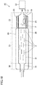
- Carbon nanotube manufacturing apparatus 10 can include: a tubular carbon nanotube growing unit (hereinafter also referred to as a CNT growing unit) 21; a gas supplying unit 22 that supplies a carbon-containing gas into CNT growing unit 21 from one end of CNT growing unit 21 (in Fig. 18 , a right end thereof); a catalyst supplying unit 23 that supplies catalyst particles P into CNT growing unit 21; and a carbon nanotube drawing unit (hereinafter also referred to as a CNT drawing unit) 30 that is disposed at the other end of CNT growing unit 21 (in Fig. 18 , a left end thereof) and draws a carbon nanotube obtained in CNT growing unit 21.
- CNT growing unit 21, CNT drawing unit 30, and catalyst supplying unit 23 include an uninterrupted reactor tube 31, and CNTs are manufactured inside reactor tube 31.
- carbon nanotubes are grown from catalyst particles by supplying a carbon-containing gas to the catalyst particles in a suspended state.
- the CNT has a length of 20 ⁇ m or less.
- the growing step is performed inside CNT growing unit 21.
- the growing step is preferably performed at a temperature of 800°C or more and 1200°C or less. If the temperature is less than 800°C, CNTs tend to be grown at a slower rate. On the other hand, when the temperature exceeds 1200°C, content of impurity carbon tends to increase.
- the growing step is performed under a condition in temperature of more preferably 900°C or more and 1150°C or less, and still more preferably 950°C or more and 1050°C or less.
- catalyst particles P examples include iron, nickel, cobalt, molybdenum, gold, silver, copper, palladium, and platinum.
- iron is preferably used from the viewpoint of mass production of elongate CNTs.
- the carbon-containing gas is supplied from gas supplying unit 22 to CNT growing unit 21 via catalyst supplying unit 23.
- a reducing gas such as hydrocarbon gas is used.
- a carbon-containing gas for example, a gaseous mixture of methane and argon, a gaseous mixture of ethylene and argon, a gaseous mixture of ethanol and argon, or the like can be used.
- the carbon-containing gas preferably includes carbon disulfide (CS 2 ) as an assistive catalyst.
- the lower limit for the average flow velocity in the CNT growing unit of the carbon-containing gas supplied from gas supplying unit 22 is 0.05 cm/sec, preferably 0.10 cm/sec, and more preferably 0.20 cm/sec.
- the upper limit for the average flow velocity in CNT growing unit 21 is preferably 10.0 cm/sec, more preferably 5.0 cm/sec. If the average flow velocity of the carbon-containing gas in CNT growing unit 21 is less than the lower limit, a carbon source gas supplied to catalyst particles P is insufficiently supplied, and carbon nanotubes formed between catalyst particles P tend to grow stagnantly.
- the lower limit for the Reynolds number of the flow in CNT growing unit 21 of the carbon-containing gas supplied from gas supplying unit 22 is preferably 0.01, and more preferably 0.05.
- the upper limit for the Reynolds number is 1000, preferably 100, and more preferably 10. If the Reynolds number is less than the lower limit, the apparatus is excessively restricted in design, which may make carbon nanotube assembled wire manufacturing apparatus 20 unnecessarily expensive and tends to unnecessarily lower efficiency of manufacturing carbon nanotubes. A Reynolds number exceeding the upper limit tends to disturb flow of the carbon-containing gas and inhibit production of carbon nanotubes between catalyst particles P.
- the length of the CNT obtained through the growing step is preferably 0.1 ⁇ m or more and 20 ⁇ m or less. If the length of the CNT obtained through the growing step is less than 0.1 ⁇ m, adjacent CNTs would not be oriented in the longitudinal direction and instead entangled, and tend to form secondary particles. On the other hand, when the length of the CNT exceeds 20 ⁇ m, a period of time before a drawing step is performed is increased, which tends to unnecessarily decrease efficiency of manufacturing the carbon nanotube.
- the length of the CNT obtained through the growing step is more preferably 0.5 ⁇ m or more and 15 ⁇ m or less, and still more preferably 1 ⁇ m or more and 10 ⁇ m or less. The length of the CNT can be measured through observation with a scanning electron microscope.
- the drawing step is performed inside CNT drawing unit 30.
- the carbon nanotubes are preferably oriented and drawn in a direction along the flow of the carbon-containing gas. According to this, the carbon nanotube is not easily bent, and a linear carbon nanotube having tube portion T composed only of a six-membered ring of carbon can be obtained.
- the carbon nanotube consisting of a six-membered ring of carbon is resistant to deterioration and can thus maintain quality.
- the tensile force is preferably applied to a plurality of carbon nanotubes by varying the carbon-containing gas in flow velocity. For example, by making an average flow velocity of the carbon-containing gas on the downstream side larger than that of the carbon-containing gas on the upstream side, a tensile force can be applied to the CNT in a direction toward the downstream side.
- a tensile force acts on an end of the carbon nanotube, the carbon nanotube is pulled while extending from catalyst particle P, and thus drawn in the longitudinal direction while it is plastically deformed and reduced in diameter.
- a hollow portion which passes the carbon-containing gas is formed to have a cross section smaller in area on the downstream side of the carbon-containing gas than the upstream side of the carbon-containing gas.
- a hollow portion in the CNT drawing unit (corresponding to a downstream side) passing the carbon-containing gas may have a cross section smaller in area than a hollow portion in the CNT growing unit (corresponding to an upstream side) passing the carbon-containing gas
- a hollow portion which passes the carbon-containing gas may be formed to have a cross section smaller in area on the downstream side of the carbon-containing gas than the upstream side of the carbon-containing gas. This generates an acceleration field in the vicinity of a region in which the hollow portion has a cross section reduced in area, and provides the carbon-containing gas with a faster flow velocity.
- the CNT drawing unit preferably has the hollow portion with an area in cross section of 0.0001% or more and 35% or less, more preferably 0.001% or more and 35% or less, still more preferably 0.005% or more and 20% or less, and still more preferably 0.01% or more and 5% or less of that in cross section of the hollow portion of the CNT growing unit.
- the area in cross section of the hollow portion of the CNT drawing unit is larger than 35% of the area in cross section of the hollow portion of the CNT growing unit, the acceleration field tends to be less likely generated.
- the area in cross section of the hollow portion of the CNT drawing unit is less than 0.0001% of the area in cross section of the hollow portion of the CNT growing unit, the CNT tends clog.
- the area in cross section of the hollow portion of the CNT growing unit is fixed from the upstream side to the downstream side except for a portion of both ends thereof.
- the area in cross section of the hollow portion of the CNT drawing unit means an area in cross section of a single hollow portion.
- the area in cross section of the hollow portion of the CNT drawing unit is fixed from the upstream side to the downstream side except for a portion of both ends thereof.
- an area in cross section being fixed means that the area in cross section has a maximum value and a minimum value with an average value falling within ⁇ 5%.
- the area in cross section of the hollow portion of the CNT drawing unit is 1% or less of the area in cross section of the CNT growing unit, there may be a high possibility that CNTs are assembled together to form a CNT assembled wire. Therefore, when it is desired to collect a larger amount of single CNTs, the area in cross section of the hollow portion of the CNT drawing unit is preferably larger than 1% and 35% or less of the area in cross section of the CNT growing unit.
- the area in cross section of the CNT growing unit can for example be 70 mm 2 or more and 7000 mm 2 or less.
- the area in cross section of the CNT drawing unit can for example be 0.005 mm 2 or more and 50 mm 2 or less.
- the area in cross section of the CNT drawing unit is 4 mm 2 or less, there may be a high possibility that CNTs are assembled together to form a CNT assembled wire. Therefore, when it is desired to collect a larger amount of single CNTs, the area in cross section of the CNT drawing unit is preferably larger than 4 mm 2 and 50 mm 2 or less.
- the area in cross section of the hollow portion on the downstream side of the carbon-containing gas is preferably 0.001% or more and 35% or less, more preferably 0.005% or more and 20% or less, and still more preferably 0.010% or more and 5% or less of the area in cross section of the hollow portion on the upstream side of the carbon-containing gas.
- the acceleration field tends to be less likely generated.
- the area in cross section of the hollow portion on the downstream side is less than 0.001% of the area in cross section of the hollow portion on the upstream side, CNTs tend to clog.
- the area in cross section of the hollow portion on the downstream side can for example be 0.005 mm 2 or more and 50 mm 2 or less.
- the area in cross section on the upstream side can for example be 70 mm 2 or more and 7000 mm 2 or less.
- the lower limit for the average flow velocity of the carbon-containing gas in CNT drawing unit 30 is 0.05 cm/sec, preferably 0.2 cm/sec, and more preferably 1 cm/sec.
- the upper limit for the average flow velocity in CNT drawing unit 30 is preferably 10 cm/sec, more preferably 5 cm/sec.
- the lower limit for the Reynolds number of the flow of the carbon-containing gas in CNT drawing unit 30 is preferably 0.01, and more preferably 0.05.
- the upper limit for the Reynolds number is 1000, preferably 100, and more preferably 10. If the Reynolds number is less than 0.01, the apparatus is excessively restricted in design, which may make carbon nanotube manufacturing apparatus 10 unnecessarily expensive and tends to unnecessarily lower efficiency of manufacturing carbon nanotubes. A Reynolds number exceeding 1000 tends to disturb flow of the carbon-containing gas and inhibit drawing of carbon nanotubes between catalyst particles P.
- the tensile force is preferably applied to a carbon nanotube by using a magnetic field.
- an electric wire can be disposed in the form of a coil surrounding a reactor tube and a current can be passed through the electric wire to generate a magnetic line of force inside the reactor tube in a direction along the central axis of the reactor tube to apply tensile force derived from a magnetic field to a CNT.
- a magnetic field when drawing a CNT, a magnetic force directly acts on metal included in the CNT, and the CNT can thus be oriented and drawn in a direction along a magnetic line of force passing inside the reactor tube.
- the tensile force is preferably applied to a carbon nanotube by using an electric field.
- a positive electrode made of a conductive material is disposed on a downstream side of the carbon-containing gas and a negative electrode made of a conductive material is disposed on an upstream side of the carbon-containing gas, and an electric field along the central axis of the reactor tube is generated to allow tensile force derived from the electric field to be applied to a CNT.
- electrostatic force acts directly on each one of CNTs, and the CNTs can be oriented and drawn in a direction along an electric line of force.
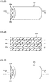
- the carbon nanotube produced through the drawing step can include a tubular tube portion T and conical cone portions C which expand continuously in diameter from ends of the tube portion, as shown in Fig. 6 .
- a carbon nanotube formed through vapor deposition is stretched by tensile force simultaneously with the formation thereof to thereby convert some hexagonal cells of the carbon nanotube into pentagonal cells to form the conical cone portion, and convert the pentagonal cells again into hexagonal cells to form the tube portion which is a carbon nanotube with a smaller diameter.
- a carbon nanotube grown on catalyst particle P is grown while being stretched by using tensile force, and the tube portion can be formed at an extremely larger rate than the carbon nanotube is grown on catalyst particle P.
- a long carbon nanotube can be formed in a relatively short period of time.
- a sufficiently long carbon nanotube can be formed even if a condition allowing the carbon nanotube to be continuously grown on catalyst particle P can only be maintained for a short period of time.
- the carbon nanotube in the drawing step, by causing tensile force to act on a carbon nanotube on catalyst particle P, the carbon nanotube is less likely to be curved, and thus a linear carbon nanotube composed of a cylindrical body formed of a sheet with tube portion T consisting of a six-membered ring of carbon can be obtained.
- the carbon nanotube consisting of a six-membered ring of carbon is resistant to deterioration and can thus maintain quality.
- the length of the CNT obtained through the drawing step is preferably 10 ⁇ m or more, and further preferably 100 ⁇ m or more.
- the length of the carbon nanotube is 100 ⁇ m or more, such a length is suitable from the viewpoint of producing the CNT assembled wire.
- the upper limit value for the length of the carbon nanotube is not particularly limited, it is preferably 600 mm or less from the viewpoint of manufacturing.
- the length of the CNT can be measured through observation with a scanning electron microscope.
- a carbon nanotube manufactured in the method for manufacturing a carbon nanotube in accordance with Embodiment 1 will now be described with reference to Fig. 6 .
- the carbon nanotube can be a CNT of a known structure.
- Examples of the carbon nanotube that can be used include a single-layer carbon nanotube in which only a single carbon layer (graphene) has a cylindrical shape, a double-layer carbon nanotube or a multilayer carbon nanotube in which a stacked body of a plurality of carbon layers has a cylindrical shape, and the like.
- carbon nanotube 2 may have a tube portion T having one or both ends with a catalyst P, which is used in producing the carbon nanotube, adhering thereto.
- a cone portion C made of a conical graphene may be formed at one end or both ends of tube portion T of carbon nanotube 2.
- the length of the carbon nanotube can be selected as appropriate depending on the application.
- the length of the carbon nanotube is preferably 10 ⁇ m or more, and further preferably 100 ⁇ m or more, for example. In particular, when the length of the carbon nanotube is 100 ⁇ m or more, such a length is suitable from the viewpoint of producing the CNT assembled wire.
- the upper limit value for the length of the carbon nanotube is not particularly limited, it is preferably 600 mm or less from the viewpoint of manufacturing.
- the length of the CNT can be measured through observation with a scanning electron microscope.
- the diameter of the carbon nanotube is preferably 0.6 nm or more and 20 nm or less, and further preferably 1 nm or more and 10 nm or less. In particular, when the diameter of the carbon nanotube is 1 nm or more and 10 nm or less, such a diameter is suitable from the viewpoint of heat resistance under oxidizing conditions.
- the diameter of the carbon nanotube is measured is the same as has been described in comparing a distance between CNTs and an average diameter of the CNTs, and accordingly, will not be described repeatedly.
- the CNT includes a cone portion at one end or both ends thereof, the diameter is measured at a location other than the cone portion.
- the carbon nanotube preferably has a D/G ratio of 0.1 or less, the D/G ratio being a ratio of a peak intensity of a D band to a peak intensity of a G band in a Raman spectroscopic analysis with a wavelength of 532 nm.
- the G band is a peak originating in the CNT seen in the vicinity of a Raman shift of 1590 cm -1 in a Raman spectrum obtained through Raman spectroscopy.
- the D band is a peak originating in amorphous carbon or a defect in graphite or the CNT seen in the vicinity of a Raman shift of 1350 cm -1 in the Raman spectrum obtained through Raman spectroscopy. Therefore, as the D/G ratio has a smaller value, the carbon nanotube has a higher crystallinity, and the carbon nanotube contains a smaller amount of amorphous carbon or defective graphite.
- a CNT having a D/G ratio of 0.1 or less has little amorphous carbon or defective graphite, and hence has high crystallinity. Thus, the CNT can have high tensile strength and high electrical conductivity. If the D/G ratio of the CNT exceeds 0.1, the CNT may be unable to have sufficient tensile strength and high electrical conductivity.
- the D/G ratio is preferably 0.1 or less, and more preferably 0.01 or less. Although the lower limit value for the D/G ratio is not particularly limited, it can be 0 or more, for example.
- the D/G ratio of the carbon nanotube is a value measured in the following method.
- the carbon nanotube is subjected to Raman spectroscopic analysis under the following conditions to obtain a Raman spectrum (hereinafter also referred to as the Raman spectrum of the CNT assembled wire).
- a D/G ratio is calculated from a peak intensity of the D band and a peak intensity of the G band in the Raman spectrum of the CNT.
- Carbon nanotube manufacturing apparatus 10 shown in Fig. 18 can include: a tubular carbon nanotube growing unit (hereinafter also referred to as a CNT growing unit) 21; a gas supplying unit 22 that supplies a carbon-containing gas into CNT growing unit 21 from one end of CNT growing unit 21 (in Fig. 18 , a right end thereof); a catalyst supplying unit 23 that supplies catalyst particles P into CNT growing unit 21; and a carbon nanotube drawing unit (hereinafter also referred to as a CNT drawing unit) 30 that is disposed at the other end of CNT growing unit 21 (in Fig. 18 , a left end thereof) and draws a carbon nanotube obtained in CNT growing unit 21.
- CNT growing unit 21, CNT drawing unit 30, and catalyst supplying unit 23 include uninterrupted reactor tube 31, and CNTs are manufactured inside reactor tube 31.
- Carbon nanotube growing unit 21 is in the form of a tube that is a quartz tube for example.
- carbon nanotubes 2 are formed on catalyst particles P by using a carbon-containing gas.
- Carbon nanotube growing unit 21 is disposed in electric furnace 28 and heated by a heater (not shown).
- the internal temperature in CNT growing unit 21 is preferably 800°C or more and 1200°C or less.
- the carbon-containing gas may be heated previously and then supplied from gas supplying unit 22 into CNT growing unit 21, or the carbon-containing gas may be heated in CNT growing unit 21.
- Gas supplying unit 22 supplies the carbon-containing gas to CNT growing unit 21 at one end of carbon nanotube growing unit 21 (in Fig. 18 , a right end thereof).
- Gas supplying unit 22 can include a gas cylinder (not shown) and a flow control valve (not shown).
- the type of the carbon-containing gas supplied from gas supplying unit 22, the average flow velocity thereof in the CNT growing unit, and the Reynolds number of the flow thereof in the CNT growing unit can be the same as those described in Embodiment 1, and accordingly, will not be described repeatedly.
- gas supplying unit 22 can repeatedly change the amount of the carbon-containing gas to be supplied to CNT growing unit 21. This can increase/decrease the flow velocity of the carbon-containing gas in CNT growing unit 21, which can help separating catalyst particles integrated together and thus increase the number of carbon nanotubes to be obtained.
- Catalyst supplying unit 23 may be disposed between gas supplying unit 22 and CNT growing unit 21.
- a catalyst holder 26 for holding catalyst 27 is disposed inside catalyst supplying unit 23.
- Catalyst supplying unit 23 is provided with a heater 25. That is, catalyst supplying unit 23 is heated by a heater.
- Catalyst supplying unit 23 supplies a flow of the carbon-containing gas with catalyst 27 disintegrated by wind pressure of the carbon-containing gas and thus divided into a plurality of catalyst particles P.
- Catalyst supplying unit 23 supplies a flow of the carbon-containing gas with catalyst 27 disintegrated by wind pressure of the carbon-containing gas and thus divided into a plurality of catalyst particles P.
- Examples of catalyst 27 can include ferrocene (Fe(C 5 H 5 ) 2 ), nickelocene (Ni(C 5 H 5 ) 2 ), cobaltocene (Co(C 5 H 5 ) 2 , etc.), and the like.
- ferrocene is particularly preferable as it is excellent in disintegrability and catalysis. It is believed that, when ferrocene is heated to a high temperature in catalyst supplying unit 23 and exposed to the carbon-containing gas, it forms iron carbide (Fe 3 C) on a surface thereof due to carburization, and is thus disintegratable from the surface to release fine catalyst particles P successively. In this case, a major ingredient of catalyst particles P formed will be iron carbide or iron.
- the lower limit for the average diameter of catalyst particles P is preferably 30 nm, more preferably 40 nm, and further preferably 50 nm.
- the upper limit for the average diameter of catalyst particles P is preferably 1000 ⁇ m, more preferably 100 ⁇ m, and further preferably 10 ⁇ m. If the average diameter of catalyst particles P is less than the lower limit, carbon nanotubes formed from the catalyst particles tend to have a small diameter and a low drawing ratio, and hence insufficient length. On the contrary, if the average diameter of the catalyst particles exceeds the upper limit, it tends to be difficult to draw carbon nanotubes formed by the catalyst particles.
- Carbon nanotube drawing unit 30 is disposed at an end of CNT growing unit 21 opposite to gas supplying unit 23. That is, CNT drawing unit 30 is disposed downstream of CNT growing unit 21 as seen in the direction of the flow of the carbon-containing gas. In CNT drawing unit 30, a carbon nanotube is drawn.
- the CNT drawing unit any structure can be used as long as it can apply tensile force to a carbon nanotube in a suspended state and thus draw the carbon nanotube.
- the CNT drawing unit may comprise a cylindrical structure having a smaller diameter than the CNT growing unit.
- the CNT drawing unit can be formed of a honeycomb structure, a straight-tube-type narrow tube structure, or the like.
- the area in cross section of the hollow portion of the CNT drawing unit is preferably 0.01% or more, more preferably 0.005% or more and 20% or less, and still more preferably 0.01% or more and 5% or less of the area in cross section of the CNT growing unit.
- the area in cross section of the CNT drawing unit in this case can for example be 0.005 mm 2 or more and 50 mm 2 or less.
- the length of the cylindrical structure in the direction along the through hole is preferably 1 mm or more and 1 m or less, more preferably 10 mm or more and 50 cm or less, and still more preferably 15 mm or more and 10 cm or less.
- the length of the cylindrical structure in the direction along the through hole is less than 1 mm, CNTs suspended in a vapor phase are insufficiently accelerated and a growth promoting effect tends to be suppressed.
- the length of the cylindrical structure in the direction along the through-hole exceeds 1 m, an amount of CNTs deposited on the internal wall of the through hole is increased, and it tends to be difficult to collect the CNTs.
- the length of the CNT drawing unit exceeds 20 mm, there may be a high possibility that CNTs are assembled together to form a CNT assembled wire. Therefore, when it is desired to collect a larger amount of single CNTs, the length of the CNT drawing unit is preferably 1 mm or more and less than 20 mm.
- the honeycomb structure is disposed in the carbon nanotube assembled wire manufacturing apparatus such that the through holes have a longitudinal direction along the flow of the carbon-containing gas.
- a honeycomb structure means a porous body having a large number of narrow tubular through holes.
- each through hole preferably has an area in cross section of 0.005 mm 2 or more, preferably 0.01 mm 2 or more, more preferably 0.05 mm 2 or more, still more preferably 0.1 mm 2 or more, and still more preferably 0.5 mm 2 or more.
- the area in cross section of the through hole is less than 0.005 mm 2 , CNTs tend to clog the through hole.
- the upper limit for the area in cross section of the through hole is preferably 100 mm 2 , more preferably 50 mm 2 , and still more preferably 10 mm 2 , for example.
- the area in cross section of the through hole is fixed from the upstream side to the downstream side.
- an area in cross section being fixed means that the area in cross section has a maximum value and a minimum value with an average value falling within ⁇ 5%.
- the area in cross section of the CNT drawing unit is 4 mm 2 or less, there may be a high possibility that CNTs are assembled together to form a CNT assembled wire. Therefore, when it is desired to collect a larger amount of single CNTs, the area in cross section of the CNT drawing unit is preferably larger than 4 mm 2 and 100 mm 2 or less.
- the honeycomb structure when the CNT drawing unit is formed of a honeycomb structure, the honeycomb structure, as seen in a direction along the through hole (i.e., the longitudinal direction), preferably has a length of 1 mm or more and 1 m or less, more preferably 10 mm or more and 50 cm or less, and still more preferably 15 mm or more and 10 cm or less.
- the honeycomb structure has a length of less than 1 mm in the direction along the through hole, the CNTs suspended in a vapor phase are insufficiently accelerated and a growth promoting effect tends to be suppressed.
- the honeycomb structure has a length exceeding 1 m in the direction along the through hole, an amount of CNTs deposited on the internal wall of the through hole is increased, and it tends to be difficult to collect the CNTs.
- the length of the CNT drawing unit exceeds 20 mm, there may be a high possibility that CNTs are assembled together to form a CNT assembled wire. Therefore, when it is desired to collect a larger amount of single CNTs, the length of the CNT drawing unit is preferably 1 mm or more and less than 20 mm.
- the honeycomb structure can be made of a ceramic material (alumina, zirconia, aluminum nitride, silicon carbide, silicon nitride, forsterite, steatite, cordierite, mullite, ferrite, and the like), quartz glass, glass, metals, graphite.
- a ceramic material alumina, zirconia, aluminum nitride, silicon carbide, silicon nitride, forsterite, steatite, cordierite, mullite, ferrite, and the like
- quartz glass glass, metals, graphite.
- the ceramic material is preferable in view of heat resistance and durability required in manufacturing CNTs.
- the CNT manufacturing apparatus can include in addition to the above configuration a magnetic field generating unit that generates a magnetic field.
- a magnetic field generating unit that generates a magnetic field.
- an electric wire can be provided in the form of a coil surrounding a reactor tube.
- a magnetic line of force can be generated inside the reactor tube in a direction along the central axis of the reactor tube to apply tensile force derived from a magnetic field to a CNT.
- the CNT manufacturing apparatus can include in addition to the above configuration a magnetic field generating unit that generates a magnetic field.
- a positive electrode made of a conductive material can be disposed on a downstream side of the carbon-containing gas, and a negative electrode made of a conductive material can be disposed on an upstream side of the carbon-containing gas.
- an electric field can be generated along the central axis of the reactor tube, and a tensile force derived from the electric field can be applied to the CNT.
- a method for manufacturing a carbon nanotube assembled wire includes: supplying a carbon-containing gas to a plurality of suspended catalyst particles to grow one or more carbon nanotubes from each of the plurality of catalyst particles (hereinafter also referred to as a growing step); applying a tensile force to a plurality of suspended carbon nanotubes to draw the plurality of carbon nanotubes (hereinafter also referred to as a drawing step); and orienting and assembling the plurality of suspended carbon nanotubes together in a direction along the flow of the carbon-containing gas to obtain a carbon nanotube assembled wire (hereinafter also referred to as an assembling step).
- Carbon nanotube assembled wire can be manufactured for example in a carbon nanotube assembled wire manufacturing apparatus shown in Fig. 14 .
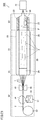
- Carbon nanotube assembled wire manufacturing apparatus 20 can include: a tubular carbon nanotube growing unit (hereinafter also referred to as a CNT growing unit) 21; a gas supplying unit 22 that supplies a carbon-containing gas into CNT growing unit 21 from one end of CNT growing unit 21 (in Fig. 14 , a right end thereof); a catalyst supplying unit 23 that supplies catalyst particles P into CNT growing unit 21; and a carbon nanotube assembling unit 24 (hereinafter also referred to as a CNT assembling unit) that is disposed at the other end of CNT growing unit 21 (in Fig. 14 , a left end thereof) and orients and assembles a plurality of carbon nanotubes that are obtained in CNT growing unit 21 together in a direction along a flow of the carbon-containing gas.
- a tubular carbon nanotube growing unit hereinafter also referred to as a CNT growing unit 21
- one or more carbon nanotubes are grown from catalyst particles by supplying a carbon-containing gas to the catalyst particles in a suspended state. How the growing step is specifically be performed will not be described as it is the same as that described in Embodiment 1.
- the length of the CNT obtained through the growing step is preferably 0.1 ⁇ m or more and 20 ⁇ m or less. If the length of the CNT obtained through the growing step is less than 0.1 ⁇ m, adjacent CNTs would not be oriented in the longitudinal direction and instead entangled, and tend to form secondary particles. On the other hand, when the length of the CNT exceeds 20 ⁇ m, a period of time before a drawing step is performed is increased, which tends to unnecessarily decrease efficiency of manufacturing the carbon nanotube.
- the length of the CNT obtained through the growing step is more preferably 0.5 ⁇ m or more and 15 ⁇ m or less, and still more preferably 1 ⁇ m or more and 10 ⁇ m or less. The length of the CNT can be measured through observation with a scanning electron microscope.
- a tensile force is applied to the plurality of carbon nanotubes in the suspended state that are obtained in the growing step to draw the plurality of carbon nanotubes.
- the drawing step is performed inside CNT growing unit 21 and CNT assembling unit 24, or inside CNT assembling unit 24.
- the drawing step is preferably performed in CNT growing unit 21 on a downstream side of the carbon-containing gas, that is, on a side closer to the CNT assembling unit.
- the tensile force is preferably applied to a plurality of carbon nanotubes by varying the carbon-containing gas in flow velocity. For example, by making an average flow velocity of the carbon-containing gas on the downstream side larger than that of the carbon-containing gas on the upstream side, a tensile force can be applied to the CNT in a direction toward the downstream side.
- a tensile force acts on an end of the carbon nanotube, the carbon nanotube is pulled while extending from catalyst particle P, and thus drawn in the longitudinal direction while it is plastically deformed and reduced in diameter.
- the plurality of carbon nanotubes are preferably oriented in a direction along the flow of the carbon-containing gas and thus drawn. According to this, it is believed that the carbon nanotube is not easily bent, and a linear carbon nanotube having tube portion T composed only of a six-membered ring of carbon can be obtained.
- the carbon nanotube consisting of a six-membered ring of carbon is resistant to deterioration and can thus maintain quality.
- the carbon-containing gas on the downstream side preferably has an average flow velocity of 0.051 cm/sec or more and 10.001 cm/sec or less, and more preferably 0.201 cm/sec or more and 5.001 cm/sec or less.
- the carbon-containing gas on the downstream side has an average flow velocity of less than 0.051 cm/sec, the carbon nanotube tends to be drawn insufficiently faster than it is grown.
- the carbon-containing gas on the downstream side has an average flow velocity exceeding 10.001 cm/sec, this tends to detach carbon nanotubes from catalyst particles P, which stops growth of the carbon nanotubes and consequently inhibits formation of carbon nanotubes.
- the carbon-containing gas on the upstream side preferably has an average flow velocity of 0.050 cm/sec or more and 10.000 cm/sec or less, and more preferably 0.200 cm/sec or more and 5.000 cm/sec or less. If the carbon-containing gas on the upstream side has an average flow velocity of less than 0.050 cm/sec, insufficient wind pressure is provided, and carbon nanotubes formed between catalyst particles P tend to grow stagnantly. On the contrary, if the carbon-containing gas on the upstream side has an average flow velocity exceeding 10.000 cm/sec, this tends to detach carbon nanotubes from catalyst particles P, which stops growth of the carbon nanotubes and consequently inhibits formation of carbon nanotubes.
- a hollow portion which passes the carbon-containing gas is formed to have a cross section smaller in area on the downstream side of the carbon-containing gas than the upstream side of the carbon-containing gas.
- a hollow portion which passes the carbon-containing gas may be formed to have a cross section smaller in area on the downstream side of the carbon-containing gas than the upstream side of the carbon-containing gas, and (ii) a hollow portion in the CNT assembling unit (corresponding to the downstream side) passing the carbon-containing gas may have a cross section smaller in area than a hollow portion in the CNT growing unit (corresponding to the upstream side) passing the carbon-containing gas.
- the area in cross section of the hollow portion on the downstream side of the carbon-containing gas is preferably 0.001% or more and 35% or less, more preferably 0.005% or more and 20% or less, and still more preferably 0.01% or more and 5% or less of the area in cross section of the hollow portion on the upstream side of the carbon-containing gas.
- the acceleration field tends to be less likely generated.
- the area in cross section of the hollow portion on the downstream side is less than 0.001% of the area in cross section of the hollow portion on the upstream side, CNTs tend to clog.
- Fig. 15 is a view showing the vicinity of a magnetic field generating unit 24a of a CNT assembled wire manufacturing apparatus 20a. As shown in Fig.
- an electric wire 301 can be disposed in the form of a coil surrounding reactor tube 31 and a current can be passed through the electric wire to generate magnetic line of force 32 inside reactor tube 31 in a direction along the central axis of reactor tube 31 to apply tensile force derived from a magnetic field to a CNT.
- a magnetic field when drawing a CNT, a magnetic force directly acts on metal included in the CNT, and the CNT can be oriented and drawn in a direction along magnetic line of force 32 passing inside the reactor tube.
- Fig. 15 shows the magnetic field drawing and also assembling CNTs together
- the CNTs may not be drawn and assembled together simultaneously. That is, the magnetic field may only draw CNTs and may not assemble CNTs together.
- electric wire 301 is disposed in CNT growing unit 21 on a downstream side of the carbon-containing gas to generate a magnetic field in CNT growing unit 21.
- Fig. 16 is a diagram showing the vicinity of an electric field generating unit 24b of a CNT assembled wire manufacturing apparatus 20b. As shown in Fig.
- a positive electrode 33 made of a conductive material is disposed on a downstream side of the carbon-containing gas and a negative electrode 34 made of a conductive material is disposed on an upstream side of the carbon-containing gas, and an electric field along the central axis of reactor tube 31 is generated to allow tensile force derived from the electric field to be applied to a CNT.
- electrostatic force acts directly on the CNT and metal included in the CNT, and the CNT can be oriented in a direction along an electric line of force and thus drawn.
- Fig. 16 shows the electric field drawing and also assembling CNTs together
- the CNTs may not be drawn and assembled together simultaneously. That is, the electric field may only draw CNTs and may not assemble CNTs together.
- positive electrode 33 and negative electrode 34 are disposed in CNT growing unit 21 on a downstream side of the carbon-containing gas to generate an electric field in CNT growing unit 21.
- the carbon nanotube produced through the drawing step can include a tubular tube portion T and conical cone portions C which expand continuously in diameter from ends of the tube portion, as shown in Fig. 6 .
- a carbon nanotube formed through vapor deposition is stretched by tensile force simultaneously with the formation thereof to thereby convert some hexagonal cells of the carbon nanotube into pentagonal cells to form the conical cone portion, and convert the pentagonal cells again into hexagonal cells to form the tube portion which is a carbon nanotube with a smaller diameter.
- a carbon nanotube grown on catalyst particle P is grown while being stretched by using tensile force, and the tube portion can be formed at an extremely larger rate than the carbon nanotube is grown on catalyst particle P.
- a long carbon nanotube can be formed in a relatively short period of time.
- a sufficiently long carbon nanotube can be formed even if a condition allowing the carbon nanotube to be continuously grown on catalyst particle P can only be maintained for a short period of time.
- the carbon nanotube in the drawing step, by causing tensile force to act on a carbon nanotube on catalyst particle P, the carbon nanotube is less likely to be curved, and thus a linear carbon nanotube composed of a cylindrical body formed of a sheet with tube portion T consisting of a six-membered ring of carbon can be obtained.
- the carbon nanotube consisting of a six-membered ring of carbon is resistant to deterioration and can thus maintain quality.
- the length of the CNT obtained through the drawing step is preferably 10 ⁇ m or more, and further preferably 100 ⁇ m or more.
- the length of the carbon nanotube is 100 ⁇ m or more, such a length is suitable from the viewpoint of producing the CNT assembled wire.
- the upper limit value for the length of the carbon nanotube is not particularly limited, it is preferably 600 mm or less from the viewpoint of manufacturing.
- the length of the CNT can be measured through observation with a scanning electron microscope.
- the plurality of carbon nanotubes in the suspended state are oriented and assembled together in a direction along the flow of the carbon-containing gas to obtain a carbon nanotube assembled wire.
- the assembling step is performed inside CNT assembling unit 24.
- a hollow portion in the CNT assembling unit passing the carbon-containing gas may have a cross section smaller in area than a hollow portion in the CNT growing and drawing units passing the carbon-containing gas.
- the CNT assembling unit may have a honeycomb structure, and the honeycomb structure may have through holes arranged to have a longitudinal direction along the flow of the carbon-containing gas.
- the honeycomb structure means a porous body having a large number of narrow tubular through holes, as shown in Fig. 14 by a honeycomb structure 29.
- an area in cross section of each through hole is preferably 0.005 mm 2 or more and 100 mm 2 or less, more preferably 0.01 mm 2 or more and 100 mm 2 or less, still more preferably 0.05 mm 2 or more and 100 mm 2 or less, still more preferably 0.1 mm 2 or more and 50 mm 2 or less, and still more preferably 0.5 mm 2 or more and 10 mm 2 or less.
- the area in cross section of the through hole is less than 0.005 mm 2 , CNTs tend to clog the through hole.
- the through hole has an area in cross section exceeding 100 mm 2 , CNTs insufficiently approach one another, and tend to be unable to form an assembly.
- the area in cross section of the CNT assembling unit is more than 4 mm 2 , CNTs are insufficiently assembled together, and there is a possibility that single CNTs may exist together with a CNT assembled wire. Therefore, when it is desired to collect a larger amount of CNT assembled wire, the area in cross section of the CNT assembling unit is preferably 0.005 mm 2 or more and 4 mm 2 or less, and more preferably 0.01 mm 2 or more and 4 mm 2 or less.
- the honeycomb structure when the CNT assembling unit is formed of a honeycomb structure, the honeycomb structure, as seen in a direction along the through hole (i.e., the longitudinal direction), preferably has a length of 1 mm or more and 1 m or less, more preferably 10 mm or more and 50 cm or less, and still more preferably 15 mm or more and 10 cm or less.
- the honeycomb structure has a length of less than 1 mm in the direction along the through hole, the CNTs suspended in a vapor phase are insufficiently accelerated and a growth promoting effect tends to be suppressed.
- the honeycomb structure has a length exceeding 1 m in the direction along the through hole, an amount of CNTs deposited on the internal wall of the through hole is increased, and it tends to be difficult to collect the CNTs.
- the length of the CNT drawing unit is less than 20 mm, CNTs are insufficiently assembled together, and there is a possibility that single CNTs may exist together with a CNT assembled wire. Therefore, when it is desired to collect a larger amount of CNT assembled wire, the length of the CNT drawing unit is preferably 20 mm or more and 1 m or less.
- the carbon-containing gas in the CNT assembling unit preferably has an average flow velocity of 0.05 cm/sec or more and 10 cm/sec or less, and more preferably 0.2 cm/sec or more and 5 cm/sec or less.
- the average flow velocity of the carbon-containing gas is less than 0.05 cm/sec, a thin-film non-oriented CNT tends to be obtained.
- the average flow velocity of the carbon-containing gas exceeds 10 cm/sec, the carbon-containing gas tends to arrive at the CNT assembling unit in an unreacted state and cause an incomplete decomposition reaction, resulting in adhesion of tar.
- the drawing step is followed by the assembling step, the drawing step and the assembling step may be performed simultaneously. Furthermore, the drawing step may be followed by an additional drawing step and an assembling step performed simultaneously. For example, when the honeycomb structure is used as the CNT assembling unit, drawing CNTs and assembling the CNTs are simultaneously performed in the through holes of the honeycomb structure.
- a carbon-containing gas can be supplied to the catalyst supplying unit, the CNT growing unit, and the CNT assembling unit continuously, and a CNT assembled wire can be continuously manufactured without limitation on length.
- the CNT assembled wire can be adjusted in length, as appropriate, by adjusting the flow rate of the carbon-containing gas, how long in time it is supplied, and the like.
- the length of the CNT assembled wire obtained through the assembling step is preferably 100 ⁇ m or more, more preferably 1000 ⁇ m or more, and further preferably 10000 ⁇ m or more.
- the upper limit value for the length of the CNT assembled wire is not particularly limited, it is preferably 1 m or less from the viewpoint of manufacturing.
- the length of the CNT assembled wire can be measured through observation with an optical microscope or visual observation.
- FIG. 14 is a diagram for illustrating a carbon nanotube assembled wire manufacturing apparatus in accordance with an embodiment of the present disclosure.
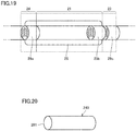
- Fig. 20 is an enlarged view of a second flow channel of the carbon nanotube assembling unit. In Fig. 20 , the right side is the upstream side, and the left side is the downstream side.
- a plurality of carbon nanotubes and the carbon-containing gas pass through a first flow channel
- the plurality of carbon nanotubes and the carbon-containing gas pass through one or more second flow channels located downstream of the first flow channel, with each second flow channel having an area in cross section smaller than the first flow channel.
- the first flow channel corresponds to the hollow portion of CNT growing unit 21
- the second flow channel corresponds to the hollow portion of CNT assembling unit 24 (that is, a through hole of honeycomb structure 29).
- a tensile force toward the downstream side can be applied to the carbon nanotubes.
- the carbon-containing gas located downstream of the one or more second flow channels is lower in temperature than the carbon-containing gas located upstream of the one or more second flow channels.
- CNTs are assembled together easily.
- the carbon-containing gas located upstream of the one or more second flow channels has a temperature of 800°C or more, and the carbon-containing gas located downstream of the one or more second flow channels has a temperature of 600°C or less.
- CNTs are assembled together easily.
- the temperature of the carbon-containing gas upstream of the one or more second flow channels is preferably 800°C or more and 1200°C or less, more preferably 900°C or more and 1150°C or less, and still more preferably 950°C or more and 1050°C or less.
- the temperature of the carbon-containing gas downstream of the one or more second flow channels is preferably 600°C or less, more preferably 500°C or less, and still more preferably 300°C or less. While the lower limit for the temperature of the carbon-containing gas downstream of the one or more second flow channels is not particularly limited, it can for example be 80°C. It is to be noted that exposing a CNT assembled wire having passed through the one or more second flow channels to a liquid of ethanol in the form of mist or the like to impregnate gaps between CNT filaments with the liquid, and subsequently evaporating the liquid at about 78°C can serve as an additional process to reduce the gaps between the CNT filaments to bond them together to achieve high density.
- the temperature of the carbon-containing gas in the one or more second flow channels is preferably lower at the downstream side than at the upstream side, and the temperature of the carbon-containing gas in the second flow channel at a downstream end is 600°C or less.
- the downstream end in the second flow channel corresponds to an outlet 291 on a downstream side of a second flow channel 240 (i.e. a through hole of the honeycomb structure) in Fig. 20 .
- the temperature of the carbon-containing gas in the second flow channel at the downstream end is more preferably 500°C or less, and still more preferably 300°C or less. While the lower limit for the temperature of the carbon-containing gas in the second flow channel at the downstream end is not particularly limited, it can for example be 80°C.
- a first region in which the temperature of the carbon-containing gas is 600°C or less is present in the second flow channel on the downstream side, and the length of the first region in the longitudinal direction of the second flow channel is 1 cm or more.
- CNTs are assembled together easily in the second flow channel.
- the length of the first region in the longitudinal direction of the second flow channel is preferably 1 cm or more, and more preferably 5 cm or more. While the upper limit for the length of the first region in the longitudinal direction of the second flow channel is not particularly limited, it is preferably 20 cm, for example.
- the area in cross section of each of the second flow channels is preferably 0.01 mm 2 or more and 4 mm 2 or less. Thus, the diameter of the CNT is reduced easily.
- the area in cross section of each of the second flow channels is more preferably 0.1 mm 2 or more and 2 mm 2 or less, and still more preferably 0.2 mm 2 or more and 1 mm 2 less.
- a ratio S1/S2 is 100 or more and 1000000 or less, where S1 is an area in cross section of the first flow channel and S2 is an area in cross section of each of the second flow channels.
- S1/S2 is more preferably 1000 or more and 100000 or less, and still more preferably 4000 or more and 40000 or less.
- the area in cross section of the first flow channel is fixed from the upstream side to the downstream side except for a portion of both ends thereof.
- the area in cross section of each of the second flow channels is fixed from the upstream side to the downstream side except for a portion of both ends thereof.
- an area in cross section being fixed means that the area in cross section has a maximum value and a minimum value with an average value falling within ⁇ 5%.
- the plurality of carbon nanotubes are reduced in diameter.
- the CNT assembled wire including CNTs of a smaller diameter can be obtained.
- the one or more second flow channels each have a length of 10 mm or more and 200 mm or less.
- the length of each of the second flow channels is more preferably 20 mm or more and 100 mm or less, and still more preferably 30 mm or more and 80 mm or less.
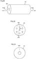
- Fig. 23 shows a honeycomb structure 29d including a plurality of second flow channels 240a.
- Fig. 24 is a cross section of the honeycomb structure of Fig. 23 taken along a line XXIV-XXIV.
- second flow channels 240a each have a shape of a through hole with a helical groove M1 in a periphery of the through hole.
- the gas in the second flow channel flows helically, so that a uniform twist angle is formed easily in the CNT assembled wire.
- a CNT assembled wire bundle formed by bundling such CNT assembled wires can also have a uniform twist angle.
- the CNT assembled wire bundle can have excellent mechanical strength.
- Fig. 33 shows a honeycomb structure 29g including a plurality of second flow channels 240d.
- Fig. 34 is a view of the honeycomb structure of Fig. 33 as seen in a direction indicated by an arrow XXXIV (or on an upstream side).
- Fig. 35 is a view of the honeycomb structure of Fig. 33 as seen in a direction indicated by an arrow XXXV (or on a downstream side).
- Fig. 36 is a cross section of the honeycomb structure of Fig. 33 taken along a line XXXVI-XXXVI.
- the area in cross section of each of second flow channels 240d is preferably smaller on the downstream side than on the upstream side.
- the area in cross section of the second flow channel means an area in a cross section with the second flow channel's longitudinal direction as a normal thereto.
- the area in cross section of the upstream side of the second flow channel is preferably 0.1 mm 2 or more and 100 mm 2 or less, and more preferably 0.5 mm 2 or more and 50 mm 2 or less.
- the area in cross section of the downstream side thereof is preferably 0.005 mm 2 or more and 10 mm 2 or less, and more preferably 0.01 mm 2 or more and 1 mm 2 or less.
- S2B/S2A which is a ratio of an area in cross section S2B on the downstream side of the second flow channel to an area in cross section S2A on the upstream side of the second flow channel, is preferably 0.00005 or more and 0.5 or less, and more preferably 0.0001 or more and 0.25 or less.
- Fig. 1 is a diagram for illustrating a carbon nanotube assembled wire (hereinafter also referred to as a CNT assembled wire) in accordance with an embodiment of the present disclosure.
- a carbon nanotube assembled wire 1 in accordance with the present embodiment includes a plurality of carbon nanotubes 2.
- the plurality of carbon nanotubes 2 are preferably oriented at a degree of orientation of 0.9 or more and 1.0 or less.
- carbon nanotube 2 basically, the carbon nanotube described in Embodiment 2 can be used.
- the length of the carbon nanotube can be selected as appropriate depending on the application.
- the length of the carbon nanotube is preferably 10 ⁇ m or more, and further preferably 100 ⁇ m or more, for example. In particular, when the length of the carbon nanotube is 100 ⁇ m or more, such a length is suitable from the viewpoint of producing the CNT assembled wire.
- the upper limit value for the length of the carbon nanotube is not particularly limited, it is preferably 600 mm or less from the viewpoint of manufacturing.
- the length of the CNT can be measured through observation with a scanning electron microscope.
- the diameter of the carbon nanotube is preferably 0.6 nm or more and 20 nm or less, more preferably 1 nm or more and 10 nm or less, and still more preferably 1 nm or more and 2 nm or less.
- the diameter of the carbon nanotube is 1 nm or more and 10 nm or less, it is preferable from the viewpoint of heat resistance under an oxidizing condition.
- the diameter of the carbon nanotube is 0.6 nm or more and 2 nm or less, it is preferable from the viewpoint of enhancement in breaking strength.
- a diameter of a carbon nanotube means an average outer diameter of a single CNT.
- the CNT's average outer diameter is obtained by directly observing cross sections at two arbitrary positions of the CNT with a transmission electron microscope, measuring, in each cross section, an outer diameter, which is the distance between farthest two points on the outer circumference of the CNT, and calculating an average value of the obtained outer diameters.
- the CNT includes a cone portion at one end or both ends thereof, the diameter is measured at a location other than the cone portion.
- the carbon nanotube preferably has a D/G ratio of 0.1 or less, the D/G ratio being a ratio of a peak intensity of a D band to a peak intensity of a G band in a Raman spectroscopic analysis with a wavelength of 532 nm.
- the D/G ratio of each carbon nanotube in the carbon nanotube assembled wire is a value measured in the following method.
- the carbon nanotube assembled wire is subjected to Raman spectroscopic analysis under the following conditions to obtain a Raman spectrum (hereinafter also referred to as the Raman spectrum of the CNT assembled wire).
- a D/G ratio is calculated from a peak intensity of the D band and a peak intensity of the G band in the Raman spectrum of the CNT assembled wire.
- the D/G ratio of the CNT assembled wire is regarded as the D/G ratio of each carbon nanotube in the carbon nanotube assembled wire.
- the present inventors subjected a plurality of carbon nanotubes before being assembled together to Raman spectroscopic analysis under the same conditions as those described above to obtain a Raman spectrum (hereinafter also referred to as a CNT Raman spectrum).
- a D/G ratio was calculated from a peak intensity of the D band and a peak intensity of the G band in each of a plurality of obtained CNT Raman spectra.
- the carbon nanotubes were assembled together to prepare a CNT assembled wire.
- the CNT assembled wire was subjected to a Raman spectroscopic analysis under the above conditions to obtain a Raman spectrum (hereinafter also referred to as a Raman spectrum of the CNT assembled wire).
- a D/G ratio was calculated from a peak intensity of the D band and a peak intensity of the G band in the Raman spectrum of the CNT assembled wire.
- a value obtained by averaging data in D/G ratio of the plurality of carbon nanotubes before being assembled together, as calculated above, is substantially equal to that of the D/G ratio of the CNT assembled wire. This indicates that the D/G ratio of the carbon nanotubes before being assembled together is maintained in the CNTs in the CNT assembled wire. Therefore, in the present specification, the D/G ratio of each carbon nanotube in the CNT assembled wire can be regarded as the same as the D/G ratio of the CNT before being assembled together.
- a CNT's degree of orientation is a value calculated through the following procedure of steps (a1) to (a6). Note that, as measured by the applicants, it has been confirmed that, insofar as a given, single sample is measured, even when a result of measurement of degree of orientation, which will be described hereinafter, is calculated a plurality of times while a location where a measurement field of view (having a size of 10 nm x 10 nm) is selected is changed, such measurement results thus obtained do not have substantial variation.
- the CNT assembled wire is imaged using the following instrument under the following conditions.
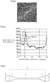
- Fig. 2 shows an example of a TEM image of the CNT assembled wire in accordance with the present embodiment.
- the image captured in the above step (a1) is binarized through the following procedure using the following image processing program.
- Image processing program Non-destructive paper surface fiber orientation analysis program "Fiber0ri8single03" (http://www.enomae.com/FiberOri/index.htm)
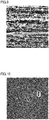
- Fig. 3 shows an image obtained by binarizing the TEM image of Fig. 2 .
- the image obtained in step (a2) is subjected to Fourier transform using the same image processing program (Non-destructive paper surface fiber orientation analysis program "FiberOri8single03" (http://www.enomae.com/FiberOri/index.htm)).
- Fig. 4 shows an image obtained from the Fig. 3 binarized image through Fourier-transform.
- Fig. 5 is a graph showing a relationship between degree of orientation and intensity of orientation obtained from the Fig. 4 Fourier transformed image.
- FWHM full width at half maximum
- degree of orientation 180 ° - full width at half maximum / 180 °
- a degree of orientation of 0 means being fully non-oriented.
- a degree of orientation of 1 means being fully oriented.
- the carbon nanotube assembled wire in accordance with the present embodiment preferably has a plurality of carbon nanotubes oriented at a degree of orientation of 0.9 or more and 1.0 or less. This means that the CNT assembled wire of the present embodiment has the plurality of CNTs highly oriented. Thus, the CNT assembled wire in accordance with the present embodiment can be elongated while maintaining the CNT's characteristics in electrical conductivity and mechanical strength.
- the CNT assembled wire When the CNT assembled wire has CNTs with a degree of orientation of less than 0.9, the CNT assembled wire tends to be reduced in electrical conductivity and mechanical strength.
- the lower limit value for the degree of orientation is preferably 0.93, more preferably 0.94, and still more preferably 0.95.
- the upper limit value for the degree of orientation is preferably 0.99, and more preferably 1.
- the carbon nanotube assembled wire has the shape of a yarn in which the plurality of carbon nanotubes are oriented and assembled together in their longitudinal direction.
- the length of the carbon nanotube assembled wire is not particularly limited, and can be adjusted as appropriate depending on the application.
- the length of the CNT assembled wire is preferably 100 ⁇ m or more, more preferably 1000 ⁇ m or more, and further preferably 10 cm or more, for example.
- the upper limit value for the length of the CNT assembled wire is not particularly limited, it is preferably 1 m or less from the viewpoint of manufacturing.
- the length of the CNT assembled wire can be measured through observation with a scanning electron microscope, an optical microscope, or visual observation.
- the size of the diameter of the carbon nanotube assembled wire is not particularly limited, and can be adjusted as appropriate depending on the application.
- the diameter of the CNT assembled wire is preferably 0.1 ⁇ m or more, and further preferably 1 ⁇ m or more, for example.
- the upper limit value for the diameter of the CNT assembled wire is not particularly limited, it is preferably 100 ⁇ m or less from the viewpoint of manufacturing.
- the size of the diameter of the CNT assembled wire is smaller than the length of the CNT assembled wire. That is, the direction of the length of the CNT assembled wire corresponds to the longitudinal direction.
- the diameter of the carbon nanotube assembled wire means an average outer diameter of a single CNT assembled wire.
- the average outer diameter of a single CNT assembled wire is obtained by observing cross sections at two arbitrary positions of the single CNT assembled wire with a transmission electron microscope or a scanning electron microscope, measuring, in each cross section, an outer diameter, which is the distance between farthest two points on the outer circumference of the CNT assembled wire, and calculating an average value of the obtained outer diameters.
- the carbon nanotube assembled wire includes at least one type of metal element selected from the group consisting of iron, nickel, cobalt, molybdenum, gold, silver, copper, yttrium, chromium, palladium, platinum and tungsten, and the metal element is dispersed in the carbon nanotube assembled wire in the longitudinal direction thereof.
- the metal element dispersed in the CNT assembled wire in the longitudinal direction thereof means that the metal element is not localized in the CNT assembled wire in the longitudinal direction thereof.
- the CNT assembled wire in accordance with the present embodiment includes these metal elements such that the metal elements are dispersed in the CNT assembled wire in the longitudinal direction thereof, so that the metal elements do not affect the CNT's characteristics in electric conductivity, and the CNT assembled wire can be elongated while maintaining the inherent electric conductivity.
- a total content of the metal elements in the CNT assembled wire is preferably 0.1% or more and 50% or less, more preferably 1% or more and 40% or less, and still more preferably 5% or more and 20% or less based on atomicity.
- the fact that the CNT assembled wire includes a metal element dispersed therein in the longitudinal direction thereof can be confirmed through EDX, electron energy loss spectrometry (EELS) or the like measurable at the same time as an electron microscope such as SEM and TEM.
- EDX electron energy loss spectrometry
- EELS electron energy loss spectrometry
- the carbon nanotube assembled wire includes the element of sulfur, and the element of sulfur is dispersed in the carbon nanotube assembled wire in the longitudinal direction thereof.
- the element of sulfur dispersed in the CNT assembled wire in the longitudinal direction thereof means that the element of sulfur is not localized in the CNT assembled wire in the longitudinal direction thereof.
- the element of sulfur originates from an assistive catalyst (CS 2 ) used in manufacturing the CNT assembled wire.
- the CNT assembled wire in accordance with the present embodiment includes the element of sulfur such that it is dispersed in the CNT assembled wire in the longitudinal direction thereof, so that the element of sulfur does not affect the CNT's characteristics in electric conductivity and mechanical strength, and the CNT assembled wire can be elongated while maintaining these characteristics.
- the CNT assembled wire includes the element of sulfur
- the content of the element of sulfur in the CNT assembled wire can be confirmed and measured through EDX, thermogravimetry, and X-ray photoelectron spectroscopy.
- the content of the element of sulfur in the CNT assembled wire is preferably 0.1% or more and 20% or less, more preferably 1% or more and 15% or less, and still more preferably 2% or more and 10% or less based on atomicity.
- the fact that the CNT assembled wire includes the element of sulfur dispersed therein in the longitudinal direction thereof can be confirmed by EDX, EELS or the like measurable at the same time as an electron microscope such as SEM and TEM.
- a carbon nanotube assembled wire manufacturing apparatus used for manufacturing a carbon nanotube assembled wire in accordance with Embodiment 6 will now be described with reference to Fig. 14 .
- Carbon nanotube assembled wire manufacturing apparatus 20 shown in Fig. 14 can include: a tubular carbon nanotube growing unit (hereinafter also referred to as a CNT growing unit) 21; a gas supplying unit 22 that supplies a carbon-containing gas into CNT growing unit 21 from one end of CNT growing unit 21 (in Fig. 14 , a right end thereof); a catalyst supplying unit 23 that supplies catalyst particles P into CNT growing unit 21; and a carbon nanotube assembling unit (hereinafter also referred to as a CNT assembling unit) that is disposed at the other end of CNT growing unit 21 (in Fig. 14 , a left end thereof) and orients and assembles a plurality of carbon nanotubes that are obtained in CNT growing unit 21 together in a direction along a flow of the carbon-containing gas.
- a tubular carbon nanotube growing unit hereinafter also referred to as a CNT growing unit
- a gas supplying unit 22 that supplies a carbon-containing gas into CNT growing unit 21 from one end
- Carbon nanotube growing unit 21 is in the form of a tube that is a quartz tube for example.
- carbon nanotubes 2 are formed on catalyst particles P by using a carbon-containing gas.
- Carbon nanotube growing unit 21 is disposed in electric furnace 28 and heated by a heater (not shown).
- the internal temperature in CNT growing unit 21 is preferably 800°C or more and 1200°C or less.
- the carbon-containing gas may be heated previously and then supplied from gas supplying unit 22 into CNT growing unit 21, or the carbon-containing gas may be heated in CNT growing unit 21.
- an area in cross section of a hollow portion passing the carbon-containing gas passes be smaller on the downstream side of the carbon-containing gas than on the upstream side of the carbon-containing gas. This allows the carbon-containing gas to have an average flow velocity larger on the downstream side than on the upstream side, and allows tensile force to be applied to carbon nanotube 2.
- a relationship that CNT growing unit 21 has between the area in cross section of the hollow portion on the downstream side of the carbon-containing gas and the area in cross section of the hollow portion on the upstream side of the carbon-containing gas can be the same as that described for the method for manufacturing a CNT assembled wire in accordance with Embodiment 4, and accordingly, will not be described repeatedly.
- Gas supplying unit 22 can be the same as the gas supplying unit described for the carbon nanotube manufacturing apparatus of Embodiment 3, and accordingly, will not be described repeatedly.
- Catalyst supplying unit 23 can be the same as the gas supplying unit described for the carbon nanotube manufacturing apparatus in accordance with Embodiment 3, and accordingly, will not be described repeatedly.
- Carbon nanotube assembling unit 24 is disposed at an end of CNT growing unit 21 opposite to gas supplying unit 23. That is, CNT assembling unit 24 is disposed downstream of CNT growing unit 21 as seen in the direction of the flow of the carbon-containing gas. In CNT assembling unit 24, a carbon nanotube assembled wire is formed.
- the CNT assembling unit may have any structure that can orient and assemble a plurality of suspended carbon nanotubes together in the direction of the flow of the carbon-containing gas.
- the CNT assembling unit can have a honeycomb structure, a straight-tube-type narrow tube structure, or the like.
- the honeycomb structure is disposed in the carbon nanotube assembled wire manufacturing apparatus such that the through holes have a longitudinal direction along the flow of the carbon-containing gas.
- the CNT assembling unit has a honeycomb structure, it can be identical in configuration to that described for the method for manufacturing a CNT assembled wire in accordance with Embodiment 4, and accordingly, it will not be described repeatedly.
- CNT assembled wire manufacturing apparatus 20a can include a magnetic field generating unit 24a that generates a magnetic field in addition to the above configuration.
- Magnetic field generating unit 24a is configured by disposing electric wire 301 in CNT growing unit 21 or CNT assembling unit 24 in the form of a coil surrounding reactor tube 31.
- electric wire 301 When a current is passed through electric wire 301, magnetic line of force 32 can be generated inside reactor tube 31 in a direction along the central axis of reactor tube 31 to generate a magnetic field.
- a tensile force derived from the magnetic field can thus be applied to CNTs.
- CNT assembled wire manufacturing apparatus 20b can include an electric field generating unit 24b that generates an electric field in addition to the above configuration.
- Electric field generating unit 24b is configured by disposing in CNT growing unit 21 or CNT assembling unit 24 positive electrode 33 made of a conductive material on a downstream side of the carbon-containing gas and negative electrode 34 made of a conductive material on an upstream side of the carbon-containing gas.
- an electric field can be generated by generating an electric field along the central axis of reactor tube 31. A tensile force derived from the electric field can thus be applied to CNTs.
- the carbon nanotube growing unit has a first flow channel therein
- the carbon nanotube assembling unit has one or more second flow channels therein, with each second flow channel having an area in cross section smaller than the first flow channel.
- the first flow channel corresponds to the hollow portion of CNT growing unit 21
- the second flow channel corresponds to the hollow portion of CNT assembling unit 24 (that is, a through hole of honeycomb structure 29).
- a tensile force toward the downstream side can be applied to the carbon nanotubes.
- the carbon nanotube assembling unit has a honeycomb structure having a plurality of second flow channels composed of a plurality of through holes, and each second flow channel has an area in cross section of 0.01 mm 2 or more and 4 mm 2 or less.
- each second flow channel has an area in cross section of 0.02 mm 2 or more and 2 mm 2 or less, and still more preferably 0.1 mm 2 or more and 1 mm 2 or less.
- a ratio S1/S2 is 100 or more and 1000000 or less, where S1 is an area in cross section of the first flow channel and S2 is an area in cross section of each of the second flow channels.
- S1/S2 is more preferably 1000 or more and 100000 or less, and still more preferably 2000 or more and 20000 or less.
- the plurality of carbon nanotubes are reduced in diameter.
- the CNT assembled wire including CNTs of a smaller diameter can be obtained.
- the second flow channels of the carbon nanotube assembling unit each have a length of 10 mm or more and 200 mm or less.
- the length of each second flow channel is more preferably 20 mm or more and 100 mm or less, and still more preferably 30 mm or more and 50 mm or less.
- the second flow channels each have a shape of a through hole with a helical groove in a periphery of the through hole.
- the gas in the second flow channel flows helically, so that a uniform twist angle is formed in the CNT assembled wire. Details of a case in which each second flow channel has a shape of a through hole with a helical groove in a periphery of the through hole have been described for the method for manufacturing a CNT assembled wire in accordance with Embodiment 4, and accordingly, will not be described repeatedly.
- each second flow channel has an area in cross section smaller on a downstream side than an upstream side.
- CNTs are assembled easily in the second flow channel, so that a CNT assembled wire is formed easily. Details of a case in which each second flow channel has an area in cross section smaller on the downstream side than the upstream side have been described for the method for manufacturing a CNT assembled wire in accordance with Embodiment 4, and accordingly, will not be described repeatedly.
- a method for manufacturing a carbon nanotube assembled wire bundle in accordance with Embodiment 7 can include: supplying a carbon-containing gas to a plurality of suspended catalyst particles to grow one or more carbon nanotubes from each of the plurality of catalyst particles (hereinafter also referred to as a growing step); applying a tensile force to a plurality of suspended carbon nanotubes to draw the plurality of carbon nanotubes (hereinafter also referred to as a drawing step); orienting and assembling the plurality of suspended carbon nanotubes together in a direction along the flow of the carbon-containing gas to obtain a plurality of carbon nanotube assembled wires (hereinafter also referred to as an assembling step); and orienting the plurality of carbon nanotube assembled wires in their longitudinal direction and thus bundling them together to obtain a carbon nanotube assembled wire bundle (hereinafter also referred to as a bundling step).
- the growing, drawing and assembling steps in the method for manufacturing a carbon nanotube assembled wire bundle are the same as those in the method for manufacturing a carbon nanotube assembled wire in accordance with Embodiment 4, and accordingly, will not be described repeatedly.
- a plurality of carbon nanotube assembled wires are oriented in their longitudinal direction and thus bundled together to obtain a carbon nanotube assembled wire bundle.
- the bundling step and the assembling step can be performed simultaneously. That is, in the assembling step, in parallel with production of CNT assembled wires, the obtained CNT assembled wires can be oriented in a direction along the longitudinal direction and thus bundled together to obtain a CNT assembled wire bundle. In this case, the bundling step is performed inside CNT assembling unit 24.
- the bundling step may be performed independently after the assembling step. That is, the bundling step can be performed after CNT assembled wires are produced in the assembling step.
- a CNT bundling unit is preferably connected downstream of CNT assembling unit 24 as seen in the direction of the flow of the carbon-containing gas.
- the CNT bundling unit can for example be a honeycomb structure, a straight-tube-type narrow tube structure, or the like.
- the bundling step includes: an adhering step of adhering a volatile liquid to the plurality of carbon nanotube assembled wires; and an evaporating step of evaporating the volatile liquid adhered to the carbon nanotube assembled wires.
- the obtained CNT assembled wire bundle has an enhanced density.
- Examples of the volatile liquid include methanol, ethanol, isopropyl alcohol, acetone, methyl ethyl ketone, xylene, anisole, toluene, cresol, pyrrolidone, carbitol, carbitol acetate, water, an epoxy monomer, and an acrylic monomer.
- the volatile liquid include monomer or resin.
- the adhering step is performed before orienting and bundling the plurality of carbon nanotube assembled wires in the direction along the longitudinal direction of the plurality of carbon nanotube assembled wires. This allows carbon nanotubes to be brought into close contact with each other uniformly and at a high density while the liquid with which the carbon nanotubes have gaps impregnated evaporates and thus escapes.
- the adhering step is performed after orienting and bundling the plurality of carbon nanotube assembled wires in the direction along the longitudinal direction of the plurality of carbon nanotube assembled wires. This allows carbon nanotubes to be brought into close contact with each other uniformly and at a high density while the liquid with which the carbon nanotubes have gaps impregnated evaporates and thus escapes.
- the evaporating step can be performed by natural drying.
- the bundling step is performed while tension is applied to the plurality of carbon nanotube assembled wires.
- the obtained CNT assembled wire bundle has an enhanced strength.
- the plurality of carbon nanotubes and the carbon-containing gas pass through a first flow channel
- the plurality of carbon nanotubes and the carbon-containing gas pass through one or more second flow channels located downstream of the first flow channel, with the one or more second flow channels each having an area in cross section smaller than an area in cross section of the first flow channel.
- the second flow channels each have a shape of a through hole with a helical groove in a periphery of the through hole.
- the gas in the second flow channel flows helically, so that a uniform twist angle is formed easily in the CNT assembled wire. Details of a case in which each second flow channel has a shape of a through hole with a helical groove in a periphery of the through hole have been described for the method for manufacturing a CNT assembled wire in accordance with Embodiment 4, and accordingly, will not be described repeatedly.
- each second flow channel has an area in cross section smaller on a downstream side than an upstream side.
- CNTs are assembled easily and CNT assembled wires are assembled easily, so that the CNT assembled wire and the CNT assembled wire bundle are formed easily. Details of a case in which each second flow channel has an area in cross section smaller on the downstream side than the upstream side have been described for the method for manufacturing a CNT assembled wire in accordance with Embodiment 4, and accordingly, will not be described repeatedly.
- Fig. 25 is a diagram showing an example of a honeycomb structure 29e including a plurality of second flow channels 240b.
- Fig. 26 is a view of honeycomb structure 29e of Fig. 25 as seen in a direction indicated by an arrow XXVI (or on an upstream side).
- Fig. 27 is a view of honeycomb structure 29e of Fig. 25 as seen in a direction indicated by an arrow XXVII (or on a downstream side).
- Fig. 28 is a cross section of the honeycomb structure of Fig. 25 taken along a line XXVIII-XXVIII.
- a distance between nearest neighbor second flow channels on the upstream side is indicated by a shortest distance dA between the peripheries of two second flow channels.
- a distance between nearest neighbor second flow channels on the downstream side is indicated by a shortest distance dB between the peripheries of two second flow channels.
- there are a plurality of second flow channels 240b and the distance between nearest neighbor second flow channels is shorter on the downstream side than on the upstream side (i.e., shortest distance dB is shorter than shortest distance dA).
- Fig. 29 is a diagram showing another example of a honeycomb structure 29f including a plurality of second flow channels 240c.
- Fig. 30 is a view of honeycomb structure 29f of Fig. 29 as seen in a direction indicated by an arrow XXX (or on the upstream side).
- Fig. 31 is a view of honeycomb structure 29f of Fig. 29 as seen in a direction indicated by an arrow XXXI (or on the downstream side).
- Fig. 32 is a cross section of the honeycomb structure of Fig. 29 taken along a line XXXII-XXXII.
- a distance between nearest neighbor second flow channels on the upstream side is indicated by a shortest distance dC between the peripheries of two second flow channels.
- the plurality of second flow channels 240c are connected at the downstream side (a left side in Fig. 32 ), and the shortest distance between the second flow channels on the downstream side is 0. That is, the embodiment shown in Figs. 29 to 32 corresponds to a case in which the distance between nearest neighbor second flow channels is shorter on the downstream side than on the upstream side (i.e., a shortest distance of 0 is shorter than shortest distance dC).
- the CNT assembled wires are bundled easily, so that the CNT assembled wire bundle is formed easily.
- the second flow channel may include two or more of the following forms (I) to (III) described above.
- the second flow channels each have a shape of a through hole with a helical groove in a periphery of the through hole.
- a distance between nearest neighbor second flow channels is shorter on a downstream side than on an upstream side.
- the second flow channels each have an area in cross section smaller on the downstream side than on the upstream side.
- FIG. 7 is a diagram for illustrating a carbon nanotube assembled wire bundle in accordance with an embodiment of the present disclosure.
- a carbon nanotube assembled wire bundle (hereinafter, also referred to as a CNT assembled wire bundle) 3 in accordance with the present embodiment preferably includes an oriented region in which carbon nanotube assembled wire 1 is oriented at a degree of orientation of 0.8 or more and 1 or less.
- carbon nanotube assembled wire 1 configuring carbon nanotube assembled wire bundle 3 the CNT assembled wire of Embodiment 5 can be used.
- carbon nanotube 2 configuring CNT assembled wire 1 the same carbon nanotube as described in Embodiment 2 can be used.
- carbon nanotube assembled wire 1 has carbon nanotube 2 oriented at a degree of orientation of 0.9 or more and 1 or less
- carbon nanotube assembled wire bundle 3 includes an oriented region in which carbon nanotube assembled wire 1 is oriented at a degree of orientation of 0.8 or more and 1 or less.
- the degree of orientation of the CNT in the carbon nanotube assembled wire has a value calculated in a method similar to the method described in Embodiment 5 for calculating a degree of orientation of a carbon nanotube in a carbon nanotube assembled wire, and accordingly, will not be described repeatedly.
- the degree of orientation of the CNT assembled wire in the carbon nanotube assembled wire bundle is basically a value calculated through a procedure similar to that of steps (a1) to (a6) described in Embodiment 5 for a method for calculating a degree of orientation. What is different is that, in step (a1), the CNT assembled wire bundle is imaged using the following equipment under the following conditions.
- Imaging conditions a magnification of 40 times to 100,000 times, and an acceleration voltage of 1 kV to 17 k. Measurement field of view: 30 ⁇ m ⁇ 30 ⁇ m
- Fig. 8 shows an SEM image of an example of the CNT assembled wire bundle in accordance with the present embodiment, as imaged under the above conditions.
- Fig. 9 shows an image obtained by binarizing the Fig. 8 SEM image in step (a2).
- Fig. 10 shows an image obtained by subjecting the Fig. 9 binarized image to Fourier transform in step (a3).
- Fig. 11 is a graph showing a relationship between degree of orientation and intensity of orientation obtained from the Fig. 10 Fourier transformed image in step (a4).
- step (a5) a full width at half maximum is measured based on the graph of Fig. 11 .
- step (a6) based on the full width at half maximum, degree of orientation is calculated by the following equation (1).
- degree of orientation 180 ° ⁇ full width at half maximum / 180 °
- a degree of orientation of 0 means being fully non-oriented.
- a degree of orientation of 1 means being fully oriented.
- the above measurement is performed at ten or more arbitrarily selected measurement fields of view.
- the carbon nanotube assembled wire bundle has the carbon nanotube assembled wires with a degree of orientation of 0.8 or more and 1 or less
- it is determined that the carbon nanotube assembled wire bundle includes an oriented region in which the carbon nanotube assembled wires are oriented at a degree of orientation of 0.8 or more and 1 or less.
- the carbon nanotube assembled wire bundle in accordance with the present embodiment is composed of carbon nanotube assembled wires composed of carbon nanotubes oriented at a degree of orientation of 0.9 or more and 1 or less, and the carbon nanotube assembled wire bundle includes an oriented region having carbon nanotube assembled wires oriented at a degree of orientation of 0.8 or more and 1 or less.
- the CNT assembled wire bundle of the present embodiment has the CNTs and CNT assembled wires highly oriented.
- the CNT assembled wire bundle in accordance with the present embodiment can be elongated while maintaining the CNT's characteristics in electrical conductivity and mechanical strength.
- the CNT assembled wire When the CNT assembled wire has CNTs with a degree of orientation of less than 0.9, the CNT assembled wire tends to be reduced in electrical conductivity and mechanical strength.
- the lower limit value for the degree of orientation is 0.9, preferably 0.93, more preferably 0.94, and still more preferably 0.95.
- the upper limit value for the degree of orientation is preferably 0.99, and more preferably 1.
- the CNT assembled wire bundle When the CNT assembled wire bundle has CNT assembled wires with a degree of orientation of less than 0.8, the CNT assembled wire bundle tends to be reduced in electrical conductivity and mechanical strength.
- the lower limit value for the degree of orientation is 0.8, preferably 0.83, and more preferably 0.85.
- the upper limit value for the degree of orientation is preferably 0.95, and more preferably 1.
- the carbon nanotube assembled wire bundle has the shape of a string in which a plurality of carbon nanotube assembled wires are oriented and assembled together in their longitudinal direction.
- the fact that the carbon nanotube assembled wire bundle has the shape of a string in which a plurality of carbon nanotube assembled wires are oriented and assembled together in their longitudinal direction can be confirmed by observation with an optical microscope or a scanning electron microscope.
- the length of the carbon nanotube assembled wire bundle is not particularly limited, and can be adjusted as appropriate depending on the application.
- the length of the CNT assembled wire bundle is preferably 100 ⁇ m or more, more preferably 1000 ⁇ m or more, and further preferably 10 cm or more, for example.
- the upper limit value for the length of the CNT assembled wire bundle is not particularly limited, it is preferably 1 m or less from the viewpoint of manufacturing.
- the length of the CNT assembled wire bundle can be measured through observation with an optical microscope or visual observation.
- the size of the diameter of the carbon nanotube assembled wire bundle is not particularly limited, and can be adjusted as appropriate depending on the application.
- the diameter of the CNT assembled wire bundle is preferably 1 ⁇ m or more, and further preferably 10 ⁇ m or more, for example.
- the upper limit value for the diameter of the CNT assembled wire bundle is not particularly limited, it is preferably 1000 ⁇ m or less from the viewpoint of manufacturing. In the present embodiment, the size of the diameter of the CNT assembled wire bundle is smaller than the length of the CNT assembled wire bundle.
- the diameter of the carbon nanotube assembled wire bundle means an average outer diameter of a single CNT assembled wire bundle.
- the average outer diameter of a single CNT assembled wire bundle is obtained by observing cross sections at two arbitrary positions of the single CNT assembled wire bundle with an optical microscope, measuring, in each cross section, an outer diameter, which is the distance between farthest two points on the outer circumference of the CNT assembled wire bundle, and calculating an average value of the obtained outer diameters.
- Fig. 12 is a SEM image of a carbon nanotube assembled wire bundle in accordance with one embodiment of the present disclosure.
- the carbon nanotube assembled wire bundle can include an oriented region 35 and an amorphous region 36 in which the carbon nanotube assembled wire has a degree of orientation of 0 or more and less than 0.8.
- the oriented region means a region in which the CNT assembled wire bundle has CNT assembled wires with a degree of orientation of 0.8 or more and 1.0 or less.
- the amorphous region means a region in which the CNT assembled wire bundle has CNT assembled wires with a degree of orientation of 0 or more and less than 0.8.
- a buffering function against bending or twisting can be added as desired while adjacent CNT assembled wires do not bond to each other.
- a proportion of the oriented region in the carbon nanotube assembled wire bundle is preferably 50% by volume or more and less than 100% by volume.
- the CNT assembled wire can have a sufficient degree of orientation.
- the proportion of the oriented region in the CNT assembled wire bundle is more preferably 60% by volume or more and 99% by volume or less, and still more preferably 70% by volume or more and 99% by volume or less.
- a proportion of the amorphous region in the carbon nanotube assembled wire bundle is preferably larger than 0% by volume and 50% by volume or less.
- the CNT assembled wire can have a sufficient degree of orientation.
- the proportion of the amorphous region in the CNT assembled wire bundle is more preferably 1% by volume or more and 40% by volume or less, and still more preferably 1% by volume or more and 30% by volume or less.
- a proportion of the oriented region and that of the amorphous region in the carbon nanotube assembled wire bundle is a value calculated through the following procedure of steps (b1) to (b3).
- a rectangular field of view of 1 mm ⁇ 1 mm for measurement is selected randomly at 10 locations or more.
- a degree of orientation of the CNT assembled wires in the CNT assembled wire bundle is calculated through a procedure similar to that followed in measuring a degree of orientation of CNT assembled wires in a CNT assembled wire bundle, as described above.
- a proportion of an oriented region in the CNT assembled wire bundle can be obtained by calculating a proportion of the number of measurement fields of view that show a degree of orientation of 0.8 or more and 1.0 or less (i.e., the oriented region) out of the ten or more measurement fields of view.
- a proportion of an amorphous region in the CNT assembled wire bundle can be obtained by calculating a proportion of the number of measurement fields of view that show a degree of orientation of 0 or more and less than 0.8 (i.e., the amorphous region) out of the ten or more measurement fields of view.
- a minimum value of a distance between adjacent ones of the plurality of carbon nanotube assembled wires is preferably 10 times or more an average diameter of the plurality of carbon nanotube assembled wires. According to this, a buffering function against bending or twisting can be added as desired while adjacent carbon nanotube assembled wires do not bond to each other.
- Fig. 13 is a diagram schematically showing an example of an oriented region of a CNT assembled wire bundle in accordance with an embodiment of the present disclosure.
- a distance between CNT assembled wires can be confirmed through the following procedure of steps (c1) and (c2).
- One oriented region is arbitrarily selected from oriented regions observed through steps (b1) to (b3), and a field of view of a square of 0.1 mm ⁇ 0.1 mm for measurement is set in the selected oriented region.
- a field of view of a square of 0.1 mm ⁇ 0.1 mm for measurement is set in the selected oriented region.
- at least one side of a square that is the peripheral frame of the measurement field of view is set to be substantially parallel to at least one of the carbon nanotube assembled wires.
- a carbon nanotube assembled wire 1a and one side W of the square are parallel to each other.
- being substantially parallel means that a specific carbon nanotube assembled wire and one side of a rectangle form an angle of 5° or less.
- a distance between adjacent carbon nanotube assembled wires is measured through observation with a scanning electron microscope.
- being between adjacent carbon nanotube assembled wires means being between a specific carbon nanotube assembled wire and a carbon nanotube assembled wire present closest to the specific carbon nanotube assembled wire.
- a CNT assembled wire adjacent to carbon nanotube assembled wire 1a shown in Fig. 13 is a carbon nanotube assembled wire 1b, and a minimum value of the distance between CNT assembled wire 1a and CNT assembled wire 1b is d1.
- a CNT assembled wire adjacent to a carbon nanotube assembled wire 1c is carbon nanotube assembled wire 1b, and a minimum value of the distance between CNT assembled wire 1c and CNT assembled wire 1b is d2.
- a CNT assembled wire adjacent to a carbon nanotube assembled wire Id is carbon nanotube assembled wire 1c, and a minimum value of the distance between CNT assembled wire Id and CNT assembled wire 1c is d3.
- Lengths d1, d2 and d3 are measured, and a minimum value of these is determined.
- the minimum value By comparing the minimum value with the average diameter of the plurality of carbon nanotube assembled wires, it can be confirmed whether the minimum value of the distances between adjacent ones of the plurality of carbon nanotube assembled wires is 10 times or more the average diameter of the plurality of carbon nanotube assembled wires in at least a portion of the oriented region of the CNT assembled wire bundle.
- the average diameter of the plurality of carbon nanotube assembled wires means an average diameter of the plurality of carbon nanotube assembled wires present in the measurement field of view set in step (c1).
- the diameter of the carbon nanotube assembled wire means an average outer diameter of a single CNT assembled wire.
- the average outer diameter of each of CNT assembled wires 1a, 1b, 1c, 1d is obtained by directly observing cross sections at two arbitrary positions of each CNT assembled wire with a transmission electron microscope or a scanning electron microscope, measuring, in each cross section, an outer diameter, which is the distance between farthest two points on the outer circumference of the CNT assembled wire, and calculating an average value of the obtained outer diameters.
- the average diameter of the plurality of carbon nanotube assembled wires in the measurement field or view is calculated from the average outer diameter of each of CNT assembled wires 1a, 1b, 1c, and Id.
- the minimum value of the distances between adjacent ones of the plurality of carbon nanotube assembled wires is preferably 10 times or more and 50 times or less, more preferably 15 times or more and 40 times or less, and still more preferably 20 times or more and 30 times or less of the average diameter of the plurality of carbon nanotube assembled wires.
- the minimum value of the distances between adjacent ones of the plurality of carbon nanotube assembled wires exceeds 50 times the average diameter of the plurality of carbon nanotube assembled wires, many gaps result and accordingly, foreign matters are easily introduced, and when an external force is applied, stress concentration occurs in the vicinity of the foreign matters and the buffering function is reduced, and the carbon nanotube assembled wires may break.
- a maximum value of angles between adjacent carbon nanotube assembled wires is preferably 10° or less. According to this, a buffering function against bending or twisting can be added as desired while adjacent carbon nanotube assembled wires do not bond to each other.
- an angle between adjacent carbon nanotubes in at least a portion of an oriented region of a CNT assembled wire can be confirmed through the following procedure of steps (d1) and (d2).
- an angle between adjacent carbon nanotube assembled wires in at least a portion of an oriented region of a CNT assembled wire bundle can be confirmed through the following procedure of steps (d1) and (d2).
- a measurement field of view of a square of 0.1 mm ⁇ 0.1 mm is determined in a manner similar to that in step (c1).
- an angle between adjacent carbon nanotube assembled wires is measured.
- being between adjacent carbon nanotube assembled wires means being between a specific carbon nanotube assembled wire and a carbon nanotube assembled wire present closest to the specific carbon nanotube assembled wire.
- a CNT assembled wire adjacent to carbon nanotube assembled wire 1a shown in Fig. 13 is carbon nanotube assembled wire 1b, and an angle between CNT assembled wire 1a and CNT assembled wire 1b, which is equal to an angle between a line 1a' parallel to CNT assembled wire 1a and CNT assembled wire 1b, is ⁇ 1°.
- a CNT assembled wire adjacent to carbon nanotube assembled wire 1c is carbon nanotube assembled wire 1b, and an angle between CNT assembled wire 1c and CNT assembled wire 1b, which is equal to an angle between a line 1c' parallel to CNT assembled wire 1c and CNT assembled wire 1b, is ⁇ 2°.
- a CNT assembled wire adjacent to carbon nanotube assembled wire 1c is carbon nanotube assembled wire Id, and CNT assembled wire 1c and CNT assembled wire Id are parallel to each other and form an angle of 0°.
- angles ⁇ 1° and ⁇ 2° have a maximum value of 10° or less, it is determined that an angle between adjacent carbon nanotube assembled wires is 10° or less in at least a portion of the oriented region of the CNT assembled wire bundle.
- the angle between adjacent carbon nanotube assembled wires is preferably 10° or less, more preferably 9° or less, still more preferably 5° or less, and most preferably 0°.
- the carbon nanotube assembled wire bundle includes at least one type of metal element selected from the group consisting of iron, nickel, cobalt, molybdenum, gold, silver, copper, yttrium, chromium, palladium, platinum and tungsten, and the metal element is dispersed in the carbon nanotube assembled wire bundle in the longitudinal direction thereof.
- the metal element dispersed in the CNT assembled wire bundle in the longitudinal direction thereof means that the metal element is not localized in the CNT assembled wire in the longitudinal direction thereof.
- the CNT assembled wire bundle in accordance with the present embodiment includes these metal elements such that the metal elements are dispersed in the CNT assembled wire bundle in the longitudinal direction thereof, so that the metal elements do not affect the CNT's characteristics in electric conductivity, and the CNT assembled wire bundle can be elongated while maintaining the inherent electric conductivity.
- a total content of the metal element in the CNT assembled wire bundle is preferably 0.1% or more and 50% or less, more preferably 1% or more and 40% or less, and still more preferably 5% or more and 20% or less based on atomicity.
- the fact that the CNT assembled wire bundle includes a metal element dispersed therein in the longitudinal direction thereof can be confirmed through EDX, electron energy loss spectrometry (EELS) or the like measurable at the same time as an electron microscope such as SEM and TEM.
- EDX electron energy loss spectrometry
- EELS electron energy loss spectrometry
- the carbon nanotube assembled wire bundle includes the element of sulfur, and the element of sulfur is dispersed in the carbon nanotube assembled wire bundle in the longitudinal direction thereof.
- the element of sulfur dispersed in the CNT assembled wire bundle in the longitudinal direction thereof means that the element of sulfur is not localized in the CNT assembled wire bundle in the longitudinal direction thereof.
- the element of sulfur originates from an assistive catalyst (CS 2 ) used in manufacturing the CNT assembled wire bundle.
- the CNT assembled wire bundle in accordance with the present embodiment includes the element of sulfur such that it is dispersed in the CNT assembled wire bundle in the longitudinal direction thereof, so that the element of sulfur does not affect the CNT's characteristics in electric conductivity and mechanical strength, and the CNT assembled wire bundle can be elongated while maintaining these characteristics.
- the CNT assembled wire bundle includes the element of sulfur
- the content of the element of sulfur in the CNT assembled wire bundle can be confirmed and measured through EDX, thermogravimetry, and X-ray photoelectron spectroscopy.
- the content of the element of sulfur in the CNT assembled wire bundle is preferably 0.1% or more and 20% or less, more preferably 1% or more and 15% or less, and still more preferably 2% or more and 10% or less based on atomicity.
- the fact that the CNT assembled wire bundle includes the element of sulfur dispersed therein in the longitudinal direction thereof can be confirmed by EDX, EELS or the like measurable at the same time as an electron microscope such as SEM and TEM.
- FIGS. 21 and 22 are diagrams showing a carbon nanotube assembled wire bundle manufacturing apparatus.
- Carbon nanotube assembled wire bundle manufacturing apparatuses 500, 501 can include: carbon nanotube assembled wire manufacturing apparatus 20 described in Embodiment 6; and a bundling unit 50 that obtains a carbon nanotube assembled wire bundle by orienting and bundling a plurality of carbon nanotube assembled wires, which are obtained by the carbon nanotube assembled wire manufacturing apparatus, in a direction along a longitudinal direction of the plurality of carbon nanotube assembled wires.
- Carbon nanotube assembled wire manufacturing apparatus 20 can have the same structure as that of the carbon nanotube assembled wire manufacturing apparatus described for Embodiment 6, and accordingly, it will not be described repeatedly.
- bundling unit 50 a plurality of suspended CNT assembled wires are oriented in their longitudinal direction and thus bundled together to form a carbon nanotube assembled wire bundle.
- the bundling unit may have any structure that can orient a plurality of carbon nanotube assembled wires that are obtained in a carbon nanotube assembled wire manufacturing apparatus, and assemble them together in their longitudinal direction.
- the bundling unit can have a honeycomb structure, a straight-tube-type narrow tube structure, or the like.
- the honeycomb structure is disposed in the carbon nanotube assembled wire bundle manufacturing apparatus such that the through holes have a longitudinal direction along the flow of the carbon-containing gas.
- the bundling unit When the bundling unit has a honeycomb structure, it can be identical in configuration to that described for the above-described CNT assembled wire manufacturing apparatus.
- the bundling unit can have a structure shared by the carbon nanotube assembling unit. That is, the CNT assembling unit can also function as the bundling unit.
- the bundling unit can have a structure separate from the carbon nanotube assembling unit.
- the bundling unit is preferably disposed downstream of CNT assembling unit 24 as seen in the direction of the flow of the carbon-containing gas.
- a diaphragm 55 is provided to the bundling unit disposed downstream of a CNT assembled wire, and a plurality of carbon nanotube assembled wires 1 are passed through diaphragm 55 and thus oriented and assembled together in their longitudinal direction.
- bundling unit 50 includes a liquid adhering apparatus 51 that adheres a volatile liquid 53 to the plurality of carbon nanotube assembled wires 1.
- a CNT assembled wire bundle having a high density can be provided.
- Liquid adhering apparatus 51 is disposed at a position where carbon nanotube assembled wire 1 can be exposed to the volatile liquid.
- liquid adhering apparatus 51 can be disposed downstream of diaphragm 55.
- liquid adhering apparatus 51 can be disposed upstream of diaphragm 55.
- the bundling unit includes a winding apparatus 52 that orients, bundles and winds the plurality of carbon nanotube assembled wires in a direction along the longitudinal direction of the plurality of carbon nanotube assembled wires while applying tension to the plurality of carbon nanotube assembled wires.
- a winding apparatus 52 that orients, bundles and winds the plurality of carbon nanotube assembled wires in a direction along the longitudinal direction of the plurality of carbon nanotube assembled wires while applying tension to the plurality of carbon nanotube assembled wires.
- the CNT assembled wire bundle manufacturing apparatus can include in addition to the above configuration a magnetic field generating unit that generates a magnetic field. It can be configured to be identical to the magnetic field generating unit described for the above CNT assembled wire manufacturing apparatus.
- the CNT assembled wire bundle manufacturing apparatus can include, in addition to the above configuration, an electric field generating unit that generates an electric field. It can be configured to be identical to the electric field generating unit described for the above CNT assembled wire manufacturing apparatus.
- the carbon nanotube assembling unit and the bundling unit are formed of the same honeycomb structural body having a plurality of second flow channels, and the second flow channels each have a shape of a through hole with a helical groove in a periphery of the through hole.
- the gas in the second flow channel flows helically, so that a uniform twist angle is formed easily in the CNT assembled wire. Details of a case in which each second flow channel helically extends have been described for the method for manufacturing a CNT assembled wire in accordance with Embodiment 4, and accordingly, will not be described repeatedly.
- a distance between nearest neighbor second flow channels of the plurality of second flow channels is shorter in a downstream side of the nearest neighbor second flow channels than in an upstream side of the nearest neighbor second flow channels.
- the CNT assembled wires are bundled easily, so that the CNT assembled wire bundle is formed easily. Details of a case in which a distance between nearest neighbor second flow channels of the plurality of second flow channels is shorter in a downstream side of the nearest neighbor second flow channels than in an upstream side of the nearest neighbor second flow channels have been described for the method for manufacturing a CNT assembled wire bundle in accordance with Embodiment 7, and accordingly, will not be described repeatedly.
- each second flow channel has an area in cross section smaller on the downstream side than the upstream side.
- CNTs are assembled easily and CNT assembled wires are assembled easily, so that the CNT assembled wire and the CNT assembled wire bundle are formed easily. Details of a case in which each second flow channel has an area in cross section smaller on the downstream side than the upstream side have been described for the method for manufacturing a CNT assembled wire in accordance with Embodiment 4, and accordingly, will not be described repeatedly.
- a carbon nanotube manufacturing apparatus having a configuration similar to that of a carbon nanotube manufacturing apparatus outlined as shown in Fig. 18 was prepared. Specifically, carbon nanotube growing unit 21 and carbon nanotube drawing unit 30 are disposed in electric furnace 28.
- the CNT growing unit is a quartz tube having an inner diameter of 20 mm and a length of 800 mm.
- Carbon nanotube drawing unit 30 is a quartz tube in communication with the carbon nanotube growing unit, and has an average inner diameter of 8 mm and a length of 300 mm.
- Catalyst supplying unit 23 is disposed on a side of CNT growing unit 21 opposite to a side thereof in communication with CNT drawing unit 30.
- Catalyst supplying unit 23 is a quartz tube having an inner diameter of 20 mm and a length of 200 mm, and is disposed in communication with the CNT growing unit.
- ferrocene is disposed as a catalyst on catalyst holder 26.
- Catalyst supplying unit 23 is heated by heater 25.
- Gas supplying unit 22 is disposed on a side of catalyst supplying unit 23 opposite to a side thereof connected to CNT growing unit 21.
- Apparatus 1 corresponds to an example.
- Apparatus 2 differs from apparatus 1 in that the former does not include carbon nanotube drawing unit 30. That is, in this apparatus, the CNT drawing unit is not disposed at an end of CNT growing unit 21 that is located on a side opposite to a side in communication with catalyst supplying unit 23. Note that the length of the carbon nanotube growing unit of apparatus 2 was the same as the total length of the carbon nanotube growing unit and the carbon nanotube drawing unit of apparatus 1.
- Apparatus 2 corresponds to a comparative example.
- Carbon nanotubes for samples 1 and 2 were prepared using apparatuses 1 and 2, respectively, as manufacturing apparatuses. Initially, in each of apparatuses 1 and 2, an electric furnace's internal temperature was raised to 1000°C while argon gas having an argon gas concentration of 100% by volume was supplied from the gas supplying unit into the CNT growing unit at a flow rate of 1000 cc/min (flow velocity: 3.4 cm/sec) for 50 minutes. Subsequently, in addition to the argon gas, methane gas was supplied at a flow rate of 50 cc/min (flow velocity: 0.17 cm/sec) and carbon disulfide (CS 2 ) gas was supplied at a flow rate of 1 cc/min (flow velocity: 0.003 cm/sec) for 120 minutes. A gaseous mixture including the argon gas, the methane gas, and the carbon disulfide (i.e., the carbon-containing gas) as a whole has a flow velocity of 3.6 cm/sec.
- the carbon nanotubes of samples 1 and 2 were measured in average length and average diameter. How the average length and the average diameter were measured is the same as has been described in Embodiment 2, and accordingly, it will not be described repeatedly.
- the CNT of sample 1 was a carbon nanotube drawn in its longitudinal direction in the form of a linear yarn, and had an average length of 10 ⁇ m and an average diameter of 1.2 nm.
- the CNT of sample 2 had an average length of 2 ⁇ m and an average diameter of 1.2 nm. From the above, it has been confirmed that the CNT (sample 1) obtained by apparatus 1 is longer than the CNT (sample 2) obtained by apparatus 2.
- a carbon nanotube assembled wire manufacturing apparatus having a configuration similar to that of the carbon nanotube assembled wire manufacturing apparatus outlined in Fig. 14 was prepared.
- carbon nanotube growing unit 21 and carbon nanotube assembling unit 24 are disposed in electric furnace 28.
- the CNT growing unit is a quartz tube having an inner diameter of 20 mm and a length of 800 mm.
- a ceramic honeycomb structure is disposed in a quartz tube in communication with the CNT growing unit.
- the honeycomb structure has about 200 through holes per inch, and each throughhole has an area in cross section of 0.8 mm 2 .
- Catalyst supplying unit 23 is disposed on a side of CNT growing unit 21 opposite to a side thereof in communication with CNT assembling unit 24.
- Catalyst supplying unit 23 is a quartz tube having an inner diameter of 20 mm and a length of 200 mm, and is disposed in communication with the CNT growing unit.
- ferrocene is disposed as a catalyst on catalyst holder 26.
- Catalyst supplying unit 23 is heated by heater 25.
- Gas supplying unit 22 is disposed on a side of catalyst supplying unit 23 opposite to a side thereof connected to CNT growing unit 21.
- Apparatus 3 corresponds to an example.
- Apparatus 4 differs from apparatus 3 in that the former does not include carbon nanotube assembling unit 24. That is, in this apparatus, the CNT assembling unit is not disposed at an end of CNT growing unit 21 that is located on a side opposite to a side in communication with catalyst supplying unit 23. Apparatus 4 corresponds to a comparative example.
- Apparatus 5 differs from apparatus 3 in that the honeycomb structure is not disposed downstream of the carbon nanotube growing unit, as shown in Fig. 19 by a honeycomb structure 29a; rather, it is disposed inside carbon nanotube growing unit 21 at an upstream side as seen in the direction of the flow of the carbon-containing gas, as shown by a honeycomb structure 29b. Apparatus 5 corresponds to a comparative example.
- Apparatus 6 As an apparatus 6, an apparatus having a configuration basically similar to that of apparatus 3 was prepared. Apparatus 6 differs from apparatus 3 in that the honeycomb structure is not disposed downstream of the carbon nanotube growing unit, as shown in Fig. 19 by honeycomb structure 29a; rather, it is disposed inside catalyst supplying unit 23, as shown by a honeycomb structure 29c. Apparatus 6 corresponds to a comparative example.
- Carbon nanotube assembled wires for samples 3 to 6 were produced using apparatuses 3 to 6, respectively, as manufacturing apparatuses. Initially, in each of apparatuses 3 to 6, an electric furnace's internal temperature was raised to 1000°C while an argon gas having an argon gas concentration of 100% by volume was supplied from the gas supplying unit into the CNT growing unit at a flow rate of 1000 cc/min (flow velocity: 3.4 cm/sec) for 50 minutes.
- methane gas was supplied at a flow rate of 50 cc/min (flow velocity: 0.17 cm/sec) and carbon disulfide (CS 2 ) gas was supplied at a flow rate of 1 cc/min (flow velocity: 0.003 cm/sec) for 120 minutes.
- a gaseous mixture including the argon gas, the methane gas, and the carbon disulfide (i.e., the carbon-containing gas) as a whole has a flow velocity of 3.6 cm/sec.
- the carbon nanotube assembled wires of samples 3 and 4 had their degrees of orientation measured.
- the method used herein for calculating the degrees of orientation is the same as the method described in Embodiment 5, and accordingly, it will not be described repeatedly.
- FIG. 2 A TEM image of the CNT assembled wire of sample 3 is shown in Fig. 2 , and a Fourier transformed image thereof is shown in Fig. 4.
- Fig. 5 shows a relationship between angle of orientation and intensity of orientation presented by sample 1.
- Sample 3 provided a full width at half maximum of 12° and a degree of orientation of 0.93.
- Sample 4 provided a full width at half maximum of 54° and a degree of orientation of 0.70.
- the carbon nanotube assembled wire of sample 3 had its average length and average diameter measured. How the average length and the average diameter were measured is the same as has been described in Embodiment 5, and accordingly, it will not be described repeatedly.
- the CNT assembled wire of sample 3 was in the form of a linear yarn composed of a plurality of carbon nanotubes oriented and assembled together in their longitudinal direction, and had an average length of 10 cm and an average diameter of 50 ⁇ m.
- the carbon nanotube assembled wire of sample 3 was subjected to EDX analysis to identify an element included in the CNT assembled wire that originates from the catalyst.
- Sample 3 was confirmed to include iron and sulfur. In addition, through SEM observation and EDX analysis, it has been confirmed that iron and sulfur are dispersed longitudinally of the CNT assembled wire.
- Apparatus 7 a carbon nanotube assembled wire bundle manufacturing apparatus having a configuration basically similar to that of apparatus 3 was prepared. Apparatus 7 differs from apparatus 3 in that the former introduces an orifice plate on the outlet side of the honeycomb in order to converge CNT assembled wires to one point.
- an apparatus having a configuration basically similar to that of apparatus 7 was prepared.
- the apparatus differs from apparatus 7 in that the former does not include a mechanism for converging CNT assembled wires.
- Carbon nanotube assembled wire bundles for samples 7 and 8 were produced using manufacturing apparatuses that are apparatuses 7 and 8, respectively. Initially, in each of apparatuses 7 and 8, an electric furnace's internal temperature was raised to 1000°C while an argon gas having an argon gas concentration of 100% by volume was supplied from the gas supplying unit into the CNT growing unit at a flow rate of 1000 cc/min (flow velocity: 3.4 cm/sec) for 50 minutes.
- methane gas was supplied at a flow rate of 50 cc/min (flow velocity: 0.17 cm/sec) and carbon disulfide (CS 2 ) gas was supplied at a flow rate of 1 cc/min (flow velocity: 0.003 cm/sec) for 120 minutes.
- a gaseous mixture including the argon gas, the methane gas, and the carbon disulfide (i.e., the carbon-containing gas) as a whole has a flow velocity of 3.6 cm/sec.
- the carbon nanotube assembled wire bundles of samples 7 and 8 had their degrees of orientation measured.
- the method used herein to calculate a degree of orientation of CNT in a CNT assembled wire is the same as the method described in Embodiment 5, and accordingly, it will not be described repeatedly.
- the method used herein to calculate a degree of orientation of a CNT assembled wire in a CNT assembled wire bundle is the same as that described in Embodiment 8, and accordingly, it will not be described repeatedly.
- the CNT assembled wire bundle of sample 7 was composed of CNT assembled wires composed of CNTs having a degree of orientation of 0.94, and the CNT assembled wire bundle was composed of CNT assembled wires having a degree of orientation of 0.93.
- the CNT assembled wire bundle of sample 8 was composed of CNT assembled wires composed of CNTs having a degree of orientation of 0.93, and the CNT assembled wire bundle was composed of CNT assembled wires having a degree of orientation of 0.76.
- the CNT assembled wire bundle obtained from apparatus 7 is composed of CNT assembled wires composed of CNTs having a higher degree of orientation and is also composed of CNT assembled wires having a higher degree of orientation than the CNT assembled wire bundle obtained from apparatus 8 (sample 8).
- the carbon nanotube assembled wire bundle of sample 7 had its average length and average diameter measured. How the average length and the average diameter were measured is the same as has been described in Embodiment 8, and accordingly, it will not be described repeatedly.
- the CNT assembled wire bundle of sample 7 was in the form of a linear yarn composed of a plurality of carbon nanotube assembled wires oriented and assembled together in their longitudinal direction, and had an average length of 10 cm and an average diameter of 200 ⁇ m.
- CNT assembled wires included in the carbon nanotube assembled wire bundle of sample 7 were subjected to EDX analysis to identify an element included in the CNT assembled wire that originates from the catalyst.
- Sample 7 was confirmed to include iron and sulfur. In addition, through SEM observation and EDX analysis, it has been confirmed that iron and sulfur are dispersed longitudinally of the CNT assembled wire.
- the carbon nanotube assembled wire bundle of sample 7 was subjected to measurement of a proportion in volume of the oriented region and the amorphous region. How the proportion in volume of the oriented region and the amorphous region was measured is the same as described in Embodiment 8, and accordingly, it will not be described repeatedly.
- the CNT assembled wire bundle of sample 7 had 80% by volume of oriented region and 20% by volume of amorphous region.
- the carbon nanotube assembled wire bundle of sample 7 was subjected to measurement of a minimum value of a distance between adjacent ones of a plurality of carbon nanotube assembled wires in the oriented region. It was also subjected to measurement of an average diameter of the CNT assembled wires constituting the CNT assembled wire bundle. How a minimum value of a distance between adjacent ones of the plurality of carbon nanotube assembled wires in the oriented region and an average diameter of the CNT assembled wires were measured is the same as has been described in Embodiment 8, and accordingly, it will not be described repeatedly.
- the minimum value of the distance between adjacent ones of the plurality of carbon nanotube assembled wires in the oriented region was 300 nm, and the average diameter of the CNT assembled wires was 25 nm. That is, it has been confirmed that the minimum value of the distance between adjacent ones of the plurality of carbon nanotube assembled wires was 10 times or more the average diameter of the plurality of carbon nanotube assembled wires.
- the carbon nanotube assembled wire bundle of sample 7 was subjected to measurement of a maximum value of an angle between adjacent carbon nanotube assembled wires in the oriented region. How an angle between adjacent carbon nanotube assembled wires in the oriented region was measured is the same as has been described in Embodiment 8, and accordingly, it will not be described repeatedly.
- the oriented region had adjacent carbon nanotube assembled wires forming an angle having a maximum value of 9°. That is, it has been confirmed that the maximum value of the angle between adjacent carbon nanotube assembled wires was 10° or less.
- CNT assembled wire manufacturing apparatuses were used to investigate a relationship between an area in cross section of the second flow channel of the CNT assembling unit and a diameter and length of a CNT included in an obtained CNT assembled wire.
- Apparatuses 9 to 14 are similar in configuration to the carbon nanotube assembled wire manufacturing apparatus shown in Fig. 14 .
- carbon nanotube growing unit 21 and carbon nanotube assembling unit 24 are disposed in electric furnace 28.
- the CNT growing unit is a quartz tube having an inner diameter of 20 mm and a length of 800 mm.
- a ceramic honeycomb structure is disposed in a quartz tube in communication with the CNT growing unit.
- Apparatuses 9 to 14 each have a honeycomb structure with each throughhole (i.e., the second flow channel) having an area in cross section and a length as shown in Table 1.
- apparatus 9 has a honeycomb structure with each throughhole (i.e., the second flow channel) having an area in cross section of 1 mm 2 and a length of 50 mm.
- Catalyst supplying unit 23 is disposed on a side of CNT growing unit 21 opposite to a side thereof in communication with CNT assembling unit 24.
- Catalyst supplying unit 23 is a quartz tube having an inner diameter of 20 mm and a length of 200 mm, and is disposed in communication with the CNT growing unit.
- ferrocene is disposed as a catalyst on catalyst holder 26.
- Catalyst supplying unit 23 is heated by heater 25.
- Gas supplying unit 22 is disposed on a side of catalyst supplying unit 23 opposite to a side thereof connected to CNT growing unit 21. Apparatuses 9-14 correspond to examples.
- Carbon nanotube assembled wires were produced using apparatuses 9-14 as manufacturing apparatuses. Initially, in each of apparatuses 9 to 14, an electric furnace's internal temperature was raised to 1000°C while an argon gas having an argon gas concentration of 100% by volume was supplied from the gas supplying unit into the CNT growing unit at a flow rate of 1000 cc/min (flow velocity: 3.4 cm/sec) for 50 minutes. Subsequently, in addition to the argon gas, methane gas was supplied at a flow rate of 50 cc/min (flow velocity: 0.17 cm/sec) and carbon disulfide (CS 2 ) gas was supplied at a flow rate of 1 cc/min (flow velocity: 0.003 cm/sec) for 120 minutes. A gaseous mixture including the argon gas, the methane gas, and the carbon disulfide (i.e., the carbon-containing gas) as a whole has a flow velocity of 3.6 cm/sec.
- the carbon-containing gas had a temperature of 1000°C on the upstream side of the CNT assembling unit and a temperature of 600°C on the downstream side of the CNT assembling unit.
- the CNT assembled wires of samples 9 to 14 had their degrees of orientation and their CNTs' diameters. How their degrees of orientation and their CNTs' diameters were measured is the same as has been described in Embodiment 5, and accordingly, it will not be described repeatedly. A result thereof is indicated in table 1, the "CNT” column, the "degree of orientation” and “diameter” subcolumns. Table 1 samples 2nd flow channel (through hole) CNT area in cross section (mm 2 ) length (mm) degree of orientation diameter (nm) 9 9.61 50 0.90 2 10 4 50 0.92 1.5 11 1.96 50 0.92 1.5 12 1.96 100 0.94 1 13 1.21 50 0.94 1 14 0.81 50 0.94 1
- an electric furnace's internal temperature was raised to 1200°C while an argon gas having an argon gas concentration of 100% by volume was supplied from the gas supplying unit into the CNT growing unit at a flow rate of 1000 cc/min (flow velocity: 3.4 cm/sec) for 50 minutes.
- methane gas was supplied at a flow rate of 50 cc/min (flow velocity: 0.17 cm/sec) and carbon disulfide (CS 2 ) gas was supplied at a flow rate of 1 cc/min (flow velocity: 0.003 cm/sec) for 120 minutes.
- a gaseous mixture including the argon gas, the methane gas, and the carbon disulfide (i.e., the carbon-containing gas) as a whole has a flow velocity of 3.6 cm/sec.
- the carbon-containing gas has a temperature of 1200°C on the upstream side of the CNT assembling unit and a temperature of 600°C on the downstream side of the CNT assembling unit, and a temperature of 600°C at a downstream end inside of the throughhole (or second flow channel) of the CNT assembling unit.
- a CNT assembled wire was produced in a method similar to that of manufacturing process 9-1, except that the carbon-containing gas had a temperature of 500°C on the downstream side of the CNT assembling unit.
- a CNT assembled wire was produced in a manner similar to manufacturing process 9-1, except that the carbon-containing gas had a temperature of 300°C on the downstream side of the CNT assembling unit and at the downstream end inside of the throughhole (or second flow channel) of the CNT assembling unit.
- manufacturing process 9-2 when the downstream side of the CNT assembling unit was observed with a TEM, it has been confirmed that single CNTs were also present together with a CNT assembled wire.
- the manufacturing process presented a lower ratio of single CNTs than manufacturing process 9-1.
- an apparatus including a CNT assembled wire manufacturing apparatus having the same configuration as that of apparatus 9 of study 4 and a bundling unit including a diaphragm and a winding apparatus downstream of the CNT assembled wire manufacturing apparatus was prepared.
- apparatus 10-2 a CNT assembled wire bundle manufacturing apparatus having the configuration shown in Fig. 21 was prepared.
- apparatus 10-2 is similar in configuration to apparatus 10-1, and furthermore, downstream of the diaphragm, includes a liquid adhering apparatus followed by a winding apparatus. Ethanol is sealed in the liquid adhering apparatus.
- apparatus 10-3 a CNT assembled wire bundle manufacturing apparatus having a configuration shown in Fig. 22 was prepared.
- apparatus 10-3 is similar in configuration to apparatus 10-1, and further includes a liquid adhering apparatus disposed between a CNT assembled wire manufacturing apparatus and a diaphragm, and a winding apparatus disposed downstream of the diaphragm. Ethanol is sealed in the liquid adhering apparatus as a volatile liquid.
- CNT assembled wires were manufactured under conditions similar to those in manufacturing process 9-1, and subsequently, the CNT assembled wires were bundled through a diaphragm to obtain a CNT assembled wire bundle for sample 10-1.
- the bundling step was performed while applying tension to the CNT assembled wires by winding the CNT assembled wire bundle with the winding apparatus.
- CNT assembled wires were manufactured under conditions similar to those in manufacturing process 9-1 and bundled together through a diaphragm, and subsequently, a volatile liquid in the form of vapor was adhered to the CNT assembled wires and thereafter the volatile liquid was naturally dried and thus evaporated to obtain a CNT assembled wire bundle for sample 10-2.
- the bundling step was performed while applying tension to the CNT assembled wires by winding the CNT assembled wire bundle with the winding apparatus.
- CNT assembled wires were manufactured under conditions similar to those in manufacturing process 9-1 and a volatile liquid in the form of vapor was adhered to the CNT assembled wires, and subsequently, the CNT assembled wires were bundled together through a diaphragm and the volatile liquid was naturally dried and thus evaporated to obtain a CNT assembled wire bundle for sample 10-3.
- the bundling step was performed while applying tension to the CNT assembled wires by winding the CNT assembled wire bundle with the winding apparatus.
- the carbon nanotube assembled wire bundles of samples 10-1 to 10-4 had their degrees of orientation measured.
- the method used herein to calculate a degree of orientation of CNT (hereinafter also referred to as "CNT's degree of orientation") in a CNT assembled wire is the same as the method described in Embodiment 5, and accordingly, it will not be described repeatedly.
- the method used herein to calculate a degree of orientation of CNT assembled wires (hereinafter also referred to as "CNT assembled wire's degree of orientation”) in a CNT assembled wire bundle is the same as the method described in Embodiment 8, and accordingly, it will not be described repeatedly.
- a result thereof is shown in table 2, the "CNT's degree of orientation” and "CNT assembled wire's degree of orientation” columns.
- the carbon nanotube assembled wire bundles of samples 10-1 to 10-4 were measured in density. Density was calculated based on the CNT assembled wire bundle's volume and weight, and represented in % as compared with 100% of CNT. A result thereof is shown in table 2, the "density" column.
- the carbon nanotube assembled wire bundles of samples 10-1 to 10-4 were measured for breaking strength. Breaking strength was measured as follows:
- a CNT assembled wire having a length of about 3 cm was prepared, and had its opposite ends fixed to a tensile jig plate with an adhesive.
- a load cell (measurement instrument: ZTS-5N manufactured by IMADA Co., Ltd.) was used to measure tensile stress until a 1 cm of the CNT assembled wire which was not fixed with the adhesive broke. A result thereof is shown in table 2, the "Breaking Strength" column.
- Table 2 samples bundling step CNT assembled wire bundle tension adhering step CNT's degree of orientation CNT assembled wire's degree of orientation density breaking strength 10-1 applied not applied 0.90 0.85 45% 1.8 GPa 10-2 applied applied 0.94 0.90 70% 2.8 GPa 10-3 applied applied 0.94 0.93 80% 3.4 GPa 10-4 not applied not applied 0.85 0.75 40% 1.4 GPa
Landscapes
- Chemical & Material Sciences (AREA)
- Engineering & Computer Science (AREA)
- Organic Chemistry (AREA)
- Materials Engineering (AREA)
- Nanotechnology (AREA)
- Inorganic Chemistry (AREA)
- Chemical Kinetics & Catalysis (AREA)
- Textile Engineering (AREA)
- Mechanical Engineering (AREA)
- Physics & Mathematics (AREA)
- Thermal Sciences (AREA)
- General Chemical & Material Sciences (AREA)
- Carbon And Carbon Compounds (AREA)
- Catalysts (AREA)
- Inorganic Fibers (AREA)
Abstract
Description
- The present disclosure relates to a method for manufacturing a carbon nanotube, a method for manufacturing a carbon nanotube assembled wire, a method for manufacturing a carbon nanotube assembled wire bundle, a carbon nanotube manufacturing apparatus, a carbon nanotube assembled wire manufacturing apparatus, and a carbon nanotube assembled wire bundle manufacturing apparatus. The present application claims priority based on
Japanese Patent Application No. 2018-245685 filed on December 27, 2018 Japanese Patent Application No. 2019-160765 filed on September 3, 2019 - A carbon nanotube (hereinafter also referred to as CNT) composed of a cylindrical graphene sheet made of carbon atoms bonded in a hexagonal pattern is a material having excellent characteristics, such as a weight that is one fifth of that of copper, a strength that is 20 times that of steel, and a metal-like electrical conductivity. Thus, an electric wire using the carbon nanotube is expected as a material contributing to decreased weight and size and improved corrosion resistance of motors for cars in particular.
- The carbon nanotube is obtained, for example, through vapor deposition by supplying a carbon-containing source gas while heating a fine catalyst such as iron to grow the carbon nanotube from the catalyst, as described in PTL 1 (
Japanese Patent Laid-Open No. 2005-330175 - PTL 1:
Japanese Patent Laid-Open No. 2005-330175 - NPL1: Agnieszka Lekawa-Raus et al., "Electrical Properties of Carbon Nanotube Based Fibers and Their Future Use in Electrical Wiring," Advanced Functional Materials, Vo. 24, p.p.3661-3682 (2014). DOI:10.1002/adfm.201303716
- A method for manufacturing a carbon nanotube in accordance with one aspect of the present disclosure includes:
- a growing step of growing a carbon nanotube from a catalyst particle by supplying a carbon-containing gas to the catalyst particle in a suspended state; and
- a drawing step of drawing the carbon nanotube by applying a tensile force to the carbon nanotube in a suspended state.
- A method for manufacturing a carbon nanotube assembled wire in accordance with another aspect of the present disclosure includes:
- a growing step of growing a plurality of carbon nanotubes by supplying a carbon-containing gas to a plurality of catalyst particles in a suspended state to grow one or a plurality of carbon nanotubes from each of the plurality of catalyst particles;
- a drawing step of drawing the plurality of carbon nanotubes by applying a tensile force to the plurality of carbon nanotubes in a suspended state; and
- an assembling step of obtaining a carbon nanotube assembled wire by orienting and assembling the plurality of carbon nanotubes in the suspended state in a direction along flow of the carbon-containing gas.
- A method for manufacturing a carbon nanotube assembled wire bundle in accordance with still another aspect of the present disclosure includes:
- a growing step of growing a plurality of carbon nanotubes by supplying a carbon-containing gas to a plurality of catalyst particles in a suspended state to grow one or a plurality of carbon nanotubes from each of the plurality of catalyst particles;
- a drawing step of drawing the plurality of carbon nanotubes by applying a tensile force to the plurality of carbon nanotubes in a suspended state;
- an assembling step of obtaining a plurality of carbon nanotube assembled wires by orienting and assembling the plurality of carbon nanotubes in the suspended state in a direction along flow of the carbon-containing gas; and
- a bundling step of obtaining a carbon nanotube assembled wire bundle by orienting and bundling the plurality of carbon nanotube assembled wires in a direction along a longitudinal direction of the plurality of carbon nanotube assembled wires.
- A carbon nanotube manufacturing apparatus in accordance with a further aspect of the present disclosure includes:
- a carbon nanotube growing unit in a tubular shape;
- a gas supplying unit that supplies a carbon-containing gas into the carbon nanotube growing unit from one end of the carbon nanotube growing unit;
- a catalyst supplying unit that supplies a catalyst particle into the carbon nanotube growing unit; and
- a carbon nanotube drawing unit that is located on another end of the carbon nanotube growing unit and draws a carbon nanotube obtained in the carbon nanotube growing unit.
- A carbon nanotube assembled wire manufacturing apparatus in accordance with a further aspect of the present disclosure includes:
- a carbon nanotube growing unit in a tubular shape;
- a gas supplying unit that supplies a carbon-containing gas into the carbon nanotube growing unit from one end of the carbon nanotube growing unit;
- a catalyst supplying unit that supplies a catalyst particle into the carbon nanotube growing unit; and
- a carbon nanotube assembling unit that is located on another end of the carbon nanotube growing unit, and orients and assembles a plurality of carbon nanotubes, which are obtained in the carbon nanotube growing unit, in a direction along flow of the carbon-containing gas.
- A carbon nanotube assembled wire bundle manufacturing apparatus in accordance with a further aspect of the present disclosure includes:
- a carbon nanotube assembled wire manufacturing apparatus as described above; and
- a bundling unit that obtains a carbon nanotube assembled wire bundle by orienting and bundling a plurality of carbon nanotube assembled wires, which are obtained by the carbon nanotube assembled wire manufacturing apparatus, in a direction along a longitudinal direction of the plurality of carbon nanotube assembled wires.
-
-
Fig. 1 is a diagram for illustrating a carbon nanotube assembled wire in accordance with an embodiment of the present disclosure. -
Fig. 2 is an image via a transmission electron microscope (TEM) of an example of a carbon nanotube assembled wire in accordance with an embodiment of the present disclosure. -
Fig. 3 is an image obtained by binarizing theFig. 2 TEM image. -
Fig. 4 is an image obtained by subjecting theFig. 3 binarized image to Fourier-transform. -
Fig. 5 is a graph showing a relationship between degree of orientation and intensity of orientation obtained from theFig. 4 . Fourier-transformed image. -
Fig. 6 is a view showing an example of a carbon nanotube used in one embodiment of the present disclosure. -
Fig. 7 is a diagram for illustrating a carbon nanotube assembled wire bundle in accordance with an embodiment of the present disclosure. -
Fig. 8 is an image of an example of a CNT assembled wire bundle via a scanning electron microscope (SEM) in accordance with the present embodiment. -
Fig. 9 is an image obtained by binarizing theFig. 8 SEM image. -
Fig. 10 is an image obtained by subjecting theFig. 9 binarized image to Fourier-transform. -
Fig. 11 is a graph showing a relationship between degree of orientation and intensity of orientation obtained from theFig. 10 . Fourier-transformed image. -
Fig. 12 is a SEM image of one example of a carbon nanotube assembled wire bundle in accordance with one embodiment of the present disclosure. -
Fig. 13 is a diagram schematically showing an oriented region of a CNT assembled wire bundle in accordance with an embodiment of the present disclosure. -
Fig. 14 is a diagram for illustrating a carbon nanotube assembled wire manufacturing apparatus in accordance with an embodiment of the present disclosure. -
Fig. 15 is a view for illustrating an electric field generation unit of a carbon nanotube assembled wire manufacturing apparatus in accordance with another embodiment of the present disclosure. -
Fig. 16 is a view for illustrating a magnetic field generation unit of a carbon nanotube assembled wire manufacturing apparatus in accordance with another embodiment of the present disclosure. -
Fig. 17 is an image of a carbon nanotube assembled wire of asample 1. -
Fig. 18 is a diagram for illustrating a carbon nanotube manufacturing apparatus in accordance with an embodiment of the present disclosure. -
Fig. 19 is a diagram for illustrating anapparatus 5 and an apparatus 6 manufactured in an example. -
Fig. 20 shows a second flow channel of a carbon nanotube assembling unit in accordance with an embodiment of the present disclosure. -
Fig. 21 is a diagram for illustrating a carbon nanotube assembled wire bundle manufacturing apparatus in accordance with an embodiment of the present disclosure. -
Fig. 22 is a diagram for illustrating another example of a carbon nanotube assembled wire bundle manufacturing apparatus in accordance with an embodiment of the present disclosure. -
Fig. 23 shows an example of a honeycomb structure. -
Fig. 24 is a cross section of the honeycomb structure ofFig. 23 taken along a line XXIV-XXIV. -
Fig. 25 shows another example of the honeycomb structure. -
Fig. 26 is a view of the honeycomb structure ofFig. 25 as seen in a direction indicated by an arrow XXVI (or on an upstream side). -
Fig. 27 is a view of the honeycomb structure ofFig. 25 as seen in a direction indicated by an arrow XXVII (or on a downstream side). -
Fig. 28 is a cross section of the honeycomb structure ofFig. 25 taken along a line XXVIII-XXVIII. -
Fig. 29 shows another example of the honeycomb structure. -
Fig. 30 is a view of the honeycomb structure ofFig. 29 as seen in a direction indicated by an arrow XXX (or on an upstream side). -
Fig. 31 is a view of the honeycomb structure ofFig. 29 as seen in a direction indicated by an arrow XXXI (or on a downstream side). -
Fig. 32 is a cross section of the honeycomb structure ofFig. 29 taken along a line XXXII-XXXII. -
Fig. 33 shows another example of the honeycomb structure. -
Fig. 34 is a view of the honeycomb structure ofFig. 33 as seen in a direction indicated by an arrow XXXIV (or on an upstream side). -
Fig. 35 is a view of the honeycomb structure ofFig. 33 as seen in a direction indicated by an arrow XXXV (or on a downstream side). -
Fig. 36 is a cross section of the honeycomb structure ofFig. 33 taken along a line XXXVI-XXXVI. - Carbon nanotubes obtained with the state of the art of producing carbon nanotubes have a diameter of about 0.4 nm to 20 nm and a maximum length of about 55 cm. In order to use a carbon nanotube as an electric wire, a high strength material and the like, the carbon nanotube needs to be longer, and accordingly, techniques capable of elongating a carbon nanotube have been studied.
- As one method for elongating a carbon nanotube, a method for orienting and assembling a plurality of carbon nanotubes together in a longitudinal direction to be an assembled wire may be considered.
- As one such method, there been studied a method for obtaining a CNT assembled wire by mixing a plurality of non-oriented CNTs with a dispersing agent (e.g., a surfactant, a polymer, or the like) and injection-molding the mixture into fibers (see NPL 1: Agnieszka Lekawa-Raus et al., "Electrical Properties of Carbon Nanotube Based Fibers and Their Future Use in Electrical Wiring," Advanced Functional Materials, Vo. 24, p.p.3661-3682 (2014). DOI:10.1002/adfm.201303716). This method includes the step of removing the dispersing agent, and it is difficult to control orientation of a CNT single wire serving as a constituent unit of the assembled wire. In addition, the dispersing agent partially remains in the CNT assembled wire after the dispersing agent is removed, and this tends to impair characteristics such as electric conductivity and mechanical strength that the CNT has.
- Accordingly, an object of the present disclosure is to provide a CNT manufacturing method and apparatus capable of elongating a CNT. It is another object of the present disclosure to provide a CNT assembled wire, a CNT assembled wire bundle, a CNT assembled wire manufacturing apparatus, and a CNT assembled wire bundle manufacturing apparatus capable of orienting and assembling CNTs together in a longitudinal direction to obtain an elongated CNT assembled wire and a bundle of such elongated CNT assembled wires.
- In accordance with the above aspect, an elongated CNT can be provided. Further, in accordance with the above aspect, there can be provided a CNT assembled wire formed of CNTs oriented and assembled together in their longitudinal direction, and elongated, and a bundle of such CNT assembled wires.
- First, aspects of the present disclosure will be described one by one.
- (1) A method for manufacturing a carbon nanotube in accordance with one aspect of the present disclosure includes:
- a growing step of growing a carbon nanotube from a catalyst particle by supplying a carbon-containing gas to the catalyst particle in a suspended state; and
- a drawing step of drawing the carbon nanotube by applying a tensile force to the carbon nanotube in a suspended state.
- (2) Preferably, in the drawing step, the carbon nanotube is oriented and drawn in a direction along flow of the carbon-containing gas. Thus, the carbon nanotube is less susceptible to bending, and the carbon nanotube in a linear shape including a tube portion T that is composed of only six-membered rings of carbon can be obtained. The carbon nanotube composed of only six-membered rings of carbon is slow in rate of degradation, and can accordingly keep its quality.
- (3) Preferably, the tensile force is applied to the carbon nanotube by varying a flow velocity of the carbon-containing gas. Thus, the CNT can be drawn by means of the carbon-containing gas, and therefore, use of a special mechanism for drawing the CNT is unnecessary, which is advantageous in terms of the manufacturing cost.
- (4) Preferably, an average flow velocity of the carbon-containing gas at a downstream side is higher than an average flow velocity of the carbon-containing gas at an upstream side. Thus, a tensile force toward the downstream side can be applied to the carbon nanotube.
- (5) Preferably, the tensile force is applied to the carbon nanotube by means of a magnetic field. Thus, a magnetic force acts directly on metal contained in the CNT, so that the CNT can be oriented and drawn in the direction along magnetic lines of force.
- (6) Preferably, the tensile force is applied to the carbon nanotube by means of an electric field. Thus, an electrostatic force acts directly on the CNT as well as metal contained in the CNT, so that the CNT can be oriented and drawn in the direction along electric lines of force.
- (7) A method for manufacturing a carbon nanotube assembled wire in accordance with one aspect of the present disclosure includes:
- a growing step of growing a plurality of carbon nanotubes by supplying a carbon-containing gas to a plurality of catalyst particles in a suspended state to grow one or a plurality of carbon nanotubes from each of the plurality of catalyst particles;
- a drawing step of drawing the plurality of carbon nanotubes by applying a tensile force to the plurality of carbon nanotubes in a suspended state; and
- an assembling step of obtaining a carbon nanotube assembled wire by orienting and assembling the plurality of carbon nanotubes in the suspended state in a direction along flow of the carbon-containing gas.
- (8) Preferably, in the drawing step, the plurality of carbon nanotubes are oriented and drawn in the direction along flow of the carbon-containing gas. Thus, the CNT having its shape along the flow of the carbon-containing gas can be obtained.
- (9) Preferably, the drawing step and the assembling step are performed simultaneously. Thus, the time required for the drawing step and the assembling step can be shortened. Further, use of a separate mechanism for growing the CNT and drawing the CNT is unnecessary, which is advantageous in terms of the manufacturing cost.
- (10) Preferably, the tensile force is applied to the plurality of carbon nanotubes by varying a flow velocity of the carbon-containing gas. Thus, the CNT can be drawn by using the carbon-containing gas, and therefore, use of a special mechanism for drawing the CNT is unnecessary, which is advantageous in terms of the manufacturing cost.
- (11) Preferably, an average flow velocity of the carbon-containing gas at a downstream side is higher than an average flow velocity of the carbon-containing gas at an upstream side. Thus, a tensile force toward the downstream side can be applied to the carbon nanotubes.
- (12) Preferably, the tensile force is applied to the plurality of carbon nanotubes by means of a magnetic field. Thus, a magnetic force acts directly on each of the CNTs, and the CNTs can be oriented and drawn in the direction along magnetic lines of force.
- (13) Preferably, the tensile force is applied to the carbon nanotubes by means of an electric field. Thus, an electrostatic force acts directly on each of the CNTs, so that the CNTs can be oriented and drawn in the direction along electric lines of force.
- (14) Preferably, in the assembling step, the plurality of carbon nanotubes that are oriented are caused to approach each other. Thus, in the resultant CNT assembled wire, the oriented carbon nanotubes can be achieved.
- (15) Preferably, in the growing step, the plurality of carbon nanotubes and the carbon-containing gas pass through a first flow channel,
- in the assembling step, the plurality of carbon nanotubes and the carbon-containing gas pass through one or more second flow channels located downstream of the first flow channel, and
- the one or more second flow channels each have an area in cross section smaller than an area in cross section of the first flow channel.
- (16) Preferably, the carbon-containing gas located downstream of the one or more second flow channels is lower in temperature than the carbon-containing gas located upstream of the one or more second flow channels. Thus, CNTs are assembled together easily.
- (17) Preferably, the carbon-containing gas located upstream of the one or more second flow channels has a temperature of 800°C or more, and the carbon-containing gas located downstream of the one or more second flow channels has a temperature of 600°C or less. Thus, CNTs are assembled together easily.
- (18) Preferably, in the one or more second flow channels, the carbon-containing gas at a downstream side is lower in temperature than the carbon-containing gas at an upstream side, and in the one or more second flow channels, the carbon-containing gas at a downstream end has a temperature of 600°C or less.
Thus, CNTs are assembled together easily in the second flow channel. - (19) Preferably, a first region in which the carbon-containing gas has a temperature of 600°C or less is located on a downstream side in the one or more second flow channels, and the first region has a length of 1 cm or more in a longitudinal direction of the one or more second flow channels.
Thus, CNTs are assembled together easily in the second flow channel. - (20) Preferably, the one or more second flow channels each have an area in cross section of 0.01 mm2 or more and 4 mm2 or less. Thus, the diameter of the CNT is reduced easily.
- (21) Preferably, a ratio S1/S2 is 100 or more and 1000000 or less, where S1 is an area in cross section of the first flow channel and S2 is an area in cross section of each of the one or more second flow channels. Thus, the CNTs are drawn easily and the diameter of the CNTs is reduced easily.
- (22) Preferably, in the assembling step, the plurality of carbon nanotubes are reduced in diameter. Thus, the CNT assembled wire including CNTs of a smaller diameter can be obtained.
- (23) Preferably, the one or more second flow channels each have a length of 10 mm or more and 200 mm or less. Thus, the CNTs are drawn easily and the diameter of the CNTs is reduced easily.
- (24) Preferably, the one or more second flow channels each have a shape of a through hole with a helical groove in a periphery of the through hole. Thus, the gas in the second flow channel flows helically, so that a uniform twist angle is formed easily in the CNT assembled wire.
- (25) Preferably, each second flow channel of the one or more second flow channels has an area in cross section smaller in a downstream side of the second flow channel than in an upstream side of the second flow channel. Thus, CNTs are assembled easily in the second flow channel, so that the CNT assembled wire is formed easily.
- (26) A method for manufacturing a carbon nanotube assembled wire bundle in accordance with one aspect of the present disclosure includes:
- a growing step of growing a plurality of carbon nanotubes by supplying a carbon-containing gas to a plurality of catalyst particles in a suspended state to grow one or a plurality of carbon nanotubes from each of the plurality of catalyst particles;
- a drawing step of drawing the plurality of carbon nanotubes by applying a tensile force to the plurality of carbon nanotubes in a suspended state;
- an assembling step of obtaining a plurality of carbon nanotube assembled wires by orienting and assembling the plurality of carbon nanotubes in the suspended state in a direction along flow of the carbon-containing gas; and
- a bundling step of obtaining a carbon nanotube assembled wire bundle by orienting and bundling the plurality of carbon nanotube assembled wires in a direction along a longitudinal direction of the plurality of carbon nanotube assembled wires.
- (27) Preferably, the bundling step includes: an adhering step of adhering a volatile liquid to the plurality of carbon nanotube assembled wires; and an evaporating step of evaporating the volatile liquid adhered to the plurality of carbon nanotube assembled wires. Thus, the obtained CNT assembled wire bundle has an enhanced density.
- (28) Preferably, the adhering step is performed before orienting and bundling the plurality of carbon nanotube assembled wires in the direction in the longitudinal direction of the plurality of carbon nanotube assembled wires. Thus, in the process of evaporating the liquid penetrating in gaps between carbon nanotube filaments, the carbon nanotube filaments can be caused to approach each other and bonded firmly.
- (29) Preferably, the adhering step is performed after orienting and bundling the plurality of carbon nanotube assembled wires in the direction along the longitudinal direction of the plurality of carbon nanotube assembled wires. Thus, in the process of evaporating the liquid penetrating in gaps between carbon nanotube filaments, the carbon nanotube filaments can be caused to approach each other and bonded firmly.
- (30) Preferably, the bundling step is performed while tension is applied to the plurality of carbon nanotube assembled wires. Thus, the obtained CNT assembled wire bundle has an enhanced strength.
- (31) Preferably, in the growing step, the plurality of carbon nanotubes and the carbon-containing gas pass through a first flow channel,
- in the assembling step and the bundling step, the plurality of carbon nanotubes and the carbon-containing gas pass through one or more second flow channels located downstream of the first flow channel, and
- the one or more second flow channels each have an area in cross section smaller than an area in cross section of the first flow channel.
- (32) Preferably, the one or more second flow channels each have a shape of a through hole with a helical groove in a periphery of the through hole. Thus, the gas in the second flow channel flows helically, so that a uniform twist angle is formed easily in the CNT assembled wire.
- (33) Preferably, the one or more second flow channels are a plurality of second flow channels, and
a distance between nearest neighbor second flow channels of the plurality of second flow channels is shorter in a downstream side of the nearest neighbor second flow channels than in an upstream side of the nearest neighbor second flow channels. Thus, CNT assembled wires are bundled together easily, so that the CNT assembled wire bundle is formed easily. - (34) Preferably, each second flow channel of the second flow channels has an area in cross section smaller in a downstream side of the second flow channel than in an upstream side of the second flow channel. Thus, in the second flow channels, CNTs are assembled easily and CNT assembled wires are assembled easily, so that the CNT assembled wire and the CNT assembled wire bundle are formed easily.
- (35) A carbon nanotube manufacturing apparatus in accordance with one aspect of the present disclosure includes:
- a carbon nanotube growing unit in a tubular shape;
- a gas supplying unit that supplies a carbon-containing gas into the carbon nanotube growing unit from one end of the carbon nanotube growing unit;
- a catalyst supplying unit that supplies a catalyst particle into the carbon nanotube growing unit; and
- a carbon nanotube drawing unit that is located on another end of the carbon nanotube growing unit and draws a carbon nanotube obtained in the carbon nanotube growing unit.
- (36) A carbon nanotube assembled wire manufacturing apparatus in accordance with one aspect of the present disclosure includes:
- a carbon nanotube growing unit in a tubular shape;
- a gas supplying unit that supplies a carbon-containing gas into the carbon nanotube growing unit from one end of the carbon nanotube growing unit;
- a catalyst supplying unit that supplies a catalyst particle into the carbon nanotube growing unit; and
- a carbon nanotube assembling unit that is located on another end of the carbon nanotube growing unit, and orients and assembles a plurality of carbon nanotubes obtained in the carbon nanotube growing unit, in a direction along flow of the carbon-containing gas.
- (37) Preferably, in the carbon nanotube assembling unit, the carbon nanotubes obtained in the carbon nanotube growing unit are drawn. Thus, use of a separate mechanism for growing the CNT and drawing the CNT is unnecessary, which is advantageous in terms of the manufacturing cost. Further, the time required for the drawing step and the assembling step can be shortened.
- (38) Preferably, an average flow velocity of the carbon-containing gas in the carbon nanotube assembling unit is higher than an average flow velocity of the carbon-containing gas in the carbon nanotube growing unit. Thus, in the carbon nanotube assembling unit, a tensile force can be applied to the CNT.
- (39) Preferably, the carbon nanotube growing unit has a first flow channel in the carbon nanotube growing unit,
- the carbon nanotube assembling unit has one or more second flow channels in the carbon nanotube assembling unit, and
- the one or more second flow channels each have an area in cross section smaller than an area in cross section of the first flow channel.
- (40) Preferably, the carbon nanotube assembling unit has a honeycomb structure. Thus, in the carbon nanotube assembling unit, a tensile force can be applied to the CNT and simultaneously, a plurality of carbon nanotubes that have been oriented can be caused to approach each other.
- (41) Preferably, the honeycomb structure is a honeycomb structural body having a plurality of second flow channels formed by a plurality of through holes, and the second flow channels each have an area in cross section of 0.01 mm2 or more and 4 mm2 or less. Thus, the diameter of the CNT is reduced easily.
- (42) Preferably, a ratio S1/S2 is 100 or more and 1000000 or less, where S1 is an area in cross section of the first flow channel and S2 is an area in cross section of each of the second flow channels. Thus, the CNT is drawn easily and the diameter of the CNT is reduced easily.
- (43) Preferably, in the carbon nanotube assembling unit, the plurality of carbon nanotubes are reduced in diameter. Thus, the CNT assembled wire including CNTs of a smaller diameter can be obtained.
- (44) Preferably, the second flow channels of the carbon nanotube assembling unit each have a length of 10 mm or more and 200 mm or less. Thus, the CNT is drawn easily and the diameter of the CNT is reduced easily.
- (45) Preferably, the second flow channels each have a shape of a through hole with a helical groove in a periphery of the through hole. Thus, the gas in the second flow channel flows helically, so that a uniform twist angle is formed in the CNT assembled wire.
- (46) Preferably, each second flow channel of the second flow channels has an area in cross section smaller in a downstream side of the second flow channel than in an upstream side of the second flow channel. Thus, the CNTs are assembled easily in the second flow channel, so that the CNT assembled wire is formed easily.
- (47) A carbon nanotube assembled wire bundle manufacturing apparatus in accordance with one aspect of the present disclosure preferably includes:
- a carbon nanotube assembled wire manufacturing apparatus as described above; and
- a bundling unit that obtains a carbon nanotube assembled wire bundle by orienting and bundling a plurality of carbon nanotube assembled wires, which are obtained by the carbon nanotube assembled wire manufacturing apparatus, in a direction along a longitudinal direction of the plurality of carbon nanotube assembled wires.
- (48) Preferably, the bundling unit includes a liquid adhering apparatus that adheres a volatile liquid to the plurality of carbon nanotube assembled wires. Thus, the CNT assembled wire bundle having a high density can be provided.
- (49) Preferably, the bundling unit includes a winding apparatus that winds the plurality of carbon nanotube assembled wires oriented and bundled in the direction along the longitudinal direction of the plurality of carbon nanotube assembled wires while applying tension to the plurality of carbon nanotube assembled wires. Thus, the efficiency of manufacture of the CNT assembled wire bundle is improved.
- (50) Preferably, the carbon nanotube assembling unit and the bundling unit are formed of the same honeycomb structural body having a plurality of second flow channels, and
- the second flow channels each have a shape of a through hole with a helical groove in a periphery of the through hole.
- Thus, the gas in the second flow channel flows helically, so that a uniform twist angle is formed easily in the CNT assembled wire.
- (51) Preferably, a distance between nearest neighbor second flow channels of the plurality of second flow channels is shorter in a downstream side of the nearest neighbor second flow channels than in an upstream side of the nearest neighbor second flow channels. Thus, the CNT assembled wires are bundled easily, so that the CNT assembled wire bundle is formed easily.
- (52) Preferably, each second flow channel of the second flow channels has an area in cross section smaller in a downstream side of the second flow channel than in an upstream side of the second flow channel. Thus, in the second flow channels, CNTs are assembled easily and CNT assembled wires are assembled easily, so that the CNT assembled wire and the CNT assembled wire bundle are formed easily.
- Thus, the CNT assembled wire bundle having a high strength can be provided.
- In the drawings of the present disclosure, the same reference numerals designate identical or corresponding parts. In addition, dimensional relations in length, width, thickness, depth, and the like are changed as appropriate for clarity and simplicity of the drawings, and do not necessarily represent actual dimensional relations.
- In the present specification, an expression in the form of "A to B" means a range's upper and lower limits (that is, A or more and B or less), and when A is not accompanied by any unit and B is alone accompanied by a unit, A has the same unit as B. Further, a range having an upper limit value of C means that the range has an upper limit which is C or less, and a range having a lower limit value of D means that the range has a lower limit which is D or more.
- A method for manufacturing a carbon nanotube in accordance with
Embodiment 1 will now be described. A method for manufacturing a carbon nanotube includes: supplying a carbon-containing gas to suspended catalyst particles to grow carbon nanotubes from the catalyst particles (hereinafter also referred to as a growing step); and applying a tensile force to the suspended carbon nanotubes to draw the carbon nanotubes (hereinafter also referred to as a drawing step). - The method for manufacturing a carbon nanotube in accordance with
Embodiment 1 can be manufactured by, for example, a carbonnanotube manufacturing apparatus 10 shown inFig. 18 . Carbonnanotube manufacturing apparatus 10 can include: a tubular carbon nanotube growing unit (hereinafter also referred to as a CNT growing unit) 21; agas supplying unit 22 that supplies a carbon-containing gas intoCNT growing unit 21 from one end of CNT growing unit 21 (inFig. 18 , a right end thereof); acatalyst supplying unit 23 that supplies catalyst particles P intoCNT growing unit 21; and a carbon nanotube drawing unit (hereinafter also referred to as a CNT drawing unit) 30 that is disposed at the other end of CNT growing unit 21 (inFig. 18 , a left end thereof) and draws a carbon nanotube obtained inCNT growing unit 21.CNT growing unit 21,CNT drawing unit 30, andcatalyst supplying unit 23 include anuninterrupted reactor tube 31, and CNTs are manufactured insidereactor tube 31. - In the growth step, carbon nanotubes are grown from catalyst particles by supplying a carbon-containing gas to the catalyst particles in a suspended state. In the present specification, in the growing step, the CNT has a length of 20 µm or less.
- The growing step is performed inside
CNT growing unit 21. The growing step is preferably performed at a temperature of 800°C or more and 1200°C or less. If the temperature is less than 800°C, CNTs tend to be grown at a slower rate. On the other hand, when the temperature exceeds 1200°C, content of impurity carbon tends to increase. The growing step is performed under a condition in temperature of more preferably 900°C or more and 1150°C or less, and still more preferably 950°C or more and 1050°C or less. - By wind pressure of the carbon-containing gas supplied from
gas supplying unit 22 tocatalyst supplying unit 23 andCNT growing unit 21, acatalyst 27 disposed insidecatalyst supplying unit 23 is disintegrated and thus becomes catalyst particles P, and catalyst particles P are supplied intoCNT growing unit 21. - Examples of catalyst particles P include iron, nickel, cobalt, molybdenum, gold, silver, copper, palladium, and platinum. Inter alia, iron is preferably used from the viewpoint of mass production of elongate CNTs.
- The carbon-containing gas is supplied from
gas supplying unit 22 to CNT growingunit 21 viacatalyst supplying unit 23. As the carbon-containing gas, a reducing gas such as hydrocarbon gas is used. As such a carbon-containing gas, for example, a gaseous mixture of methane and argon, a gaseous mixture of ethylene and argon, a gaseous mixture of ethanol and argon, or the like can be used. The carbon-containing gas preferably includes carbon disulfide (CS2) as an assistive catalyst. - The lower limit for the average flow velocity in the CNT growing unit of the carbon-containing gas supplied from
gas supplying unit 22 is 0.05 cm/sec, preferably 0.10 cm/sec, and more preferably 0.20 cm/sec. On the other hand, the upper limit for the average flow velocity inCNT growing unit 21 is preferably 10.0 cm/sec, more preferably 5.0 cm/sec. If the average flow velocity of the carbon-containing gas inCNT growing unit 21 is less than the lower limit, a carbon source gas supplied to catalyst particles P is insufficiently supplied, and carbon nanotubes formed between catalyst particles P tend to grow stagnantly. On the contrary, if the average flow velocity of the carbon-containing gas inCNT growing unit 21 exceeds the upper limit, this tends to detach carbon nanotubes from catalyst particles P, which stops growth of the carbon nanotubes and consequently inhibits formation of carbon nanotubes. - The lower limit for the Reynolds number of the flow in
CNT growing unit 21 of the carbon-containing gas supplied fromgas supplying unit 22 is preferably 0.01, and more preferably 0.05. On the other hand, the upper limit for the Reynolds number is 1000, preferably 100, and more preferably 10. If the Reynolds number is less than the lower limit, the apparatus is excessively restricted in design, which may make carbon nanotube assembledwire manufacturing apparatus 20 unnecessarily expensive and tends to unnecessarily lower efficiency of manufacturing carbon nanotubes. A Reynolds number exceeding the upper limit tends to disturb flow of the carbon-containing gas and inhibit production of carbon nanotubes between catalyst particles P. - The length of the CNT obtained through the growing step is preferably 0.1 µm or more and 20 µm or less. If the length of the CNT obtained through the growing step is less than 0.1 µm, adjacent CNTs would not be oriented in the longitudinal direction and instead entangled, and tend to form secondary particles. On the other hand, when the length of the CNT exceeds 20 µm, a period of time before a drawing step is performed is increased, which tends to unnecessarily decrease efficiency of manufacturing the carbon nanotube. The length of the CNT obtained through the growing step is more preferably 0.5 µm or more and 15 µm or less, and still more preferably 1 µm or more and 10 µm or less. The length of the CNT can be measured through observation with a scanning electron microscope.
- Subsequently, a tensile force is applied to carbon nanotubes in a suspended state that are obtained in the growing step to draw the carbon nanotubes.
- The drawing step is performed inside
CNT drawing unit 30. In the drawing step, the carbon nanotubes are preferably oriented and drawn in a direction along the flow of the carbon-containing gas. According to this, the carbon nanotube is not easily bent, and a linear carbon nanotube having tube portion T composed only of a six-membered ring of carbon can be obtained. The carbon nanotube consisting of a six-membered ring of carbon is resistant to deterioration and can thus maintain quality. - The tensile force is preferably applied to a plurality of carbon nanotubes by varying the carbon-containing gas in flow velocity. For example, by making an average flow velocity of the carbon-containing gas on the downstream side larger than that of the carbon-containing gas on the upstream side, a tensile force can be applied to the CNT in a direction toward the downstream side. When a tensile force acts on an end of the carbon nanotube, the carbon nanotube is pulled while extending from catalyst particle P, and thus drawn in the longitudinal direction while it is plastically deformed and reduced in diameter.
- As a method for making the average flow velocity of the carbon-containing gas on the downstream side larger than the average flow velocity of the carbon-containing gas on the upstream side, for example, a hollow portion which passes the carbon-containing gas is formed to have a cross section smaller in area on the downstream side of the carbon-containing gas than the upstream side of the carbon-containing gas. More specifically, (i) a hollow portion in the CNT drawing unit (corresponding to a downstream side) passing the carbon-containing gas may have a cross section smaller in area than a hollow portion in the CNT growing unit (corresponding to an upstream side) passing the carbon-containing gas, and (ii) in the CNT drawing unit, a hollow portion which passes the carbon-containing gas may be formed to have a cross section smaller in area on the downstream side of the carbon-containing gas than the upstream side of the carbon-containing gas. This generates an acceleration field in the vicinity of a region in which the hollow portion has a cross section reduced in area, and provides the carbon-containing gas with a faster flow velocity.
- In the case (i), the CNT drawing unit preferably has the hollow portion with an area in cross section of 0.0001% or more and 35% or less, more preferably 0.001% or more and 35% or less, still more preferably 0.005% or more and 20% or less, and still more preferably 0.01% or more and 5% or less of that in cross section of the hollow portion of the CNT growing unit. When the area in cross section of the hollow portion of the CNT drawing unit is larger than 35% of the area in cross section of the hollow portion of the CNT growing unit, the acceleration field tends to be less likely generated. On the other hand, when the area in cross section of the hollow portion of the CNT drawing unit is less than 0.0001% of the area in cross section of the hollow portion of the CNT growing unit, the CNT tends clog.
- In the present specification, unless otherwise specified, the area in cross section of the hollow portion of the CNT growing unit is fixed from the upstream side to the downstream side except for a portion of both ends thereof. In the present specification, when the CNT drawing unit has a plurality of hollow portions, the area in cross section of the hollow portion of the CNT drawing unit means an area in cross section of a single hollow portion. In the present specification, unless otherwise specified, the area in cross section of the hollow portion of the CNT drawing unit is fixed from the upstream side to the downstream side except for a portion of both ends thereof. Herein, an area in cross section being fixed means that the area in cross section has a maximum value and a minimum value with an average value falling within ±5%.
- When the area in cross section of the hollow portion of the CNT drawing unit is 1% or less of the area in cross section of the CNT growing unit, there may be a high possibility that CNTs are assembled together to form a CNT assembled wire. Therefore, when it is desired to collect a larger amount of single CNTs, the area in cross section of the hollow portion of the CNT drawing unit is preferably larger than 1% and 35% or less of the area in cross section of the CNT growing unit.
- In the case (i), the area in cross section of the CNT growing unit can for example be 70 mm2 or more and 7000 mm2 or less. The area in cross section of the CNT drawing unit can for example be 0.005 mm2 or more and 50 mm2 or less. When the area in cross section of the CNT drawing unit is 4 mm2 or less, there may be a high possibility that CNTs are assembled together to form a CNT assembled wire. Therefore, when it is desired to collect a larger amount of single CNTs, the area in cross section of the CNT drawing unit is preferably larger than 4 mm2 and 50 mm2 or less.
- In the case (ii), in the CNT drawing unit, the area in cross section of the hollow portion on the downstream side of the carbon-containing gas is preferably 0.001% or more and 35% or less, more preferably 0.005% or more and 20% or less, and still more preferably 0.010% or more and 5% or less of the area in cross section of the hollow portion on the upstream side of the carbon-containing gas. When the area in cross section of the hollow portion on the downstream side is larger than 35% of the area in cross section of the hollow portion on the upstream side, the acceleration field tends to be less likely generated. On the other hand, when the area in cross section of the hollow portion on the downstream side is less than 0.001% of the area in cross section of the hollow portion on the upstream side, CNTs tend to clog.
- In the case (ii), the area in cross section of the hollow portion on the downstream side can for example be 0.005 mm2 or more and 50 mm2 or less. The area in cross section on the upstream side can for example be 70 mm2 or more and 7000 mm2 or less.
- The lower limit for the average flow velocity of the carbon-containing gas in
CNT drawing unit 30 is 0.05 cm/sec, preferably 0.2 cm/sec, and more preferably 1 cm/sec. On the other hand, the upper limit for the average flow velocity inCNT drawing unit 30 is preferably 10 cm/sec, more preferably 5 cm/sec. When the average flow velocity of the carbon-containing gas inCNT drawing unit 30 is less than 0.05 cm/sec, a sufficient tensile force is not applied to the carbon nanotube, and the carbon nanotube tends to be drawn stagnantly. On the contrary, if the average flow velocity of the carbon-containing gas inCNT drawing unit 30 exceeds 10 cm/sec, this tends to detach carbon nanotubes from catalyst particles P, which stops growth of the carbon nanotubes and consequently inhibits formation of carbon nanotubes. - The lower limit for the Reynolds number of the flow of the carbon-containing gas in
CNT drawing unit 30 is preferably 0.01, and more preferably 0.05. On the other hand, the upper limit for the Reynolds number is 1000, preferably 100, and more preferably 10. If the Reynolds number is less than 0.01, the apparatus is excessively restricted in design, which may make carbonnanotube manufacturing apparatus 10 unnecessarily expensive and tends to unnecessarily lower efficiency of manufacturing carbon nanotubes. A Reynolds number exceeding 1000 tends to disturb flow of the carbon-containing gas and inhibit drawing of carbon nanotubes between catalyst particles P. - The tensile force is preferably applied to a carbon nanotube by using a magnetic field. For example, in the CNT drawing unit, an electric wire can be disposed in the form of a coil surrounding a reactor tube and a current can be passed through the electric wire to generate a magnetic line of force inside the reactor tube in a direction along the central axis of the reactor tube to apply tensile force derived from a magnetic field to a CNT. By applying a magnetic field when drawing a CNT, a magnetic force directly acts on metal included in the CNT, and the CNT can thus be oriented and drawn in a direction along a magnetic line of force passing inside the reactor tube.
- The tensile force is preferably applied to a carbon nanotube by using an electric field. For example, in the CNT drawing unit, a positive electrode made of a conductive material is disposed on a downstream side of the carbon-containing gas and a negative electrode made of a conductive material is disposed on an upstream side of the carbon-containing gas, and an electric field along the central axis of the reactor tube is generated to allow tensile force derived from the electric field to be applied to a CNT. By applying an electric field when drawing a CNT, electrostatic force acts directly on each one of CNTs, and the CNTs can be oriented and drawn in a direction along an electric line of force.
- While the carbon nanotube is drawn by tensile force, the carbon nanotube is grown on particle P while having its initial diameter. Thus, the carbon nanotube produced through the drawing step can include a tubular tube portion T and conical cone portions C which expand continuously in diameter from ends of the tube portion, as shown in
Fig. 6 . - That is, in the drawing step, a carbon nanotube formed through vapor deposition is stretched by tensile force simultaneously with the formation thereof to thereby convert some hexagonal cells of the carbon nanotube into pentagonal cells to form the conical cone portion, and convert the pentagonal cells again into hexagonal cells to form the tube portion which is a carbon nanotube with a smaller diameter.
- In the drawing step, a carbon nanotube grown on catalyst particle P is grown while being stretched by using tensile force, and the tube portion can be formed at an extremely larger rate than the carbon nanotube is grown on catalyst particle P. Thus, a long carbon nanotube can be formed in a relatively short period of time. Thus, a sufficiently long carbon nanotube can be formed even if a condition allowing the carbon nanotube to be continuously grown on catalyst particle P can only be maintained for a short period of time.
- It is believed that in the drawing step, causing a tensile force to act on a carbon nanotube on catalyst particle P promotes incorporation of carbon atoms at a growth point of the carbon nanotube. Thus, it is believed that the carbon nanotube can be grown further faster and hence increased in length further faster.
- It is believed that, in the drawing step, by causing tensile force to act on a carbon nanotube on catalyst particle P, the carbon nanotube is less likely to be curved, and thus a linear carbon nanotube composed of a cylindrical body formed of a sheet with tube portion T consisting of a six-membered ring of carbon can be obtained. The carbon nanotube consisting of a six-membered ring of carbon is resistant to deterioration and can thus maintain quality.
- The length of the CNT obtained through the drawing step is preferably 10 µm or more, and further preferably 100 µm or more. In particular, when the length of the carbon nanotube is 100 µm or more, such a length is suitable from the viewpoint of producing the CNT assembled wire. Although the upper limit value for the length of the carbon nanotube is not particularly limited, it is preferably 600 mm or less from the viewpoint of manufacturing. The length of the CNT can be measured through observation with a scanning electron microscope.
- A carbon nanotube manufactured in the method for manufacturing a carbon nanotube in accordance with
Embodiment 1 will now be described with reference toFig. 6 . - The carbon nanotube can be a CNT of a known structure. Examples of the carbon nanotube that can be used include a single-layer carbon nanotube in which only a single carbon layer (graphene) has a cylindrical shape, a double-layer carbon nanotube or a multilayer carbon nanotube in which a stacked body of a plurality of carbon layers has a cylindrical shape, and the like.
- The shape of the carbon nanotube is not particularly limited, and both a carbon nanotube having closed ends and a carbon nanotube having opened ends can be used. Further, as shown in
Fig. 6 ,carbon nanotube 2 may have a tube portion T having one or both ends with a catalyst P, which is used in producing the carbon nanotube, adhering thereto. In addition, a cone portion C made of a conical graphene may be formed at one end or both ends of tube portion T ofcarbon nanotube 2. - The length of the carbon nanotube can be selected as appropriate depending on the application. The length of the carbon nanotube is preferably 10 µm or more, and further preferably 100 µm or more, for example. In particular, when the length of the carbon nanotube is 100 µm or more, such a length is suitable from the viewpoint of producing the CNT assembled wire. Although the upper limit value for the length of the carbon nanotube is not particularly limited, it is preferably 600 mm or less from the viewpoint of manufacturing. The length of the CNT can be measured through observation with a scanning electron microscope.
- The diameter of the carbon nanotube is preferably 0.6 nm or more and 20 nm or less, and further preferably 1 nm or more and 10 nm or less. In particular, when the diameter of the carbon nanotube is 1 nm or more and 10 nm or less, such a diameter is suitable from the viewpoint of heat resistance under oxidizing conditions.
- How the diameter of the carbon nanotube is measured is the same as has been described in comparing a distance between CNTs and an average diameter of the CNTs, and accordingly, will not be described repeatedly. When the CNT includes a cone portion at one end or both ends thereof, the diameter is measured at a location other than the cone portion.
- The carbon nanotube preferably has a D/G ratio of 0.1 or less, the D/G ratio being a ratio of a peak intensity of a D band to a peak intensity of a G band in a Raman spectroscopic analysis with a wavelength of 532 nm.
- The G band is a peak originating in the CNT seen in the vicinity of a Raman shift of 1590 cm-1 in a Raman spectrum obtained through Raman spectroscopy. The D band is a peak originating in amorphous carbon or a defect in graphite or the CNT seen in the vicinity of a Raman shift of 1350 cm-1 in the Raman spectrum obtained through Raman spectroscopy. Therefore, as the D/G ratio has a smaller value, the carbon nanotube has a higher crystallinity, and the carbon nanotube contains a smaller amount of amorphous carbon or defective graphite.
- A CNT having a D/G ratio of 0.1 or less has little amorphous carbon or defective graphite, and hence has high crystallinity. Thus, the CNT can have high tensile strength and high electrical conductivity. If the D/G ratio of the CNT exceeds 0.1, the CNT may be unable to have sufficient tensile strength and high electrical conductivity. The D/G ratio is preferably 0.1 or less, and more preferably 0.01 or less. Although the lower limit value for the D/G ratio is not particularly limited, it can be 0 or more, for example.
- In the present specification, the D/G ratio of the carbon nanotube is a value measured in the following method.
- The carbon nanotube is subjected to Raman spectroscopic analysis under the following conditions to obtain a Raman spectrum (hereinafter also referred to as the Raman spectrum of the CNT assembled wire). A D/G ratio is calculated from a peak intensity of the D band and a peak intensity of the G band in the Raman spectrum of the CNT.
-
- Wavelength: 532 nm
- Laser power: 17 mW
- Exposure time: one second
- Average number of times: three times
- Magnification of objective lens: 50 times
- A carbon nanotube manufacturing apparatus used in the method for manufacturing a carbon nanotube in accordance with
Embodiment 1 will now be described with reference toFig. 18 . Carbonnanotube manufacturing apparatus 10 shown inFig. 18 can include: a tubular carbon nanotube growing unit (hereinafter also referred to as a CNT growing unit) 21; agas supplying unit 22 that supplies a carbon-containing gas intoCNT growing unit 21 from one end of CNT growing unit 21 (inFig. 18 , a right end thereof); acatalyst supplying unit 23 that supplies catalyst particles P intoCNT growing unit 21; and a carbon nanotube drawing unit (hereinafter also referred to as a CNT drawing unit) 30 that is disposed at the other end of CNT growing unit 21 (inFig. 18 , a left end thereof) and draws a carbon nanotube obtained inCNT growing unit 21.CNT growing unit 21,CNT drawing unit 30, andcatalyst supplying unit 23 includeuninterrupted reactor tube 31, and CNTs are manufactured insidereactor tube 31. - Carbon
nanotube growing unit 21 is in the form of a tube that is a quartz tube for example. InCNT growing unit 21,carbon nanotubes 2 are formed on catalyst particles P by using a carbon-containing gas. - Carbon
nanotube growing unit 21 is disposed inelectric furnace 28 and heated by a heater (not shown). - The internal temperature in
CNT growing unit 21 is preferably 800°C or more and 1200°C or less. In order to maintain such a temperature, the carbon-containing gas may be heated previously and then supplied fromgas supplying unit 22 intoCNT growing unit 21, or the carbon-containing gas may be heated inCNT growing unit 21. -
Gas supplying unit 22 supplies the carbon-containing gas toCNT growing unit 21 at one end of carbon nanotube growing unit 21 (inFig. 18 , a right end thereof). -
Gas supplying unit 22 can include a gas cylinder (not shown) and a flow control valve (not shown). - The type of the carbon-containing gas supplied from
gas supplying unit 22, the average flow velocity thereof in the CNT growing unit, and the Reynolds number of the flow thereof in the CNT growing unit can be the same as those described inEmbodiment 1, and accordingly, will not be described repeatedly. - Preferably,
gas supplying unit 22 can repeatedly change the amount of the carbon-containing gas to be supplied toCNT growing unit 21. This can increase/decrease the flow velocity of the carbon-containing gas inCNT growing unit 21, which can help separating catalyst particles integrated together and thus increase the number of carbon nanotubes to be obtained. -
Catalyst supplying unit 23 may be disposed betweengas supplying unit 22 andCNT growing unit 21. Acatalyst holder 26 for holdingcatalyst 27 is disposed insidecatalyst supplying unit 23.Catalyst supplying unit 23 is provided with aheater 25. That is,catalyst supplying unit 23 is heated by a heater. -
Catalyst supplying unit 23 supplies a flow of the carbon-containing gas withcatalyst 27 disintegrated by wind pressure of the carbon-containing gas and thus divided into a plurality of catalyst particles P. Thus, by usingcatalyst 27, a plurality of catalyst particles P of high temperature in contact with one another can be formed in the flow of the carbon-containing gas. This ensures that carbon nanotubes are grown among a plurality of catalysts. - Examples of
catalyst 27 can include ferrocene (Fe(C5H5)2), nickelocene (Ni(C5H5)2), cobaltocene (Co(C5H5)2, etc.), and the like. Inter alia, ferrocene is particularly preferable as it is excellent in disintegrability and catalysis. It is believed that, when ferrocene is heated to a high temperature incatalyst supplying unit 23 and exposed to the carbon-containing gas, it forms iron carbide (Fe3C) on a surface thereof due to carburization, and is thus disintegratable from the surface to release fine catalyst particles P successively. In this case, a major ingredient of catalyst particles P formed will be iron carbide or iron. - The lower limit for the average diameter of catalyst particles P is preferably 30 nm, more preferably 40 nm, and further preferably 50 nm. On the other hand, the upper limit for the average diameter of catalyst particles P is preferably 1000 µm, more preferably 100 µm, and further preferably 10 µm. If the average diameter of catalyst particles P is less than the lower limit, carbon nanotubes formed from the catalyst particles tend to have a small diameter and a low drawing ratio, and hence insufficient length. On the contrary, if the average diameter of the catalyst particles exceeds the upper limit, it tends to be difficult to draw carbon nanotubes formed by the catalyst particles.
- Carbon
nanotube drawing unit 30 is disposed at an end ofCNT growing unit 21 opposite togas supplying unit 23. That is,CNT drawing unit 30 is disposed downstream ofCNT growing unit 21 as seen in the direction of the flow of the carbon-containing gas. InCNT drawing unit 30, a carbon nanotube is drawn. - As the CNT drawing unit, any structure can be used as long as it can apply tensile force to a carbon nanotube in a suspended state and thus draw the carbon nanotube. For example, as shown in
Fig. 18 , the CNT drawing unit may comprise a cylindrical structure having a smaller diameter than the CNT growing unit. Further, the CNT drawing unit can be formed of a honeycomb structure, a straight-tube-type narrow tube structure, or the like. - When the CNT drawing unit is formed of a cylindrical structure, the area in cross section of the hollow portion of the CNT drawing unit is preferably 0.01% or more, more preferably 0.005% or more and 20% or less, and still more preferably 0.01% or more and 5% or less of the area in cross section of the CNT growing unit. The area in cross section of the CNT drawing unit in this case can for example be 0.005 mm2 or more and 50 mm2 or less.
- When the CNT drawing unit is formed of a cylindrical structure, the length of the cylindrical structure in the direction along the through hole (i.e., the longitudinal direction) is preferably 1 mm or more and 1 m or less, more preferably 10 mm or more and 50 cm or less, and still more preferably 15 mm or more and 10 cm or less. When the length of the cylindrical structure in the direction along the through hole is less than 1 mm, CNTs suspended in a vapor phase are insufficiently accelerated and a growth promoting effect tends to be suppressed. On the other hand, when the length of the cylindrical structure in the direction along the through-hole exceeds 1 m, an amount of CNTs deposited on the internal wall of the through hole is increased, and it tends to be difficult to collect the CNTs.
- When the length of the CNT drawing unit exceeds 20 mm, there may be a high possibility that CNTs are assembled together to form a CNT assembled wire. Therefore, when it is desired to collect a larger amount of single CNTs, the length of the CNT drawing unit is preferably 1 mm or more and less than 20 mm.
- When the CNT drawing unit has a honeycomb structure, the honeycomb structure is disposed in the carbon nanotube assembled wire manufacturing apparatus such that the through holes have a longitudinal direction along the flow of the carbon-containing gas.
- In the present specification, a honeycomb structure means a porous body having a large number of narrow tubular through holes.
- When the CNT drawing unit is formed of a honeycomb structure, each through hole preferably has an area in cross section of 0.005 mm2 or more, preferably 0.01 mm2 or more, more preferably 0.05 mm2 or more, still more preferably 0.1 mm2 or more, and still more preferably 0.5 mm2 or more. When the area in cross section of the through hole is less than 0.005 mm2, CNTs tend to clog the through hole. On the other hand, the upper limit for the area in cross section of the through hole is preferably 100 mm2, more preferably 50 mm2, and still more preferably 10 mm2, for example. In the present specification, the area in cross section of the through hole is fixed from the upstream side to the downstream side. Herein, an area in cross section being fixed means that the area in cross section has a maximum value and a minimum value with an average value falling within ±5%.
- When the area in cross section of the CNT drawing unit is 4 mm2 or less, there may be a high possibility that CNTs are assembled together to form a CNT assembled wire. Therefore, when it is desired to collect a larger amount of single CNTs, the area in cross section of the CNT drawing unit is preferably larger than 4 mm2 and 100 mm2 or less.
- When the CNT drawing unit is formed of a honeycomb structure, the honeycomb structure, as seen in a direction along the through hole (i.e., the longitudinal direction), preferably has a length of 1 mm or more and 1 m or less, more preferably 10 mm or more and 50 cm or less, and still more preferably 15 mm or more and 10 cm or less. When the honeycomb structure has a length of less than 1 mm in the direction along the through hole, the CNTs suspended in a vapor phase are insufficiently accelerated and a growth promoting effect tends to be suppressed. On the other hand, when the honeycomb structure has a length exceeding 1 m in the direction along the through hole, an amount of CNTs deposited on the internal wall of the through hole is increased, and it tends to be difficult to collect the CNTs.
- When the length of the CNT drawing unit exceeds 20 mm, there may be a high possibility that CNTs are assembled together to form a CNT assembled wire. Therefore, when it is desired to collect a larger amount of single CNTs, the length of the CNT drawing unit is preferably 1 mm or more and less than 20 mm.
- The honeycomb structure can be made of a ceramic material (alumina, zirconia, aluminum nitride, silicon carbide, silicon nitride, forsterite, steatite, cordierite, mullite, ferrite, and the like), quartz glass, glass, metals, graphite. Inter alia, the ceramic material is preferable in view of heat resistance and durability required in manufacturing CNTs.
- The CNT manufacturing apparatus can include in addition to the above configuration a magnetic field generating unit that generates a magnetic field. Specifically, in the CNT drawing unit, an electric wire can be provided in the form of a coil surrounding a reactor tube. When a current is passed through the electric wire, a magnetic line of force can be generated inside the reactor tube in a direction along the central axis of the reactor tube to apply tensile force derived from a magnetic field to a CNT.
- The CNT manufacturing apparatus can include in addition to the above configuration a magnetic field generating unit that generates a magnetic field. Specifically, in the CNT drawing unit, a positive electrode made of a conductive material can be disposed on a downstream side of the carbon-containing gas, and a negative electrode made of a conductive material can be disposed on an upstream side of the carbon-containing gas. Thus, an electric field can be generated along the central axis of the reactor tube, and a tensile force derived from the electric field can be applied to the CNT.
- A method for manufacturing a carbon nanotube assembled wire in accordance with Embodiment 4 will now be described. A method for manufacturing a carbon nanotube assembled wire includes: supplying a carbon-containing gas to a plurality of suspended catalyst particles to grow one or more carbon nanotubes from each of the plurality of catalyst particles (hereinafter also referred to as a growing step); applying a tensile force to a plurality of suspended carbon nanotubes to draw the plurality of carbon nanotubes (hereinafter also referred to as a drawing step); and orienting and assembling the plurality of suspended carbon nanotubes together in a direction along the flow of the carbon-containing gas to obtain a carbon nanotube assembled wire (hereinafter also referred to as an assembling step).
- The carbon nanotube assembled wire can be manufactured for example in a carbon nanotube assembled wire manufacturing apparatus shown in
Fig. 14 . Carbon nanotube assembledwire manufacturing apparatus 20 can include: a tubular carbon nanotube growing unit (hereinafter also referred to as a CNT growing unit) 21; agas supplying unit 22 that supplies a carbon-containing gas intoCNT growing unit 21 from one end of CNT growing unit 21 (inFig. 14 , a right end thereof); acatalyst supplying unit 23 that supplies catalyst particles P intoCNT growing unit 21; and a carbon nanotube assembling unit 24 (hereinafter also referred to as a CNT assembling unit) that is disposed at the other end of CNT growing unit 21 (inFig. 14 , a left end thereof) and orients and assembles a plurality of carbon nanotubes that are obtained inCNT growing unit 21 together in a direction along a flow of the carbon-containing gas. - In the growth step, one or more carbon nanotubes are grown from catalyst particles by supplying a carbon-containing gas to the catalyst particles in a suspended state. How the growing step is specifically be performed will not be described as it is the same as that described in
Embodiment 1. - The length of the CNT obtained through the growing step is preferably 0.1 µm or more and 20 µm or less. If the length of the CNT obtained through the growing step is less than 0.1 µm, adjacent CNTs would not be oriented in the longitudinal direction and instead entangled, and tend to form secondary particles. On the other hand, when the length of the CNT exceeds 20 µm, a period of time before a drawing step is performed is increased, which tends to unnecessarily decrease efficiency of manufacturing the carbon nanotube. The length of the CNT obtained through the growing step is more preferably 0.5 µm or more and 15 µm or less, and still more preferably 1 µm or more and 10 µm or less. The length of the CNT can be measured through observation with a scanning electron microscope.
- Subsequently, a tensile force is applied to the plurality of carbon nanotubes in the suspended state that are obtained in the growing step to draw the plurality of carbon nanotubes.
- The drawing step is performed inside
CNT growing unit 21 andCNT assembling unit 24, or insideCNT assembling unit 24. When the drawing step is performed insideCNT growing unit 21, the drawing step is preferably performed inCNT growing unit 21 on a downstream side of the carbon-containing gas, that is, on a side closer to the CNT assembling unit. - The tensile force is preferably applied to a plurality of carbon nanotubes by varying the carbon-containing gas in flow velocity. For example, by making an average flow velocity of the carbon-containing gas on the downstream side larger than that of the carbon-containing gas on the upstream side, a tensile force can be applied to the CNT in a direction toward the downstream side. When a tensile force acts on an end of the carbon nanotube, the carbon nanotube is pulled while extending from catalyst particle P, and thus drawn in the longitudinal direction while it is plastically deformed and reduced in diameter.
- In the drawing step, the plurality of carbon nanotubes are preferably oriented in a direction along the flow of the carbon-containing gas and thus drawn. According to this, it is believed that the carbon nanotube is not easily bent, and a linear carbon nanotube having tube portion T composed only of a six-membered ring of carbon can be obtained. The carbon nanotube consisting of a six-membered ring of carbon is resistant to deterioration and can thus maintain quality.
- The carbon-containing gas on the downstream side preferably has an average flow velocity of 0.051 cm/sec or more and 10.001 cm/sec or less, and more preferably 0.201 cm/sec or more and 5.001 cm/sec or less. When the carbon-containing gas on the downstream side has an average flow velocity of less than 0.051 cm/sec, the carbon nanotube tends to be drawn insufficiently faster than it is grown. On the contrary, if the carbon-containing gas on the downstream side has an average flow velocity exceeding 10.001 cm/sec, this tends to detach carbon nanotubes from catalyst particles P, which stops growth of the carbon nanotubes and consequently inhibits formation of carbon nanotubes.
- The carbon-containing gas on the upstream side preferably has an average flow velocity of 0.050 cm/sec or more and 10.000 cm/sec or less, and more preferably 0.200 cm/sec or more and 5.000 cm/sec or less. If the carbon-containing gas on the upstream side has an average flow velocity of less than 0.050 cm/sec, insufficient wind pressure is provided, and carbon nanotubes formed between catalyst particles P tend to grow stagnantly. On the contrary, if the carbon-containing gas on the upstream side has an average flow velocity exceeding 10.000 cm/sec, this tends to detach carbon nanotubes from catalyst particles P, which stops growth of the carbon nanotubes and consequently inhibits formation of carbon nanotubes.
- As a method for making the average flow velocity of the carbon-containing gas on the downstream side larger than the average flow velocity of the carbon-containing gas on the upstream side, for example, a hollow portion which passes the carbon-containing gas is formed to have a cross section smaller in area on the downstream side of the carbon-containing gas than the upstream side of the carbon-containing gas. More specifically, (i) in the CNT growing unit, a hollow portion which passes the carbon-containing gas may be formed to have a cross section smaller in area on the downstream side of the carbon-containing gas than the upstream side of the carbon-containing gas, and (ii) a hollow portion in the CNT assembling unit (corresponding to the downstream side) passing the carbon-containing gas may have a cross section smaller in area than a hollow portion in the CNT growing unit (corresponding to the upstream side) passing the carbon-containing gas. This generates an acceleration field in the vicinity of a region in which the hollow portion has a cross section reduced in area, and provides the carbon-containing gas with a faster flow velocity.
- In the case (i), in
CNT growing unit 21, the area in cross section of the hollow portion on the downstream side of the carbon-containing gas is preferably 0.001% or more and 35% or less, more preferably 0.005% or more and 20% or less, and still more preferably 0.01% or more and 5% or less of the area in cross section of the hollow portion on the upstream side of the carbon-containing gas. When the area in cross section of the hollow portion on the downstream side is larger than 35% of the area in cross section of the hollow portion on the upstream side, the acceleration field tends to be less likely generated. On the other hand, when the area in cross section of the hollow portion on the downstream side is less than 0.001% of the area in cross section of the hollow portion on the upstream side, CNTs tend to clog. - The tensile force is preferably applied to a plurality of carbon nanotubes by using a magnetic field. A specific example of using a magnetic field as tensile force will now be described with reference to
Fig. 15. Fig. 15 is a view showing the vicinity of a magneticfield generating unit 24a of a CNT assembledwire manufacturing apparatus 20a. As shown inFig. 15 , in CNT assembledwire manufacturing apparatus 20a at aCNT assembling unit 24a located on a downstream side of the carbon-containing gas, anelectric wire 301 can be disposed in the form of a coil surroundingreactor tube 31 and a current can be passed through the electric wire to generate magnetic line offorce 32 insidereactor tube 31 in a direction along the central axis ofreactor tube 31 to apply tensile force derived from a magnetic field to a CNT. By applying a magnetic field when drawing a CNT, a magnetic force directly acts on metal included in the CNT, and the CNT can be oriented and drawn in a direction along magnetic line offorce 32 passing inside the reactor tube. - While
Fig. 15 shows the magnetic field drawing and also assembling CNTs together, the CNTs may not be drawn and assembled together simultaneously. That is, the magnetic field may only draw CNTs and may not assemble CNTs together. In this case,electric wire 301 is disposed inCNT growing unit 21 on a downstream side of the carbon-containing gas to generate a magnetic field inCNT growing unit 21. - The tensile force is preferably applied to a plurality of carbon nanotubes by using an electric field. A specific example of using an electric field as tensile force will now be described with reference to
Fig. 16. Fig. 16 is a diagram showing the vicinity of an electricfield generating unit 24b of a CNT assembledwire manufacturing apparatus 20b. As shown inFig. 16 , in aCNT assembling unit 24b, apositive electrode 33 made of a conductive material is disposed on a downstream side of the carbon-containing gas and anegative electrode 34 made of a conductive material is disposed on an upstream side of the carbon-containing gas, and an electric field along the central axis ofreactor tube 31 is generated to allow tensile force derived from the electric field to be applied to a CNT. By applying an electric field when drawing a CNT, electrostatic force acts directly on the CNT and metal included in the CNT, and the CNT can be oriented in a direction along an electric line of force and thus drawn. - While
Fig. 16 shows the electric field drawing and also assembling CNTs together, the CNTs may not be drawn and assembled together simultaneously. That is, the electric field may only draw CNTs and may not assemble CNTs together. In this case,positive electrode 33 andnegative electrode 34 are disposed inCNT growing unit 21 on a downstream side of the carbon-containing gas to generate an electric field inCNT growing unit 21. - While the carbon nanotube is drawn by tensile force, the carbon nanotube is grown on particle P while having its initial diameter. Thus, the carbon nanotube produced through the drawing step can include a tubular tube portion T and conical cone portions C which expand continuously in diameter from ends of the tube portion, as shown in
Fig. 6 . - That is, in the drawing step, a carbon nanotube formed through vapor deposition is stretched by tensile force simultaneously with the formation thereof to thereby convert some hexagonal cells of the carbon nanotube into pentagonal cells to form the conical cone portion, and convert the pentagonal cells again into hexagonal cells to form the tube portion which is a carbon nanotube with a smaller diameter.
- In the drawing step, a carbon nanotube grown on catalyst particle P is grown while being stretched by using tensile force, and the tube portion can be formed at an extremely larger rate than the carbon nanotube is grown on catalyst particle P. Thus, a long carbon nanotube can be formed in a relatively short period of time. Thus, a sufficiently long carbon nanotube can be formed even if a condition allowing the carbon nanotube to be continuously grown on catalyst particle P can only be maintained for a short period of time.
- It is believed that in the drawing step, causing a tensile force to act on a carbon nanotube on catalyst particle P promotes incorporation of carbon atoms at a growth point of the carbon nanotube. Thus, it is believed that the carbon nanotube can be grown further faster and hence increased in length further faster.
- It is believed that, in the drawing step, by causing tensile force to act on a carbon nanotube on catalyst particle P, the carbon nanotube is less likely to be curved, and thus a linear carbon nanotube composed of a cylindrical body formed of a sheet with tube portion T consisting of a six-membered ring of carbon can be obtained. The carbon nanotube consisting of a six-membered ring of carbon is resistant to deterioration and can thus maintain quality.
- The length of the CNT obtained through the drawing step is preferably 10 µm or more, and further preferably 100 µm or more. In particular, when the length of the carbon nanotube is 100 µm or more, such a length is suitable from the viewpoint of producing the CNT assembled wire. Although the upper limit value for the length of the carbon nanotube is not particularly limited, it is preferably 600 mm or less from the viewpoint of manufacturing. The length of the CNT can be measured through observation with a scanning electron microscope.
- Subsequently, the plurality of carbon nanotubes in the suspended state are oriented and assembled together in a direction along the flow of the carbon-containing gas to obtain a carbon nanotube assembled wire. The assembling step is performed inside
CNT assembling unit 24. - As a method for orienting and assembling a plurality of suspended CNTs together in a direction along a flow of the carbon-containing gas, causing the plurality of carbon nanotubes to approach one another while they are oriented is considered. More specifically, a hollow portion in the CNT assembling unit passing the carbon-containing gas may have a cross section smaller in area than a hollow portion in the CNT growing and drawing units passing the carbon-containing gas. More specifically, the CNT assembling unit may have a honeycomb structure, and the honeycomb structure may have through holes arranged to have a longitudinal direction along the flow of the carbon-containing gas.
- In the present embodiment, the honeycomb structure means a porous body having a large number of narrow tubular through holes, as shown in
Fig. 14 by ahoneycomb structure 29. - When the CNT assembling unit is formed of a honeycomb structure, an area in cross section of each through hole is preferably 0.005 mm2 or more and 100 mm2 or less, more preferably 0.01 mm2 or more and 100 mm2 or less, still more preferably 0.05 mm2 or more and 100 mm2 or less, still more preferably 0.1 mm2 or more and 50 mm2 or less, and still more preferably 0.5 mm2 or more and 10 mm2 or less. When the area in cross section of the through hole is less than 0.005 mm2, CNTs tend to clog the through hole. On the other hand, when the through hole has an area in cross section exceeding 100 mm2, CNTs insufficiently approach one another, and tend to be unable to form an assembly.
- When the area in cross section of the CNT assembling unit is more than 4 mm2, CNTs are insufficiently assembled together, and there is a possibility that single CNTs may exist together with a CNT assembled wire. Therefore, when it is desired to collect a larger amount of CNT assembled wire, the area in cross section of the CNT assembling unit is preferably 0.005 mm2 or more and 4 mm2 or less, and more preferably 0.01 mm2 or more and 4 mm2 or less.
- When the CNT assembling unit is formed of a honeycomb structure, the honeycomb structure, as seen in a direction along the through hole (i.e., the longitudinal direction), preferably has a length of 1 mm or more and 1 m or less, more preferably 10 mm or more and 50 cm or less, and still more preferably 15 mm or more and 10 cm or less. When the honeycomb structure has a length of less than 1 mm in the direction along the through hole, the CNTs suspended in a vapor phase are insufficiently accelerated and a growth promoting effect tends to be suppressed. On the other hand, when the honeycomb structure has a length exceeding 1 m in the direction along the through hole, an amount of CNTs deposited on the internal wall of the through hole is increased, and it tends to be difficult to collect the CNTs.
- When the length of the CNT drawing unit is less than 20 mm, CNTs are insufficiently assembled together, and there is a possibility that single CNTs may exist together with a CNT assembled wire. Therefore, when it is desired to collect a larger amount of CNT assembled wire, the length of the CNT drawing unit is preferably 20 mm or more and 1 m or less.
- The carbon-containing gas in the CNT assembling unit preferably has an average flow velocity of 0.05 cm/sec or more and 10 cm/sec or less, and more preferably 0.2 cm/sec or more and 5 cm/sec or less. When the average flow velocity of the carbon-containing gas is less than 0.05 cm/sec, a thin-film non-oriented CNT tends to be obtained. On the other hand, when the average flow velocity of the carbon-containing gas exceeds 10 cm/sec, the carbon-containing gas tends to arrive at the CNT assembling unit in an unreacted state and cause an incomplete decomposition reaction, resulting in adhesion of tar.
- While in the above description the drawing step is followed by the assembling step, the drawing step and the assembling step may be performed simultaneously. Furthermore, the drawing step may be followed by an additional drawing step and an assembling step performed simultaneously. For example, when the honeycomb structure is used as the CNT assembling unit, drawing CNTs and assembling the CNTs are simultaneously performed in the through holes of the honeycomb structure.
- In accordance with the above-described method for manufacturing a CNT assembled wire, a carbon-containing gas can be supplied to the catalyst supplying unit, the CNT growing unit, and the CNT assembling unit continuously, and a CNT assembled wire can be continuously manufactured without limitation on length. The CNT assembled wire can be adjusted in length, as appropriate, by adjusting the flow rate of the carbon-containing gas, how long in time it is supplied, and the like.
- The length of the CNT assembled wire obtained through the assembling step is preferably 100 µm or more, more preferably 1000 µm or more, and further preferably 10000 µm or more. Although the upper limit value for the length of the CNT assembled wire is not particularly limited, it is preferably 1 m or less from the viewpoint of manufacturing. The length of the CNT assembled wire can be measured through observation with an optical microscope or visual observation.
- A more preferable embodiment of the method for manufacturing a carbon nanotube assembled wire will now be described with reference to
Figs. 14 and20 .Fig. 14 is a diagram for illustrating a carbon nanotube assembled wire manufacturing apparatus in accordance with an embodiment of the present disclosure.Fig. 20 is an enlarged view of a second flow channel of the carbon nanotube assembling unit. InFig. 20 , the right side is the upstream side, and the left side is the downstream side. - Preferably, in the growing step, a plurality of carbon nanotubes and the carbon-containing gas pass through a first flow channel, and in the assembling step, the plurality of carbon nanotubes and the carbon-containing gas pass through one or more second flow channels located downstream of the first flow channel, with each second flow channel having an area in cross section smaller than the first flow channel. In
Fig. 14 , the first flow channel corresponds to the hollow portion ofCNT growing unit 21, and the second flow channel corresponds to the hollow portion of CNT assembling unit 24 (that is, a through hole of honeycomb structure 29). - Thus, a tensile force toward the downstream side can be applied to the carbon nanotubes.
- Preferably, the carbon-containing gas located downstream of the one or more second flow channels is lower in temperature than the carbon-containing gas located upstream of the one or more second flow channels. Thus, CNTs are assembled together easily.
- Preferably, the carbon-containing gas located upstream of the one or more second flow channels has a temperature of 800°C or more, and the carbon-containing gas located downstream of the one or more second flow channels has a temperature of 600°C or less. Thus, CNTs are assembled together easily.
- The temperature of the carbon-containing gas upstream of the one or more second flow channels is preferably 800°C or more and 1200°C or less, more preferably 900°C or more and 1150°C or less, and still more preferably 950°C or more and 1050°C or less.
- The temperature of the carbon-containing gas downstream of the one or more second flow channels is preferably 600°C or less, more preferably 500°C or less, and still more preferably 300°C or less. While the lower limit for the temperature of the carbon-containing gas downstream of the one or more second flow channels is not particularly limited, it can for example be 80°C. It is to be noted that exposing a CNT assembled wire having passed through the one or more second flow channels to a liquid of ethanol in the form of mist or the like to impregnate gaps between CNT filaments with the liquid, and subsequently evaporating the liquid at about 78°C can serve as an additional process to reduce the gaps between the CNT filaments to bond them together to achieve high density.
- Preferably, the temperature of the carbon-containing gas in the one or more second flow channels is preferably lower at the downstream side than at the upstream side, and the temperature of the carbon-containing gas in the second flow channel at a downstream end is 600°C or less. Thus, CNTs are assembled together easily in the second flow channels. Herein, the downstream end in the second flow channel corresponds to an
outlet 291 on a downstream side of a second flow channel 240 (i.e. a through hole of the honeycomb structure) inFig. 20 . - The temperature of the carbon-containing gas in the second flow channel at the downstream end is more preferably 500°C or less, and still more preferably 300°C or less. While the lower limit for the temperature of the carbon-containing gas in the second flow channel at the downstream end is not particularly limited, it can for example be 80°C.
- Preferably, a first region in which the temperature of the carbon-containing gas is 600°C or less is present in the second flow channel on the downstream side, and the length of the first region in the longitudinal direction of the second flow channel is 1 cm or more. Thus, CNTs are assembled together easily in the second flow channel.
- The length of the first region in the longitudinal direction of the second flow channel is preferably 1 cm or more, and more preferably 5 cm or more. While the upper limit for the length of the first region in the longitudinal direction of the second flow channel is not particularly limited, it is preferably 20 cm, for example.
- The area in cross section of each of the second flow channels is preferably 0.01 mm2 or more and 4 mm2 or less. Thus, the diameter of the CNT is reduced easily. The area in cross section of each of the second flow channels is more preferably 0.1 mm2 or more and 2 mm2 or less, and still more preferably 0.2 mm2 or more and 1 mm2 less.
- Preferably, a ratio S1/S2 is 100 or more and 1000000 or less, where S1 is an area in cross section of the first flow channel and S2 is an area in cross section of each of the second flow channels. Thus, the CNT is drawn easily and the diameter of the CNT is reduced easily. S1/S2 is more preferably 1000 or more and 100000 or less, and still more preferably 4000 or more and 40000 or less.
- In the present specification, unless otherwise specified, the area in cross section of the first flow channel is fixed from the upstream side to the downstream side except for a portion of both ends thereof. In the present specification, unless otherwise specified, the area in cross section of each of the second flow channels is fixed from the upstream side to the downstream side except for a portion of both ends thereof. Herein, an area in cross section being fixed means that the area in cross section has a maximum value and a minimum value with an average value falling within ±5%.
- Preferably, in the assembling step, the plurality of carbon nanotubes are reduced in diameter. Thus, the CNT assembled wire including CNTs of a smaller diameter can be obtained.
- Preferably, the one or more second flow channels each have a length of 10 mm or more and 200 mm or less. Thus, the CNT is drawn easily and the diameter of the CNT is reduced easily. The length of each of the second flow channels is more preferably 20 mm or more and 100 mm or less, and still more preferably 30 mm or more and 80 mm or less.
- An example of a preferable form of the second flow channel will now be described with reference to
Figs. 23 and 24. Fig. 23 shows ahoneycomb structure 29d including a plurality ofsecond flow channels 240a.Fig. 24 is a cross section of the honeycomb structure ofFig. 23 taken along a line XXIV-XXIV. Preferably, as shown inFig. 24 ,second flow channels 240a each have a shape of a through hole with a helical groove M1 in a periphery of the through hole. Thus, the gas in the second flow channel flows helically, so that a uniform twist angle is formed easily in the CNT assembled wire. When a CNT assembled wire has a uniform twist angle, a CNT assembled wire bundle formed by bundling such CNT assembled wires can also have a uniform twist angle. Thus, the CNT assembled wire bundle can have excellent mechanical strength. - Another preferable example of the second flow channel will now be described with reference to
Figs. 33 to 36 .Fig. 33 shows ahoneycomb structure 29g including a plurality ofsecond flow channels 240d.Fig. 34 is a view of the honeycomb structure ofFig. 33 as seen in a direction indicated by an arrow XXXIV (or on an upstream side).Fig. 35 is a view of the honeycomb structure ofFig. 33 as seen in a direction indicated by an arrow XXXV (or on a downstream side).Fig. 36 is a cross section of the honeycomb structure ofFig. 33 taken along a line XXXVI-XXXVI. - As shown in
Fig. 36 , the area in cross section of each ofsecond flow channels 240d is preferably smaller on the downstream side than on the upstream side. Thus, CNTs are assembled easily in the second flow channel, so that a CNT assembled wire is formed easily. Herein, the area in cross section of the second flow channel means an area in a cross section with the second flow channel's longitudinal direction as a normal thereto. - The area in cross section of the upstream side of the second flow channel is preferably 0.1 mm2 or more and 100 mm2 or less, and more preferably 0.5 mm2 or more and 50 mm2 or less. The area in cross section of the downstream side thereof is preferably 0.005 mm2 or more and 10 mm2 or less, and more preferably 0.01 mm2 or more and 1 mm2 or less.
- S2B/S2A, which is a ratio of an area in cross section S2B on the downstream side of the second flow channel to an area in cross section S2A on the upstream side of the second flow channel, is preferably 0.00005 or more and 0.5 or less, and more preferably 0.0001 or more and 0.25 or less.
- A carbon nanotube assembled wire manufactured in the method for manufacturing a carbon nanotube assembled wire in accordance with Embodiment 4 will now be described.
Fig. 1 is a diagram for illustrating a carbon nanotube assembled wire (hereinafter also referred to as a CNT assembled wire) in accordance with an embodiment of the present disclosure. As shown inFig. 1 , a carbon nanotube assembledwire 1 in accordance with the present embodiment includes a plurality ofcarbon nanotubes 2. In the CNT assembled wire, the plurality ofcarbon nanotubes 2 are preferably oriented at a degree of orientation of 0.9 or more and 1.0 or less. - In the present embodiment, as
carbon nanotube 2, basically, the carbon nanotube described inEmbodiment 2 can be used. - The length of the carbon nanotube can be selected as appropriate depending on the application. The length of the carbon nanotube is preferably 10 µm or more, and further preferably 100 µm or more, for example. In particular, when the length of the carbon nanotube is 100 µm or more, such a length is suitable from the viewpoint of producing the CNT assembled wire. Although the upper limit value for the length of the carbon nanotube is not particularly limited, it is preferably 600 mm or less from the viewpoint of manufacturing. The length of the CNT can be measured through observation with a scanning electron microscope.
- The diameter of the carbon nanotube is preferably 0.6 nm or more and 20 nm or less, more preferably 1 nm or more and 10 nm or less, and still more preferably 1 nm or more and 2 nm or less. When the diameter of the carbon nanotube is 1 nm or more and 10 nm or less, it is preferable from the viewpoint of heat resistance under an oxidizing condition. When the diameter of the carbon nanotube is 0.6 nm or more and 2 nm or less, it is preferable from the viewpoint of enhancement in breaking strength.
- In the present specification, a diameter of a carbon nanotube means an average outer diameter of a single CNT. The CNT's average outer diameter is obtained by directly observing cross sections at two arbitrary positions of the CNT with a transmission electron microscope, measuring, in each cross section, an outer diameter, which is the distance between farthest two points on the outer circumference of the CNT, and calculating an average value of the obtained outer diameters. When the CNT includes a cone portion at one end or both ends thereof, the diameter is measured at a location other than the cone portion.
- The carbon nanotube preferably has a D/G ratio of 0.1 or less, the D/G ratio being a ratio of a peak intensity of a D band to a peak intensity of a G band in a Raman spectroscopic analysis with a wavelength of 532 nm.
- In the present specification, the D/G ratio of each carbon nanotube in the carbon nanotube assembled wire is a value measured in the following method.
- The carbon nanotube assembled wire is subjected to Raman spectroscopic analysis under the following conditions to obtain a Raman spectrum (hereinafter also referred to as the Raman spectrum of the CNT assembled wire). A D/G ratio is calculated from a peak intensity of the D band and a peak intensity of the G band in the Raman spectrum of the CNT assembled wire. The D/G ratio of the CNT assembled wire is regarded as the D/G ratio of each carbon nanotube in the carbon nanotube assembled wire.
-
- Wavelength: 532 nm
- Laser power: 17 mW
- Exposure time: one second
- Average number of times: three times
- Magnification of objective lens: 50 times
- The reason for regarding that the D/G ratio of each CNT in the CNT assembled wire in accordance with the present embodiment is the same as the D/G ratio of the CNT assembled wire is as follows:
- The present inventors subjected a plurality of carbon nanotubes before being assembled together to Raman spectroscopic analysis under the same conditions as those described above to obtain a Raman spectrum (hereinafter also referred to as a CNT Raman spectrum). A D/G ratio was calculated from a peak intensity of the D band and a peak intensity of the G band in each of a plurality of obtained CNT Raman spectra.
- Subsequently, the carbon nanotubes were assembled together to prepare a CNT assembled wire. The CNT assembled wire was subjected to a Raman spectroscopic analysis under the above conditions to obtain a Raman spectrum (hereinafter also referred to as a Raman spectrum of the CNT assembled wire). A D/G ratio was calculated from a peak intensity of the D band and a peak intensity of the G band in the Raman spectrum of the CNT assembled wire.
- It has been confirmed that a value obtained by averaging data in D/G ratio of the plurality of carbon nanotubes before being assembled together, as calculated above, is substantially equal to that of the D/G ratio of the CNT assembled wire. This indicates that the D/G ratio of the carbon nanotubes before being assembled together is maintained in the CNTs in the CNT assembled wire. Therefore, in the present specification, the D/G ratio of each carbon nanotube in the CNT assembled wire can be regarded as the same as the D/G ratio of the CNT before being assembled together.
- A method for calculating a degree of orientation of a CNT in the present specification will now be described with reference to
Figs. 2 to 5 . In the present specification, a CNT's degree of orientation is a value calculated through the following procedure of steps (a1) to (a6). Note that, as measured by the applicants, it has been confirmed that, insofar as a given, single sample is measured, even when a result of measurement of degree of orientation, which will be described hereinafter, is calculated a plurality of times while a location where a measurement field of view (having a size of 10 nm x 10 nm) is selected is changed, such measurement results thus obtained do not have substantial variation. - The CNT assembled wire is imaged using the following instrument under the following conditions.
- Transmission electron microscope (TEM): "JEM2100" (product name) manufactured by JEOL Ltd.
- Conditions: a magnification of 50,000 times to 1.2 million times, and an acceleration voltage of 60 kV to 200 kV
-
Fig. 2 shows an example of a TEM image of the CNT assembled wire in accordance with the present embodiment. - The image captured in the above step (a1) is binarized through the following procedure using the following image processing program.
- Image processing program: Non-destructive paper surface fiber orientation analysis program "Fiber0ri8single03" (http://www.enomae.com/FiberOri/index.htm)
-
- 1. Histogram Average Brightness Correction
- 2. Background Removal
- 3. Binarization by Single Threshold
- 4. Brightness inversion.
-
Fig. 3 shows an image obtained by binarizing the TEM image ofFig. 2 . - The image obtained in step (a2) is subjected to Fourier transform using the same image processing program (Non-destructive paper surface fiber orientation analysis program "FiberOri8single03" (http://www.enomae.com/FiberOri/index.htm)).
-
Fig. 4 shows an image obtained from theFig. 3 binarized image through Fourier-transform. - In the Fourier-transformed image, with the X-axis having a positive direction represented as 0°, an average amplitude with respect to counterclockwise angle (θ°) is calculated.
-
Fig. 5 is a graph showing a relationship between degree of orientation and intensity of orientation obtained from theFig. 4 Fourier transformed image. - Based on the graph of
Fig. 5 , a full width at half maximum (FWHM) is measured. - Based on the full width at half maximum, degree of orientation is calculated using the following equation (1).

- A degree of orientation of 0 means being fully non-oriented. A degree of orientation of 1 means being fully oriented.
- The carbon nanotube assembled wire in accordance with the present embodiment preferably has a plurality of carbon nanotubes oriented at a degree of orientation of 0.9 or more and 1.0 or less. This means that the CNT assembled wire of the present embodiment has the plurality of CNTs highly oriented. Thus, the CNT assembled wire in accordance with the present embodiment can be elongated while maintaining the CNT's characteristics in electrical conductivity and mechanical strength.
- When the CNT assembled wire has CNTs with a degree of orientation of less than 0.9, the CNT assembled wire tends to be reduced in electrical conductivity and mechanical strength. The lower limit value for the degree of orientation is preferably 0.93, more preferably 0.94, and still more preferably 0.95. The upper limit value for the degree of orientation is preferably 0.99, and more preferably 1.
- The carbon nanotube assembled wire has the shape of a yarn in which the plurality of carbon nanotubes are oriented and assembled together in their longitudinal direction.
- The length of the carbon nanotube assembled wire is not particularly limited, and can be adjusted as appropriate depending on the application. The length of the CNT assembled wire is preferably 100 µm or more, more preferably 1000 µm or more, and further preferably 10 cm or more, for example. Although the upper limit value for the length of the CNT assembled wire is not particularly limited, it is preferably 1 m or less from the viewpoint of manufacturing. The length of the CNT assembled wire can be measured through observation with a scanning electron microscope, an optical microscope, or visual observation.
- The size of the diameter of the carbon nanotube assembled wire is not particularly limited, and can be adjusted as appropriate depending on the application. The diameter of the CNT assembled wire is preferably 0.1 µm or more, and further preferably 1 µm or more, for example. Although the upper limit value for the diameter of the CNT assembled wire is not particularly limited, it is preferably 100 µm or less from the viewpoint of manufacturing. In the present embodiment, the size of the diameter of the CNT assembled wire is smaller than the length of the CNT assembled wire. That is, the direction of the length of the CNT assembled wire corresponds to the longitudinal direction.
- In the present specification, the diameter of the carbon nanotube assembled wire means an average outer diameter of a single CNT assembled wire. The average outer diameter of a single CNT assembled wire is obtained by observing cross sections at two arbitrary positions of the single CNT assembled wire with a transmission electron microscope or a scanning electron microscope, measuring, in each cross section, an outer diameter, which is the distance between farthest two points on the outer circumference of the CNT assembled wire, and calculating an average value of the obtained outer diameters.
- Preferably, the carbon nanotube assembled wire includes at least one type of metal element selected from the group consisting of iron, nickel, cobalt, molybdenum, gold, silver, copper, yttrium, chromium, palladium, platinum and tungsten, and the metal element is dispersed in the carbon nanotube assembled wire in the longitudinal direction thereof. Herein, the metal element dispersed in the CNT assembled wire in the longitudinal direction thereof means that the metal element is not localized in the CNT assembled wire in the longitudinal direction thereof.
- These metal elements originate from a catalyst (ferrocene (Fe(C5H5)2), nickelocene (Ni(C5H5)2), cobaltocene (CO(C5H5)2), and the like) used in manufacturing a CNT assembled wire. The CNT assembled wire in accordance with the present embodiment includes these metal elements such that the metal elements are dispersed in the CNT assembled wire in the longitudinal direction thereof, so that the metal elements do not affect the CNT's characteristics in electric conductivity, and the CNT assembled wire can be elongated while maintaining the inherent electric conductivity.
- What type of metal element is included in the CNT assembled wire and how much the former is contained in the latter can be confirmed and measured through energy dispersive X-ray spectrometry (EDX). A total content of the metal elements in the CNT assembled wire is preferably 0.1% or more and 50% or less, more preferably 1% or more and 40% or less, and still more preferably 5% or more and 20% or less based on atomicity.
- The fact that the CNT assembled wire includes a metal element dispersed therein in the longitudinal direction thereof can be confirmed through EDX, electron energy loss spectrometry (EELS) or the like measurable at the same time as an electron microscope such as SEM and TEM.
- Preferably, the carbon nanotube assembled wire includes the element of sulfur, and the element of sulfur is dispersed in the carbon nanotube assembled wire in the longitudinal direction thereof. Herein, the element of sulfur dispersed in the CNT assembled wire in the longitudinal direction thereof means that the element of sulfur is not localized in the CNT assembled wire in the longitudinal direction thereof.
- The element of sulfur originates from an assistive catalyst (CS2) used in manufacturing the CNT assembled wire. The CNT assembled wire in accordance with the present embodiment includes the element of sulfur such that it is dispersed in the CNT assembled wire in the longitudinal direction thereof, so that the element of sulfur does not affect the CNT's characteristics in electric conductivity and mechanical strength, and the CNT assembled wire can be elongated while maintaining these characteristics.
- The fact that the CNT assembled wire includes the element of sulfur, and the content of the element of sulfur in the CNT assembled wire can be confirmed and measured through EDX, thermogravimetry, and X-ray photoelectron spectroscopy. The content of the element of sulfur in the CNT assembled wire is preferably 0.1% or more and 20% or less, more preferably 1% or more and 15% or less, and still more preferably 2% or more and 10% or less based on atomicity.
- The fact that the CNT assembled wire includes the element of sulfur dispersed therein in the longitudinal direction thereof can be confirmed by EDX, EELS or the like measurable at the same time as an electron microscope such as SEM and TEM.
- A carbon nanotube assembled wire manufacturing apparatus used for manufacturing a carbon nanotube assembled wire in accordance with Embodiment 6 will now be described with reference to
Fig. 14 . - Carbon nanotube assembled
wire manufacturing apparatus 20 shown inFig. 14 can include: a tubular carbon nanotube growing unit (hereinafter also referred to as a CNT growing unit) 21; agas supplying unit 22 that supplies a carbon-containing gas intoCNT growing unit 21 from one end of CNT growing unit 21 (inFig. 14 , a right end thereof); acatalyst supplying unit 23 that supplies catalyst particles P intoCNT growing unit 21; and a carbon nanotube assembling unit (hereinafter also referred to as a CNT assembling unit) that is disposed at the other end of CNT growing unit 21 (inFig. 14 , a left end thereof) and orients and assembles a plurality of carbon nanotubes that are obtained inCNT growing unit 21 together in a direction along a flow of the carbon-containing gas. - Carbon
nanotube growing unit 21 is in the form of a tube that is a quartz tube for example. InCNT growing unit 21,carbon nanotubes 2 are formed on catalyst particles P by using a carbon-containing gas. - Carbon
nanotube growing unit 21 is disposed inelectric furnace 28 and heated by a heater (not shown). - The internal temperature in
CNT growing unit 21 is preferably 800°C or more and 1200°C or less. In order to maintain such a temperature, the carbon-containing gas may be heated previously and then supplied fromgas supplying unit 22 intoCNT growing unit 21, or the carbon-containing gas may be heated inCNT growing unit 21. - In
CNT growing unit 21, it is preferable that an area in cross section of a hollow portion passing the carbon-containing gas passes be smaller on the downstream side of the carbon-containing gas than on the upstream side of the carbon-containing gas. This allows the carbon-containing gas to have an average flow velocity larger on the downstream side than on the upstream side, and allows tensile force to be applied tocarbon nanotube 2. - A relationship that CNT growing
unit 21 has between the area in cross section of the hollow portion on the downstream side of the carbon-containing gas and the area in cross section of the hollow portion on the upstream side of the carbon-containing gas can be the same as that described for the method for manufacturing a CNT assembled wire in accordance with Embodiment 4, and accordingly, will not be described repeatedly. -
Gas supplying unit 22 can be the same as the gas supplying unit described for the carbon nanotube manufacturing apparatus ofEmbodiment 3, and accordingly, will not be described repeatedly. -
Catalyst supplying unit 23 can be the same as the gas supplying unit described for the carbon nanotube manufacturing apparatus in accordance withEmbodiment 3, and accordingly, will not be described repeatedly. - Carbon
nanotube assembling unit 24 is disposed at an end ofCNT growing unit 21 opposite togas supplying unit 23. That is,CNT assembling unit 24 is disposed downstream ofCNT growing unit 21 as seen in the direction of the flow of the carbon-containing gas. InCNT assembling unit 24, a carbon nanotube assembled wire is formed. - The CNT assembling unit may have any structure that can orient and assemble a plurality of suspended carbon nanotubes together in the direction of the flow of the carbon-containing gas. For example, the CNT assembling unit can have a honeycomb structure, a straight-tube-type narrow tube structure, or the like.
- When the CNT assembling unit has a honeycomb structure, the honeycomb structure is disposed in the carbon nanotube assembled wire manufacturing apparatus such that the through holes have a longitudinal direction along the flow of the carbon-containing gas.
- When the CNT assembling unit has a honeycomb structure, it can be identical in configuration to that described for the method for manufacturing a CNT assembled wire in accordance with Embodiment 4, and accordingly, it will not be described repeatedly.
- As shown in
Fig. 15 , CNT assembledwire manufacturing apparatus 20a can include a magneticfield generating unit 24a that generates a magnetic field in addition to the above configuration. Magneticfield generating unit 24a is configured by disposingelectric wire 301 inCNT growing unit 21 orCNT assembling unit 24 in the form of a coil surroundingreactor tube 31. When a current is passed throughelectric wire 301, magnetic line offorce 32 can be generated insidereactor tube 31 in a direction along the central axis ofreactor tube 31 to generate a magnetic field. A tensile force derived from the magnetic field can thus be applied to CNTs. - As shown in
Fig. 16 , CNT assembledwire manufacturing apparatus 20b can include an electricfield generating unit 24b that generates an electric field in addition to the above configuration. Electricfield generating unit 24b is configured by disposing inCNT growing unit 21 orCNT assembling unit 24positive electrode 33 made of a conductive material on a downstream side of the carbon-containing gas andnegative electrode 34 made of a conductive material on an upstream side of the carbon-containing gas. Thus, an electric field can be generated by generating an electric field along the central axis ofreactor tube 31. A tensile force derived from the electric field can thus be applied to CNTs. - A more preferable embodiment of the carbon nanotube assembled wire manufacturing apparatus will now be described below.
- Preferably, the carbon nanotube growing unit has a first flow channel therein, and the carbon nanotube assembling unit has one or more second flow channels therein, with each second flow channel having an area in cross section smaller than the first flow channel. In
Fig. 14 , the first flow channel corresponds to the hollow portion ofCNT growing unit 21, and the second flow channel corresponds to the hollow portion of CNT assembling unit 24 (that is, a through hole of honeycomb structure 29). - Thus, a tensile force toward the downstream side can be applied to the carbon nanotubes.
- Preferably, the carbon nanotube assembling unit has a honeycomb structure having a plurality of second flow channels composed of a plurality of through holes, and each second flow channel has an area in cross section of 0.01 mm2 or more and 4 mm2 or less. Thus, the diameter of the CNT is reduced easily. More preferably, each second flow channel has an area in cross section of 0.02 mm2 or more and 2 mm2 or less, and still more preferably 0.1 mm2 or more and 1 mm2 or less.
- Preferably, a ratio S1/S2 is 100 or more and 1000000 or less, where S1 is an area in cross section of the first flow channel and S2 is an area in cross section of each of the second flow channels. Thus, the CNT is drawn easily and the diameter of the CNT is reduced easily. S1/S2 is more preferably 1000 or more and 100000 or less, and still more preferably 2000 or more and 20000 or less.
- Preferably, in the carbon nanotube assembling unit, the plurality of carbon nanotubes are reduced in diameter. Thus, the CNT assembled wire including CNTs of a smaller diameter can be obtained.
- Preferably, the second flow channels of the carbon nanotube assembling unit each have a length of 10 mm or more and 200 mm or less. Thus, the CNT is drawn easily and the diameter of the CNT is reduced easily. The length of each second flow channel is more preferably 20 mm or more and 100 mm or less, and still more preferably 30 mm or more and 50 mm or less.
- Preferably, the second flow channels each have a shape of a through hole with a helical groove in a periphery of the through hole. Thus, the gas in the second flow channel flows helically, so that a uniform twist angle is formed in the CNT assembled wire. Details of a case in which each second flow channel has a shape of a through hole with a helical groove in a periphery of the through hole have been described for the method for manufacturing a CNT assembled wire in accordance with Embodiment 4, and accordingly, will not be described repeatedly.
- Preferably, each second flow channel has an area in cross section smaller on a downstream side than an upstream side. Thus, CNTs are assembled easily in the second flow channel, so that a CNT assembled wire is formed easily. Details of a case in which each second flow channel has an area in cross section smaller on the downstream side than the upstream side have been described for the method for manufacturing a CNT assembled wire in accordance with Embodiment 4, and accordingly, will not be described repeatedly.
- A method for manufacturing a carbon nanotube assembled wire bundle in accordance with Embodiment 7 can include: supplying a carbon-containing gas to a plurality of suspended catalyst particles to grow one or more carbon nanotubes from each of the plurality of catalyst particles (hereinafter also referred to as a growing step); applying a tensile force to a plurality of suspended carbon nanotubes to draw the plurality of carbon nanotubes (hereinafter also referred to as a drawing step); orienting and assembling the plurality of suspended carbon nanotubes together in a direction along the flow of the carbon-containing gas to obtain a plurality of carbon nanotube assembled wires (hereinafter also referred to as an assembling step); and orienting the plurality of carbon nanotube assembled wires in their longitudinal direction and thus bundling them together to obtain a carbon nanotube assembled wire bundle (hereinafter also referred to as a bundling step).
- The growing, drawing and assembling steps in the method for manufacturing a carbon nanotube assembled wire bundle are the same as those in the method for manufacturing a carbon nanotube assembled wire in accordance with Embodiment 4, and accordingly, will not be described repeatedly.
- In the bundling step, a plurality of carbon nanotube assembled wires are oriented in their longitudinal direction and thus bundled together to obtain a carbon nanotube assembled wire bundle.
- The bundling step and the assembling step can be performed simultaneously. That is, in the assembling step, in parallel with production of CNT assembled wires, the obtained CNT assembled wires can be oriented in a direction along the longitudinal direction and thus bundled together to obtain a CNT assembled wire bundle. In this case, the bundling step is performed inside
CNT assembling unit 24. - The bundling step may be performed independently after the assembling step. That is, the bundling step can be performed after CNT assembled wires are produced in the assembling step. In this case, a CNT bundling unit is preferably connected downstream of
CNT assembling unit 24 as seen in the direction of the flow of the carbon-containing gas. - The CNT bundling unit can for example be a honeycomb structure, a straight-tube-type narrow tube structure, or the like.
- Preferably, the bundling step includes: an adhering step of adhering a volatile liquid to the plurality of carbon nanotube assembled wires; and an evaporating step of evaporating the volatile liquid adhered to the carbon nanotube assembled wires. Thus, the obtained CNT assembled wire bundle has an enhanced density.
- Examples of the volatile liquid include methanol, ethanol, isopropyl alcohol, acetone, methyl ethyl ketone, xylene, anisole, toluene, cresol, pyrrolidone, carbitol, carbitol acetate, water, an epoxy monomer, and an acrylic monomer. The volatile liquid include monomer or resin.
- Preferably, the adhering step is performed before orienting and bundling the plurality of carbon nanotube assembled wires in the direction along the longitudinal direction of the plurality of carbon nanotube assembled wires. This allows carbon nanotubes to be brought into close contact with each other uniformly and at a high density while the liquid with which the carbon nanotubes have gaps impregnated evaporates and thus escapes.
- Preferably, the adhering step is performed after orienting and bundling the plurality of carbon nanotube assembled wires in the direction along the longitudinal direction of the plurality of carbon nanotube assembled wires. This allows carbon nanotubes to be brought into close contact with each other uniformly and at a high density while the liquid with which the carbon nanotubes have gaps impregnated evaporates and thus escapes.
- The evaporating step can be performed by natural drying. Preferably, the bundling step is performed while tension is applied to the plurality of carbon nanotube assembled wires. Thus, the obtained CNT assembled wire bundle has an enhanced strength.
- Preferably, in the growing step, the plurality of carbon nanotubes and the carbon-containing gas pass through a first flow channel, and in the assembling step and the bundling step, the plurality of carbon nanotubes and the carbon-containing gas pass through one or more second flow channels located downstream of the first flow channel, with the one or more second flow channels each having an area in cross section smaller than an area in cross section of the first flow channel. Thus, a tensile force toward the downstream side can be applied to the carbon nanotubes.
- Preferably, the second flow channels each have a shape of a through hole with a helical groove in a periphery of the through hole. Thus, the gas in the second flow channel flows helically, so that a uniform twist angle is formed easily in the CNT assembled wire. Details of a case in which each second flow channel has a shape of a through hole with a helical groove in a periphery of the through hole have been described for the method for manufacturing a CNT assembled wire in accordance with Embodiment 4, and accordingly, will not be described repeatedly.
- Preferably, each second flow channel has an area in cross section smaller on a downstream side than an upstream side. Thus, in the second flow channels, CNTs are assembled easily and CNT assembled wires are assembled easily, so that the CNT assembled wire and the CNT assembled wire bundle are formed easily. Details of a case in which each second flow channel has an area in cross section smaller on the downstream side than the upstream side have been described for the method for manufacturing a CNT assembled wire in accordance with Embodiment 4, and accordingly, will not be described repeatedly.
- Another preferred embodiment of the second flow channel will now be described with reference to
Figs. 25 to 28 .Fig. 25 is a diagram showing an example of ahoneycomb structure 29e including a plurality ofsecond flow channels 240b.Fig. 26 is a view ofhoneycomb structure 29e ofFig. 25 as seen in a direction indicated by an arrow XXVI (or on an upstream side).Fig. 27 is a view ofhoneycomb structure 29e ofFig. 25 as seen in a direction indicated by an arrow XXVII (or on a downstream side).Fig. 28 is a cross section of the honeycomb structure ofFig. 25 taken along a line XXVIII-XXVIII. - In
Figs. 26 and 28 , a distance between nearest neighbor second flow channels on the upstream side is indicated by a shortest distance dA between the peripheries of two second flow channels. InFigs. 27 and 28 , a distance between nearest neighbor second flow channels on the downstream side is indicated by a shortest distance dB between the peripheries of two second flow channels. Preferably, as shown inFigs. 26 to 28 , there are a plurality ofsecond flow channels 240b, and the distance between nearest neighbor second flow channels is shorter on the downstream side than on the upstream side (i.e., shortest distance dB is shorter than shortest distance dA). Thus, the CNT assembled wires are bundled easily, so that the CNT assembled wire bundle is formed easily. - Another preferred embodiment of the second flow channel will now be described with reference to
Figs. 29 to 32 .Fig. 29 is a diagram showing another example of ahoneycomb structure 29f including a plurality ofsecond flow channels 240c.Fig. 30 is a view ofhoneycomb structure 29f ofFig. 29 as seen in a direction indicated by an arrow XXX (or on the upstream side).Fig. 31 is a view ofhoneycomb structure 29f ofFig. 29 as seen in a direction indicated by an arrow XXXI (or on the downstream side).Fig. 32 is a cross section of the honeycomb structure ofFig. 29 taken along a line XXXII-XXXII. - In
Figs. 30 and32 , a distance between nearest neighbor second flow channels on the upstream side is indicated by a shortest distance dC between the peripheries of two second flow channels. As shown inFig. 32 , the plurality ofsecond flow channels 240c are connected at the downstream side (a left side inFig. 32 ), and the shortest distance between the second flow channels on the downstream side is 0. That is, the embodiment shown inFigs. 29 to 32 corresponds to a case in which the distance between nearest neighbor second flow channels is shorter on the downstream side than on the upstream side (i.e., a shortest distance of 0 is shorter than shortest distance dC). Thus, the CNT assembled wires are bundled easily, so that the CNT assembled wire bundle is formed easily. - The second flow channel may include two or more of the following forms (I) to (III) described above. (I) The second flow channels each have a shape of a through hole with a helical groove in a periphery of the through hole. (II) A distance between nearest neighbor second flow channels is shorter on a downstream side than on an upstream side. (III) The second flow channels each have an area in cross section smaller on the downstream side than on the upstream side.
- A carbon nanotube assembled wire bundle manufactured in the method for manufacturing a carbon nanotube assembled wire bundle in accordance with Embodiment 7 will now be described.
Fig. 7 is a diagram for illustrating a carbon nanotube assembled wire bundle in accordance with an embodiment of the present disclosure. As shown inFig. 7 , a carbon nanotube assembled wire bundle (hereinafter, also referred to as a CNT assembled wire bundle) 3 in accordance with the present embodiment preferably includes an oriented region in which carbon nanotube assembledwire 1 is oriented at a degree of orientation of 0.8 or more and 1 or less. - As carbon nanotube assembled
wire 1 configuring carbon nanotube assembledwire bundle 3, the CNT assembled wire ofEmbodiment 5 can be used. Ascarbon nanotube 2 configuring CNT assembledwire 1, the same carbon nanotube as described inEmbodiment 2 can be used. - Preferably, carbon nanotube assembled
wire 1 hascarbon nanotube 2 oriented at a degree of orientation of 0.9 or more and 1 or less, and carbon nanotube assembledwire bundle 3 includes an oriented region in which carbon nanotube assembledwire 1 is oriented at a degree of orientation of 0.8 or more and 1 or less. - The degree of orientation of the CNT in the carbon nanotube assembled wire has a value calculated in a method similar to the method described in
Embodiment 5 for calculating a degree of orientation of a carbon nanotube in a carbon nanotube assembled wire, and accordingly, will not be described repeatedly. - The degree of orientation of the CNT assembled wire in the carbon nanotube assembled wire bundle is basically a value calculated through a procedure similar to that of steps (a1) to (a6) described in
Embodiment 5 for a method for calculating a degree of orientation. What is different is that, in step (a1), the CNT assembled wire bundle is imaged using the following equipment under the following conditions. - Scanning electron microscope (SEM): Cry-10 (product name) manufactured by Technex Lab Co., Ltd.
- Imaging conditions: a magnification of 40 times to 100,000 times, and an acceleration voltage of 1 kV to 17 k.
Measurement field of view: 30 µm × 30 µm -
Fig. 8 shows an SEM image of an example of the CNT assembled wire bundle in accordance with the present embodiment, as imaged under the above conditions. -
Fig. 9 shows an image obtained by binarizing theFig. 8 SEM image in step (a2).Fig. 10 shows an image obtained by subjecting theFig. 9 binarized image to Fourier transform in step (a3). -
Fig. 11 is a graph showing a relationship between degree of orientation and intensity of orientation obtained from theFig. 10 Fourier transformed image in step (a4). - In step (a5), a full width at half maximum is measured based on the graph of
Fig. 11 . In step (a6), based on the full width at half maximum, degree of orientation is calculated by the following equation (1).
- The above measurement is performed at ten or more arbitrarily selected measurement fields of view. When one or more of the all of the measurement fields of view show that the carbon nanotube assembled wire bundle has the carbon nanotube assembled wires with a degree of orientation of 0.8 or more and 1 or less, it is determined that the carbon nanotube assembled wire bundle includes an oriented region in which the carbon nanotube assembled wires are oriented at a degree of orientation of 0.8 or more and 1 or less.
- Preferably, the carbon nanotube assembled wire bundle in accordance with the present embodiment is composed of carbon nanotube assembled wires composed of carbon nanotubes oriented at a degree of orientation of 0.9 or more and 1 or less, and the carbon nanotube assembled wire bundle includes an oriented region having carbon nanotube assembled wires oriented at a degree of orientation of 0.8 or more and 1 or less. This means that the CNT assembled wire bundle of the present embodiment has the CNTs and CNT assembled wires highly oriented. Thus, the CNT assembled wire bundle in accordance with the present embodiment can be elongated while maintaining the CNT's characteristics in electrical conductivity and mechanical strength.
- When the CNT assembled wire has CNTs with a degree of orientation of less than 0.9, the CNT assembled wire tends to be reduced in electrical conductivity and mechanical strength. The lower limit value for the degree of orientation is 0.9, preferably 0.93, more preferably 0.94, and still more preferably 0.95. The upper limit value for the degree of orientation is preferably 0.99, and more preferably 1.
- When the CNT assembled wire bundle has CNT assembled wires with a degree of orientation of less than 0.8, the CNT assembled wire bundle tends to be reduced in electrical conductivity and mechanical strength. The lower limit value for the degree of orientation is 0.8, preferably 0.83, and more preferably 0.85. The upper limit value for the degree of orientation is preferably 0.95, and more preferably 1.
- The carbon nanotube assembled wire bundle has the shape of a string in which a plurality of carbon nanotube assembled wires are oriented and assembled together in their longitudinal direction. The fact that the carbon nanotube assembled wire bundle has the shape of a string in which a plurality of carbon nanotube assembled wires are oriented and assembled together in their longitudinal direction can be confirmed by observation with an optical microscope or a scanning electron microscope.
- The length of the carbon nanotube assembled wire bundle is not particularly limited, and can be adjusted as appropriate depending on the application. The length of the CNT assembled wire bundle is preferably 100 µm or more, more preferably 1000 µm or more, and further preferably 10 cm or more, for example. Although the upper limit value for the length of the CNT assembled wire bundle is not particularly limited, it is preferably 1 m or less from the viewpoint of manufacturing. The length of the CNT assembled wire bundle can be measured through observation with an optical microscope or visual observation.
- The size of the diameter of the carbon nanotube assembled wire bundle is not particularly limited, and can be adjusted as appropriate depending on the application. The diameter of the CNT assembled wire bundle is preferably 1 µm or more, and further preferably 10 µm or more, for example. Although the upper limit value for the diameter of the CNT assembled wire bundle is not particularly limited, it is preferably 1000 µm or less from the viewpoint of manufacturing. In the present embodiment, the size of the diameter of the CNT assembled wire bundle is smaller than the length of the CNT assembled wire bundle.
- In the present specification, the diameter of the carbon nanotube assembled wire bundle means an average outer diameter of a single CNT assembled wire bundle. The average outer diameter of a single CNT assembled wire bundle is obtained by observing cross sections at two arbitrary positions of the single CNT assembled wire bundle with an optical microscope, measuring, in each cross section, an outer diameter, which is the distance between farthest two points on the outer circumference of the CNT assembled wire bundle, and calculating an average value of the obtained outer diameters.
-
Fig. 12 is a SEM image of a carbon nanotube assembled wire bundle in accordance with one embodiment of the present disclosure. As shown inFig. 12 , the carbon nanotube assembled wire bundle can include an orientedregion 35 and anamorphous region 36 in which the carbon nanotube assembled wire has a degree of orientation of 0 or more and less than 0.8. In the present specification, the oriented region means a region in which the CNT assembled wire bundle has CNT assembled wires with a degree of orientation of 0.8 or more and 1.0 or less. On the other hand, the amorphous region means a region in which the CNT assembled wire bundle has CNT assembled wires with a degree of orientation of 0 or more and less than 0.8. As the CNT assembled wire bundle includes an orientated region and an amorphous region, a buffering function against bending or twisting can be added as desired while adjacent CNT assembled wires do not bond to each other. - A proportion of the oriented region in the carbon nanotube assembled wire bundle is preferably 50% by volume or more and less than 100% by volume. Thus, in the carbon nanotube assembled wire bundle, the CNT assembled wire can have a sufficient degree of orientation. The proportion of the oriented region in the CNT assembled wire bundle is more preferably 60% by volume or more and 99% by volume or less, and still more preferably 70% by volume or more and 99% by volume or less.
- A proportion of the amorphous region in the carbon nanotube assembled wire bundle is preferably larger than 0% by volume and 50% by volume or less. Thus, in the carbon nanotube assembled wire bundle, the CNT assembled wire can have a sufficient degree of orientation. The proportion of the amorphous region in the CNT assembled wire bundle is more preferably 1% by volume or more and 40% by volume or less, and still more preferably 1% by volume or more and 30% by volume or less.
- A proportion of the oriented region and that of the amorphous region in the carbon nanotube assembled wire bundle is a value calculated through the following procedure of steps (b1) to (b3).
- On a surface of the carbon nanotube assembled wire bundle, a rectangular field of view of 1 mm × 1 mm for measurement is selected randomly at 10 locations or more.
- For each of the ten or more measurement fields of view set in step (b1), a degree of orientation of the CNT assembled wires in the CNT assembled wire bundle is calculated through a procedure similar to that followed in measuring a degree of orientation of CNT assembled wires in a CNT assembled wire bundle, as described above.
- A proportion of an oriented region in the CNT assembled wire bundle can be obtained by calculating a proportion of the number of measurement fields of view that show a degree of orientation of 0.8 or more and 1.0 or less (i.e., the oriented region) out of the ten or more measurement fields of view. In addition, a proportion of an amorphous region in the CNT assembled wire bundle can be obtained by calculating a proportion of the number of measurement fields of view that show a degree of orientation of 0 or more and less than 0.8 (i.e., the amorphous region) out of the ten or more measurement fields of view.
- Preferably, in at least a portion of the oriented region of the CNT assembled wire bundle of the present embodiment, a minimum value of a distance between adjacent ones of the plurality of carbon nanotube assembled wires is preferably 10 times or more an average diameter of the plurality of carbon nanotube assembled wires. According to this, a buffering function against bending or twisting can be added as desired while adjacent carbon nanotube assembled wires do not bond to each other.
- A method for measuring a distance between adjacent CNT assembled wires in the oriented region of the CNT assembled wire bundle in the present specification will now be described with reference to
Fig. 13. Fig. 13 is a diagram schematically showing an example of an oriented region of a CNT assembled wire bundle in accordance with an embodiment of the present disclosure. In the present specification, a distance between CNT assembled wires can be confirmed through the following procedure of steps (c1) and (c2). - One oriented region is arbitrarily selected from oriented regions observed through steps (b1) to (b3), and a field of view of a square of 0.1 mm × 0.1 mm for measurement is set in the selected oriented region. When setting the measurement field of view, at least one side of a square that is the peripheral frame of the measurement field of view is set to be substantially parallel to at least one of the carbon nanotube assembled wires. For example, in
Fig. 13 , a carbon nanotube assembledwire 1a and one side W of the square are parallel to each other. Herein, being substantially parallel means that a specific carbon nanotube assembled wire and one side of a rectangle form an angle of 5° or less. - In the measurement field of view set in step (c1), a distance between adjacent carbon nanotube assembled wires is measured through observation with a scanning electron microscope. Herein, being between adjacent carbon nanotube assembled wires means being between a specific carbon nanotube assembled wire and a carbon nanotube assembled wire present closest to the specific carbon nanotube assembled wire.
- For example, a CNT assembled wire adjacent to carbon nanotube assembled
wire 1a shown inFig. 13 is a carbon nanotube assembledwire 1b, and a minimum value of the distance between CNT assembledwire 1a and CNT assembledwire 1b is d1. A CNT assembled wire adjacent to a carbon nanotube assembledwire 1c is carbon nanotube assembledwire 1b, and a minimum value of the distance between CNT assembledwire 1c and CNT assembledwire 1b is d2. A CNT assembled wire adjacent to a carbon nanotube assembled wire Id is carbon nanotube assembledwire 1c, and a minimum value of the distance between CNT assembled wire Id and CNT assembledwire 1c is d3. - Lengths d1, d2 and d3 are measured, and a minimum value of these is determined. By comparing the minimum value with the average diameter of the plurality of carbon nanotube assembled wires, it can be confirmed whether the minimum value of the distances between adjacent ones of the plurality of carbon nanotube assembled wires is 10 times or more the average diameter of the plurality of carbon nanotube assembled wires in at least a portion of the oriented region of the CNT assembled wire bundle. Herein, the average diameter of the plurality of carbon nanotube assembled wires means an average diameter of the plurality of carbon nanotube assembled wires present in the measurement field of view set in step (c1).
- In the present specification, the diameter of the carbon nanotube assembled wire means an average outer diameter of a single CNT assembled wire. The average outer diameter of each of CNT assembled
wires wires - The minimum value of the distances between adjacent ones of the plurality of carbon nanotube assembled wires is preferably 10 times or more and 50 times or less, more preferably 15 times or more and 40 times or less, and still more preferably 20 times or more and 30 times or less of the average diameter of the plurality of carbon nanotube assembled wires. When the minimum value of the distances between adjacent ones of the plurality of carbon nanotube assembled wires exceeds 50 times the average diameter of the plurality of carbon nanotube assembled wires, many gaps result and accordingly, foreign matters are easily introduced, and when an external force is applied, stress concentration occurs in the vicinity of the foreign matters and the buffering function is reduced, and the carbon nanotube assembled wires may break.
- In at least a portion of the oriented region of the CNT assembled wire bundle of the present embodiment, a maximum value of angles between adjacent carbon nanotube assembled wires is preferably 10° or less. According to this, a buffering function against bending or twisting can be added as desired while adjacent carbon nanotube assembled wires do not bond to each other.
- In the present specification, an angle between adjacent carbon nanotubes in at least a portion of an oriented region of a CNT assembled wire can be confirmed through the following procedure of steps (d1) and (d2). In the present specification, an angle between adjacent carbon nanotube assembled wires in at least a portion of an oriented region of a CNT assembled wire bundle can be confirmed through the following procedure of steps (d1) and (d2).
- A measurement field of view of a square of 0.1 mm × 0.1 mm is determined in a manner similar to that in step (c1).
- In the field of view set in step (d1), an angle between adjacent carbon nanotube assembled wires is measured. Herein, being between adjacent carbon nanotube assembled wires means being between a specific carbon nanotube assembled wire and a carbon nanotube assembled wire present closest to the specific carbon nanotube assembled wire.
- For example, a CNT assembled wire adjacent to carbon nanotube assembled
wire 1a shown inFig. 13 is carbon nanotube assembledwire 1b, and an angle between CNT assembledwire 1a and CNT assembledwire 1b, which is equal to an angle between aline 1a' parallel to CNT assembledwire 1a and CNT assembledwire 1b, is α1°. A CNT assembled wire adjacent to carbon nanotube assembledwire 1c is carbon nanotube assembledwire 1b, and an angle between CNT assembledwire 1c and CNT assembledwire 1b, which is equal to an angle between aline 1c' parallel to CNT assembledwire 1c and CNT assembledwire 1b, is α2°. A CNT assembled wire adjacent to carbon nanotube assembledwire 1c is carbon nanotube assembled wire Id, and CNT assembledwire 1c and CNT assembled wire Id are parallel to each other and form an angle of 0°. - When angles α1° and α2° have a maximum value of 10° or less, it is determined that an angle between adjacent carbon nanotube assembled wires is 10° or less in at least a portion of the oriented region of the CNT assembled wire bundle.
- The angle between adjacent carbon nanotube assembled wires is preferably 10° or less, more preferably 9° or less, still more preferably 5° or less, and most preferably 0°.
- Preferably, the carbon nanotube assembled wire bundle includes at least one type of metal element selected from the group consisting of iron, nickel, cobalt, molybdenum, gold, silver, copper, yttrium, chromium, palladium, platinum and tungsten, and the metal element is dispersed in the carbon nanotube assembled wire bundle in the longitudinal direction thereof. Herein, the metal element dispersed in the CNT assembled wire bundle in the longitudinal direction thereof means that the metal element is not localized in the CNT assembled wire in the longitudinal direction thereof.
- These metal elements originate from a catalyst (ferrocene (Fe(C5H5)2), nickelocene (Ni(C5H5)2), cobaltocene (Co(C5H5)2), and the like) used in manufacturing a CNT assembled wire bundle. The CNT assembled wire bundle in accordance with the present embodiment includes these metal elements such that the metal elements are dispersed in the CNT assembled wire bundle in the longitudinal direction thereof, so that the metal elements do not affect the CNT's characteristics in electric conductivity, and the CNT assembled wire bundle can be elongated while maintaining the inherent electric conductivity.
- What type of metal element is included in the CNT assembled wire bundle and how much the former is contained in the latter can be confirmed and measured through energy dispersive X-ray spectrometry (EDX). A total content of the metal element in the CNT assembled wire bundle is preferably 0.1% or more and 50% or less, more preferably 1% or more and 40% or less, and still more preferably 5% or more and 20% or less based on atomicity.
- The fact that the CNT assembled wire bundle includes a metal element dispersed therein in the longitudinal direction thereof can be confirmed through EDX, electron energy loss spectrometry (EELS) or the like measurable at the same time as an electron microscope such as SEM and TEM.
- Preferably, the carbon nanotube assembled wire bundle includes the element of sulfur, and the element of sulfur is dispersed in the carbon nanotube assembled wire bundle in the longitudinal direction thereof. Herein, the element of sulfur dispersed in the CNT assembled wire bundle in the longitudinal direction thereof means that the element of sulfur is not localized in the CNT assembled wire bundle in the longitudinal direction thereof.
- The element of sulfur originates from an assistive catalyst (CS2) used in manufacturing the CNT assembled wire bundle. The CNT assembled wire bundle in accordance with the present embodiment includes the element of sulfur such that it is dispersed in the CNT assembled wire bundle in the longitudinal direction thereof, so that the element of sulfur does not affect the CNT's characteristics in electric conductivity and mechanical strength, and the CNT assembled wire bundle can be elongated while maintaining these characteristics.
- The fact that the CNT assembled wire bundle includes the element of sulfur, and the content of the element of sulfur in the CNT assembled wire bundle can be confirmed and measured through EDX, thermogravimetry, and X-ray photoelectron spectroscopy. The content of the element of sulfur in the CNT assembled wire bundle is preferably 0.1% or more and 20% or less, more preferably 1% or more and 15% or less, and still more preferably 2% or more and 10% or less based on atomicity.
- The fact that the CNT assembled wire bundle includes the element of sulfur dispersed therein in the longitudinal direction thereof can be confirmed by EDX, EELS or the like measurable at the same time as an electron microscope such as SEM and TEM.
- A carbon nanotube assembled wire bundle manufacturing apparatus used in a method for manufacturing a carbon nanotube assembled wire bundle in accordance with Embodiment 7 will now be described with reference to
Figs. 21 and22 .Figs. 21 and22 are diagrams showing a carbon nanotube assembled wire bundle manufacturing apparatus. - Carbon nanotube assembled wire
bundle manufacturing apparatuses wire manufacturing apparatus 20 described in Embodiment 6; and abundling unit 50 that obtains a carbon nanotube assembled wire bundle by orienting and bundling a plurality of carbon nanotube assembled wires, which are obtained by the carbon nanotube assembled wire manufacturing apparatus, in a direction along a longitudinal direction of the plurality of carbon nanotube assembled wires. - Carbon nanotube assembled
wire manufacturing apparatus 20 can have the same structure as that of the carbon nanotube assembled wire manufacturing apparatus described for Embodiment 6, and accordingly, it will not be described repeatedly. - In bundling
unit 50, a plurality of suspended CNT assembled wires are oriented in their longitudinal direction and thus bundled together to form a carbon nanotube assembled wire bundle. - The bundling unit may have any structure that can orient a plurality of carbon nanotube assembled wires that are obtained in a carbon nanotube assembled wire manufacturing apparatus, and assemble them together in their longitudinal direction.
- For example, the bundling unit can have a honeycomb structure, a straight-tube-type narrow tube structure, or the like. When the bundling unit has a honeycomb structure, the honeycomb structure is disposed in the carbon nanotube assembled wire bundle manufacturing apparatus such that the through holes have a longitudinal direction along the flow of the carbon-containing gas.
- When the bundling unit has a honeycomb structure, it can be identical in configuration to that described for the above-described CNT assembled wire manufacturing apparatus.
- The bundling unit can have a structure shared by the carbon nanotube assembling unit. That is, the CNT assembling unit can also function as the bundling unit.
- The bundling unit can have a structure separate from the carbon nanotube assembling unit. In this case, the bundling unit is preferably disposed downstream of
CNT assembling unit 24 as seen in the direction of the flow of the carbon-containing gas. For example, preferably, adiaphragm 55 is provided to the bundling unit disposed downstream of a CNT assembled wire, and a plurality of carbon nanotube assembledwires 1 are passed throughdiaphragm 55 and thus oriented and assembled together in their longitudinal direction. - Preferably, bundling
unit 50 includes aliquid adhering apparatus 51 that adheres avolatile liquid 53 to the plurality of carbon nanotube assembledwires 1. Thus, a CNT assembled wire bundle having a high density can be provided. - As a method for adhering the volatile liquid to a carbon nanotube assembled wire, for example, atomizing the volatile liquid into
vapor 55 and sprayingvapor 55 to the carbon nanotube assembled wire are considered. - Liquid adhering
apparatus 51 is disposed at a position where carbon nanotube assembledwire 1 can be exposed to the volatile liquid. For example, as shown inFig. 21 ,liquid adhering apparatus 51 can be disposed downstream ofdiaphragm 55. Further, as shown inFig. 22 ,liquid adhering apparatus 51 can be disposed upstream ofdiaphragm 55. - Preferably, the bundling unit includes a winding
apparatus 52 that orients, bundles and winds the plurality of carbon nanotube assembled wires in a direction along the longitudinal direction of the plurality of carbon nanotube assembled wires while applying tension to the plurality of carbon nanotube assembled wires. - Thus, a CNT assembled wire bundle having a high density can be provided.
- The CNT assembled wire bundle manufacturing apparatus can include in addition to the above configuration a magnetic field generating unit that generates a magnetic field. It can be configured to be identical to the magnetic field generating unit described for the above CNT assembled wire manufacturing apparatus.
- The CNT assembled wire bundle manufacturing apparatus can include, in addition to the above configuration, an electric field generating unit that generates an electric field. It can be configured to be identical to the electric field generating unit described for the above CNT assembled wire manufacturing apparatus.
- Preferably, the carbon nanotube assembling unit and the bundling unit are formed of the same honeycomb structural body having a plurality of second flow channels, and the second flow channels each have a shape of a through hole with a helical groove in a periphery of the through hole. Thus, the gas in the second flow channel flows helically, so that a uniform twist angle is formed easily in the CNT assembled wire. Details of a case in which each second flow channel helically extends have been described for the method for manufacturing a CNT assembled wire in accordance with Embodiment 4, and accordingly, will not be described repeatedly.
- Preferably, a distance between nearest neighbor second flow channels of the plurality of second flow channels is shorter in a downstream side of the nearest neighbor second flow channels than in an upstream side of the nearest neighbor second flow channels. Thus, the CNT assembled wires are bundled easily, so that the CNT assembled wire bundle is formed easily. Details of a case in which a distance between nearest neighbor second flow channels of the plurality of second flow channels is shorter in a downstream side of the nearest neighbor second flow channels than in an upstream side of the nearest neighbor second flow channels have been described for the method for manufacturing a CNT assembled wire bundle in accordance with Embodiment 7, and accordingly, will not be described repeatedly.
- Preferably, each second flow channel has an area in cross section smaller on the downstream side than the upstream side. Thus, in the second flow channels, CNTs are assembled easily and CNT assembled wires are assembled easily, so that the CNT assembled wire and the CNT assembled wire bundle are formed easily. Details of a case in which each second flow channel has an area in cross section smaller on the downstream side than the upstream side have been described for the method for manufacturing a CNT assembled wire in accordance with Embodiment 4, and accordingly, will not be described repeatedly.
- The present embodiment will be described more specifically with reference to examples. However, the present embodiment is not limited by these examples.
- As an
apparatus 1, a carbon nanotube manufacturing apparatus having a configuration similar to that of a carbon nanotube manufacturing apparatus outlined as shown inFig. 18 was prepared. Specifically, carbonnanotube growing unit 21 and carbonnanotube drawing unit 30 are disposed inelectric furnace 28. The CNT growing unit is a quartz tube having an inner diameter of 20 mm and a length of 800 mm. Carbonnanotube drawing unit 30 is a quartz tube in communication with the carbon nanotube growing unit, and has an average inner diameter of 8 mm and a length of 300 mm. -
Catalyst supplying unit 23 is disposed on a side ofCNT growing unit 21 opposite to a side thereof in communication withCNT drawing unit 30.Catalyst supplying unit 23 is a quartz tube having an inner diameter of 20 mm and a length of 200 mm, and is disposed in communication with the CNT growing unit. Incatalyst supplying unit 23, ferrocene is disposed as a catalyst oncatalyst holder 26.Catalyst supplying unit 23 is heated byheater 25. -
Gas supplying unit 22 is disposed on a side ofcatalyst supplying unit 23 opposite to a side thereof connected toCNT growing unit 21.Apparatus 1 corresponds to an example. - As an
apparatus 2, an apparatus having a configuration basically similar to that ofapparatus 1 was prepared.Apparatus 2 differs fromapparatus 1 in that the former does not include carbonnanotube drawing unit 30. That is, in this apparatus, the CNT drawing unit is not disposed at an end ofCNT growing unit 21 that is located on a side opposite to a side in communication withcatalyst supplying unit 23. Note that the length of the carbon nanotube growing unit ofapparatus 2 was the same as the total length of the carbon nanotube growing unit and the carbon nanotube drawing unit ofapparatus 1. - Carbon nanotubes for
samples apparatuses apparatuses - By thus supplying the argon gas, the methane gas and the carbon disulfide gas, a catalyst is disintegrated, and catalyst particles were thus discharged into the CNT growing unit. Thereafter, CNTs were grown in the CNT growing unit. Thereafter, in
apparatus 1, CNTs were drawn in the CNT drawing unit. - The carbon nanotubes of
samples Embodiment 2, and accordingly, it will not be described repeatedly. - The CNT of
sample 1 was a carbon nanotube drawn in its longitudinal direction in the form of a linear yarn, and had an average length of 10 µm and an average diameter of 1.2 nm. - The CNT of
sample 2 had an average length of 2 µm and an average diameter of 1.2 nm. From the above, it has been confirmed that the CNT (sample 1) obtained byapparatus 1 is longer than the CNT (sample 2) obtained byapparatus 2. - As an
apparatus 3, a carbon nanotube assembled wire manufacturing apparatus having a configuration similar to that of the carbon nanotube assembled wire manufacturing apparatus outlined inFig. 14 was prepared. Specifically, carbonnanotube growing unit 21 and carbonnanotube assembling unit 24 are disposed inelectric furnace 28. The CNT growing unit is a quartz tube having an inner diameter of 20 mm and a length of 800 mm. As carbonnanotube assembling unit 24, a ceramic honeycomb structure is disposed in a quartz tube in communication with the CNT growing unit. The honeycomb structure has about 200 through holes per inch, and each throughhole has an area in cross section of 0.8 mm2. -
Catalyst supplying unit 23 is disposed on a side ofCNT growing unit 21 opposite to a side thereof in communication withCNT assembling unit 24.Catalyst supplying unit 23 is a quartz tube having an inner diameter of 20 mm and a length of 200 mm, and is disposed in communication with the CNT growing unit. Incatalyst supplying unit 23, ferrocene is disposed as a catalyst oncatalyst holder 26.Catalyst supplying unit 23 is heated byheater 25. -
Gas supplying unit 22 is disposed on a side ofcatalyst supplying unit 23 opposite to a side thereof connected toCNT growing unit 21.Apparatus 3 corresponds to an example. - As an apparatus 4, an apparatus having a configuration basically similar to that of
apparatus 3 was prepared. Apparatus 4 differs fromapparatus 3 in that the former does not include carbonnanotube assembling unit 24. That is, in this apparatus, the CNT assembling unit is not disposed at an end ofCNT growing unit 21 that is located on a side opposite to a side in communication withcatalyst supplying unit 23. Apparatus 4 corresponds to a comparative example. - As an
apparatus 5, an apparatus having a configuration basically similar to that ofapparatus 3 was prepared.Apparatus 5 differs fromapparatus 3 in that the honeycomb structure is not disposed downstream of the carbon nanotube growing unit, as shown inFig. 19 by ahoneycomb structure 29a; rather, it is disposed inside carbonnanotube growing unit 21 at an upstream side as seen in the direction of the flow of the carbon-containing gas, as shown by ahoneycomb structure 29b.Apparatus 5 corresponds to a comparative example. - As an apparatus 6, an apparatus having a configuration basically similar to that of
apparatus 3 was prepared. Apparatus 6 differs fromapparatus 3 in that the honeycomb structure is not disposed downstream of the carbon nanotube growing unit, as shown inFig. 19 byhoneycomb structure 29a; rather, it is disposed insidecatalyst supplying unit 23, as shown by ahoneycomb structure 29c. Apparatus 6 corresponds to a comparative example. - Carbon nanotube assembled wires for
samples 3 to 6 were produced usingapparatuses 3 to 6, respectively, as manufacturing apparatuses. Initially, in each ofapparatuses 3 to 6, an electric furnace's internal temperature was raised to 1000°C while an argon gas having an argon gas concentration of 100% by volume was supplied from the gas supplying unit into the CNT growing unit at a flow rate of 1000 cc/min (flow velocity: 3.4 cm/sec) for 50 minutes. Subsequently, in addition to the argon gas, methane gas was supplied at a flow rate of 50 cc/min (flow velocity: 0.17 cm/sec) and carbon disulfide (CS2) gas was supplied at a flow rate of 1 cc/min (flow velocity: 0.003 cm/sec) for 120 minutes. A gaseous mixture including the argon gas, the methane gas, and the carbon disulfide (i.e., the carbon-containing gas) as a whole has a flow velocity of 3.6 cm/sec. - By thus supplying the argon gas, the methane gas and the carbon disulfide gas, a catalyst is disintegrated, and catalyst particles were thus discharged into the CNT growing unit. Thereafter, CNTs were grown in the CNT growing unit.
- Thereafter, in
apparatus 3, CNTs were drawn and assembled together in the CNT assembling unit and a CNT assembled wire was thus obtained. When a downstream side of the honeycomb structure constituting the CNT assembling unit ofapparatus 1 was visually observed, then, as shown inFig. 17 , it has been confirmed that carbon nanotube assembled wire 1 (sample 3) formed of a plurality of CNTs assembled together is discharged through a through hole ofhoneycomb structure 29. - When a downstream side of the CNT growing unit in apparatus 4 was observed with a SEM, a CNT assembled wire (sample 4) having a plurality of CNTs assembled together was confirmed.
- In
apparatuses 5 and 6, no CNT assembled wire was observed in the CNT growing unit. - The carbon nanotube assembled wires of
samples 3 and 4 had their degrees of orientation measured. The method used herein for calculating the degrees of orientation is the same as the method described inEmbodiment 5, and accordingly, it will not be described repeatedly. - A TEM image of the CNT assembled wire of
sample 3 is shown inFig. 2 , and a Fourier transformed image thereof is shown inFig. 4. Fig. 5 shows a relationship between angle of orientation and intensity of orientation presented bysample 1. -
Sample 3 provided a full width at half maximum of 12° and a degree of orientation of 0.93. Sample 4 provided a full width at half maximum of 54° and a degree of orientation of 0.70. - From the above, it has been confirmed that the CNT assembled wire obtained from apparatus 3 (sample 3) has a larger degree of orientation of CNT than the CNT assembled wire obtained from apparatus 4 (sample 4).
- The carbon nanotube assembled wire of
sample 3 had its average length and average diameter measured. How the average length and the average diameter were measured is the same as has been described inEmbodiment 5, and accordingly, it will not be described repeatedly. - The CNT assembled wire of
sample 3 was in the form of a linear yarn composed of a plurality of carbon nanotubes oriented and assembled together in their longitudinal direction, and had an average length of 10 cm and an average diameter of 50 µm. - The carbon nanotube assembled wire of
sample 3 was subjected to EDX analysis to identify an element included in the CNT assembled wire that originates from the catalyst. -
Sample 3 was confirmed to include iron and sulfur. In addition, through SEM observation and EDX analysis, it has been confirmed that iron and sulfur are dispersed longitudinally of the CNT assembled wire. - As an apparatus 7, a carbon nanotube assembled wire bundle manufacturing apparatus having a configuration basically similar to that of
apparatus 3 was prepared. Apparatus 7 differs fromapparatus 3 in that the former introduces an orifice plate on the outlet side of the honeycomb in order to converge CNT assembled wires to one point. - As an apparatus 8, an apparatus having a configuration basically similar to that of apparatus 7 was prepared. The apparatus differs from apparatus 7 in that the former does not include a mechanism for converging CNT assembled wires.
- Carbon nanotube assembled wire bundles for samples 7 and 8 were produced using manufacturing apparatuses that are apparatuses 7 and 8, respectively. Initially, in each of apparatuses 7 and 8, an electric furnace's internal temperature was raised to 1000°C while an argon gas having an argon gas concentration of 100% by volume was supplied from the gas supplying unit into the CNT growing unit at a flow rate of 1000 cc/min (flow velocity: 3.4 cm/sec) for 50 minutes. Subsequently, in addition to the argon gas, methane gas was supplied at a flow rate of 50 cc/min (flow velocity: 0.17 cm/sec) and carbon disulfide (CS2) gas was supplied at a flow rate of 1 cc/min (flow velocity: 0.003 cm/sec) for 120 minutes. A gaseous mixture including the argon gas, the methane gas, and the carbon disulfide (i.e., the carbon-containing gas) as a whole has a flow velocity of 3.6 cm/sec.
- By thus supplying the argon gas, the methane gas and the carbon disulfide gas, a catalyst is disintegrated, and catalyst particles were thus discharged into the CNT growing unit. Thereafter, CNTs were grown in the CNT growing unit.
- Thereafter, in apparatus 7, CNTs were drawn and assembled together in the CNT assembling unit and CNT assembled wires were thus obtained, and the CNT assembled wires were bundled together and a CNT assembled wire bundle was thus obtained. When a downstream side of the honeycomb structure constituting the CNT assembling unit of apparatus 7 was visually observed, it has been confirmed that a carbon nanotube assembled wire bundle (sample 7) formed of a plurality of CNT assembled wires assembled together was discharged through a through hole of
honeycomb structure 29. - When a downstream side of the CNT growing unit in apparatus 8 was observed with a SEM, a CNT assembled wire (sample 8) having a plurality of CNTs assembled together was confirmed.
- The carbon nanotube assembled wire bundles of samples 7 and 8 had their degrees of orientation measured. The method used herein to calculate a degree of orientation of CNT in a CNT assembled wire is the same as the method described in
Embodiment 5, and accordingly, it will not be described repeatedly. The method used herein to calculate a degree of orientation of a CNT assembled wire in a CNT assembled wire bundle is the same as that described in Embodiment 8, and accordingly, it will not be described repeatedly. - The CNT assembled wire bundle of sample 7 was composed of CNT assembled wires composed of CNTs having a degree of orientation of 0.94, and the CNT assembled wire bundle was composed of CNT assembled wires having a degree of orientation of 0.93.
- The CNT assembled wire bundle of sample 8 was composed of CNT assembled wires composed of CNTs having a degree of orientation of 0.93, and the CNT assembled wire bundle was composed of CNT assembled wires having a degree of orientation of 0.76.
- From the above, it has been confirmed that the CNT assembled wire bundle obtained from apparatus 7 (sample 7) is composed of CNT assembled wires composed of CNTs having a higher degree of orientation and is also composed of CNT assembled wires having a higher degree of orientation than the CNT assembled wire bundle obtained from apparatus 8 (sample 8).
- The carbon nanotube assembled wire bundle of sample 7 had its average length and average diameter measured. How the average length and the average diameter were measured is the same as has been described in Embodiment 8, and accordingly, it will not be described repeatedly.
- The CNT assembled wire bundle of sample 7 was in the form of a linear yarn composed of a plurality of carbon nanotube assembled wires oriented and assembled together in their longitudinal direction, and had an average length of 10 cm and an average diameter of 200 µm.
- CNT assembled wires included in the carbon nanotube assembled wire bundle of sample 7 were subjected to EDX analysis to identify an element included in the CNT assembled wire that originates from the catalyst.
- Sample 7 was confirmed to include iron and sulfur. In addition, through SEM observation and EDX analysis, it has been confirmed that iron and sulfur are dispersed longitudinally of the CNT assembled wire.
- The carbon nanotube assembled wire bundle of sample 7 was subjected to measurement of a proportion in volume of the oriented region and the amorphous region. How the proportion in volume of the oriented region and the amorphous region was measured is the same as described in Embodiment 8, and accordingly, it will not be described repeatedly.
- The CNT assembled wire bundle of sample 7 had 80% by volume of oriented region and 20% by volume of amorphous region.
- The carbon nanotube assembled wire bundle of sample 7 was subjected to measurement of a minimum value of a distance between adjacent ones of a plurality of carbon nanotube assembled wires in the oriented region. It was also subjected to measurement of an average diameter of the CNT assembled wires constituting the CNT assembled wire bundle. How a minimum value of a distance between adjacent ones of the plurality of carbon nanotube assembled wires in the oriented region and an average diameter of the CNT assembled wires were measured is the same as has been described in Embodiment 8, and accordingly, it will not be described repeatedly.
- In sample 7, the minimum value of the distance between adjacent ones of the plurality of carbon nanotube assembled wires in the oriented region was 300 nm, and the average diameter of the CNT assembled wires was 25 nm. That is, it has been confirmed that the minimum value of the distance between adjacent ones of the plurality of carbon nanotube assembled wires was 10 times or more the average diameter of the plurality of carbon nanotube assembled wires.
- The carbon nanotube assembled wire bundle of sample 7 was subjected to measurement of a maximum value of an angle between adjacent carbon nanotube assembled wires in the oriented region. How an angle between adjacent carbon nanotube assembled wires in the oriented region was measured is the same as has been described in Embodiment 8, and accordingly, it will not be described repeatedly.
- In sample 7, the oriented region had adjacent carbon nanotube assembled wires forming an angle having a maximum value of 9°. That is, it has been confirmed that the maximum value of the angle between adjacent carbon nanotube assembled wires was 10° or less.
- In a study 4, CNT assembled wire manufacturing apparatuses were used to investigate a relationship between an area in cross section of the second flow channel of the CNT assembling unit and a diameter and length of a CNT included in an obtained CNT assembled wire.
- Apparatuses 9 to 14 are similar in configuration to the carbon nanotube assembled wire manufacturing apparatus shown in
Fig. 14 . Specifically, carbonnanotube growing unit 21 and carbonnanotube assembling unit 24 are disposed inelectric furnace 28. The CNT growing unit is a quartz tube having an inner diameter of 20 mm and a length of 800 mm. As carbonnanotube assembling unit 24, a ceramic honeycomb structure is disposed in a quartz tube in communication with the CNT growing unit. Apparatuses 9 to 14 each have a honeycomb structure with each throughhole (i.e., the second flow channel) having an area in cross section and a length as shown in Table 1. For example, apparatus 9 has a honeycomb structure with each throughhole (i.e., the second flow channel) having an area in cross section of 1 mm2 and a length of 50 mm. -
Catalyst supplying unit 23 is disposed on a side ofCNT growing unit 21 opposite to a side thereof in communication withCNT assembling unit 24.Catalyst supplying unit 23 is a quartz tube having an inner diameter of 20 mm and a length of 200 mm, and is disposed in communication with the CNT growing unit. Incatalyst supplying unit 23, ferrocene is disposed as a catalyst oncatalyst holder 26.Catalyst supplying unit 23 is heated byheater 25. -
Gas supplying unit 22 is disposed on a side ofcatalyst supplying unit 23 opposite to a side thereof connected toCNT growing unit 21. Apparatuses 9-14 correspond to examples. - Carbon nanotube assembled wires were produced using apparatuses 9-14 as manufacturing apparatuses. Initially, in each of apparatuses 9 to 14, an electric furnace's internal temperature was raised to 1000°C while an argon gas having an argon gas concentration of 100% by volume was supplied from the gas supplying unit into the CNT growing unit at a flow rate of 1000 cc/min (flow velocity: 3.4 cm/sec) for 50 minutes. Subsequently, in addition to the argon gas, methane gas was supplied at a flow rate of 50 cc/min (flow velocity: 0.17 cm/sec) and carbon disulfide (CS2) gas was supplied at a flow rate of 1 cc/min (flow velocity: 0.003 cm/sec) for 120 minutes. A gaseous mixture including the argon gas, the methane gas, and the carbon disulfide (i.e., the carbon-containing gas) as a whole has a flow velocity of 3.6 cm/sec.
- In each of apparatuses 9 to 14, the carbon-containing gas had a temperature of 1000°C on the upstream side of the CNT assembling unit and a temperature of 600°C on the downstream side of the CNT assembling unit.
- In each of apparatuses 9 to 14, by thus supplying the argon gas, the methane gas and the carbon disulfide gas, a catalyst is disintegrated, and catalyst particles were thus discharged into the CNT growing unit. Thereafter, CNTs were grown in the CNT growing unit, and furthermore, the CNTs were drawn and assembled together in the CNT assembling unit, and CNT assembled wires for samples 9 to 14 were thus obtained.
- The CNT assembled wires of samples 9 to 14 had their degrees of orientation and their CNTs' diameters. How their degrees of orientation and their CNTs' diameters were measured is the same as has been described in
Embodiment 5, and accordingly, it will not be described repeatedly. A result thereof is indicated in table 1, the "CNT" column, the "degree of orientation" and "diameter" subcolumns.Table 1 samples 2nd flow channel (through hole) CNT area in cross section (mm2) length (mm) degree of orientation diameter (nm) 9 9.61 50 0.90 2 10 4 50 0.92 1.5 11 1.96 50 0.92 1.5 12 1.96 100 0.94 1 13 1.21 50 0.94 1 14 0.81 50 0.94 1 - From samples 9 to 14, it has been confirmed that the smaller the area in cross section of the through hole (or second flow channel) is, the smaller the diameter of the CNT tends to be. In addition, from samples 11 and 12, it has been confirmed that the longer the through hole is, the smaller the diameter of the CNT tends to be.
- In a
study 5, a relationship between a temperature of the carbon-containing gas on the upstream side of the CNT assembling unit and that of the carbon-containing gas on the downstream side of the CNT assembling unit, and a ratio of CNTs assembled together was investigated in a CNT assembled wire manufacturing process. - As a CNT assembled wire manufacturing apparatus, an apparatus having the same configuration as that of apparatus 9 of study 4 was prepared.
- Initially, in apparatus 9, an electric furnace's internal temperature was raised to 1200°C while an argon gas having an argon gas concentration of 100% by volume was supplied from the gas supplying unit into the CNT growing unit at a flow rate of 1000 cc/min (flow velocity: 3.4 cm/sec) for 50 minutes. Subsequently, in addition to the argon gas, methane gas was supplied at a flow rate of 50 cc/min (flow velocity: 0.17 cm/sec) and carbon disulfide (CS2) gas was supplied at a flow rate of 1 cc/min (flow velocity: 0.003 cm/sec) for 120 minutes. A gaseous mixture including the argon gas, the methane gas, and the carbon disulfide (i.e., the carbon-containing gas) as a whole has a flow velocity of 3.6 cm/sec.
- In manufacturing process 9-1, the carbon-containing gas has a temperature of 1200°C on the upstream side of the CNT assembling unit and a temperature of 600°C on the downstream side of the CNT assembling unit, and a temperature of 600°C at a downstream end inside of the throughhole (or second flow channel) of the CNT assembling unit.
- By thus supplying the argon gas, the methane gas and the carbon disulfide gas, a catalyst is disintegrated, and catalyst particles were thus discharged into the CNT growing unit. Thereafter, CNTs were grown in the CNT growing unit, and furthermore, the CNTs were drawn and assembled together in the CNT assembling unit, and a CNT assembled wire was thus obtained.
- In a manufacturing process 9-2, a CNT assembled wire was produced in a method similar to that of manufacturing process 9-1, except that the carbon-containing gas had a temperature of 500°C on the downstream side of the CNT assembling unit.
- In a manufacturing process 9-3, a CNT assembled wire was produced in a manner similar to manufacturing process 9-1, except that the carbon-containing gas had a temperature of 300°C on the downstream side of the CNT assembling unit and at the downstream end inside of the throughhole (or second flow channel) of the CNT assembling unit.
- In manufacturing process 9-1, when the downstream side of the CNT assembling unit was observed with a TEM, it has been confirmed that single CNTs were also present together with a CNT assembled wire.
- In manufacturing process 9-2, when the downstream side of the CNT assembling unit was observed with a TEM, it has been confirmed that single CNTs were also present together with a CNT assembled wire. The manufacturing process presented a lower ratio of single CNTs than manufacturing process 9-1.
- In manufacturing process 9-3, when the downstream side of the CNT assembling unit was observed with an electron microscope, a CNT assembled wire was confirmed. No single CNT was observed.
- From the above, it has been confirmed that when the downstream side of the CNT assembling unit is lower in temperature, CNT assembled wires are formed at a higher ratio and single CNTs are present at a lower ratio. It is inferred that this is because CNTs are assembled together more easily when the downstream side of the CNT assembling unit is lower in temperature.
- In a study 6, in a CNT assembled wire bundle manufacturing process, a relationship between whether the volatile liquid adhering and evaporating steps are performed and a CNT assembled wire bundle's density was investigated.
- As an apparatus 10-1, an apparatus including a CNT assembled wire manufacturing apparatus having the same configuration as that of apparatus 9 of study 4 and a bundling unit including a diaphragm and a winding apparatus downstream of the CNT assembled wire manufacturing apparatus was prepared.
- As an apparatus 10-2, a CNT assembled wire bundle manufacturing apparatus having the configuration shown in
Fig. 21 was prepared. Specifically, apparatus 10-2 is similar in configuration to apparatus 10-1, and furthermore, downstream of the diaphragm, includes a liquid adhering apparatus followed by a winding apparatus. Ethanol is sealed in the liquid adhering apparatus. - As an apparatus 10-3, a CNT assembled wire bundle manufacturing apparatus having a configuration shown in
Fig. 22 was prepared. Specifically, apparatus 10-3 is similar in configuration to apparatus 10-1, and further includes a liquid adhering apparatus disposed between a CNT assembled wire manufacturing apparatus and a diaphragm, and a winding apparatus disposed downstream of the diaphragm. Ethanol is sealed in the liquid adhering apparatus as a volatile liquid. - As an apparatus 10-4, an apparatus having a configuration similar to that of apparatus 7 of
study 3 was prepared. - In a manufacturing process 10-1, CNT assembled wires were manufactured under conditions similar to those in manufacturing process 9-1, and subsequently, the CNT assembled wires were bundled through a diaphragm to obtain a CNT assembled wire bundle for sample 10-1. The bundling step was performed while applying tension to the CNT assembled wires by winding the CNT assembled wire bundle with the winding apparatus.
- In a manufacturing process 10-2, CNT assembled wires were manufactured under conditions similar to those in manufacturing process 9-1 and bundled together through a diaphragm, and subsequently, a volatile liquid in the form of vapor was adhered to the CNT assembled wires and thereafter the volatile liquid was naturally dried and thus evaporated to obtain a CNT assembled wire bundle for sample 10-2. The bundling step was performed while applying tension to the CNT assembled wires by winding the CNT assembled wire bundle with the winding apparatus.
- In a manufacturing process 10-3, CNT assembled wires were manufactured under conditions similar to those in manufacturing process 9-1 and a volatile liquid in the form of vapor was adhered to the CNT assembled wires, and subsequently, the CNT assembled wires were bundled together through a diaphragm and the volatile liquid was naturally dried and thus evaporated to obtain a CNT assembled wire bundle for sample 10-3. The bundling step was performed while applying tension to the CNT assembled wires by winding the CNT assembled wire bundle with the winding apparatus.
- In a manufacturing process 10-4, a CNT assembled wire bundle was manufactured under conditions similar to those for sample 7 of
study 3. - The carbon nanotube assembled wire bundles of samples 10-1 to 10-4 had their degrees of orientation measured. The method used herein to calculate a degree of orientation of CNT (hereinafter also referred to as "CNT's degree of orientation") in a CNT assembled wire is the same as the method described in
Embodiment 5, and accordingly, it will not be described repeatedly. The method used herein to calculate a degree of orientation of CNT assembled wires (hereinafter also referred to as "CNT assembled wire's degree of orientation") in a CNT assembled wire bundle is the same as the method described in Embodiment 8, and accordingly, it will not be described repeatedly. A result thereof is shown in table 2, the "CNT's degree of orientation" and "CNT assembled wire's degree of orientation" columns. - The carbon nanotube assembled wire bundles of samples 10-1 to 10-4 were measured in density. Density was calculated based on the CNT assembled wire bundle's volume and weight, and represented in % as compared with 100% of CNT. A result thereof is shown in table 2, the "density" column.
- The carbon nanotube assembled wire bundles of samples 10-1 to 10-4 were measured for breaking strength. Breaking strength was measured as follows:
- A CNT assembled wire having a length of about 3 cm was prepared, and had its opposite ends fixed to a tensile jig plate with an adhesive. A load cell (measurement instrument: ZTS-5N manufactured by IMADA Co., Ltd.) was used to measure tensile stress until a 1 cm of the CNT assembled wire which was not fixed with the adhesive broke. A result thereof is shown in table 2, the "Breaking Strength" column.
Table 2 samples bundling step CNT assembled wire bundle tension adhering step CNT's degree of orientation CNT assembled wire's degree of orientation density breaking strength 10-1 applied not applied 0.90 0.85 45% 1.8 GPa 10-2 applied applied 0.94 0.90 70% 2.8 GPa 10-3 applied applied 0.94 0.93 80% 3.4 GPa 10-4 not applied not applied 0.85 0.75 40% 1.4 GPa - When samples 10-1 and 10-4 were compared, it has been confirmed that when the bundling step is performed with CNT assembled wires tensioned, a CNT assembled wire bundle increased in density and hence strength is obtained.
- When samples 10-1 to 10-3 were compared, it has been confirmed that when the bundling step includes the volatile liquid adhering and evaporating steps, a CNT assembled wire bundle increased in density and hence strength is obtained.
- While embodiments and examples of the present disclosure have been described as above, it is also planned from the beginning that the configurations of the above-described embodiments and examples are appropriately combined and variously modified.
- The embodiments and examples disclosed herein are illustrative in any respects and should not be construed as being restrictive. The scope of the present invention is defined by the scope of the claims, rather than the embodiments and the examples described above, and is intended to include any modifications within the scope and meaning equivalent to the scope of the claims.
- 1, 1a, 1b, 1c, 1d carbon nanotube assembled wire, 2 carbon nanotube, 3 carbon nanotube assembled
wire bundle
Claims (52)
- A method for manufacturing a carbon nanotube, the method comprising:a growing step of growing a carbon nanotube from a catalyst particle by supplying a carbon-containing gas to the catalyst particle in a suspended state; anda drawing step of drawing the carbon nanotube by applying a tensile force to the carbon nanotube in a suspended state.
- The method for manufacturing a carbon nanotube according to claim 1, wherein in the drawing step, the carbon nanotube is oriented and drawn in a direction along flow of the carbon-containing gas.
- The method for manufacturing a carbon nanotube according to claim 1 or 2, wherein the tensile force is applied to the carbon nanotube by varying a flow velocity of the carbon-containing gas.
- The method for manufacturing a carbon nanotube according to claim 3, wherein an average flow velocity of the carbon-containing gas at a downstream side is higher than an average flow velocity of the carbon-containing gas at an upstream side.
- The method for manufacturing a carbon nanotube according to any one of claims 1 to 4, wherein the tensile force is applied to the carbon nanotube by means of a magnetic field.
- The method for manufacturing a carbon nanotube according to any one of claims 1 to 5, wherein the tensile force is applied to the carbon nanotube by means of an electric field.
- A method for manufacturing a carbon nanotube assembled wire, the method comprising:a growing step of growing a plurality of carbon nanotubes by supplying a carbon-containing gas to a plurality of catalyst particles in a suspended state to grow one or a plurality of carbon nanotubes from each of the plurality of catalyst particles;a drawing step of drawing the plurality of carbon nanotubes by applying a tensile force to the plurality of carbon nanotubes in a suspended state; andan assembling step of obtaining a carbon nanotube assembled wire by orienting and assembling the plurality of carbon nanotubes in the suspended state in a direction along flow of the carbon-containing gas.
- The method for manufacturing a carbon nanotube assembled wire according to claim 7, wherein in the drawing step, the plurality of carbon nanotubes are oriented and drawn in the direction along flow of the carbon-containing gas.
- The method for manufacturing a carbon nanotube assembled wire according to claim 7 or 8, wherein the drawing step and the assembling step are performed simultaneously.
- The method for manufacturing a carbon nanotube assembled wire according to any one of claims 7 to 9, wherein the tensile force is applied to the plurality of carbon nanotubes by varying a flow velocity of the carbon-containing gas.
- The method for manufacturing a carbon nanotube assembled wire according to claim 10, wherein an average flow velocity of the carbon-containing gas at a downstream side is higher than an average flow velocity of the carbon-containing gas at an upstream side.
- The method for manufacturing a carbon nanotube assembled wire according to any one of claims 7 to 11, wherein the tensile force is applied to the plurality of carbon nanotubes by means of a magnetic field.
- The method for manufacturing a carbon nanotube assembled wire according to any one of claims 7 to 12, wherein the tensile force is applied to the plurality of carbon nanotubes by means of an electric field.
- The method for manufacturing a carbon nanotube assembled wire according to any one of claims 7 to 13, wherein in the assembling step, the plurality of carbon nanotubes that are oriented are caused to approach each other.
- The method for manufacturing a carbon nanotube assembled wire according to any one of claims 7 to 14, whereinin the growing step, the plurality of carbon nanotubes and the carbon-containing gas pass through a first flow channel,in the assembling step, the plurality of carbon nanotubes and the carbon-containing gas pass through one or more second flow channels located downstream of the first flow channel, andthe one or more second flow channels each have an area in cross section smaller than an area in cross section of the first flow channel.
- The method for manufacturing a carbon nanotube assembled wire according to claim 15, wherein the carbon-containing gas located downstream of the one or more second flow channels is lower in temperature than the carbon-containing gas located upstream of the one or more second flow channels.
- The method for manufacturing a carbon nanotube assembled wire according to claim 15 or 16, wherein the carbon-containing gas located upstream of the one or more second flow channels has a temperature of 800°C or more, and the carbon-containing gas located downstream of the one or more second flow channels has a temperature of 600°C or less.
- The method for manufacturing a carbon nanotube assembled wire according to any one of claims 15 to 17, whereinin the one or more second flow channels, the carbon-containing gas at a downstream side is lower in temperature than the carbon-containing gas at an upstream side, andin the one or more second flow channels, the carbon-containing gas at a downstream end has a temperature of 600°C or less.
- The method for manufacturing a carbon nanotube assembled wire according to any one of claims 15 to 18, wherein a first region in which the carbon-containing gas has a temperature of 600°C or less is located in a downstream side in the one or more second flow channels, and the first region has a length of 1 cm or more in a longitudinal direction of the one or more second flow channels.
- The method for manufacturing a carbon nanotube assembled wire according to any one of claims 15 to 19, wherein the one or more second flow channels each have an area in cross section of 0.01 mm2 or more and 4 mm2 or less.
- The method for manufacturing a carbon nanotube assembled wire according to any one of claims 15 to 20, wherein a ratio S1/S2 is 100 or more and 1000000 or less, where S1 is an area in cross section of the first flow channel and S2 is an area in cross section of each of the one or more second flow channels.
- The method for manufacturing a carbon nanotube assembled wire according to any one of claims 7 to 21, wherein in the assembling step, the plurality of carbon nanotubes are reduced in diameter.
- The method for manufacturing a carbon nanotube assembled wire according to any one of claims 15 to 22, wherein the one or more second flow channels each have a length of 10 mm or more and 200 mm or less.
- The method for manufacturing a carbon nanotube assembled wire according to any one of claims 15 to 23, wherein the one or more second flow channels each have a shape of a through hole with a helical groove in a periphery of the through hole.
- The method for manufacturing a carbon nanotube assembled wire according to any one of claims 15 to 24, each second flow channel of the one or more second flow channels has an area in cross section smaller in a downstream side of the second flow channel than in an upstream side of the second flow channel.
- A method for manufacturing a carbon nanotube assembled wire bundle, the method comprising:a growing step of growing a plurality of carbon nanotubes by supplying a carbon-containing gas to a plurality of catalyst particles in a suspended state to grow one or a plurality of carbon nanotubes from each of the plurality of catalyst particles;a drawing step of drawing the plurality of carbon nanotubes by applying a tensile force to the plurality of carbon nanotubes in a suspended state;an assembling step of obtaining a plurality of carbon nanotube assembled wires by orienting and assembling the plurality of carbon nanotubes in the suspended state in a direction along flow of the carbon-containing gas; anda bundling step of obtaining a carbon nanotube assembled wire bundle by orienting and bundling the plurality of carbon nanotube assembled wires in a direction along a longitudinal direction of the plurality of carbon nanotube assembled wires.
- The method for manufacturing a carbon nanotube assembled wire bundle according to claim 26, wherein the bundling step includes: an adhering step of adhering a volatile liquid to the plurality of carbon nanotube assembled wires; and an evaporating step of evaporating the volatile liquid adhered to the plurality of carbon nanotube assembled wires.
- The method for manufacturing a carbon nanotube assembled wire bundle according to claim 27, wherein the adhering step is performed before orienting and bundling the plurality of carbon nanotube assembled wires in the direction along the longitudinal direction of the plurality of carbon nanotube assembled wires.
- The method for manufacturing a carbon nanotube assembled wire bundle according to claim 27, wherein the adhering step is performed after orienting and bundling the plurality of carbon nanotube assembled wires in the direction along the longitudinal direction of the plurality of carbon nanotube assembled wires.
- The method for manufacturing a carbon nanotube assembled wire bundle according to any one of claims 26 to 29, wherein the bundling step is performed while tension is applied to the plurality of carbon nanotube assembled wires.
- The method for manufacturing a carbon nanotube assembled wire bundle according to any one of claims 26 to 29, whereinin the growing step, the plurality of carbon nanotubes and the carbon-containing gas pass through a first flow channel,in the assembling step and the bundling step, the plurality of carbon nanotubes and the carbon-containing gas pass through one or more second flow channels located downstream of the first flow channel, andthe one or more second flow channels each have an area in cross section smaller than an area in cross section of the first flow channel.
- The method for manufacturing a carbon nanotube assembled wire bundle according to claim 31, wherein the one or more second flow channels each have a shape of a through hole with a helical groove in a periphery of the through hole.
- The method for manufacturing a carbon nanotube assembled wire bundle according to claim 31 or 32, whereinthe one or more second flow channels are a plurality of second flow channels, anda distance between nearest neighbor second flow channels of the plurality of second flow channels is shorter in a downstream side of the nearest neighbor second flow channels than in an upstream side of the nearest neighbor second flow channels.
- The method for manufacturing a carbon nanotube assembled wire bundle according to any one of claims 31 to 33, wherein each second flow channel of the second flow channels has an area in cross section smaller in a downstream side of the second flow channel than in an upstream side of the second flow channel.
- A carbon nanotube manufacturing apparatus comprising:a carbon nanotube growing unit in a tubular shape;a gas supplying unit that supplies a carbon-containing gas into the carbon nanotube growing unit from one end of the carbon nanotube growing unit;a catalyst supplying unit that supplies a catalyst particle into the carbon nanotube growing unit; anda carbon nanotube drawing unit that is located on another end of the carbon nanotube growing unit and draws a carbon nanotube obtained in the carbon nanotube growing unit.
- A carbon nanotube assembled wire manufacturing apparatus comprising:a carbon nanotube growing unit in a tubular shape;a gas supplying unit that supplies a carbon-containing gas into the carbon nanotube growing unit from one end of the carbon nanotube growing unit;a catalyst supplying unit that supplies a catalyst particle into the carbon nanotube growing unit; anda carbon nanotube assembling unit that is located on another end of the carbon nanotube growing unit, and orients and assembles a plurality of carbon nanotubes obtained in the carbon nanotube growing unit, in a direction along flow of the carbon-containing gas.
- The carbon nanotube assembled wire manufacturing apparatus according to claim 36, wherein in the carbon nanotube assembling unit, the carbon nanotubes obtained in the carbon nanotube growing unit are drawn.
- The carbon nanotube assembled wire manufacturing apparatus according to claim 36 or 37, wherein an average flow velocity of the carbon-containing gas in the carbon nanotube assembling unit is higher than an average flow velocity of the carbon-containing gas in the carbon nanotube growing unit.
- The carbon nanotube assembled wire manufacturing apparatus according to any one of claims 36 to 38, whereinthe carbon nanotube growing unit has a first flow channel in the carbon nanotube growing unit,the carbon nanotube assembling unit has one or more second flow channels in the carbon nanotube assembling unit, andthe one or more second flow channels each have an area in cross section smaller than an area in cross section of the first flow channel.
- The carbon nanotube assembled wire manufacturing apparatus according to claim 39, wherein the carbon nanotube assembling unit has a honeycomb structure.
- The carbon nanotube assembled wire manufacturing apparatus according to claim 40, whereinthe honeycomb structure is a honeycomb structural body having a plurality of second flow channels formed by a plurality of through holes, andthe second flow channels each have an area in cross section of 0.01 mm2 or more and 4 mm2 or less.
- The carbon nanotube assembled wire manufacturing apparatus according to any one of claims 39 to 41, wherein a ratio S1/S2 is 100 or more and 1000000 or less, where S1 is an area in cross section of the first flow channel and S2 is an area in cross section of each of the second flow channels.
- The carbon nanotube assembled wire manufacturing apparatus according to any one of claims 39 to 42, wherein in the carbon nanotube assembling unit, the plurality of carbon nanotubes are reduced in diameter.
- The carbon nanotube assembled wire manufacturing apparatus according to any one of claims 39 to 43, wherein the second flow channels of the carbon nanotube assembling unit each have a length of 10 mm or more and 200 mm or less.
- The carbon nanotube assembled wire manufacturing apparatus according to any one of claims 39 to 44, wherein the second flow channels each have a shape of a through hole with a helical groove in a periphery of the through hole.
- The carbon nanotube assembled wire manufacturing apparatus according to any one of claims 39 to 45, wherein each second flow channel of the second flow channels has an area in cross section smaller in a downstream side of the second flow channel than in an upstream side of the second flow channel.
- A carbon nanotube assembled wire bundle manufacturing apparatus comprising:a carbon nanotube assembled wire manufacturing apparatus according to any one of claims 36 to 46; anda bundling unit that obtains a carbon nanotube assembled wire bundle by orienting and bundling a plurality of carbon nanotube assembled wires obtained by the carbon nanotube assembled wire manufacturing apparatus, in a direction along a longitudinal direction of the plurality of carbon nanotube assembled wires.
- The carbon nanotube assembled wire bundle manufacturing apparatus according to claim 47, wherein the bundling unit includes a liquid adhering apparatus that adheres a volatile liquid to the plurality of carbon nanotube assembled wires.
- The carbon nanotube assembled wire bundle manufacturing apparatus according to claim 47 or 48, wherein the bundling unit includes a winding apparatus that winds the plurality of carbon nanotube assembled wires oriented and bundled in the direction along the longitudinal direction of the plurality of carbon nanotube assembled wires while applying tension to the plurality of carbon nanotube assembled wires.
- The carbon nanotube assembled wire bundle manufacturing apparatus according to claim 47, whereinthe carbon nanotube assembling unit and the bundling unit are formed of the same honeycomb structural body having a plurality of second flow channels, andthe second flow channels each have a shape of a through hole with a helical groove in a periphery of the through hole.
- The carbon nanotube assembled wire bundle manufacturing apparatus according to claim 50, wherein a distance between nearest neighbor second flow channels of the plurality of second flow channels is shorter in a downstream side of the nearest neighbor second flow channels than in an upstream side of the nearest neighbor second flow channels.
- The carbon nanotube assembled wire bundle manufacturing apparatus according to claim 50 or 51, wherein each second flow channel of the second flow channels has an area in cross section smaller in a downstream side of the second flow channel than in an upstream side of the second flow channel.
Applications Claiming Priority (3)
| Application Number | Priority Date | Filing Date | Title |
|---|---|---|---|
| JP2018245685 | 2018-12-27 | ||
| JP2019160765 | 2019-09-03 | ||
| PCT/JP2019/051332 WO2020138378A1 (en) | 2018-12-27 | 2019-12-26 | Carbon nanotube production method, carbon nanotube assembly wire production method, carbon nanotube assembly wire bundle production method, carbon nanotube production device, carbon nanotube assembly wire production device and carbon nanotube assembly wire bundle production device |
Publications (2)
| Publication Number | Publication Date |
|---|---|
| EP3904285A1 true EP3904285A1 (en) | 2021-11-03 |
| EP3904285A4 EP3904285A4 (en) | 2022-02-23 |
Family
ID=71126046
Family Applications (1)
| Application Number | Title | Priority Date | Filing Date |
|---|---|---|---|
| EP19901485.3A Pending EP3904285A4 (en) | 2018-12-27 | 2019-12-26 | CARBON NANOTUBE PRODUCTION METHOD, CARBON NANOTUBE ASSEMBLY WIRE PRODUCTION METHOD, CARBON NANOTUBE ASSEMBLY WIRE HARNESS PRODUCTION METHOD, CARBON NANOTUBE PRODUCTION DEVICE, D-WIRE PRODUCTION DEVICE CARBON NANOTUBE ASSEMBLY AND CARBON NANOTUBE ASSEMBLY WIRE HARNESS PRODUCTION DEVICE |
Country Status (5)
| Country | Link |
|---|---|
| US (1) | US12168607B2 (en) |
| EP (1) | EP3904285A4 (en) |
| JP (1) | JP7441799B2 (en) |
| CN (1) | CN113316558B (en) |
| WO (1) | WO2020138378A1 (en) |
Families Citing this family (7)
| Publication number | Priority date | Publication date | Assignee | Title |
|---|---|---|---|---|
| WO2019097756A1 (en) * | 2017-11-15 | 2019-05-23 | 住友電気工業株式会社 | Method for producing carbon nanostructure, carbon nanostructure, and device for producing carbon nanostructure |
| JP6852144B1 (en) * | 2019-12-27 | 2021-03-31 | トクセン工業株式会社 | Manufacturing method of carbon nanotube wire |
| GB202016334D0 (en) * | 2020-10-15 | 2020-12-02 | Q Flo Ltd | Method |
| WO2022181692A1 (en) * | 2021-02-25 | 2022-09-01 | 住友電気工業株式会社 | Method for producing carbon nanotube strand wire and carbon nanotube strand wire production device |
| JP7834106B2 (en) * | 2021-08-25 | 2026-03-23 | 住友電気工業株式会社 | Method for manufacturing carbon nanotube bundles and apparatus for manufacturing carbon nanotube bundles |
| CN113563741A (en) * | 2021-08-31 | 2021-10-29 | 青岛黑猫炭黑科技有限责任公司 | Manufacturing device and production method of carbon black-carbon nanotube composite material |
| KR20230130129A (en) * | 2021-10-07 | 2023-09-11 | 도와 써모테크 컴퍼니 리미티드 | Carbon nanotube recovery device, carbon nanotube manufacturing device, and carbon nanotube recovery method |
Family Cites Families (34)
| Publication number | Priority date | Publication date | Assignee | Title |
|---|---|---|---|---|
| JPS5819888B2 (en) * | 1977-08-12 | 1983-04-20 | 本田技研工業株式会社 | disc brake device |
| GB0201600D0 (en) * | 2002-01-24 | 2002-03-13 | Univ Cambridge Tech | Large- scale plasma synthesis of hollow nanostructures |
| CN1176014C (en) * | 2002-02-22 | 2004-11-17 | 清华大学 | Process for directly synthesizing ultra-long single-wall continuous nano carbon tube |
| GB0316367D0 (en) | 2003-07-11 | 2003-08-13 | Univ Cambridge Tech | Production of agglomerates from gas phase |
| CN1305106C (en) * | 2003-10-31 | 2007-03-14 | 清华大学 | Filament made from Nano carbon tupe and fabricating method |
| US20050098084A1 (en) * | 2003-11-06 | 2005-05-12 | Puett Ralph T.Iii | Flag display device |
| WO2005098084A2 (en) * | 2004-01-15 | 2005-10-20 | Nanocomp Technologies, Inc. | Systems and methods for synthesis of extended length nanostructures |
| US7628041B2 (en) * | 2004-02-27 | 2009-12-08 | Alcatel-Lucent Usa Inc. | Carbon particle fiber assembly technique |
| JP4379247B2 (en) | 2004-04-23 | 2009-12-09 | 住友電気工業株式会社 | Method for producing carbon nanostructure |
| JP4604563B2 (en) | 2004-06-08 | 2011-01-05 | 住友電気工業株式会社 | Method for producing carbon nanostructure |
| JP4867017B2 (en) * | 2005-07-29 | 2012-02-01 | 国立大学法人九州工業大学 | Carbon nanotube drive mechanism |
| JP2007203180A (en) * | 2006-02-01 | 2007-08-16 | Sumitomo Electric Ind Ltd | Carbon nanostructure manufacturing method, catalytic metal particle composite material, and manufacturing method thereof |
| JP5176277B2 (en) * | 2006-02-21 | 2013-04-03 | 住友電気工業株式会社 | Method for producing carbon nanostructure and catalyst substrate |
| CN101042977B (en) * | 2006-03-22 | 2011-12-21 | 清华大学 | Carbon nanotube field emission type electron source and its manufacturing method |
| JP2008201648A (en) * | 2007-02-22 | 2008-09-04 | Mitsubishi Electric Corp | Carbon nanotube manufacturing apparatus and carbon nanotube manufacturing method |
| AT503845B1 (en) * | 2007-04-11 | 2008-03-15 | Arc Austrian Res Centers Gmbh | Determining the relaxation behavior e.g. relaxation time of micro- or nano-particles, on which target molecules e.g. viruses are bound, comprises aligning the particles in dispersion and/or suspension by electrical and/or magnetic field |
| CN101143707A (en) * | 2007-10-23 | 2008-03-19 | 南京航空航天大学 | A kind of ultra-high frequency nano-oscillator |
| JP5509559B2 (en) * | 2008-09-10 | 2014-06-04 | 東レ株式会社 | Method and apparatus for producing carbon nanotube continuous fiber |
| JP2010099572A (en) * | 2008-10-22 | 2010-05-06 | Sumitomo Electric Ind Ltd | Catalytic base material and method of manufacturing carbon nano structure using the same |
| JP2011138869A (en) * | 2009-12-28 | 2011-07-14 | Ngk Spark Plug Co Ltd | Method of manufacturing multilayer wiring substrate, and multilayer wiring substrate |
| CN101880035A (en) * | 2010-06-29 | 2010-11-10 | 清华大学 | carbon nanotube structure |
| GB2485339B (en) * | 2010-11-02 | 2018-10-03 | Cambridge Entpr Ltd | Method of making carbon nanotubes |
| US20130316172A1 (en) * | 2011-02-01 | 2013-11-28 | General Nano Llc | Carbon nanotube elongates and methods of making |
| CN102328925A (en) * | 2011-09-02 | 2012-01-25 | 上海大学 | Preparation process for high-density carbon nanotube bundle |
| US9585558B2 (en) | 2011-12-09 | 2017-03-07 | Regents Of The University Of Minnesota | Hyperspectral imaging for early detection of Alzheimer'S Disease |
| WO2014202740A1 (en) * | 2013-06-19 | 2014-12-24 | Katholieke Universiteit Leuven | Systems and methods for synthesis of carbon nanotubes |
| JP6600891B2 (en) * | 2015-06-25 | 2019-11-06 | 国立大学法人静岡大学 | Method for producing spinning source member comprising carbon nanotube forest |
| CN105929603B (en) * | 2016-05-26 | 2018-07-10 | 许昌学院 | A kind of carbon nanotube optical modulator and its preparation and method of work |
| CN107337198B (en) * | 2016-09-22 | 2019-09-03 | 武汉大学 | A kind of imitation spider web structure material and preparation method thereof based on single-walled carbon nanotubes |
| CN110249394B (en) | 2017-02-03 | 2021-07-06 | 古河电气工业株式会社 | Carbon nanowire, method for producing carbon nanotube, and method for producing carbon nanowire |
| JP6675647B2 (en) * | 2017-02-10 | 2020-04-01 | 学校法人早稲田大学 | Catalyst precursor composition for producing carbon nanotubes, method for producing the same, and method and apparatus for producing carbon nanotubes using the catalyst precursor composition |
| CN107083556B (en) * | 2017-04-22 | 2019-01-01 | 富吉一纯 | The electrolysis electrode of water and the manufacturing method of the electrode |
| CN108211679A (en) * | 2018-02-12 | 2018-06-29 | 大连理工大学 | A kind of mixed gas separation method based on the carbon nano-tube film containing liquid |
| JP2019160765A (en) | 2018-03-08 | 2019-09-19 | 王磊 | New model industrial robot charger |
-
2019
- 2019-12-26 WO PCT/JP2019/051332 patent/WO2020138378A1/en not_active Ceased
- 2019-12-26 CN CN201980085896.9A patent/CN113316558B/en active Active
- 2019-12-26 EP EP19901485.3A patent/EP3904285A4/en active Pending
- 2019-12-26 JP JP2020562466A patent/JP7441799B2/en active Active
- 2019-12-26 US US17/418,564 patent/US12168607B2/en active Active
Also Published As
| Publication number | Publication date |
|---|---|
| JPWO2020138378A1 (en) | 2021-11-04 |
| EP3904285A4 (en) | 2022-02-23 |
| US12168607B2 (en) | 2024-12-17 |
| WO2020138378A1 (en) | 2020-07-02 |
| JP7441799B2 (en) | 2024-03-01 |
| CN113316558B (en) | 2024-01-02 |
| US20220064003A1 (en) | 2022-03-03 |
| CN113316558A (en) | 2021-08-27 |
Similar Documents
| Publication | Publication Date | Title |
|---|---|---|
| US12168607B2 (en) | Method for manufacturing carbon nanotube, method for manufacturing carbon nanotube assembled wire, method for manufacturing carbon nanotube assembled wire bundle, carbon nanotube manufacturing apparatus, carbon nanotube assembled wire manufacturing apparatus, and carbon nanotube assembled wire bundle manufacturing apparatus | |
| EP3904284A1 (en) | Carbon nanotube assembly wire, carbon nanotube assembly wire bundle and carbon nanotube structure body | |
| US11866330B2 (en) | Method for manufacturing carbon nanotube, method for manufacturing carbon nanotube assembled wire, method for manufacturing carbon nanotube assembled wire bundle, carbon nanotube manufacturing apparatus, carbon nanotube assembled wire manufacturing apparatus, and carbon nanotube assembled wire bundle manufacturing apparatus | |
| US9969619B2 (en) | Carbon materials comprising carbon nanotubes and methods of making carbon nanotubes | |
| US7754283B2 (en) | Continuous production of carbon nanotubes | |
| US12480230B2 (en) | Carbon nanotube-resin composite and method for manufacturing carbon nanotube-resin composite | |
| CN112672976B (en) | Carbon nanotube composite aggregate wire, heat-treated body of carbon nanotube composite aggregate wire, method for producing carbon nanotube composite aggregate wire, and method for producing heat-treated body of carbon nanotube composite aggregate wire | |
| US20080232755A1 (en) | Photonic crystals based on nanostructures | |
| US12221347B2 (en) | Carbon nanotube assembled wire and carbon nanotube assembled wire bundle | |
| US20240383755A1 (en) | Method and apparatus for manufacturing carbon nanotube assembled wire | |
| US20240308853A1 (en) | Method and apparatus for manufacturing carbon nanotube assembled wire | |
| CN117858847A (en) | Method for manufacturing carbon nanotube aggregate wire and device for manufacturing carbon nanotube aggregate wire | |
| Wang et al. | Effect of bending on single-walled carbon nanotubes: A Raman scattering study | |
| JP7864111B2 (en) | Method for manufacturing carbon nanotube bundles and apparatus for manufacturing carbon nanotube bundles | |
| Búc et al. | Carbon nanostructures grown on fe-cr-al alloy | |
| Koizumi et al. | Direct growth of vertically aligned single-walled carbon nanotubes on metal tip by applying electric field | |
| Söylev | Optimization of carbon nanotube properties by controlled amount oxidizers |
Legal Events
| Date | Code | Title | Description |
|---|---|---|---|
| STAA | Information on the status of an ep patent application or granted ep patent |
Free format text: STATUS: THE INTERNATIONAL PUBLICATION HAS BEEN MADE |
|
| PUAI | Public reference made under article 153(3) epc to a published international application that has entered the european phase |
Free format text: ORIGINAL CODE: 0009012 |
|
| STAA | Information on the status of an ep patent application or granted ep patent |
Free format text: STATUS: REQUEST FOR EXAMINATION WAS MADE |
|
| 17P | Request for examination filed |
Effective date: 20210624 |
|
| AK | Designated contracting states |
Kind code of ref document: A1 Designated state(s): AL AT BE BG CH CY CZ DE DK EE ES FI FR GB GR HR HU IE IS IT LI LT LU LV MC MK MT NL NO PL PT RO RS SE SI SK SM TR |
|
| A4 | Supplementary search report drawn up and despatched |
Effective date: 20220120 |
|
| RIC1 | Information provided on ipc code assigned before grant |
Ipc: C30B 29/62 20060101ALI20220114BHEP Ipc: C30B 29/02 20060101ALI20220114BHEP Ipc: C01B 32/168 20170101ALI20220114BHEP Ipc: C01B 32/164 20170101ALI20220114BHEP Ipc: B82Y 40/00 20110101ALI20220114BHEP Ipc: B01J 31/22 20060101ALI20220114BHEP Ipc: C01B 32/162 20170101AFI20220114BHEP |
|
| DAV | Request for validation of the european patent (deleted) | ||
| DAX | Request for extension of the european patent (deleted) | ||
| STAA | Information on the status of an ep patent application or granted ep patent |
Free format text: STATUS: EXAMINATION IS IN PROGRESS |
|
| 17Q | First examination report despatched |
Effective date: 20231213 |