EP3904197B1 - Element for a floating dock and a floating dock - Google Patents
Element for a floating dock and a floating dock Download PDFInfo
- Publication number
- EP3904197B1 EP3904197B1 EP21170285.7A EP21170285A EP3904197B1 EP 3904197 B1 EP3904197 B1 EP 3904197B1 EP 21170285 A EP21170285 A EP 21170285A EP 3904197 B1 EP3904197 B1 EP 3904197B1
- Authority
- EP
- European Patent Office
- Prior art keywords
- end portion
- support member
- rotatable support
- intermediate portion
- varied
- Prior art date
- Legal status (The legal status is an assumption and is not a legal conclusion. Google has not performed a legal analysis and makes no representation as to the accuracy of the status listed.)
- Active
Links
Images


Classifications
-
- B—PERFORMING OPERATIONS; TRANSPORTING
- B63—SHIPS OR OTHER WATERBORNE VESSELS; RELATED EQUIPMENT
- B63C—LAUNCHING, HAULING-OUT, OR DRY-DOCKING OF VESSELS; LIFE-SAVING IN WATER; EQUIPMENT FOR DWELLING OR WORKING UNDER WATER; MEANS FOR SALVAGING OR SEARCHING FOR UNDERWATER OBJECTS
- B63C1/00—Dry-docking of vessels or flying-boats
- B63C1/02—Floating docks
-
- B—PERFORMING OPERATIONS; TRANSPORTING
- B63—SHIPS OR OTHER WATERBORNE VESSELS; RELATED EQUIPMENT
- B63C—LAUNCHING, HAULING-OUT, OR DRY-DOCKING OF VESSELS; LIFE-SAVING IN WATER; EQUIPMENT FOR DWELLING OR WORKING UNDER WATER; MEANS FOR SALVAGING OR SEARCHING FOR UNDERWATER OBJECTS
- B63C1/00—Dry-docking of vessels or flying-boats
- B63C1/02—Floating docks
- B63C1/04—Floating docks self docking
-
- B—PERFORMING OPERATIONS; TRANSPORTING
- B63—SHIPS OR OTHER WATERBORNE VESSELS; RELATED EQUIPMENT
- B63B—SHIPS OR OTHER WATERBORNE VESSELS; EQUIPMENT FOR SHIPPING
- B63B3/00—Hulls characterised by their structure or component parts
- B63B3/02—Hulls assembled from prefabricated sub-units
-
- B—PERFORMING OPERATIONS; TRANSPORTING
- B63—SHIPS OR OTHER WATERBORNE VESSELS; RELATED EQUIPMENT
- B63B—SHIPS OR OTHER WATERBORNE VESSELS; EQUIPMENT FOR SHIPPING
- B63B35/00—Vessels or similar floating structures specially adapted for specific purposes and not otherwise provided for
- B63B35/34—Pontoons
-
- E—FIXED CONSTRUCTIONS
- E02—HYDRAULIC ENGINEERING; FOUNDATIONS; SOIL SHIFTING
- E02B—HYDRAULIC ENGINEERING
- E02B3/00—Engineering works in connection with control or use of streams, rivers, coasts, or other marine sites; Sealings or joints for engineering works in general
- E02B3/04—Structures or apparatus for, or methods of, protecting banks, coasts, or harbours
- E02B3/06—Moles; Piers; Quays; Quay walls; Groynes; Breakwaters ; Wave dissipating walls; Quay equipment
- E02B3/062—Constructions floating in operational condition, e.g. breakwaters or wave dissipating walls
- E02B3/064—Floating landing-stages
Definitions
- the present invention relates to an element for a floating dock and a floating dock comprising the element.
- Modular floating docks are well known in the art, and are frequently created via the assembly of a number of floating subunits. These subunits or elements include various geometric shapes connected together to provide a floating dock with the shape, size and support capabilities desired. Such modular floating docks are popular, as they provide a convenient way to construct a dock or other floating platform of any shape and size based on a consumer's needs.
- US 2005/172876 relates to floating docks, piers, etc., and, in particular, to a floating drive-on watercraft dock on which watercraft, such as personal watercraft and small boats can be dry-docked.
- US 2018/257749 relates to a method and system for a self-adjusting drive-on floating dock.
- GB 2,509,502 relates to a floating dock suitable for docking sailboats comprising a floating deck area and two floating arms extending therefrom, the arms having interior edges adjacent an open area therebetween which, in use, is open to the water below.
- Embodiments and aspects of the present invention seek to address at least the above problems of the prior art.
- an element for use in a floating dock comprising a first rotatable support member; wherein the first rotatable support member is mounted on the element such that the position of the first rotatable support member relative to the element can be varied by a user.
- the element further comprises a second rotatable support member.
- the element comprises: a first end portion, wherein the first rotatable support member is mounted on the first end portion; a second end portion, wherein the second rotatable support member is mounted on the second end portion; and an intermediate portion extending between the first end portion and the second end portion.
- the intermediate portion is connected to the first end portion by a first engagement formation
- an element for use in a floating dock that can be adjusted to accommodate a variety of differently shaped and sized watercraft.
- the adjustability of the rotatable support member means that the location of the rotatable support member can be changed to accommodate different sized craft, either before installation of the floating dock, or during use where a floating dock is used by multiple different kinds of watercraft.
- Such a system may also be advantageous as it may hold a watercraft securely in position. This is in contrast to many existing systems, where a watercraft may rock or otherwise move position on the floating dock, creating the potential for crush injuries. As such, the present invention may provide a safer dock.
- the height of the first rotatable support member relative to the element can be varied by a user.
- the angle between the first rotatable support member and the element can be varied by a user.
- both the height and angle of the first rotatable support member can be varied relative to the element by a user.
- the height of the first rotatable support member relative to the element can be varied between a plurality of predetermined positions.
- the height of the first rotatable support member relative to the element can be varied continuously between a predetermined upper position and a predetermined lower position.
- the angle between the first rotatable support member and the element can be varied between a plurality of predetermined positions.
- the angle between the first rotatable support and the element can be varied continuously between a predetermined maximum angle and a predetermined minimum angle.
- the element comprises a second rotatable support member. More preferably, the second rotatable support member is spaced from the first rotatable support member. More preferably, the first rotatable support member and the second rotatable support member are located on opposite sides and/or at opposing ends of the element.
- the second rotatable support member is mounted on the element such that the position of the second rotatable support member relative to the element can be varied by a user.
- the height of the second rotatable support member relative to the element can be varied by a user.
- the angle between the second rotatable support member and the element can be varied by a user.
- both the height and angle of the second rotatable support member can be varied relative to the element by a user.
- the height of the second rotatable support member relative to the element can be varied between a plurality of predetermined positions.
- the height of the second rotatable support member relative to the element can be varied continuously between a predetermined upper position and a predetermined lower position.
- the angle between the second rotatable support member and the element can be varied between a plurality of predetermined positions.
- the angle between the second rotatable support and the element can be varied continuously between a predetermined maximum angle and a predetermined minimum angle.
- both the first and second support members can be varied as hereinbefore described.
- the element comprises a first end portion and the first rotatable support member is mounted on the first end portion.
- the element comprises a second end portion and the second rotatable support member is mounted on the second end portion.
- the element comprises an intermediate portion extending between the first end portion and the second end portion.
- first end portion, the second end portion and the intermediate portion are all distinct units or components.
- first end portion, the second end portion and the intermediate portion are integrally formed.
- first end portion, second end portion and the intermediate portion are formed substantially of plastic.
- the intermediate portion comprises an intermediate rotatable support member. More preferably, the rotatable support member comprises a roller. Alternatively, the intermediate support member comprises a wheel. Preferably, the intermediate portion comprises a plurality of intermediate rotatable support members.
- the intermediate rotatable support member is mounted on the element such that the position of the intermediate rotatable support member relative to the element can be varied by a user.
- the height of the intermediate rotatable support member relative to the element can be varied by a user.
- the angle between the intermediate rotatable support member and the element can be varied by a user.
- both the height and angle of the intermediate rotatable support member can be varied relative to the element by a user.
- the height of the intermediate rotatable support member relative to the element can be varied between a plurality of predetermined positions.
- the height of the intermediate rotatable support member relative to the element can be varied continuously between a predetermined upper position and a predetermined lower position.
- the angle between the intermediate rotatable support member and the element can be varied between a plurality of predetermined positions.
- the angle between the intermediate rotatable support and the element can be varied continuously between a predetermined maximum angle and a predetermined minimum angle.
- first, second and intermediate support members can all be varied as hereinbefore described.
- the intermediate portion is connected to the first end portion and the second end portion such that, in use, when a load is placed on the element the connections between the end portions and the intermediate element become more secure.
- a feature is advantageous as it ensure the structure of the dock or platform remains complete even under heavy loads.
- Such a feature may be provided by choosing an appropriately shaped connection structures between the end portions and the intermediate portion.
- the intermediate portion is connected to the first end portion by a first engagement formation. More preferably, the intermediate portion is connected to the first end portion by a plurality of first engagement formations.
- the first engagement formation comprises a first protrusion extending from the first end portion into a first recess in the intermediate portion, where the first recess is sized to fit the first protrusion.
- the first end portion and the intermediate portion are held together by an interference fit.
- the first end portion and the intermediate portion are held together by a friction fit.
- the first engagement formation comprises a primary tapered portion and a secondary nodule.
- the secondary nodule is located closer to a centre line of the element than the primary tapered portion.
- the secondary nodule is located on the intermediate portion.
- the primary tapered portion is continuous along the length of the element.
- the secondary nodule is discontinuous along the length of the element.
- the first engagement formation comprises at least one line of symmetry. More preferably, the first engagement formation comprises at least two lines of symmetry.
- the intermediate portion is connected to the second end portion by a second engagement formation. More preferably, the intermediate portion is connected to the second end portion by a plurality of second engagement formations.
- the second engagement formation comprises a second protrusion extending from the second end portion into a second recess in the intermediate portion, where the second recess is sized to fit the second protrusion.
- the second end portion and the intermediate portion are held together by an interference fit.
- the second end portion and the intermediate portion are held together by a friction fit.
- the second protrusion comprises a primary tapered portion and a secondary nodule.
- the wherein the secondary nodule is located closer to a centre line of the element than the primary tapered portion.
- the secondary nodule is located on the intermediate portion.
- the primary tapered portion is continuous along the length of the element.
- the secondary nodule is discontinuous along the length of the element.
- the second engagement formation comprises at least one line of symmetry. More preferably, the second engagement formation comprises at least two lines of symmetry.
- the first engagement formation comprises a protrusion and a recess.
- the second engagement formation comprises a protrusion and a recess.
- the first engagement formation and the second engagement formation are substantially identical.
- the first engagement formation and the second engagement formation are substantially mirror images of one another,
- the intermediate portion is reversibly connected to the first end portion.
- the intermediate portion is reversibly connected to the second end portion. More preferably, the intermediate portion is reversibly connected to both the first end portion and the second end portion.
- the first rotatable support member comprises a wheel. More preferably, the first rotatable support member comprises a plurality of wheels. More preferably, at least one wheel comprises a pneumatic tyre, preferably with tread.
- the wheel is mounted on an axle. Preferably the axle is held in position via a locking pin.
- the first rotatable support member comprises a roller.
- the wheel may be a solid wheel, more preferably a polymeric solid wheel. A solid wheel may be preferable as it cannot be punctured in use.
- the second rotatable support member comprises a wheel. More preferably, the second rotatable support member comprises a plurality of wheels. More preferably, at least one wheel comprises a pneumatic tyre, preferably with tread.
- the wheel is mounted on an axle. Preferably, the axle is held in position via a locking pin.
- the second rotatable support member comprises a roller.
- the wheel may be a solid wheel, more preferably a polymeric solid wheel. A solid wheel may be preferable as it cannot be punctured in use.
- the element is buoyant in fresh water at a temperature of 20 °C.
- the first end portion is buoyant in fresh water at a temperature of 20 °C.
- the second end portion is buoyant in fresh water at a temperature of 20 °C.
- the intermediate portion is buoyant in fresh water at a temperature of 20 °C. More preferably, the first end portion, second end portion and intermediate portion are all buoyant in fresh water at a temperature of 20 °C.
- the element is buoyant in salt water with a salinity of 35 parts per thousand at a temperature of 20 °C.
- the first end portion is buoyant in salt water with a salinity of 35 parts per thousand at a temperature of 20 °C.
- the second end portion is buoyant in salt water with a salinity of 35 parts per thousand at a temperature of 20 °C.
- the intermediate portion is buoyant in salt water with a salinity of 35 parts per thousand at a temperature of 20 °C. More preferably, the first end portion, second end portion and intermediate portion are all buoyant in salt water with a salinity of 35 parts per thousand at a temperature of 20 °C.
- the intermediate portion is a different colour to the first end portion and the second end portion. More preferably, the intermediate portion is red, yellow white or orange and the first end portion and the second end portion are black, grey or blue.
- the first end portion, second end portion and intermediate portion are connected to one another via an adhesive or glue.
- the first end portion, second end portion and intermediate portion are held together via a bar. More preferably, the bar is a resilient bar.
- the first end portion, second end portion and intermediate portion are held together via a tether.
- the tether is flexible.
- the first end portion, second end portion and intermediate portion are held together via one or more screws and or bolts.
- the element has a maximum dimension of around 1 metre.
- the element is substantially cuboidal.
- a floating dock comprising at least one element as hereinbefore described.
- a floating dock is provided that may advantageously accommodate a variety of types of watercraft.
- the floating dock comprises a plurality of the elements hereinbefore described mounted adjacent one another. More preferably, the elements abut one another.
- an element 100 for use in a floating dock or platform comprising a first end portion 110, a second end portion 120 and an intermediate portion 130.
- the first end portion 110, second end portion 120 and intermediate portion 130 are all integrally formed, with the intermediate portion 130 lying between the end portions 110, 120. Therefore, the main body of the element 100 is a single, continuous structure.
- the total width of the element 100 is in the order of 1 m, though other sizes are envisaged.
- the first end portion 110 comprises a first rotatable support member 140.
- the first rotatable support member 140 is a pair of coaxial wheels.
- the first rotatable support member 140 is connected to the first end portion 110 by a first mounting arm 141.
- the first mounting arm 141 is connected to the first end portion 110 such that the position of the pair of wheels can be adjusted or changed relative to the first end portion 110.
- the first mounting arm 141 can be extended to adjust the amount the pair of wheels protrudes above the surface of the first end portion 110.
- the first mounting arm 141 is connected to the first end portion 110 such that the angle of the wheels with respect to the first end portion 110 can be adjusted as required.
- the wheels are connected to the first end portion by the first mounting arm 141 such that the wheels may be continually adjusted between a position where they are fully recessed within an indentation or void 111 in the first end portion 110 and a position where the wheels lie completely above a top surface 112 of the first end portion 110.
- the first mounting arm 141 is connected to the first end portion 110 such that the user can lock it in position.
- the intermediate portion 130 extends from the first end portion 110, connecting it to the second end portion 120.
- the intermediate portion 130 is substantially cuboid in shape, but has a curved top surface 131.
- the top surface 131 curves downwardly from where it connects to the first end portion 110 to a low point in at the centre of the intermediate portion. From that point, the top surface 131 curves back upwards to where it meets the second end portion 120.
- the top surface 131 of the intermediate portion is substantially C shaped.
- the intermediate portion 130 further comprises two intermediate indentations or voids 132, these intermediate indentations located on opposite sides of the top surface 131 at the lowest point of the curve.
- the second end portion 120 comprises a second rotatable support member 150.
- the second rotatable support member 150 is a pair of coaxial wheels.
- the second rotatable support member 150 is substantially identical to the first rotatable support member 140.
- the second rotatable support member 150 is connected to the second end portion 120 by a second mounting arm 151.
- the second mounting arm 151 comprises each and every feature of the first mounting arm 141.
- each of the capabilities and functions previously described in relation to the first mounting arm 141 is also applicable to the second mounting arm 151, with the exception that any changes made in the angle and/or position of the second rotatable support members 150 by the second mounting arm 151 are in relation to the second end portion 120, not the first end portion 110.
- the second end portion 120 further includes an indentation 121 and top surface 122 equivalent to those described in relation to the first end portion 110.
- the element 100 has two perpendicular planes of symmetry.
- connection tabs 160 at each of their upper external corners such that the element 100 can be connected to adjacent elements in a modular dock or platform structure.
- connection tabs 160 comprises a connection aperture 161 though which a connecting member (not shown) may be inserted to connect adjacent elements together.
- first 141 and second 151 mounting arms can be adjusted to independently control the position of the first rotatable support member 140 and the second rotatable support member 150 respectively to enable the element 100 to be used to support a wide range of different shaped and sized watercraft on a floating dock or platform.
- FIG. 2 there is depicted an element 200 according to a second unclaimed embodiment.
- Element 200 again comprises a first end portion 210, a second end portion 220 and an intermediate portion 230. As previously described in relation to Figure 1 , the first end portion 210, second end portion 220 and intermediate portion 230 are integrally formed such that the element 200 is a single, continuous structure. Again, the total width of the element 200 depicted in Figure 2 is around 1 m, although other sizes are envisaged.
- the first end portion 210 comprises a first rotatable support member 240 in the form of a single wheel mounted on an axle (not shown) within the first end portion 210.
- the single wheel comprises a pneumatic tyre with tread.
- the wheel lies substantially within an indentation 211 located in the first end portion 210, with some of the wheel protruding above a top surface 212 of the first end portion.
- the axle is located within a slot within the indentation 211.
- the position of the axle within this slot can be adjusted by the user as required, with this change in position of the axle having a concomitant effect of the position of the wheel.
- movement of the axle can be used to adjust the angle between the wheel and the first end portion 210 and the position of the wheel relative to the first end portion 210.
- the axle can be locked into position within the slot to ensure it does not move during use.
- the intermediate portion 230 extends from the first end portion 210 in the same fashion as described in relation to Figure 1 .
- the intermediate portion comprises all the features of the intermediate portion 130 described in Figure 1 , including two intermediate indentations 232.
- each of these intermediate indentations 232 contains an intermediate support member 233 in the form of a roller.
- Each roller has a longitudinal axis that lies substantially parallel with the longitudinal axis of the element 200. Additionally, each roller lies across the centre of the intermediate portion 230. Each roller protrudes above the top surface 232 of the intermediate portion 230 and is free to rotate.
- the second end portion 220 comprises a second rotatable support member 250.
- the second rotatable support member 250 is substantially identical to the first rotatable support member 240 in that it is a pneumatic wheel with a treaded tyre.
- the second rotatable support member 250 is connected to the second end portion 220 by a further axle.
- This further axle is functionally identical to the axle supporting the first rotatable support member 240.
- this further axle allows the second rotatable support structure 250 to move in relation to the second end portion 220 exactly as the first axle allows the first rotatable support structure 240 to move in relation to the first end portion 210.
- the wheel lies substantially within an indentation 221 located in the first end portion 220, with some of the wheel protruding above a top surface 222 of the first end portion.
- connection apertures 261 identical to those disclosed in relation to Figure 1 .
- the element 200 has two perpendicular planes of symmetry.
- the axles can be adjusted to independently control the position of the first rotatable support member 240 and the second rotatable support member 250 respectively to enable the element 200 to be used to support a wide range of different shaped and sized watercraft on a floating dock or platform.
- FIG. 3 there is illustrated a cross section of an element 300 including a first end portion 310, a second end portion 320 and an intermediate portion 300.
- first end portion 310, second end portion 320 and intermediate portion 330 are all discrete units formed individually and separately from one another.
- this third embodiment of the invention comprises a first rotatable support member 340 in the form of a single wheel mounted on an axle 341 within the first end portion 310.
- the single wheel comprises a pneumatic tyre with tread. The wheel lies substantially within an indentation 311 located in the first end portion 310, with some of the wheel protruding above a top surface 312 of the first end portion.
- the axle 341 is located within a slot 342 within the indentation 311.
- the slot 342 extends substantially the entire height of the indentation 311 and is found in two opposing walls of the indentation 311.
- the slot 342 is elongate and forms a channel within which the axle 341 can move relative to the element 300 to position the first rotatable support member 340 relative to the element 300.
- the slot 342 is dimensioned such that the axle 342 fits within, with the length of the axle 341 being substantially equal to the width of the slot 342.
- the axle 341 can move vertically within the slot 342 until fixed in position by a user, such that the protrusion of the first rotatable support member 340 above the first end portion 310, and the angle of the first rotatable support member 340 relative to the element 300, can be adjusted as required by the user.
- the first rotatable support member 340 is free to rotate around the axle 341 without contacting the inner surfaces of the indentation 311.
- Figure 3 further depicts an intermediate indentation in the intermediate portion 332, the intermediate indentation 332 containing an intermediate support member 333 in the form of a roller as outlined in relation to Figure 2 .
- the second end portion 320 comprises a second rotatable support member 350.
- the second rotatable support member 350 is substantially identical to the first rotatable support member 340 in that it is a pneumatic wheel with a treaded tyre.
- the second rotatable support member 350 is connected to the second end portion 320 by a further axle 351.
- This further axle is functionally identical to the axle 341 supporting the first rotatable support member 340.
- this further axle 351 lies within a slot 352 and allows the second rotatable support structure 350 to move in position and angle relative to the second end portion 320 exactly as the first axle 341 allows the first rotatable support structure 340 to move in relation to the first end portion 310.
- the element 300 has two perpendicular planes of symmetry.
- the engagement formation comprises a first protrusion 375 extending from the first end portion 310 and a first recess 380 located within the intermediate portion 330.
- the first protrusion 375 is sized such that it fits within the first recess 380, and the first end portion 310 and the intermediate portion 330 are held together by a friction fit.
- the first protrusion 375 generally tapers down as it extends away from the first end portion 310. As such, the cross sectional area of the first protrusion 375 reduces as the distance away from the first rotatable support member 340 increases and the first protrusion 375 approaches the centre of the element 300.
- the first protrusion 375 comprises a first section that tapers substantially continuously and smoothly, and a second portion defined by a sudden decrease in the cross sectional area of the first protrusion.
- the second portion as illustrated in Figure 3 is in the form of a nodule or knob. Whilst the first portion extends continuously along the length of the first end portion 310, the second portion is discontinuous. The second portion may be held more tightly by friction fit within the first recess 380 than the first portion 375.
- connection between the second end portion 320 and the intermediate portion 330 is a mirror image of the connection between the first end portion 310 and the intermediate portion 330 with a second engagement formation 377 comprising a second recess 385 and a second protrusion 390 comprising first and second portions. Due to the shape of the first 375 and second 390 protrusions and the first 380 and second 385 recesses, the portions 310, 320, 300 of the element 300 become more securely held together as the weight placed on the element 300 increases. In other words, the protrusions 375, 390 act as keystones.
- Figure 4 depicts a floating dock 1000 or platform including a plurality of the elements 300 of Figure 3 .
- Three of the elements 300 are connected together in series such that the rotatable members located on each portion are aligned with one another.
- the elements 300 form a channel up which a watercraft may be driven or dragged, supported by the rotatable support members.
- the precise position of the rotatable support members located with the first end portion and second end portion of each element 300 may be adjusted to adapt the dock for different size watercraft.
- the dock 100 includes three further elements 400 equivalent to element 300 apart from the removal of the intermediate portion.
- each of these further elements 400 comprises a first end portion 410 and a second end portion 420 with a channel or gap between them.
- the elements 400 are positioned such that their first end portions 410 align with the first end portions 310 of elements 300, and such that the second end portions 420 align with the second end portions 320 of elements 300.
- the channel or gap present in the elements 400 align with the intermediate portions 330 of the elements 300. The channel may therefore allow the passage of a keel as a watercraft is positioned on to the floating dock 1000.
- Figure 5 depicts an element 500, again including a first end portion 510, a second end portion 520 and an intermediate portion as described in relation to Figure 3 . Whilst not all the feature of this embodiment of the invention are illustrated in Figure 5 , element 500 is substantially identical to element 300 with the exception of the connection between the first end portion 510 and the intermediate portion 530 and the connection between the second end portion 520 and the intermediate portion 530.
- the two are connected by an engagement formation 570.
- the engagement formation comprises a first protrusion 575 extending from the first end portion 510 and a first recess 580 located within the intermediate portion 530.
- the first protrusion 575 is sized such that it fits within the first recess 580, and the first end portion 510 and the intermediate portion 530 are held together by a friction fit.
- the first protrusion 575 generally tapers down as it extends away from the first end portion 510. As such, the cross sectional area of the first protrusion 575 reduces as the first protrusion 575 approaches the centre of the element 500.
- the first recess 580 comprises a central protrusion in the form of a knob 590.
- the knob 590 extends away from the intermediate portion 530, into the first recess 580 towards the first end portion 510.
- the knob 590 is sized to fit within a corresponding cavity within the first protrusion 575 where it is held by a friction or interference fit to secure the first end portion 510 and the intermediate portion 530 together,
- the second end portion 520 is connected to the intermediate portion 530 in an equivalent manner.
- the connection between the second end portion 520 and the intermediate portion 530 is a mirror image of the connection between the first end portion 510 and the intermediate portion 530 with a second engagement formation 577 comprising a second recess 585 and a second protrusion 590.
- the second recess 585 comprises a central protrusion in the form of a knob.
- the knob extends away from the intermediate portion 530, into the second recess 585 towards the second end portion 520.
- the knob is sized to fit within a corresponding cavity within the second protrusion 595 where it is held by a friction or interference fit to secure the second end portion 520 and the intermediate portion 530 together,
- Locating the knobs of the first 570 and second 577 engagement formations on the intermediate portion may be advantageous as it increases the width of the central channel between the first end portion 510 and the second end portion 520 when the intermediate portion 530 is removed as illustrated in Figure 4 . Additionally, the incorporation of rotatable elements within the cavities may be useful in easing the passage of a watercraft on to a floating dock.
Landscapes
- Engineering & Computer Science (AREA)
- Ocean & Marine Engineering (AREA)
- Mechanical Engineering (AREA)
- Transportation (AREA)
- General Engineering & Computer Science (AREA)
- Chemical & Material Sciences (AREA)
- Combustion & Propulsion (AREA)
- Civil Engineering (AREA)
- Structural Engineering (AREA)
- Environmental & Geological Engineering (AREA)
- Handcart (AREA)
- Pivots And Pivotal Connections (AREA)
- Mechanical Operated Clutches (AREA)
Description
- The present invention relates to an element for a floating dock and a floating dock comprising the element.
- Modular floating docks are well known in the art, and are frequently created via the assembly of a number of floating subunits. These subunits or elements include various geometric shapes connected together to provide a floating dock with the shape, size and support capabilities desired. Such modular floating docks are popular, as they provide a convenient way to construct a dock or other floating platform of any shape and size based on a consumer's needs.
- It is also known to use such modular systems to construct floating docks that can be driven on to by a watercraft under its own power. Here, the individual subunits or elements that form the floating dock or platform are selected to provide a pathway up which the watercraft can be driven. These subunits may also be shaped to hold the watercraft in place on the dock or platform once the watercraft has ceased movement. It is further known that a watercraft may be manually moved onto the dock or platform, for example by winching, towing, pushing or pulling the watercraft.
- However, the present solutions for the provision of such floating docks and or platforms are not without their problems. To support a watercraft out of the water, the individual modular subunits or elements that hold the watercraft in place must be carefully shaped to provide the required support without inhibiting the watercraft's initial passage from the water. As such, at present, specific designs and configurations are required for each different size and type of watercraft.
- The highly specialised nature of such docks and platforms can be undesirable, as it reduces the versatility of the floating dock or platform. This may be problematic in situations where a large number of different types of vessels need to be docked at a single location. Additionally, the need for such variation increases manufacturing costs as it is necessary to develop and manufacture a wide range of products to accommodate all users.
- It is also notable that the present solutions can be problematic where a watercraft has a keel. Where a boat has a large keel, or indeed any keel, the keel structure can prevent the use of a modular floating dock as it cannot be accommodated within the modular floating docks or platforms presently available.
-
US 2005/172876 relates to floating docks, piers, etc., and, in particular, to a floating drive-on watercraft dock on which watercraft, such as personal watercraft and small boats can be dry-docked. -
US 2018/257749 relates to a method and system for a self-adjusting drive-on floating dock. -
GB 2,509,502 - Embodiments and aspects of the present invention seek to address at least the above problems of the prior art.
- According to a first aspect of the present invention there is provided an element for use in a floating dock, the element comprising a first rotatable support member; wherein the first rotatable support member is mounted on the element such that the position of the first rotatable support member relative to the element can be varied by a user. The element further comprises a second rotatable support member. The element comprises: a first end portion, wherein the first rotatable support member is mounted on the first end portion; a second end portion, wherein the second rotatable support member is mounted on the second end portion; and an intermediate portion extending between the first end portion and the second end portion. The intermediate portion is connected to the first end portion by a first engagement formation
- In this way there is advantageously provided an element for use in a floating dock that can be adjusted to accommodate a variety of differently shaped and sized watercraft. The adjustability of the rotatable support member means that the location of the rotatable support member can be changed to accommodate different sized craft, either before installation of the floating dock, or during use where a floating dock is used by multiple different kinds of watercraft. Such a system may also be advantageous as it may hold a watercraft securely in position. This is in contrast to many existing systems, where a watercraft may rock or otherwise move position on the floating dock, creating the potential for crush injuries. As such, the present invention may provide a safer dock.
- Preferably, the height of the first rotatable support member relative to the element can be varied by a user. Preferably the angle between the first rotatable support member and the element can be varied by a user. Most preferably, both the height and angle of the first rotatable support member can be varied relative to the element by a user.
- Preferably, the height of the first rotatable support member relative to the element can be varied between a plurality of predetermined positions. Alternatively, the height of the first rotatable support member relative to the element can be varied continuously between a predetermined upper position and a predetermined lower position.
- Preferably, the angle between the first rotatable support member and the element can be varied between a plurality of predetermined positions. Alternatively, the angle between the first rotatable support and the element can be varied continuously between a predetermined maximum angle and a predetermined minimum angle.
- The element comprises a second rotatable support member. More preferably, the second rotatable support member is spaced from the first rotatable support member. More preferably, the first rotatable support member and the second rotatable support member are located on opposite sides and/or at opposing ends of the element.
- Preferably, the second rotatable support member is mounted on the element such that the position of the second rotatable support member relative to the element can be varied by a user. Preferably, the height of the second rotatable support member relative to the element can be varied by a user. Preferably the angle between the second rotatable support member and the element can be varied by a user. Most preferably, both the height and angle of the second rotatable support member can be varied relative to the element by a user.
- Preferably, the height of the second rotatable support member relative to the element can be varied between a plurality of predetermined positions. Alternatively, the height of the second rotatable support member relative to the element can be varied continuously between a predetermined upper position and a predetermined lower position.
- Preferably, the angle between the second rotatable support member and the element can be varied between a plurality of predetermined positions. Alternatively, the angle between the second rotatable support and the element can be varied continuously between a predetermined maximum angle and a predetermined minimum angle.
- More preferably, the position of both the first and second support members can be varied as hereinbefore described.
- The element comprises a first end portion and the first rotatable support member is mounted on the first end portion. The element comprises a second end portion and the second rotatable support member is mounted on the second end portion. The element comprises an intermediate portion extending between the first end portion and the second end portion.
- Preferably, the first end portion, the second end portion and the intermediate portion are all distinct units or components. Alternatively, the first end portion, the second end portion and the intermediate portion are integrally formed. Preferably, the first end portion, second end portion and the intermediate portion are formed substantially of plastic.
- Preferably, the intermediate portion comprises an intermediate rotatable support member. More preferably, the rotatable support member comprises a roller. Alternatively, the intermediate support member comprises a wheel. Preferably, the intermediate portion comprises a plurality of intermediate rotatable support members.
- Preferably, the intermediate rotatable support member is mounted on the element such that the position of the intermediate rotatable support member relative to the element can be varied by a user. Preferably, the height of the intermediate rotatable support member relative to the element can be varied by a user. Preferably the angle between the intermediate rotatable support member and the element can be varied by a user. Most preferably, both the height and angle of the intermediate rotatable support member can be varied relative to the element by a user.
- Preferably, the height of the intermediate rotatable support member relative to the element can be varied between a plurality of predetermined positions. Alternatively, the height of the intermediate rotatable support member relative to the element can be varied continuously between a predetermined upper position and a predetermined lower position.
- Preferably, the angle between the intermediate rotatable support member and the element can be varied between a plurality of predetermined positions. Alternatively, the angle between the intermediate rotatable support and the element can be varied continuously between a predetermined maximum angle and a predetermined minimum angle.
- More preferably, the position of the first, second and intermediate support members can all be varied as hereinbefore described.
- Preferably, the intermediate portion is connected to the first end portion and the second end portion such that, in use, when a load is placed on the element the connections between the end portions and the intermediate element become more secure. Such a feature is advantageous as it ensure the structure of the dock or platform remains complete even under heavy loads. Such a feature may be provided by choosing an appropriately shaped connection structures between the end portions and the intermediate portion.
- The intermediate portion is connected to the first end portion by a first engagement formation. More preferably, the intermediate portion is connected to the first end portion by a plurality of first engagement formations.
- Preferably, the first engagement formation comprises a first protrusion extending from the first end portion into a first recess in the intermediate portion, where the first recess is sized to fit the first protrusion. Preferably, the first end portion and the intermediate portion are held together by an interference fit. Preferably, the first end portion and the intermediate portion are held together by a friction fit.
- Preferably, the first engagement formation comprises a primary tapered portion and a secondary nodule. Preferably, the secondary nodule is located closer to a centre line of the element than the primary tapered portion.. Preferably, the secondary nodule is located on the intermediate portion. Preferably, the primary tapered portion is continuous along the length of the element. Preferably, the secondary nodule is discontinuous along the length of the element.
- Preferably, the first engagement formation comprises at least one line of symmetry. More preferably, the first engagement formation comprises at least two lines of symmetry.
- Preferably, the intermediate portion is connected to the second end portion by a second engagement formation. More preferably, the intermediate portion is connected to the second end portion by a plurality of second engagement formations.
- Preferably, the second engagement formation comprises a second protrusion extending from the second end portion into a second recess in the intermediate portion, where the second recess is sized to fit the second protrusion. Preferably, the second end portion and the intermediate portion are held together by an interference fit. Preferably, the second end portion and the intermediate portion are held together by a friction fit.
- Preferably, the second protrusion comprises a primary tapered portion and a secondary nodule. Preferably, the wherein the secondary nodule is located closer to a centre line of the element than the primary tapered portion. Preferably, the secondary nodule is located on the intermediate portion. Preferably, the primary tapered portion is continuous along the length of the element. Preferably, the secondary nodule is discontinuous along the length of the element.
- Preferably, the second engagement formation comprises at least one line of symmetry. More preferably, the second engagement formation comprises at least two lines of symmetry.
- Preferably, the first engagement formation comprises a protrusion and a recess. Preferably, the second engagement formation comprises a protrusion and a recess. Preferably the first engagement formation and the second engagement formation are substantially identical. Preferably, the first engagement formation and the second engagement formation are substantially mirror images of one another,
- Preferably, the intermediate portion is reversibly connected to the first end portion. Preferably, the intermediate portion is reversibly connected to the second end portion. More preferably, the intermediate portion is reversibly connected to both the first end portion and the second end portion.
- Preferably, the first rotatable support member comprises a wheel. More preferably, the first rotatable support member comprises a plurality of wheels. More preferably, at least one wheel comprises a pneumatic tyre, preferably with tread. Preferably, the wheel is mounted on an axle. Preferably the axle is held in position via a locking pin. Preferably, the first rotatable support member comprises a roller. Preferably, the wheel may be a solid wheel, more preferably a polymeric solid wheel. A solid wheel may be preferable as it cannot be punctured in use.
- Preferably, the second rotatable support member comprises a wheel. More preferably, the second rotatable support member comprises a plurality of wheels. More preferably, at least one wheel comprises a pneumatic tyre, preferably with tread. Preferably, the wheel is mounted on an axle. Preferably, the axle is held in position via a locking pin. Preferably, the second rotatable support member comprises a roller. Preferably, the wheel may be a solid wheel, more preferably a polymeric solid wheel. A solid wheel may be preferable as it cannot be punctured in use.
- Preferably, the element is buoyant in fresh water at a temperature of 20 °C. Preferably, the first end portion is buoyant in fresh water at a temperature of 20 °C. Preferably, the second end portion is buoyant in fresh water at a temperature of 20 °C. Preferably, the intermediate portion is buoyant in fresh water at a temperature of 20 °C. More preferably, the first end portion, second end portion and intermediate portion are all buoyant in fresh water at a temperature of 20 °C.
- Preferably, the element is buoyant in salt water with a salinity of 35 parts per thousand at a temperature of 20 °C. Preferably, the first end portion is buoyant in salt water with a salinity of 35 parts per thousand at a temperature of 20 °C. Preferably, the second end portion is buoyant in salt water with a salinity of 35 parts per thousand at a temperature of 20 °C. Preferably, the intermediate portion is buoyant in salt water with a salinity of 35 parts per thousand at a temperature of 20 °C. More preferably, the first end portion, second end portion and intermediate portion are all buoyant in salt water with a salinity of 35 parts per thousand at a temperature of 20 °C.
- Preferably, the intermediate portion is a different colour to the first end portion and the second end portion. More preferably, the intermediate portion is red, yellow white or orange and the first end portion and the second end portion are black, grey or blue.
- Preferably, the first end portion, second end portion and intermediate portion are connected to one another via an adhesive or glue. Preferably the first end portion, second end portion and intermediate portion are held together via a bar. More preferably, the bar is a resilient bar. Preferably the first end portion, second end portion and intermediate portion are held together via a tether. Preferably, the tether is flexible. Preferably the first end portion, second end portion and intermediate portion are held together via one or more screws and or bolts.
- Preferably, the element has a maximum dimension of around 1 metre. Preferably, the element is substantially cuboidal.
- According to a second aspect of the present invention, there is provided a floating dock comprising at least one element as hereinbefore described.
- In this way, a floating dock is provided that may advantageously accommodate a variety of types of watercraft.
- Preferably, the floating dock comprises a plurality of the elements hereinbefore described mounted adjacent one another. More preferably, the elements abut one another.
- Embodiments of the present invention will now be described by way of example and with reference to the accompanying drawings, in which:
-
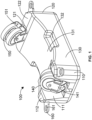
Figure 1 is a schematic view of an element according to a first unclaimed embodiment; -
Figure 2 is a schematic view of an element according to a second unclaimed embodiment; -
Figure 3 is a schematic cross sectional view of an element according to a third embodiment of the present invention; -
Figure 4 is a schematic view of a dock comparing a plurality of the elements depicted inFigure 3 ; and -
Figure 5 is a schematic view of an element according to a fourth aspect of the present invention. - Referring firstly to
Figure 1 , there is depicted anelement 100 for use in a floating dock or platform comprising afirst end portion 110, asecond end portion 120 and anintermediate portion 130. Thefirst end portion 110,second end portion 120 andintermediate portion 130 are all integrally formed, with theintermediate portion 130 lying between theend portions element 100 is a single, continuous structure. The total width of theelement 100 is in the order of 1 m, though other sizes are envisaged. - The
first end portion 110 comprises a firstrotatable support member 140. In this unclaimed embodiment, the firstrotatable support member 140 is a pair of coaxial wheels. The firstrotatable support member 140 is connected to thefirst end portion 110 by afirst mounting arm 141. Thefirst mounting arm 141 is connected to thefirst end portion 110 such that the position of the pair of wheels can be adjusted or changed relative to thefirst end portion 110. Thefirst mounting arm 141 can be extended to adjust the amount the pair of wheels protrudes above the surface of thefirst end portion 110. Additionally, the first mountingarm 141 is connected to thefirst end portion 110 such that the angle of the wheels with respect to thefirst end portion 110 can be adjusted as required. The wheels are connected to the first end portion by the first mountingarm 141 such that the wheels may be continually adjusted between a position where they are fully recessed within an indentation or void 111 in thefirst end portion 110 and a position where the wheels lie completely above atop surface 112 of thefirst end portion 110. Thefirst mounting arm 141 is connected to thefirst end portion 110 such that the user can lock it in position. - The
intermediate portion 130 extends from thefirst end portion 110, connecting it to thesecond end portion 120. Theintermediate portion 130 is substantially cuboid in shape, but has a curvedtop surface 131. Thetop surface 131 curves downwardly from where it connects to thefirst end portion 110 to a low point in at the centre of the intermediate portion. From that point, thetop surface 131 curves back upwards to where it meets thesecond end portion 120. As such, thetop surface 131 of the intermediate portion is substantially C shaped. Theintermediate portion 130 further comprises two intermediate indentations orvoids 132, these intermediate indentations located on opposite sides of thetop surface 131 at the lowest point of the curve. - The
second end portion 120 comprises a secondrotatable support member 150. In this unclaimed embodiment, the secondrotatable support member 150 is a pair of coaxial wheels. The secondrotatable support member 150 is substantially identical to the firstrotatable support member 140. - The second
rotatable support member 150 is connected to thesecond end portion 120 by asecond mounting arm 151. Thesecond mounting arm 151 comprises each and every feature of the first mountingarm 141. As such, each of the capabilities and functions previously described in relation to the first mountingarm 141 is also applicable to thesecond mounting arm 151, with the exception that any changes made in the angle and/or position of the secondrotatable support members 150 by thesecond mounting arm 151 are in relation to thesecond end portion 120, not thefirst end portion 110. Thesecond end portion 120 further includes anindentation 121 andtop surface 122 equivalent to those described in relation to thefirst end portion 110. As such, theelement 100 has two perpendicular planes of symmetry. - The
first end portion 110 and thesecond end portion 120 both compriseconnection tabs 160 at each of their upper external corners such that theelement 100 can be connected to adjacent elements in a modular dock or platform structure. Each of theseconnection tabs 160 comprises aconnection aperture 161 though which a connecting member (not shown) may be inserted to connect adjacent elements together. - In use the first 141 and second 151 mounting arms can be adjusted to independently control the position of the first
rotatable support member 140 and the secondrotatable support member 150 respectively to enable theelement 100 to be used to support a wide range of different shaped and sized watercraft on a floating dock or platform. - Referring now to
Figure 2 , there is depicted anelement 200 according to a second unclaimed embodiment. -
Element 200 again comprises afirst end portion 210, asecond end portion 220 and anintermediate portion 230. As previously described in relation toFigure 1 , thefirst end portion 210,second end portion 220 andintermediate portion 230 are integrally formed such that theelement 200 is a single, continuous structure. Again, the total width of theelement 200 depicted inFigure 2 is around 1 m, although other sizes are envisaged. - The
first end portion 210 comprises a firstrotatable support member 240 in the form of a single wheel mounted on an axle (not shown) within thefirst end portion 210. The single wheel comprises a pneumatic tyre with tread. The wheel lies substantially within anindentation 211 located in thefirst end portion 210, with some of the wheel protruding above atop surface 212 of the first end portion. - The axle is located within a slot within the
indentation 211. The position of the axle within this slot can be adjusted by the user as required, with this change in position of the axle having a concomitant effect of the position of the wheel. As such, movement of the axle can be used to adjust the angle between the wheel and thefirst end portion 210 and the position of the wheel relative to thefirst end portion 210. The axle can be locked into position within the slot to ensure it does not move during use. - The
intermediate portion 230 extends from thefirst end portion 210 in the same fashion as described in relation toFigure 1 . In addition, the intermediate portion comprises all the features of theintermediate portion 130 described inFigure 1 , including twointermediate indentations 232. In the present embodiment, each of theseintermediate indentations 232 contains anintermediate support member 233 in the form of a roller. Each roller has a longitudinal axis that lies substantially parallel with the longitudinal axis of theelement 200. Additionally, each roller lies across the centre of theintermediate portion 230. Each roller protrudes above thetop surface 232 of theintermediate portion 230 and is free to rotate. - The
second end portion 220 comprises a secondrotatable support member 250. The secondrotatable support member 250 is substantially identical to the firstrotatable support member 240 in that it is a pneumatic wheel with a treaded tyre. - The second
rotatable support member 250 is connected to thesecond end portion 220 by a further axle. This further axle is functionally identical to the axle supporting the firstrotatable support member 240. As such, this further axle allows the secondrotatable support structure 250 to move in relation to thesecond end portion 220 exactly as the first axle allows the firstrotatable support structure 240 to move in relation to thefirst end portion 210. As shown, the wheel lies substantially within anindentation 221 located in thefirst end portion 220, with some of the wheel protruding above atop surface 222 of the first end portion. - The
element 200 illustrated inFigure 2 comprisesconnection tabs 260 withconnection apertures 261 identical to those disclosed in relation toFigure 1 . Again, theelement 200 has two perpendicular planes of symmetry. - Once more, in use, the axles can be adjusted to independently control the position of the first
rotatable support member 240 and the secondrotatable support member 250 respectively to enable theelement 200 to be used to support a wide range of different shaped and sized watercraft on a floating dock or platform. - Referring now to
Figure 3 , there is illustrated a cross section of anelement 300 including afirst end portion 310, asecond end portion 320 and anintermediate portion 300. As can be seen inFigure 3 , thefirst end portion 310,second end portion 320 andintermediate portion 330 are all discrete units formed individually and separately from one another. - To form the
complete element 300, thefirst end portion 310 is reversibly connected to theintermediate portion 330, and thesecond end portion 320 is reversibly connected to theintermediate portion 300. As such, theintermediate portion 330 lies between thefirst end portion 310 and thesecond end portion 320. Similarly as described in relation toFigure 2 , this third embodiment of the invention comprises a firstrotatable support member 340 in the form of a single wheel mounted on anaxle 341 within thefirst end portion 310. Again, the single wheel comprises a pneumatic tyre with tread. The wheel lies substantially within anindentation 311 located in thefirst end portion 310, with some of the wheel protruding above atop surface 312 of the first end portion. - The
axle 341 is located within aslot 342 within theindentation 311. As can be seen inFigure 3 , theslot 342 extends substantially the entire height of theindentation 311 and is found in two opposing walls of theindentation 311. As such, theslot 342 is elongate and forms a channel within which theaxle 341 can move relative to theelement 300 to position the firstrotatable support member 340 relative to theelement 300. Theslot 342 is dimensioned such that theaxle 342 fits within, with the length of theaxle 341 being substantially equal to the width of theslot 342. Theaxle 341 can move vertically within theslot 342 until fixed in position by a user, such that the protrusion of the firstrotatable support member 340 above thefirst end portion 310, and the angle of the firstrotatable support member 340 relative to theelement 300, can be adjusted as required by the user. The firstrotatable support member 340 is free to rotate around theaxle 341 without contacting the inner surfaces of theindentation 311. -
Figure 3 further depicts an intermediate indentation in theintermediate portion 332, theintermediate indentation 332 containing anintermediate support member 333 in the form of a roller as outlined in relation toFigure 2 . Thesecond end portion 320 comprises a secondrotatable support member 350. The secondrotatable support member 350 is substantially identical to the firstrotatable support member 340 in that it is a pneumatic wheel with a treaded tyre. - The second
rotatable support member 350 is connected to thesecond end portion 320 by afurther axle 351. This further axle is functionally identical to theaxle 341 supporting the firstrotatable support member 340. As such, thisfurther axle 351 lies within aslot 352 and allows the secondrotatable support structure 350 to move in position and angle relative to thesecond end portion 320 exactly as thefirst axle 341 allows the firstrotatable support structure 340 to move in relation to thefirst end portion 310. - The
element 300 illustrated inFigure 3 again comprisesconnection tabs 360 withconnection apertures 361 identical to those disclosed in relation toFigure 1 andFigure 2 . Again, theelement 300 has two perpendicular planes of symmetry. - Returning to the connection between the
first end portion 310 and theintermediate portion 330, the two are connected by anengagement formation 370. Here, the engagement formation comprises afirst protrusion 375 extending from thefirst end portion 310 and afirst recess 380 located within theintermediate portion 330. Thefirst protrusion 375 is sized such that it fits within thefirst recess 380, and thefirst end portion 310 and theintermediate portion 330 are held together by a friction fit. - The
first protrusion 375 generally tapers down as it extends away from thefirst end portion 310. As such, the cross sectional area of thefirst protrusion 375 reduces as the distance away from the firstrotatable support member 340 increases and thefirst protrusion 375 approaches the centre of theelement 300. - The
first protrusion 375 comprises a first section that tapers substantially continuously and smoothly, and a second portion defined by a sudden decrease in the cross sectional area of the first protrusion. The second portion as illustrated inFigure 3 is in the form of a nodule or knob. Whilst the first portion extends continuously along the length of thefirst end portion 310, the second portion is discontinuous. The second portion may be held more tightly by friction fit within thefirst recess 380 than thefirst portion 375. - The connection between the
second end portion 320 and theintermediate portion 330 is a mirror image of the connection between thefirst end portion 310 and theintermediate portion 330 with asecond engagement formation 377 comprising asecond recess 385 and asecond protrusion 390 comprising first and second portions. Due to the shape of the first 375 and second 390 protrusions and the first 380 and second 385 recesses, theportions element 300 become more securely held together as the weight placed on theelement 300 increases. In other words, theprotrusions -
Figure 4 depicts a floatingdock 1000 or platform including a plurality of theelements 300 ofFigure 3 . Three of theelements 300 are connected together in series such that the rotatable members located on each portion are aligned with one another. In this configuration, theelements 300 form a channel up which a watercraft may be driven or dragged, supported by the rotatable support members. As previously described, the precise position of the rotatable support members located with the first end portion and second end portion of eachelement 300 may be adjusted to adapt the dock for different size watercraft. - Additionally, the
dock 100 includes three further elements 400 equivalent toelement 300 apart from the removal of the intermediate portion. As such, each of these further elements 400 comprises afirst end portion 410 and asecond end portion 420 with a channel or gap between them. The elements 400 are positioned such that theirfirst end portions 410 align with thefirst end portions 310 ofelements 300, and such that thesecond end portions 420 align with thesecond end portions 320 ofelements 300. As such, the channel or gap present in the elements 400 align with theintermediate portions 330 of the elements 300.The channel may therefore allow the passage of a keel as a watercraft is positioned on to the floatingdock 1000. -
Figure 5 depicts anelement 500, again including afirst end portion 510, asecond end portion 520 and an intermediate portion as described in relation toFigure 3 . Whilst not all the feature of this embodiment of the invention are illustrated inFigure 5 ,element 500 is substantially identical toelement 300 with the exception of the connection between thefirst end portion 510 and theintermediate portion 530 and the connection between thesecond end portion 520 and theintermediate portion 530. - Turning firstly towards the connection between the
first end portion 510 and theintermediate portion 530, the two are connected by anengagement formation 570. Here, the engagement formation comprises afirst protrusion 575 extending from thefirst end portion 510 and afirst recess 580 located within theintermediate portion 530. Thefirst protrusion 575 is sized such that it fits within thefirst recess 580, and thefirst end portion 510 and theintermediate portion 530 are held together by a friction fit. - The
first protrusion 575 generally tapers down as it extends away from thefirst end portion 510. As such, the cross sectional area of thefirst protrusion 575 reduces as thefirst protrusion 575 approaches the centre of theelement 500. - The
first recess 580 comprises a central protrusion in the form of aknob 590. Theknob 590 extends away from theintermediate portion 530, into thefirst recess 580 towards thefirst end portion 510. Theknob 590 is sized to fit within a corresponding cavity within thefirst protrusion 575 where it is held by a friction or interference fit to secure thefirst end portion 510 and theintermediate portion 530 together, - The
second end portion 520 is connected to theintermediate portion 530 in an equivalent manner. The connection between thesecond end portion 520 and theintermediate portion 530 is a mirror image of the connection between thefirst end portion 510 and theintermediate portion 530 with asecond engagement formation 577 comprising asecond recess 585 and asecond protrusion 590. Again, thesecond recess 585 comprises a central protrusion in the form of a knob. The knob extends away from theintermediate portion 530, into thesecond recess 585 towards thesecond end portion 520. The knob is sized to fit within a corresponding cavity within the second protrusion 595 where it is held by a friction or interference fit to secure thesecond end portion 520 and theintermediate portion 530 together, - Locating the knobs of the first 570 and second 577 engagement formations on the intermediate portion may be advantageous as it increases the width of the central channel between the
first end portion 510 and thesecond end portion 520 when theintermediate portion 530 is removed as illustrated inFigure 4 . Additionally, the incorporation of rotatable elements within the cavities may be useful in easing the passage of a watercraft on to a floating dock.
Claims (11)
- An element (100, 200, 300, 400, 500) for use in a floating dock, said element (100, 200, 300, 400, 500) comprising a first rotatable support member (140, 240, 340); whereinsaid first rotatable support member (140, 240, 340) is mounted on said element (100, 200, 300, 400, 500) such that the position of said first rotatable support member (140, 240, 340) relative to said element (100, 200, 300, 400, 500) can be varied by a user,said element (100, 200, 300, 400, 500) further comprising a second rotatable support member (150, 250, 350),wherein said element (100, 200, 300, 400, 500) comprises:a first end portion (110, 210, 310, 410, 510), wherein said first rotatable support member (140, 240, 340) is mounted on said first end portion (110, 210, 310, 410, 510);a second end portion (120, 220, 320, 420, 520), wherein said second rotatable support member (150, 250, 350) is mounted on said second end portion (120, 220, 320, 420, 520); andan intermediate portion (130, 230, 330) extending between said first end portion (110, 210, 310, 410, 510) and said second end portion (120, 220, 320, 420, 520),characterised in thatsaid intermediate portion (130, 230, 330) is connected to said first end portion (110, 210, 310, 410, 510) by a first engagement formation.
- The element (100, 200, 300, 400, 500) of claim 1, wherein the height of said first rotatable support member (140, 240, 340) relative to said element (100, 200, 300, 400, 500) can be varied by a user.
- The element (100, 200, 300, 400, 500) of claim 1 or claim 2, wherein the angle between said first rotatable support member (140, 240, 340) and said element (100, 200, 300, 400, 500) can be varied by a user.
- The element (100, 200, 300, 400, 500) of claim 1, wherein said second rotatable support member (150, 250, 350) is mounted on said element (100, 200, 300, 400, 500) such that the position of said second rotatable support member (150, 250, 350) relative to said element (100, 200, 300, 400, 500) can be varied by a user.
- The element (100, 200, 300, 400, 500) of claim 4, wherein the height of said second rotatable support member (150, 250, 350) relative to said element (100, 200, 300, 400, 500) can be varied by a user.
- The element (100, 200, 300, 400, 500) of claim 4 or claim 5, wherein the angle between said second rotatable support member (150, 250, 350) and said element (100, 200, 300, 400, 500) can be varied by a user.
- The element (100, 200, 300, 400, 500) of claim 1, wherein said first engagement formation comprises a first protrusion (375, 575) extending from said first end portion (110, 210, 310, 410, 510) into a first recess in said intermediate portion (130, 230, 330), where said first recess is sized to fit said first protrusion (375, 575).
- The element (100, 200, 300, 400, 500) of claim 1 or claim 7, wherein said first engagement formation comprises a primary tapered portion and a secondary nodule.
- The element (100, 200, 300, 400, 500) of any one of claims 1 to 8, wherein said intermediate portion (130, 230, 330) is connected to said second end portion (120, 220, 320, 420, 520) by a second engagement formation (377, 577).
- The element (100, 200, 300, 400, 500) of claim 9, wherein said second engagement formation (377, 577) comprises a second protrusion (390, 590) extending from said second end portion (120, 220, 320, 420, 520) into a second recess (385, 585) in said intermediate portion (130, 230, 330), where said second recess (385, 585) is sized to fit said second protrusion (390 590).
- A floating dock, said floating dock comprising at least one element (100, 200, 300, 400, 500) of any one preceding claim.
Applications Claiming Priority (1)
| Application Number | Priority Date | Filing Date | Title |
|---|---|---|---|
| GB2006446.5A GB2594513B (en) | 2020-05-01 | 2020-05-01 | Element for a floating dock and a floating dock |
Publications (2)
| Publication Number | Publication Date |
|---|---|
| EP3904197A1 EP3904197A1 (en) | 2021-11-03 |
| EP3904197B1 true EP3904197B1 (en) | 2023-07-26 |
Family
ID=71080623
Family Applications (1)
| Application Number | Title | Priority Date | Filing Date |
|---|---|---|---|
| EP21170285.7A Active EP3904197B1 (en) | 2020-05-01 | 2021-04-23 | Element for a floating dock and a floating dock |
Country Status (3)
| Country | Link |
|---|---|
| US (1) | US12077267B2 (en) |
| EP (1) | EP3904197B1 (en) |
| GB (1) | GB2594513B (en) |
Families Citing this family (3)
| Publication number | Priority date | Publication date | Assignee | Title |
|---|---|---|---|---|
| GB2594513B (en) * | 2020-05-01 | 2024-04-10 | Marine Ip Ltd | Element for a floating dock and a floating dock |
| US20220063779A1 (en) * | 2020-09-02 | 2022-03-03 | Innovative Outdoor Solutions, Inc. | Wheel for floating watercraft port |
| US11746813B2 (en) * | 2020-10-19 | 2023-09-05 | Bruce Nelson | Load conveyance system for modular floating platforms |
Family Cites Families (12)
| Publication number | Priority date | Publication date | Assignee | Title |
|---|---|---|---|---|
| US4714375A (en) * | 1984-11-13 | 1987-12-22 | Levitator, Inc. | Seaplane and dock lift |
| ES2402443T3 (en) * | 2004-02-06 | 2013-05-03 | E-Z Dock, Inc. | Floating dock for boats that climb above |
| US7100527B2 (en) * | 2004-09-01 | 2006-09-05 | Robert Alexander Munro | Watercraft mooring device |
| WO2007109808A2 (en) * | 2006-03-23 | 2007-09-27 | Sunstream Corporation | Failsafe watercraft lift with convertible leveling system |
| GB2509502B (en) * | 2013-01-03 | 2015-12-09 | Marine Ip Ltd | Floating dock |
| US20160145822A1 (en) * | 2014-11-21 | 2016-05-26 | Paul R. Gerst | Compressible roller for use in stabilizing a floating dock |
| US10315738B2 (en) * | 2016-11-30 | 2019-06-11 | E-Z-Dock, Inc. | Small watercraft launch |
| US10300996B2 (en) * | 2017-03-13 | 2019-05-28 | Cellofoam North America, Inc. | Self-adjusting drive-on floating dock |
| LU100522B1 (en) * | 2017-11-27 | 2019-05-27 | Thyssenkrupp Marine Sys Gmbh | Receiving device and receiving method with conveyor belts for a watercraft |
| JP6928381B2 (en) * | 2018-08-03 | 2021-09-01 | 株式会社ニシエフ | Floating device |
| GB2594513B (en) * | 2020-05-01 | 2024-04-10 | Marine Ip Ltd | Element for a floating dock and a floating dock |
| GB2610418B (en) * | 2021-09-03 | 2023-12-20 | Millorit Andrew | Floatation apparatus and method of operating the same |
-
2020
- 2020-05-01 GB GB2006446.5A patent/GB2594513B/en not_active Expired - Fee Related
-
2021
- 2021-04-23 EP EP21170285.7A patent/EP3904197B1/en active Active
- 2021-04-28 US US17/242,558 patent/US12077267B2/en active Active
Also Published As
| Publication number | Publication date |
|---|---|
| GB2594513B (en) | 2024-04-10 |
| EP3904197A1 (en) | 2021-11-03 |
| GB202006446D0 (en) | 2020-06-17 |
| US12077267B2 (en) | 2024-09-03 |
| US20210347452A1 (en) | 2021-11-11 |
| GB2594513A (en) | 2021-11-03 |
Similar Documents
| Publication | Publication Date | Title |
|---|---|---|
| EP3904197A1 (en) | Element for a floating dock and a floating dock | |
| EP1462358B1 (en) | Mooring apparatus suited to a tanker transporting liquid gas | |
| US9656731B2 (en) | Personal water craft drive-on dock | |
| WO2014106743A1 (en) | Floating dock | |
| EP2661392B1 (en) | T.d.d (tube docking device) | |
| US5636585A (en) | Sailboat with hydrofoil members | |
| KR102914805B1 (en) | Floating pier with ship collision prevention and position maintenance function | |
| CN112046700B (en) | Combined roll-on/roll-off ferry | |
| US3819136A (en) | Marine antenna mount | |
| CN106794888A (en) | Floating platform with pivoting keel skirt | |
| US5921195A (en) | Apparatus for coastal navigation and self rescue | |
| US20030154895A1 (en) | Road towed ferry | |
| CN102046459B (en) | Devices for Sectional Ship Ramps | |
| JP2016534921A (en) | Roll-on / roll-off ferry and multi-lamp wharf | |
| WO2020248012A1 (en) | A variable beam vessel | |
| US9725137B2 (en) | Semisubmersible with five-sided columns | |
| CN211711010U (en) | Deformable deck structure and ship | |
| CN212605705U (en) | Combined roll-on/roll-off ferryboat | |
| KR200367328Y1 (en) | Wharf structure for berthing of ship | |
| KR20190059650A (en) | Intergrated tug-barge system | |
| KR20140098877A (en) | Transfer Apparatus for Heavy Material | |
| CA2306945C (en) | Passive stabilizer for floating petroleum-production systems | |
| CN213768904U (en) | High bulwark ship dock boarding ladder | |
| US10427767B1 (en) | Locking system for assisting and supporting an actuator of a trim-tab of a watercraft in the desired mode | |
| CN113715969B (en) | Shuttle tanker dynamic positioning method |
Legal Events
| Date | Code | Title | Description |
|---|---|---|---|
| PUAI | Public reference made under article 153(3) epc to a published international application that has entered the european phase |
Free format text: ORIGINAL CODE: 0009012 |
|
| STAA | Information on the status of an ep patent application or granted ep patent |
Free format text: STATUS: THE APPLICATION HAS BEEN PUBLISHED |
|
| AK | Designated contracting states |
Kind code of ref document: A1 Designated state(s): AL AT BE BG CH CY CZ DE DK EE ES FI FR GB GR HR HU IE IS IT LI LT LU LV MC MK MT NL NO PL PT RO RS SE SI SK SM TR |
|
| B565 | Issuance of search results under rule 164(2) epc |
Effective date: 20210920 |
|
| STAA | Information on the status of an ep patent application or granted ep patent |
Free format text: STATUS: REQUEST FOR EXAMINATION WAS MADE |
|
| 17P | Request for examination filed |
Effective date: 20220429 |
|
| RBV | Designated contracting states (corrected) |
Designated state(s): AL AT BE BG CH CY CZ DE DK EE ES FI FR GB GR HR HU IE IS IT LI LT LU LV MC MK MT NL NO PL PT RO RS SE SI SK SM TR |
|
| RIC1 | Information provided on ipc code assigned before grant |
Ipc: B63C 1/04 19680901AFI20230106BHEP |
|
| GRAP | Despatch of communication of intention to grant a patent |
Free format text: ORIGINAL CODE: EPIDOSNIGR1 |
|
| STAA | Information on the status of an ep patent application or granted ep patent |
Free format text: STATUS: GRANT OF PATENT IS INTENDED |
|
| INTG | Intention to grant announced |
Effective date: 20230223 |
|
| GRAS | Grant fee paid |
Free format text: ORIGINAL CODE: EPIDOSNIGR3 |
|
| GRAA | (expected) grant |
Free format text: ORIGINAL CODE: 0009210 |
|
| STAA | Information on the status of an ep patent application or granted ep patent |
Free format text: STATUS: THE PATENT HAS BEEN GRANTED |
|
| AK | Designated contracting states |
Kind code of ref document: B1 Designated state(s): AL AT BE BG CH CY CZ DE DK EE ES FI FR GB GR HR HU IE IS IT LI LT LU LV MC MK MT NL NO PL PT RO RS SE SI SK SM TR |
|
| REG | Reference to a national code |
Ref country code: CH Ref legal event code: EP |
|
| REG | Reference to a national code |
Ref country code: IE Ref legal event code: FG4D |
|
| REG | Reference to a national code |
Ref country code: DE Ref legal event code: R096 Ref document number: 602021003719 Country of ref document: DE |
|
| REG | Reference to a national code |
Ref country code: NL Ref legal event code: FP |
|
| REG | Reference to a national code |
Ref country code: LT Ref legal event code: MG9D |
|
| REG | Reference to a national code |
Ref country code: SE Ref legal event code: TRGR |
|
| REG | Reference to a national code |
Ref country code: AT Ref legal event code: MK05 Ref document number: 1591674 Country of ref document: AT Kind code of ref document: T Effective date: 20230726 |
|
| PG25 | Lapsed in a contracting state [announced via postgrant information from national office to epo] |
Ref country code: GR Free format text: LAPSE BECAUSE OF FAILURE TO SUBMIT A TRANSLATION OF THE DESCRIPTION OR TO PAY THE FEE WITHIN THE PRESCRIBED TIME-LIMIT Effective date: 20231027 |
|
| PG25 | Lapsed in a contracting state [announced via postgrant information from national office to epo] |
Ref country code: IS Free format text: LAPSE BECAUSE OF FAILURE TO SUBMIT A TRANSLATION OF THE DESCRIPTION OR TO PAY THE FEE WITHIN THE PRESCRIBED TIME-LIMIT Effective date: 20231126 |
|
| PG25 | Lapsed in a contracting state [announced via postgrant information from national office to epo] |
Ref country code: RS Free format text: LAPSE BECAUSE OF FAILURE TO SUBMIT A TRANSLATION OF THE DESCRIPTION OR TO PAY THE FEE WITHIN THE PRESCRIBED TIME-LIMIT Effective date: 20230726 Ref country code: PT Free format text: LAPSE BECAUSE OF FAILURE TO SUBMIT A TRANSLATION OF THE DESCRIPTION OR TO PAY THE FEE WITHIN THE PRESCRIBED TIME-LIMIT Effective date: 20231127 Ref country code: NO Free format text: LAPSE BECAUSE OF FAILURE TO SUBMIT A TRANSLATION OF THE DESCRIPTION OR TO PAY THE FEE WITHIN THE PRESCRIBED TIME-LIMIT Effective date: 20231026 Ref country code: LV Free format text: LAPSE BECAUSE OF FAILURE TO SUBMIT A TRANSLATION OF THE DESCRIPTION OR TO PAY THE FEE WITHIN THE PRESCRIBED TIME-LIMIT Effective date: 20230726 Ref country code: LT Free format text: LAPSE BECAUSE OF FAILURE TO SUBMIT A TRANSLATION OF THE DESCRIPTION OR TO PAY THE FEE WITHIN THE PRESCRIBED TIME-LIMIT Effective date: 20230726 Ref country code: IS Free format text: LAPSE BECAUSE OF FAILURE TO SUBMIT A TRANSLATION OF THE DESCRIPTION OR TO PAY THE FEE WITHIN THE PRESCRIBED TIME-LIMIT Effective date: 20231126 Ref country code: HR Free format text: LAPSE BECAUSE OF FAILURE TO SUBMIT A TRANSLATION OF THE DESCRIPTION OR TO PAY THE FEE WITHIN THE PRESCRIBED TIME-LIMIT Effective date: 20230726 Ref country code: GR Free format text: LAPSE BECAUSE OF FAILURE TO SUBMIT A TRANSLATION OF THE DESCRIPTION OR TO PAY THE FEE WITHIN THE PRESCRIBED TIME-LIMIT Effective date: 20231027 Ref country code: FI Free format text: LAPSE BECAUSE OF FAILURE TO SUBMIT A TRANSLATION OF THE DESCRIPTION OR TO PAY THE FEE WITHIN THE PRESCRIBED TIME-LIMIT Effective date: 20230726 Ref country code: AT Free format text: LAPSE BECAUSE OF FAILURE TO SUBMIT A TRANSLATION OF THE DESCRIPTION OR TO PAY THE FEE WITHIN THE PRESCRIBED TIME-LIMIT Effective date: 20230726 |
|
| PG25 | Lapsed in a contracting state [announced via postgrant information from national office to epo] |
Ref country code: PL Free format text: LAPSE BECAUSE OF FAILURE TO SUBMIT A TRANSLATION OF THE DESCRIPTION OR TO PAY THE FEE WITHIN THE PRESCRIBED TIME-LIMIT Effective date: 20230726 |
|
| PG25 | Lapsed in a contracting state [announced via postgrant information from national office to epo] |
Ref country code: ES Free format text: LAPSE BECAUSE OF FAILURE TO SUBMIT A TRANSLATION OF THE DESCRIPTION OR TO PAY THE FEE WITHIN THE PRESCRIBED TIME-LIMIT Effective date: 20230726 |
|
| REG | Reference to a national code |
Ref country code: DE Ref legal event code: R097 Ref document number: 602021003719 Country of ref document: DE |
|
| PG25 | Lapsed in a contracting state [announced via postgrant information from national office to epo] |
Ref country code: SM Free format text: LAPSE BECAUSE OF FAILURE TO SUBMIT A TRANSLATION OF THE DESCRIPTION OR TO PAY THE FEE WITHIN THE PRESCRIBED TIME-LIMIT Effective date: 20230726 Ref country code: RO Free format text: LAPSE BECAUSE OF FAILURE TO SUBMIT A TRANSLATION OF THE DESCRIPTION OR TO PAY THE FEE WITHIN THE PRESCRIBED TIME-LIMIT Effective date: 20230726 Ref country code: ES Free format text: LAPSE BECAUSE OF FAILURE TO SUBMIT A TRANSLATION OF THE DESCRIPTION OR TO PAY THE FEE WITHIN THE PRESCRIBED TIME-LIMIT Effective date: 20230726 Ref country code: EE Free format text: LAPSE BECAUSE OF FAILURE TO SUBMIT A TRANSLATION OF THE DESCRIPTION OR TO PAY THE FEE WITHIN THE PRESCRIBED TIME-LIMIT Effective date: 20230726 Ref country code: DK Free format text: LAPSE BECAUSE OF FAILURE TO SUBMIT A TRANSLATION OF THE DESCRIPTION OR TO PAY THE FEE WITHIN THE PRESCRIBED TIME-LIMIT Effective date: 20230726 Ref country code: CZ Free format text: LAPSE BECAUSE OF FAILURE TO SUBMIT A TRANSLATION OF THE DESCRIPTION OR TO PAY THE FEE WITHIN THE PRESCRIBED TIME-LIMIT Effective date: 20230726 Ref country code: SK Free format text: LAPSE BECAUSE OF FAILURE TO SUBMIT A TRANSLATION OF THE DESCRIPTION OR TO PAY THE FEE WITHIN THE PRESCRIBED TIME-LIMIT Effective date: 20230726 |
|
| PGFP | Annual fee paid to national office [announced via postgrant information from national office to epo] |
Ref country code: NL Payment date: 20240423 Year of fee payment: 4 |
|
| PLBE | No opposition filed within time limit |
Free format text: ORIGINAL CODE: 0009261 |
|
| STAA | Information on the status of an ep patent application or granted ep patent |
Free format text: STATUS: NO OPPOSITION FILED WITHIN TIME LIMIT |
|
| 26N | No opposition filed |
Effective date: 20240429 |
|
| PGFP | Annual fee paid to national office [announced via postgrant information from national office to epo] |
Ref country code: IE Payment date: 20240425 Year of fee payment: 4 |
|
| PGFP | Annual fee paid to national office [announced via postgrant information from national office to epo] |
Ref country code: DE Payment date: 20240430 Year of fee payment: 4 |
|
| PGFP | Annual fee paid to national office [announced via postgrant information from national office to epo] |
Ref country code: CH Payment date: 20240501 Year of fee payment: 4 |
|
| PG25 | Lapsed in a contracting state [announced via postgrant information from national office to epo] |
Ref country code: SI Free format text: LAPSE BECAUSE OF FAILURE TO SUBMIT A TRANSLATION OF THE DESCRIPTION OR TO PAY THE FEE WITHIN THE PRESCRIBED TIME-LIMIT Effective date: 20230726 |
|
| PGFP | Annual fee paid to national office [announced via postgrant information from national office to epo] |
Ref country code: IT Payment date: 20240430 Year of fee payment: 4 Ref country code: FR Payment date: 20240426 Year of fee payment: 4 |
|
| PGFP | Annual fee paid to national office [announced via postgrant information from national office to epo] |
Ref country code: SE Payment date: 20240429 Year of fee payment: 4 |
|
| PG25 | Lapsed in a contracting state [announced via postgrant information from national office to epo] |
Ref country code: BG Free format text: LAPSE BECAUSE OF FAILURE TO SUBMIT A TRANSLATION OF THE DESCRIPTION OR TO PAY THE FEE WITHIN THE PRESCRIBED TIME-LIMIT Effective date: 20230726 |
|
| PG25 | Lapsed in a contracting state [announced via postgrant information from national office to epo] |
Ref country code: MC Free format text: LAPSE BECAUSE OF FAILURE TO SUBMIT A TRANSLATION OF THE DESCRIPTION OR TO PAY THE FEE WITHIN THE PRESCRIBED TIME-LIMIT Effective date: 20230726 |
|
| PG25 | Lapsed in a contracting state [announced via postgrant information from national office to epo] |
Ref country code: MC Free format text: LAPSE BECAUSE OF FAILURE TO SUBMIT A TRANSLATION OF THE DESCRIPTION OR TO PAY THE FEE WITHIN THE PRESCRIBED TIME-LIMIT Effective date: 20230726 Ref country code: BG Free format text: LAPSE BECAUSE OF FAILURE TO SUBMIT A TRANSLATION OF THE DESCRIPTION OR TO PAY THE FEE WITHIN THE PRESCRIBED TIME-LIMIT Effective date: 20230726 |
|
| PG25 | Lapsed in a contracting state [announced via postgrant information from national office to epo] |
Ref country code: LU Free format text: LAPSE BECAUSE OF NON-PAYMENT OF DUE FEES Effective date: 20240423 |
|
| REG | Reference to a national code |
Ref country code: BE Ref legal event code: MM Effective date: 20240430 |
|
| PG25 | Lapsed in a contracting state [announced via postgrant information from national office to epo] |
Ref country code: LU Free format text: LAPSE BECAUSE OF NON-PAYMENT OF DUE FEES Effective date: 20240423 |
|
| PG25 | Lapsed in a contracting state [announced via postgrant information from national office to epo] |
Ref country code: BE Free format text: LAPSE BECAUSE OF NON-PAYMENT OF DUE FEES Effective date: 20240430 |
|
| PG25 | Lapsed in a contracting state [announced via postgrant information from national office to epo] |
Ref country code: BE Free format text: LAPSE BECAUSE OF NON-PAYMENT OF DUE FEES Effective date: 20240430 |
|
| PG25 | Lapsed in a contracting state [announced via postgrant information from national office to epo] |
Ref country code: CY Free format text: LAPSE BECAUSE OF FAILURE TO SUBMIT A TRANSLATION OF THE DESCRIPTION OR TO PAY THE FEE WITHIN THE PRESCRIBED TIME-LIMIT; INVALID AB INITIO Effective date: 20210423 |
|
| PG25 | Lapsed in a contracting state [announced via postgrant information from national office to epo] |
Ref country code: HU Free format text: LAPSE BECAUSE OF FAILURE TO SUBMIT A TRANSLATION OF THE DESCRIPTION OR TO PAY THE FEE WITHIN THE PRESCRIBED TIME-LIMIT; INVALID AB INITIO Effective date: 20210423 |
|
| REG | Reference to a national code |
Ref country code: DE Ref legal event code: R119 Ref document number: 602021003719 Country of ref document: DE |
|
| REG | Reference to a national code |
Ref country code: CH Ref legal event code: H13 Free format text: ST27 STATUS EVENT CODE: U-0-0-H10-H13 (AS PROVIDED BY THE NATIONAL OFFICE) Effective date: 20251125 |
|
| REG | Reference to a national code |
Ref country code: SE Ref legal event code: EUG |
|
| REG | Reference to a national code |
Ref country code: NL Ref legal event code: MM Effective date: 20250501 |
|
| GBPC | Gb: european patent ceased through non-payment of renewal fee |
Effective date: 20250423 |
|
| PG25 | Lapsed in a contracting state [announced via postgrant information from national office to epo] |
Ref country code: DE Free format text: LAPSE BECAUSE OF NON-PAYMENT OF DUE FEES Effective date: 20251104 |
|
| PG25 | Lapsed in a contracting state [announced via postgrant information from national office to epo] |
Ref country code: GB Free format text: LAPSE BECAUSE OF NON-PAYMENT OF DUE FEES Effective date: 20250423 |
|
| PG25 | Lapsed in a contracting state [announced via postgrant information from national office to epo] |
Ref country code: NL Free format text: LAPSE BECAUSE OF NON-PAYMENT OF DUE FEES Effective date: 20250501 Ref country code: FR Free format text: LAPSE BECAUSE OF NON-PAYMENT OF DUE FEES Effective date: 20250430 |
|
| PG25 | Lapsed in a contracting state [announced via postgrant information from national office to epo] |
Ref country code: CH Free format text: LAPSE BECAUSE OF NON-PAYMENT OF DUE FEES Effective date: 20250430 |
|
| PG25 | Lapsed in a contracting state [announced via postgrant information from national office to epo] |
Ref country code: SE Free format text: LAPSE BECAUSE OF NON-PAYMENT OF DUE FEES Effective date: 20250424 |
|
| PG25 | Lapsed in a contracting state [announced via postgrant information from national office to epo] |
Ref country code: IE Free format text: LAPSE BECAUSE OF NON-PAYMENT OF DUE FEES Effective date: 20250423 |
|
| PG25 | Lapsed in a contracting state [announced via postgrant information from national office to epo] |
Ref country code: IT Free format text: LAPSE BECAUSE OF NON-PAYMENT OF DUE FEES Effective date: 20250423 |
|
| PG25 | Lapsed in a contracting state [announced via postgrant information from national office to epo] |
Ref country code: TR Free format text: LAPSE BECAUSE OF FAILURE TO SUBMIT A TRANSLATION OF THE DESCRIPTION OR TO PAY THE FEE WITHIN THE PRESCRIBED TIME-LIMIT Effective date: 20230726 |