EP3904196A1 - Ship - Google Patents
Ship Download PDFInfo
- Publication number
- EP3904196A1 EP3904196A1 EP19906121.9A EP19906121A EP3904196A1 EP 3904196 A1 EP3904196 A1 EP 3904196A1 EP 19906121 A EP19906121 A EP 19906121A EP 3904196 A1 EP3904196 A1 EP 3904196A1
- Authority
- EP
- European Patent Office
- Prior art keywords
- outer shell
- vacuum
- main part
- dome
- exhaust pipe
- Prior art date
- Legal status (The legal status is an assumption and is not a legal conclusion. Google has not performed a legal analysis and makes no representation as to the accuracy of the status listed.)
- Granted
Links
Images



Classifications
-
- B—PERFORMING OPERATIONS; TRANSPORTING
- B63—SHIPS OR OTHER WATERBORNE VESSELS; RELATED EQUIPMENT
- B63B—SHIPS OR OTHER WATERBORNE VESSELS; EQUIPMENT FOR SHIPPING
- B63B25/00—Load-accommodating arrangements, e.g. stowing, trimming; Vessels characterised thereby
- B63B25/02—Load-accommodating arrangements, e.g. stowing, trimming; Vessels characterised thereby for bulk goods
- B63B25/08—Load-accommodating arrangements, e.g. stowing, trimming; Vessels characterised thereby for bulk goods fluid
- B63B25/12—Load-accommodating arrangements, e.g. stowing, trimming; Vessels characterised thereby for bulk goods fluid closed
- B63B25/16—Load-accommodating arrangements, e.g. stowing, trimming; Vessels characterised thereby for bulk goods fluid closed heat-insulated
-
- F—MECHANICAL ENGINEERING; LIGHTING; HEATING; WEAPONS; BLASTING
- F17—STORING OR DISTRIBUTING GASES OR LIQUIDS
- F17C—VESSELS FOR CONTAINING OR STORING COMPRESSED, LIQUEFIED OR SOLIDIFIED GASES; FIXED-CAPACITY GAS-HOLDERS; FILLING VESSELS WITH, OR DISCHARGING FROM VESSELS, COMPRESSED, LIQUEFIED, OR SOLIDIFIED GASES
- F17C13/00—Details of vessels or of the filling or discharging of vessels
- F17C13/08—Mounting arrangements for vessels
- F17C13/082—Mounting arrangements for vessels for large sea-borne storage vessels
-
- F—MECHANICAL ENGINEERING; LIGHTING; HEATING; WEAPONS; BLASTING
- F17—STORING OR DISTRIBUTING GASES OR LIQUIDS
- F17C—VESSELS FOR CONTAINING OR STORING COMPRESSED, LIQUEFIED OR SOLIDIFIED GASES; FIXED-CAPACITY GAS-HOLDERS; FILLING VESSELS WITH, OR DISCHARGING FROM VESSELS, COMPRESSED, LIQUEFIED, OR SOLIDIFIED GASES
- F17C3/00—Vessels not under pressure
- F17C3/02—Vessels not under pressure with provision for thermal insulation
- F17C3/08—Vessels not under pressure with provision for thermal insulation by vacuum spaces, e.g. Dewar flask
-
- B—PERFORMING OPERATIONS; TRANSPORTING
- B63—SHIPS OR OTHER WATERBORNE VESSELS; RELATED EQUIPMENT
- B63B—SHIPS OR OTHER WATERBORNE VESSELS; EQUIPMENT FOR SHIPPING
- B63B25/00—Load-accommodating arrangements, e.g. stowing, trimming; Vessels characterised thereby
- B63B25/02—Load-accommodating arrangements, e.g. stowing, trimming; Vessels characterised thereby for bulk goods
- B63B25/08—Load-accommodating arrangements, e.g. stowing, trimming; Vessels characterised thereby for bulk goods fluid
- B63B2025/087—Load-accommodating arrangements, e.g. stowing, trimming; Vessels characterised thereby for bulk goods fluid comprising self-contained tanks installed in the ship structure as separate units
-
- F—MECHANICAL ENGINEERING; LIGHTING; HEATING; WEAPONS; BLASTING
- F17—STORING OR DISTRIBUTING GASES OR LIQUIDS
- F17C—VESSELS FOR CONTAINING OR STORING COMPRESSED, LIQUEFIED OR SOLIDIFIED GASES; FIXED-CAPACITY GAS-HOLDERS; FILLING VESSELS WITH, OR DISCHARGING FROM VESSELS, COMPRESSED, LIQUEFIED, OR SOLIDIFIED GASES
- F17C2201/00—Vessel construction, in particular geometry, arrangement or size
- F17C2201/01—Shape
- F17C2201/0104—Shape cylindrical
-
- F—MECHANICAL ENGINEERING; LIGHTING; HEATING; WEAPONS; BLASTING
- F17—STORING OR DISTRIBUTING GASES OR LIQUIDS
- F17C—VESSELS FOR CONTAINING OR STORING COMPRESSED, LIQUEFIED OR SOLIDIFIED GASES; FIXED-CAPACITY GAS-HOLDERS; FILLING VESSELS WITH, OR DISCHARGING FROM VESSELS, COMPRESSED, LIQUEFIED, OR SOLIDIFIED GASES
- F17C2201/00—Vessel construction, in particular geometry, arrangement or size
- F17C2201/01—Shape
- F17C2201/0104—Shape cylindrical
- F17C2201/0109—Shape cylindrical with exteriorly curved end-piece
-
- F—MECHANICAL ENGINEERING; LIGHTING; HEATING; WEAPONS; BLASTING
- F17—STORING OR DISTRIBUTING GASES OR LIQUIDS
- F17C—VESSELS FOR CONTAINING OR STORING COMPRESSED, LIQUEFIED OR SOLIDIFIED GASES; FIXED-CAPACITY GAS-HOLDERS; FILLING VESSELS WITH, OR DISCHARGING FROM VESSELS, COMPRESSED, LIQUEFIED, OR SOLIDIFIED GASES
- F17C2201/00—Vessel construction, in particular geometry, arrangement or size
- F17C2201/03—Orientation
- F17C2201/035—Orientation with substantially horizontal main axis
-
- F—MECHANICAL ENGINEERING; LIGHTING; HEATING; WEAPONS; BLASTING
- F17—STORING OR DISTRIBUTING GASES OR LIQUIDS
- F17C—VESSELS FOR CONTAINING OR STORING COMPRESSED, LIQUEFIED OR SOLIDIFIED GASES; FIXED-CAPACITY GAS-HOLDERS; FILLING VESSELS WITH, OR DISCHARGING FROM VESSELS, COMPRESSED, LIQUEFIED, OR SOLIDIFIED GASES
- F17C2201/00—Vessel construction, in particular geometry, arrangement or size
- F17C2201/05—Size
- F17C2201/052—Size large (>1000 m3)
-
- F—MECHANICAL ENGINEERING; LIGHTING; HEATING; WEAPONS; BLASTING
- F17—STORING OR DISTRIBUTING GASES OR LIQUIDS
- F17C—VESSELS FOR CONTAINING OR STORING COMPRESSED, LIQUEFIED OR SOLIDIFIED GASES; FIXED-CAPACITY GAS-HOLDERS; FILLING VESSELS WITH, OR DISCHARGING FROM VESSELS, COMPRESSED, LIQUEFIED, OR SOLIDIFIED GASES
- F17C2203/00—Vessel construction, in particular walls or details thereof
- F17C2203/03—Thermal insulations
- F17C2203/0391—Thermal insulations by vacuum
-
- F—MECHANICAL ENGINEERING; LIGHTING; HEATING; WEAPONS; BLASTING
- F17—STORING OR DISTRIBUTING GASES OR LIQUIDS
- F17C—VESSELS FOR CONTAINING OR STORING COMPRESSED, LIQUEFIED OR SOLIDIFIED GASES; FIXED-CAPACITY GAS-HOLDERS; FILLING VESSELS WITH, OR DISCHARGING FROM VESSELS, COMPRESSED, LIQUEFIED, OR SOLIDIFIED GASES
- F17C2203/00—Vessel construction, in particular walls or details thereof
- F17C2203/06—Materials for walls or layers thereof; Properties or structures of walls or their materials
- F17C2203/0602—Wall structures; Special features thereof
- F17C2203/0612—Wall structures
- F17C2203/0626—Multiple walls
- F17C2203/0629—Two walls
-
- F—MECHANICAL ENGINEERING; LIGHTING; HEATING; WEAPONS; BLASTING
- F17—STORING OR DISTRIBUTING GASES OR LIQUIDS
- F17C—VESSELS FOR CONTAINING OR STORING COMPRESSED, LIQUEFIED OR SOLIDIFIED GASES; FIXED-CAPACITY GAS-HOLDERS; FILLING VESSELS WITH, OR DISCHARGING FROM VESSELS, COMPRESSED, LIQUEFIED, OR SOLIDIFIED GASES
- F17C2205/00—Vessel construction, in particular mounting arrangements, attachments or identifications means
- F17C2205/01—Mounting arrangements
- F17C2205/0123—Mounting arrangements characterised by number of vessels
- F17C2205/013—Two or more vessels
-
- F—MECHANICAL ENGINEERING; LIGHTING; HEATING; WEAPONS; BLASTING
- F17—STORING OR DISTRIBUTING GASES OR LIQUIDS
- F17C—VESSELS FOR CONTAINING OR STORING COMPRESSED, LIQUEFIED OR SOLIDIFIED GASES; FIXED-CAPACITY GAS-HOLDERS; FILLING VESSELS WITH, OR DISCHARGING FROM VESSELS, COMPRESSED, LIQUEFIED, OR SOLIDIFIED GASES
- F17C2205/00—Vessel construction, in particular mounting arrangements, attachments or identifications means
- F17C2205/01—Mounting arrangements
- F17C2205/0153—Details of mounting arrangements
- F17C2205/018—Supporting feet
-
- F—MECHANICAL ENGINEERING; LIGHTING; HEATING; WEAPONS; BLASTING
- F17—STORING OR DISTRIBUTING GASES OR LIQUIDS
- F17C—VESSELS FOR CONTAINING OR STORING COMPRESSED, LIQUEFIED OR SOLIDIFIED GASES; FIXED-CAPACITY GAS-HOLDERS; FILLING VESSELS WITH, OR DISCHARGING FROM VESSELS, COMPRESSED, LIQUEFIED, OR SOLIDIFIED GASES
- F17C2205/00—Vessel construction, in particular mounting arrangements, attachments or identifications means
- F17C2205/03—Fluid connections, filters, valves, closure means or other attachments
- F17C2205/0302—Fittings, valves, filters, or components in connection with the gas storage device
- F17C2205/0308—Protective caps
-
- F—MECHANICAL ENGINEERING; LIGHTING; HEATING; WEAPONS; BLASTING
- F17—STORING OR DISTRIBUTING GASES OR LIQUIDS
- F17C—VESSELS FOR CONTAINING OR STORING COMPRESSED, LIQUEFIED OR SOLIDIFIED GASES; FIXED-CAPACITY GAS-HOLDERS; FILLING VESSELS WITH, OR DISCHARGING FROM VESSELS, COMPRESSED, LIQUEFIED, OR SOLIDIFIED GASES
- F17C2205/00—Vessel construction, in particular mounting arrangements, attachments or identifications means
- F17C2205/03—Fluid connections, filters, valves, closure means or other attachments
- F17C2205/0302—Fittings, valves, filters, or components in connection with the gas storage device
- F17C2205/0379—Manholes or access openings for human beings
-
- F—MECHANICAL ENGINEERING; LIGHTING; HEATING; WEAPONS; BLASTING
- F17—STORING OR DISTRIBUTING GASES OR LIQUIDS
- F17C—VESSELS FOR CONTAINING OR STORING COMPRESSED, LIQUEFIED OR SOLIDIFIED GASES; FIXED-CAPACITY GAS-HOLDERS; FILLING VESSELS WITH, OR DISCHARGING FROM VESSELS, COMPRESSED, LIQUEFIED, OR SOLIDIFIED GASES
- F17C2221/00—Handled fluid, in particular type of fluid
- F17C2221/01—Pure fluids
- F17C2221/012—Hydrogen
-
- F—MECHANICAL ENGINEERING; LIGHTING; HEATING; WEAPONS; BLASTING
- F17—STORING OR DISTRIBUTING GASES OR LIQUIDS
- F17C—VESSELS FOR CONTAINING OR STORING COMPRESSED, LIQUEFIED OR SOLIDIFIED GASES; FIXED-CAPACITY GAS-HOLDERS; FILLING VESSELS WITH, OR DISCHARGING FROM VESSELS, COMPRESSED, LIQUEFIED, OR SOLIDIFIED GASES
- F17C2221/00—Handled fluid, in particular type of fluid
- F17C2221/01—Pure fluids
- F17C2221/016—Noble gases (Ar, Kr, Xe)
- F17C2221/017—Helium
-
- F—MECHANICAL ENGINEERING; LIGHTING; HEATING; WEAPONS; BLASTING
- F17—STORING OR DISTRIBUTING GASES OR LIQUIDS
- F17C—VESSELS FOR CONTAINING OR STORING COMPRESSED, LIQUEFIED OR SOLIDIFIED GASES; FIXED-CAPACITY GAS-HOLDERS; FILLING VESSELS WITH, OR DISCHARGING FROM VESSELS, COMPRESSED, LIQUEFIED, OR SOLIDIFIED GASES
- F17C2221/00—Handled fluid, in particular type of fluid
- F17C2221/03—Mixtures
- F17C2221/032—Hydrocarbons
-
- F—MECHANICAL ENGINEERING; LIGHTING; HEATING; WEAPONS; BLASTING
- F17—STORING OR DISTRIBUTING GASES OR LIQUIDS
- F17C—VESSELS FOR CONTAINING OR STORING COMPRESSED, LIQUEFIED OR SOLIDIFIED GASES; FIXED-CAPACITY GAS-HOLDERS; FILLING VESSELS WITH, OR DISCHARGING FROM VESSELS, COMPRESSED, LIQUEFIED, OR SOLIDIFIED GASES
- F17C2221/00—Handled fluid, in particular type of fluid
- F17C2221/03—Mixtures
- F17C2221/032—Hydrocarbons
- F17C2221/033—Methane, e.g. natural gas, CNG, LNG, GNL, GNC, PLNG
-
- F—MECHANICAL ENGINEERING; LIGHTING; HEATING; WEAPONS; BLASTING
- F17—STORING OR DISTRIBUTING GASES OR LIQUIDS
- F17C—VESSELS FOR CONTAINING OR STORING COMPRESSED, LIQUEFIED OR SOLIDIFIED GASES; FIXED-CAPACITY GAS-HOLDERS; FILLING VESSELS WITH, OR DISCHARGING FROM VESSELS, COMPRESSED, LIQUEFIED, OR SOLIDIFIED GASES
- F17C2221/00—Handled fluid, in particular type of fluid
- F17C2221/03—Mixtures
- F17C2221/032—Hydrocarbons
- F17C2221/035—Propane butane, e.g. LPG, GPL
-
- F—MECHANICAL ENGINEERING; LIGHTING; HEATING; WEAPONS; BLASTING
- F17—STORING OR DISTRIBUTING GASES OR LIQUIDS
- F17C—VESSELS FOR CONTAINING OR STORING COMPRESSED, LIQUEFIED OR SOLIDIFIED GASES; FIXED-CAPACITY GAS-HOLDERS; FILLING VESSELS WITH, OR DISCHARGING FROM VESSELS, COMPRESSED, LIQUEFIED, OR SOLIDIFIED GASES
- F17C2223/00—Handled fluid before transfer, i.e. state of fluid when stored in the vessel or before transfer from the vessel
- F17C2223/01—Handled fluid before transfer, i.e. state of fluid when stored in the vessel or before transfer from the vessel characterised by the phase
- F17C2223/0146—Two-phase
- F17C2223/0153—Liquefied gas, e.g. LPG, GPL
-
- F—MECHANICAL ENGINEERING; LIGHTING; HEATING; WEAPONS; BLASTING
- F17—STORING OR DISTRIBUTING GASES OR LIQUIDS
- F17C—VESSELS FOR CONTAINING OR STORING COMPRESSED, LIQUEFIED OR SOLIDIFIED GASES; FIXED-CAPACITY GAS-HOLDERS; FILLING VESSELS WITH, OR DISCHARGING FROM VESSELS, COMPRESSED, LIQUEFIED, OR SOLIDIFIED GASES
- F17C2223/00—Handled fluid before transfer, i.e. state of fluid when stored in the vessel or before transfer from the vessel
- F17C2223/01—Handled fluid before transfer, i.e. state of fluid when stored in the vessel or before transfer from the vessel characterised by the phase
- F17C2223/0146—Two-phase
- F17C2223/0153—Liquefied gas, e.g. LPG, GPL
- F17C2223/0161—Liquefied gas, e.g. LPG, GPL cryogenic, e.g. LNG, GNL, PLNG
-
- F—MECHANICAL ENGINEERING; LIGHTING; HEATING; WEAPONS; BLASTING
- F17—STORING OR DISTRIBUTING GASES OR LIQUIDS
- F17C—VESSELS FOR CONTAINING OR STORING COMPRESSED, LIQUEFIED OR SOLIDIFIED GASES; FIXED-CAPACITY GAS-HOLDERS; FILLING VESSELS WITH, OR DISCHARGING FROM VESSELS, COMPRESSED, LIQUEFIED, OR SOLIDIFIED GASES
- F17C2270/00—Applications
- F17C2270/01—Applications for fluid transport or storage
- F17C2270/0102—Applications for fluid transport or storage on or in the water
- F17C2270/0105—Ships
-
- F—MECHANICAL ENGINEERING; LIGHTING; HEATING; WEAPONS; BLASTING
- F17—STORING OR DISTRIBUTING GASES OR LIQUIDS
- F17C—VESSELS FOR CONTAINING OR STORING COMPRESSED, LIQUEFIED OR SOLIDIFIED GASES; FIXED-CAPACITY GAS-HOLDERS; FILLING VESSELS WITH, OR DISCHARGING FROM VESSELS, COMPRESSED, LIQUEFIED, OR SOLIDIFIED GASES
- F17C3/00—Vessels not under pressure
-
- Y—GENERAL TAGGING OF NEW TECHNOLOGICAL DEVELOPMENTS; GENERAL TAGGING OF CROSS-SECTIONAL TECHNOLOGIES SPANNING OVER SEVERAL SECTIONS OF THE IPC; TECHNICAL SUBJECTS COVERED BY FORMER USPC CROSS-REFERENCE ART COLLECTIONS [XRACs] AND DIGESTS
- Y02—TECHNOLOGIES OR APPLICATIONS FOR MITIGATION OR ADAPTATION AGAINST CLIMATE CHANGE
- Y02E—REDUCTION OF GREENHOUSE GAS [GHG] EMISSIONS, RELATED TO ENERGY GENERATION, TRANSMISSION OR DISTRIBUTION
- Y02E60/00—Enabling technologies; Technologies with a potential or indirect contribution to GHG emissions mitigation
- Y02E60/30—Hydrogen technology
- Y02E60/32—Hydrogen storage
Definitions
- the present invention relates to a ship including a double-shell tank.
- a ship including a double-shell tank that stores low-temperature fluid such as liquefied gas and includes an inner shell and an outer shell with a vacuum space formed therebetween.
- a double-shell tank installed in a hull is covered by a ceiling wall (tank cover in Patent Literature 1) from the upper side, and a holding space to be filled with inert gas such as nitrogen is formed between the hull and the ceiling wall.
- the double-shell tank including the inner shell and the outer shell with the vacuum space formed therebetween as described above, it is necessary to additionally evacuate the vacuum space by using a vacuum pump, when the degree of vacuum in the vacuum space is deteriorated (the pressure is increased).
- an object of the present invention is to provide a ship that makes it possible to easily perform such an additional evacuating work.
- a ship includes: a hull; a double-shell tank installed in the hull and including an inner shell and an outer shell with a vacuum space formed therebetween; a ceiling wall covering the double-shell tank from an upper side; and an exhaust pipe including one end connected to the double-shell tank so as to communicate with the vacuum space, and another end that is an exhaust port connectable to a vacuum pump to be placed on the ceiling wall.
- the exhaust port may be positioned above the ceiling wall. According to this configuration, a work for connecting the vacuum pump to the exhaust port can also be performed on the upper side of the ceiling wall.
- the outer shell may include: an outer shell main part positioned under the ceiling wall; and an outer shell dome protruding upward from the outer shell main part and penetrating the ceiling wall.
- the one end of the exhaust pipe may be connected to the outer shell main part or the outer shell dome.
- the exhaust pipe may be a first exhaust pipe.
- the inner shell may include: an inner shell main part surrounded by the outer shell main part; and an inner shell dome surrounded by the outer shell dome and protruding upward from the inner shell main part.
- the ship may further include: a partition member disposed between the inner shell dome and the outer shell dome, and partitioning off the vacuum space into an upper region and a lower region; and a second exhaust pipe disposed in a holding space formed between the hull and the ceiling wall, the second exhaust pipe including one end connected to the outer shell main part so as to communicate with the lower region of the vacuum space, and another end that is an exhaust port for connecting a vacuum pump.
- the one end of the first exhaust pipe may be connected to the outer shell dome at a position above the ceiling wall, so as to communicate with the upper region of the vacuum space.
- the ship may further include a plurality of upper vacuum gauges that are attached to the outer shell dome at positions above the ceiling wall and detect a degree of vacuum in the upper region of the vacuum space.
- the plurality of upper vacuum gauges may be arranged at equal angular intervals around the outer shell dome. According to this configuration, since the upper vacuum gauges are arranged at equal angular intervals around the outer shell dome, the degree of vacuum in the upper region of the vacuum space can be monitored not locally but over the entirety. Moreover, since the upper vacuum gauges are positioned above the ceiling wall, the upper vacuum gauges can be easily replaced.
- the outer shell main part may have a cylindrical shape, an axial direction thereof being parallel to a ship length direction, and may be supported by a pair of saddles spaced apart from each other in the ship length direction.
- the ship may further include a plurality of lower vacuum gauges that are attached to the outer shell main part on both sides of the pair of saddles and detect a degree of vacuum in the lower region of the vacuum space. According to this configuration, since the lower vacuum gauges are positioned on both sides of the pair of saddles, the degree of vacuum in the lower region of the vacuum space can be monitored not locally but over the entirety, and the lower vacuum gauges can be easily replaced.
- the present invention makes it possible to easily perform the additional evacuating work.
- FIG. 1 shows a ship 1 according to one embodiment of the present invention.
- the ship 1 includes a hull 2 and two double-shell tanks 3 installed in the hull 2.
- the double-shell tanks 3 are cargo tanks for low-temperature fluid transportation.
- the double-shell tanks 3 are arranged in the ship length direction.
- the double-shell tanks 3 may be arranged in the ship width direction.
- the number of the double-shell tanks 3 installed in the hull 2 may be one, or three or more.
- each double-shell tank 3 has the same structure. As shown in FIG. 2 and FIG. 3 , each double-shell tank 3 includes an inner shell 4 for storing low-temperature fluid such as liquefied gas, and an outer shell 5 enclosing the inner shell 4. A vacuum space 30 is formed between the inner shell 4 and the outer shell 5.
- the outer surface of the inner shell 4 may be covered by a vacuum thermal insulator (e.g., a sheet in which radiation shield films and spacers are layered alternately), and a gap where no objects are present may be formed between the vacuum thermal insulator and the inner surface of the outer shell 5.
- a vacuum thermal insulator e.g., a sheet in which radiation shield films and spacers are layered alternately
- the vacuum space 30 may be filled with pearlite which is a granular thermal insulator.
- the liquefied gas is liquefied petroleum gas (LPG, about -45°C), liquefied ethylene gas (LEG, about -100°C), liquefied natural gas (LNG, about -160°C), liquefied oxygen (LO 2 , about -180°C), liquefied hydrogen (LH 2 , about -250°C), or liquefied helium (LHe, about -270°C).
- LPG liquefied petroleum gas
- LPG liquefied ethylene gas
- LNG liquefied natural gas
- LO 2 liquefied oxygen
- LH 2 liquefied hydrogen
- LHe liquefied helium
- the low-temperature fluid stored in the inner shell 4 need not be liquid, but may be gas.
- the inner shell 4 includes an inner shell main part 41 having a horizontally long cylindrical shape, and an inner shell dome 42 protruding upward from the inner shell main part 41.
- the axial direction of the inner shell main part 41 is parallel to the ship length direction.
- the axial direction of the inner shell dome 42 is parallel to the vertical direction.
- the axial direction of the inner shell dome 42 may be slightly inclined relative to the vertical direction.
- the outer shell 5 includes an outer shell main part 51 and an outer shell dome 52.
- the outer shell main part 51 surrounds the inner shell main part 41 and has a horizontally long cylindrical shape.
- the outer shell dome 52 surrounds the inner shell dome 42 and protrudes upward from the outer shell main part 51. That is, the axial direction of the outer shell main part 51 is parallel to the ship length direction, similar to the inner shell main part 41, and the axial direction of the outer shell dome 52 is parallel to the vertical direction, similar to the inner shell dome 42.
- the inner shell main part 41 and the outer shell main part 51 need not have horizontally long cylindrical shapes, but may have vertically long cylindrical shapes.
- the inner shell main part 41 and the outer shell main part 51 may have spherical shapes, cubic shapes, or rectangular parallelepiped shapes.
- the cargo holds 21 In the hull 2, two cargo holds 21 that open upward are formed.
- the cargo holds 21 are arranged in the ship length direction.
- the cargo holds 21 are partitioned from each other by a bulkhead 22.
- a lower part of the double-shell tank 3 is inserted in each cargo hold 21.
- each cargo hold 21 a pair of saddles 25 spaced apart from each other in the ship length direction are provided.
- the saddles 25 support the outer shell main part 51 of the outer shell 5 of the double-shell tank 3.
- a pair of support members 35 supporting the inner shell main part 41 are provided between the inner shell 4 and the outer shell 5 of the double-shell tank 3.
- the support members 35 are provided at the same positions as the saddles 25.
- the support members 35 may be provided at positions different from the saddles 25.
- a tank cover 6 (corresponding to a ceiling wall in the present invention) is disposed above each double-shell tank 3. Each tank cover 6 covers the corresponding double-shell tank 3 from the upper side, and thus a holding space 7 to be filled with inert gas is formed between the tank cover 6 and the hull 2.
- the outer shell main part 51 of the outer shell 5 described above is positioned under the tank cover 6, and the outer shell dome 52 penetrates the tank cover 6.
- the inert gas to fill the holding space 7 nitrogen, argon, or the like can be used.
- the inert gas serves to prevent the holding space 7 from having a negative pressure and to prevent condensation on the surface of the double-shell tank 3.
- the inert gas filling the holding space 7 also serves to prevent liquefied oxygen from being generated around the double-shell tank 3.
- the holding space 7 may be filled with gas (e.g., dry air) other than inert gas.
- gas in the holding space 7 may be normal air.
- the inner shell dome 42 and the outer shell dome 52 are parts for putting various pipes such as a low-temperature fluid transportation pipe and an electric pipe, and these pipes penetrate the inner shell dome 42 and the outer shell dome 52.
- manholes 43, 53 are provided, respectively, so as to allow a person to pass therethrough at the time of inspection or the like.
- the manholes 43, 53 are sealed by covers 44, 54, respectively. The positions of the manholes 43, 53 may be changed as appropriate.
- a partition member 33 is disposed between the inner shell dome 42 and the outer shell dome 52.
- the partition member 33 is intended for keeping a major part of the vacuum space 30 vacuum when the cover 54 is detached from the outer shell dome 52 and the manhole 53 is opened.
- the partition member 33 partitions off the vacuum space 30 into an upper region 31 including the internal space of the manhole 53, and a lower region 32 enclosing the inner shell main part 41 overall.
- the partition member 33 is disposed between the peripheral wall portions of the inner shell dome 42 and the outer shell dome 52, and has a flat ring shape.
- the position and the shape of the partition member 33 may be changed as appropriate.
- the partition member 33 may be disposed between the top portions of the inner shell dome 42 and the outer shell dome 52, and have a cylindrical shape.
- a configuration for additionally evacuating each of the upper region 31 and the lower region 32 of the vacuum space 30, and a configuration for detecting the degree of vacuum in each of the upper region 31 and the lower region 32, are adopted.
- the configurations for additionally evacuating the upper region 31 and the lower region 32 of the vacuum space 30 include a first exhaust pipe 81 and a second exhaust pipe 82, respectively (see FIG. 2 ).
- the configurations for detecting the degrees of vacuum in the upper region 31 and the lower region 32 include a plurality of upper vacuum gauges 91 and a plurality of lower vacuum gauges 92, respectively (see FIG. 2 ).
- the first exhaust pipe 81 is disposed above the tank cover 6, and the second exhaust pipe 82 is disposed under the double-shell tank 3 in the holding space 7.
- the first exhaust pipe 81 extends in the horizontal direction from the peripheral wall portion of the outer shell dome 52
- the second exhaust pipe 82 extends in the downward direction from the bottom of the outer shell main part 51 and then extends in the horizontal direction.
- one end of the first exhaust pipe 81 is connected to the outer shell dome 52 at a position above the tank cover 6, so as to communicate with the upper region 31 of the vacuum space 30.
- Another end of the first exhaust pipe 81 is an exhaust port connectable to a vacuum pump 11 to be placed on the tank cover 6, and is sealed by a cover in a normal case.
- the cover is detached from the first exhaust pipe 81 and then the vacuum pump 11 is connected to the other end (exhaust port) of the first exhaust pipe 81.
- the second exhaust pipe 82 is positioned between the pair of saddles 25.
- One end of the second exhaust pipe 82 is connected to the outer shell main part 51, so as to communicate with the lower region 32 of the vacuum space 30.
- Another end of the second exhaust pipe 82 is an exhaust port connectable to a vacuum pump 12 to be placed on the ship bottom, and is sealed by a cover in a normal case.
- the cover is detached from the second exhaust pipe 82 and then the vacuum pump 12 is connected to the other end (exhaust port) of the second exhaust pipe 82.
- each saddle 25 is provided with openings 26 that allow a person to pass therethrough.
- the inert gas in the holding space 7 is replaced with air, and then the vacuum pump 12 is conveyed through the opening 26 of the saddle 25 to between the pair of saddles 25.
- the plurality of upper vacuum gauges 91 described above are attached to the outer shell dome 52 at positions above the tank cover 6.
- the upper vacuum gauges 91 detect the degree of vacuum in the upper region 31 of the vacuum space 30.
- two upper vacuum gauges 91 are provided, and are arranged at equal angular intervals (180-degree intervals in the present embodiment) around the outer shell dome 52.
- the number of the upper vacuum gauges 91 may be three or more.
- the plurality of lower vacuum gauges 92 are attached to the outer shell main part 51 on both sides of the pair of saddles 25.
- the pair of saddles 25 are located between the plurality of lower vacuum gauges 92.
- the lower vacuum gauges 92 detect the degree of vacuum in the lower region 32 of the vacuum space 30.
- the lower vacuum gauges 92 are desirably arranged symmetrically with respect to the center of the outer shell main part 51 in a plan view.
- the vacuum pump 11 is placed on the tank cover 6 by a crane.
- the vacuum pump 11 is placed on the tank cover 6 by a crane.
- the additional evacuating work for the lower region 32 of the vacuum space 30 needs to be performed in the holding space 7, the additional evacuating work for the upper region 31 can be easily performed on the upper side of the tank cover 6.
- the additional evacuating work for the upper region 31 of the vacuum space 30 it is not necessary to open the holding space 7 filled with the inert gas.
- the upper vacuum gauges 91 are arranged at equal angular intervals around the outer shell dome 52. Therefore, the degree of vacuum in the upper region 31 of the vacuum space 30 can be monitored not locally but over the entirety. Moreover, since the upper vacuum gauges 91 are positioned above the tank cover 6, the upper vacuum gauges 91 can be easily replaced.
- the lower vacuum gauges 92 are positioned on both sides of the pair of saddles 25. Therefore, the degree of vacuum in the lower region 32 of the vacuum space 30 can be monitored not locally but over the entirety. Moreover, at the time of replacing the lower vacuum gauges 92, it is not necessary to pass through the openings 26 of the saddles 25, and therefore the lower vacuum gauges 92 can be easily replaced.
- the partition member 33 may be omitted so that the vacuum space 30 is a space continuous overall.
- the second exhaust pipe 82 may also be omitted.
- the partition member 33 may be omitted.
- the height of the outer shell dome 52 may be set to be low and the inner shell dome 42 may penetrate the top portion of the outer shell dome 52.
- one end of the exhaust pipe 81 may be connected to the outer shell main part 51 and the other end (exhaust port) of the exhaust pipe 81 may be positioned under the tank cover 6.
- the exhaust port may be positioned on the same plane as the tank cover 6 so as to open on the tank cover 6.
- a work for connecting the vacuum pump 11 to the exhaust port can also be performed on the upper side of the tank cover 6.
- the ceiling wall in the present invention need not be the tank cover 6.
- the ceiling wall in the present invention may be an upper deck 28.
- the inner shell dome and the outer shell dome are not provided to the inner shell 4 and the outer shell 5.
- an exhaust pipe 83 extends upward from the top portion of the outer shell 5 of each double-shell tank 3 and penetrates the upper deck 28.
- One end at the lower side of the exhaust pipe 83 is connected to the outer shell 5, so as to communicate with the vacuum space 30.
- Another end at the upper side of the exhaust pipe 83 is an exhaust port connectable to a vacuum pump 13 to be placed on the upper deck 28. At the time of performing additional evacuation, the vacuum pump 13 is connected to the exhaust port.
- the second exhaust pipe 82 may extend upward from the top portion of the outer shell main part 51 and penetrate the tank cover 6, and the exhaust port that is the other end of the second exhaust pipe 82 and is connectable to the vacuum pump 12 may be positioned above the tank cover 6. In this case, the vacuum pump 12 is also placed on the tank cover 6.
Landscapes
- Engineering & Computer Science (AREA)
- Mechanical Engineering (AREA)
- General Engineering & Computer Science (AREA)
- Chemical & Material Sciences (AREA)
- Combustion & Propulsion (AREA)
- Ocean & Marine Engineering (AREA)
- Physics & Mathematics (AREA)
- Thermal Sciences (AREA)
- Filling Or Discharging Of Gas Storage Vessels (AREA)
Abstract
Description
- The present invention relates to a ship including a double-shell tank.
- Conventionally, there has been known a ship including a double-shell tank that stores low-temperature fluid such as liquefied gas and includes an inner shell and an outer shell with a vacuum space formed therebetween. For example, in a ship disclosed in
Patent Literature 1, a double-shell tank installed in a hull is covered by a ceiling wall (tank cover in Patent Literature 1) from the upper side, and a holding space to be filled with inert gas such as nitrogen is formed between the hull and the ceiling wall. - PTL 1:
WO2014/203530 - In the double-shell tank including the inner shell and the outer shell with the vacuum space formed therebetween as described above, it is necessary to additionally evacuate the vacuum space by using a vacuum pump, when the degree of vacuum in the vacuum space is deteriorated (the pressure is increased).
- In view of the above, an object of the present invention is to provide a ship that makes it possible to easily perform such an additional evacuating work.
- In order to solve the above-described problem, a ship according to the present invention includes: a hull; a double-shell tank installed in the hull and including an inner shell and an outer shell with a vacuum space formed therebetween; a ceiling wall covering the double-shell tank from an upper side; and an exhaust pipe including one end connected to the double-shell tank so as to communicate with the vacuum space, and another end that is an exhaust port connectable to a vacuum pump to be placed on the ceiling wall.
- According to the above configuration, at the time of performing an additional evacuating work, it is only necessary to place the vacuum pump on the ceiling wall and connect the vacuum pump to the exhaust port. Thus, it is possible to easily perform the additional evacuating work.
- The exhaust port may be positioned above the ceiling wall. According to this configuration, a work for connecting the vacuum pump to the exhaust port can also be performed on the upper side of the ceiling wall.
- For example, the outer shell may include: an outer shell main part positioned under the ceiling wall; and an outer shell dome protruding upward from the outer shell main part and penetrating the ceiling wall. The one end of the exhaust pipe may be connected to the outer shell main part or the outer shell dome.
- The exhaust pipe may be a first exhaust pipe. The inner shell may include: an inner shell main part surrounded by the outer shell main part; and an inner shell dome surrounded by the outer shell dome and protruding upward from the inner shell main part. The ship may further include: a partition member disposed between the inner shell dome and the outer shell dome, and partitioning off the vacuum space into an upper region and a lower region; and a second exhaust pipe disposed in a holding space formed between the hull and the ceiling wall, the second exhaust pipe including one end connected to the outer shell main part so as to communicate with the lower region of the vacuum space, and another end that is an exhaust port for connecting a vacuum pump. The one end of the first exhaust pipe may be connected to the outer shell dome at a position above the ceiling wall, so as to communicate with the upper region of the vacuum space. According to this configuration, although an additional evacuating work for the lower region of the vacuum space needs to be performed in the holding space, an additional evacuating work for the upper region of the vacuum space can be easily performed on the upper side of the ceiling wall.
- The ship may further include a plurality of upper vacuum gauges that are attached to the outer shell dome at positions above the ceiling wall and detect a degree of vacuum in the upper region of the vacuum space. The plurality of upper vacuum gauges may be arranged at equal angular intervals around the outer shell dome. According to this configuration, since the upper vacuum gauges are arranged at equal angular intervals around the outer shell dome, the degree of vacuum in the upper region of the vacuum space can be monitored not locally but over the entirety. Moreover, since the upper vacuum gauges are positioned above the ceiling wall, the upper vacuum gauges can be easily replaced.
- The outer shell main part may have a cylindrical shape, an axial direction thereof being parallel to a ship length direction, and may be supported by a pair of saddles spaced apart from each other in the ship length direction. The ship may further include a plurality of lower vacuum gauges that are attached to the outer shell main part on both sides of the pair of saddles and detect a degree of vacuum in the lower region of the vacuum space. According to this configuration, since the lower vacuum gauges are positioned on both sides of the pair of saddles, the degree of vacuum in the lower region of the vacuum space can be monitored not locally but over the entirety, and the lower vacuum gauges can be easily replaced.
- The present invention makes it possible to easily perform the additional evacuating work.
-
-
FIG. 1 is a side view of a ship according to one embodiment of the present invention. -
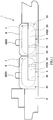
FIG. 2 is a longitudinal sectional view of a part of the ship shown inFIG. 1 . -
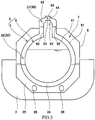
FIG. 3 is a cross-sectional view taken along line III-III ofFIG. 2 . -
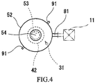
FIG. 4 is a plan view of an outer shell dome. -
FIG. 5 is a sectional view of a part of a ship according to a modification. -
FIG. 6 is a sectional view of a part of a ship according to another modification. -
FIG. 1 shows aship 1 according to one embodiment of the present invention. Theship 1 includes ahull 2 and two double-shell tanks 3 installed in thehull 2. In the present embodiment, the double-shell tanks 3 are cargo tanks for low-temperature fluid transportation. In the present embodiment, the double-shell tanks 3 are arranged in the ship length direction. However, in a case where the ship width is great, the double-shell tanks 3 may be arranged in the ship width direction. The number of the double-shell tanks 3 installed in thehull 2 may be one, or three or more. - The two double-
shell tanks 3 have the same structure. As shown inFIG. 2 andFIG. 3 , each double-shell tank 3 includes aninner shell 4 for storing low-temperature fluid such as liquefied gas, and anouter shell 5 enclosing theinner shell 4. Avacuum space 30 is formed between theinner shell 4 and theouter shell 5. - For example, in the
vacuum space 30, the outer surface of theinner shell 4 may be covered by a vacuum thermal insulator (e.g., a sheet in which radiation shield films and spacers are layered alternately), and a gap where no objects are present may be formed between the vacuum thermal insulator and the inner surface of theouter shell 5. Alternatively, thevacuum space 30 may be filled with pearlite which is a granular thermal insulator. - For example, the liquefied gas is liquefied petroleum gas (LPG, about -45°C), liquefied ethylene gas (LEG, about -100°C), liquefied natural gas (LNG, about -160°C), liquefied oxygen (LO2, about -180°C), liquefied hydrogen (LH2, about -250°C), or liquefied helium (LHe, about -270°C). However, the low-temperature fluid stored in the
inner shell 4 need not be liquid, but may be gas. - To be more specific, the
inner shell 4 includes an inner shellmain part 41 having a horizontally long cylindrical shape, and aninner shell dome 42 protruding upward from the inner shellmain part 41. In the present embodiment, the axial direction of the inner shellmain part 41 is parallel to the ship length direction. In the present embodiment, the axial direction of theinner shell dome 42 is parallel to the vertical direction. Alternatively, the axial direction of theinner shell dome 42 may be slightly inclined relative to the vertical direction. - The
outer shell 5 includes an outer shellmain part 51 and anouter shell dome 52. The outer shellmain part 51 surrounds the inner shellmain part 41 and has a horizontally long cylindrical shape. Theouter shell dome 52 surrounds theinner shell dome 42 and protrudes upward from the outer shellmain part 51. That is, the axial direction of the outer shellmain part 51 is parallel to the ship length direction, similar to the inner shellmain part 41, and the axial direction of theouter shell dome 52 is parallel to the vertical direction, similar to theinner shell dome 42. - However, the inner shell
main part 41 and the outer shellmain part 51 need not have horizontally long cylindrical shapes, but may have vertically long cylindrical shapes. Alternatively, the inner shellmain part 41 and the outer shellmain part 51 may have spherical shapes, cubic shapes, or rectangular parallelepiped shapes. - In the
hull 2, two cargo holds 21 that open upward are formed. The cargo holds 21 are arranged in the ship length direction. The cargo holds 21 are partitioned from each other by abulkhead 22. A lower part of the double-shell tank 3 is inserted in eachcargo hold 21. - In each
cargo hold 21, a pair ofsaddles 25 spaced apart from each other in the ship length direction are provided. Thesaddles 25 support the outer shellmain part 51 of theouter shell 5 of the double-shell tank 3. In addition, a pair ofsupport members 35 supporting the inner shellmain part 41 are provided between theinner shell 4 and theouter shell 5 of the double-shell tank 3. In the present embodiment, thesupport members 35 are provided at the same positions as thesaddles 25. Alternatively, thesupport members 35 may be provided at positions different from thesaddles 25. - A tank cover 6 (corresponding to a ceiling wall in the present invention) is disposed above each double-
shell tank 3. Eachtank cover 6 covers the corresponding double-shell tank 3 from the upper side, and thus a holdingspace 7 to be filled with inert gas is formed between thetank cover 6 and thehull 2. The outer shellmain part 51 of theouter shell 5 described above is positioned under thetank cover 6, and theouter shell dome 52 penetrates thetank cover 6. - As the inert gas to fill the holding
space 7, nitrogen, argon, or the like can be used. The inert gas serves to prevent the holdingspace 7 from having a negative pressure and to prevent condensation on the surface of the double-shell tank 3. In particular, in a case where the low-temperature fluid stored in theinner shell 4 is liquefied hydrogen, the inert gas filling the holdingspace 7 also serves to prevent liquefied oxygen from being generated around the double-shell tank 3. - It should be noted that the holding
space 7 may be filled with gas (e.g., dry air) other than inert gas. Alternatively, the holdingspace 7 may be filled with no such gas, and gas in the holdingspace 7 may be normal air. - The
inner shell dome 42 and theouter shell dome 52 are parts for putting various pipes such as a low-temperature fluid transportation pipe and an electric pipe, and these pipes penetrate theinner shell dome 42 and theouter shell dome 52. At the top portions of theinner shell dome 42 and theouter shell dome 52,manholes manholes covers manholes - A
partition member 33 is disposed between theinner shell dome 42 and theouter shell dome 52. Thepartition member 33 is intended for keeping a major part of thevacuum space 30 vacuum when thecover 54 is detached from theouter shell dome 52 and themanhole 53 is opened. Thepartition member 33 partitions off thevacuum space 30 into anupper region 31 including the internal space of themanhole 53, and alower region 32 enclosing the inner shellmain part 41 overall. - In
FIG. 2 andFIG. 3 , thepartition member 33 is disposed between the peripheral wall portions of theinner shell dome 42 and theouter shell dome 52, and has a flat ring shape. However, the position and the shape of thepartition member 33 may be changed as appropriate. For example, thepartition member 33 may be disposed between the top portions of theinner shell dome 42 and theouter shell dome 52, and have a cylindrical shape. - Further, in the present embodiment, a configuration for additionally evacuating each of the
upper region 31 and thelower region 32 of thevacuum space 30, and a configuration for detecting the degree of vacuum in each of theupper region 31 and thelower region 32, are adopted. - The configurations for additionally evacuating the
upper region 31 and thelower region 32 of thevacuum space 30 include afirst exhaust pipe 81 and asecond exhaust pipe 82, respectively (seeFIG. 2 ). The configurations for detecting the degrees of vacuum in theupper region 31 and thelower region 32 include a plurality of upper vacuum gauges 91 and a plurality oflower vacuum gauges 92, respectively (seeFIG. 2 ). - In the present embodiment, the
first exhaust pipe 81 is disposed above thetank cover 6, and thesecond exhaust pipe 82 is disposed under the double-shell tank 3 in the holdingspace 7. Specifically, thefirst exhaust pipe 81 extends in the horizontal direction from the peripheral wall portion of theouter shell dome 52, and thesecond exhaust pipe 82 extends in the downward direction from the bottom of the outer shellmain part 51 and then extends in the horizontal direction. - To be more specific, one end of the
first exhaust pipe 81 is connected to theouter shell dome 52 at a position above thetank cover 6, so as to communicate with theupper region 31 of thevacuum space 30. Another end of thefirst exhaust pipe 81 is an exhaust port connectable to avacuum pump 11 to be placed on thetank cover 6, and is sealed by a cover in a normal case. At the time of performing an additional evacuating work for theupper region 31, the cover is detached from thefirst exhaust pipe 81 and then thevacuum pump 11 is connected to the other end (exhaust port) of thefirst exhaust pipe 81. - In the present embodiment, the
second exhaust pipe 82 is positioned between the pair ofsaddles 25. One end of thesecond exhaust pipe 82 is connected to the outer shellmain part 51, so as to communicate with thelower region 32 of thevacuum space 30. Another end of thesecond exhaust pipe 82 is an exhaust port connectable to avacuum pump 12 to be placed on the ship bottom, and is sealed by a cover in a normal case. At the time of performing an additional evacuating work for thelower region 32, the cover is detached from thesecond exhaust pipe 82 and then thevacuum pump 12 is connected to the other end (exhaust port) of thesecond exhaust pipe 82. - As shown in
FIG. 3 , eachsaddle 25 is provided withopenings 26 that allow a person to pass therethrough. At the time of performing the additional evacuating work for thelower region 32, the inert gas in the holdingspace 7 is replaced with air, and then thevacuum pump 12 is conveyed through theopening 26 of thesaddle 25 to between the pair ofsaddles 25. - With reference to
FIG. 2 again, the plurality of upper vacuum gauges 91 described above are attached to theouter shell dome 52 at positions above thetank cover 6. The upper vacuum gauges 91 detect the degree of vacuum in theupper region 31 of thevacuum space 30. In the present embodiment, as shown inFIG. 4 , two upper vacuum gauges 91 are provided, and are arranged at equal angular intervals (180-degree intervals in the present embodiment) around theouter shell dome 52. However, the number of the upper vacuum gauges 91 may be three or more. - With reference to
FIG. 2 again, the plurality oflower vacuum gauges 92 are attached to the outer shellmain part 51 on both sides of the pair ofsaddles 25. In other words, the pair ofsaddles 25 are located between the plurality of lower vacuum gauges 92. Thelower vacuum gauges 92 detect the degree of vacuum in thelower region 32 of thevacuum space 30. Although not shown, thelower vacuum gauges 92 are desirably arranged symmetrically with respect to the center of the outer shellmain part 51 in a plan view. - As described above, in the
ship 1 according to the present embodiment, at the time of performing the additional evacuating work for theupper region 31 of thevacuum space 30, it is only necessary to place thevacuum pump 11 on thetank cover 6 and connect thevacuum pump 11 to the exhaust port that is the other end of thefirst exhaust pipe 81. For example, in a state in which theship 1 is moored at a quay or placed in a dock, thevacuum pump 11 is placed on thetank cover 6 by a crane. Thus, it is possible to easily perform the additional evacuating work for theupper region 31 of thevacuum space 30. That is, although the additional evacuating work for thelower region 32 of thevacuum space 30 needs to be performed in the holdingspace 7, the additional evacuating work for theupper region 31 can be easily performed on the upper side of thetank cover 6. In addition, at the time of performing the additional evacuating work for theupper region 31 of thevacuum space 30, it is not necessary to open the holdingspace 7 filled with the inert gas. - Furthermore, in the present embodiment, the upper vacuum gauges 91 are arranged at equal angular intervals around the
outer shell dome 52. Therefore, the degree of vacuum in theupper region 31 of thevacuum space 30 can be monitored not locally but over the entirety. Moreover, since the upper vacuum gauges 91 are positioned above thetank cover 6, the upper vacuum gauges 91 can be easily replaced. - Furthermore, in the present embodiment, the
lower vacuum gauges 92 are positioned on both sides of the pair ofsaddles 25. Therefore, the degree of vacuum in thelower region 32 of thevacuum space 30 can be monitored not locally but over the entirety. Moreover, at the time of replacing thelower vacuum gauges 92, it is not necessary to pass through theopenings 26 of thesaddles 25, and therefore thelower vacuum gauges 92 can be easily replaced. - The present invention is not limited to the above-described embodiment. Various modifications can be made without departing from the scope of the present invention.
- For example, in a case where the volume of the double-
shell tank 3 is small, thepartition member 33 may be omitted so that thevacuum space 30 is a space continuous overall. In this case, thesecond exhaust pipe 82 may also be omitted. - Also in a case where the volume of the double-
shell tank 3 is large, thepartition member 33 may be omitted. For example, as shown inFIG. 5 , while thepartition member 33 is omitted, the height of theouter shell dome 52 may be set to be low and theinner shell dome 42 may penetrate the top portion of theouter shell dome 52. - Furthermore, as shown in
FIG. 5 , one end of theexhaust pipe 81 may be connected to the outer shellmain part 51 and the other end (exhaust port) of theexhaust pipe 81 may be positioned under thetank cover 6. Alternatively, the exhaust port may be positioned on the same plane as thetank cover 6 so as to open on thetank cover 6. However, if theexhaust pipe 81 penetrates thetank cover 6 and the exhaust port is positioned above thetank cover 6, a work for connecting thevacuum pump 11 to the exhaust port can also be performed on the upper side of thetank cover 6. - In addition, the ceiling wall in the present invention need not be the
tank cover 6. For example, as shown inFIG. 6 , in a case where the double-shell tanks 3 are fuel tanks disposed in the hull 2 (inFIG. 6 , these tanks are supported by support members 27), the ceiling wall in the present invention may be anupper deck 28. It should be noted that, inFIG. 6 , the inner shell dome and the outer shell dome are not provided to theinner shell 4 and theouter shell 5. - In the configuration shown in
FIG. 6 , anexhaust pipe 83 extends upward from the top portion of theouter shell 5 of each double-shell tank 3 and penetrates theupper deck 28. One end at the lower side of theexhaust pipe 83 is connected to theouter shell 5, so as to communicate with thevacuum space 30. Another end at the upper side of theexhaust pipe 83 is an exhaust port connectable to avacuum pump 13 to be placed on theupper deck 28. At the time of performing additional evacuation, thevacuum pump 13 is connected to the exhaust port. - In the configuration shown in
FIG. 2 , thesecond exhaust pipe 82 may extend upward from the top portion of the outer shellmain part 51 and penetrate thetank cover 6, and the exhaust port that is the other end of thesecond exhaust pipe 82 and is connectable to thevacuum pump 12 may be positioned above thetank cover 6. In this case, thevacuum pump 12 is also placed on thetank cover 6. -
- 1
- ship
- 2
- hull
- 25
- saddle
- 28
- upper deck (ceiling wall)
- 3
- double-shell tank
- 30
- vacuum space
- 31
- upper region
- 32
- lower region
- 33
- partition member
- 4
- inner shell
- 41
- inner shell main part
- 42
- inner shell dome
- 5
- outer shell
- 51
- outer shell main part
- 52
- outer shell dome
- 6
- tank cover (ceiling wall)
- 7
- holding space
- 81
- first exhaust pipe
- 82
- second exhaust pipe
- 83
- exhaust pipe
- 91
- upper vacuum gauge
- 92
- lower vacuum gauge
Claims (6)
- A ship comprising:a hull;a double-shell tank installed in the hull and including an inner shell and an outer shell with a vacuum space formed therebetween;a ceiling wall covering the double-shell tank from an upper side; andan exhaust pipe including one end connected to the double-shell tank so as to communicate with the vacuum space, and another end that is an exhaust port connectable to a vacuum pump to be placed on the ceiling wall.
- The ship according to claim 1, wherein
the exhaust port is positioned above the ceiling wall. - The ship according to claim 2, whereinthe outer shell includes:an outer shell main part positioned under the ceiling wall; andan outer shell dome protruding upward from the outer shell main part and penetrating the ceiling wall, andthe one end of the exhaust pipe is connected to the outer shell main part or the outer shell dome.
- The ship according to claim 3, whereinthe exhaust pipe is a first exhaust pipe,the inner shell includes:an inner shell main part surrounded by the outer shell main part; andan inner shell dome surrounded by the outer shell dome and protruding upward from the inner shell main part,the ship further comprises:a partition member disposed between the inner shell dome and the outer shell dome, and partitioning off the vacuum space into an upper region and a lower region; anda second exhaust pipe disposed in a holding space formed between the hull and the ceiling wall, the second exhaust pipe including one end connected to the outer shell main part so as to communicate with the lower region of the vacuum space, and another end that is an exhaust port for connecting a vacuum pump, andthe one end of the first exhaust pipe is connected to the outer shell dome at a position above the ceiling wall, so as to communicate with the upper region of the vacuum space.
- The ship according to claim 4, further comprising a plurality of upper vacuum gauges that are attached to the outer shell dome at positions above the ceiling wall and detect a degree of vacuum in the upper region of the vacuum space, wherein
the plurality of upper vacuum gauges are arranged at equal angular intervals around the outer shell dome. - The ship according to claim 4 or 5, whereinthe outer shell main part has a cylindrical shape, an axial direction thereof being parallel to a ship length direction, and is supported by a pair of saddles spaced apart from each other in the ship length direction, andthe ship further comprises a plurality of lower vacuum gauges that are attached to the outer shell main part on both sides of the pair of saddles and detect a degree of vacuum in the lower region of the vacuum space.
Applications Claiming Priority (2)
| Application Number | Priority Date | Filing Date | Title |
|---|---|---|---|
| JP2018247352A JP7273508B2 (en) | 2018-12-28 | 2018-12-28 | vessel |
| PCT/JP2019/050456 WO2020138016A1 (en) | 2018-12-28 | 2019-12-24 | Ship |
Publications (3)
| Publication Number | Publication Date |
|---|---|
| EP3904196A1 true EP3904196A1 (en) | 2021-11-03 |
| EP3904196A4 EP3904196A4 (en) | 2022-11-02 |
| EP3904196B1 EP3904196B1 (en) | 2024-02-28 |
Family
ID=71127689
Family Applications (1)
| Application Number | Title | Priority Date | Filing Date |
|---|---|---|---|
| EP19906121.9A Active EP3904196B1 (en) | 2018-12-28 | 2019-12-24 | Ship |
Country Status (5)
| Country | Link |
|---|---|
| EP (1) | EP3904196B1 (en) |
| JP (1) | JP7273508B2 (en) |
| KR (1) | KR102546082B1 (en) |
| CN (1) | CN113226913B (en) |
| WO (1) | WO2020138016A1 (en) |
Families Citing this family (9)
| Publication number | Priority date | Publication date | Assignee | Title |
|---|---|---|---|---|
| RU2752866C1 (en) * | 2020-09-28 | 2021-08-11 | Дмитрий Владимирович Алексеев | Mobile oven (variants) |
| WO2022144971A1 (en) * | 2020-12-28 | 2022-07-07 | 川崎重工業株式会社 | Multi-shell tank and vessel |
| JP7723493B2 (en) * | 2021-03-31 | 2025-08-14 | 川崎重工業株式会社 | Double-hulled tanks and ships |
| JP7879669B2 (en) * | 2021-03-31 | 2026-06-24 | 川崎重工業株式会社 | Multi-hull tanks and ships |
| JP7807879B2 (en) * | 2021-07-05 | 2026-01-28 | 川崎重工業株式会社 | Ships and liquefied hydrogen tanks |
| JP2024016651A (en) * | 2022-07-26 | 2024-02-07 | 川崎重工業株式会社 | multi-shell structure |
| KR102859276B1 (en) * | 2023-05-12 | 2025-09-17 | 현대자동차주식회사 | Liquid hydrogen container |
| JP2025023672A (en) * | 2023-08-04 | 2025-02-17 | 三菱造船株式会社 | Ships |
| KR102914704B1 (en) * | 2025-09-02 | 2026-01-20 | 한국해양과학기술원 | Active insulated cryogenic fluid storage tank using sacrificial cryogenic fluid system |
Family Cites Families (15)
| Publication number | Priority date | Publication date | Assignee | Title |
|---|---|---|---|---|
| JPS586115B2 (en) * | 1975-09-16 | 1983-02-03 | ブリヂストンエキカガス カブシキガイシヤ | Hakumakushi Kiteion Ekika Gastiyo Zou Sochi |
| JPS5541594A (en) * | 1978-09-20 | 1980-03-24 | Nippon Electric Co | Interface bus system for measuring instrument |
| FR2535831B1 (en) * | 1982-11-05 | 1985-07-12 | Gaz Transport | PROCESS FOR IMPROVING THE THERMAL INSULATION OF A TANK FOR THE STORAGE OF A LIQUEFIED GAS AND CORRESPONDING TANK |
| JPH02249796A (en) * | 1989-03-23 | 1990-10-05 | Ishikawajima Harima Heavy Ind Co Ltd | Liquid carrier ship |
| IT1258958B (en) * | 1992-06-08 | 1996-03-11 | Getters Spa | PROCESS PERFECTED FOR THE CREATION OF THERMALLY INSULATING INSULATION THROUGH VACUUM AND INSULATING MATERIALS |
| US5526678A (en) * | 1994-08-10 | 1996-06-18 | Chicago Bridge & Iron Technical Services Company | Time of flight measurement/rate of rise measurement method for remote leak detection in evacuated spaces |
| JP2002147694A (en) * | 2000-11-16 | 2002-05-22 | Mitsubishi Heavy Ind Ltd | Cryogenic fluid storage container |
| JP5173917B2 (en) * | 2009-04-15 | 2013-04-03 | 三菱重工業株式会社 | LNG carrier |
| JP5670225B2 (en) * | 2011-03-03 | 2015-02-18 | 川崎重工業株式会社 | Tank dome flange structure |
| WO2012131788A1 (en) * | 2011-03-31 | 2012-10-04 | シチズンファインテックミヨタ株式会社 | Cylinder internal-pressure sensor for engine |
| JP2014118206A (en) * | 2012-12-19 | 2014-06-30 | Kawasaki Heavy Ind Ltd | Liquefied gas transport container |
| JP6134211B2 (en) * | 2013-06-19 | 2017-05-24 | 川崎重工業株式会社 | Double shell tank and liquefied gas carrier |
| KR101865210B1 (en) * | 2013-06-21 | 2018-06-07 | 카와사키 주코교 카부시키 카이샤 | Liquefied gas-storing tank and liquefied gas transport vessel |
| KR20160036837A (en) * | 2014-09-26 | 2016-04-05 | 대우조선해양 주식회사 | Boil-off Rate Reduction Method for Liquified Natural Gas Storage Tank |
| WO2017138044A1 (en) * | 2016-02-12 | 2017-08-17 | 川崎重工業株式会社 | Double-shell tank for ship |
-
2018
- 2018-12-28 JP JP2018247352A patent/JP7273508B2/en active Active
-
2019
- 2019-12-24 EP EP19906121.9A patent/EP3904196B1/en active Active
- 2019-12-24 CN CN201980086041.8A patent/CN113226913B/en active Active
- 2019-12-24 KR KR1020217023139A patent/KR102546082B1/en active Active
- 2019-12-24 WO PCT/JP2019/050456 patent/WO2020138016A1/en not_active Ceased
Also Published As
| Publication number | Publication date |
|---|---|
| KR102546082B1 (en) | 2023-06-21 |
| EP3904196A4 (en) | 2022-11-02 |
| JP2020104787A (en) | 2020-07-09 |
| CN113226913B (en) | 2024-10-01 |
| KR20210105967A (en) | 2021-08-27 |
| EP3904196B1 (en) | 2024-02-28 |
| JP7273508B2 (en) | 2023-05-15 |
| WO2020138016A1 (en) | 2020-07-02 |
| CN113226913A (en) | 2021-08-06 |
Similar Documents
| Publication | Publication Date | Title |
|---|---|---|
| EP3904196B1 (en) | Ship | |
| CN105264279B (en) | Double-shelled storage tank and liquid gas carry vessel | |
| CN111727343A (en) | Facilities for storing and transporting liquefied gases | |
| KR102967996B1 (en) | Insulated sealed tank | |
| CN102947638B (en) | Support of tanks in vessels | |
| EP3760530A1 (en) | Ship | |
| KR20160009680A (en) | Liquefied gas-storing tank and liquefied gas transport vessel | |
| KR102782464B1 (en) | shipping | |
| KR20210071318A (en) | Pump Tower of Liquefied Gas Storage Tank | |
| KR101419821B1 (en) | Dual structure of storing container for liquefied natural gas | |
| KR20200102383A (en) | Sealed and thermally insulating tank | |
| EP3760910A1 (en) | Double-shell tank and liquefied gas carrier | |
| CN116353772A (en) | A cryogenic storage liquid cargo tank structure and ship | |
| KR20210070756A (en) | Pump Tower Supporting Structure of Liquefied Gas Storage Tank | |
| JP2023090674A (en) | Liquefied gas storage facility with tank and dome structure | |
| KR20210071317A (en) | Pump Tower of Liquefied Gas Storage Tank including Spraying Pipe | |
| KR20140004166U (en) | Collecting Device Of Leak For Independent Type Cargo Tank | |
| KR20220062405A (en) | airtight insulated tank | |
| KR101337272B1 (en) | Topside load support structure of floating ocean construct | |
| WO2022039256A1 (en) | Liquefied gas carrying ship | |
| KR20120031045A (en) | Topside load support structure of floating ocean construct | |
| KR20140017165A (en) | Unloading system for lng carrier | |
| KR102751080B1 (en) | apparatus of manufacturing liquefied gas storage tank | |
| KR20170034548A (en) | Insulation Box Of Cargo Tank And Manufacturing Method Of The Same | |
| KR101498243B1 (en) | Floating ocean construct |
Legal Events
| Date | Code | Title | Description |
|---|---|---|---|
| STAA | Information on the status of an ep patent application or granted ep patent |
Free format text: STATUS: THE INTERNATIONAL PUBLICATION HAS BEEN MADE |
|
| PUAI | Public reference made under article 153(3) epc to a published international application that has entered the european phase |
Free format text: ORIGINAL CODE: 0009012 |
|
| STAA | Information on the status of an ep patent application or granted ep patent |
Free format text: STATUS: REQUEST FOR EXAMINATION WAS MADE |
|
| 17P | Request for examination filed |
Effective date: 20210727 |
|
| AK | Designated contracting states |
Kind code of ref document: A1 Designated state(s): AL AT BE BG CH CY CZ DE DK EE ES FI FR GB GR HR HU IE IS IT LI LT LU LV MC MK MT NL NO PL PT RO RS SE SI SK SM TR |
|
| DAV | Request for validation of the european patent (deleted) | ||
| DAX | Request for extension of the european patent (deleted) | ||
| A4 | Supplementary search report drawn up and despatched |
Effective date: 20221004 |
|
| RIC1 | Information provided on ipc code assigned before grant |
Ipc: B65D 90/02 20190101ALI20220928BHEP Ipc: F17C 3/08 20060101ALI20220928BHEP Ipc: B63B 25/16 20060101AFI20220928BHEP |
|
| STAA | Information on the status of an ep patent application or granted ep patent |
Free format text: STATUS: EXAMINATION IS IN PROGRESS |
|
| 17Q | First examination report despatched |
Effective date: 20230526 |
|
| GRAP | Despatch of communication of intention to grant a patent |
Free format text: ORIGINAL CODE: EPIDOSNIGR1 |
|
| STAA | Information on the status of an ep patent application or granted ep patent |
Free format text: STATUS: GRANT OF PATENT IS INTENDED |
|
| INTG | Intention to grant announced |
Effective date: 20231123 |
|
| GRAS | Grant fee paid |
Free format text: ORIGINAL CODE: EPIDOSNIGR3 |
|
| GRAA | (expected) grant |
Free format text: ORIGINAL CODE: 0009210 |
|
| STAA | Information on the status of an ep patent application or granted ep patent |
Free format text: STATUS: THE PATENT HAS BEEN GRANTED |
|
| AK | Designated contracting states |
Kind code of ref document: B1 Designated state(s): AL AT BE BG CH CY CZ DE DK EE ES FI FR GB GR HR HU IE IS IT LI LT LU LV MC MK MT NL NO PL PT RO RS SE SI SK SM TR |
|
| REG | Reference to a national code |
Ref country code: GB Ref legal event code: FG4D |
|
| REG | Reference to a national code |
Ref country code: CH Ref legal event code: EP |
|
| REG | Reference to a national code |
Ref country code: DE Ref legal event code: R096 Ref document number: 602019047551 Country of ref document: DE |
|
| REG | Reference to a national code |
Ref country code: IE Ref legal event code: FG4D |
|
| REG | Reference to a national code |
Ref country code: LT Ref legal event code: MG9D |
|
| PG25 | Lapsed in a contracting state [announced via postgrant information from national office to epo] |
Ref country code: IS Free format text: LAPSE BECAUSE OF FAILURE TO SUBMIT A TRANSLATION OF THE DESCRIPTION OR TO PAY THE FEE WITHIN THE PRESCRIBED TIME-LIMIT Effective date: 20240628 |
|
| REG | Reference to a national code |
Ref country code: NL Ref legal event code: MP Effective date: 20240228 |
|
| PG25 | Lapsed in a contracting state [announced via postgrant information from national office to epo] |
Ref country code: LT Free format text: LAPSE BECAUSE OF FAILURE TO SUBMIT A TRANSLATION OF THE DESCRIPTION OR TO PAY THE FEE WITHIN THE PRESCRIBED TIME-LIMIT Effective date: 20240228 |
|
| PG25 | Lapsed in a contracting state [announced via postgrant information from national office to epo] |
Ref country code: GR Free format text: LAPSE BECAUSE OF FAILURE TO SUBMIT A TRANSLATION OF THE DESCRIPTION OR TO PAY THE FEE WITHIN THE PRESCRIBED TIME-LIMIT Effective date: 20240529 |
|
| PG25 | Lapsed in a contracting state [announced via postgrant information from national office to epo] |
Ref country code: RS Free format text: LAPSE BECAUSE OF FAILURE TO SUBMIT A TRANSLATION OF THE DESCRIPTION OR TO PAY THE FEE WITHIN THE PRESCRIBED TIME-LIMIT Effective date: 20240528 Ref country code: HR Free format text: LAPSE BECAUSE OF FAILURE TO SUBMIT A TRANSLATION OF THE DESCRIPTION OR TO PAY THE FEE WITHIN THE PRESCRIBED TIME-LIMIT Effective date: 20240228 Ref country code: NL Free format text: LAPSE BECAUSE OF FAILURE TO SUBMIT A TRANSLATION OF THE DESCRIPTION OR TO PAY THE FEE WITHIN THE PRESCRIBED TIME-LIMIT Effective date: 20240228 |
|
| PG25 | Lapsed in a contracting state [announced via postgrant information from national office to epo] |
Ref country code: ES Free format text: LAPSE BECAUSE OF FAILURE TO SUBMIT A TRANSLATION OF THE DESCRIPTION OR TO PAY THE FEE WITHIN THE PRESCRIBED TIME-LIMIT Effective date: 20240228 |
|
| PG25 | Lapsed in a contracting state [announced via postgrant information from national office to epo] |
Ref country code: RS Free format text: LAPSE BECAUSE OF FAILURE TO SUBMIT A TRANSLATION OF THE DESCRIPTION OR TO PAY THE FEE WITHIN THE PRESCRIBED TIME-LIMIT Effective date: 20240528 Ref country code: NL Free format text: LAPSE BECAUSE OF FAILURE TO SUBMIT A TRANSLATION OF THE DESCRIPTION OR TO PAY THE FEE WITHIN THE PRESCRIBED TIME-LIMIT Effective date: 20240228 Ref country code: LT Free format text: LAPSE BECAUSE OF FAILURE TO SUBMIT A TRANSLATION OF THE DESCRIPTION OR TO PAY THE FEE WITHIN THE PRESCRIBED TIME-LIMIT Effective date: 20240228 Ref country code: IS Free format text: LAPSE BECAUSE OF FAILURE TO SUBMIT A TRANSLATION OF THE DESCRIPTION OR TO PAY THE FEE WITHIN THE PRESCRIBED TIME-LIMIT Effective date: 20240628 Ref country code: HR Free format text: LAPSE BECAUSE OF FAILURE TO SUBMIT A TRANSLATION OF THE DESCRIPTION OR TO PAY THE FEE WITHIN THE PRESCRIBED TIME-LIMIT Effective date: 20240228 Ref country code: GR Free format text: LAPSE BECAUSE OF FAILURE TO SUBMIT A TRANSLATION OF THE DESCRIPTION OR TO PAY THE FEE WITHIN THE PRESCRIBED TIME-LIMIT Effective date: 20240529 Ref country code: FI Free format text: LAPSE BECAUSE OF FAILURE TO SUBMIT A TRANSLATION OF THE DESCRIPTION OR TO PAY THE FEE WITHIN THE PRESCRIBED TIME-LIMIT Effective date: 20240228 Ref country code: ES Free format text: LAPSE BECAUSE OF FAILURE TO SUBMIT A TRANSLATION OF THE DESCRIPTION OR TO PAY THE FEE WITHIN THE PRESCRIBED TIME-LIMIT Effective date: 20240228 Ref country code: BG Free format text: LAPSE BECAUSE OF FAILURE TO SUBMIT A TRANSLATION OF THE DESCRIPTION OR TO PAY THE FEE WITHIN THE PRESCRIBED TIME-LIMIT Effective date: 20240228 |
|
| PG25 | Lapsed in a contracting state [announced via postgrant information from national office to epo] |
Ref country code: PT Free format text: LAPSE BECAUSE OF FAILURE TO SUBMIT A TRANSLATION OF THE DESCRIPTION OR TO PAY THE FEE WITHIN THE PRESCRIBED TIME-LIMIT Effective date: 20240628 Ref country code: PL Free format text: LAPSE BECAUSE OF FAILURE TO SUBMIT A TRANSLATION OF THE DESCRIPTION OR TO PAY THE FEE WITHIN THE PRESCRIBED TIME-LIMIT Effective date: 20240228 |
|
| REG | Reference to a national code |
Ref country code: AT Ref legal event code: MK05 Ref document number: 1661025 Country of ref document: AT Kind code of ref document: T Effective date: 20240228 |
|
| PG25 | Lapsed in a contracting state [announced via postgrant information from national office to epo] |
Ref country code: SE Free format text: LAPSE BECAUSE OF FAILURE TO SUBMIT A TRANSLATION OF THE DESCRIPTION OR TO PAY THE FEE WITHIN THE PRESCRIBED TIME-LIMIT Effective date: 20240228 Ref country code: PT Free format text: LAPSE BECAUSE OF FAILURE TO SUBMIT A TRANSLATION OF THE DESCRIPTION OR TO PAY THE FEE WITHIN THE PRESCRIBED TIME-LIMIT Effective date: 20240628 Ref country code: PL Free format text: LAPSE BECAUSE OF FAILURE TO SUBMIT A TRANSLATION OF THE DESCRIPTION OR TO PAY THE FEE WITHIN THE PRESCRIBED TIME-LIMIT Effective date: 20240228 Ref country code: LV Free format text: LAPSE BECAUSE OF FAILURE TO SUBMIT A TRANSLATION OF THE DESCRIPTION OR TO PAY THE FEE WITHIN THE PRESCRIBED TIME-LIMIT Effective date: 20240228 |
|
| PG25 | Lapsed in a contracting state [announced via postgrant information from national office to epo] |
Ref country code: DK Free format text: LAPSE BECAUSE OF FAILURE TO SUBMIT A TRANSLATION OF THE DESCRIPTION OR TO PAY THE FEE WITHIN THE PRESCRIBED TIME-LIMIT Effective date: 20240228 |
|
| PG25 | Lapsed in a contracting state [announced via postgrant information from national office to epo] |
Ref country code: SM Free format text: LAPSE BECAUSE OF FAILURE TO SUBMIT A TRANSLATION OF THE DESCRIPTION OR TO PAY THE FEE WITHIN THE PRESCRIBED TIME-LIMIT Effective date: 20240228 |
|
| PG25 | Lapsed in a contracting state [announced via postgrant information from national office to epo] |
Ref country code: CZ Free format text: LAPSE BECAUSE OF FAILURE TO SUBMIT A TRANSLATION OF THE DESCRIPTION OR TO PAY THE FEE WITHIN THE PRESCRIBED TIME-LIMIT Effective date: 20240228 Ref country code: EE Free format text: LAPSE BECAUSE OF FAILURE TO SUBMIT A TRANSLATION OF THE DESCRIPTION OR TO PAY THE FEE WITHIN THE PRESCRIBED TIME-LIMIT Effective date: 20240228 |
|
| PG25 | Lapsed in a contracting state [announced via postgrant information from national office to epo] |
Ref country code: AT Free format text: LAPSE BECAUSE OF FAILURE TO SUBMIT A TRANSLATION OF THE DESCRIPTION OR TO PAY THE FEE WITHIN THE PRESCRIBED TIME-LIMIT Effective date: 20240228 |
|
| PG25 | Lapsed in a contracting state [announced via postgrant information from national office to epo] |
Ref country code: SK Free format text: LAPSE BECAUSE OF FAILURE TO SUBMIT A TRANSLATION OF THE DESCRIPTION OR TO PAY THE FEE WITHIN THE PRESCRIBED TIME-LIMIT Effective date: 20240228 |
|
| PG25 | Lapsed in a contracting state [announced via postgrant information from national office to epo] |
Ref country code: SM Free format text: LAPSE BECAUSE OF FAILURE TO SUBMIT A TRANSLATION OF THE DESCRIPTION OR TO PAY THE FEE WITHIN THE PRESCRIBED TIME-LIMIT Effective date: 20240228 Ref country code: SK Free format text: LAPSE BECAUSE OF FAILURE TO SUBMIT A TRANSLATION OF THE DESCRIPTION OR TO PAY THE FEE WITHIN THE PRESCRIBED TIME-LIMIT Effective date: 20240228 Ref country code: RO Free format text: LAPSE BECAUSE OF FAILURE TO SUBMIT A TRANSLATION OF THE DESCRIPTION OR TO PAY THE FEE WITHIN THE PRESCRIBED TIME-LIMIT Effective date: 20240228 Ref country code: EE Free format text: LAPSE BECAUSE OF FAILURE TO SUBMIT A TRANSLATION OF THE DESCRIPTION OR TO PAY THE FEE WITHIN THE PRESCRIBED TIME-LIMIT Effective date: 20240228 Ref country code: DK Free format text: LAPSE BECAUSE OF FAILURE TO SUBMIT A TRANSLATION OF THE DESCRIPTION OR TO PAY THE FEE WITHIN THE PRESCRIBED TIME-LIMIT Effective date: 20240228 Ref country code: CZ Free format text: LAPSE BECAUSE OF FAILURE TO SUBMIT A TRANSLATION OF THE DESCRIPTION OR TO PAY THE FEE WITHIN THE PRESCRIBED TIME-LIMIT Effective date: 20240228 Ref country code: AT Free format text: LAPSE BECAUSE OF FAILURE TO SUBMIT A TRANSLATION OF THE DESCRIPTION OR TO PAY THE FEE WITHIN THE PRESCRIBED TIME-LIMIT Effective date: 20240228 |
|
| REG | Reference to a national code |
Ref country code: DE Ref legal event code: R097 Ref document number: 602019047551 Country of ref document: DE |
|
| PG25 | Lapsed in a contracting state [announced via postgrant information from national office to epo] |
Ref country code: IT Free format text: LAPSE BECAUSE OF FAILURE TO SUBMIT A TRANSLATION OF THE DESCRIPTION OR TO PAY THE FEE WITHIN THE PRESCRIBED TIME-LIMIT Effective date: 20240228 |
|
| PG25 | Lapsed in a contracting state [announced via postgrant information from national office to epo] |
Ref country code: IT Free format text: LAPSE BECAUSE OF FAILURE TO SUBMIT A TRANSLATION OF THE DESCRIPTION OR TO PAY THE FEE WITHIN THE PRESCRIBED TIME-LIMIT Effective date: 20240228 |
|
| PLBE | No opposition filed within time limit |
Free format text: ORIGINAL CODE: 0009261 |
|
| STAA | Information on the status of an ep patent application or granted ep patent |
Free format text: STATUS: NO OPPOSITION FILED WITHIN TIME LIMIT |
|
| 26N | No opposition filed |
Effective date: 20241129 |
|
| PG25 | Lapsed in a contracting state [announced via postgrant information from national office to epo] |
Ref country code: SI Free format text: LAPSE BECAUSE OF FAILURE TO SUBMIT A TRANSLATION OF THE DESCRIPTION OR TO PAY THE FEE WITHIN THE PRESCRIBED TIME-LIMIT Effective date: 20240228 |
|
| REG | Reference to a national code |
Ref country code: DE Ref legal event code: R119 Ref document number: 602019047551 Country of ref document: DE |
|
| PG25 | Lapsed in a contracting state [announced via postgrant information from national office to epo] |
Ref country code: MC Free format text: LAPSE BECAUSE OF FAILURE TO SUBMIT A TRANSLATION OF THE DESCRIPTION OR TO PAY THE FEE WITHIN THE PRESCRIBED TIME-LIMIT Effective date: 20240228 |
|
| REG | Reference to a national code |
Ref country code: CH Ref legal event code: PL |
|
| PG25 | Lapsed in a contracting state [announced via postgrant information from national office to epo] |
Ref country code: LU Free format text: LAPSE BECAUSE OF NON-PAYMENT OF DUE FEES Effective date: 20241224 |
|
| GBPC | Gb: european patent ceased through non-payment of renewal fee |
Effective date: 20241224 |
|
| REG | Reference to a national code |
Ref country code: BE Ref legal event code: MM Effective date: 20241231 |
|
| PG25 | Lapsed in a contracting state [announced via postgrant information from national office to epo] |
Ref country code: DE Free format text: LAPSE BECAUSE OF NON-PAYMENT OF DUE FEES Effective date: 20250701 |
|
| PG25 | Lapsed in a contracting state [announced via postgrant information from national office to epo] |
Ref country code: GB Free format text: LAPSE BECAUSE OF NON-PAYMENT OF DUE FEES Effective date: 20241224 Ref country code: BE Free format text: LAPSE BECAUSE OF NON-PAYMENT OF DUE FEES Effective date: 20241231 |
|
| PG25 | Lapsed in a contracting state [announced via postgrant information from national office to epo] |
Ref country code: FR Free format text: LAPSE BECAUSE OF NON-PAYMENT OF DUE FEES Effective date: 20241231 |
|
| PG25 | Lapsed in a contracting state [announced via postgrant information from national office to epo] |
Ref country code: CH Free format text: LAPSE BECAUSE OF NON-PAYMENT OF DUE FEES Effective date: 20241231 |
|
| PG25 | Lapsed in a contracting state [announced via postgrant information from national office to epo] |
Ref country code: IE Free format text: LAPSE BECAUSE OF NON-PAYMENT OF DUE FEES Effective date: 20241224 |
|
| PGFP | Annual fee paid to national office [announced via postgrant information from national office to epo] |
Ref country code: NO Payment date: 20251210 Year of fee payment: 7 |
|
| PG25 | Lapsed in a contracting state [announced via postgrant information from national office to epo] |
Ref country code: CY Free format text: LAPSE BECAUSE OF FAILURE TO SUBMIT A TRANSLATION OF THE DESCRIPTION OR TO PAY THE FEE WITHIN THE PRESCRIBED TIME-LIMIT Effective date: 20240228 |
|
| PG25 | Lapsed in a contracting state [announced via postgrant information from national office to epo] |
Ref country code: TR Free format text: LAPSE BECAUSE OF FAILURE TO SUBMIT A TRANSLATION OF THE DESCRIPTION OR TO PAY THE FEE WITHIN THE PRESCRIBED TIME-LIMIT Effective date: 20240228 |
|
| PG25 | Lapsed in a contracting state [announced via postgrant information from national office to epo] |
Ref country code: HU Free format text: LAPSE BECAUSE OF FAILURE TO SUBMIT A TRANSLATION OF THE DESCRIPTION OR TO PAY THE FEE WITHIN THE PRESCRIBED TIME-LIMIT; INVALID AB INITIO Effective date: 20191224 |