EP3903899A1 - Degassing system, method for degassing liquids, degassing unit, degassing module, and degassing-system manufacturing method and method of production from natural resources - Google Patents
Degassing system, method for degassing liquids, degassing unit, degassing module, and degassing-system manufacturing method and method of production from natural resources Download PDFInfo
- Publication number
- EP3903899A1 EP3903899A1 EP19901994.4A EP19901994A EP3903899A1 EP 3903899 A1 EP3903899 A1 EP 3903899A1 EP 19901994 A EP19901994 A EP 19901994A EP 3903899 A1 EP3903899 A1 EP 3903899A1
- Authority
- EP
- European Patent Office
- Prior art keywords
- degasification
- liquid
- unit
- units
- hollow fiber
- Prior art date
- Legal status (The legal status is an assumption and is not a legal conclusion. Google has not performed a legal analysis and makes no representation as to the accuracy of the status listed.)
- Granted
Links
Images







Classifications
-
- B—PERFORMING OPERATIONS; TRANSPORTING
- B01—PHYSICAL OR CHEMICAL PROCESSES OR APPARATUS IN GENERAL
- B01D—SEPARATION
- B01D19/00—Degasification of liquids
- B01D19/0031—Degasification of liquids by filtration
-
- B—PERFORMING OPERATIONS; TRANSPORTING
- B01—PHYSICAL OR CHEMICAL PROCESSES OR APPARATUS IN GENERAL
- B01D—SEPARATION
- B01D63/00—Apparatus in general for separation processes using semi-permeable membranes
- B01D63/02—Hollow fibre modules
- B01D63/021—Manufacturing thereof
- B01D63/0233—Manufacturing thereof forming the bundle
-
- B—PERFORMING OPERATIONS; TRANSPORTING
- B01—PHYSICAL OR CHEMICAL PROCESSES OR APPARATUS IN GENERAL
- B01D—SEPARATION
- B01D63/00—Apparatus in general for separation processes using semi-permeable membranes
- B01D63/02—Hollow fibre modules
- B01D63/04—Hollow fibre modules comprising multiple hollow fibre assemblies
- B01D63/043—Hollow fibre modules comprising multiple hollow fibre assemblies with separate tube sheets
-
- B—PERFORMING OPERATIONS; TRANSPORTING
- B01—PHYSICAL OR CHEMICAL PROCESSES OR APPARATUS IN GENERAL
- B01D—SEPARATION
- B01D65/00—Accessories or auxiliary operations, in general, for separation processes or apparatus using semi-permeable membranes
- B01D65/003—Membrane bonding or sealing
-
- E—FIXED CONSTRUCTIONS
- E21—EARTH OR ROCK DRILLING; MINING
- E21B—EARTH OR ROCK DRILLING; OBTAINING OIL, GAS, WATER, SOLUBLE OR MELTABLE MATERIALS OR A SLURRY OF MINERALS FROM WELLS
- E21B43/00—Methods or apparatus for obtaining oil, gas, water, soluble or meltable materials or a slurry of minerals from wells
- E21B43/34—Arrangements for separating materials produced by the well
- E21B43/40—Separation associated with re-injection of separated materials
-
- B—PERFORMING OPERATIONS; TRANSPORTING
- B01—PHYSICAL OR CHEMICAL PROCESSES OR APPARATUS IN GENERAL
- B01D—SEPARATION
- B01D2313/00—Details relating to membrane modules or apparatus
- B01D2313/10—Specific supply elements
-
- B—PERFORMING OPERATIONS; TRANSPORTING
- B01—PHYSICAL OR CHEMICAL PROCESSES OR APPARATUS IN GENERAL
- B01D—SEPARATION
- B01D2313/00—Details relating to membrane modules or apparatus
- B01D2313/12—Specific discharge elements
Definitions
- An aspect of the present invention relates to a degasification system in which a plurality of degasification units are housed in parallel in a housing, a liquid degasification method using the degasification system, a degasification unit used in the degasification system, a degasification module used in the degasification system, a method for manufacturing the degasification system, and a method for producing natural resources.
- a degasification unit that degasifies a liquid using hollow fiber membranes is known. Further, a degasification system in which a plurality of degasification units are housed in a housing to cope with an increase in size or flow rate is also known (see Patent Literature 1, for example).
- Patent Literature 1 Japanese Patent No. 4593719
- an object of the aspect of the present invention is to provide a degasification system capable of reducing deviation in the flow rate of a liquid flowing through a plurality of degasification units, a liquid degasification method using the degasification system, a degasification unit used in the degasification system, a degasification module used in the degasification system, a method for manufacturing the degasification system, and a method for producing natural resources.
- a degasification system includes a plurality of degasification units configured to degasify a liquid; and a cylindrical housing configured to house the plurality of degasification units in parallel, wherein each of the plurality of degasification units includes a hollow fiber membrane bundle in which a plurality of hollow fiber membranes are bundled in a cylindrical shape and a cylinder in which the hollow fiber membrane bundle is housed, wherein the housing has an inlet through which the liquid is supplied from outside, an outlet through which the liquid is discharged to the outside, and a sealing portion which partitions an internal space of the housing into an upstream side region on the inlet side and a downstream side region on the outlet side via the plurality of degasification units, and wherein the plurality of degasification units are configured such that pressure losses of the liquid differ depending on a distance from a central axis of the housing.
- the plurality of degasification units are housed in parallel in the cylindrical housing.
- the pressure losses of the liquid flowing through the plurality of degasification units are the same, the flow rates of the liquid flowing through the degasification units differ depending on the distance from the central axis of the housing.
- the plurality of degasification units are configured such that the pressure losses of the liquid differ depending on the distance from the central axis of the housing. This difference in the pressure loss acts to offset the above difference in the flow rate. As a result, it is possible to reduce the deviation in the flow rate of the liquid flowing through the plurality of degasification units. As a result, for example, the degasification performance of the degasification system in its entirety can be improved.
- the degasification system may further include a suction pipe communicating with an inside of the hollow fiber membranes and penetrating the housing to suction the inside of the hollow fiber membranes.
- a suction pipe communicating with an inside of the hollow fiber membranes and penetrating the housing to suction the inside of the hollow fiber membranes.
- the degasification unit that overlaps the inlet when seen in a direction along the central axis may be configured such that the pressure loss of the liquid therein is larger than that in the degasification unit that does not overlap the inlet when seen in a direction along the central axis. Since the degasification unit that overlaps the inlet when seen in a direction along the central axis receives a stronger supply pressure of the liquid from the inlet than that in the degasification unit that does not overlap the inlet when seen in a direction along the central axis, the liquid easily flows in the degasification unit that overlaps the inlet when seen in a direction along the central axis.
- the degasification unit that overlaps the inlet when seen in a direction along the central axis is configured such that the pressure loss of the liquid therein is larger than that in the degasification unit that does not overlap the inlet when seen in a direction along the central axis, this difference in the pressure loss acts to offset the difference in the supply pressure of the liquid. As a result, it is possible to reduce the deviation in the flow rate of the liquid flowing through these degasification units.
- the flow rate of the liquid flowing through the degasification unit tends to decrease as the degasification unit becomes further away from the central axis of the housing.
- the above tendency is reversed in an outer region from the inner peripheral surface of the housing to a position corresponding to 0.7 times the outer diameter of the degasification unit toward the central axis side. That is, it was found that in the outer region, the flow rate of the liquid flowing through the degasification unit tends to increase as the degasification unit becomes further away from the central axis of the housing. It is assumed that this is because, in the outer region, the liquid flowing in the housing is pushed back against the inner peripheral surface of the housing, and thus the flow rate of the liquid flowing through the degasification unit increases.
- the plurality of degasification units may have an inner degasification unit and an outer degasification unit which is farther from the central axis than the inner degasification unit, and the inner degasification unit may be configured such that the pressure loss of the liquid therein is larger than that in the outer degasification unit.
- the flow rate of the liquid flowing through the degasification unit tends to decrease as the degasification unit becomes further away from the central axis of the housing.
- the inner degasification unit is configured such that the pressure loss of the liquid therein is larger than that in the outer degasification unit, this difference in the pressure loss acts to offset the above difference in the flow rate. As a result, it is possible to reduce the deviation in the flow rate of the liquid flowing through the inner degasification unit and the outer degasification unit.
- the plurality of degasification units may be configured such that the pressure loss of the liquid increases as the degasification unit becomes further away from the central axis.
- the plurality of degasification units are configured such that the pressure loss of the liquid increases as the degasification unit becomes further away from the central axis, and thus it is possible to appropriately reduce the deviation in the flow rate of the liquid flowing through the plurality of degasification units.
- the degasification units disposed in the inner region may be configured such that the pressure loss of the liquid increases as the degasification unit becomes further away from the central axis.
- the degasification units disposed in the inner region are configured such that the pressure loss of the liquid increases as the degasification unit becomes further away from the central axis, and thus it is possible to appropriately reduce the deviation in the flow rate of the liquid flowing through the degasification units in the inner region.
- the degasification unit disposed in the outer region may be configured such that the pressure loss of the liquid therein is larger than that in the degasification unit closest to the outer region among the degasification units disposed in the inner region.
- the degasification unit disposed in the outer region is configured such that the pressure loss of the liquid therein is larger than that in the degasification unit closest to the outer region among the degasification units disposed in the inner region, it is possible to appropriately reduce the deviation in the flow rate of the liquid even between this degasification unit disposed in the inner region and the degasification unit disposed in the outer region.
- each of the plurality of the degasification modules may include a hollow fiber membrane bundle having a plurality of hollow fiber membranes arranged around a liquid supply path through which a liquid is supplied and a cylinder which houses the hollow fiber membrane bundle and in which discharge ports for discharging the liquid are formed, and the degasification unit may have a connection supply pipe which connects the liquid supply paths of the plurality of degasification modules in series and in which openings through which the liquid passes are formed at positions corresponding to the plurality of degasification modules such that the liquid is supplied to the hollow fiber membrane bundles of the plurality of degasification modules in parallel.
- a liquid degasification method in any one of the above degasification systems includes degasifying a liquid by supplying the liquid from the inlet to the plurality of degasification units and depressurizing an inside of the plurality of hollow fiber membranes of each of the plurality of degasification units.
- a degasification unit used in any one of the above degasification systems includes a hollow fiber membrane bundle in which a plurality of hollow fiber membranes are bundled in a cylindrical shape; and a cylinder in which the hollow fiber membrane bundle is housed.
- a degasification module according to an aspect of the present invention used in the above degasification system includes a hollow fiber membrane bundle having a plurality of hollow fiber membranes arranged around a liquid supply path through which a liquid is supplied; and a cylinder which houses the hollow fiber membrane bundle and in which discharge ports for discharging the liquid are formed.
- a method for manufacturing a degasification system includes preparing a plurality of degasification units, a housing which houses the plurality of degasification units and has an inlet through which a liquid is supplied from outside and an outlet through which the liquid is discharged to the outside, and a suction pipe; fixing the plurality of the degasification units to the housing with a sealing portion which partitions an internal space of the housing into an upstream side region on the inlet side and a downstream side region on the outlet side via the plurality of degasification units; and making pressure losses of the liquid of the plurality of degasification units different depending on a distance from a central axis of the housing.
- the method for manufacturing a degasification system may further include preparing a plurality of degasification modules each having a hollow fiber membrane bundle having a plurality of hollow fiber membranes arranged around a liquid supply path through which a liquid is supplied and a cylinder which houses the hollow fiber membrane bundle and in which discharge ports for discharging the liquid are formed, and a connection supply pipe in which a plurality of openings through which the liquid passes are formed; and inserting the connection supply pipe into the liquid supply paths of the plurality of degasification modules to connect the liquid supply paths of the plurality of degasification modules in series by the connection supply pipe and disposing the plurality of openings at positions corresponding to the plurality of degasification modules such that the liquid is supplied to the hollow fiber membrane bundles of the plurality of degasification modules in parallel, to manufacture the degasification unit.
- a method for producing natural resources according to an aspect of the present invention in any one of the degasification systems includes a degasification step of degasifying a liquid by supplying the liquid from the inlet to the plurality of degasification units and depressurizing an inside of the plurality of hollow fiber membranes of each of the plurality of degasification units; and a press-in step of pressing-in the liquid degasified in the degasification step into a natural resource mining site.
- a degasification system capable of reducing deviation in the flow rate of a liquid flowing through a plurality of degasification units is provided.
- the degasification system of the present embodiment is a system for degasifying a liquid.
- the liquid to be degasified by the degasification system water is exemplified.
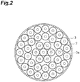
- the degasification system 1 of the present embodiment includes a plurality of degasification units 2, a housing 3 which houses the degasification unit 2, and a suction pipe 4 (see FIGS. 3 to 5 ).
- the degasification unit 2 may be constituted by a plurality of degasification modules 5 being connected to each other as in a degasification unit 2A shown in FIG. 3 and may be constituted by one degasification module 5 as in a degasification unit 2B shown in FIG. 4 .
- the degasification unit 2A shown in FIG. 3 and the degasification unit 2B shown in FIG. 4 each show an example of the degasification unit 2. Further, in FIGS. 3 and 4 , to make the drawings easier to see, only one of the plurality of degasification units 2 is illustrated, and the remaining degasification units 2 are omitted.
- the degasification module 5 includes, for example, a module inner pipe 11, a hollow fiber membrane bundle 12, and a module container (a cylinder) 13.
- the module inner pipe 11 is a pipe on an inner peripheral side of which a liquid supply path 10 to which a liquid such as water is supplied is formed.
- the module inner pipe 11 is formed, for example, in a circular pipe shape extending linearly.
- a plurality of inner pipe openings 11a are formed in the module inner pipe 11.
- the inner pipe openings 11a are for passing the liquid supplied to the liquid supply path 10 of the module inner pipe 11.
- the number, the positions, the sizes, and the like of the inner pipe openings 11a are not particularly limited.
- the hollow fiber membrane bundle 12 has a plurality of hollow fiber membranes 14 arranged around the module inner pipe 11. Therefore, the liquid supply path 10 is disposed on the inner peripheral side of the hollow fiber membrane bundle 12.
- the hollow fiber membrane bundle 12 is configured by, for example, the plurality of hollow fiber membranes 14 being bundled in a cylindrical shape such as a circular cylindrical shape.
- the hollow fiber membrane 14 is a hollow fiber-like membrane that allows a gas to permeate but does not allow a liquid to permeate. Then, in the hollow fiber membrane bundle 12, the inside of the hollow fiber membrane 14 is depressurized, and thus the liquid flowing out from the inner pipe openings 11a of the module inner pipe 11 is degasified.
- a material, a membrane shape, a membrane form, and the like of the hollow fiber membrane 14 are not particularly limited.
- the material of the hollow fiber membrane 14 include polyolefin-based resins such as polypropylene and poly(4-methylpentene-1), silicone-based resins such as polydimethylsiloxane and copolymers thereof, and fluorine-based resins such as PTFE and vinylidene fluoride.
- the membrane shape (a side wall shape) of the hollow fiber membrane 14 include a porous membrane, a microporous membrane, and a homogeneous membrane having no porous material (a non-porous membrane).
- Examples of the membrane form of the hollow fiber membrane 14 include a symmetric membrane (a homogeneous membrane) in which a chemical or physical structure of the entire membrane is homogeneous and an asymmetric membrane (an inhomogeneous membrane) in which chemical or physical structures of the membrane differ depending on a portion of the membrane.
- the asymmetric membrane is a membrane having a non-porous dense layer and the porous material. In this case, the dense layer may be formed in any portion of the membrane such as a surface layer portion of the membrane or the inside of the porous membrane.
- the inhomogeneous membrane also includes a composite film having different chemical structures and a multilayer structure film such as a three-layer structure.
- the hollow fiber membrane bundle 12 can be formed, for example, by a woven fabric (not shown) in which the plurality of hollow fiber membranes 14 which are weft threads are woven with warp threads.
- This woven fabric is also called a hollow fiber membrane sheet, and the plurality of hollow fiber membranes 14 are woven in a bamboo blind shape.
- This woven fabric is constituted by, for example, 30 to 90 hollow fiber membranes 14 per inch. Then, it is possible to configure the hollow fiber membrane bundle 12 in a circular cylindrical shape by winding the woven fabric around the module inner pipe 11 (the periphery of the liquid supply path) such that the plurality of hollow fiber membranes 14 extend in an axial direction of the module inner pipe 11 (the liquid supply path 10).
- the module container 13 is a container that houses the hollow fiber membrane bundle 12.
- a region between the module inner pipe 11 and the module container 13 is a degasification region A in which the liquid is degasified by the hollow fiber membrane bundle 12.
- the module container 13 is formed, for example, in a circular cylindrical shape extending in the axial direction of the module inner pipe 11 (the liquid supply path 10), and both ends thereof are open.
- a plurality of discharge ports 13a are formed in the module container 13.
- the discharge ports 13a are for discharging the liquid that has passed through the hollow fiber membrane bundle 12 in the degasification region A from the module container 13 (the degasification module 5).
- the number, the positions, the sizes, and the like of the discharge ports 13a are not particularly limited.
- end portions 12a on both sides of the hollow fiber membrane bundle 12 are fixed to the module inner pipe 11 and the module container 13 by a sealing portion 15.
- the sealing portion 15 is formed of, for example, a resin.
- the resin used for the sealing portion 15 include an epoxy resin, a urethane resin, an ultraviolet curable resin, and a polyolefin resin such as polyethylene and polypropylene.
- the sealing portion 15 fills the entire region between the module inner pipe 11 and the module container 13 except for the inside of the hollow fiber membrane 14. That is, the sealing portion 15 fills a portion between the hollow fiber membranes 14, a portion between the hollow fiber membrane bundle 12 and the module inner pipe 11, and a portion between the hollow fiber membranes 14 and the module container 13, but does not fill the inside of the hollow fiber membrane 14.
- the inside of the hollow fiber membrane 14 is open from the sealing portion 15 to both end sides of the degasification module 5, and it is possible to suction the inside of the hollow fiber membrane 14 from both end sides of the degasification module 5. That is, openings at both ends of the module container 13 are suction openings that open or expose the inside of the hollow fiber membrane 14 to allow suctioning and depressurizing of the inside of the hollow fiber membrane 14.
- the degasification unit 2A constituted by the plurality of degasification modules 5 being connected to each other has, for example, a connection supply pipe 6A that connects the liquid supply paths 10 of the plurality of degasification modules 5 in series.
- the connection supply pipe 6A is one long pipe connected to the plurality of degasification modules 5, and the liquid supply paths 10 of the plurality of degasification modules 5 are formed on an inner peripheral side thereof. Therefore, the plurality of degasification modules 5 are connected in series by the connection supply pipe 6A in appearance.
- the number of degasification modules 5 constituting the degasification unit 2A is not particularly limited, but will be described below as an example in which four degasification modules 5 are connected.
- the four degasification modules 5 are referred to as a degasification module 5A, a degasification module 5B, a degasification module 5C, and a degasification module 5D in the order of a flow direction of the liquid in the connection supply pipe 6A.
- the degasification module 5A is a degasification module 5 which is disposed on the furthest upstream side
- the degasification module 5D is a degasification module 5 which is disposed on the furthest downstream side.
- the degasification unit 2A is erected in the vertical direction, for example, such that the liquid flows from the bottom to the top in the connection supply pipe 6A.
- the degasification module 5A which is disposed on the furthest upstream side is disposed on the lowermost side
- the degasification module 5D which is disposed on the furthest downstream side is disposed on the uppermost side.
- a supply port 6a through which the liquid is supplied to the connection supply pipe 6A is formed at an upstream end of the connection supply pipe 6A.
- a downstream end of the connection supply pipe 6A is sealed.
- the inner peripheral side of the connection supply pipe 6A forming the liquid supply paths 10 of the plurality of degasification modules 5 is penetrated from an upstream side to a downstream side. Therefore, on the inner peripheral side of the connection supply pipe 6A (the module inner pipe 11 of each degasification module 5), a member that becomes a resistance to the flow of the liquid may be disposed, but a member that seals the connection supply pipe 6A to block the flow of the liquid is not disposed. Then, the liquid supplied from the supply port 6a is supplied to the liquid supply paths 10 of the plurality of degasification modules 5 in series by the connection supply pipe 6A.
- connection supply pipe 6A openings 6b through which the liquid passes are formed at positions corresponding to the plurality of degasification modules 5 such that the liquid is supplied to the hollow fiber membrane bundles 12 of the plurality of degasification modules 5 in parallel. Therefore, the liquid supplied to the supply port 6a of the connection supply pipe 6A is supplied (flows out) to the degasification region A of each degasification module 5 from the openings 6b formed at a position corresponding to each degasification module 5. Accordingly, the liquid is supplied to the hollow fiber membrane bundles 12 of the plurality of degasification modules 5 in parallel.
- Each degasification module 5 and the connection supply pipe 6A may be in close contact with each other or may be separated from each other.
- the inner pipe openings 11a of each degasification module 5 and the openings 6b of the connection supply pipe 6A are formed at positions where they overlap at least in part, and thus it is possible to supply the liquid from the connection supply pipe 6A to the degasification region A of each degasification module 5.
- the degasification unit 2B constituted by one degasification module 5 has, for example, a connection supply pipe 6B that is inserted into the module inner pipe 11 of the degasification module 5 to form the liquid supply path 10 of the degasification module 5 on the inner peripheral side thereof.
- a supply port 6a through which the liquid is supplied to the connection supply pipe 6B is formed at an upstream end of the connection supply pipe 6B.
- a downstream end of the connection supply pipe 6B is sealed.
- the inner peripheral side of the connection supply pipe 6B forming the liquid supply path 10 of the degasification module 5 is penetrated from an upstream side to a downstream side. Therefore, on the inner peripheral side of the connection supply pipe 6B (the module inner pipe 11 of the degasification module 5), a member that becomes a resistance to the flow of the liquid may be disposed, but a member that seals the connection supply pipe 6B to block the flow of the liquid is not disposed. Then, the liquid supplied from the supply port 6a is supplied to the liquid supply path 10 of the degasification module 5 by the connection supply pipe 6B.
- connection supply pipe 6B openings 6b through which the liquid passes are formed such that the liquid is supplied to the hollow fiber membrane bundle 12 of the degasification module 5. Therefore, the liquid supplied to the supply port 6a of the connection supply pipe 6B is supplied (flows out) to the degasification region A of the degasification module 5 from the openings 6b. Accordingly, the liquid is supplied to the hollow fiber membrane bundle 12 of the degasification module 5.
- the degasification module 5 and the connection supply pipe 6B may be in close contact with each other or may be separated from each other.
- the inner pipe openings 11a of the degasification module 5 and the openings 6b of the connection supply pipe 6B are formed at positions where they overlap at least in part, and thus it is possible to supply the liquid from the connection supply pipe 6B to the degasification region A of the degasification module 5.
- connection supply pipe 6A and the connection supply pipe 6B are collectively referred to as a connection supply pipe 6.
- the degasification unit 2B may not be provided with the connection supply pipe 6B, and the module inner pipe 11 may also serve as the connection supply pipe 6B.
- a supply port through the liquid is supplied to the module inner pipe 11 is formed at the upstream end of the module inner pipe 11, and the downstream end of the module inner pipe 11 is sealed.
- the housing 3 is formed in a cylindrical shape.
- the housing 3 houses a plurality of degasification units 2 in parallel such that the plurality of degasification units 2 are disposed in parallel with a central axis L of the housing 3.
- An inlet 3a is formed, for example, at a lower end portion of the housing 3.
- the inlet 3a communicates with the supply port 6a of each degasification unit 2. Therefore, the liquid supplied from the inlet 3a is supplied to the liquid supply path 10 of each degasification unit 2 from the supply port 6a of each degasification unit 2.
- An outlet 3b is formed, for example, at an upper end portion of the housing 3.
- the outlet 3b communicates with the discharge ports 13a of each degasification unit 2. Therefore, the liquid discharged from the discharge ports 13a of each degasification unit 2 is discharged from the outlet 3b of the housing 3.
- the housing 3 is provided with a housing sealing portion (a sealing portion) 7 and a degasification unit supporting portion 8.
- the housing sealing portion 7 fixes an upstream end portion (a lower end portion) of the connection supply pipe 6 (the connection supply pipe 6A or the connection supply pipe 6B) to an inner peripheral surface of the housing 3. Further, the housing sealing portion 7 partitions an internal space of the housing 3 into an upstream side region B on the inlet 3a side and a downstream side region C on the outlet 3b side via the plurality of degasification units 2.
- a resin lined with a metal such as stainless steel, a fiber reinforced plastic (FRP), or a metal such as iron is used.
- the housing sealing portion 7 fills the entire region between the connection supply pipe 6 and the housing 3 except for the inside of the connection supply pipe 6. That is, the housing sealing portion 7 fills a portion between the connection supply pipe 6 and the housing 3, but does not fill the inside of the connection supply pipe 6. Therefore, the inside of the connection supply pipe 6 is opened from the supply port 6a to the upstream side region B.
- the liquid supplied from the inlet 3a to the upstream side region B is supplied to the inside of the connection supply pipe 6 from only the supply port 6a and is further supplied to the degasification region A of the degasification module 5 from the openings 6b and the inner pipe openings 11a.
- the housing sealing portion 7 is disposed on the upstream side of all the discharge ports 13a in the flow direction of the liquid flowing through the connection supply pipe 6. Therefore, the inside of the module container 13 is opened from the discharge ports 13a to the downstream side region C.
- the liquid supplied from the openings 6b and the inner pipe openings 11a to the degasification region A is discharged to the downstream side region C from only the discharge ports 13a and is further discharged to the outside of the housing 3 from the outlet 3b.
- the degasification unit supporting portion 8 is fixed to a downstream end portion (an upper end portion) of the degasification unit 2 and the housing 3 and supports the downstream end portion of the degasification unit 2.
- the degasification unit supporting portion 8 is formed, for example, in a rod shape extending from the degasification unit 2 to the housing 3 and does not seal a portion between the degasification unit 2 and the housing 3. Therefore, the liquid discharged from the discharge ports 13a to the downstream side region C is discharged from the outlet 3b to the outside of the housing 3 without being blocked by the degasification unit supporting portion 8.
- the inner diameter of the housing 3 is not particularly limited, but is preferably 400 mm or more and 1800 mm or less, more preferably 600 mm or more and 1650 mm or less, and further preferably 470 mm or more and 800 mm or less, for example.
- the diameter of the degasification unit 2 is not particularly limited, but is preferably 114 mm or more and 318 mm or less, more preferably 125 mm or more and 216 mm or less, and further preferably 160 mm or more and 170 mm or less, for example.
- the diameter of the degasification unit 2 refers to the diameter of the module container 13.
- the number of degasification units 2 housed in the housing 3 is not particularly limited, but from the viewpoint of being able to ensure an installability of the degasification system 1 and to increase the flow rate, is preferably 50 or more and 200 or less, more preferably 76 or more and 180 or less, and further preferably 150 or more and 160 or less, for example.
- the flow rate of the liquid which is supplied to the housing 3 is not particularly limited, but from the viewpoint of being able to improve degasification efficiency of the degasification unit 2, is preferably 150 m 3 /h or more and 1200 m 3 /h or less, more preferably 200 m 3 /h or more and 1000 m 3 /h or more, and further preferably 450 m 3 /h or more and 960 m 3 /h or less, for example.
- the ideal retention time of the liquid in the housing 3 is not particularly limited, but from the viewpoint of being able to increase the flow rate while preventing the housing 3 from becoming too large, is preferably 7 seconds or more and 35 seconds or less, more preferably 17 seconds or more and 28 seconds or less, and further preferably 20 seconds or more and 22 seconds or less, for example.
- the ideal retention time of the liquid in the housing 3 refers to a value (V/Q) obtained by dividing the volume Vm 3 of the housing 3 by the flow rate Qm 3 /h of the liquid.
- the ideal retention time of the liquid in the upstream side region B is not particularly limited, but from the viewpoint of appropriately supplying the liquid to each degasification unit 2 while preventing the degasification system 1 from becoming too large, is preferably 3 seconds or more and 12 seconds or less, more preferably 4 seconds or more and 8 seconds or less, and further preferably 5 seconds or more and 6 seconds or less, for example.
- the ideal retention time of the liquid in the upstream side region B refers to a value (V/Q) obtained by dividing the volume Vm 3 of the upstream side region B by the flow rate Qm 3 /h of the liquid.
- the suction pipe 4 communicates with the inside of the hollow fiber membrane 14 to suction (to vacuum-evacuate) the inside of the hollow fiber membrane 14. Further, the suction pipe 4 penetrates the housing 3 and extends to the outside of the housing 3 for the suction by a suction pump such as a vacuum pump provided outside the housing 3. As described above, the inside of the hollow fiber membrane 14 is opened from the sealing portion 15 to both end sides of the degasification module 5. Therefore, the suction pipe 4 is connected to both ends of the degasification module 5 to which the inside of the hollow fiber membrane 14 is opened. Accordingly, it is possible to suction the inside of the hollow fiber membrane 14 from both end sides of the degasification module 5 by suctioning the suction pipe 4.
- the suction pipe 4 may be provided for each of the plurality of degasification units 2, or may be provided in one for the plurality of degasification units 2. Further, in a case in which one degasification unit 2 is constituted by the plurality of degasification modules 5 as in the degasification unit 2A shown in FIG. 3 , the suction pipe 4 may be connected to each of the plurality of degasification modules 5, or one suction pipe 4 may be connected to the plurality of degasification modules 5. Further, in the degasification unit 2A shown in FIG.
- a liquid such as water is supplied from the inlet 3a of the housing 3 to the upstream side region B of the housing 3. Then, the liquid supplied to the upstream side region B is supplied to the connection supply pipe 6 from the supply port 6a and is supplied to the degasification region A of the degasification module 5 through the openings 6b of the connection supply pipe 6 and the inner pipe openings 11a of the degasification module 5. Accordingly, the liquid is supplied to the hollow fiber membrane bundle 12 of the degasification module 5. In the degasification region A, the liquid supplied from the inner pipe openings 11a passes between the plurality of hollow fiber membranes 14 in the hollow fiber membrane bundle 12 and then is discharged from the discharge ports 13a.
- the suction pipe 4 is suctioned, and the inside of the plurality of hollow fiber membranes 14 is depressurized, and thus a dissolved gas, bubbles, and the like of the liquid passing between the plurality of hollow fiber membranes 14 are removed. Then, the degasified liquid is discharged from the discharge ports 13a to the downstream side region C and further discharged from the outlet 3b to the outside of the housing 3.
- each degasification unit 22 was set to be constituted by four degasification modules connected to each other as in the degasification unit 2A shown in FIG. 3 , and all the degasification units 22 were set to be the same.
- the plurality of degasification units 22 were disposed in four rows from the central axis of the housing 23 toward the inner peripheral surface side of the housing 23.
- the degasification unit 22 which is disposed on the most central side was designated as a degasification unit 22A in a first row.
- the degasification unit 22 disposed on the outer peripheral side of the degasification unit 22A in the first row was designated as a degasification unit 22B in a second row.
- the degasification unit 22 which is disposed on the outer peripheral side of the degasification unit 22B in the second row was designated as a degasification unit 22C in a third row.
- the degasification unit 22 which is disposed on the outer peripheral side of the degasification unit 22C in the third row and is disposed on the outermost peripheral side was designated as a degasification unit 22D in a fourth row.
- the degasification unit 22A in the first row is constituted by one degasification unit 22 disposed on the central axis of the housing 23.
- the degasification unit 22B in the second row is constituted by six degasification units 22 to surround the degasification unit 22A in the first row.
- the degasification unit 22C in the third row is constituted by 13 degasification units 22 to surround the degasification unit 22B in the second row.
- the degasification unit 22D in the fourth row is constituted by 19 degasification units 22 to surround the degasification unit 22C in the third row.
- ANSYS Fluent Ver. 19.0 was used as analysis software.
- a density thereof was set to 1025.5 kg/m 3 and a viscosity thereof was set to 0.001164 Pa ⁇ s.
- a porous material (a flow path having a pressure resistance) was used as a model, and a pressure coefficient thereof was set to 1.9 ⁇ 10 10 from an analysis value of one degasification module.
- EF-040P manufactured by DIC Corporation was used.
- the inner diameter of the housing 23 was set to 1645 mm
- the outer diameter D1 of the degasification unit 22 was set to 163 mm
- the distance D2 from the plurality of degasification units 22 to the inner peripheral surface of the housing 23 was set to 200 mm.
- the distance D2 from the plurality of degasification units 22 to the inner peripheral surface of the housing 23 refers to the shortest distance from the circumscribed circle of the plurality of degasification units 22 to the inner peripheral surface of the housing 23.
- the distance D2 is about 1.23 times the outer diameter D1 of the degasification unit 22.
- the ratio (D2/D1) of the distance D2 to the outer diameter D1 of the degasification unit 22 is about 1.23.
- the diameter of the inlet 3a of the housing 23 was set to 350 mm, and it was set such that all of the degasification unit 22A in the first row overlaps the inlet 3a, a part of the degasification unit 22B in the second row overlaps the inlet 3a, and the degasification unit 22C in the third row and the degasification unit 22D in the fourth row do not overlap the inlet 3a at all, when seen in a direction along the central axis of the housing 23.
- the total flow rate of the liquid which is supplied to the degasification system 21 was set to 663 m 3 /h, and the ideal retention time of the liquid in the upstream side region B (see FIG. 1 ) of the housing 23 was set to 5.1 seconds.
- the inner diameter of the housing 23 was set to 1607 mm
- the outer diameter D1 of the degasification unit 22 was set to 163 mm
- the distance D2 from the plurality of degasification units 22 to the inner peripheral surface of the housing 23 was set to 182 mm.
- the distance D2 is about 1.12 times the outer diameter D1 of the degasification unit 22.
- the ratio (D2/D1) of the distance D2 to the outer diameter D1 of the degasification unit 22 is about 1.12.
- the diameter of the inlet 3a of the housing 23 was set to 350 mm, and it was set such that all of the degasification unit 22A in the first row overlaps the inlet 3a, a part of the degasification unit 22B in the second row overlaps the inlet 3a, and the degasification unit 22C in the third row and the degasification unit 22D in the fourth row do not overlap the inlet 3a at all, when seen in a direction along the central axis of the housing 23.
- the total flow rate of the liquid which is supplied to the degasification system 21 was set to 663 m 3 /h, and the ideal retention time of the liquid in the upstream side region B of the housing 23 was set to 4.7 seconds.
- the inner diameter of the housing 23 was set to 1405 mm
- the outer diameter D1 of the degasification unit 22 was set to 163 mm
- the distance D2 from the plurality of degasification units 22 to the inner peripheral surface of the housing 23 was set to 81 mm.
- the distance D2 is about 0.50 times the outer diameter D1 of the degasification unit 22.
- the ratio (D2/D1) of the distance D2 to the outer diameter D1 of the degasification unit 22 is about 0.50.
- the diameter of the inlet 3a of the housing 23 was set to 350 mm, and it was set such that all of the degasification unit 22A in the first row overlaps the inlet 3a, a part of the degasification unit 22B in the second row overlaps the inlet 3a, and the degasification unit 22C in the third row and the degasification unit 22D in the fourth row do not overlap the inlet 3a at all, when seen in a direction along the central axis of the housing 23.
- the total flow rate of the liquid which is supplied to the degasification system 21 was set to 663 m 3 /h, and the ideal retention time of the liquid in the upstream side region B of the housing 23 was set to 3.7 seconds.
- the inner diameter of the housing 23 was set to 1270 mm
- the outer diameter D1 of the degasification unit 22 was set to 163 mm
- the distance D2 from the plurality of degasification units 22 to the inner peripheral surface of the housing 23 was set to 28.5 mm.
- the distance D2 is about 0.17 times the outer diameter D1 of the degasification unit 22.
- the ratio (D2/D1) of the distance D2 to the outer diameter D1 of the degasification unit 22 is about 0.17.
- the diameter of the inlet 3a of the housing 23 was set to 350 mm, and it was set such that all of the degasification unit 22A in the first row overlaps the inlet 3a, a part of the degasification unit 22B in the second row overlaps the inlet 3a, and the degasification unit 22C in the third row and the degasification unit 22D in the fourth row do not overlap the inlet 3a at all, when seen in a direction along the central axis of the housing 23.
- the total flow rate of the liquid which is supplied to the degasification system 21 was set to 663 m 3 /h, and the ideal retention time of the liquid in the upstream side region B of the housing 23 was set to 3.0 seconds.
- the inner diameter of the housing 23 was set to 1645 mm
- the outer diameter D1 of the degasification unit 22 was set to 163 mm
- the distance D2 from the plurality of degasification units 22 to the inner peripheral surface of the housing 23 was set to 200 mm.
- the distance D2 is about 1.23 times the outer diameter D1 of the degasification unit 22.
- the ratio (D2/D1) of the distance D2 to the outer diameter D1 of the degasification unit 22 is about 1.23.
- the diameter of the inlet 3a of the housing 23 was set to 420 mm, and it was set such that all of the degasification unit 22A in the first row and all of the degasification unit 22B in the second row overlap the inlet 3a, and the degasification unit 22C in the third row and the degasification unit 22D in the fourth row do not overlap the inlet 3a at all, when seen in a direction along the central axis of the housing 23.
- the total flow rate of the liquid which is supplied to the degasification system 21 was set to 663 m 3 /h, and the ideal retention time of the liquid in the upstream side region B of the housing 23 was set to 5.1 seconds.
- the inner diameter of the housing 23 was set to 1645 mm
- the outer diameter D1 of the degasification unit 22 was set to 163 mm
- the distance D2 from the plurality of degasification units 22 to the inner peripheral surface of the housing 23 was set to 200 mm.
- the distance D2 is about 1.23 times the outer diameter D1 of the degasification unit 22.
- the ratio (D2/D1) of the distance D2 to the outer diameter D1 of the degasification unit 22 is about 1.23.
- the diameter of the inlet 3a of the housing 23 was set to 350 mm, and it was set such that all of the degasification unit 22A in the first row overlaps the inlet 3a, a part of the degasification unit 22B in the second row overlaps the inlet 3a, and the degasification unit 22C in the third row and the degasification unit 22D in the fourth row do not overlap the inlet 3a at all, when seen in a direction along the central axis of the housing 23.
- the total flow rate of the liquid which is supplied to the degasification system 21 was set to 663 m 3 /h, and the ideal retention time of the liquid in the upstream side region B of the housing 23 was set to 3.4 seconds.
- the ideal retention time of the upstream side region B of Reference Example 6 is 0.72 times the ideal retention time of the upstream side region B of Reference Example 2.
- the ratio (T6/T2) of the ideal retention time T6 of the upstream side region B of Reference Example 6 to the ideal retention time T2 of the upstream side region B of Reference Example 2 is 0.72.
- the inner diameter of the housing 23 was set to 1645 mm
- the outer diameter D1 of the degasification unit 22 was set to 163 mm
- the distance D2 from the plurality of degasification units 22 to the inner peripheral surface of the housing 23 was set to 200 mm.
- the distance D2 is about 1.23 times the outer diameter D1 of the degasification unit 22.
- the ratio (D2/D1) of the distance D2 to the outer diameter D1 of the degasification unit 22 is about 1.23.
- the diameter of the inlet 3a of the housing 23 was set to 350 mm, and it was set such that all of the degasification unit 22A in the first row overlaps the inlet 3a, a part of the degasification unit 22B in the second row overlaps the inlet 3a, and the degasification unit 22C in the third row and the degasification unit 22D in the fourth row do not overlap the inlet 3a at all, when seen in a direction along the central axis of the housing 23.
- the total flow rate of the liquid which is supplied to the degasification system 21 was set to 663 m 3 /h, and the ideal retention time of the liquid in the upstream side region B of the housing 23 was set to 8.3 seconds.
- the ideal retention time of the upstream side region B of Reference Example 7 is 1.77 times the ideal retention time of the upstream side region B of Reference Example 2.
- the ratio (T7/T2) of the ideal retention time T7 of the upstream side region B of Reference Example 7 to the ideal retention time T2 of the upstream side region B of Reference Example 2 is 1.77.
- the inner diameter of the housing 23 was set to 1645 mm
- the outer diameter D1 of the degasification unit 22 was set to 163 mm
- the distance D2 from the plurality of degasification units 22 to the inner peripheral surface of the housing 23 was set to 200 mm.
- the distance D2 is about 1.23 times the outer diameter D1 of the degasification unit 22.
- the ratio (D2/D1) of the distance D2 to the outer diameter D1 of the degasification unit 22 is about 1.23.
- the diameter of the inlet 3a of the housing 23 was set to 350 mm, and it was set such that all of the degasification unit 22A in the first row overlaps the inlet 3a, a part of the degasification unit 22B in the second row overlaps the inlet 3a, and the degasification unit 22C in the third row and the degasification unit 22D in the fourth row do not overlap the inlet 3a at all, when seen in a direction along the central axis of the housing 23.
- the total flow rate of the liquid which is supplied to the degasification system 21 was set to 663 m 3 /h, and the ideal retention time of the liquid in the upstream side region B of the housing 23 was set to 11.5 seconds.
- the ideal retention time of the upstream side region B of Reference Example 8 is 2.45 times the ideal retention time of the upstream side region B of Reference Example 2.
- the ratio (T8/T2) of the ideal retention time T8 of the upstream side region B of Reference Example 8 to the ideal retention time T2 of the upstream side region B of Reference Example 2 is 2.45.
- the flow rates of the degasification units 22 in each row in Reference Examples 1 to 8 are shown in FIG. 11 .
- an average value of the flow rates of all the degasification units 22 disposed in each row was used.
- FIG. 12 is a graph showing the relationship between the flow rates of the degasification units 22 in each row and the ratio (D2/D1) of the distance D2 to the outer diameter D1 of the degasification unit 22 in Reference Examples 1 to 4.
- the flow rate of the degasification unit 22 tends to increase as the degasification unit 22 is close to the central axis of the housing 23, and the flow rate of the degasification unit 22 tends to decrease as the degasification unit 22 becomes further away from the central axis of the housing 23.
- the flow rate of the liquid flowing through the degasification unit 22 tends to increase as the degasification unit 22 becomes further away from the central axis of the housing 23 (as the degasification unit 22 is close to the inner peripheral surface of the housing 23). It is assumed that this is because, in the outer region, the liquid flowing in the housing 23 is pushed back against the inner peripheral surface of the housing 23, and thus the flow rate of the liquid flowing through the degasification unit 22 increases.
- FIG. 13 is a graph showing the relationship between each row and the flow rates of degasification units 22 in Reference Examples 2 and 5.
- the degree of overlap between the degasification unit 22 and the inlet 3a when seen in a direction along the central axis of the housing 23 is different.
- the tendency that the flow rate of the degasification unit 22 that overlaps the inlet 3a when seen in a direction along the central axis of the housing 23 is larger than that of the degasification unit 22 that does not overlap the inlet 3a when seen in a direction along the central axis of the housing 23 does not change.
- the flow rate of the degasification unit 22 that overlaps the inlet 3a when seen in a direction along the central axis of the housing 23 is larger than that of the degasification unit 22 that does not overlap the inlet 3a when seen in a direction along the central axis of the housing 23 regardless of the difference in the degree of overlap between the degasification unit 22 and the inlet 3a when seen in a direction along the central axis of the housing 23.
- FIG. 14 is a graph showing the relationship between the flow rates of degasification units 22 in each row and the ideal retention time of the upstream side region B of the housing 23 in Reference Examples 6 to 8. As shown in FIG. 14 , in Reference Examples 6 to 8, the ideal retention time of the upstream side region B of the housing 23 is different. However, in all of Reference Examples 6 to 8, the tendency that the flow rate of the liquid flowing through the degasification unit 22 increases as the degasification unit 22 is close to the central axis of the housing 23 does not change.
- the plurality of degasification units 2 are configured such that the pressure losses of the liquid differ depending on the distance from the central axis L of the housing 3, and thus the deviation in the flow rate of the liquid flowing through each degasification unit 22 is reduced, and the degasification performance of the degasification system 1 in its entirety is improved.
- the degasification unit 2 that overlaps the inlet 3a when seen in a direction along the central axis L may be configured such that the pressure loss of the liquid therein is larger than that in the degasification unit 2 that does not overlap the inlet 3a when seen in a direction along the central axis L of the housing 23 (see Reference Examples 2 and 5 and FIG. 13 ).
- the pressure loss refers to a pressure loss of the liquid flowing through the degasification unit 2.
- a region from the inner peripheral surface 3c of the housing 3 to a position of a predetermined distance D toward the central axis L side is defined as the outer region 16, and a region inside the outer region 16 is defined as the inner region 17.
- This predetermined distance D is a distance at which the magnitude relationship of the flow rates of the degasification units 2 is reversed in a case in which the pressure losses of the plurality of degasification units 2 are the same. From the above Examination 1, the predetermined distance may be 0.7 times the outer diameter D1 of the degasification unit 2 or 0.5 times the outer diameter D1 of the degasification unit 2.
- the plurality of degasification units 2 have an inner degasification unit which is an arbitrary one degasification unit 2 and an outer degasification unit which is a degasification unit 2 farther from the central axis L than the inner degasification unit and the inner degasification unit may be configured such that the pressure loss of the liquid therein is larger than that in the outer degasification unit (see Reference Examples 1 to 4 and FIG. 12 ).
- any of the degasification unit 2B in the second row, the degasification unit 2C in the third row, and the degasification unit 2D in the fourth row serves as the lower degasification module.
- the pressure losses of any two degasification units 2 among the plurality of degasification units 2 satisfy the above relationship.
- the pressure losses of the degasification units 2 adjacent to each other in a radial direction of the housing 3 may be the same (substantially the same).
- the fact that the pressure losses are the same means that it also includes a case in which the pressure losses differ by, for example, about 30% due to a manufacturing error or the like.
- the plurality of degasification units 2 may be configured such that the pressure loss of the liquid increases as the degasification unit 2 becomes further away from the central axis L.
- the degasification units 2 disposed in the inner region 17 may be configured such that the pressure loss of the liquid increases as the degasification unit 2 becomes further away from the central axis L.
- the degasification unit 2 disposed in the outer region 16 may be configured such that the pressure loss of the liquid therein is larger than that in the degasification unit 2 closest to the outer region 16 among the degasification units 2 disposed in the inner region 17.
- the degasification units 2 disposed in the outer region 16 may be configured such that the pressure loss of the liquid increases as the degasification unit 2 becomes further away from the central axis L of the housing 23.
- the pressure loss of the liquid in each degasification unit 2 is the sum of, for example, [1] a pressure loss of the liquid in the liquid supply path 10 (the connection supply pipe 6), [2] a pressure loss of the liquid in the openings 6b of the connection supply pipe 6, [3] a pressure loss of the liquid in the inner pipe openings 11a of the module inner pipe 11, [4] a pressure loss of the liquid in the hollow fiber membrane bundle 12, and [5] a pressure loss of the liquid in the discharge ports 13a of the module container 13. Therefore, for example, by adjusting a part or all of them, that is, by adjusting at least one of them, it is possible to adjust the pressure loss of the liquid in each degasification unit 2.
- the plurality of degasification units 2 are housed in parallel in the cylindrical housing 3.
- the pressure losses of the liquid flowing through the plurality of degasification units 2 are the same, the flow rates of the liquid flowing through the degasification units 2 differ depending on the distance from the central axis L of the housing 3.
- the plurality of degasification units 2 are configured such that the pressure losses of the liquid differ depending on the distance from the central axis L of the housing 3. This difference in the pressure loss acts to offset the above difference in the flow rate.
- the degasification performance of the degasification system 1 in its entirety can be improved.
- suction pipe 4 it is possible to appropriately degasify the liquid in the degasification unit 2, and it is possible to appropriately discharge the degasification gas to the outside of the housing 3.
- the degasification unit 2 that overlaps the inlet 3a when seen in a direction along the central axis L receives a stronger supply pressure of the liquid from the inlet 3a than that in the degasification unit 2 that does not overlap the inlet 3a when seen in a direction along the central axis L, the liquid easily flows in the degasification unit 2 that overlaps the inlet 3a when seen in a direction along the central axis L.
- the degasification unit 2 that overlaps the inlet 3a when seen in a direction along the central axis L is configured such that the pressure loss of the liquid therein is larger than that in the degasification unit 2 that does not overlap the inlet 3a when seen in a direction along the central axis L, this difference in the pressure loss acts to offset the difference in the supply pressure of the liquid. As a result, it is possible to reduce the deviation in the flow rate of the liquid flowing through these degasification units 2.
- the flow rate of the liquid flowing through the degasification unit 2 tends to decrease as the degasification unit 2 becomes further away from the central axis L of the housing 3.
- the above tendency is reversed in the outer region from the inner peripheral surface of the housing 3 to the position of the predetermined distance D toward the central axis side.
- the inner degasification unit is configured such that the pressure loss of the liquid therein is larger than that in the outer degasification unit, this difference in the pressure loss acts to offset the above difference in the flow rate. As a result, it is possible to reduce the deviation in the flow rate of the liquid flowing through the inner degasification unit and the outer degasification unit.
- the plurality of degasification units 2 are configured such that the pressure loss of the liquid increases as the degasification unit 2 becomes further away from the central axis L, and thus it is possible to appropriately reduce the deviation in the flow rate of the liquid flowing through the plurality of degasification units 2.
- the degasification units 2 disposed in the inner region 17 are configured such that the pressure loss of the liquid increases as the degasification unit 2 becomes further away from the central axis L, and thus it is possible to appropriately reduce the deviation in the flow rate of the liquid flowing through the degasification units 2 in the inner region 17.
- the degasification unit 2 disposed in the outer region 16 is configured such that the pressure loss of the liquid therein is larger than that in the degasification unit 2 closest to the outer region 16 among the degasification units 2 disposed in the inner region 17, it is possible to appropriately reduce the deviation in the flow rate of the liquid even between the degasification unit 2 disposed in the inner region 17 and the degasification unit 2 disposed in the outer region 16.
- one degasification unit 2 is constituted by a plurality of degasification modules 5 as in the degasification unit 2A shown in FIG. 3 .
- a plurality of degasification modules 5 and a connection supply pipe 6 are prepared.
- the connection supply pipe 6 is inserted into the liquid supply paths 10 of the plurality of degasification modules 5.
- the liquid supply paths 10 of the plurality of degasification modules 5 are connected in series by the connection supply pipe 6.
- the plurality of openings 6b of the connection supply pipe 6 are disposed at positions corresponding to the plurality of degasification modules 5 such that the liquid is supplied to the hollow fiber membrane bundles 12 of the plurality of degasification modules 5 in parallel.
- one degasification unit 2 is formed.
- such a procedure is not necessary.
- a plurality of degasification units 2, a housing 3 which houses the plurality of degasification units 2 and has an inlet 3a through which the liquid is supplied from outside and an outlet 3b through which the liquid is discharged to the outside, and a suction pipe 4 are prepared.
- the housing sealing portion 7 which partitions the internal space of the housing 3 into the upstream side region B on the inlet 3a side and the downstream side region C on the outlet 3b side via the plurality of degasification units 2
- the plurality of the degasification units 2 are fixed to the housing 3.
- the suction pipe 4 is installed such that the suction pipe 4 penetrates the housing 3 and is connected to both ends of the degasification module 5 to which the inside of the hollow fiber membrane 14 is opened.
- the pressure losses of the liquid of the plurality of degasification units 2 are made different depending on the distance from the central axis L of the housing 3. Such setting of the pressure loss of the liquid can be performed by the various methods described above.
- each degasification module includes a module inner pipe, but each degasification module may not include such a module inner pipe.
- the hollow fiber membrane bundle (the woven fabric) of each degasification module is wound around the connection supply pipe directly.
- a use method and a utilization method of the degasification system of the present invention are not particularly limited, and the degasification system of the present invention can be used in the technical field for producing natural resources such as a jet boring method, an in situ leaching method (ISL), and water flooding. Specifically, the degasification system of the present invention may be used in the following method for producing natural resources.
- the method for producing natural resources in the degasification system of the present invention includes a step of degasifying a liquid by supplying the liquid from the inlet to the plurality of degasification units and depressurizing an inside of the plurality of hollow fiber membranes of each of the plurality of degasification modules, and a press-in step of pressing-in the liquid degasified in the degasification step into a natural resource mining site.
- natural resources include metallic minerals such as copper and uranium, and fuel minerals such as crude oil, natural gas, shale oil, and shale gas.
- water is exemplified.
- the natural resources are fuel minerals
- examples of the liquid include seawater, accompanying water, and fracturing fluid.
- the accompanying water is the water generated when natural resources are produced.
- the degasification unit used in the present invention can be transferred to the place of use after the degasification unit is manufactured in advance by the connection of a plurality of degasification modules or can be manufactured by the connection of the degasification modules individually transported in the place of use of the degasification system of the present invention.
- it is only necessary to replace the corresponding degasification module or the degasification unit, which is excellent in handleability during transportation in manufacturing and maintainability during use. Therefore, for example, it is also suitable for use at a mining site for natural resources.
Landscapes
- Chemical Kinetics & Catalysis (AREA)
- Chemical & Material Sciences (AREA)
- Engineering & Computer Science (AREA)
- Mining & Mineral Resources (AREA)
- Life Sciences & Earth Sciences (AREA)
- Geology (AREA)
- Manufacturing & Machinery (AREA)
- Physics & Mathematics (AREA)
- Environmental & Geological Engineering (AREA)
- Fluid Mechanics (AREA)
- General Life Sciences & Earth Sciences (AREA)
- Geochemistry & Mineralogy (AREA)
- Separation Using Semi-Permeable Membranes (AREA)
- Degasification And Air Bubble Elimination (AREA)
Abstract
Description
- An aspect of the present invention relates to a degasification system in which a plurality of degasification units are housed in parallel in a housing, a liquid degasification method using the degasification system, a degasification unit used in the degasification system, a degasification module used in the degasification system, a method for manufacturing the degasification system, and a method for producing natural resources.
- In the related art, a degasification unit that degasifies a liquid using hollow fiber membranes is known. Further, a degasification system in which a plurality of degasification units are housed in a housing to cope with an increase in size or flow rate is also known (see
Patent Literature 1, for example). - [Patent Literature 1]
Japanese Patent No. 4593719 - Incidentally, in a case in which a plurality of degasification units are housed in parallel in a housing, it was thought that a liquid flows through all the degasification units with the same flow rate. However, as a result of research by the present inventors, it has been found that a liquid may not always flow through all the degasification units with the same flow rate. That is, it has been found that the flow rates of the liquid flowing through the degasification units differ depending on the distance from the central axis of the housing. Since the degasification performance of a degasification unit changes depending on the flow rate of the liquid flowing through the degasification unit, it is assumed that the degasification performance of the entire degasification system deteriorates when the flow rates of the liquid flowing through each of the degasification units differ.
- Therefore, an object of the aspect of the present invention is to provide a degasification system capable of reducing deviation in the flow rate of a liquid flowing through a plurality of degasification units, a liquid degasification method using the degasification system, a degasification unit used in the degasification system, a degasification module used in the degasification system, a method for manufacturing the degasification system, and a method for producing natural resources.
- A degasification system according to an aspect of the present invention includes a plurality of degasification units configured to degasify a liquid; and a cylindrical housing configured to house the plurality of degasification units in parallel, wherein each of the plurality of degasification units includes a hollow fiber membrane bundle in which a plurality of hollow fiber membranes are bundled in a cylindrical shape and a cylinder in which the hollow fiber membrane bundle is housed, wherein the housing has an inlet through which the liquid is supplied from outside, an outlet through which the liquid is discharged to the outside, and a sealing portion which partitions an internal space of the housing into an upstream side region on the inlet side and a downstream side region on the outlet side via the plurality of degasification units, and wherein the plurality of degasification units are configured such that pressure losses of the liquid differ depending on a distance from a central axis of the housing.
- In the degasification system, the plurality of degasification units are housed in parallel in the cylindrical housing. Here, in a case in which the pressure losses of the liquid flowing through the plurality of degasification units are the same, the flow rates of the liquid flowing through the degasification units differ depending on the distance from the central axis of the housing. However, in this degasification system, the plurality of degasification units are configured such that the pressure losses of the liquid differ depending on the distance from the central axis of the housing. This difference in the pressure loss acts to offset the above difference in the flow rate. As a result, it is possible to reduce the deviation in the flow rate of the liquid flowing through the plurality of degasification units. As a result, for example, the degasification performance of the degasification system in its entirety can be improved.
- The degasification system may further include a suction pipe communicating with an inside of the hollow fiber membranes and penetrating the housing to suction the inside of the hollow fiber membranes. In the degasification system, by providing the suction pipe, it is possible to appropriately degasify the liquid in the degasification unit, and it is possible to appropriately discharge the degasification gas to the outside of the housing.
- Among the plurality of degasification units, the degasification unit that overlaps the inlet when seen in a direction along the central axis may be configured such that the pressure loss of the liquid therein is larger than that in the degasification unit that does not overlap the inlet when seen in a direction along the central axis. Since the degasification unit that overlaps the inlet when seen in a direction along the central axis receives a stronger supply pressure of the liquid from the inlet than that in the degasification unit that does not overlap the inlet when seen in a direction along the central axis, the liquid easily flows in the degasification unit that overlaps the inlet when seen in a direction along the central axis. In the degasification system, since the degasification unit that overlaps the inlet when seen in a direction along the central axis is configured such that the pressure loss of the liquid therein is larger than that in the degasification unit that does not overlap the inlet when seen in a direction along the central axis, this difference in the pressure loss acts to offset the difference in the supply pressure of the liquid. As a result, it is possible to reduce the deviation in the flow rate of the liquid flowing through these degasification units.
- Incidentally, as described above, in a case in which the pressure losses of the liquid flowing through the plurality of degasification units are the same, the flow rate of the liquid flowing through the degasification unit tends to decrease as the degasification unit becomes further away from the central axis of the housing. However, as a result of research by the present inventors, it was found that the above tendency is reversed in an outer region from the inner peripheral surface of the housing to a position corresponding to 0.7 times the outer diameter of the degasification unit toward the central axis side. That is, it was found that in the outer region, the flow rate of the liquid flowing through the degasification unit tends to increase as the degasification unit becomes further away from the central axis of the housing. It is assumed that this is because, in the outer region, the liquid flowing in the housing is pushed back against the inner peripheral surface of the housing, and thus the flow rate of the liquid flowing through the degasification unit increases.
- Based on this findings, in a case in which a region from an inner peripheral surface of the housing to a position corresponding to 0.7 times an outer diameter of the degasification unit toward the central axis side is defined as an outer region and a region inside the outer region is defined as an inner region, in the inner region, the plurality of degasification units may have an inner degasification unit and an outer degasification unit which is farther from the central axis than the inner degasification unit, and the inner degasification unit may be configured such that the pressure loss of the liquid therein is larger than that in the outer degasification unit. In a case in which the pressure losses of the liquid flowing through the plurality of degasification units are the same, in the inner region, the flow rate of the liquid flowing through the degasification unit tends to decrease as the degasification unit becomes further away from the central axis of the housing. In the degasification system, since the inner degasification unit is configured such that the pressure loss of the liquid therein is larger than that in the outer degasification unit, this difference in the pressure loss acts to offset the above difference in the flow rate. As a result, it is possible to reduce the deviation in the flow rate of the liquid flowing through the inner degasification unit and the outer degasification unit.
- Further, in a case in which a region from an inner peripheral surface of the housing to a position corresponding to 0.7 times an outer diameter of the degasification unit toward the central axis side is defined as an outer region, a region inside the outer region is defined as an inner region, and all the degasification units are disposed in the inner region, the plurality of degasification units may be configured such that the pressure loss of the liquid increases as the degasification unit becomes further away from the central axis. In the degasification system, in a case in which all the degasification units are disposed in the inner region, the plurality of degasification units are configured such that the pressure loss of the liquid increases as the degasification unit becomes further away from the central axis, and thus it is possible to appropriately reduce the deviation in the flow rate of the liquid flowing through the plurality of degasification units.
- On the other hand, in a case in which a region from an inner peripheral surface of the housing to a position corresponding to 0.7 times an outer diameter of the degasification unit toward the central axis side is defined as an outer region, a region inside the outer region is defined as an inner region, at least one degasification unit is disposed in the outer region, and remaining degasification units are disposed in the inner region, the degasification units disposed in the inner region may be configured such that the pressure loss of the liquid increases as the degasification unit becomes further away from the central axis. In the degasification system, in a case in which at least one degasification unit is disposed in the outer region and the remaining degasification units are disposed in the inner region, the degasification units disposed in the inner region are configured such that the pressure loss of the liquid increases as the degasification unit becomes further away from the central axis, and thus it is possible to appropriately reduce the deviation in the flow rate of the liquid flowing through the degasification units in the inner region.
- In this case, the degasification unit disposed in the outer region may be configured such that the pressure loss of the liquid therein is larger than that in the degasification unit closest to the outer region among the degasification units disposed in the inner region. In the degasification system, since the degasification unit disposed in the outer region is configured such that the pressure loss of the liquid therein is larger than that in the degasification unit closest to the outer region among the degasification units disposed in the inner region, it is possible to appropriately reduce the deviation in the flow rate of the liquid even between this degasification unit disposed in the inner region and the degasification unit disposed in the outer region.
- In the degasification unit, a plurality of degasification modules may be connected, each of the plurality of the degasification modules may include a hollow fiber membrane bundle having a plurality of hollow fiber membranes arranged around a liquid supply path through which a liquid is supplied and a cylinder which houses the hollow fiber membrane bundle and in which discharge ports for discharging the liquid are formed, and the degasification unit may have a connection supply pipe which connects the liquid supply paths of the plurality of degasification modules in series and in which openings through which the liquid passes are formed at positions corresponding to the plurality of degasification modules such that the liquid is supplied to the hollow fiber membrane bundles of the plurality of degasification modules in parallel.
- A liquid degasification method according to an aspect of the present invention in any one of the above degasification systems includes degasifying a liquid by supplying the liquid from the inlet to the plurality of degasification units and depressurizing an inside of the plurality of hollow fiber membranes of each of the plurality of degasification units.
- A degasification unit according to an aspect of the present invention used in any one of the above degasification systems includes a hollow fiber membrane bundle in which a plurality of hollow fiber membranes are bundled in a cylindrical shape; and a cylinder in which the hollow fiber membrane bundle is housed.
- A degasification module according to an aspect of the present invention used in the above degasification system includes a hollow fiber membrane bundle having a plurality of hollow fiber membranes arranged around a liquid supply path through which a liquid is supplied; and a cylinder which houses the hollow fiber membrane bundle and in which discharge ports for discharging the liquid are formed.
- A method for manufacturing a degasification system according to an aspect of the present invention includes preparing a plurality of degasification units, a housing which houses the plurality of degasification units and has an inlet through which a liquid is supplied from outside and an outlet through which the liquid is discharged to the outside, and a suction pipe; fixing the plurality of the degasification units to the housing with a sealing portion which partitions an internal space of the housing into an upstream side region on the inlet side and a downstream side region on the outlet side via the plurality of degasification units; and making pressure losses of the liquid of the plurality of degasification units different depending on a distance from a central axis of the housing.
- In this case, the method for manufacturing a degasification system may further include preparing a plurality of degasification modules each having a hollow fiber membrane bundle having a plurality of hollow fiber membranes arranged around a liquid supply path through which a liquid is supplied and a cylinder which houses the hollow fiber membrane bundle and in which discharge ports for discharging the liquid are formed, and a connection supply pipe in which a plurality of openings through which the liquid passes are formed; and inserting the connection supply pipe into the liquid supply paths of the plurality of degasification modules to connect the liquid supply paths of the plurality of degasification modules in series by the connection supply pipe and disposing the plurality of openings at positions corresponding to the plurality of degasification modules such that the liquid is supplied to the hollow fiber membrane bundles of the plurality of degasification modules in parallel, to manufacture the degasification unit.
- A method for producing natural resources according to an aspect of the present invention in any one of the degasification systems includes a degasification step of degasifying a liquid by supplying the liquid from the inlet to the plurality of degasification units and depressurizing an inside of the plurality of hollow fiber membranes of each of the plurality of degasification units; and a press-in step of pressing-in the liquid degasified in the degasification step into a natural resource mining site.
- According to the aspect of the present invention, a degasification system capable of reducing deviation in the flow rate of a liquid flowing through a plurality of degasification units is provided.
-
-
FIG. 1 is a schematic cross-sectional view of a degasification system according to an embodiment. -
FIG. 2 is a schematic cross-sectional view along line II-II shown inFIG. 1 . -
FIG. 3 is a schematic cross-sectional view of a degasification system for explaining an example of a degasification unit. -
FIG. 4 is a schematic cross-sectional view of a degasification system for explaining an example of a degasification unit. -
FIG. 5 is a schematic cross-sectional view along line V-V shown inFIG. 3 or4 . -
FIG. 6 is a schematic front view of the degasification unit. -
FIG. 7 is a schematic cross-sectional view of the degasification unit. -
FIG. 8 is a schematic cross-sectional view of an end portion of a hollow fiber membrane bundle. -
FIG. 9 is a schematic cross-sectional view of a degasification system of reference examples. -
FIG. 10 is a table showing the conditions of each reference example. -
FIG. 11 is a graph showing the flow rates of degasification units in each row in Reference Examples 1 to 8. -
FIG. 12 is a graph showing the flow rates of degasification units in each row in Reference Examples 1 to 4. -
FIG. 13 is a graph showing the flow rates of degasification units in each row in Reference Examples 2 and 5. -
FIG. 14 is a graph showing the flow rates of degasification units in each row in Reference Examples 6 to 8. -
FIG. 15 is a view for explaining an outer region and an inner region of a housing. - Hereinafter, in the description based on the drawings, the same elements or similar elements having the same functions are designated by the same reference signs, and duplicate descriptions will be omitted.
- The degasification system of the present embodiment is a system for degasifying a liquid. As the liquid to be degasified by the degasification system, water is exemplified. As shown in
FIGS. 1 and2 , thedegasification system 1 of the present embodiment includes a plurality ofdegasification units 2, ahousing 3 which houses thedegasification unit 2, and a suction pipe 4 (seeFIGS. 3 to 5 ). - For example, the
degasification unit 2 may be constituted by a plurality ofdegasification modules 5 being connected to each other as in adegasification unit 2A shown inFIG. 3 and may be constituted by onedegasification module 5 as in adegasification unit 2B shown inFIG. 4 . Thedegasification unit 2A shown inFIG. 3 and thedegasification unit 2B shown inFIG. 4 each show an example of thedegasification unit 2. Further, inFIGS. 3 and4 , to make the drawings easier to see, only one of the plurality ofdegasification units 2 is illustrated, and the remainingdegasification units 2 are omitted. - As shown in
FIGS. 6 and7 , thedegasification module 5 includes, for example, a moduleinner pipe 11, a hollowfiber membrane bundle 12, and a module container (a cylinder) 13. - The module
inner pipe 11 is a pipe on an inner peripheral side of which aliquid supply path 10 to which a liquid such as water is supplied is formed. The moduleinner pipe 11 is formed, for example, in a circular pipe shape extending linearly. A plurality ofinner pipe openings 11a are formed in the moduleinner pipe 11. Theinner pipe openings 11a are for passing the liquid supplied to theliquid supply path 10 of the moduleinner pipe 11. The number, the positions, the sizes, and the like of theinner pipe openings 11a are not particularly limited. - The hollow
fiber membrane bundle 12 has a plurality ofhollow fiber membranes 14 arranged around the moduleinner pipe 11. Therefore, theliquid supply path 10 is disposed on the inner peripheral side of the hollowfiber membrane bundle 12. The hollowfiber membrane bundle 12 is configured by, for example, the plurality ofhollow fiber membranes 14 being bundled in a cylindrical shape such as a circular cylindrical shape. Thehollow fiber membrane 14 is a hollow fiber-like membrane that allows a gas to permeate but does not allow a liquid to permeate. Then, in the hollowfiber membrane bundle 12, the inside of thehollow fiber membrane 14 is depressurized, and thus the liquid flowing out from theinner pipe openings 11a of the moduleinner pipe 11 is degasified. - A material, a membrane shape, a membrane form, and the like of the
hollow fiber membrane 14 are not particularly limited. Examples of the material of thehollow fiber membrane 14 include polyolefin-based resins such as polypropylene and poly(4-methylpentene-1), silicone-based resins such as polydimethylsiloxane and copolymers thereof, and fluorine-based resins such as PTFE and vinylidene fluoride. Examples of the membrane shape (a side wall shape) of thehollow fiber membrane 14 include a porous membrane, a microporous membrane, and a homogeneous membrane having no porous material (a non-porous membrane). Examples of the membrane form of thehollow fiber membrane 14 include a symmetric membrane (a homogeneous membrane) in which a chemical or physical structure of the entire membrane is homogeneous and an asymmetric membrane (an inhomogeneous membrane) in which chemical or physical structures of the membrane differ depending on a portion of the membrane. The asymmetric membrane (the inhomogeneous membrane) is a membrane having a non-porous dense layer and the porous material. In this case, the dense layer may be formed in any portion of the membrane such as a surface layer portion of the membrane or the inside of the porous membrane. The inhomogeneous membrane also includes a composite film having different chemical structures and a multilayer structure film such as a three-layer structure. - The hollow
fiber membrane bundle 12 can be formed, for example, by a woven fabric (not shown) in which the plurality ofhollow fiber membranes 14 which are weft threads are woven with warp threads. This woven fabric is also called a hollow fiber membrane sheet, and the plurality ofhollow fiber membranes 14 are woven in a bamboo blind shape. This woven fabric is constituted by, for example, 30 to 90hollow fiber membranes 14 per inch. Then, it is possible to configure the hollowfiber membrane bundle 12 in a circular cylindrical shape by winding the woven fabric around the module inner pipe 11 (the periphery of the liquid supply path) such that the plurality ofhollow fiber membranes 14 extend in an axial direction of the module inner pipe 11 (the liquid supply path 10). - The
module container 13 is a container that houses the hollowfiber membrane bundle 12. A region between the moduleinner pipe 11 and themodule container 13 is a degasification region A in which the liquid is degasified by the hollowfiber membrane bundle 12. Themodule container 13 is formed, for example, in a circular cylindrical shape extending in the axial direction of the module inner pipe 11 (the liquid supply path 10), and both ends thereof are open. A plurality ofdischarge ports 13a are formed in themodule container 13. Thedischarge ports 13a are for discharging the liquid that has passed through the hollowfiber membrane bundle 12 in the degasification region A from the module container 13 (the degasification module 5). The number, the positions, the sizes, and the like of thedischarge ports 13a are not particularly limited. - As shown in
FIG. 8 ,end portions 12a on both sides of the hollowfiber membrane bundle 12 are fixed to the moduleinner pipe 11 and themodule container 13 by a sealingportion 15. - The sealing
portion 15 is formed of, for example, a resin. Examples of the resin used for the sealingportion 15 include an epoxy resin, a urethane resin, an ultraviolet curable resin, and a polyolefin resin such as polyethylene and polypropylene. The sealingportion 15 fills the entire region between the moduleinner pipe 11 and themodule container 13 except for the inside of thehollow fiber membrane 14. That is, the sealingportion 15 fills a portion between thehollow fiber membranes 14, a portion between the hollowfiber membrane bundle 12 and the moduleinner pipe 11, and a portion between thehollow fiber membranes 14 and themodule container 13, but does not fill the inside of thehollow fiber membrane 14. Therefore, the inside of thehollow fiber membrane 14 is open from the sealingportion 15 to both end sides of thedegasification module 5, and it is possible to suction the inside of thehollow fiber membrane 14 from both end sides of thedegasification module 5. That is, openings at both ends of themodule container 13 are suction openings that open or expose the inside of thehollow fiber membrane 14 to allow suctioning and depressurizing of the inside of thehollow fiber membrane 14. - As shown in
FIGS. 3 and5 , thedegasification unit 2A constituted by the plurality ofdegasification modules 5 being connected to each other has, for example, aconnection supply pipe 6A that connects theliquid supply paths 10 of the plurality ofdegasification modules 5 in series. Theconnection supply pipe 6A is one long pipe connected to the plurality ofdegasification modules 5, and theliquid supply paths 10 of the plurality ofdegasification modules 5 are formed on an inner peripheral side thereof. Therefore, the plurality ofdegasification modules 5 are connected in series by theconnection supply pipe 6A in appearance. The number ofdegasification modules 5 constituting thedegasification unit 2A is not particularly limited, but will be described below as an example in which fourdegasification modules 5 are connected. The fourdegasification modules 5 are referred to as adegasification module 5A, adegasification module 5B, adegasification module 5C, and adegasification module 5D in the order of a flow direction of the liquid in theconnection supply pipe 6A. Thedegasification module 5A is adegasification module 5 which is disposed on the furthest upstream side, and thedegasification module 5D is adegasification module 5 which is disposed on the furthest downstream side. Thedegasification unit 2A is erected in the vertical direction, for example, such that the liquid flows from the bottom to the top in theconnection supply pipe 6A. In this case, thedegasification module 5A which is disposed on the furthest upstream side is disposed on the lowermost side, and thedegasification module 5D which is disposed on the furthest downstream side is disposed on the uppermost side. - A
supply port 6a through which the liquid is supplied to theconnection supply pipe 6A is formed at an upstream end of theconnection supply pipe 6A. A downstream end of theconnection supply pipe 6A is sealed. The inner peripheral side of theconnection supply pipe 6A forming theliquid supply paths 10 of the plurality ofdegasification modules 5 is penetrated from an upstream side to a downstream side. Therefore, on the inner peripheral side of theconnection supply pipe 6A (the moduleinner pipe 11 of each degasification module 5), a member that becomes a resistance to the flow of the liquid may be disposed, but a member that seals theconnection supply pipe 6A to block the flow of the liquid is not disposed. Then, the liquid supplied from thesupply port 6a is supplied to theliquid supply paths 10 of the plurality ofdegasification modules 5 in series by theconnection supply pipe 6A. - In the
connection supply pipe 6A,openings 6b through which the liquid passes are formed at positions corresponding to the plurality ofdegasification modules 5 such that the liquid is supplied to the hollow fiber membrane bundles 12 of the plurality ofdegasification modules 5 in parallel. Therefore, the liquid supplied to thesupply port 6a of theconnection supply pipe 6A is supplied (flows out) to the degasification region A of eachdegasification module 5 from theopenings 6b formed at a position corresponding to eachdegasification module 5. Accordingly, the liquid is supplied to the hollow fiber membrane bundles 12 of the plurality ofdegasification modules 5 in parallel. - Each
degasification module 5 and theconnection supply pipe 6A may be in close contact with each other or may be separated from each other. In a case in which eachdegasification module 5 and theconnection supply pipe 6A are in close contact with each other, theinner pipe openings 11a of eachdegasification module 5 and theopenings 6b of theconnection supply pipe 6A are formed at positions where they overlap at least in part, and thus it is possible to supply the liquid from theconnection supply pipe 6A to the degasification region A of eachdegasification module 5. On the other hand, in a case in which eachdegasification module 5 and theconnection supply pipe 6A are separated from each other, a flow path through which the liquid flows is formed in a space therebetween, and thus it is possible to supply the liquid from theconnection supply pipe 6A to the degasification region A of eachdegasification module 5 regardless of a positional relationship between theinner pipe openings 11a of eachdegasification module 5 and theopenings 6b of theconnection supply pipe 6A. - As shown in
FIGS. 4 and5 , thedegasification unit 2B constituted by onedegasification module 5 has, for example, aconnection supply pipe 6B that is inserted into the moduleinner pipe 11 of thedegasification module 5 to form theliquid supply path 10 of thedegasification module 5 on the inner peripheral side thereof. - A
supply port 6a through which the liquid is supplied to theconnection supply pipe 6B is formed at an upstream end of theconnection supply pipe 6B. A downstream end of theconnection supply pipe 6B is sealed. The inner peripheral side of theconnection supply pipe 6B forming theliquid supply path 10 of thedegasification module 5 is penetrated from an upstream side to a downstream side. Therefore, on the inner peripheral side of theconnection supply pipe 6B (the moduleinner pipe 11 of the degasification module 5), a member that becomes a resistance to the flow of the liquid may be disposed, but a member that seals theconnection supply pipe 6B to block the flow of the liquid is not disposed. Then, the liquid supplied from thesupply port 6a is supplied to theliquid supply path 10 of thedegasification module 5 by theconnection supply pipe 6B. - In the
connection supply pipe 6B,openings 6b through which the liquid passes are formed such that the liquid is supplied to the hollowfiber membrane bundle 12 of thedegasification module 5. Therefore, the liquid supplied to thesupply port 6a of theconnection supply pipe 6B is supplied (flows out) to the degasification region A of thedegasification module 5 from theopenings 6b. Accordingly, the liquid is supplied to the hollowfiber membrane bundle 12 of thedegasification module 5. - The
degasification module 5 and theconnection supply pipe 6B may be in close contact with each other or may be separated from each other. In a case in which thedegasification module 5 and theconnection supply pipe 6B are in close contact with each other, theinner pipe openings 11a of thedegasification module 5 and theopenings 6b of theconnection supply pipe 6B are formed at positions where they overlap at least in part, and thus it is possible to supply the liquid from theconnection supply pipe 6B to the degasification region A of thedegasification module 5. On the other hand, in a case in which thedegasification module 5 and theconnection supply pipe 6B are separated from each other, a flow path through which the liquid flows is formed in a space therebetween, and thus it is possible to supply the liquid from theconnection supply pipe 6B to the degasification region A of thedegasification module 5 regardless of a positional relationship between theinner pipe openings 11a of thedegasification module 5 and theopenings 6b of theconnection supply pipe 6B. - Unless otherwise specified, the
connection supply pipe 6A and theconnection supply pipe 6B are collectively referred to as aconnection supply pipe 6. Further, thedegasification unit 2B may not be provided with theconnection supply pipe 6B, and the moduleinner pipe 11 may also serve as theconnection supply pipe 6B. In this case, for example, a supply port through the liquid is supplied to the moduleinner pipe 11 is formed at the upstream end of the moduleinner pipe 11, and the downstream end of the moduleinner pipe 11 is sealed. - As shown in
FIGS. 1 to 5 , thehousing 3 is formed in a cylindrical shape. Thehousing 3 houses a plurality ofdegasification units 2 in parallel such that the plurality ofdegasification units 2 are disposed in parallel with a central axis L of thehousing 3. - An
inlet 3a is formed, for example, at a lower end portion of thehousing 3. Theinlet 3a communicates with thesupply port 6a of eachdegasification unit 2. Therefore, the liquid supplied from theinlet 3a is supplied to theliquid supply path 10 of eachdegasification unit 2 from thesupply port 6a of eachdegasification unit 2. - An
outlet 3b is formed, for example, at an upper end portion of thehousing 3. Theoutlet 3b communicates with thedischarge ports 13a of eachdegasification unit 2. Therefore, the liquid discharged from thedischarge ports 13a of eachdegasification unit 2 is discharged from theoutlet 3b of thehousing 3. - The
housing 3 is provided with a housing sealing portion (a sealing portion) 7 and a degasificationunit supporting portion 8. - The
housing sealing portion 7 fixes an upstream end portion (a lower end portion) of the connection supply pipe 6 (theconnection supply pipe 6A or theconnection supply pipe 6B) to an inner peripheral surface of thehousing 3. Further, thehousing sealing portion 7 partitions an internal space of thehousing 3 into an upstream side region B on theinlet 3a side and a downstream side region C on theoutlet 3b side via the plurality ofdegasification units 2. As thehousing sealing portion 7, for example, a resin lined with a metal such as stainless steel, a fiber reinforced plastic (FRP), or a metal such as iron is used. - The
housing sealing portion 7 fills the entire region between theconnection supply pipe 6 and thehousing 3 except for the inside of theconnection supply pipe 6. That is, thehousing sealing portion 7 fills a portion between theconnection supply pipe 6 and thehousing 3, but does not fill the inside of theconnection supply pipe 6. Therefore, the inside of theconnection supply pipe 6 is opened from thesupply port 6a to the upstream side region B. The liquid supplied from theinlet 3a to the upstream side region B is supplied to the inside of theconnection supply pipe 6 from only thesupply port 6a and is further supplied to the degasification region A of thedegasification module 5 from theopenings 6b and theinner pipe openings 11a. - Further, the
housing sealing portion 7 is disposed on the upstream side of all thedischarge ports 13a in the flow direction of the liquid flowing through theconnection supply pipe 6. Therefore, the inside of themodule container 13 is opened from thedischarge ports 13a to the downstream side region C. The liquid supplied from theopenings 6b and theinner pipe openings 11a to the degasification region A is discharged to the downstream side region C from only thedischarge ports 13a and is further discharged to the outside of thehousing 3 from theoutlet 3b. - The degasification
unit supporting portion 8 is fixed to a downstream end portion (an upper end portion) of thedegasification unit 2 and thehousing 3 and supports the downstream end portion of thedegasification unit 2. The degasificationunit supporting portion 8 is formed, for example, in a rod shape extending from thedegasification unit 2 to thehousing 3 and does not seal a portion between thedegasification unit 2 and thehousing 3. Therefore, the liquid discharged from thedischarge ports 13a to the downstream side region C is discharged from theoutlet 3b to the outside of thehousing 3 without being blocked by the degasificationunit supporting portion 8. - The inner diameter of the
housing 3 is not particularly limited, but is preferably 400 mm or more and 1800 mm or less, more preferably 600 mm or more and 1650 mm or less, and further preferably 470 mm or more and 800 mm or less, for example. - The diameter of the
degasification unit 2 is not particularly limited, but is preferably 114 mm or more and 318 mm or less, more preferably 125 mm or more and 216 mm or less, and further preferably 160 mm or more and 170 mm or less, for example. The diameter of thedegasification unit 2 refers to the diameter of themodule container 13. - The number of
degasification units 2 housed in thehousing 3 is not particularly limited, but from the viewpoint of being able to ensure an installability of thedegasification system 1 and to increase the flow rate, is preferably 50 or more and 200 or less, more preferably 76 or more and 180 or less, and further preferably 150 or more and 160 or less, for example. - The flow rate of the liquid which is supplied to the
housing 3 is not particularly limited, but from the viewpoint of being able to improve degasification efficiency of thedegasification unit 2, is preferably 150 m3/h or more and 1200 m3/h or less, more preferably 200 m3/h or more and 1000 m3/h or more, and further preferably 450 m3/h or more and 960 m3/h or less, for example. - The ideal retention time of the liquid in the
housing 3 is not particularly limited, but from the viewpoint of being able to increase the flow rate while preventing thehousing 3 from becoming too large, is preferably 7 seconds or more and 35 seconds or less, more preferably 17 seconds or more and 28 seconds or less, and further preferably 20 seconds or more and 22 seconds or less, for example. The ideal retention time of the liquid in thehousing 3 refers to a value (V/Q) obtained by dividing the volume Vm3 of thehousing 3 by the flow rate Qm3/h of the liquid. - The ideal retention time of the liquid in the upstream side region B is not particularly limited, but from the viewpoint of appropriately supplying the liquid to each
degasification unit 2 while preventing thedegasification system 1 from becoming too large, is preferably 3 seconds or more and 12 seconds or less, more preferably 4 seconds or more and 8 seconds or less, and further preferably 5 seconds or more and 6 seconds or less, for example. The ideal retention time of the liquid in the upstream side region B refers to a value (V/Q) obtained by dividing the volume Vm3 of the upstream side region B by the flow rate Qm3/h of the liquid. - The
suction pipe 4 communicates with the inside of thehollow fiber membrane 14 to suction (to vacuum-evacuate) the inside of thehollow fiber membrane 14. Further, thesuction pipe 4 penetrates thehousing 3 and extends to the outside of thehousing 3 for the suction by a suction pump such as a vacuum pump provided outside thehousing 3. As described above, the inside of thehollow fiber membrane 14 is opened from the sealingportion 15 to both end sides of thedegasification module 5. Therefore, thesuction pipe 4 is connected to both ends of thedegasification module 5 to which the inside of thehollow fiber membrane 14 is opened. Accordingly, it is possible to suction the inside of thehollow fiber membrane 14 from both end sides of thedegasification module 5 by suctioning thesuction pipe 4. - Further, in the
degasification unit 2A shown inFIG. 3 , since the plurality ofdegasification modules 5 are connected in series by theconnection supply pipe 6 in appearance, end faces of the degasification modules on opposite sides are disposed to face each other between thedegasification modules 5 adjacent to each other along theconnection supply pipe 6. Therefore, onesuction pipe 4 may be connected to the facing end faces. - The
suction pipe 4 may be provided for each of the plurality ofdegasification units 2, or may be provided in one for the plurality ofdegasification units 2. Further, in a case in which onedegasification unit 2 is constituted by the plurality ofdegasification modules 5 as in thedegasification unit 2A shown inFIG. 3 , thesuction pipe 4 may be connected to each of the plurality ofdegasification modules 5, or onesuction pipe 4 may be connected to the plurality ofdegasification modules 5. Further, in thedegasification unit 2A shown inFIG. 3 , since the plurality ofdegasification modules 5 are connected in series by theconnection supply pipe 6 in appearance, end faces of the degasification modules on opposite sides are disposed to face each other between thedegasification modules 5 adjacent to each other along theconnection supply pipe 6. Therefore, onesuction pipe 4 may be connected to the facing end faces. - Next, a liquid degasification method by the
degasification system 1 will be described. - First, a liquid such as water is supplied from the
inlet 3a of thehousing 3 to the upstream side region B of thehousing 3. Then, the liquid supplied to the upstream side region B is supplied to theconnection supply pipe 6 from thesupply port 6a and is supplied to the degasification region A of thedegasification module 5 through theopenings 6b of theconnection supply pipe 6 and theinner pipe openings 11a of thedegasification module 5. Accordingly, the liquid is supplied to the hollowfiber membrane bundle 12 of thedegasification module 5. In the degasification region A, the liquid supplied from theinner pipe openings 11a passes between the plurality ofhollow fiber membranes 14 in the hollowfiber membrane bundle 12 and then is discharged from thedischarge ports 13a. At this time, thesuction pipe 4 is suctioned, and the inside of the plurality ofhollow fiber membranes 14 is depressurized, and thus a dissolved gas, bubbles, and the like of the liquid passing between the plurality ofhollow fiber membranes 14 are removed. Then, the degasified liquid is discharged from thedischarge ports 13a to the downstream side region C and further discharged from theoutlet 3b to the outside of thehousing 3. - Here, the present inventors analyzed a flow rate of the liquid flowing through each
degasification unit 22 fordegasification systems 21 of Reference Examples 1 to 8 in which 39degasification units 22 are housed in parallel in ahousing 23 as shown inFIG. 9. FIG. 9 shows only half of thedegasification unit 22. Eachdegasification unit 22 was set to be constituted by four degasification modules connected to each other as in thedegasification unit 2A shown inFIG. 3 , and all thedegasification units 22 were set to be the same. - In the
degasification system 21, the plurality ofdegasification units 22 were disposed in four rows from the central axis of thehousing 23 toward the inner peripheral surface side of thehousing 23. Specifically, thedegasification unit 22 which is disposed on the most central side was designated as adegasification unit 22A in a first row. Thedegasification unit 22 disposed on the outer peripheral side of thedegasification unit 22A in the first row was designated as adegasification unit 22B in a second row. Thedegasification unit 22 which is disposed on the outer peripheral side of thedegasification unit 22B in the second row was designated as adegasification unit 22C in a third row. Thedegasification unit 22 which is disposed on the outer peripheral side of thedegasification unit 22C in the third row and is disposed on the outermost peripheral side was designated as adegasification unit 22D in a fourth row. Thedegasification unit 22A in the first row is constituted by onedegasification unit 22 disposed on the central axis of thehousing 23. Thedegasification unit 22B in the second row is constituted by sixdegasification units 22 to surround thedegasification unit 22A in the first row. Thedegasification unit 22C in the third row is constituted by 13degasification units 22 to surround thedegasification unit 22B in the second row. Thedegasification unit 22D in the fourth row is constituted by 19degasification units 22 to surround thedegasification unit 22C in the third row. - As analysis software, ANSYS Fluent Ver. 19.0 was used. For the liquid, seawater was used as a model, and a density thereof was set to 1025.5 kg/m3 and a viscosity thereof was set to 0.001164 Pa·s. For the hollow fiber membrane bundle, a porous material (a flow path having a pressure resistance) was used as a model, and a pressure coefficient thereof was set to 1.9 × 10¹⁰ from an analysis value of one degasification module. In the analysis for obtaining the pressure coefficient, EF-040P manufactured by DIC Corporation was used.
- As shown in
FIGS. 9 and10 , in thedegasification system 21 of Reference Example 1, the inner diameter of thehousing 23 was set to 1645 mm, the outer diameter D1 of thedegasification unit 22 was set to 163 mm, and the distance D2 from the plurality ofdegasification units 22 to the inner peripheral surface of thehousing 23 was set to 200 mm. The distance D2 from the plurality ofdegasification units 22 to the inner peripheral surface of thehousing 23 refers to the shortest distance from the circumscribed circle of the plurality ofdegasification units 22 to the inner peripheral surface of thehousing 23. The distance D2 is about 1.23 times the outer diameter D1 of thedegasification unit 22. In other words, the ratio (D2/D1) of the distance D2 to the outer diameter D1 of thedegasification unit 22 is about 1.23. Further, the diameter of theinlet 3a of thehousing 23 was set to 350 mm, and it was set such that all of thedegasification unit 22A in the first row overlaps theinlet 3a, a part of thedegasification unit 22B in the second row overlaps theinlet 3a, and thedegasification unit 22C in the third row and thedegasification unit 22D in the fourth row do not overlap theinlet 3a at all, when seen in a direction along the central axis of thehousing 23. Further, the total flow rate of the liquid which is supplied to thedegasification system 21 was set to 663 m3/h, and the ideal retention time of the liquid in the upstream side region B (seeFIG. 1 ) of thehousing 23 was set to 5.1 seconds. - As shown in
FIGS. 9 and10 , in thedegasification system 21 of Reference Example 2, the inner diameter of thehousing 23 was set to 1607 mm, the outer diameter D1 of thedegasification unit 22 was set to 163 mm, and the distance D2 from the plurality ofdegasification units 22 to the inner peripheral surface of thehousing 23 was set to 182 mm. The distance D2 is about 1.12 times the outer diameter D1 of thedegasification unit 22. In other words, the ratio (D2/D1) of the distance D2 to the outer diameter D1 of thedegasification unit 22 is about 1.12. Further, the diameter of theinlet 3a of thehousing 23 was set to 350 mm, and it was set such that all of thedegasification unit 22A in the first row overlaps theinlet 3a, a part of thedegasification unit 22B in the second row overlaps theinlet 3a, and thedegasification unit 22C in the third row and thedegasification unit 22D in the fourth row do not overlap theinlet 3a at all, when seen in a direction along the central axis of thehousing 23. Further, the total flow rate of the liquid which is supplied to thedegasification system 21 was set to 663 m3/h, and the ideal retention time of the liquid in the upstream side region B of thehousing 23 was set to 4.7 seconds. - As shown in
FIGS. 9 and10 , in thedegasification system 21 of Reference Example 3, the inner diameter of thehousing 23 was set to 1405 mm, the outer diameter D1 of thedegasification unit 22 was set to 163 mm, and the distance D2 from the plurality ofdegasification units 22 to the inner peripheral surface of thehousing 23 was set to 81 mm. The distance D2 is about 0.50 times the outer diameter D1 of thedegasification unit 22. In other words, the ratio (D2/D1) of the distance D2 to the outer diameter D1 of thedegasification unit 22 is about 0.50. Further, the diameter of theinlet 3a of thehousing 23 was set to 350 mm, and it was set such that all of thedegasification unit 22A in the first row overlaps theinlet 3a, a part of thedegasification unit 22B in the second row overlaps theinlet 3a, and thedegasification unit 22C in the third row and thedegasification unit 22D in the fourth row do not overlap theinlet 3a at all, when seen in a direction along the central axis of thehousing 23. Further, the total flow rate of the liquid which is supplied to thedegasification system 21 was set to 663 m3/h, and the ideal retention time of the liquid in the upstream side region B of thehousing 23 was set to 3.7 seconds. - As shown in
FIGS. 9 and10 , in thedegasification system 21 of Reference Example 4, the inner diameter of thehousing 23 was set to 1270 mm, the outer diameter D1 of thedegasification unit 22 was set to 163 mm, and the distance D2 from the plurality ofdegasification units 22 to the inner peripheral surface of thehousing 23 was set to 28.5 mm. The distance D2 is about 0.17 times the outer diameter D1 of thedegasification unit 22. In other words, the ratio (D2/D1) of the distance D2 to the outer diameter D1 of thedegasification unit 22 is about 0.17. Further, the diameter of theinlet 3a of thehousing 23 was set to 350 mm, and it was set such that all of thedegasification unit 22A in the first row overlaps theinlet 3a, a part of thedegasification unit 22B in the second row overlaps theinlet 3a, and thedegasification unit 22C in the third row and thedegasification unit 22D in the fourth row do not overlap theinlet 3a at all, when seen in a direction along the central axis of thehousing 23. Further, the total flow rate of the liquid which is supplied to thedegasification system 21 was set to 663 m3/h, and the ideal retention time of the liquid in the upstream side region B of thehousing 23 was set to 3.0 seconds. - As shown in
FIGS. 9 and10 , in thedegasification system 21 of Reference Example 5, the inner diameter of thehousing 23 was set to 1645 mm, the outer diameter D1 of thedegasification unit 22 was set to 163 mm, and the distance D2 from the plurality ofdegasification units 22 to the inner peripheral surface of thehousing 23 was set to 200 mm. The distance D2 is about 1.23 times the outer diameter D1 of thedegasification unit 22. In other words, the ratio (D2/D1) of the distance D2 to the outer diameter D1 of thedegasification unit 22 is about 1.23. Further, the diameter of theinlet 3a of thehousing 23 was set to 420 mm, and it was set such that all of thedegasification unit 22A in the first row and all of thedegasification unit 22B in the second row overlap theinlet 3a, and thedegasification unit 22C in the third row and thedegasification unit 22D in the fourth row do not overlap theinlet 3a at all, when seen in a direction along the central axis of thehousing 23. Further, the total flow rate of the liquid which is supplied to thedegasification system 21 was set to 663 m3/h, and the ideal retention time of the liquid in the upstream side region B of thehousing 23 was set to 5.1 seconds. - As shown in
FIGS. 9 and10 , in thedegasification system 21 of Reference Example 6, the inner diameter of thehousing 23 was set to 1645 mm, the outer diameter D1 of thedegasification unit 22 was set to 163 mm, and the distance D2 from the plurality ofdegasification units 22 to the inner peripheral surface of thehousing 23 was set to 200 mm. The distance D2 is about 1.23 times the outer diameter D1 of thedegasification unit 22. In other words, the ratio (D2/D1) of the distance D2 to the outer diameter D1 of thedegasification unit 22 is about 1.23. Further, the diameter of theinlet 3a of thehousing 23 was set to 350 mm, and it was set such that all of thedegasification unit 22A in the first row overlaps theinlet 3a, a part of thedegasification unit 22B in the second row overlaps theinlet 3a, and thedegasification unit 22C in the third row and thedegasification unit 22D in the fourth row do not overlap theinlet 3a at all, when seen in a direction along the central axis of thehousing 23. Further, the total flow rate of the liquid which is supplied to thedegasification system 21 was set to 663 m3/h, and the ideal retention time of the liquid in the upstream side region B of thehousing 23 was set to 3.4 seconds. The ideal retention time of the upstream side region B of Reference Example 6 is 0.72 times the ideal retention time of the upstream side region B of Reference Example 2. In other words, the ratio (T6/T2) of the ideal retention time T6 of the upstream side region B of Reference Example 6 to the ideal retention time T2 of the upstream side region B of Reference Example 2 is 0.72. - As shown in
FIGS. 9 and10 , in thedegasification system 21 of Reference Example 7, the inner diameter of thehousing 23 was set to 1645 mm, the outer diameter D1 of thedegasification unit 22 was set to 163 mm, and the distance D2 from the plurality ofdegasification units 22 to the inner peripheral surface of thehousing 23 was set to 200 mm. The distance D2 is about 1.23 times the outer diameter D1 of thedegasification unit 22. In other words, the ratio (D2/D1) of the distance D2 to the outer diameter D1 of thedegasification unit 22 is about 1.23. Further, the diameter of theinlet 3a of thehousing 23 was set to 350 mm, and it was set such that all of thedegasification unit 22A in the first row overlaps theinlet 3a, a part of thedegasification unit 22B in the second row overlaps theinlet 3a, and thedegasification unit 22C in the third row and thedegasification unit 22D in the fourth row do not overlap theinlet 3a at all, when seen in a direction along the central axis of thehousing 23. Further, the total flow rate of the liquid which is supplied to thedegasification system 21 was set to 663 m3/h, and the ideal retention time of the liquid in the upstream side region B of thehousing 23 was set to 8.3 seconds. The ideal retention time of the upstream side region B of Reference Example 7 is 1.77 times the ideal retention time of the upstream side region B of Reference Example 2. In other words, the ratio (T7/T2) of the ideal retention time T7 of the upstream side region B of Reference Example 7 to the ideal retention time T2 of the upstream side region B of Reference Example 2 is 1.77. - As shown in
FIGS. 9 and10 , in thedegasification system 21 of Reference Example 8, the inner diameter of thehousing 23 was set to 1645 mm, the outer diameter D1 of thedegasification unit 22 was set to 163 mm, and the distance D2 from the plurality ofdegasification units 22 to the inner peripheral surface of thehousing 23 was set to 200 mm. The distance D2 is about 1.23 times the outer diameter D1 of thedegasification unit 22. In other words, the ratio (D2/D1) of the distance D2 to the outer diameter D1 of thedegasification unit 22 is about 1.23. Further, the diameter of theinlet 3a of thehousing 23 was set to 350 mm, and it was set such that all of thedegasification unit 22A in the first row overlaps theinlet 3a, a part of thedegasification unit 22B in the second row overlaps theinlet 3a, and thedegasification unit 22C in the third row and thedegasification unit 22D in the fourth row do not overlap theinlet 3a at all, when seen in a direction along the central axis of thehousing 23. Further, the total flow rate of the liquid which is supplied to thedegasification system 21 was set to 663 m3/h, and the ideal retention time of the liquid in the upstream side region B of thehousing 23 was set to 11.5 seconds. The ideal retention time of the upstream side region B of Reference Example 8 is 2.45 times the ideal retention time of the upstream side region B of Reference Example 2. In other words, the ratio (T8/T2) of the ideal retention time T8 of the upstream side region B of Reference Example 8 to the ideal retention time T2 of the upstream side region B of Reference Example 2 is 2.45. - The flow rates of the
degasification units 22 in each row in Reference Examples 1 to 8 are shown inFIG. 11 . As the flow rate of thedegasification unit 22B in the second row, the flow rate of thedegasification unit 22C in the third row, and the flow rate of thedegasification unit 22D in the fourth row, an average value of the flow rates of all thedegasification units 22 disposed in each row was used. -
FIG. 12 is a graph showing the relationship between the flow rates of thedegasification units 22 in each row and the ratio (D2/D1) of the distance D2 to the outer diameter D1 of thedegasification unit 22 in Reference Examples 1 to 4. As shown inFIG. 12 , as a whole, the flow rate of thedegasification unit 22 tends to increase as thedegasification unit 22 is close to the central axis of thehousing 23, and the flow rate of thedegasification unit 22 tends to decrease as thedegasification unit 22 becomes further away from the central axis of thehousing 23. - Therefore, it is assumed that by increasing a pressure loss of the liquid flowing through the
degasification unit 22 as thedegasification unit 22 is close to the central axis of thehousing 23, it is possible to reduce deviation in the flow rate of the liquid flowing through eachdegasification unit 22. - On the other hand, in Reference Examples 3 and 4, the magnitude relationship between the flow rate of the
degasification unit 22C in the third row and the flow rate of thedegasification unit 22D in the fourth row is reversed. That is, in Reference Examples 3 and 4, the flow rate of thedegasification unit 22D in the fourth row is larger than the flow rate of thedegasification unit 22C in the third row. From a line connecting the flow rates of thedegasification units 22 in each row in Reference Examples 1 to 4, it can be seen that the magnitude relationship between the flow rate of thedegasification unit 22C in the third row and the flow rate of thedegasification unit 22D in the fourth row is reversed at a point where the ratio (D2/D1) of the distance D2 to the outer diameter D1 of thedegasification unit 22 is 0.7. - From this result, it was found that the flow rate of the liquid flowing through the
degasification unit 22 tends to decrease as thedegasification unit 22 becomes further away from the central axis of thehousing 23, but the above tendency is reversed in an outer region from the inner peripheral surface of thehousing 23 to a position corresponding to 0.7 times or 0.5 times the outer diameter D1 of thedegasification unit 22 toward the central axis side. That is, it was found that the flow rate of the liquid flowing through thedegasification unit 22 tends to be higher in the outer region than in an inner region. Further, it was found that in the outer region, the flow rate of the liquid flowing through thedegasification unit 22 tends to increase as thedegasification unit 22 becomes further away from the central axis of the housing 23 (as thedegasification unit 22 is close to the inner peripheral surface of the housing 23). It is assumed that this is because, in the outer region, the liquid flowing in thehousing 23 is pushed back against the inner peripheral surface of thehousing 23, and thus the flow rate of the liquid flowing through thedegasification unit 22 increases. - Therefore, it is assumed that by making the pressure loss of the liquid in the
degasification unit 2 disposed in theouter region 16 larger than that in thedegasification unit 2 closest to theouter region 16 among thedegasification units 2 disposed in theinner region 17, it is possible to reduce deviation in the flow rate of the liquid flowing through eachdegasification unit 22. Further, it is assumed that in the outer region, by increasing the pressure loss of the liquid flowing through thedegasification unit 22 as thedegasification unit 22 becomes further away from the central axis of thehousing 23, it is possible to reduce deviation in the flow rate of the liquid flowing through eachdegasification unit 22. -
FIG. 13 is a graph showing the relationship between each row and the flow rates ofdegasification units 22 in Reference Examples 2 and 5. As shown inFIG. 10 , in Reference Example 2 and Reference Example 5, the degree of overlap between thedegasification unit 22 and theinlet 3a when seen in a direction along the central axis of thehousing 23 is different. However, as shown inFIG. 13 , in both Reference Example 2 and Reference Example 5, the tendency that the flow rate of thedegasification unit 22 that overlaps theinlet 3a when seen in a direction along the central axis of thehousing 23 is larger than that of thedegasification unit 22 that does not overlap theinlet 3a when seen in a direction along the central axis of thehousing 23 does not change. - From this result, it was found that the flow rate of the
degasification unit 22 that overlaps theinlet 3a when seen in a direction along the central axis of thehousing 23 is larger than that of thedegasification unit 22 that does not overlap theinlet 3a when seen in a direction along the central axis of thehousing 23 regardless of the difference in the degree of overlap between thedegasification unit 22 and theinlet 3a when seen in a direction along the central axis of thehousing 23. - Therefore, it is assumed that by making the pressure loss of the liquid in the
degasification unit 22 that overlaps theinlet 3a when seen in a direction along the central axis of thehousing 23 larger than that in thedegasification unit 22 that does not overlap theinlet 3a when seen in a direction along the central axis of thehousing 23 regardless of the difference in the degree of overlap between thedegasification unit 22 and theinlet 3a when seen in a direction along the central axis of thehousing 23, it is possible to reduce deviation in the flow rate of the liquid flowing through eachdegasification unit 22. -
FIG. 14 is a graph showing the relationship between the flow rates ofdegasification units 22 in each row and the ideal retention time of the upstream side region B of thehousing 23 in Reference Examples 6 to 8. As shown inFIG. 14 , in Reference Examples 6 to 8, the ideal retention time of the upstream side region B of thehousing 23 is different. However, in all of Reference Examples 6 to 8, the tendency that the flow rate of the liquid flowing through thedegasification unit 22 increases as thedegasification unit 22 is close to the central axis of thehousing 23 does not change. - From this result, it was found that the flow rate of the liquid flowing through the
degasification unit 22 increases as thedegasification unit 22 is close to the central axis of thehousing 23 regardless of the difference in the ideal retention time of the upstream side region B of thehousing 23. - Therefore, it is assumed that by increasing the pressure loss of the liquid flowing through the
degasification unit 22 as thedegasification unit 22 is close to the central axis of thehousing 23 regardless of the difference in the ideal retention time of the upstream side region B, it is possible to reduce deviation in the flow rate of the liquid flowing through eachdegasification unit 22. - In view of the analysis results and examinations of the above reference example, in the present embodiment, the plurality of
degasification units 2 are configured such that the pressure losses of the liquid differ depending on the distance from the central axis L of thehousing 3, and thus the deviation in the flow rate of the liquid flowing through eachdegasification unit 22 is reduced, and the degasification performance of thedegasification system 1 in its entirety is improved. - Specifically, among the plurality of
degasification units 2, thedegasification unit 2 that overlaps theinlet 3a when seen in a direction along the central axis L may be configured such that the pressure loss of the liquid therein is larger than that in thedegasification unit 2 that does not overlap theinlet 3a when seen in a direction along the central axis L of the housing 23 (see Reference Examples 2 and 5 andFIG. 13 ). In the present specification, the pressure loss refers to a pressure loss of the liquid flowing through thedegasification unit 2. - Here, as shown in
FIG. 15 , a region from the innerperipheral surface 3c of thehousing 3 to a position of a predetermined distance D toward the central axis L side is defined as theouter region 16, and a region inside theouter region 16 is defined as theinner region 17. This predetermined distance D is a distance at which the magnitude relationship of the flow rates of thedegasification units 2 is reversed in a case in which the pressure losses of the plurality ofdegasification units 2 are the same. From theabove Examination 1, the predetermined distance may be 0.7 times the outer diameter D1 of thedegasification unit 2 or 0.5 times the outer diameter D1 of thedegasification unit 2. - In this case, in the
inner region 17, the plurality ofdegasification units 2 have an inner degasification unit which is an arbitrary onedegasification unit 2 and an outer degasification unit which is adegasification unit 2 farther from the central axis L than the inner degasification unit and the inner degasification unit may be configured such that the pressure loss of the liquid therein is larger than that in the outer degasification unit (see Reference Examples 1 to 4 andFIG. 12 ). For example, in a case in which all the degasification modules are disposed in theinner region 17 and thedegasification unit 2A in the first row is set as an inner degasification module, any of thedegasification unit 2B in the second row, the degasification unit 2C in the third row, and the degasification unit 2D in the fourth row serves as the lower degasification module. In theinner region 17, it is sufficient that the pressure losses of any twodegasification units 2 among the plurality ofdegasification units 2 satisfy the above relationship. For example, the pressure losses of thedegasification units 2 adjacent to each other in a radial direction of thehousing 3 may be the same (substantially the same). The fact that the pressure losses are the same means that it also includes a case in which the pressure losses differ by, for example, about 30% due to a manufacturing error or the like. - Further, in a case in which all the
degasification units 2 are disposed in theinner region 17, the plurality ofdegasification units 2 may be configured such that the pressure loss of the liquid increases as thedegasification unit 2 becomes further away from the central axis L. - On the other hand, in a case in which at least one
degasification unit 2 is disposed in theouter region 16 and the remainingdegasification units 2 are disposed in theinner region 17, thedegasification units 2 disposed in theinner region 17 may be configured such that the pressure loss of the liquid increases as thedegasification unit 2 becomes further away from the central axis L. In this case, thedegasification unit 2 disposed in theouter region 16 may be configured such that the pressure loss of the liquid therein is larger than that in thedegasification unit 2 closest to theouter region 16 among thedegasification units 2 disposed in theinner region 17. Further, thedegasification units 2 disposed in theouter region 16 may be configured such that the pressure loss of the liquid increases as thedegasification unit 2 becomes further away from the central axis L of thehousing 23. - It is possible to obtain the pressure loss of the liquid flowing through the
degasification unit 2, for example, by measuring the pressure of the liquid in thesupply port 6a (seeFIGS. 3 and4 ) and the pressure of the liquid in each of thedischarge ports 13a (seeFIGS. 3 and4 ) of thedegasification unit 2 with a pressure gauge or the like and calculating the difference therebetween. - Here, the pressure loss of the liquid in each
degasification unit 2 is the sum of, for example, [1] a pressure loss of the liquid in the liquid supply path 10 (the connection supply pipe 6), [2] a pressure loss of the liquid in theopenings 6b of theconnection supply pipe 6, [3] a pressure loss of the liquid in theinner pipe openings 11a of the moduleinner pipe 11, [4] a pressure loss of the liquid in the hollowfiber membrane bundle 12, and [5] a pressure loss of the liquid in thedischarge ports 13a of themodule container 13. Therefore, for example, by adjusting a part or all of them, that is, by adjusting at least one of them, it is possible to adjust the pressure loss of the liquid in eachdegasification unit 2. - [1] For example, by reducing the inner diameter of the
connection supply pipe 6, it is possible to increase the pressure loss of the liquid in theliquid supply path 10. In this case, for example, as theconnection supply pipe 6, a pipe having an inner diameter that narrows in a tapered shape from the upstream side toward the downstream side or a pipe having an inner diameter that gradually narrows from the upstream side toward the downstream side may be used, and thus the inner diameter of theconnection supply pipe 6 may be reduced. - [2] For example, by reducing the total area of the
openings 6b of theconnection supply pipe 6, reducing the number ofopenings 6b of theconnection supply pipe 6, or reducing the size of each of theopenings 6b of theconnection supply pipe 6, it is possible to increase the pressure loss of the liquid at theopenings 6b of theconnection supply pipe 6. - [3] For example, by reducing the total area of the
inner pipe openings 11a of thedegasification module 5, reducing the number of theinner pipe openings 11a of thedegasification module 5, or reducing the size of each of theinner pipe openings 11a of thedegasification module 5, it is possible to increase the pressure loss of the liquid at theinner pipe openings 11a of the moduleinner pipe 11. - [4] For example, by making the density of the plurality of
hollow fiber membranes 14 in thedegasification module 5 high, it is possible to increase the pressure loss of the liquid in the hollowfiber membrane bundle 12. Specifically, when the density of the plurality ofhollow fiber membranes 14 is made high, a gap between the plurality ofhollow fiber membranes 14 is narrowed, and the passage resistance of the liquid to the hollowfiber membrane bundle 12 is increased. As a result, the pressure loss of the liquid in the hollowfiber membrane bundle 12 becomes large.
Further, for example, by increasing the thickness of the hollowfiber membrane bundle 12 in thedegasification module 5, it is possible to increase the pressure loss of the liquid in the hollowfiber membrane bundle 12. Specifically, when the thickness of the hollowfiber membrane bundle 12 is made thick, the passage resistance of the liquid to the hollowfiber membrane bundle 12 is increased. As a result, the pressure loss of the liquid in the hollowfiber membrane bundle 12 becomes large.
Further, in a case in which the hollowfiber membrane bundle 12 is formed by a woven fabric obtained by weaving the plurality ofhollow fiber membranes 14, which are weft threads, with warp threads being wound around the module inner pipe 11 (the periphery of the liquid supply path 10), for example, by making the winding pressure of the woven fabric in thedegasification module 5 high, it is possible to increase the pressure loss of the liquid in the hollowfiber membrane bundle 12. Specifically, when the winding pressure of the wound woven fabric is made high, a gap between the plurality ofhollow fiber membranes 14 is narrowed, and the passage resistance of the liquid to the hollowfiber membrane bundle 12 is increased. As a result, the pressure loss of the liquid in the hollowfiber membrane bundle 12 becomes large. In this case, the woven fabric may be wound around the module inner pipe 11 (the periphery of the liquid supply path 10) such that the plurality ofhollow fiber membranes 14 extend in the axial direction of the module inner pipe 11 (the liquid supply path 10).
Similarly, in a case in which the hollowfiber membrane bundle 12 is formed by a woven fabric obtained by weaving the plurality ofhollow fiber membranes 14, which are weft threads, with warp threads being wound around the module inner pipe 11 (the periphery of the liquid supply path 10) such that the plurality ofhollow fiber membranes 14 extend in the axial direction of the module inner pipe 11 (the liquid supply path 10), for example, by making a pitch between the warp threads in thedegasification module 5 long, it is possible to increase the pressure loss of the liquid in the hollowfiber membrane bundle 12. Specifically, when the woven fabric is wound around the moduleinner pipe 11, thehollow fiber membrane 14 on the outer peripheral side tends to enter between the adjacenthollow fiber membranes 14 on the inner peripheral side. In this case, if the pitch between the warp threads in thedegasification module 5 is short, a gap between the hollow fiber membranes on the inner peripheral side which are supported by the warp threads is narrowed, and thus thehollow fiber membrane 14 on the outer peripheral side is difficult to enter between the adjacenthollow fiber membranes 14 on the inner peripheral side. As a result, the density of thehollow fiber membranes 14 becomes low. As a result, the pressure loss of the liquid in the hollowfiber membrane bundle 12 becomes small. On the other hand, if the pitch between the warp threads in thedegasification module 5 is long, a gap between the hollow fiber membranes on the inner peripheral side which are supported by the warp threads is lengthened, and thus thehollow fiber membrane 14 on the outer peripheral side easily enters between the adjacenthollow fiber membranes 14 on the inner peripheral side. As a result, the density of thehollow fiber membranes 14 becomes high. As a result, the pressure loss of the liquid in the hollowfiber membrane bundle 12 becomes large.
Further, for example, by increasing the outer diameter of thehollow fiber membrane 14 in thedegasification module 5, it is possible to increase the pressure loss of the liquid in the hollowfiber membrane bundle 12. Specifically, for example, in a case in which the number of thehollow fiber membranes 14 is the same, when the outer diameter of thehollow fiber membrane 14 is made large, a gap between thehollow fiber membranes 14 is narrowed, and the passage resistance of the liquid to the hollowfiber membrane bundle 12 is increased. As a result, the pressure loss of the liquid in the hollowfiber membrane bundle 12 becomes large.
Further, for example, by making the hydrophilicity of thehollow fiber membrane 14 in thedegasification module 5 high, it is possible to increase the pressure loss of the liquid in the hollowfiber membrane bundle 12. Specifically, when the hydrophilicity of thehollow fiber membrane 14 is made high, the contact resistance of the liquid to thehollow fiber membrane 14 is increased. As a result, the pressure loss of the liquid in the hollowfiber membrane bundle 12 becomes large. - [5] For example, by reducing the total area of the
discharge ports 13a of thedegasification module 5, reducing the number of thedischarge ports 13a of thedegasification module 5, or reducing the size of each of thedischarge ports 13a of thedegasification module 5, it is possible to increase the pressure loss of the liquid at thedischarge ports 13a of themodule container 13. - As described above, in the
degasification system 1 according to the present embodiment, the plurality ofdegasification units 2 are housed in parallel in thecylindrical housing 3. Here, in a case in which the pressure losses of the liquid flowing through the plurality ofdegasification units 2 are the same, the flow rates of the liquid flowing through thedegasification units 2 differ depending on the distance from the central axis L of thehousing 3. However, in thisdegasification system 1, the plurality ofdegasification units 2 are configured such that the pressure losses of the liquid differ depending on the distance from the central axis L of thehousing 3. This difference in the pressure loss acts to offset the above difference in the flow rate. As a result, it is possible to reduce the deviation in the flow rate of the liquid flowing through the plurality ofdegasification units 2. As a result, for example, the degasification performance of thedegasification system 1 in its entirety can be improved. - Further, by providing the
suction pipe 4, it is possible to appropriately degasify the liquid in thedegasification unit 2, and it is possible to appropriately discharge the degasification gas to the outside of thehousing 3. - Since the
degasification unit 2 that overlaps theinlet 3a when seen in a direction along the central axis L receives a stronger supply pressure of the liquid from theinlet 3a than that in thedegasification unit 2 that does not overlap theinlet 3a when seen in a direction along the central axis L, the liquid easily flows in thedegasification unit 2 that overlaps theinlet 3a when seen in a direction along the central axis L. Here, since thedegasification unit 2 that overlaps theinlet 3a when seen in a direction along the central axis L is configured such that the pressure loss of the liquid therein is larger than that in thedegasification unit 2 that does not overlap theinlet 3a when seen in a direction along the central axis L, this difference in the pressure loss acts to offset the difference in the supply pressure of the liquid. As a result, it is possible to reduce the deviation in the flow rate of the liquid flowing through thesedegasification units 2. - Incidentally, as described above, in a case in which the pressure losses of the liquid flowing through the plurality of
degasification units 2 are the same, the flow rate of the liquid flowing through thedegasification unit 2 tends to decrease as thedegasification unit 2 becomes further away from the central axis L of thehousing 3. However, the above tendency is reversed in the outer region from the inner peripheral surface of thehousing 3 to the position of the predetermined distance D toward the central axis side. - Therefore, since the inner degasification unit is configured such that the pressure loss of the liquid therein is larger than that in the outer degasification unit, this difference in the pressure loss acts to offset the above difference in the flow rate. As a result, it is possible to reduce the deviation in the flow rate of the liquid flowing through the inner degasification unit and the outer degasification unit.
- Further, in a case in which all the
degasification units 2 are disposed in theinner region 17, the plurality ofdegasification units 2 are configured such that the pressure loss of the liquid increases as thedegasification unit 2 becomes further away from the central axis L, and thus it is possible to appropriately reduce the deviation in the flow rate of the liquid flowing through the plurality ofdegasification units 2. - On the other hand, in a case in which at least one
degasification unit 2 is disposed in theouter region 16 and the remainingdegasification units 2 are disposed in theinner region 17, thedegasification units 2 disposed in theinner region 17 are configured such that the pressure loss of the liquid increases as thedegasification unit 2 becomes further away from the central axis L, and thus it is possible to appropriately reduce the deviation in the flow rate of the liquid flowing through thedegasification units 2 in theinner region 17. - In this case, since the
degasification unit 2 disposed in theouter region 16 is configured such that the pressure loss of the liquid therein is larger than that in thedegasification unit 2 closest to theouter region 16 among thedegasification units 2 disposed in theinner region 17, it is possible to appropriately reduce the deviation in the flow rate of the liquid even between thedegasification unit 2 disposed in theinner region 17 and thedegasification unit 2 disposed in theouter region 16. - Next, a method for manufacturing the
degasification system 1 will be described. - In a case in which one
degasification unit 2 is constituted by a plurality ofdegasification modules 5 as in thedegasification unit 2A shown inFIG. 3 , first, a plurality ofdegasification modules 5 and aconnection supply pipe 6 are prepared. Next, theconnection supply pipe 6 is inserted into theliquid supply paths 10 of the plurality ofdegasification modules 5. Then, theliquid supply paths 10 of the plurality ofdegasification modules 5 are connected in series by theconnection supply pipe 6. Further, the plurality ofopenings 6b of theconnection supply pipe 6 are disposed at positions corresponding to the plurality ofdegasification modules 5 such that the liquid is supplied to the hollow fiber membrane bundles 12 of the plurality ofdegasification modules 5 in parallel. As a result, onedegasification unit 2 is formed. In a case in which onedegasification unit 2 is constituted by onedegasification module 5 as in thedegasification unit 2B shown inFIG. 4 , such a procedure is not necessary. - A plurality of
degasification units 2, ahousing 3 which houses the plurality ofdegasification units 2 and has aninlet 3a through which the liquid is supplied from outside and anoutlet 3b through which the liquid is discharged to the outside, and asuction pipe 4 are prepared. Next, with thehousing sealing portion 7 which partitions the internal space of thehousing 3 into the upstream side region B on theinlet 3a side and the downstream side region C on theoutlet 3b side via the plurality ofdegasification units 2, the plurality of thedegasification units 2 are fixed to thehousing 3. Further, thesuction pipe 4 is installed such that thesuction pipe 4 penetrates thehousing 3 and is connected to both ends of thedegasification module 5 to which the inside of thehollow fiber membrane 14 is opened. Then, the pressure losses of the liquid of the plurality ofdegasification units 2 are made different depending on the distance from the central axis L of thehousing 3. Such setting of the pressure loss of the liquid can be performed by the various methods described above. - In the above, the embodiment of the present invention has been described, but the present invention is not limited to the above embodiments. For example, in the above embodiment, the configuration of the degasification unit has been specifically described, but as the degasification unit, degasification units in various configurations can be used. Further, in the above embodiment, it has been described that each degasification module includes a module inner pipe, but each degasification module may not include such a module inner pipe. In this case, for example, the hollow fiber membrane bundle (the woven fabric) of each degasification module is wound around the connection supply pipe directly.
- Further, a use method and a utilization method of the degasification system of the present invention are not particularly limited, and the degasification system of the present invention can be used in the technical field for producing natural resources such as a jet boring method, an in situ leaching method (ISL), and water flooding. Specifically, the degasification system of the present invention may be used in the following method for producing natural resources. That is, the method for producing natural resources in the degasification system of the present invention includes a step of degasifying a liquid by supplying the liquid from the inlet to the plurality of degasification units and depressurizing an inside of the plurality of hollow fiber membranes of each of the plurality of degasification modules, and a press-in step of pressing-in the liquid degasified in the degasification step into a natural resource mining site. Here, examples of natural resources include metallic minerals such as copper and uranium, and fuel minerals such as crude oil, natural gas, shale oil, and shale gas. As the liquid, water is exemplified. In a case in which the natural resources are fuel minerals, examples of the liquid include seawater, accompanying water, and fracturing fluid. The accompanying water is the water generated when natural resources are produced. The degasification unit used in the present invention can be transferred to the place of use after the degasification unit is manufactured in advance by the connection of a plurality of degasification modules or can be manufactured by the connection of the degasification modules individually transported in the place of use of the degasification system of the present invention. In the unlikely event that a problem occurs in any one of the degasification modules or the degasification units, it is only necessary to replace the corresponding degasification module or the degasification unit, which is excellent in handleability during transportation in manufacturing and maintainability during use. Therefore, for example, it is also suitable for use at a mining site for natural resources.
-
- 1 Degasification system
- 2, 2A, 2B, 2C, 2D Degasification unit
- 3 Housing
- 3a Inlet
- 3b Outlet
- 3c Inner peripheral surface
- 4 Suction pipe
- 5, 5A, 5B, 5C, 5D Degasification module
- 6, 6A, 6B Connection supply pipe
- 6a Supply port
- 6b Opening
- 7 Housing sealing portion (sealing portion)
- 8 Degasification unit supporting portion
- 10 Liquid supply path
- 11 Module inner pipe
- 11a Inner pipe opening
- 12 Hollow fiber membrane bundle
- 12a End portion
- 13 Module container (cylinder)
- 13a Discharge port
- 14 Hollow fiber membrane
- 15 Sealing portion
- 16 Outer region
- 17 Inner region
- 21 Degasification system
- 22, 22A, 22B, 22C, 22D Degasification unit
- 23 Housing
- A Degasification region
- B Upstream side region
- C Downstream side region
- L Central axis
Claims (14)
- A degasification system comprising:a plurality of degasification units configured to degasify a liquid; anda cylindrical housing configured to house the plurality of degasification units in parallel,wherein each of the plurality of degasification units includes a hollow fiber membrane bundle in which a plurality of hollow fiber membranes are bundled in a cylindrical shape and a cylinder in which the hollow fiber membrane bundle is housed,wherein the housing has an inlet through which the liquid is supplied from outside, an outlet through which the liquid is discharged to the outside, and a sealing portion which partitions an internal space of the housing into an upstream side region on the inlet side and a downstream side region on the outlet side via the plurality of degasification units, andwherein the plurality of degasification units are configured such that pressure losses of the liquid differ depending on a distance from a central axis of the housing.
- The degasification system according to claim 1, further comprising: a suction pipe communicating with an inside of the hollow fiber membranes and penetrating the housing to suction the inside of the hollow fiber membranes.
- The degasification system according to claim 1 or 2, wherein, among the plurality of degasification units, the degasification unit that overlaps the inlet when seen in a direction along the central axis is configured such that the pressure loss of the liquid therein is larger than that in the degasification unit that does not overlap the inlet when seen in a direction along the central axis.
- The degasification system according to any one of claims 1 to 3,wherein, in a case in which a region from an inner peripheral surface of the housing to a position corresponding to 0.7 times an outer diameter of the degasification unit toward the central axis side is defined as an outer region and a region inside the outer region is defined as an inner region,in the inner region, the plurality of degasification units have an inner degasification unit and an outer degasification unit which is farther from the central axis than the inner degasification unit, andthe inner degasification unit is configured such that the pressure loss of the liquid therein is larger than that in the outer degasification unit.
- The degasification system according to any one of claims 1 to 4,wherein, in a case in which a region from an inner peripheral surface of the housing to a position corresponding to 0.7 times an outer diameter of the degasification unit toward the central axis side is defined as an outer region, a region inside the outer region is defined as an inner region, and all the degasification units are disposed in the inner region,the plurality of degasification units are configured such that the pressure loss of the liquid increases as the degasification unit becomes further away from the central axis.
- The degasification system according to any one of claims 1 to 4,wherein, in a case in which a region from an inner peripheral surface of the housing to a position corresponding to 0.7 times an outer diameter of the degasification unit toward the central axis side is defined as an outer region, a region inside the outer region is defined as an inner region, at least one degasification unit is disposed in the outer region, and remaining degasification units are disposed in the inner region,the degasification units disposed in the inner region are configured such that the pressure loss of the liquid increases as the degasification unit becomes further away from the central axis.
- The degasification system according to claim 6, wherein the degasification unit disposed in the outer region is configured such that the pressure loss of the liquid therein is larger than that in the degasification unit closest to the outer region among the degasification units disposed in the inner region.
- The degasification system according to any one of claims 1 to 7,wherein, in the degasification unit, a plurality of degasification modules are connected,wherein each of the plurality of the degasification modules includes a hollow fiber membrane bundle having a plurality of hollow fiber membranes arranged around a liquid supply path through which a liquid is supplied and a cylinder which houses the hollow fiber membrane bundle and in which discharge ports for discharging the liquid are formed, andwherein the degasification unit has a connection supply pipe which connects the liquid supply paths of the plurality of degasification modules in series and in which openings through which the liquid passes are formed at positions corresponding to the plurality of degasification modules such that the liquid is supplied to the hollow fiber membrane bundles of the plurality of degasification modules in parallel.
- A liquid degasification method in the degasification system according to any one of claims 1 to 8, comprising:
degasifying a liquid by supplying the liquid from the inlet to the plurality of degasification units and depressurizing an inside of the plurality of hollow fiber membranes of each of the plurality of degasification units. - A degasification unit used in the degasification system according to any one of claims 1 to 8, comprising:a hollow fiber membrane bundle in which a plurality of hollow fiber membranes are bundled in a cylindrical shape; anda cylinder in which the hollow fiber membrane bundle is housed.
- A degasification module used in the degasification system according to claim 8, comprising:a hollow fiber membrane bundle having a plurality of hollow fiber membranes arranged around a liquid supply path through which a liquid is supplied; anda cylinder which houses the hollow fiber membrane bundle and in which discharge ports for discharging the liquid are formed.
- A method for manufacturing a degasification system comprising:preparing a plurality of degasification units, a housing which houses the plurality of degasification units and has an inlet through which a liquid is supplied from outside and an outlet through which the liquid is discharged to the outside, and a suction pipe;fixing the plurality of the degasification units to the housing with a sealing portion which partitions an internal space of the housing into an upstream side region on the inlet side and a downstream side region on the outlet side via the plurality of degasification units; andmaking pressure losses of the liquid of the plurality of degasification units different depending on a distance from a central axis of the housing.
- The method for manufacturing a degasification system according to claim 12, further comprising:preparing a plurality of degasification modules each having a hollow fiber membrane bundle having a plurality of hollow fiber membranes arranged around a liquid supply path through which a liquid is supplied and a cylinder which houses the hollow fiber membrane bundle and in which discharge ports for discharging the liquid are formed, and a connection supply pipe in which a plurality of openings through which the liquid passes are formed; andinserting the connection supply pipe into the liquid supply paths of the plurality of degasification modules to connect the liquid supply paths of the plurality of degasification modules in series by the connection supply pipe and disposing the plurality of openings at positions corresponding to the plurality of degasification modules such that the liquid is supplied to the hollow fiber membrane bundles of the plurality of degasification modules in parallel, to manufacture the degasification unit.
- A method for producing natural resources in the degasification system according to any one of claims 1 to 8, comprising:a degasification step of degasifying a liquid by supplying the liquid from the inlet to the plurality of degasification units and depressurizing an inside of the plurality of hollow fiber membranes of each of the plurality of degasification units; anda press-in step of pressing-in the liquid degasified in the degasification step into a natural resource mining site.
Applications Claiming Priority (2)
| Application Number | Priority Date | Filing Date | Title |
|---|---|---|---|
| JP2018246967 | 2018-12-28 | ||
| PCT/JP2019/050650 WO2020138096A1 (en) | 2018-12-28 | 2019-12-24 | Degassing system, method for degassing liquids, degassing unit, degassing module, and degassing-system manufacturing method and method of production from natural resources |
Publications (3)
| Publication Number | Publication Date |
|---|---|
| EP3903899A1 true EP3903899A1 (en) | 2021-11-03 |
| EP3903899A4 EP3903899A4 (en) | 2022-05-11 |
| EP3903899B1 EP3903899B1 (en) | 2025-01-29 |
Family
ID=71129485
Family Applications (1)
| Application Number | Title | Priority Date | Filing Date |
|---|---|---|---|
| EP19901994.4A Active EP3903899B1 (en) | 2018-12-28 | 2019-12-24 | Degassing system, method for degassing liquids and degassing-system manufacturing method |
Country Status (9)
| Country | Link |
|---|---|
| US (1) | US20220062794A1 (en) |
| EP (1) | EP3903899B1 (en) |
| JP (1) | JP6973665B2 (en) |
| CN (1) | CN113226507B (en) |
| AU (1) | AU2019413100B2 (en) |
| CA (1) | CA3124331A1 (en) |
| MX (1) | MX2021007730A (en) |
| MY (1) | MY198365A (en) |
| WO (1) | WO2020138096A1 (en) |
Families Citing this family (5)
| Publication number | Priority date | Publication date | Assignee | Title |
|---|---|---|---|---|
| US11602703B2 (en) * | 2018-09-27 | 2023-03-14 | Dic Corporation | Degasification system, liquid degasification method, degasification module, method for manufacturing degasification system, and method for producing natural resources |
| GB2604591A (en) * | 2021-03-02 | 2022-09-14 | Veolia Water Solutions & Tech | Membrane contactor assembly for degassing a liquid |
| WO2025158865A1 (en) * | 2024-01-23 | 2025-07-31 | Dic株式会社 | Degassing module and method for degassing liquid |
| JP7782763B1 (en) | 2024-01-23 | 2025-12-09 | Dic株式会社 | Degassing module and liquid degassing method |
| WO2026053703A1 (en) * | 2024-09-05 | 2026-03-12 | Dic株式会社 | Hollow fiber membrane element, hollow fiber membrane module, deaeration method, and gas addition method |
Family Cites Families (22)
| Publication number | Priority date | Publication date | Assignee | Title |
|---|---|---|---|---|
| JPS57102201A (en) * | 1980-12-18 | 1982-06-25 | Toyobo Co Ltd | Perm selective hollow fiber assembly |
| JPS61222509A (en) * | 1985-03-28 | 1986-10-03 | Japan Organo Co Ltd | Filter tower using hollow yarn module |
| JP3370407B2 (en) * | 1993-12-24 | 2003-01-27 | 三菱レイヨン株式会社 | Hollow fiber membrane module for gas exchange |
| JP3638426B2 (en) * | 1998-02-17 | 2005-04-13 | 京セラ株式会社 | Ceramic composite member for deaeration and deaeration method using the same |
| US6149817A (en) * | 1999-03-08 | 2000-11-21 | Celgard Inc. | Shell-less hollow fiber membrane fluid contactor |
| US20020168491A1 (en) * | 2001-05-08 | 2002-11-14 | Runkle Charles J. | Hollow fiber membrane contactor and method for making same |
| JP2003033629A (en) * | 2001-07-23 | 2003-02-04 | Kitz Corp | Filtration device using hollow fiber membrane |
| JP2004082073A (en) * | 2002-08-29 | 2004-03-18 | Daicen Membrane Systems Ltd | Hollow fiber membrane module |
| JPWO2004096410A1 (en) * | 2003-05-01 | 2006-07-13 | マイクロリス・コーポレイシヨン | Filter unit with deaeration mechanism |
| AU2006251862B2 (en) * | 2005-05-25 | 2011-12-01 | Curtin University Of Technology | Improved method for desalination |
| US8205977B2 (en) * | 2005-11-30 | 2012-06-26 | Konica Minolta Holdings, Inc. | Degassing method of ink-jet ink, production method of ink-jet ink and ink-jet printer |
| JP4405474B2 (en) * | 2006-03-24 | 2010-01-27 | 石油コンビナート高度統合運営技術研究組合 | Gas diffusion structure and gas-liquid separator |
| JP5080781B2 (en) * | 2006-11-06 | 2012-11-21 | 三菱レイヨン株式会社 | Hollow fiber membrane module for degassing and degassing device |
| US8506685B2 (en) * | 2009-08-17 | 2013-08-13 | Celgard Llc | High pressure liquid degassing membrane contactors and methods of manufacturing and use |
| DE102010032736B4 (en) * | 2010-07-30 | 2012-07-26 | Sartorius Stedim Biotech Gmbh | Apparatus and method for degassing aqueous media |
| CA2918931C (en) * | 2013-07-24 | 2019-11-26 | Mitsubishi Rayon Co., Ltd. | External-perfusion hollow-fiber membrane module and inkjet printer having said module |
| KR20150091891A (en) * | 2014-02-04 | 2015-08-12 | 주식회사 디피케이 | Using the hollow fiber membranes of amorphous fluoropolymer resin and a method of manufacturing the gas removal device |
| JP3195924U (en) * | 2014-11-28 | 2015-02-12 | Dic株式会社 | Hollow fiber degassing module and inkjet printer |
| KR20190115110A (en) * | 2014-12-24 | 2019-10-10 | 디아이씨 가부시끼가이샤 | Hollow-fiber degassing module and inkjet printer |
| KR20190104449A (en) * | 2014-12-24 | 2019-09-09 | 디아이씨 가부시끼가이샤 | Hollow-fiber degassing module and inkjet printer |
| CN109070005A (en) * | 2016-05-11 | 2018-12-21 | 三菱化学可菱水株式会社 | Hollow fiber film assembly |
| CA3023277C (en) * | 2016-06-30 | 2020-11-10 | Dic Corporation | Hollow fiber degassing module, and method of degassing liquid using said hollow fiber degassing module |
-
2019
- 2019-12-24 CA CA3124331A patent/CA3124331A1/en active Pending
- 2019-12-24 AU AU2019413100A patent/AU2019413100B2/en active Active
- 2019-12-24 CN CN201980085484.5A patent/CN113226507B/en active Active
- 2019-12-24 MY MYPI2021003460A patent/MY198365A/en unknown
- 2019-12-24 US US17/417,976 patent/US20220062794A1/en active Pending
- 2019-12-24 MX MX2021007730A patent/MX2021007730A/en unknown
- 2019-12-24 WO PCT/JP2019/050650 patent/WO2020138096A1/en not_active Ceased
- 2019-12-24 JP JP2020560854A patent/JP6973665B2/en active Active
- 2019-12-24 EP EP19901994.4A patent/EP3903899B1/en active Active
Also Published As
| Publication number | Publication date |
|---|---|
| CA3124331A1 (en) | 2020-07-02 |
| WO2020138096A1 (en) | 2020-07-02 |
| EP3903899A4 (en) | 2022-05-11 |
| JPWO2020138096A1 (en) | 2021-02-18 |
| AU2019413100B2 (en) | 2022-11-17 |
| AU2019413100A1 (en) | 2021-08-12 |
| CN113226507A (en) | 2021-08-06 |
| JP6973665B2 (en) | 2021-12-01 |
| EP3903899B1 (en) | 2025-01-29 |
| MX2021007730A (en) | 2021-08-24 |
| CN113226507B (en) | 2023-01-13 |
| MY198365A (en) | 2023-08-28 |
| US20220062794A1 (en) | 2022-03-03 |
Similar Documents
| Publication | Publication Date | Title |
|---|---|---|
| EP3903899B1 (en) | Degassing system, method for degassing liquids and degassing-system manufacturing method | |
| EP3858452B1 (en) | Degasification system and liquid degasification method | |
| CN100475319C (en) | Pressure vessels for holding cylindrical filtration cartridges | |
| EP3049177B1 (en) | Self supporting monobloc structure for membrane filtration cartridges | |
| EP3456405A1 (en) | Hollow fiber membrane module | |
| AU2014326293A1 (en) | Self supporting structure for membrane crossflow cartridges | |
| KR20110088016A (en) | Hollow fiber membrane module | |
| EP3659694A1 (en) | Hollow fiber membrane module | |
| NO20181546A1 (en) | A filter device, and method of assembly | |
| CN107405577A (en) | Modular distribution head for membrane housings | |
| US11000808B2 (en) | Sheet-shaped hollow fiber membrane module and membrane separation unit | |
| US20160178077A1 (en) | Fluid flow device and method of operating same | |
| EP3434348B1 (en) | Fluid degassing devices having selected profiles | |
| EP4534185A1 (en) | Ultrafiltration equipment | |
| JP2017056369A (en) | Separation membrane module |
Legal Events
| Date | Code | Title | Description |
|---|---|---|---|
| STAA | Information on the status of an ep patent application or granted ep patent |
Free format text: STATUS: THE INTERNATIONAL PUBLICATION HAS BEEN MADE |
|
| PUAI | Public reference made under article 153(3) epc to a published international application that has entered the european phase |
Free format text: ORIGINAL CODE: 0009012 |
|
| STAA | Information on the status of an ep patent application or granted ep patent |
Free format text: STATUS: REQUEST FOR EXAMINATION WAS MADE |
|
| 17P | Request for examination filed |
Effective date: 20210720 |
|
| AK | Designated contracting states |
Kind code of ref document: A1 Designated state(s): AL AT BE BG CH CY CZ DE DK EE ES FI FR GB GR HR HU IE IS IT LI LT LU LV MC MK MT NL NO PL PT RO RS SE SI SK SM TR |
|
| DAV | Request for validation of the european patent (deleted) | ||
| DAX | Request for extension of the european patent (deleted) | ||
| A4 | Supplementary search report drawn up and despatched |
Effective date: 20220413 |
|
| RIC1 | Information provided on ipc code assigned before grant |
Ipc: B01D 63/02 20060101ALI20220407BHEP Ipc: B01D 61/58 20060101ALI20220407BHEP Ipc: B01D 61/00 20060101ALI20220407BHEP Ipc: B01D 19/00 20060101AFI20220407BHEP |
|
| STAA | Information on the status of an ep patent application or granted ep patent |
Free format text: STATUS: EXAMINATION IS IN PROGRESS |
|
| 17Q | First examination report despatched |
Effective date: 20221220 |
|
| GRAP | Despatch of communication of intention to grant a patent |
Free format text: ORIGINAL CODE: EPIDOSNIGR1 |
|
| STAA | Information on the status of an ep patent application or granted ep patent |
Free format text: STATUS: GRANT OF PATENT IS INTENDED |
|
| INTG | Intention to grant announced |
Effective date: 20241008 |
|
| P01 | Opt-out of the competence of the unified patent court (upc) registered |
Free format text: CASE NUMBER: APP_60916/2024 Effective date: 20241113 |
|
| GRAS | Grant fee paid |
Free format text: ORIGINAL CODE: EPIDOSNIGR3 |
|
| GRAA | (expected) grant |
Free format text: ORIGINAL CODE: 0009210 |
|
| STAA | Information on the status of an ep patent application or granted ep patent |
Free format text: STATUS: THE PATENT HAS BEEN GRANTED |
|
| AK | Designated contracting states |
Kind code of ref document: B1 Designated state(s): AL AT BE BG CH CY CZ DE DK EE ES FI FR GB GR HR HU IE IS IT LI LT LU LV MC MK MT NL NO PL PT RO RS SE SI SK SM TR |
|
| REG | Reference to a national code |
Ref country code: GB Ref legal event code: FG4D |
|
| REG | Reference to a national code |
Ref country code: CH Ref legal event code: EP |
|
| REG | Reference to a national code |
Ref country code: DE Ref legal event code: R096 Ref document number: 602019065528 Country of ref document: DE |
|
| REG | Reference to a national code |
Ref country code: IE Ref legal event code: FG4D |
|
| REG | Reference to a national code |
Ref country code: NL Ref legal event code: MP Effective date: 20250129 |
|
| PG25 | Lapsed in a contracting state [announced via postgrant information from national office to epo] |
Ref country code: NL Free format text: LAPSE BECAUSE OF FAILURE TO SUBMIT A TRANSLATION OF THE DESCRIPTION OR TO PAY THE FEE WITHIN THE PRESCRIBED TIME-LIMIT Effective date: 20250129 |
|
| PG25 | Lapsed in a contracting state [announced via postgrant information from national office to epo] |
Ref country code: RS Free format text: LAPSE BECAUSE OF FAILURE TO SUBMIT A TRANSLATION OF THE DESCRIPTION OR TO PAY THE FEE WITHIN THE PRESCRIBED TIME-LIMIT Effective date: 20250429 |
|
| PG25 | Lapsed in a contracting state [announced via postgrant information from national office to epo] |
Ref country code: FI Free format text: LAPSE BECAUSE OF FAILURE TO SUBMIT A TRANSLATION OF THE DESCRIPTION OR TO PAY THE FEE WITHIN THE PRESCRIBED TIME-LIMIT Effective date: 20250129 |
|
| PG25 | Lapsed in a contracting state [announced via postgrant information from national office to epo] |
Ref country code: PL Free format text: LAPSE BECAUSE OF FAILURE TO SUBMIT A TRANSLATION OF THE DESCRIPTION OR TO PAY THE FEE WITHIN THE PRESCRIBED TIME-LIMIT Effective date: 20250129 |
|
| PG25 | Lapsed in a contracting state [announced via postgrant information from national office to epo] |
Ref country code: ES Free format text: LAPSE BECAUSE OF FAILURE TO SUBMIT A TRANSLATION OF THE DESCRIPTION OR TO PAY THE FEE WITHIN THE PRESCRIBED TIME-LIMIT Effective date: 20250129 |
|
| REG | Reference to a national code |
Ref country code: LT Ref legal event code: MG9D |
|
| PG25 | Lapsed in a contracting state [announced via postgrant information from national office to epo] |
Ref country code: IS Free format text: LAPSE BECAUSE OF FAILURE TO SUBMIT A TRANSLATION OF THE DESCRIPTION OR TO PAY THE FEE WITHIN THE PRESCRIBED TIME-LIMIT Effective date: 20250529 Ref country code: NO Free format text: LAPSE BECAUSE OF FAILURE TO SUBMIT A TRANSLATION OF THE DESCRIPTION OR TO PAY THE FEE WITHIN THE PRESCRIBED TIME-LIMIT Effective date: 20250429 |
|
| REG | Reference to a national code |
Ref country code: AT Ref legal event code: MK05 Ref document number: 1762886 Country of ref document: AT Kind code of ref document: T Effective date: 20250129 |
|
| PG25 | Lapsed in a contracting state [announced via postgrant information from national office to epo] |
Ref country code: HR Free format text: LAPSE BECAUSE OF FAILURE TO SUBMIT A TRANSLATION OF THE DESCRIPTION OR TO PAY THE FEE WITHIN THE PRESCRIBED TIME-LIMIT Effective date: 20250129 |
|
| PG25 | Lapsed in a contracting state [announced via postgrant information from national office to epo] |
Ref country code: LV Free format text: LAPSE BECAUSE OF FAILURE TO SUBMIT A TRANSLATION OF THE DESCRIPTION OR TO PAY THE FEE WITHIN THE PRESCRIBED TIME-LIMIT Effective date: 20250129 Ref country code: PT Free format text: LAPSE BECAUSE OF FAILURE TO SUBMIT A TRANSLATION OF THE DESCRIPTION OR TO PAY THE FEE WITHIN THE PRESCRIBED TIME-LIMIT Effective date: 20250529 |
|
| PG25 | Lapsed in a contracting state [announced via postgrant information from national office to epo] |
Ref country code: GR Free format text: LAPSE BECAUSE OF FAILURE TO SUBMIT A TRANSLATION OF THE DESCRIPTION OR TO PAY THE FEE WITHIN THE PRESCRIBED TIME-LIMIT Effective date: 20250430 Ref country code: BG Free format text: LAPSE BECAUSE OF FAILURE TO SUBMIT A TRANSLATION OF THE DESCRIPTION OR TO PAY THE FEE WITHIN THE PRESCRIBED TIME-LIMIT Effective date: 20250129 |
|
| PG25 | Lapsed in a contracting state [announced via postgrant information from national office to epo] |
Ref country code: AT Free format text: LAPSE BECAUSE OF FAILURE TO SUBMIT A TRANSLATION OF THE DESCRIPTION OR TO PAY THE FEE WITHIN THE PRESCRIBED TIME-LIMIT Effective date: 20250129 |
|
| PG25 | Lapsed in a contracting state [announced via postgrant information from national office to epo] |
Ref country code: SE Free format text: LAPSE BECAUSE OF FAILURE TO SUBMIT A TRANSLATION OF THE DESCRIPTION OR TO PAY THE FEE WITHIN THE PRESCRIBED TIME-LIMIT Effective date: 20250129 |
|
| PG25 | Lapsed in a contracting state [announced via postgrant information from national office to epo] |
Ref country code: SM Free format text: LAPSE BECAUSE OF FAILURE TO SUBMIT A TRANSLATION OF THE DESCRIPTION OR TO PAY THE FEE WITHIN THE PRESCRIBED TIME-LIMIT Effective date: 20250129 |
|
| PG25 | Lapsed in a contracting state [announced via postgrant information from national office to epo] |
Ref country code: DK Free format text: LAPSE BECAUSE OF FAILURE TO SUBMIT A TRANSLATION OF THE DESCRIPTION OR TO PAY THE FEE WITHIN THE PRESCRIBED TIME-LIMIT Effective date: 20250129 |
|
| PG25 | Lapsed in a contracting state [announced via postgrant information from national office to epo] |
Ref country code: EE Free format text: LAPSE BECAUSE OF FAILURE TO SUBMIT A TRANSLATION OF THE DESCRIPTION OR TO PAY THE FEE WITHIN THE PRESCRIBED TIME-LIMIT Effective date: 20250129 Ref country code: CZ Free format text: LAPSE BECAUSE OF FAILURE TO SUBMIT A TRANSLATION OF THE DESCRIPTION OR TO PAY THE FEE WITHIN THE PRESCRIBED TIME-LIMIT Effective date: 20250129 |
|
| PG25 | Lapsed in a contracting state [announced via postgrant information from national office to epo] |
Ref country code: RO Free format text: LAPSE BECAUSE OF FAILURE TO SUBMIT A TRANSLATION OF THE DESCRIPTION OR TO PAY THE FEE WITHIN THE PRESCRIBED TIME-LIMIT Effective date: 20250129 |
|
| PG25 | Lapsed in a contracting state [announced via postgrant information from national office to epo] |
Ref country code: SK Free format text: LAPSE BECAUSE OF FAILURE TO SUBMIT A TRANSLATION OF THE DESCRIPTION OR TO PAY THE FEE WITHIN THE PRESCRIBED TIME-LIMIT Effective date: 20250129 |
|
| REG | Reference to a national code |
Ref country code: DE Ref legal event code: R097 Ref document number: 602019065528 Country of ref document: DE |
|
| PLBE | No opposition filed within time limit |
Free format text: ORIGINAL CODE: 0009261 |
|
| STAA | Information on the status of an ep patent application or granted ep patent |
Free format text: STATUS: NO OPPOSITION FILED WITHIN TIME LIMIT |
|
| 26N | No opposition filed |
Effective date: 20251030 |
|
| PGFP | Annual fee paid to national office [announced via postgrant information from national office to epo] |
Ref country code: DE Payment date: 20251126 Year of fee payment: 7 |
|
| PGFP | Annual fee paid to national office [announced via postgrant information from national office to epo] |
Ref country code: IT Payment date: 20251119 Year of fee payment: 7 |
|
| PGFP | Annual fee paid to national office [announced via postgrant information from national office to epo] |
Ref country code: FR Payment date: 20251120 Year of fee payment: 7 |