EP3901686A1 - Verfahren zur berechnung eines optisch relevanten kraftfahrzeugbauteils mit einer lichtstreuenden oberfläche - Google Patents
Verfahren zur berechnung eines optisch relevanten kraftfahrzeugbauteils mit einer lichtstreuenden oberfläche Download PDFInfo
- Publication number
- EP3901686A1 EP3901686A1 EP20171071.2A EP20171071A EP3901686A1 EP 3901686 A1 EP3901686 A1 EP 3901686A1 EP 20171071 A EP20171071 A EP 20171071A EP 3901686 A1 EP3901686 A1 EP 3901686A1
- Authority
- EP
- European Patent Office
- Prior art keywords
- micro
- optical elements
- distribution
- light
- motor vehicle
- Prior art date
- Legal status (The legal status is an assumption and is not a legal conclusion. Google has not performed a legal analysis and makes no representation as to the accuracy of the status listed.)
- Withdrawn
Links
Images


Classifications
-
- G—PHYSICS
- G02—OPTICS
- G02B—OPTICAL ELEMENTS, SYSTEMS OR APPARATUS
- G02B27/00—Optical systems or apparatus not provided for by any of the groups G02B1/00 - G02B26/00, G02B30/00
- G02B27/0012—Optical design, e.g. procedures, algorithms, optimisation routines
-
- F—MECHANICAL ENGINEERING; LIGHTING; HEATING; WEAPONS; BLASTING
- F21—LIGHTING
- F21V—FUNCTIONAL FEATURES OR DETAILS OF LIGHTING DEVICES OR SYSTEMS THEREOF; STRUCTURAL COMBINATIONS OF LIGHTING DEVICES WITH OTHER ARTICLES, NOT OTHERWISE PROVIDED FOR
- F21V7/00—Reflectors for light sources
- F21V7/04—Optical design
Definitions
- the invention relates to a method for calculating an optically relevant motor vehicle component with a light-scattering surface.
- the invention further relates to an optically relevant motor vehicle component produced by the method according to the invention.
- the invention further relates to a motor vehicle headlight, comprising an optically relevant motor vehicle component according to the invention.
- the invention also relates to a motor vehicle, comprising an optically relevant motor vehicle component according to the invention and / or a motor vehicle headlight according to the invention.
- One object of the invention is to create a possibility with which the scattering behavior of a light-scattering surface can be specified, and yet micro-optics are arranged in such a way that the optical impression of a diffuse surface is created.
- surface structures e.g. grain-like
- scattering behavior can be specified by a lighting technician, but which do not reveal any regular patterns or structures in their appearance.
- the scattering behavior of the optically relevant component can be specified in a targeted manner and thus optimized with regard to the desired application. The emission of false light can thus be largely avoided.
- optically relevant motor vehicle component is understood to mean an optically relevant component that is intended for use in a motor vehicle.
- optically relevant component is understood to mean a component that has the following properties: An optically relevant component influences the propagation of light that is either emitted by the optically relevant component itself or that impinges on it, with the optically relevant component as well This incident light interacts and subsequently emits light.
- An optically relevant component is, for example, a light source, in particular an LED and / or a laser light source, a diaphragm or diaphragm arrangements, a reflector, a lens, in particular a projection lens, a light guide, thick-wall optics, a prism, an optical grating, a mirror, a MEMS component designed as a DMD chip, and / or an entire light module or assemblies comprising such components, etc. are considered. It is also possible for individual or a plurality of these components mentioned to form the optically relevant component.
- the optically relevant component can for example be held in a support frame and / or adjustable with the aid of an adjustment system, the adjustment system being able to act on the optically relevant component or the support frame for this purpose, for example.
- BxDF distributions are higher dimensional tensors that can be interpreted as a transfer function between the incoming light beam and the outgoing light beam.
- the BxDF functions therefore map every possible incident light beam onto the solid angle.
- the BSDF function can be a combination of BRDF and BTDF and thus encompass the entire solid angle.
- a BSDF distribution can be understood as a function that can output a distribution for each light beam incident on a surface, which indicates how great the probability is that this light beam will be scattered in a certain spatial direction.
- At least individual micro-optic elements are pyramid-shaped, with adjacent pyramid-shaped micro-optic elements being arranged seamlessly next to one another.
- At least individual micro-optic elements are designed to be conical.
- micro-optical elements can be designed in the shape of a pyramid or a cone.
- the inclination of the reflection surface or transmission surface of the micro-optics is between 0 ° and 45 °, the maximum of the inclination preferably being between 40 ° and 45 °.
- the maximum of the inclination preferably being between 40 ° and 45 °.
- a slope of 45 ° it is a reflection with an angle of 180 ° is already possible through double reflection with reference to an adjacent micro-optic element.
- the surface according to step a) has light-reflecting micro-optical elements, the BSDF distribution being selected in such a way that at least one local maximum is formed in this BSDF distribution function, which corresponds to a neighboring value that is + 5 ° or - 5 ° to the angular value of the local maximum is offset in terms of height by at least 40%.
- steps d1) to d5) are repeated iteratively, an additional part of the BSDF distribution being taken into account for each repetition.
- the surface diagonal of the base surface of the micro-optical element has a length between 350 nm and 2 mm. In the case of micro-optic element lengths below 350 nm, interference effects would already have to be taken into account.
- step d4) a manipulation of the optical appearance of the micro-optical elements takes place in that the geometric shape of individual micro-optical elements is formed as a protrusion and the geometric shape of other micro-optical elements is formed as a recess.
- This is achieved, for example, by inverting the micro-optical element (i.e. the formation of a recess instead of a protrusion; this can make the surface look even more irregular).
- the optically relevant motor vehicle component has an optically effective light-scattering total area, which is composed of optically effective light-scattering sub-areas, each optically effective light-scattering sub-area having a predeterminable BSDF distribution and a suitable selection of micro-optic elements which, according to the method according to one of the preceding claims, wherein the algorithm is also set up to take into account the BSDF distribution of adjacent partial areas and to select the individual micro-optical elements of the adjacent partial areas in the transition area of the partial areas in such a way and to group them in the transition area so that visually (ie with the naked eye) recognizable differences in the distribution of the micro-optics between the adjacent partial areas are minimized.
- the micro-optical elements are formed on a plastic carrier or a glass carrier, the micro-optical elements being made reflective in that the surface of the plastic or glass carrier is coated reflectively by means of aluminum vapor deposition.
- the plastic carrier consists of polycarbonate or PMMA.
- the invention further relates to an optically relevant motor vehicle component produced by the method according to the invention.
- the invention further relates to a motor vehicle headlight, comprising an optically relevant motor vehicle component according to the invention.
- it can also be a signal light device, in particular a direction indicator.
- the invention further relates to a motor vehicle, comprising an optically relevant motor vehicle component according to the invention and / or a motor vehicle headlight according to the invention.
- optional aspects of the invention can also be described as follows: Small micro-optics that cannot or can hardly be resolved with the naked eye are calculated on the surface.
- an approach is used that is unusual compared to previous optics or has never been used: Each optic is unique and independently calculated and has a different behavior than the other optics of the surface. In total, however, all optics in a certain area are calculated in such a way that as a whole they result in a defined BSDF distribution (scattering behavior). In the previous approach, optics are calculated in such a way that each optic depicts the entire light distribution as far as possible. With the stochastic approach used here, every optic only does a targeted small part of the light distribution. The total light distribution then results from the sum of the individual optics.
- Each optic differs from the other optics in terms of its shape and appearance, which means that a random variation in the visible surface texture can be achieved.
- the optics are randomly distributed over the calculated area, so that no regular pattern is formed on the surface and the structure in the visual appearance corresponds to a random scattered structure or grain.
- This variation (inversion) of random optics offers another possibility to break up visible structures.
- Fig. 1a shows a schematic representation of a cross section of micro-optical elements 3a.
- the micro-optical elements 3a are on the surface of an optically relevant motor vehicle component 1 (see Figure 6a ) arranged.
- the component 1 according to Figure 6a can in principle have any dimensions, for example length and width can vary between a few millimeters up to meters, the component 1 according to Figure 6a has a length and width between 2 to 3 cm each.
- Several thousand to million micro-optical elements, for example can therefore be arranged on the surface, which - these are very small in the present example - cannot be individually identified in the illustration shown.
- Figure 1b shows exemplary light beams L 1 and L 2 which are incident on a micro-optical element 3a according to FIG Fig. 1a strike and be reflected. These light rays are incident at an angle of incidence of 90 °, for example.
- the horizontal dashed line is intended to show the essentially straight course of the reflection surface 1a, which deviates from an exactly straight course only due to the unevenness of the numerous micro-optics.
- the light beam L 2 is reflected in an analogous manner.
- the corresponding angles to L 1 agree due to the symmetrical structure of the micro-optical element 3a, except that the light beam L 2 is deflected to the right and not to the left.
- an asymmetrical geometry could also be provided.
- Figure 1c shows the reflection behavior of the micro-optics 3a.
- Figure 1c an exemplary light intensity distribution (ie a section from a BSDF distribution - namely for an angle of incidence 90 °) of the micro-optical elements 3a according to FIG Figures 1a and 1b .
- Fig. 2a shows a schematic representation of a cross section of a composite of different micro-optical elements 3a and 3b.
- Figure 2b shows exemplary light beams which are incident on a micro-optical element 3b according to FIG Fig. 2a hit.
- FIG Figure 2c Assuming that the surface 1a consists only of the two micro-optical elements 3a and 3b, and that these are distributed in an area ratio of 2: 1, an exemplary light intensity distribution of the reflected light would result according to FIG Figure 2c whereby the light is incident on the surface 1a at an angle of 90 °. The intensity of the light that is reflected at an angle of +/- 40 ° would be half as strong as the intensity of the light that is reflected at an angle of +/- 70 °.
- the relevant micro-optical elements have a pyramid shape, with adjacent pyramid-shaped micro-optical elements being arranged seamlessly next to one another.
- individual micro-optic elements could also be conical (see Figure 5c ).
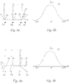
- Fig. 3a shows a schematic representation of a cross section of a composite of a multiplicity of different micro-optical elements 3a to 3x, which are assembled to form a surface 1a.
- Figure 3b shows an exemplary light intensity distribution resulting from the combination of the micro-optical elements 3a to 3x Fig. 3a . This is, for example, a normal distribution.
- Figure 4a shows a schematic representation of a cross section of a composite of a plurality of different micro-optical elements 3a 'to 3x', which in contrast to Figures 1a to 3b are these micro-optical elements 3a 'to 3x' are not designed to be reflective, but rather translucent and thus refractive.
- Figure 4b shows an exemplary light intensity distribution resulting from the combination of the micro-optical elements 3a 'to 3x' Figure 4a ,
- Figure 5a shows an exemplary light intensity distribution that can be achieved through targeted design and arrangement of the micro-optical elements.
- This shows, for example, a distribution for an angle of incidence of 90 °, with the surface 1a and consequently the BSDF distribution selected in such a way that at least one local maximum I 1 is formed in this BSDF distribution function, which corresponds to an adjacent value I 2 that is around + 5 ° or -5 ° to the angular value of the local maximum is offset, in terms of height by at least 40%.
- this value I 2 is exceeded by more than 100%.
- the distribution according to Figure 5a has, for example, four strongly pronounced maxima (at approx. +/- 40 ° and +/- 70 °) and a less pronounced maximum at 0 °.
- Figures 5b and 5c each show an example of a combination of different micro-optical elements that can be used to generate different light intensity distributions.
- Figure 6a shows an optically relevant component 1 comprising a surface 1 a, which was calculated and designed according to a method according to the invention.
- Figures 6b to 6h show two-dimensional light intensity distributions across the surface Figure 6a for different angles of incidence of light - from which a BSDF distribution can be derived.
- Fig. 7 shows the individual steps of the method according to the invention in a block diagram.
Landscapes
- Physics & Mathematics (AREA)
- General Physics & Mathematics (AREA)
- Optics & Photonics (AREA)
- Engineering & Computer Science (AREA)
- General Engineering & Computer Science (AREA)
- Non-Portable Lighting Devices Or Systems Thereof (AREA)
Priority Applications (5)
| Application Number | Priority Date | Filing Date | Title |
|---|---|---|---|
| EP20171071.2A EP3901686A1 (de) | 2020-04-23 | 2020-04-23 | Verfahren zur berechnung eines optisch relevanten kraftfahrzeugbauteils mit einer lichtstreuenden oberfläche |
| PCT/EP2021/056848 WO2021213739A1 (de) | 2020-04-23 | 2021-03-17 | Verfahren zur berechnung eines optisch relevanten kraftfahrzeugbauteils mit einer lichtstreuenden oberfläche |
| EP21712497.3A EP4139736A1 (de) | 2020-04-23 | 2021-03-17 | Verfahren zur berechnung eines optisch relevanten kraftfahrzeugbauteils mit einer lichtstreuenden oberfläche |
| CN202180030046.6A CN115380235A (zh) | 2020-04-23 | 2021-03-17 | 用于计算具有光散射表面的光学相关的机动车部件的方法 |
| KR1020227033560A KR20220141895A (ko) | 2020-04-23 | 2021-03-17 | 광확산 표면을 포함하는 광학 관련 자동차 부품의 계산 방법 |
Applications Claiming Priority (1)
| Application Number | Priority Date | Filing Date | Title |
|---|---|---|---|
| EP20171071.2A EP3901686A1 (de) | 2020-04-23 | 2020-04-23 | Verfahren zur berechnung eines optisch relevanten kraftfahrzeugbauteils mit einer lichtstreuenden oberfläche |
Publications (1)
| Publication Number | Publication Date |
|---|---|
| EP3901686A1 true EP3901686A1 (de) | 2021-10-27 |
Family
ID=70417445
Family Applications (2)
| Application Number | Title | Priority Date | Filing Date |
|---|---|---|---|
| EP20171071.2A Withdrawn EP3901686A1 (de) | 2020-04-23 | 2020-04-23 | Verfahren zur berechnung eines optisch relevanten kraftfahrzeugbauteils mit einer lichtstreuenden oberfläche |
| EP21712497.3A Pending EP4139736A1 (de) | 2020-04-23 | 2021-03-17 | Verfahren zur berechnung eines optisch relevanten kraftfahrzeugbauteils mit einer lichtstreuenden oberfläche |
Family Applications After (1)
| Application Number | Title | Priority Date | Filing Date |
|---|---|---|---|
| EP21712497.3A Pending EP4139736A1 (de) | 2020-04-23 | 2021-03-17 | Verfahren zur berechnung eines optisch relevanten kraftfahrzeugbauteils mit einer lichtstreuenden oberfläche |
Country Status (4)
| Country | Link |
|---|---|
| EP (2) | EP3901686A1 (zh) |
| KR (1) | KR20220141895A (zh) |
| CN (1) | CN115380235A (zh) |
| WO (1) | WO2021213739A1 (zh) |
-
2020
- 2020-04-23 EP EP20171071.2A patent/EP3901686A1/de not_active Withdrawn
-
2021
- 2021-03-17 CN CN202180030046.6A patent/CN115380235A/zh active Pending
- 2021-03-17 WO PCT/EP2021/056848 patent/WO2021213739A1/de unknown
- 2021-03-17 EP EP21712497.3A patent/EP4139736A1/de active Pending
- 2021-03-17 KR KR1020227033560A patent/KR20220141895A/ko unknown
Non-Patent Citations (2)
| Title |
|---|
| CHOI, MYONG JO: "Simulation of Backlight Using Bidirectional Scattering Distribution Function", SID SYMPOSIUM 2010, SEATTLE, USA, SID, CAMPBELL, CA, USA, 23 May 2010 (2010-05-23), XP001565076 * |
| ZHDANOV DMITRY D ET AL: "Efficient methods of BSDF reconstruction from the micro-relief dataset for the lighting simulation tasks", PROCEEDINGS OF SPIE; [PROCEEDINGS OF SPIE ISSN 0277-786X VOLUME 10524], SPIE, US, vol. 10693, 28 May 2018 (2018-05-28), pages 1069310 - 1069310, XP060105575, ISBN: 978-1-5106-1533-5, DOI: 10.1117/12.2312637 * |
Also Published As
| Publication number | Publication date |
|---|---|
| EP4139736A1 (de) | 2023-03-01 |
| KR20220141895A (ko) | 2022-10-20 |
| CN115380235A (zh) | 2022-11-22 |
| WO2021213739A1 (de) | 2021-10-28 |
Similar Documents
| Publication | Publication Date | Title |
|---|---|---|
| DE69938614T2 (de) | Lichtleiter zur Hintergrundbeleuchtung eines Flachbildschirms | |
| EP3714205B1 (de) | Lichtmodul für einen kraftfahrzeugscheinwerfer | |
| EP2344362B1 (de) | Lichtleitelement für eine beleuchtungseinrichtung | |
| EP2112039B1 (de) | Optische Sensorvorrichtung | |
| DE602004002746T2 (de) | Lichtvorrichtung, insbesondere Leuchtplatte für Verkehrszeichen oder Informationen für die Öffentlichkeit, oder eine Kraftfahrzeugleuchte. | |
| DE102010027322A1 (de) | Mikrooptik für angenähert transversalisotrope Aufweitung einer Scheinwerferlichtverteilung | |
| EP1743204A1 (de) | Vorrichtung und verfahren zur optischen strahlhomogenisierung | |
| DE102014112891B4 (de) | Optisches Element und optoelektronisches Bauelement | |
| EP3091273B1 (de) | Optische struktur für signlight | |
| DE102011112285A1 (de) | Lichtformung mittels LED-Lichtquelle | |
| EP2959331B1 (de) | Elektromagnetische strahlung streuendes element | |
| EP3671304A1 (de) | Verfahren zur konstruktion eines optischen elements für einen kraftfahrzeugscheinwerfer | |
| DE102011011462A1 (de) | Lichtleitelement mit Auskoppelstellen | |
| DE102018117569A1 (de) | Retroreflektor | |
| EP2238496B1 (de) | Optoelektronische vorrichtung und bildaufnahmegerät | |
| DE10324402A1 (de) | Optische Vorrichtung mit vielen Gruppierungen Eindimensionaler optischer Elemente | |
| WO2016124561A1 (de) | Optisch variables sicherheitselement | |
| EP3901686A1 (de) | Verfahren zur berechnung eines optisch relevanten kraftfahrzeugbauteils mit einer lichtstreuenden oberfläche | |
| WO2018185218A2 (de) | Vorrichtung zur darstellung eines bildes | |
| DE10214566B4 (de) | Homogen paralleles Licht emittierende Leuchtdiode | |
| DE102018207516B3 (de) | Head-Up-Display mit einer von mehreren verteilt angeordneten Lichtquellen beleuchteten Anzeige | |
| EP2347173B1 (de) | Beleuchtungseinrichtung mit reduzierter blendwirkung | |
| DE3013141C2 (de) | Verfahren und Vorrichtung zum optischen Anzeigen von Farblicht-Informationen | |
| AT520942A4 (de) | Verfahren zur Herstellung einer Lichtlenkfolie und damit hergestellte Folie | |
| DE112021001154T5 (de) | Reflektor |
Legal Events
| Date | Code | Title | Description |
|---|---|---|---|
| PUAI | Public reference made under article 153(3) epc to a published international application that has entered the european phase |
Free format text: ORIGINAL CODE: 0009012 |
|
| STAA | Information on the status of an ep patent application or granted ep patent |
Free format text: STATUS: THE APPLICATION HAS BEEN PUBLISHED |
|
| AK | Designated contracting states |
Kind code of ref document: A1 Designated state(s): AL AT BE BG CH CY CZ DE DK EE ES FI FR GB GR HR HU IE IS IT LI LT LU LV MC MK MT NL NO PL PT RO RS SE SI SK SM TR |
|
| B565 | Issuance of search results under rule 164(2) epc |
Effective date: 20201002 |
|
| STAA | Information on the status of an ep patent application or granted ep patent |
Free format text: STATUS: THE APPLICATION IS DEEMED TO BE WITHDRAWN |
|
| 18D | Application deemed to be withdrawn |
Effective date: 20220429 |