EP3901686A1 - Method for calculating an optically relevant motor vehicle component with a light-scattering surface - Google Patents
Method for calculating an optically relevant motor vehicle component with a light-scattering surface Download PDFInfo
- Publication number
- EP3901686A1 EP3901686A1 EP20171071.2A EP20171071A EP3901686A1 EP 3901686 A1 EP3901686 A1 EP 3901686A1 EP 20171071 A EP20171071 A EP 20171071A EP 3901686 A1 EP3901686 A1 EP 3901686A1
- Authority
- EP
- European Patent Office
- Prior art keywords
- micro
- optical elements
- distribution
- light
- motor vehicle
- Prior art date
- Legal status (The legal status is an assumption and is not a legal conclusion. Google has not performed a legal analysis and makes no representation as to the accuracy of the status listed.)
- Withdrawn
Links
Images


Classifications
-
- G—PHYSICS
- G02—OPTICS
- G02B—OPTICAL ELEMENTS, SYSTEMS OR APPARATUS
- G02B27/00—Optical systems or apparatus not provided for by any of the groups G02B1/00 - G02B26/00, G02B30/00
- G02B27/0012—Optical design, e.g. procedures, algorithms, optimisation routines
-
- F—MECHANICAL ENGINEERING; LIGHTING; HEATING; WEAPONS; BLASTING
- F21—LIGHTING
- F21V—FUNCTIONAL FEATURES OR DETAILS OF LIGHTING DEVICES OR SYSTEMS THEREOF; STRUCTURAL COMBINATIONS OF LIGHTING DEVICES WITH OTHER ARTICLES, NOT OTHERWISE PROVIDED FOR
- F21V7/00—Reflectors for light sources
- F21V7/04—Optical design
Definitions
- the invention relates to a method for calculating an optically relevant motor vehicle component with a light-scattering surface.
- the invention further relates to an optically relevant motor vehicle component produced by the method according to the invention.
- the invention further relates to a motor vehicle headlight, comprising an optically relevant motor vehicle component according to the invention.
- the invention also relates to a motor vehicle, comprising an optically relevant motor vehicle component according to the invention and / or a motor vehicle headlight according to the invention.
- One object of the invention is to create a possibility with which the scattering behavior of a light-scattering surface can be specified, and yet micro-optics are arranged in such a way that the optical impression of a diffuse surface is created.
- surface structures e.g. grain-like
- scattering behavior can be specified by a lighting technician, but which do not reveal any regular patterns or structures in their appearance.
- the scattering behavior of the optically relevant component can be specified in a targeted manner and thus optimized with regard to the desired application. The emission of false light can thus be largely avoided.
- optically relevant motor vehicle component is understood to mean an optically relevant component that is intended for use in a motor vehicle.
- optically relevant component is understood to mean a component that has the following properties: An optically relevant component influences the propagation of light that is either emitted by the optically relevant component itself or that impinges on it, with the optically relevant component as well This incident light interacts and subsequently emits light.
- An optically relevant component is, for example, a light source, in particular an LED and / or a laser light source, a diaphragm or diaphragm arrangements, a reflector, a lens, in particular a projection lens, a light guide, thick-wall optics, a prism, an optical grating, a mirror, a MEMS component designed as a DMD chip, and / or an entire light module or assemblies comprising such components, etc. are considered. It is also possible for individual or a plurality of these components mentioned to form the optically relevant component.
- the optically relevant component can for example be held in a support frame and / or adjustable with the aid of an adjustment system, the adjustment system being able to act on the optically relevant component or the support frame for this purpose, for example.
- BxDF distributions are higher dimensional tensors that can be interpreted as a transfer function between the incoming light beam and the outgoing light beam.
- the BxDF functions therefore map every possible incident light beam onto the solid angle.
- the BSDF function can be a combination of BRDF and BTDF and thus encompass the entire solid angle.
- a BSDF distribution can be understood as a function that can output a distribution for each light beam incident on a surface, which indicates how great the probability is that this light beam will be scattered in a certain spatial direction.
- At least individual micro-optic elements are pyramid-shaped, with adjacent pyramid-shaped micro-optic elements being arranged seamlessly next to one another.
- At least individual micro-optic elements are designed to be conical.
- micro-optical elements can be designed in the shape of a pyramid or a cone.
- the inclination of the reflection surface or transmission surface of the micro-optics is between 0 ° and 45 °, the maximum of the inclination preferably being between 40 ° and 45 °.
- the maximum of the inclination preferably being between 40 ° and 45 °.
- a slope of 45 ° it is a reflection with an angle of 180 ° is already possible through double reflection with reference to an adjacent micro-optic element.
- the surface according to step a) has light-reflecting micro-optical elements, the BSDF distribution being selected in such a way that at least one local maximum is formed in this BSDF distribution function, which corresponds to a neighboring value that is + 5 ° or - 5 ° to the angular value of the local maximum is offset in terms of height by at least 40%.
- steps d1) to d5) are repeated iteratively, an additional part of the BSDF distribution being taken into account for each repetition.
- the surface diagonal of the base surface of the micro-optical element has a length between 350 nm and 2 mm. In the case of micro-optic element lengths below 350 nm, interference effects would already have to be taken into account.
- step d4) a manipulation of the optical appearance of the micro-optical elements takes place in that the geometric shape of individual micro-optical elements is formed as a protrusion and the geometric shape of other micro-optical elements is formed as a recess.
- This is achieved, for example, by inverting the micro-optical element (i.e. the formation of a recess instead of a protrusion; this can make the surface look even more irregular).
- the optically relevant motor vehicle component has an optically effective light-scattering total area, which is composed of optically effective light-scattering sub-areas, each optically effective light-scattering sub-area having a predeterminable BSDF distribution and a suitable selection of micro-optic elements which, according to the method according to one of the preceding claims, wherein the algorithm is also set up to take into account the BSDF distribution of adjacent partial areas and to select the individual micro-optical elements of the adjacent partial areas in the transition area of the partial areas in such a way and to group them in the transition area so that visually (ie with the naked eye) recognizable differences in the distribution of the micro-optics between the adjacent partial areas are minimized.
- the micro-optical elements are formed on a plastic carrier or a glass carrier, the micro-optical elements being made reflective in that the surface of the plastic or glass carrier is coated reflectively by means of aluminum vapor deposition.
- the plastic carrier consists of polycarbonate or PMMA.
- the invention further relates to an optically relevant motor vehicle component produced by the method according to the invention.
- the invention further relates to a motor vehicle headlight, comprising an optically relevant motor vehicle component according to the invention.
- it can also be a signal light device, in particular a direction indicator.
- the invention further relates to a motor vehicle, comprising an optically relevant motor vehicle component according to the invention and / or a motor vehicle headlight according to the invention.
- optional aspects of the invention can also be described as follows: Small micro-optics that cannot or can hardly be resolved with the naked eye are calculated on the surface.
- an approach is used that is unusual compared to previous optics or has never been used: Each optic is unique and independently calculated and has a different behavior than the other optics of the surface. In total, however, all optics in a certain area are calculated in such a way that as a whole they result in a defined BSDF distribution (scattering behavior). In the previous approach, optics are calculated in such a way that each optic depicts the entire light distribution as far as possible. With the stochastic approach used here, every optic only does a targeted small part of the light distribution. The total light distribution then results from the sum of the individual optics.
- Each optic differs from the other optics in terms of its shape and appearance, which means that a random variation in the visible surface texture can be achieved.
- the optics are randomly distributed over the calculated area, so that no regular pattern is formed on the surface and the structure in the visual appearance corresponds to a random scattered structure or grain.
- This variation (inversion) of random optics offers another possibility to break up visible structures.
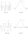
- Fig. 1a shows a schematic representation of a cross section of micro-optical elements 3a.
- the micro-optical elements 3a are on the surface of an optically relevant motor vehicle component 1 (see Figure 6a ) arranged.
- the component 1 according to Figure 6a can in principle have any dimensions, for example length and width can vary between a few millimeters up to meters, the component 1 according to Figure 6a has a length and width between 2 to 3 cm each.
- Several thousand to million micro-optical elements, for example can therefore be arranged on the surface, which - these are very small in the present example - cannot be individually identified in the illustration shown.
- Figure 1b shows exemplary light beams L 1 and L 2 which are incident on a micro-optical element 3a according to FIG Fig. 1a strike and be reflected. These light rays are incident at an angle of incidence of 90 °, for example.
- the horizontal dashed line is intended to show the essentially straight course of the reflection surface 1a, which deviates from an exactly straight course only due to the unevenness of the numerous micro-optics.
- the light beam L 2 is reflected in an analogous manner.
- the corresponding angles to L 1 agree due to the symmetrical structure of the micro-optical element 3a, except that the light beam L 2 is deflected to the right and not to the left.
- an asymmetrical geometry could also be provided.
- Figure 1c shows the reflection behavior of the micro-optics 3a.
- Figure 1c an exemplary light intensity distribution (ie a section from a BSDF distribution - namely for an angle of incidence 90 °) of the micro-optical elements 3a according to FIG Figures 1a and 1b .
- Fig. 2a shows a schematic representation of a cross section of a composite of different micro-optical elements 3a and 3b.
- Figure 2b shows exemplary light beams which are incident on a micro-optical element 3b according to FIG Fig. 2a hit.
- FIG Figure 2c Assuming that the surface 1a consists only of the two micro-optical elements 3a and 3b, and that these are distributed in an area ratio of 2: 1, an exemplary light intensity distribution of the reflected light would result according to FIG Figure 2c whereby the light is incident on the surface 1a at an angle of 90 °. The intensity of the light that is reflected at an angle of +/- 40 ° would be half as strong as the intensity of the light that is reflected at an angle of +/- 70 °.
- the relevant micro-optical elements have a pyramid shape, with adjacent pyramid-shaped micro-optical elements being arranged seamlessly next to one another.
- individual micro-optic elements could also be conical (see Figure 5c ).
- Fig. 3a shows a schematic representation of a cross section of a composite of a multiplicity of different micro-optical elements 3a to 3x, which are assembled to form a surface 1a.
- Figure 3b shows an exemplary light intensity distribution resulting from the combination of the micro-optical elements 3a to 3x Fig. 3a . This is, for example, a normal distribution.
- Figure 4a shows a schematic representation of a cross section of a composite of a plurality of different micro-optical elements 3a 'to 3x', which in contrast to Figures 1a to 3b are these micro-optical elements 3a 'to 3x' are not designed to be reflective, but rather translucent and thus refractive.
- Figure 4b shows an exemplary light intensity distribution resulting from the combination of the micro-optical elements 3a 'to 3x' Figure 4a ,
- Figure 5a shows an exemplary light intensity distribution that can be achieved through targeted design and arrangement of the micro-optical elements.
- This shows, for example, a distribution for an angle of incidence of 90 °, with the surface 1a and consequently the BSDF distribution selected in such a way that at least one local maximum I 1 is formed in this BSDF distribution function, which corresponds to an adjacent value I 2 that is around + 5 ° or -5 ° to the angular value of the local maximum is offset, in terms of height by at least 40%.
- this value I 2 is exceeded by more than 100%.
- the distribution according to Figure 5a has, for example, four strongly pronounced maxima (at approx. +/- 40 ° and +/- 70 °) and a less pronounced maximum at 0 °.
- Figures 5b and 5c each show an example of a combination of different micro-optical elements that can be used to generate different light intensity distributions.
- Figure 6a shows an optically relevant component 1 comprising a surface 1 a, which was calculated and designed according to a method according to the invention.
- Figures 6b to 6h show two-dimensional light intensity distributions across the surface Figure 6a for different angles of incidence of light - from which a BSDF distribution can be derived.
- Fig. 7 shows the individual steps of the method according to the invention in a block diagram.
Landscapes
- Physics & Mathematics (AREA)
- General Physics & Mathematics (AREA)
- Optics & Photonics (AREA)
- Engineering & Computer Science (AREA)
- General Engineering & Computer Science (AREA)
- Non-Portable Lighting Devices Or Systems Thereof (AREA)
Abstract
Die Erfindung betrifft ein Verfahren zur Berechnung eines optisch relevanten Kraftfahrzeugbauteils (1) mit einer lichtstreuenden Oberfläche (1a), umfassend die folgenden Schritte:a) Auswahl einer vorgebbaren BSDF-Verteilung (2) der lichtstreuenden Oberfläche (1a) des optischen relevanten Kraftfahrzeugbauteils (1), wobei die lichtstreuende Oberfläche (1a) aus lichtstreuenden Mikrooptikelementen (3a, 3b, ...3x) zusammengesetzt ist,b) Auswahl der Information, ob die lichtstreuende Oberfläche (1a) entweder ausschließlich reflektiv lichtstreuend wirkt, oder ob ein transmittierender Anteil vorhanden ist, wobei im Falle des Vorliegens eines transmittierenden Anteils zudem ein Schritt b1) folgt, wonach zur Berücksichtigung des Brechungsindex eine Auswahl eines Materials, aus dem die Oberfläche (1a) zusammengesetzt ist, erfolgt,c) Auswahl eines den Größenbereich der Mikrooptikelemente (3a, 3b, ...3x) vorgebenden Parameters aus einem vorgebbaren Wahlbereich,d) Berechnen von unterschiedlichen Formen von Mikrooptikelementen (3a, 3b, ...3x) und derer Mengenverteilung gemäß einem Algorithmus (4) zur Erzielung der gemäß Schritt a) ausgewählten BSDF-Verteilung unter Berücksichtigung der ausgewählten Größenbereichs gemäß Schritt c) sowie gegebenenfalls der optischen Eigenschaften des Materials gemäß Schritt b1), wobei die Oberfläche gemäß Schritt a) aus einer Vielzahl an nebeneinander flächig angeordneten Mikrooptikelementen (3a, 3b, ...3x) zusammengesetzt ist, die aus dem Material gemäß Schritt c) bestehen, wobei der Algorithmus folgende Teilschritte umfasst:d1) Heranziehen zumindest eines Teils der BSDF-Verteilung,d2) Aufteilen der Verteilung nach Schritt d1) in winkelabhängige Teilbereiche,d3) Berechnen der geometrischen Form der Reflexions- oder Transmissionsflächen von Mikrooptikelementen für jeden Teilbereich,d4) Bestimmen des mengenmäßigen Anteils der Mikrooptikelemente für jeden Teilbereich in Abhängigkeit von dem Wert der Verteilungsfunktion für den Teilbereich,d5) randomisierte Verteilung (Pa, Pb, ...Px) der gemäß Schritt d4) bestimmten Mikrooptikelemente (3a, 3b, ...3x) auf die Oberfläche (1a) des optisch relevanten Kraftfahrzeugbauteils (1),e) Ausgabe des Berechnungsergebnisses gemäß Schritt d) in Form digitaler Daten (D).The invention relates to a method for calculating an optically relevant motor vehicle component (1) with a light-scattering surface (1a), comprising the following steps: ), whereby the light-scattering surface (1a) is composed of light-scattering micro-optical elements (3a, 3b, ... 3x), b) Selection of the information whether the light-scattering surface (1a) either only has a reflective, light-scattering effect, or whether a transmitting part is present is, in the case of the presence of a transmitting portion also a step b1) follows, after which a material from which the surface (1a) is composed is selected in order to take into account the refractive index, c) selection of a size range of the micro-optical elements (3a, 3b, ... 3x) prescribing parameters from a prescribable selection range, d) calculating different For Men of micro-optical elements (3a, 3b, ... 3x) and their quantity distribution according to an algorithm (4) to achieve the BSDF distribution selected according to step a), taking into account the selected size range according to step c) and, if applicable, the optical properties of the material according to Step b1), the surface according to step a) being composed of a large number of micro-optical elements (3a, 3b, ... 3x) arranged flat next to one another, which consist of the material according to step c), the algorithm comprising the following substeps: d1 ) Using at least part of the BSDF distribution, d2) dividing the distribution according to step d1) into angle-dependent sub-areas, d3) calculating the geometric shape of the reflection or transmission surfaces of micro-optical elements for each sub-area, d4) determining the quantitative proportion of micro-optical elements for each Sub-area as a function of the value of the distribution function for the sub-area, d5) randomis ierte distribution (Pa, Pb, ... Px) of the micro-optical elements (3a, 3b, ... 3x) determined in accordance with step d4) on the surface (1a) of the optically relevant motor vehicle component (1), e) output of the calculation result in accordance with step d) in the form of digital data (D).
Description
Die Erfindung betrifft ein Verfahren zur Berechnung eines optisch relevanten Kraftfahrzeugbauteils mit einer lichtstreuenden Oberfläche.The invention relates to a method for calculating an optically relevant motor vehicle component with a light-scattering surface.
Die Erfindung betrifft weiters ein optisch relevantes Kraftfahrzeugbauteil hergestellt nach dem erfindungsgemäßen Verfahren.The invention further relates to an optically relevant motor vehicle component produced by the method according to the invention.
Weiters betrifft die Erfindung einen Kraftfahrzeugscheinwerfer, umfassend ein erfindungsgemäßes optisch relevantes Kraftfahrzeugbauteil.The invention further relates to a motor vehicle headlight, comprising an optically relevant motor vehicle component according to the invention.
Die Erfindung betrifft zudem ein Kraftfahrzeug, umfassend ein erfindungsgemäßes optisch relevantes Kraftfahrzeugbauteil und/oder einen erfindungsgemäßen Kraftfahrzeugscheinwerfer.The invention also relates to a motor vehicle, comprising an optically relevant motor vehicle component according to the invention and / or a motor vehicle headlight according to the invention.
Aus dem Stand der Technik ist es bekannt, Oberflächen von optischen Strukturen zu narben um Verbesserungen von Lichtfunktionen bezüglich Homogenität, Streulicht, räumliche Sichtbarkeit, oder ähnlichem zu erzielen. Diese Narbungen sind üblicherweise komplett zufällig und nicht für lichttechnische Anwendungsgebiete optimiert. Die Narbungen sind in diesen Fällen lichttechnisch undefiniert. Daraus resultiert ein undefiniertes Streuverhalten. Als Resultat sind die dadurch entstehenden Lichtverteilungen sehr ineffizient, weil Licht ebenso in ungewünschte Bereiche gestreut wird. Soll hingegen eine gezieltes Streuverhalten erreicht werden, so wurden im Stand der Technik hierfür entsprechende regelmäßige Strukturen geschaffen, die zudem regemäßig angeordnet waren. Eine solcherart ausgebildete Oberfläche wirkt nicht mehr "unregelmäßig" und "diffus", sondern lässt sich mit freiem Auge als regelmäßig strukturierte Fläche erkennen.It is known from the prior art to grain surfaces of optical structures in order to achieve improvements in light functions with regard to homogeneity, scattered light, spatial visibility, or the like. These grains are usually completely random and not optimized for lighting applications. In these cases, the grains are undefined in terms of light technology. This results in an undefined spreading behavior. As a result, the resulting light distributions are very inefficient because light is also scattered into undesired areas. If, on the other hand, a targeted scattering behavior is to be achieved, corresponding regular structures were created in the prior art, which were also regularly arranged. A surface designed in this way no longer appears "irregular" and "diffuse", but can be seen with the naked eye as a regularly structured surface.
Eine Aufgabe der Erfindung besteht darin, eine Möglichkeit zu schaffen, mit der das streuverhalten einer lichtstreuenden Oberfläche vorgegeben werden kann, und dennoch Mikrooptiken dergestalt angeordnet sind, der optische Eindruck einer diffusen Fläche entsteht.One object of the invention is to create a possibility with which the scattering behavior of a light-scattering surface can be specified, and yet micro-optics are arranged in such a way that the optical impression of a diffuse surface is created.
Diese Aufgabe wird mit einem Verfahren der eingangs genannten Art gelöst, welches erfindungsgemäß die folgenden Schritte umfasst:
- a) Auswahl einer vorgebbaren BSDF-Verteilung der lichtstreuenden Oberfläche des optischen relevanten Kraftfahrzeugbauteils, wobei die lichtstreuende Oberfläche aus lichtstreuenden Mikrooptikelementen zusammengesetzt ist,
- b) Auswahl der Information, ob die lichtstreuende Oberfläche entweder ausschließlich reflektiv lichtstreuend wirkt, oder ob ein transmittierender Anteil vorhanden ist, wobei im Falle des Vorliegens eines transmittierenden Anteils zudem ein Schritt b1) folgt, wonach zur Berücksichtigung des Brechungsindex eine Auswahl eines Materials, aus dem die Oberfläche zusammengesetzt ist, erfolgt,
- c) Auswahl eines den Größenbereich der Mikrooptikelemente vorgebenden Parameters aus einem vorgebbaren Wahlbereich,
- d) Berechnen von unterschiedlichen Formen von Mikrooptikelementen und derer Mengenverteilung gemäß einem Algorithmus zur Erzielung der gemäß Schritt a) ausgewählten BSDF-Verteilung unter Berücksichtigung der ausgewählten Größenbereichs gemäß Schritt c) sowie gegebenenfalls der optischen Eigenschaften des Materials gemäß Schritt b1), wobei die Oberfläche gemäß Schritt a) aus einer Vielzahl an nebeneinander flächig angeordneten Mikrooptikelementen zusammengesetzt ist, die aus dem Material gemäß Schritt c) bestehen, wobei der Algorithmus folgende Teilschritte umfasst:
- d1) Heranziehen zumindest eines Teils der BSDF-Verteilung
- d2) Aufteilen der Verteilung nach Schritt d1) in winkelabhängige Teilbereiche,
- d3) Berechnen der geometrischen Form der Reflexions- oder Transmissionsflächen von Mikrooptikelementen für jeden Teilbereich (d.h. für jeden Teilbereich werden die hierfür erforderlichen geometrischen Formen der Mikrooptikelemente berechnet),
- d4) Bestimmen des mengenmäßigen Anteils der Mikrooptikelemente für jeden Teilbereich in Abhängigkeit von dem Wert der Verteilungsfunktion für den Teilbereich (d.h. es wird z.B. das Mengenverhältnis im Vergleich zu anderen Teilbereichen bestimmt),
- d5) randomisierte Verteilung der gemäß Schritt d4) bestimmten Mikrooptikelemente auf die Oberfläche des optisch relevanten Kraftfahrzeugbauteils,
- e) Ausgabe des Berechnungsergebnisses gemäß Schritt d) in Form digitaler Daten.
- a) Selection of a predeterminable BSDF distribution of the light-scattering surface of the optically relevant motor vehicle component, the light-scattering surface being composed of light-scattering micro-optical elements,
- b) Selection of the information as to whether the light-scattering surface either only has a reflective, light-scattering effect or whether a transmitting component is present, with a step b1) also following if a transmitting component is present, after which a material is selected to take into account the refractive index which the surface is composed, takes place,
- c) Selection of a parameter that specifies the size range of the micro-optical elements from a specifiable selection range,
- d) Calculating different shapes of micro-optical elements and their quantity distribution according to an algorithm to achieve the BSDF distribution selected according to step a), taking into account the selected size range according to step c) and, if applicable, the optical properties of the material according to step b1), the surface according to Step a) is composed of a large number of micro-optical elements arranged flat next to one another, which consist of the material according to step c), the algorithm comprising the following sub-steps:
- d1) using at least part of the BSDF distribution
- d2) dividing the distribution according to step d1) into angle-dependent sub-areas,
- d3) Calculating the geometric shape of the reflection or transmission surfaces of micro-optic elements for each sub-area (ie the required geometric shapes of the micro-optic elements are calculated for each sub-area),
- d4) determining the quantitative proportion of the micro-optical elements for each sub-area as a function of the value of the distribution function for the sub-area (that is, for example, the quantitative ratio is determined in comparison to other sub-areas),
- d5) randomized distribution of the micro-optical elements determined according to step d4) on the surface of the optically relevant motor vehicle component,
- e) Output of the calculation result according to step d) in the form of digital data.
Auf diese Weise können (z.B. narbungsähnliche) Oberflächenstrukturen erstellt werden, deren Streuverhalten von einem Lichttechniker vorgegeben werden kann, die aber in ihrem Aussehen keine regelmäßigen Muster oder Strukturen erkennen lassen. Das Streuverhalten kann des optisch relevanten Bauteils kann dabei gezielt vorgegeben und so hinsichtlich der gewünschten Anwendung optimiert werden. Die Abstrahlung von Fehllicht kann somit weitgehend vermieden werden.In this way, surface structures (e.g. grain-like) can be created whose scattering behavior can be specified by a lighting technician, but which do not reveal any regular patterns or structures in their appearance. The scattering behavior of the optically relevant component can be specified in a targeted manner and thus optimized with regard to the desired application. The emission of false light can thus be largely avoided.
Unter dem Ausdruck "optisch relevantes Kraftfahrzeugbauteil" wird ein optisch relevantes Bauteil verstanden, dass für die Anwendung in einem Kraftfahrzeug bestimmt ist. Unter dem Ausdruck "optisch relevantes Bauteil" wird ein Bauteil verstanden, das folgende Eigenschaften aufweist: Ein optisch relevantes Bauteil beeinflusst die Ausbreitung von Licht, das entweder durch das optisch relevante Bauteil selbst emittiert wird, oder auf dieses auftrifft, wobei das optisch relevante Bauteil mit diesem auftreffenden Licht wechselwirkt und in weiterer Folge Licht abstrahlt. Als ein optisch relevantes Bauteil wird beispielsweise eine Lichtquelle, insbesondere eine LED und/oder eine Laserlichtquelle, eine Blende oder Blendenanordnungen, ein Reflektor, eine Linse, insbesondere eine Projektionslinse, ein Lichtleiter, eine Dickwandoptik, ein Prisma, ein optisches Gitter, ein Spiegel, ein als DMD-Chip ausgebildetes MEMS-Bauteil, und/oder ein ganzes Lichtmodule bzw. Baugruppen umfassend solche Komponenten, etc. angesehen. Es können auch einzelne oder eine Mehrzahl dieser genannten Komponenten das optisch relevante Bauteil ausbilden. Das optisch relevante Bauteil kann beispielsweise in einem Tragrahmen gehaltert sein und/oder mit Hilfe eines Einstellsystems einstellbar sein, wobei das Einstellsystem hierzu beispielsweise an dem optisch relevanten Bauteil oder dem Tragrahmen angreifen kann.The expression “optically relevant motor vehicle component” is understood to mean an optically relevant component that is intended for use in a motor vehicle. The expression “optically relevant component” is understood to mean a component that has the following properties: An optically relevant component influences the propagation of light that is either emitted by the optically relevant component itself or that impinges on it, with the optically relevant component as well This incident light interacts and subsequently emits light. An optically relevant component is, for example, a light source, in particular an LED and / or a laser light source, a diaphragm or diaphragm arrangements, a reflector, a lens, in particular a projection lens, a light guide, thick-wall optics, a prism, an optical grating, a mirror, a MEMS component designed as a DMD chip, and / or an entire light module or assemblies comprising such components, etc. are considered. It is also possible for individual or a plurality of these components mentioned to form the optically relevant component. The optically relevant component can for example be held in a support frame and / or adjustable with the aid of an adjustment system, the adjustment system being able to act on the optically relevant component or the support frame for this purpose, for example.
BxDF Verteilungen sind höherdimensionale Tensoren, die als Transferfunktion zwischen Einfallendem Lichtstrahl und Ausfallendem Lichtstrahl interpretiert werden können. Die BxDF Funktionen bilden also jeden möglichen, einfallenden Lichtstrahl auf den Raumwinkel ab. Die BRDF Funktion auf den reflektierten Halbraum, die BTDF Funktion auf den Transmittierten Halbraum. Die BSDF Funktion kann eine Kombination aus BRDF und BTDF sein und somit den gesamten Raumwinkel umfassen. Eine BSDF Verteilung kann als eine Funktion auffasst, die für jeden auf eine Fläche auffallenden Lichtstrahl eine Verteilung ausgeben kann, die angibt wie groß die Wahrscheinlichkeit ist, dass dieser Lichtstrahl in eine gewisse Raumrichtung gestreut wird. Und da in der Praxis eine enorme Menge an Photonen auf die betreffende Fläche eintrifft, ist diese Streuwahrscheinlichkeit gleichbedeutend mit der gestreuten Lichtintensität, weil bei einer Lichtmessung das Gesetz der Großen zahlen immer erfüllt ist. Man bekommt also für jeden Einfallswinkel eine Lichtintensitätsverteilung. Die BSDF Verteilung setzt jeden möglichen, einfallenden Lichtstrahl mit allen möglichen Ausfallswinkeln in Relation. Sinnvoll visualisieren kann man aber immer nur einen Ausschnitt aus der BSDF - sprich ein Abstrahlungsverhalten für einen bestimmten Einfallswinkel.BxDF distributions are higher dimensional tensors that can be interpreted as a transfer function between the incoming light beam and the outgoing light beam. The BxDF functions therefore map every possible incident light beam onto the solid angle. The BRDF function on the reflected half-space, the BTDF function on the transmitted half-space. The BSDF function can be a combination of BRDF and BTDF and thus encompass the entire solid angle. A BSDF distribution can be understood as a function that can output a distribution for each light beam incident on a surface, which indicates how great the probability is that this light beam will be scattered in a certain spatial direction. And since in practice an enormous amount of photons hits the surface in question, this scatter probability is synonymous with the scattered light intensity, because the law of large numbers is always fulfilled when measuring light. So you get a light intensity distribution for every angle of incidence. The BSDF distribution relates every possible incident light beam to all possible angles of reflection. However, you can only visualize a section of the BSDF in a meaningful way - i.e. a radiation behavior for a certain angle of incidence.
Die randomisierte Verteilung gemäß dem Algorithmus nach Schritt d), insbesondere Schritt d5) kann beispielsweise in folgenden Teilschritten erfolgen:
- 1. Unterteilung der Gesamtfläche in kleinere Teilflächen,
- 2. Festlegen der gewünschten (Teil-)Winkelverteilung, Material, Transmission/Reflexion, etc. für eine Teilfläche,
- 3. Berechnung der korrespondierenden Winkelwerte und (Teil-)Winkelverhältnissen bzw. Gewichtungen (aus der BSDF et al. von 2.),
- 4. Initialisierung eines (Pseudo-)Zufallsgenerators mit der gewünschten Verteilung von
Schritten 2. und 3. (berücksichtigt Winkelbereich und Gewichtungen) - 5. Unterteilung der Teilfläche in kleinere Einzeloptik-Bereiche und Festlegung von repräsentativen Einzelbereichspunkten (="Gitterpunkte"),
- 6. Berechnung der Optiken an diesen Gitterpunkten nach folgenden Teilschritten:
- a. Auswahl eines Gitterpunktes (deterministisch oder zufällig möglich)
- b. Ziehen eines zufälligen Winkelwert-Samples für diesen Gitterpunkt (Zufallsgenerator)
- c. Berechnung einer Einzeloptik-Form für den ausgewählten Winkelwert
- d. Positionierung der Einzeloptik c. an dem Gitterpunkt a.
- e. Wiederholen von a.-d. bis allen ausgewählten Gitterpunkten eine Optik zugewiesen wurde
- 7.
Wiederholen der Schritte 2. - 6. bis die Teilfläche mit Optiken besetzt ist oder die Teil-Winkelverteilung hinreichend genau abgebildet wird - 8.
Wiederholen von Schritten 1. - 7. bis die Gesamtfläche voll besetzt ist oder die gewünschte Zielverteilung hinreichend genau abgebildet wird.
- 1. Subdivision of the total area into smaller sub-areas,
- 2. Determination of the desired (partial) angular distribution, material, transmission / reflection, etc. for a partial area,
- 3. Calculation of the corresponding angle values and (partial) angle ratios or weightings (from the BSDF et al. From 2.),
- 4. Initialization of a (pseudo) random generator with the desired distribution of
steps 2 and 3 (takes into account the angular range and weightings) - 5. Subdivision of the partial area into smaller individual optics areas and definition of representative individual area points (= "grid points"),
- 6. Calculation of the optics at these grid points according to the following steps:
- a. Selection of a grid point (deterministic or random possible)
- b. Draw a random angle value sample for this grid point (random generator)
- c. Calculation of a single optic shape for the selected angle value
- d. Positioning of the individual optics c. at the grid point a.
- e. Repeat from a.-d. until an optic has been assigned to all selected grid points
- 7. Repeat steps 2. - 6. until the partial area is covered with optics or the partial angular distribution is mapped with sufficient accuracy
- 8. Repeat steps 1. - 7. until the entire area is fully occupied or the desired target distribution is mapped with sufficient accuracy.
Dadurch ist eine unter Heranziehung von Zufallskomponenten generierte Fläche mit gewünschtem Streuverhalten erhältlich.As a result, a surface generated using random components with the desired scattering behavior can be obtained.
Durch Wahl einer Maximalgröße der Mikrooptikelemente, die unterhalb der Wahrnehmung durch das menschliche Auge liegt, kann erreicht werden, dass überhaupt keine Strukturen erkennbar sind.By choosing a maximum size of the micro-optical elements that is below the perception of the human eye, it can be achieved that no structures at all can be recognized.
Insbesondere kann vorgesehen sein, dass zumindest einzelne Mikrooptikelemente pyramidenförmig ausgebildet sind, wobei benachbarte pyramidenförmige Mikrooptikelemente nahtlos nebeneinander liegend angeordnet sind.In particular, it can be provided that at least individual micro-optic elements are pyramid-shaped, with adjacent pyramid-shaped micro-optic elements being arranged seamlessly next to one another.
Weiters kann vorgesehen sein, dass zumindest einzelne Mikrooptikelemente kegelförmig ausgebildet sind.Furthermore, it can be provided that at least individual micro-optic elements are designed to be conical.
Grundsätzlich können diese Strukturformen auch mit einander vermengt werden. Vorzugsweise können alle Mikrooptikelemente pyramiden- oder kegelförmig ausgebildet sein.In principle, these structural forms can also be mixed with one another. Preferably, all of the micro-optical elements can be designed in the shape of a pyramid or a cone.
Insbesondere kann vorgesehen sein, dass die Neigung der Reflexionsfläche oder Transmissionsfläche der Mikrooptik zwischen 0° und 45° beträgt, wobei das Maximum der Neigung vorzugsweise zwischen 40° und 45° beträgt. Im Falle von einer Neigung von 45° ist durch Doppelreflektion unter Beiziehung eins benachbarten Mikrooptikelements bereits eine Reflektion mit einem Winkel von 180° möglich.In particular, it can be provided that the inclination of the reflection surface or transmission surface of the micro-optics is between 0 ° and 45 °, the maximum of the inclination preferably being between 40 ° and 45 °. In the case of a slope of 45 ° it is a reflection with an angle of 180 ° is already possible through double reflection with reference to an adjacent micro-optic element.
Weiters kann vorgesehen sein, dass die Oberfläche gemäß Schritt a) lichtreflektierende Mikrooptikelemente aufweist, wobei die BSDF-Verteilung dergestalt gewählt ist, dass in dieser BSDF-Verteilungsfunktion zumindest ein lokales Maximum ausgebildet ist, welches einen benachbarten Wert, der um +5° oder -5° zu dem Winkelwert des lokalen Maximums versetzt ist, hinsichtlich der Höhe um zumindest 40% überschreitet.Furthermore, it can be provided that the surface according to step a) has light-reflecting micro-optical elements, the BSDF distribution being selected in such a way that at least one local maximum is formed in this BSDF distribution function, which corresponds to a neighboring value that is + 5 ° or - 5 ° to the angular value of the local maximum is offset in terms of height by at least 40%.
Insbesondere kann vorgesehen sein, dass die Schritte d1) bis d5) iterativ wiederholt werden, wobei bei jeder Wiederholung ein zusätzlicher Teil der BSDF-Verteilung berücksichtigt wird.In particular, it can be provided that steps d1) to d5) are repeated iteratively, an additional part of the BSDF distribution being taken into account for each repetition.
Weiters kann vorgesehen sein, dass die Flächendiagonale der Grundfläche des Mikrooptikelements eine Länge zwischen 350nm und 2mm aufweist. Im Falle von Mikrooptikelementlängen unterhalb von 350nm müssten bereits Interferenzeffekte berücksichtigt werden.Furthermore, it can be provided that the surface diagonal of the base surface of the micro-optical element has a length between 350 nm and 2 mm. In the case of micro-optic element lengths below 350 nm, interference effects would already have to be taken into account.
Insbesondere kann vorgesehen sein, dass nach Schritt d4) eine Manipulation der optischen Erscheinung der Mikrooptikelemente erfolgt, indem die geometrische Form einzelner Mikrooptikelemente als Vorsprung und die geometrische Form anderer Mikrooptikelemente als Vertiefung ausgebildet wird. Dies wird z.B. durch Invertieren des Mikroptikelements erreicht (also der Ausbildung einer Vertiefung anstatt eines Vorsprungs; dadurch kann die Oberfläche noch unregelmäßiger aussehen).In particular, it can be provided that after step d4) a manipulation of the optical appearance of the micro-optical elements takes place in that the geometric shape of individual micro-optical elements is formed as a protrusion and the geometric shape of other micro-optical elements is formed as a recess. This is achieved, for example, by inverting the micro-optical element (i.e. the formation of a recess instead of a protrusion; this can make the surface look even more irregular).
Weiters kann vorgesehen sein, dass der optisch relevante Kraftfahrzeugbauteil eine optisch wirksame lichtstreuende Gesamtfläche aufweist, die aus optisch wirksamen lichtstreuenden Teilflächen zusammengesetzt sind, wobei jede optisch wirksame lichtstreuende Teilfläche eine vorgebbare BSDF-Verteilung und eine hierzu geeignete Auswahl an Mikrooptikelementen aufweist, die gemäß dem Verfahren nach einem der vorhergehenden Ansprüche berechnet wurden, wobei der Algorithmus zudem dazu eingerichtet ist, die BSDF-Verteilung aneinander grenzender Teilflächen zu berücksichtigen und die einzelne Mikrooptikelemente der benachbarten Teilflächen in dem Übergangsbereich der Teilflächen dergestalt auszuwählen und in dem Übergangsbereich zu gruppieren, sodass visuell (d.h. mit freiem Auge) erkennbare Unterschiede in der Verteilung der Mikrooptiken zwischen den benachbarten Teilflächen minimiert werden.Furthermore, it can be provided that the optically relevant motor vehicle component has an optically effective light-scattering total area, which is composed of optically effective light-scattering sub-areas, each optically effective light-scattering sub-area having a predeterminable BSDF distribution and a suitable selection of micro-optic elements which, according to the method according to one of the preceding claims, wherein the algorithm is also set up to take into account the BSDF distribution of adjacent partial areas and to select the individual micro-optical elements of the adjacent partial areas in the transition area of the partial areas in such a way and to group them in the transition area so that visually (ie with the naked eye) recognizable differences in the distribution of the micro-optics between the adjacent partial areas are minimized.
Insbesondere kann vorgesehen sein, dass die Mikrooptikelemente auf einem Kunststoffträger oder einem Glasträger ausgebildet sind, wobei die Mikrooptikelemente reflektierend ausgebildet sind, indem die Oberfläche des Kunststoff- oder Glasträgers mittels Aluminiumbedampfung reflektierend beschichtet wird.In particular, it can be provided that the micro-optical elements are formed on a plastic carrier or a glass carrier, the micro-optical elements being made reflective in that the surface of the plastic or glass carrier is coated reflectively by means of aluminum vapor deposition.
Insbesondere kann vorgesehen sein, dass der Kunststoffträger aus Polycarbonat oder aus PMMA besteht.In particular, it can be provided that the plastic carrier consists of polycarbonate or PMMA.
Die Erfindung betrifft weiters ein optisch relevantes Kraftfahrzeugbauteil hergestellt nach dem erfindungsgemäßen Verfahren.The invention further relates to an optically relevant motor vehicle component produced by the method according to the invention.
Weiters betrifft die Erfindung einen Kraftfahrzeugscheinwerfer, umfassend ein erfindungsgemäßes optisch relevantes Kraftfahrzeugbauteil.The invention further relates to a motor vehicle headlight, comprising an optically relevant motor vehicle component according to the invention.
Alternativ oder ergänzend dazu kann es sich auch um eine Signallichtvorrichtung, insbesondere um einen Fahrtrichtungsanzeiger handeln.As an alternative or in addition to this, it can also be a signal light device, in particular a direction indicator.
Die Erfindung betrifft weiters ein Kraftfahrzeug, umfassend ein erfindungsgemäßes optisch relevantes Kraftfahrzeugbauteil und/oder einen erfindungsgemäßen Kraftfahrzeugscheinwerfer.The invention further relates to a motor vehicle, comprising an optically relevant motor vehicle component according to the invention and / or a motor vehicle headlight according to the invention.
Anders ausgedrückt, können optionale Aspekte der Erfindung auch wie folgt beschrieben werden:
Auf die Oberfläche werden kleine Mikrooptiken gerechnet, die mit freiem Auge nicht oder kaum mehr aufzulösen sind. Hierbei wird ein Ansatz verwendet, der im Vergleich zu bisherigen Optiken unüblich ist bzw. noch nie zum Einsatz kam: Jede Optik ist einzigartig und eigenständig berechnet und hat ein unterschiedliches Verhalten als die anderen Optiken der Oberfläche. In Summe werden alle Optiken in einem gewissen Flächenbereich aber so berechnet, dass sie als Gesamtheit eine definierte BSDF-Verteilung (Streuverhalten) ergeben. Beim bisherigen Ansatz werden Optiken so gerechnet, dass jede Optik möglichst die ganze Lichtverteilung ab-bildet. Beim hier verwendeten stochastischen Ansatz macht jede Optik nur einen gezielt kleinen Teil der Lichtverteilung. Die Gesamtlichtverteilung ergibt sich dann aus der Summe der Einzeloptiken. Jede Optik unterscheidet sich damit in ihrer Form und ihrem Aussehen von den anderen Optiken, wodurch eine zufällige Variation der sichtbaren Oberflächentextur erzielt werden kann. Die Optiken werden zufällig auf den berechneten Bereich verteilt, sodass sich kein reguläres Muster auf der Oberfläche ausbildet und die Struktur im optischen Erscheinungsbild einer zufälligen Streustruktur oder Narbung entspricht. Für die lichttechnische Funktionalität ist unerheblich, ob die Optik als Erhebung oder Vertiefung ausgebildet ist. Über diese Variation (Invertierung) zufälliger Optiken hat man eine weitere Möglichkeit, um sichtbare Strukturen aufzubrechen.In other words, optional aspects of the invention can also be described as follows:
Small micro-optics that cannot or can hardly be resolved with the naked eye are calculated on the surface. Here, an approach is used that is unusual compared to previous optics or has never been used: Each optic is unique and independently calculated and has a different behavior than the other optics of the surface. In total, however, all optics in a certain area are calculated in such a way that as a whole they result in a defined BSDF distribution (scattering behavior). In the previous approach, optics are calculated in such a way that each optic depicts the entire light distribution as far as possible. With the stochastic approach used here, every optic only does a targeted small part of the light distribution. The total light distribution then results from the sum of the individual optics. Each optic differs from the other optics in terms of its shape and appearance, which means that a random variation in the visible surface texture can be achieved. The optics are randomly distributed over the calculated area, so that no regular pattern is formed on the surface and the structure in the visual appearance corresponds to a random scattered structure or grain. For the lighting functionality, it is irrelevant whether the optics are designed as an elevation or a depression. This variation (inversion) of random optics offers another possibility to break up visible structures.
Durch die Erfindung können folgende weitere Vorteile erzielt werden: 1) Eine scheinbar zufällige Oberflächenstrukturen bzw. Diffusorschichten können effektiv als lichttechnische Optikkomponente verwendet werden, wodurch auf Grund der gezielten Lichtnutzung eine höhere Effizienz des Systems erreicht werden kann. 2) Interessante, optische Effekte über Kombination und gezielte Nutzung benachbarter Optiken (z.B. retroreflektierende Narbungen, ...). 3) Es müssen keine diffraktiven Eigenschaften des Lichtes genutzt werden, um die gewünschten Effekte der Lichtbildformung zu erzielen (rein geometrische Optiken), wodurch einfachere und dadurch billigere Herstellungsverfahren verwendet werden können.The following further advantages can be achieved by the invention: 1) Apparently random surface structures or diffuser layers can be used effectively as optical optical components, whereby a higher efficiency of the system can be achieved due to the targeted use of light. 2) Interesting, optical effects through the combination and targeted use of neighboring optics (e.g. retroreflective grains, ...). 3) No diffractive properties of the light have to be used in order to achieve the desired effects of light image formation (purely geometric optics), which means that simpler and therefore cheaper manufacturing processes can be used.
Die Erfindung ist im Folgenden anhand beispielhafter und nicht einschränkender Ausführungsform näher erläutert, die in den Figuren veranschaulicht ist. Darin zeigt
-
Fig. 1a eine schematische Darstellung eines Querschnitts von Mikrooptikelementen, -
Fig.1b beispielshafte Lichtstrahlen, die auf ein Mikrooptikelement gemäßFig. 1a auftreffen, -
Fig.1c eine beispielhafte Lichtintensitätsverteilung der Mikrooptikelemente nachFig. 1a und 1b , -
Fig. 2a eine schematische Darstellung eines Querschnitts eines Verbunds von unterschiedlichen Mikrooptikelementen, -
Fig. 2b beispielshafte Lichtstrahlen, die auf ein Mikrooptikelement gemäßFig. 2a auftreffen, -
Fig. 2c eine beispielhafte Lichtintensitätsverteilung resultierend aus dem Verbund der Mikrooptikelemente nachFig. 2a , -
Fig. 3a eine schematische Darstellung eines Querschnitts eines Verbunds einer Vielzahl unterschiedlicher Mikrooptikelemente, -
Fig. 3b eine beispielhafte Lichtintensitätsverteilung resultierend aus dem Verbund der Mikrooptikelemente nachFig. 3a , -
Fig. 4a eine schematische Darstellung eines Querschnitts eines Verbunds einer Vielzahl unterschiedlicher Mikrooptikelemente, die im Gegensatz zuFig. 1a bis Fig. 3b nicht reflektierend, sondern lichtdurchlässig und damit lichtbrechend ausgebildet sind, -
Fig. 4b eine beispielhafte Lichtintensitätsverteilung resultierend aus dem Verbund der Mikrooptikelemente nachFig. 4a , -
Fig. 5a eine beispielhafte durch gezielte Ausgestaltung und Anordnung der Mikrooptikelemente erzielbare Lichtintensitätsverteilung, -
Fig. 5b und 5c jeweils einen Verbund unterschiedlicher Mikrooptikelemente, die zur Erzeugung unterschiedlicher Lichtintensitätsverteilungen herangezogen werden können, -
Fig. 6a eine Oberfläche eines optisch relevanten Bauteils, die nach einem erfindungsgemäßen Verfahren berechnet und gestaltet wurde, -
Fig. 6b bis 6h zweidimensionale Lichtintensitätsverteilungen der Fläche nachFig. 6a für unterschiedliche Lichteinfallswinkel, und -
Fig. 7 die einzelnen Schritte des erfindungsgemäßen Verfahrens in einem Blockschaltdiagramm.
-
Fig. 1a a schematic representation of a cross section of micro-optical elements, -
Fig.1b exemplary light rays which are directed onto a micro-optic element according to FIGFig. 1a hit, -
Fig.1c an exemplary light intensity distribution of the micro-optical elements according toFigures 1a and 1b , -
Fig. 2a a schematic representation of a cross section of a composite of different micro-optical elements, -
Figure 2b exemplary light rays which are directed onto a micro-optic element according to FIGFig. 2a hit, -
Figure 2c an exemplary light intensity distribution resulting from the combination of the micro-optical elements according toFig. 2a , -
Fig. 3a a schematic representation of a cross section of a composite of a large number of different micro-optical elements, -
Figure 3b an exemplary light intensity distribution resulting from the combination of the micro-optical elements according toFig. 3a , -
Figure 4a a schematic representation of a cross section of a composite of a plurality of different micro-optical elements, which in contrast toFigures 1a to 3b are not reflective, but translucent and therefore refractive, -
Figure 4b an exemplary light intensity distribution resulting from the combination of the micro-optical elements according toFigure 4a , -
Figure 5a an exemplary light intensity distribution that can be achieved through targeted design and arrangement of the micro-optical elements, -
Figures 5b and 5c each a combination of different micro-optical elements that can be used to generate different light intensity distributions, -
Figure 6a a surface of an optically relevant component that was calculated and designed using a method according to the invention, -
Figures 6b to 6h two-dimensional light intensity distributions according to the surfaceFigure 6a for different angles of incidence of light, and -
Fig. 7 the individual steps of the method according to the invention in a block diagram.
In den folgenden Figuren bezeichnen - sofern nicht anders angegeben - gleiche Bezugszeichen gleiche Merkmale.In the following figures, unless otherwise stated, the same reference symbols denote the same features.
Die Erfindung betrifft ein Verfahren zur Berechnung eines optisch relevanten Kraftfahrzeugbauteils 1 (siehe
- a) Auswahl einer vorgebbaren BSDF-Verteilung 2 (siehe z.B.
Fig. 3b, 4b ,5a ,6b bis 6h ) der lichtstreuenden Oberfläche 1a des optischen relevanten Kraftfahrzeugbauteils 1, wobei die lichtstreuende Oberfläche 1a aus lichtstreuenden Mikrooptikelementen 3a, 3b, ...3x (sieheFig. 3a ) zusammengesetzt ist, - b) Auswahl der Information, ob die lichtstreuende Oberfläche 1a entweder ausschließlich reflektiv lichtstreuend wirkt, oder ob ein transmittierender Anteil vorhanden ist, wobei im Falle des Vorliegens eines transmittierenden Anteils zudem ein Schritt b1 folgt, wonach zur Berücksichtigung des Brechungsindex eine Auswahl eines Materials, aus
dem die Oberfläche 1a zusammengesetzt ist, erfolgt, - c) Auswahl eines den
Größenbereich der Mikrooptikelemente - d) Berechnen von unterschiedlichen
Formen von Mikrooptikelementen Fig. 7 ) zur Erzielung der gemäß Schritt a) ausgewählten BSDF-Verteilung unter Berücksichtigung der ausgewählten Größenbereichs gemäß Schritt c) sowie gegebenenfalls der optischen Eigenschaften des Materials gemäß Schritt b1), wobei die Oberfläche gemäß Schritt a) aus einer Vielzahl an nebeneinander flächig angeordneten Mikrooptikelementen 3a, 3b, ...3x zusammengesetzt ist, die aus dem Material gemäß Schritt c) bestehen, wobei der Algorithmus folgende Teilschritte umfasst:- d1) Heranziehen zumindest eines Teils der BSDF-Verteilung (z.B. Verteilung bei Einfallswinkel 0°),
- d2) Aufteilen der Verteilung nach Schritt d1) in winkelabhängige Teilbereiche,
- d3) Berechnen der geometrischen Form der Reflexions- oder Transmissionsflächen von Mikrooptikelementen für jeden Teilbereich,
- d4) Bestimmen des mengenmäßigen Anteils der Mikrooptikelemente für jeden Teilbereich in Abhängigkeit von dem Wert der Verteilungsfunktion für den Teilbereich,
- d5) randomisierte Verteilung Pa, Pb, ...Px der gemäß Schritt d4) bestimmten Mikrooptikelemente 3a, 3b, ...3x auf die
Oberfläche 1a des optisch relevanten Kraftfahrzeugbauteils 1,
- e) Ausgabe des Berechnungsergebnisses gemäß Schritt d) in Form digitaler Daten D (siehe
Fig. 7 ).
- a) Selection of a specifiable BSDF distribution 2 (see e.g.
Figures 3b, 4b ,5a ,6b to 6h ) the light-scattering surface 1a of the optically relevantmotor vehicle component 1, wherein the light-scattering surface 1a consists of light-scatteringmicro-optical elements Fig. 3a ) is composed, - b) Selection of the information as to whether the light-
scattering surface 1a either only has a reflective, light-scattering effect, or whether a transmitting component is present, with a step b1 also following if a transmitting component is present, after which a material is selected to take into account the refractive index which thesurface 1a is composed, takes place, - c) Selection of a parameter which prescribes the size range of the
micro-optical elements - d) Calculation of different shapes of
micro-optical elements Fig. 7 ) to achieve the according to step a) selected BSDF distribution taking into account the selected size range according to step c) and, if applicable, the optical properties of the material according to step b1), the surface according to step a) being made up of a large number ofmicro-optical elements - d1) Use of at least part of the BSDF distribution (e.g. distribution for an angle of incidence of 0 °),
- d2) dividing the distribution according to step d1) into angle-dependent sub-areas,
- d3) Calculating the geometric shape of the reflection or transmission surfaces of micro-optical elements for each sub-area,
- d4) determining the quantitative proportion of the micro-optical elements for each sub-area as a function of the value of the distribution function for the sub-area,
- d5) randomized distribution Pa, Pb, ... Px of the
micro-optical elements surface 1a of the optically relevantmotor vehicle component 1,
- e) Output of the calculation result according to step d) in the form of digital data D (see
Fig. 7 ).
Die in
Die Erfindung ist nicht auf die gezeigten Ausführungsformen beschränkt, sondern durch den gesamten Schutzumfang der Ansprüche definiert. Auch können einzelne Aspekte der Erfindung bzw. der Ausführungsformen aufgegriffen und miteinander kombiniert werden. Etwaige Bezugszeichen in den Ansprüchen sind beispielhaft und dienen nur der einfacheren Lesbarkeit der Ansprüche, ohne diese einzuschränken.The invention is not restricted to the embodiments shown, but rather is defined by the entire scope of protection of the claims. Individual aspects of the invention or the embodiments can also be taken up and combined with one another. Any reference signs in the claims are exemplary and only serve to make the claims easier to read, without restricting them.
Claims (15)
f) Herstellung eines optisch relevanten Kraftfahrzeugbauteils (1) mit einer lichtstreuenden Oberfläche (1a) umfassend eine Verteilung der Mikrooptikelemente (3a, 3b, ...3x') angeordnet gemäß den Berechnungsergebnis bzw. den Daten gemäß Schritt e).Method according to one of the preceding claims, comprising an additional step f):
f) Production of an optically relevant motor vehicle component (1) with a light-scattering surface (1a) comprising a distribution of the micro-optical elements (3a, 3b, ... 3x ') arranged according to the calculation result or the data according to step e).
Priority Applications (5)
| Application Number | Priority Date | Filing Date | Title |
|---|---|---|---|
| EP20171071.2A EP3901686A1 (en) | 2020-04-23 | 2020-04-23 | Method for calculating an optically relevant motor vehicle component with a light-scattering surface |
| CN202180030046.6A CN115380235A (en) | 2020-04-23 | 2021-03-17 | Method for calculating an optically relevant motor vehicle component having a light scattering surface |
| EP21712497.3A EP4139736A1 (en) | 2020-04-23 | 2021-03-17 | Method for calculating an optically relevant motor-vehicle component with a light-diffusing surface |
| PCT/EP2021/056848 WO2021213739A1 (en) | 2020-04-23 | 2021-03-17 | Method for calculating an optically relevant motor-vehicle component with a light-diffusing surface |
| KR1020227033560A KR20220141895A (en) | 2020-04-23 | 2021-03-17 | Calculation method for optically related automotive parts including light-diffusing surfaces |
Applications Claiming Priority (1)
| Application Number | Priority Date | Filing Date | Title |
|---|---|---|---|
| EP20171071.2A EP3901686A1 (en) | 2020-04-23 | 2020-04-23 | Method for calculating an optically relevant motor vehicle component with a light-scattering surface |
Publications (1)
| Publication Number | Publication Date |
|---|---|
| EP3901686A1 true EP3901686A1 (en) | 2021-10-27 |
Family
ID=70417445
Family Applications (2)
| Application Number | Title | Priority Date | Filing Date |
|---|---|---|---|
| EP20171071.2A Withdrawn EP3901686A1 (en) | 2020-04-23 | 2020-04-23 | Method for calculating an optically relevant motor vehicle component with a light-scattering surface |
| EP21712497.3A Pending EP4139736A1 (en) | 2020-04-23 | 2021-03-17 | Method for calculating an optically relevant motor-vehicle component with a light-diffusing surface |
Family Applications After (1)
| Application Number | Title | Priority Date | Filing Date |
|---|---|---|---|
| EP21712497.3A Pending EP4139736A1 (en) | 2020-04-23 | 2021-03-17 | Method for calculating an optically relevant motor-vehicle component with a light-diffusing surface |
Country Status (4)
| Country | Link |
|---|---|
| EP (2) | EP3901686A1 (en) |
| KR (1) | KR20220141895A (en) |
| CN (1) | CN115380235A (en) |
| WO (1) | WO2021213739A1 (en) |
-
2020
- 2020-04-23 EP EP20171071.2A patent/EP3901686A1/en not_active Withdrawn
-
2021
- 2021-03-17 WO PCT/EP2021/056848 patent/WO2021213739A1/en unknown
- 2021-03-17 EP EP21712497.3A patent/EP4139736A1/en active Pending
- 2021-03-17 CN CN202180030046.6A patent/CN115380235A/en active Pending
- 2021-03-17 KR KR1020227033560A patent/KR20220141895A/en unknown
Non-Patent Citations (2)
| Title |
|---|
| CHOI, MYONG JO: "Simulation of Backlight Using Bidirectional Scattering Distribution Function", SID SYMPOSIUM 2010, SEATTLE, USA, SID, CAMPBELL, CA, USA, 23 May 2010 (2010-05-23), XP001565076 * |
| ZHDANOV DMITRY D ET AL: "Efficient methods of BSDF reconstruction from the micro-relief dataset for the lighting simulation tasks", PROCEEDINGS OF SPIE; [PROCEEDINGS OF SPIE ISSN 0277-786X VOLUME 10524], SPIE, US, vol. 10693, 28 May 2018 (2018-05-28), pages 1069310 - 1069310, XP060105575, ISBN: 978-1-5106-1533-5, DOI: 10.1117/12.2312637 * |
Also Published As
| Publication number | Publication date |
|---|---|
| CN115380235A (en) | 2022-11-22 |
| WO2021213739A1 (en) | 2021-10-28 |
| KR20220141895A (en) | 2022-10-20 |
| EP4139736A1 (en) | 2023-03-01 |
Similar Documents
| Publication | Publication Date | Title |
|---|---|---|
| DE69938614T2 (en) | Optical fiber for the backlight of a flat screen | |
| EP3714205B1 (en) | Light module for a motor vehicle headlamp | |
| EP2112039B1 (en) | Optical sensor device | |
| DE102008023551B4 (en) | Lighting device in the form of a projection headlight for motor vehicles | |
| DE602004002746T2 (en) | Light device, in particular light panel for traffic signs or information for the public, or a motor vehicle light. | |
| DE102010027322A1 (en) | Optical element for expansion of light distribution of e.g. headlight, of motor car, has optic component comprising surface with surface normal, where orientation of normal is differentiated from orientation of another normal of substrate | |
| WO2010051570A1 (en) | Light guide element for a lighting device | |
| EP1743204A1 (en) | Device and method for optical beam homogenization | |
| DE102014112891B4 (en) | Optical element and optoelectronic component | |
| EP3091273B1 (en) | Optical structure for light sign | |
| DE102011112285A1 (en) | Optical device for use as e.g. illumination device and for illuminating e.g. road sign, has lenses arranged in small distance to surface of light sources, where one of lenses focuses light in direction and forms light on defined geometry | |
| EP3253584B1 (en) | Optically variable security element | |
| EP2959331B1 (en) | Electromagnetic radiation-scattering element | |
| EP3671304A1 (en) | Method for constructing an optical element for a motor vehicle headlight | |
| DE102011011462A1 (en) | Light guiding element has multiple decoupling points which are arranged in cross-sectional plane side by side and along longitudinal sectional plane one behind the other in lateral area of light guiding element | |
| DE102018117569A1 (en) | retroreflector | |
| EP2238496B1 (en) | Optoelectronic device, and image recording apparatus | |
| DE10324402A1 (en) | Optical apparatus for imaging, has two superposed arrays, each with set of one- dimensional elongated cylindrical optical units consecutively in parallel and spreading along extension-profiling direction | |
| EP3901686A1 (en) | Method for calculating an optically relevant motor vehicle component with a light-scattering surface | |
| WO2018185218A2 (en) | Device for displaying an image | |
| DE102018207516B3 (en) | Head-up display with one of several distributed light sources illuminated display | |
| CN110352367A (en) | Diffraction optical element | |
| EP2347173B1 (en) | Lighting device having reduced glare | |
| DE3013141C2 (en) | Method and device for the optical display of colored light information | |
| DE102010027028A1 (en) | Motor car illumination device, has reflector comprising front surface coated with transparent smooth material, where surface elements are arranged in form of reflecting mirror segments on back surface of reflector |
Legal Events
| Date | Code | Title | Description |
|---|---|---|---|
| PUAI | Public reference made under article 153(3) epc to a published international application that has entered the european phase |
Free format text: ORIGINAL CODE: 0009012 |
|
| STAA | Information on the status of an ep patent application or granted ep patent |
Free format text: STATUS: THE APPLICATION HAS BEEN PUBLISHED |
|
| AK | Designated contracting states |
Kind code of ref document: A1 Designated state(s): AL AT BE BG CH CY CZ DE DK EE ES FI FR GB GR HR HU IE IS IT LI LT LU LV MC MK MT NL NO PL PT RO RS SE SI SK SM TR |
|
| B565 | Issuance of search results under rule 164(2) epc |
Effective date: 20201002 |
|
| STAA | Information on the status of an ep patent application or granted ep patent |
Free format text: STATUS: THE APPLICATION IS DEEMED TO BE WITHDRAWN |
|
| 18D | Application deemed to be withdrawn |
Effective date: 20220429 |