EP3901637A1 - Inspection jig support, support, and inspection jig - Google Patents
Inspection jig support, support, and inspection jig Download PDFInfo
- Publication number
- EP3901637A1 EP3901637A1 EP19901202.2A EP19901202A EP3901637A1 EP 3901637 A1 EP3901637 A1 EP 3901637A1 EP 19901202 A EP19901202 A EP 19901202A EP 3901637 A1 EP3901637 A1 EP 3901637A1
- Authority
- EP
- European Patent Office
- Prior art keywords
- support tool
- inspection jig
- inspection
- axis
- jig support
- Prior art date
- Legal status (The legal status is an assumption and is not a legal conclusion. Google has not performed a legal analysis and makes no representation as to the accuracy of the status listed.)
- Withdrawn
Links
- 238000007689 inspection Methods 0.000 title claims abstract description 235
- 230000008878 coupling Effects 0.000 claims abstract description 90
- 238000010168 coupling process Methods 0.000 claims abstract description 90
- 238000005859 coupling reaction Methods 0.000 claims abstract description 90
- 239000000523 sample Substances 0.000 claims description 45
- 238000006073 displacement reaction Methods 0.000 claims description 25
- 230000002093 peripheral effect Effects 0.000 claims description 24
- 230000009467 reduction Effects 0.000 description 23
- 239000004020 conductor Substances 0.000 description 13
- 238000003780 insertion Methods 0.000 description 11
- 230000037431 insertion Effects 0.000 description 11
- 230000004043 responsiveness Effects 0.000 description 11
- 239000000758 substrate Substances 0.000 description 9
- 238000000034 method Methods 0.000 description 8
- LRUUNMYPIBZBQH-UHFFFAOYSA-N Methazole Chemical compound O=C1N(C)C(=O)ON1C1=CC=C(Cl)C(Cl)=C1 LRUUNMYPIBZBQH-UHFFFAOYSA-N 0.000 description 6
- 230000006870 function Effects 0.000 description 6
- 230000009471 action Effects 0.000 description 5
- 238000010586 diagram Methods 0.000 description 5
- 230000007246 mechanism Effects 0.000 description 4
- 230000000717 retained effect Effects 0.000 description 4
- 230000008859 change Effects 0.000 description 2
- 230000000694 effects Effects 0.000 description 2
- 239000012212 insulator Substances 0.000 description 2
- 239000002184 metal Substances 0.000 description 2
- 230000004048 modification Effects 0.000 description 2
- 238000012986 modification Methods 0.000 description 2
- 230000008569 process Effects 0.000 description 2
- 238000005549 size reduction Methods 0.000 description 2
- 230000004075 alteration Effects 0.000 description 1
- 238000005452 bending Methods 0.000 description 1
- 230000008901 benefit Effects 0.000 description 1
- 238000004519 manufacturing process Methods 0.000 description 1
- 239000000463 material Substances 0.000 description 1
- 238000005259 measurement Methods 0.000 description 1
- 229920005989 resin Polymers 0.000 description 1
- 239000011347 resin Substances 0.000 description 1
- 230000004044 response Effects 0.000 description 1
- 230000000452 restraining effect Effects 0.000 description 1
- 238000004904 shortening Methods 0.000 description 1
- 125000006850 spacer group Chemical group 0.000 description 1
- 229920003002 synthetic resin Polymers 0.000 description 1
- 239000000057 synthetic resin Substances 0.000 description 1
Images







Classifications
-
- G—PHYSICS
- G01—MEASURING; TESTING
- G01R—MEASURING ELECTRIC VARIABLES; MEASURING MAGNETIC VARIABLES
- G01R1/00—Details of instruments or arrangements of the types included in groups G01R5/00 - G01R13/00 and G01R31/00
- G01R1/02—General constructional details
- G01R1/04—Housings; Supporting members; Arrangements of terminals
- G01R1/0408—Test fixtures or contact fields; Connectors or connecting adaptors; Test clips; Test sockets
- G01R1/0433—Sockets for IC's or transistors
- G01R1/0441—Details
- G01R1/0466—Details concerning contact pieces or mechanical details, e.g. hinges or cams; Shielding
-
- G—PHYSICS
- G01—MEASURING; TESTING
- G01R—MEASURING ELECTRIC VARIABLES; MEASURING MAGNETIC VARIABLES
- G01R31/00—Arrangements for testing electric properties; Arrangements for locating electric faults; Arrangements for electrical testing characterised by what is being tested not provided for elsewhere
- G01R31/28—Testing of electronic circuits, e.g. by signal tracer
- G01R31/2851—Testing of integrated circuits [IC]
- G01R31/2886—Features relating to contacting the IC under test, e.g. probe heads; chucks
- G01R31/2891—Features relating to contacting the IC under test, e.g. probe heads; chucks related to sensing or controlling of force, position, temperature
-
- G—PHYSICS
- G01—MEASURING; TESTING
- G01R—MEASURING ELECTRIC VARIABLES; MEASURING MAGNETIC VARIABLES
- G01R1/00—Details of instruments or arrangements of the types included in groups G01R5/00 - G01R13/00 and G01R31/00
- G01R1/02—General constructional details
- G01R1/04—Housings; Supporting members; Arrangements of terminals
- G01R1/0408—Test fixtures or contact fields; Connectors or connecting adaptors; Test clips; Test sockets
-
- G—PHYSICS
- G01—MEASURING; TESTING
- G01R—MEASURING ELECTRIC VARIABLES; MEASURING MAGNETIC VARIABLES
- G01R1/00—Details of instruments or arrangements of the types included in groups G01R5/00 - G01R13/00 and G01R31/00
- G01R1/02—General constructional details
- G01R1/04—Housings; Supporting members; Arrangements of terminals
-
- G—PHYSICS
- G01—MEASURING; TESTING
- G01R—MEASURING ELECTRIC VARIABLES; MEASURING MAGNETIC VARIABLES
- G01R1/00—Details of instruments or arrangements of the types included in groups G01R5/00 - G01R13/00 and G01R31/00
- G01R1/02—General constructional details
- G01R1/04—Housings; Supporting members; Arrangements of terminals
- G01R1/0408—Test fixtures or contact fields; Connectors or connecting adaptors; Test clips; Test sockets
- G01R1/0416—Connectors, terminals
-
- G—PHYSICS
- G01—MEASURING; TESTING
- G01R—MEASURING ELECTRIC VARIABLES; MEASURING MAGNETIC VARIABLES
- G01R1/00—Details of instruments or arrangements of the types included in groups G01R5/00 - G01R13/00 and G01R31/00
- G01R1/02—General constructional details
- G01R1/06—Measuring leads; Measuring probes
- G01R1/067—Measuring probes
-
- G—PHYSICS
- G01—MEASURING; TESTING
- G01R—MEASURING ELECTRIC VARIABLES; MEASURING MAGNETIC VARIABLES
- G01R1/00—Details of instruments or arrangements of the types included in groups G01R5/00 - G01R13/00 and G01R31/00
- G01R1/02—General constructional details
- G01R1/06—Measuring leads; Measuring probes
- G01R1/067—Measuring probes
- G01R1/06711—Probe needles; Cantilever beams; "Bump" contacts; Replaceable probe pins
- G01R1/06716—Elastic
- G01R1/06722—Spring-loaded
-
- G—PHYSICS
- G01—MEASURING; TESTING
- G01R—MEASURING ELECTRIC VARIABLES; MEASURING MAGNETIC VARIABLES
- G01R31/00—Arrangements for testing electric properties; Arrangements for locating electric faults; Arrangements for electrical testing characterised by what is being tested not provided for elsewhere
- G01R31/28—Testing of electronic circuits, e.g. by signal tracer
- G01R31/2851—Testing of integrated circuits [IC]
- G01R31/2855—Environmental, reliability or burn-in testing
- G01R31/286—External aspects, e.g. related to chambers, contacting devices or handlers
- G01R31/2863—Contacting devices, e.g. sockets, burn-in boards or mounting fixtures
Definitions
- the present invention relates to an inspection jig support tool and so forth.
- An electronic circuit substrate is installed in an electronic apparatus, and a connection terminal referred to as connector is installed in the substrate for connection with another substrate, an external apparatus, or the like.
- a connection terminal referred to as connector is installed in the substrate for connection with another substrate, an external apparatus, or the like.
- Patent Literature 1 discloses a technique of a connector inspection jig that improves visibility in performing work for position alignment between a connector including probes on an inspected side and a connector on a jig side and that has few components to be expendables.
- Patent Literature 2 discloses a connector inspection jig that facilitates connection work.
- Patent Literature 3 discloses a compliance mechanism that facilitates position alignment between a connector on an inspected side and a probe holder.
- the substrate In inspecting a substrate, the substrate is fixed to a predetermined position in a predetermined posture. However, viewing the position of each electrode of a connector mounted on the substrate, in an inspection, each electrode is not necessarily fixed to strictly the same position. Consequently, an inspection device is desired to have high tolerance for position deviation.
- the number of electrodes of a connector and arrangement intervals have been adapted to achieve finer features to meet a demand for size reduction of an electronic apparatus.
- highly precise position alignment between a connector on an inspected side and an inspection jig is requested.
- shortening of a time for connection of the inspection jig towards the connector is requested. Consequently, high responsiveness to position deviation is desired while high tolerance for position deviation is realized.
- Patent Literature 1 Although a technique of Patent Literature 1 can improve visibility in position alignment, Patent Literature 1 does not disclose a technique for improving precision of mechanical position alignment itself. Patent Literature 2 does not disclose a technique for improving precision of mechanical position alignment itself either.
- a compliance mechanism disclosed in Patent Literature 3 can realize a certain degree of tolerance for position deviation. However, high responsiveness to position deviation cannot be realized. Although a compliance mechanism as disclosed in Patent Literature 3 tolerates position deviation in two orthogonal directions, neither tolerance nor responsiveness can be considered to be sufficient about position deviation in a direction oblique to both of the two directions. For a reason of a structure of the compliance mechanism, for example, a probe holder that can be considered to be an inspection head may slightly be inclined towards a connector on an inspected side. When the probe holder is inclined, probes obliquely contact with electrodes of the connector on the inspected side, and a lateral load acts on the probes. As a result, a problem possibly occurs that the lives of the probes are shortened.
- One example of objects of the invention is to improve tolerance for and responsiveness to position deviation between a contacted side and a contacting side in a contact.
- a first aspect of the invention provides an inspection jig support tool including: a coupling axis portion having an axis-side fitting portion and being coupled with an inspection head body; an annular coil spring being arranged in an outer periphery of the axis-side fitting portion; and a base portion retaining the coupling axis portion such that the coupling axis portion is capable of being displaced in a radial direction of an axis and in an axial rotation direction, in which the base portion has: a spring retaining portion retaining the annular coil spring while tolerating deformation of the annular coil spring in a radius enlarging direction; and a hole-side fitting portion being fitted on the axis-side fitting portion with a gap.
- a second aspect provides a support tool including a first inspection jig support tool and a second inspection jig support tool according to the first aspect, in which the first inspection jig support tool and the second inspection jig support tool are arranged while the coupling axis portion of the first inspection jig support tool and the coupling axis portion of the second inspection jig support tool are in parallel with each other and the first inspection jig support tool and the second inspection jig support tool support the inspection head body such that the inspection head body is capable of being displaced in a predetermined range.
- a third aspect provides an inspection jig including: the inspection head body; and the support tool according to the second aspect that supports the inspection head body.
- a fourth aspect provides an inspection jig including: the inspection head body; and the support tool according to the second aspect that supports the inspection head body, in which in the inspection head body, plural probes to contact with an inspected object protrude on an inspection surface side, electrical wires of the probes are drawn out from a back surface on an opposite side to the inspection surface, and the jig base supports the inspection head body in a central portion.
- a fifth aspect provides a support tool including a first inspection jig support tool and a second inspection jig support tool according to the first aspect, in which the base portion of the first inspection jig support tool is coupled with the coupling axis portion of the second inspection jig support tool.
- a coupling axis portion coupled with an inspection head body is retained such that displacement in a radial direction of an axis and in an axial rotation direction towards a base portion is possible. Furthermore, as for the coupling axis portion, an axis-side fitting portion is fitted in a hole-side fitting portion with a gap. Consequently, even when mounting positions of connectors on an inspected side are non-uniform, the coupling axis portion is displaced in the radial direction of the axis and in the axial rotation direction towards the base portion, and the inspection head body can thereby quickly move to an appropriate connection position for the connector on the inspected side. Thus, tolerance for and responsiveness to position deviation are excellent.
- FIG. 1 is a perspective external appearance view illustrating a configuration example of a connector inspection jig 10 in a first embodiment and is an external appearance view as viewed up from an obliquely lower side.
- FIG. 2 is a perspective external appearance view illustrating the configuration example of the connector inspection jig 10 and is an external appearance view as viewed down from an obliquely upper side.
- FIG. 3 is an exploded view of the connector inspection jig 10.
- the connector inspection jig 10 in the present embodiment is a jig for connecting probes 75 with a substrate connector (a connector on an inspected side) mounted on a substrate as an inspection target by moving like descending from above from a Z-axis positive direction to a Z-axis negative direction that are illustrated in FIGS. 1 to 3 .
- the probes 75 include signal measurement probes and grounding probes.
- the connector inspection jig 10 has inspection jig support tools 20, a jig base 60, an inspection head body 70, and conductor bodies 80.
- the connector inspection jig 10 supports the inspection head body 70 by the inspection jig support tools 20.
- the jig base 60 fixes two inspection jig support tools 20 at a space 61.
- the inspection head body 70 is a supported object that is supported by the two inspection jig support tools 20.
- the inspection head body 70 has a conductor holder 72, a probe support portion 74, the probes 75, an electrically conductive probe guide plate 76, and a head base 77.
- the probe support portion 74 is electrically non-conductive and is fixed to a lower end of a central portion of the head base 77 via the probe guide plate 76 by a fixing pin 73. Insertion holes for the probes 75 are made in the probe support portion 74.
- the probe support portion 74 causes lower portions of the probes 75 to be inserted through the insertion holes and thereby retains a relative position of each of the probes 75.
- a lower end of the probe 75 becomes a state where it passes through the insertion hole and protrudes on an inspection surface side as a lower surface (a surface on the Z-axis negative direction side) of the probe support portion 74. In an inspection, the probe support portion 74 is fitted on the connector on the inspected side and thereby guides the probes 75 to electrodes of the connector on the inspected side.
- the probe guide plate 76 is electrically conductive, guides the probes 75 to the probe support portion 74, and retains relative positions among the probes 75.
- the probe guide plate 76 functions as a spacer for extending the head base 77 and adjusts the heights of the grounding probes in the probes 75.
- the head base 77 has a gap in an insertion portion 77a at a center, through which the conductor holder 72 is inserted, and thereby retains the conductor holder 72.
- the conductor bodies 80 are electrical wires whose electrically conductive core wires are covered and electrically connect the inspection head body 70 with an inspection device body not illustrated.
- the conductor bodies 80 are retained and guided in a state where mutual relative positions are maintained by the conductor holder 72, and lower ends of those are connected with the probes 75 via coaxial insulators 82 and a coaxial guide 83.
- the conductor body 80 is drawn out from a back surface side of the probe 75.
- the back surface side of the probe 75 is the opposite side to the inspection surface side on which the lower end of the probe 75 protrudes. It may be considered that the conductor body 80 is drawn out along the longitudinal direction of the probe 75.
- the coaxial insulator 82 is a member for keeping impedance and serves to keep a coaxial condition between the probe 75 and the conductor body 80.
- the head base 77 is a straight member in which the conductor holder 72 is inserted through and supported by the insertion portion 77a at the center.
- the head base 77 is coupled with the inspection jig support tool 20 by a fixing bolt 78 in each of both end portions.
- the two inspection jig support tools 20 are coupled with an upper surface (a surface on a Z-axis positive direction side) of the head base 77 via respective floating springs 79. It may be considered that the head base 77 is suspended from the two inspection jig support tools 20.
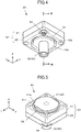
- FIG. 4 is a perspective external appearance view illustrating a configuration example of the inspection jig support tool 20 in the present embodiment and is an external appearance view as viewed up from an obliquely lower side.
- FIG. 5 is a perspective external appearance view illustrating the configuration example of the inspection jig support tool 20 and is an external appearance view as viewed down from an obliquely upper side.
- FIG. 6 is an exploded view of the inspection jig support tool 20.
- FIG. 7 is a vertical cross-sectional view of the inspection jig support tool 20.
- the inspection jig support tool 20 is a mechanical portion that has a floating structure tolerating relative displacement in a direction intersecting with a supporting direction (a vertical direction in the present embodiment: a Z-axis direction in FIGS. 4 to 7 ) while retaining a supported posture of a supported object.
- the inspection jig support tool 20 has a coupling axis portion 30 to be coupled with a supported object (in the present embodiment, the inspection head body 70), an annular coil spring 50, and a base portion 40 in which the annular coil spring 50 is built and that supports the coupling axis portion 30.
- FIG. 8 is a vertical cross-sectional view of the coupling axis portion 30.
- the coupling axis portion 30 is a structure body having plural flange-shaped extended portions around a shaft from which the supported object is suspended.
- the coupling axis portion 30 has a first friction reduction ring 34, a second friction reduction ring 35, and an axis-side fitting portion 39.
- the axis-side fitting portion 39 has a mount shaft 31, a connection shaft 32, and a slide washer 33.
- the axis-side fitting portion 39 is fitted in the base portion 40 and the annular coil spring 50.
- a lower end portion of the mount shaft 31 and an upper end portion of the connection shaft 32 are coupled together by screwing, press-fitting, or the like.
- the slide washer 33 is positioned such that it is held between the mount shaft 31 and the connection shaft 32.
- the slide washer 33 is a flange portion in the axis-side fitting portion 39 and is a circularly annular metal plate, for example.
- the slide washer 33 protrudes outward in a radial direction from an outer peripheral surface of the axis-side fitting portion 39 and touches an inner peripheral surface of the annular coil spring 50.
- the mount shaft 31 is a part of the axis-side fitting portion 39, the part being positioned relatively high in the present embodiment, and has a flange-shaped first extended portion 31e in an outer edge of an upper end portion thereof.
- the first friction reduction ring 34 is attached to an outer edge lower surface of the first extended portion 31e.
- the first friction reduction ring 34 is made of a material that can reduce the friction coefficient compared to a case where the mount shaft 31 directly contacts with the base portion 40 by the first extended portion 31e.
- the first friction reduction ring 34 is realized with a washer formed of a synthetic resin or metal.
- connection shaft 32 is a part of the axis-side fitting portion 39, the part being positioned relatively low in the present embodiment, and has a flange-shaped second extended portion 32e in a position close to the upper end portion.
- the second friction reduction ring 35 similar to the first friction reduction ring 34 is attached to an outer edge upper surface of the second extended portion 32e.
- FIG. 9 is a vertical cross-sectional view of the base portion 40.
- the base portion 40 is a member retaining the coupling axis portion 30 such that it is capable of being displaced in a radial direction of an axis and in an axial rotation direction.
- the base portion 40 is a member retaining the coupling axis portion 30 in a displaceable manner such that even when the axis of the coupling axis portion 30 is moved in an intersecting direction of the axis (the radial direction, in other words, an XY plane direction), a parallel or generally parallel state is maintained between the axis that is not yet moved and the axis that is already moved.
- the base portion 40 is a member retaining the coupling axis portion 30 in a displaceable manner such that the coupling axis portion 30 can be axially rotated.
- the base portion 40 has a first part 41 and a second part 42 that are coupled together by coupling screws 49 while abutting with each other in the vertical direction.
- the first part 41 and the second part 42 have, in respective central portions, hole-side fitting portions 46 through which the axis-side fitting portion 39 of the coupling axis portion 30 is inserted and in which the axis-side fitting portion 39 is fitted with a gap.
- the first part 41 has, on an upper surface side, a first recess portion 41a that is formed to be recessed downward to form a flat circular shape in a plane (an XY plane in FIG. 9 ) orthogonal to the supporting direction of the supported object, when viewed from above.
- the first extended portion 31e and the first friction reduction ring 34 of the coupling axis portion 30 are fitted with a gap such that the first friction reduction ring 34 touches a bottom surface of this first recess portion 41a.
- the first recess portion 41a functions as a support portion supporting the first extended portion 31e and the first friction reduction ring 34 of the coupling axis portion 30 such that those are capable of slide movement along a plane (an XY place in FIG. 9 ) orthogonal to the supporting direction of the supported object.
- the top view radius of the first recess portion 41a is set larger than the top view radii of the first extended portion 31e and the first friction reduction ring 34 of the coupling axis portion 30.
- an inner peripheral side surface of the first recess portion 41a functions as a restriction portion 41s that the outer peripheral surface of the axis-side fitting portion 39 (in the present embodiment, an outer peripheral surface of the first friction reduction ring 34) touches.
- the second part 42 has, on a lower surface side, a second recess portion 42a that is formed to be recessed upward to form a flat circular shape in a plane (an XY plane in FIG. 9 ) orthogonal to the supporting direction of the supported object, when viewed from below.
- the second extended portion 32e and the second friction reduction ring 35 of the coupling axis portion 30 are fitted with a gap such that the second friction reduction ring 35 touches a surface on a lower side as a ceiling of a recess portion of this second recess portion 42a.
- the second recess portion 42a functions as a support portion supporting the second extended portion 32e and the second friction reduction ring 35 of the coupling axis portion 30 such that those are capable of slide movement along a plane (an XY place in FIG. 9 ) orthogonal to the supporting direction of the supported object.
- the bottom view radius of the second recess portion 42a is set larger than the bottom view radii of the second extended portion 32e and the second friction reduction ring 35 of the coupling axis portion 30.
- an inner peripheral side surface of the second recess portion 42a functions as a restriction portion 42s that the outer peripheral surface of the axis-side fitting portion 39 (in the present embodiment, an outer peripheral surface of the second friction reduction ring 35) touches.
- an inner peripheral surface of the first recess portion 41a, an insertion hole 43, and an inner peripheral surface of the second recess portion 42a become the hole-side fitting portions 46 that fit the axis-side fitting portion 39 with a gap.
- the first recess portion 41a and the second recess portion 42a support the coupling axis portion 30 such that it is capable of sliding in a direction parallel with an XY plane (the radial direction) and restricts the coupling axis portion 30 such that it is not displaced in an axis direction of the coupling axis portion 30, by both of the first recess portion 41a and the second recess portion 42a.
- the hole-side fitting portions 46 are held between the two extended portions of the coupling axis portion 30, and movement of the coupling axis portion 30 in the axis direction is thereby restricted.
- the first part 41 has, on a lower surface side, a first circularly annular recess portion 41b that is formed to be recessed upward while forming a circularly annular shape so as to maintain an edge of the insertion hole 43 through whose center the coupling axis portion 30 is inserted, when viewed from below.
- a connection portion between an inside surface of the first circularly annular recess portion 41b and a surface on a lower side as a ceiling of a recess portion of the first circularly annular recess portion 41b forms a slant face and a curved surface with a greater curvature than an outer periphery of the annular coil spring 50.
- the second part 42 has, on an upper surface side, a second circularly annular recess portion 42b that is formed to be recessed downward while forming a circularly annular shape so as to maintain an edge of the insertion hole 43 through whose center the coupling axis portion 30 is inserted, when viewed from below.
- a connection portion between an inside surface of the second circularly annular recess portion 42b and a bottom surface forms a slant face and a curved surface with a greater curvature than the outer periphery of the annular coil spring 50.
- the first part 41 and the second part 42 are combined together, the first circularly annular recess portion 41b and the second circularly annular recess portion 42b abut each other, and a space is thereby formed.
- This space functions as a spring retaining portion 47 that retains the annular coil spring 50 while tolerating deformation in an outward direction of an annular shape (deformation in a radius enlarging direction) but restraining deformation in an inward direction of the annular shape in a restored state (deformation in a radius shrinking direction).
- the spring retaining portion 47 retains the annular coil spring 50 such that it is capable of deforming in the radius enlarging direction to a predetermined maximum tolerated deformation amount.
- the first part 41 and the second part 42 are combined together, and an annular groove portion 48 is thereby formed in an inner peripheral surface of the spring retaining portion 47.
- the slide washer 33 (flange portion) touches the inner peripheral surface of the annular coil spring 50 via this annular groove portion 48.
- the annular coil spring 50 is a circularly annular member that is a coil spring configured in an annular shape.
- the annular coil spring 50 can be made by bending an extension coil spring in a circularly annular shape and connecting both ends together.
- An inner diameter of the annular coil spring 50 is set to agree with a diameter of an inside inner surface of the space of the spring retaining portion 47, and an annular inner surface of the annular coil spring 50 contacts with the inside inner surface of the space of the spring retaining portion 47.
- An outer diameter of an annular shape of the annular coil spring 50 is set smaller than a diameter of an outside inner surface of the space of the spring retaining portion 47. A clearance between both of those is set to become larger than a tolerance amount for relative displacement of the coupling axis portion 30 towards the base portion 40.
- An outer diameter of a coil of the annular coil spring 50 (corresponding to an outer diameter in a Z-axis direction in FIG. 9 ) is set smaller than a thickness of the space of the spring retaining portion 47 in a perpendicular direction (the Z-axis direction in FIG. 9 ).
- the annular coil spring 50 In a no-load state for the annular coil spring 50 as a state where a supported object is not coupled with the inspection jig support tool 20, the annular coil spring 50 is retained along the inside inner surface of the space of the spring retaining portion 47 in a state where slight tension is generated.
- the annular coil spring 50 has a fastening force by which the axis of the coupling axis portion 30 is capable of returning to a reference position in a no-load condition. Because the slide washer 33 touches an inner periphery of the annular shape of the annular coil spring 50, for a central axis of the slide washer 33 (the same as the axis of the shaft of the coupling axis portion 30), a position on a central axis or a generally central axis of the annular shape of the annular coil spring 50 becomes the reference position.
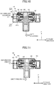
- FIG. 10 and FIG. 11 are diagrams for explaining an action implemented by the inspection jig support tool 20.
- FIG. 10 illustrates a state where a factor of displacement of the coupling axis portion 30 from the reference position occurs.
- Force of displacement mentioned here denotes a state where position deviation between the connector on the inspected side and the inspection jig occurs, in the present embodiment. This position deviation amount is absorbed by a shift (displacement) of the coupling axis portion 30 towards the base portion 40.
- the coupling axis portion 30 is displaced in a left direction in FIG. 10
- a left side portion in FIG. 10 in an annular-shape inside surface of the annular coil spring 50 is pushed by the slide washer 33 (an acting force F1 in FIG. 10 ), and the annular coil spring 50 deforms to extend in the left direction in FIG. 10 .
- a diameter of the coil spring configuring the annular coil spring 50 is smaller than a height of the space of the spring retaining portion 47 in the vertical direction.
- FIG. 10 illustrates a state where the annular coil spring 50 moves to the upper side and contacts with an upper side of the space of the spring retaining portion 47. Because the annular coil spring 50 is pushed by the slide washer 33, the annular coil spring 50 is in a state of contacting with the slide washer 33 also. Because the annular coil spring 50 is deformed in a state where it contacts with the upper side or a lower side of the space of the spring retaining portion 47 and the slide washer 33, although being in a deformed shape, the deformed shape is in a stable state. This also means that a restoring force of the annular coil spring 50 is stably acting.
- FIG. 11 illustrates a circumstance in which the factor of displacement has already been removed.
- the slide washer 33 is urged in a right direction in FIG. 11 by the restoring force of the annular coil spring 50 (an acting force F2 in FIG. 11 ), and the coupling axis portion 30 is returned to the reference position.
- the coupling axis portion 30 reaches the reference position, because the annular coil spring 50 returns to an original annular shape, and the restoring force also stops acting.
- a support tool 63 acts to support the inspection head body 70 such that it is capable of being displaced in a predetermined two-dimensional displaceable range and in a predetermined rotatable angle range.
- the support tool 63 has a first inspection jig support tool 20R, a second inspection jig support tool 20L, and the jig base 60.
- the first inspection jig support tool 20R and the second inspection jig support tool 20L are the inspection jig support tools 20.
- the first inspection jig support tool 20 (20R) and the second inspection jig support tool 20 (20L) are arranged by the jig base 60 such that their respective supporting directions become parallel with the axis of the coupling axis portion 30.
- annular coil spring 50 gets away to a lower side than a position illustrated in FIG. 10 and the annular coil spring 50 becomes a state of being pressed to the bottom surface of the second circularly annular recess portion 42b. Even in such a state, because the restoring force urges the slide washer 33, the coupling axis portion 30 can similarly be returned to the reference position.
- FIG. 12 is a diagram for explaining tolerance for deviation of the inspection head body 70 in an axial rotation direction, the tolerance being realized by the two inspection jig support tools 20.
- Both end portions of the inspection head body 70 are respectively supported by the coupling axis portions 30.
- rotation ⁇ around a perpendicular axis (the Z-axis in FIG. 12 ) (rotation around the perpendicular axis as viewed from the inspection head body 70) occurs to the inspection head body 70 when the probe support portion 74 is connected with the connector on the inspected side
- the two coupling axis portions 30 are displaced in mutually opposite directions around the perpendicular axis direction along a horizontal plane (a direction parallel with an XY plane in FIG. 12 ), and deviation due to the rotation ⁇ is thereby tolerated.
- connection for an inspection is released, because the two inspection jig support tools 20 cause an action for returning the respective coupling axis portions 30 to the reference positions, deviation due to the rotation ⁇ is also removed.
- the inspection jig support tools 20 of the connector inspection jig 10 of the present embodiment can tolerate position deviation between the connector inspection jig 10 and the connector on the inspected side and can also inhibit a change in relative positions of both of those, the change accompanying the tolerance for the position deviation.
- a position is automatically adjusted such that connection can be made in an appropriate position.
- the connector inspection jig 10 automatically returns to an original condition.
- the probe support portion 74 of the connector inspection jig 10 is hardly inclined. Consequently, the possibility is low that the probes 75 installed in the jig obliquely contact with the electrodes of the connector on the inspected side, and the possibility can be lowered that the lives of the probes 75 are shortened by causing an unnecessary lateral load to act on the probes 75.
- annular coil spring 50 is employed as an element for applying the restoring force to the displaced coupling axis portion 30, responsiveness to displacement and durability are excellent compared to a case where an O-ring formed of a resin is used.
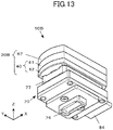
- FIG. 13 is a perspective external appearance view illustrating a configuration example of a connector inspection jig 10B in the second embodiment and is an external appearance view as viewed up from an obliquely lower side.
- FIG. 14 is a perspective external appearance view illustrating the configuration example of the connector inspection jig 10B and is an external appearance view as viewed down from an obliquely upper side.
- FIG. 15 is an exploded view of an inspection jig support tool 20B.
- the two inspection jig support tools 20 are individually prepared as separate bodies and are connected by the jig base 60 (see FIG. 1 to FIG. 3 ), but the connector inspection jig 10B of the second embodiment is different in the point that two inspection jig support tools 20B share the base portion 40 and are integrally configured.
- the present embodiment is different from the first embodiment in the point that the coupling axis portions 30 of the two inspection jig support tools 20 are caused to become a coupled state by a connection piece 66 and the two coupling axis portions 30 are configured to integrally perform relative displacement towards the base portion 40.
- the connector inspection jig 10B has a cover portion 67 that covers the connection piece 66.
- the first embodiment has a configuration in which a conductor electrically connecting the inspection head body 70 and the inspection device body passes through a middle portion between the two inspection jig support tools 20, but the present embodiment is different in the point that an output connector 84 is attached to a side surface of the inspection head body 70 and connection is made with the inspection device body via the output connector 84.
- FIG. 16 is an exploded view of a connector inspection jig 10C in the present embodiment.
- inspection jig support tools 20C included in the connector inspection jig 10C of the present embodiment are different in configuration from those of the first embodiment.
- the other elements than those are similar to the first embodiment.
- FIG. 17 is a perspective external appearance view illustrating a configuration example of the inspection jig support tool 20C in the present embodiment and is an external appearance view as viewed up from an obliquely lower side.
- FIG. 18 is a perspective external appearance view illustrating the configuration example of the inspection jig support tool 20C and is an external appearance view as viewed down from an obliquely upper side.
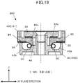
- connection shaft 32C of the present embodiment serves as both of the second part 42 of the base portion 40 in the first embodiment and the connection shaft 32 in the first embodiment.
- a base portion 40C of the present embodiment is configured with one component that corresponds to the first part 41 of the first embodiment and has a stepped recess portion 85 in its lower surface.
- the stepped recess portion 85 has a slant portion 85s around the insertion hole 43.
- a surface that is on the outside of the slant portion 85s and on the inside of the second friction reduction ring 35 in a surface on a lower side as a ceiling of a recess portion of the stepped recess portion 85 becomes continuous with a lower surface of the attached second friction reduction ring 35 and forms a flat surface to an outer periphery of the base portion 40C.
- the surface corresponds to the first circularly annular recess portion 41b of the first embodiment. In other words, the surface forms a surface that an upper surface of the annular coil spring 50 touches.
- connection shaft 32C of the present embodiment is in sliding contact with the surface on the lower side as the ceiling of the recess portion of the stepped recess portion 85, the second friction reduction ring 35 is attached to the surface on the lower side.
- connection shaft 32C of the present embodiment serves as both of the second part 42 of the base portion 40 in the first embodiment and the connection shaft 32 in the first embodiment, the second circularly annular recess portion 42b is formed to be recessed in an upper surface of the connection shaft 32C of the present embodiment.
- a limit of relative displacement of the coupling axis portion 30 is defined by a clearance between an inner peripheral surface of the insertion hole 43 made at a center of the base portion 40 and the connection shaft 32C.
- the inspection jig support tool 20C of the present embodiment can reduce the number of components compared to that of the first embodiment, cost reduction and size reduction can be intended compared to the first embodiment while similar actions and effects are realized.
- the connector inspection jig 10 includes the support tool 63 and the support tool 63 has the two inspection jig support tools 20 (the first inspection jig support tool 20R and the second inspection jig support tool 20L) (see FIG. 1 and FIG. 2 ).
- the support tool 63 may have three or more inspection jig support tools 20.
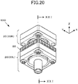
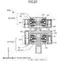
- a configuration is raised, as an example, in which the two inspection jig support tools 20 (the first inspection jig support tool 20R and the second inspection jig support tool 20L) are plurally arranged in a direction intersecting with the axis direction of the coupling axis portion 30; however, the arrangement relationship between the two inspection jig support tools 20 (the first inspection jig support tool 20R and the second inspection jig support tool 20L) is not limited to this example. For example, as illustrated in FIG. 20 and FIG.
- a linking part 88 is fixed to the first part 41 of one of the two inspection jig support tools 20 (20R and 20L), the linking part 88 is connected with the connection shaft 32 of the coupling axis portion 30 of the other, and an integral support tool 63D may thereby be formed in which the inspection jig support tools 20 are multiply connected in the axis direction of the coupling axis portion 30.
- the inspection jig support tools 20 of the first embodiment are capable of being replaced by the support tool 63D. By replacement, an advantage of tolerating larger position deviation can be obtained.
- plural inspection jig support tools 20 (20R and 20L) are linked together such that the axis directions of the coupling axis portions 30 become the same direction; however, a configuration is possible in which the integral support tool 63 is formed by linking those such that the axis directions of the coupling axis portions 30 become different directions (for example, to be orthogonal).
- the connector inspection jig 10 is described as being connected with an inspection target from above; however, the connector inspection jig 10 may be used in a form of being connected with an inspection target from below or may be used in a form of being connected from a lateral side.
- a first aspect of the present disclosure provides an inspection jig support tool including: a coupling axis portion having an axis-side fitting portion and being coupled with an inspection head body; an annular coil spring being arranged in an outer periphery of the axis-side fitting portion; and a base portion retaining the coupling axis portion such that the coupling axis portion is capable of being displaced in a radial direction of an axis and in an axial rotation direction, in which the base portion has: a spring retaining portion retaining the annular coil spring while tolerating deformation of the annular coil spring in a radius enlarging direction; and a hole-side fitting portion being fitted on the axis-side fitting portion with a gap.
- the coupling axis portion coupled with the inspection head body is retained such that displacement in the radial direction of the axis and in the axial rotation direction towards the base portion is possible. Furthermore, as for the coupling axis portion, the axis-side fitting portion is fitted in the hole-side fitting portion with a gap. Consequently, even when mounting positions of connectors on the inspected side are non-uniform, the coupling axis portion is displaced in the radial direction of the axis and in the axial rotation direction towards the base portion, and the inspection head body can thereby quickly move to an appropriate connection position for the connector on the inspected side. Thus, tolerance for and responsiveness to position deviation are excellent.
- the annular coil spring may have a fastening force by which the axis of the coupling axis portion is capable of returning to a reference position in a no-load condition.
- the axis-side fitting portion may have a flange portion that protrudes outward in the radial direction from an outer peripheral surface and touches an inner peripheral surface of the annular coil spring, and the hole-side fitting portion may have a restriction portion that the outer peripheral surface touches in a case where displacement of the coupling axis portion in the radial direction reaches a predetermined maximum tolerated displacement amount.
- the flange portion protrudes outward in the radial direction from the outer peripheral surface of the axis-side fitting portion and touches the inner peripheral surface of the annular coil spring. Because the outer peripheral surface of the axis-side fitting portion touches the restriction portion in a case where displacement of the coupling axis portion in the radial direction reaches the predetermined maximum tolerated displacement amount, the restriction portion can restricts displacement of the coupling axis portion.
- the spring retaining portion may retain the annular coil spring such that the annular coil spring is capable of deforming in the radius enlarging direction to a predetermined maximum tolerated deformation amount, and the maximum tolerated displacement amount may be smaller than the maximum tolerated deformation amount.
- the spring retaining portion may have an annular groove portion, and the flange portion may touch the inner peripheral surface of the annular coil spring via the annular groove portion.
- the axis-side fitting portion may have two extended portions and may hold the hole-side fitting portion between the two extended portions.
- the hole-side fitting portion is held between the two extended portions of the coupling axis portion, and movement of the coupling axis portion in the axis direction is thereby restricted in the base portion.
- a second aspect provides a support tool including a first inspection jig support tool and a second inspection jig support tool according to the first aspect, in which the first inspection jig support tool and the second inspection jig support tool are arranged while the coupling axis portion of the first inspection jig support tool and the coupling axis portion of the second inspection jig support tool are in parallel with each other and the first inspection jig support tool and the second inspection jig support tool support the inspection head body such that the inspection head body is capable of being displaced in a predetermined range.
- the support tool may further include a jig base supporting the inspection head body, in which the first inspection jig support tool may support one end side of the jig base and the second inspection jig support tool may support another end side of the jig base.
- a third aspect provides an inspection jig including: the inspection head body; and the support tool according to the second aspect that supports the inspection head body.
- a fourth aspect provides an inspection jig including: the inspection head body; and the support tool according to the second aspect that supports the inspection head body, in which in the inspection head body, plural probes to contact with an inspected object protrude on an inspection surface side, electrical wires of the probes are drawn out from a back surface on an opposite side to the inspection surface, and the jig base supports the inspection head body in a central portion.
- a fifth aspect provides a support tool including a first inspection jig support tool and a second inspection jig support tool according to the first aspect, in which the base portion of the first inspection jig support tool is coupled with the coupling axis portion of the second inspection jig support tool.
- the two inspection jig support tools are configured as an integral support tool, and the inspection head body can thereby be supported so as to be capable of being displaced in a predetermined range.
Landscapes
- Physics & Mathematics (AREA)
- General Physics & Mathematics (AREA)
- Engineering & Computer Science (AREA)
- Computer Hardware Design (AREA)
- Microelectronics & Electronic Packaging (AREA)
- General Engineering & Computer Science (AREA)
- Environmental & Geological Engineering (AREA)
- Measuring Leads Or Probes (AREA)
- Manufacturing Of Electrical Connectors (AREA)
- Tests Of Electronic Circuits (AREA)
Abstract
Description
- The present invention relates to an inspection jig support tool and so forth.
- An electronic circuit substrate is installed in an electronic apparatus, and a connection terminal referred to as connector is installed in the substrate for connection with another substrate, an external apparatus, or the like. As one of inspection procedures in a manufacturing process of an electronic apparatus, there is a procedure in which a connector inspection jig of an inspection device is connected with the connector and an inspection is conducted.
- For example, Patent Literature 1 discloses a technique of a connector inspection jig that improves visibility in performing work for position alignment between a connector including probes on an inspected side and a connector on a jig side and that has few components to be expendables. Patent Literature 2 discloses a connector inspection jig that facilitates connection work. Patent Literature 3 discloses a compliance mechanism that facilitates position alignment between a connector on an inspected side and a probe holder.
-
- Patent Literature 1:
JP-A-2004-273192 - Patent Literature 2:
JP-A-2005-283218 - Patent Literature 3:
JP-A-7-111176 - In inspecting a substrate, the substrate is fixed to a predetermined position in a predetermined posture. However, viewing the position of each electrode of a connector mounted on the substrate, in an inspection, each electrode is not necessarily fixed to strictly the same position. Consequently, an inspection device is desired to have high tolerance for position deviation.
- The number of electrodes of a connector and arrangement intervals have been adapted to achieve finer features to meet a demand for size reduction of an electronic apparatus. Thus, in inspecting the substrate, highly precise position alignment between a connector on an inspected side and an inspection jig is requested. In addition, because it is desired to shorten a time needed for an inspection, shortening of a time for connection of the inspection jig towards the connector is requested. Consequently, high responsiveness to position deviation is desired while high tolerance for position deviation is realized.
- Although a technique of Patent Literature 1 can improve visibility in position alignment, Patent Literature 1 does not disclose a technique for improving precision of mechanical position alignment itself. Patent Literature 2 does not disclose a technique for improving precision of mechanical position alignment itself either.
- A compliance mechanism disclosed in Patent Literature 3 can realize a certain degree of tolerance for position deviation. However, high responsiveness to position deviation cannot be realized. Although a compliance mechanism as disclosed in Patent Literature 3 tolerates position deviation in two orthogonal directions, neither tolerance nor responsiveness can be considered to be sufficient about position deviation in a direction oblique to both of the two directions. For a reason of a structure of the compliance mechanism, for example, a probe holder that can be considered to be an inspection head may slightly be inclined towards a connector on an inspected side. When the probe holder is inclined, probes obliquely contact with electrodes of the connector on the inspected side, and a lateral load acts on the probes. As a result, a problem possibly occurs that the lives of the probes are shortened.
- One example of objects of the invention is to improve tolerance for and responsiveness to position deviation between a contacted side and a contacting side in a contact.
- A first aspect of the invention provides an inspection jig support tool including: a coupling axis portion having an axis-side fitting portion and being coupled with an inspection head body; an annular coil spring being arranged in an outer periphery of the axis-side fitting portion; and a base portion retaining the coupling axis portion such that the coupling axis portion is capable of being displaced in a radial direction of an axis and in an axial rotation direction, in which the base portion has: a spring retaining portion retaining the annular coil spring while tolerating deformation of the annular coil spring in a radius enlarging direction; and a hole-side fitting portion being fitted on the axis-side fitting portion with a gap.
- A second aspect provides a support tool including a first inspection jig support tool and a second inspection jig support tool according to the first aspect, in which the first inspection jig support tool and the second inspection jig support tool are arranged while the coupling axis portion of the first inspection jig support tool and the coupling axis portion of the second inspection jig support tool are in parallel with each other and the first inspection jig support tool and the second inspection jig support tool support the inspection head body such that the inspection head body is capable of being displaced in a predetermined range.
- A third aspect provides an inspection jig including: the inspection head body; and the support tool according to the second aspect that supports the inspection head body.
- A fourth aspect provides an inspection jig including: the inspection head body; and the support tool according to the second aspect that supports the inspection head body, in which in the inspection head body, plural probes to contact with an inspected object protrude on an inspection surface side, electrical wires of the probes are drawn out from a back surface on an opposite side to the inspection surface, and the jig base supports the inspection head body in a central portion.
- A fifth aspect provides a support tool including a first inspection jig support tool and a second inspection jig support tool according to the first aspect, in which the base portion of the first inspection jig support tool is coupled with the coupling axis portion of the second inspection jig support tool.
- In aspects of the invention, a coupling axis portion coupled with an inspection head body is retained such that displacement in a radial direction of an axis and in an axial rotation direction towards a base portion is possible. Furthermore, as for the coupling axis portion, an axis-side fitting portion is fitted in a hole-side fitting portion with a gap. Consequently, even when mounting positions of connectors on an inspected side are non-uniform, the coupling axis portion is displaced in the radial direction of the axis and in the axial rotation direction towards the base portion, and the inspection head body can thereby quickly move to an appropriate connection position for the connector on the inspected side. Thus, tolerance for and responsiveness to position deviation are excellent.
-
-
FIG. 1 is a perspective external appearance view illustrating a configuration example of a connector inspection jig in a first embodiment. -
FIG. 2 is a perspective external appearance view illustrating the configuration example of the connector inspection jig in the first embodiment. -
FIG. 3 is an exploded view of the connector inspection jig in the first embodiment. -
FIG. 4 is a perspective external appearance view illustrating a configuration example of an inspection jig support tool in the first embodiment. -
FIG. 5 is a perspective external appearance view illustrating the configuration example of the inspection jig support tool in the first embodiment. -
FIG. 6 is an exploded view of the inspection jig support tool in the first embodiment. -
FIG. 7 is a vertical cross-sectional view of the inspection jig support tool in the first embodiment. -
FIG. 8 is a vertical cross-sectional view of a coupling axis portion in the first embodiment. -
FIG. 9 is a vertical cross-sectional view of a base portion in the first embodiment. -
FIG. 10 is a diagram for explaining an action implemented by the inspection jig support tool. -
FIG. 11 is a diagram for explaining the action implemented by the inspection jig support tool. -
FIG. 12 is a diagram for explaining tolerance for deviation of an inspection head body in an axial rotation direction, the tolerance being realized by two inspection jig support tools. -
FIG. 13 is a perspective external appearance view illustrating a configuration example of a connector inspection jig in a second embodiment. -
FIG. 14 is a perspective external appearance view illustrating the configuration example of the connector inspection jig in the second embodiment. -
FIG. 15 is an exploded view of an inspection jig support tool in the second embodiment. -
FIG. 16 is an exploded view of a connector inspection jig in a third embodiment. -
FIG. 17 is a perspective external appearance view illustrating a configuration example of an inspection jig support tool in the third embodiment. -
FIG. 18 is a perspective external appearance view illustrating the configuration example of the inspection jig support tool in the third embodiment. -
FIG. 19 is a vertical cross-sectional view of the inspection jig support tool in the third embodiment. -
FIG. 20 is a perspective external appearance view illustrating a modification example of an inspection jig support tool. -
FIG. 21 is a vertical cross-sectional view illustrating the modification example of an inspection jig support tool. - Examples of embodiments will be described; however, forms to which the invention is applicable are not limited to the following embodiments.
-
FIG. 1 is a perspective external appearance view illustrating a configuration example of aconnector inspection jig 10 in a first embodiment and is an external appearance view as viewed up from an obliquely lower side. -
FIG. 2 is a perspective external appearance view illustrating the configuration example of theconnector inspection jig 10 and is an external appearance view as viewed down from an obliquely upper side. -
FIG. 3 is an exploded view of theconnector inspection jig 10. - The
connector inspection jig 10 in the present embodiment is a jig for connectingprobes 75 with a substrate connector (a connector on an inspected side) mounted on a substrate as an inspection target by moving like descending from above from a Z-axis positive direction to a Z-axis negative direction that are illustrated inFIGS. 1 to 3 . Theprobes 75 include signal measurement probes and grounding probes. - The
connector inspection jig 10 has inspectionjig support tools 20, ajig base 60, aninspection head body 70, andconductor bodies 80. Theconnector inspection jig 10 supports theinspection head body 70 by the inspectionjig support tools 20. - The
jig base 60 fixes two inspectionjig support tools 20 at aspace 61. - The
inspection head body 70 is a supported object that is supported by the two inspectionjig support tools 20. Theinspection head body 70 has aconductor holder 72, aprobe support portion 74, theprobes 75, an electrically conductiveprobe guide plate 76, and ahead base 77. - The
probe support portion 74 is electrically non-conductive and is fixed to a lower end of a central portion of thehead base 77 via theprobe guide plate 76 by a fixingpin 73. Insertion holes for theprobes 75 are made in theprobe support portion 74. Theprobe support portion 74 causes lower portions of theprobes 75 to be inserted through the insertion holes and thereby retains a relative position of each of theprobes 75. A lower end of theprobe 75 becomes a state where it passes through the insertion hole and protrudes on an inspection surface side as a lower surface (a surface on the Z-axis negative direction side) of theprobe support portion 74. In an inspection, theprobe support portion 74 is fitted on the connector on the inspected side and thereby guides theprobes 75 to electrodes of the connector on the inspected side. - The
probe guide plate 76 is electrically conductive, guides theprobes 75 to theprobe support portion 74, and retains relative positions among theprobes 75. Theprobe guide plate 76 functions as a spacer for extending thehead base 77 and adjusts the heights of the grounding probes in theprobes 75. - The
head base 77 has a gap in aninsertion portion 77a at a center, through which theconductor holder 72 is inserted, and thereby retains theconductor holder 72. - The
conductor bodies 80 are electrical wires whose electrically conductive core wires are covered and electrically connect theinspection head body 70 with an inspection device body not illustrated. Theconductor bodies 80 are retained and guided in a state where mutual relative positions are maintained by theconductor holder 72, and lower ends of those are connected with theprobes 75 viacoaxial insulators 82 and acoaxial guide 83. Theconductor body 80 is drawn out from a back surface side of theprobe 75. The back surface side of theprobe 75 is the opposite side to the inspection surface side on which the lower end of theprobe 75 protrudes. It may be considered that theconductor body 80 is drawn out along the longitudinal direction of theprobe 75. - The
coaxial insulator 82 is a member for keeping impedance and serves to keep a coaxial condition between theprobe 75 and theconductor body 80. - The
head base 77 is a straight member in which theconductor holder 72 is inserted through and supported by theinsertion portion 77a at the center. Thehead base 77 is coupled with the inspectionjig support tool 20 by a fixingbolt 78 in each of both end portions. - The two inspection
jig support tools 20 are coupled with an upper surface (a surface on a Z-axis positive direction side) of thehead base 77 via respective floating springs 79. It may be considered that thehead base 77 is suspended from the two inspectionjig support tools 20. -
FIG. 4 is a perspective external appearance view illustrating a configuration example of the inspectionjig support tool 20 in the present embodiment and is an external appearance view as viewed up from an obliquely lower side. -
FIG. 5 is a perspective external appearance view illustrating the configuration example of the inspectionjig support tool 20 and is an external appearance view as viewed down from an obliquely upper side. -
FIG. 6 is an exploded view of the inspectionjig support tool 20. -
FIG. 7 is a vertical cross-sectional view of the inspectionjig support tool 20. - The inspection
jig support tool 20 is a mechanical portion that has a floating structure tolerating relative displacement in a direction intersecting with a supporting direction (a vertical direction in the present embodiment: a Z-axis direction inFIGS. 4 to 7 ) while retaining a supported posture of a supported object. - The inspection
jig support tool 20 has acoupling axis portion 30 to be coupled with a supported object (in the present embodiment, the inspection head body 70), anannular coil spring 50, and abase portion 40 in which theannular coil spring 50 is built and that supports thecoupling axis portion 30. -
FIG. 8 is a vertical cross-sectional view of thecoupling axis portion 30. - The
coupling axis portion 30 is a structure body having plural flange-shaped extended portions around a shaft from which the supported object is suspended. Thecoupling axis portion 30 has a firstfriction reduction ring 34, a secondfriction reduction ring 35, and an axis-sidefitting portion 39. The axis-sidefitting portion 39 has amount shaft 31, aconnection shaft 32, and aslide washer 33. The axis-sidefitting portion 39 is fitted in thebase portion 40 and theannular coil spring 50. - A lower end portion of the
mount shaft 31 and an upper end portion of theconnection shaft 32 are coupled together by screwing, press-fitting, or the like. Theslide washer 33 is positioned such that it is held between themount shaft 31 and theconnection shaft 32. - The
slide washer 33 is a flange portion in the axis-sidefitting portion 39 and is a circularly annular metal plate, for example. Theslide washer 33 protrudes outward in a radial direction from an outer peripheral surface of the axis-sidefitting portion 39 and touches an inner peripheral surface of theannular coil spring 50. - The
mount shaft 31 is a part of the axis-sidefitting portion 39, the part being positioned relatively high in the present embodiment, and has a flange-shaped first extendedportion 31e in an outer edge of an upper end portion thereof. The firstfriction reduction ring 34 is attached to an outer edge lower surface of the firstextended portion 31e. - The first
friction reduction ring 34 is made of a material that can reduce the friction coefficient compared to a case where themount shaft 31 directly contacts with thebase portion 40 by the firstextended portion 31e. For example, the firstfriction reduction ring 34 is realized with a washer formed of a synthetic resin or metal. - The
connection shaft 32 is a part of the axis-sidefitting portion 39, the part being positioned relatively low in the present embodiment, and has a flange-shaped second extendedportion 32e in a position close to the upper end portion. The secondfriction reduction ring 35 similar to the firstfriction reduction ring 34 is attached to an outer edge upper surface of the secondextended portion 32e. -
FIG. 9 is a vertical cross-sectional view of thebase portion 40. - The
base portion 40 is a member retaining thecoupling axis portion 30 such that it is capable of being displaced in a radial direction of an axis and in an axial rotation direction. Thebase portion 40 is a member retaining thecoupling axis portion 30 in a displaceable manner such that even when the axis of thecoupling axis portion 30 is moved in an intersecting direction of the axis (the radial direction, in other words, an XY plane direction), a parallel or generally parallel state is maintained between the axis that is not yet moved and the axis that is already moved. Thebase portion 40 is a member retaining thecoupling axis portion 30 in a displaceable manner such that thecoupling axis portion 30 can be axially rotated. Thebase portion 40 has afirst part 41 and asecond part 42 that are coupled together by couplingscrews 49 while abutting with each other in the vertical direction. - The
first part 41 and thesecond part 42 have, in respective central portions, hole-sidefitting portions 46 through which the axis-sidefitting portion 39 of thecoupling axis portion 30 is inserted and in which the axis-sidefitting portion 39 is fitted with a gap. - The
first part 41 has, on an upper surface side, afirst recess portion 41a that is formed to be recessed downward to form a flat circular shape in a plane (an XY plane inFIG. 9 ) orthogonal to the supporting direction of the supported object, when viewed from above. The firstextended portion 31e and the firstfriction reduction ring 34 of thecoupling axis portion 30 are fitted with a gap such that the firstfriction reduction ring 34 touches a bottom surface of thisfirst recess portion 41a. Thefirst recess portion 41a functions as a support portion supporting the firstextended portion 31e and the firstfriction reduction ring 34 of thecoupling axis portion 30 such that those are capable of slide movement along a plane (an XY place inFIG. 9 ) orthogonal to the supporting direction of the supported object. - The top view radius of the
first recess portion 41a is set larger than the top view radii of the firstextended portion 31e and the firstfriction reduction ring 34 of thecoupling axis portion 30. In a case where the displacement in an intersecting direction intersecting with the axis of thecoupling axis portion 30 fitted in thebase portion 40 reaches a predetermined maximum tolerated displacement amount, an inner peripheral side surface of thefirst recess portion 41a functions as arestriction portion 41s that the outer peripheral surface of the axis-side fitting portion 39 (in the present embodiment, an outer peripheral surface of the first friction reduction ring 34) touches. - The
second part 42 has, on a lower surface side, asecond recess portion 42a that is formed to be recessed upward to form a flat circular shape in a plane (an XY plane inFIG. 9 ) orthogonal to the supporting direction of the supported object, when viewed from below. The secondextended portion 32e and the secondfriction reduction ring 35 of thecoupling axis portion 30 are fitted with a gap such that the secondfriction reduction ring 35 touches a surface on a lower side as a ceiling of a recess portion of thissecond recess portion 42a. Thesecond recess portion 42a functions as a support portion supporting the secondextended portion 32e and the secondfriction reduction ring 35 of thecoupling axis portion 30 such that those are capable of slide movement along a plane (an XY place inFIG. 9 ) orthogonal to the supporting direction of the supported object. - The bottom view radius of the
second recess portion 42a is set larger than the bottom view radii of the secondextended portion 32e and the secondfriction reduction ring 35 of thecoupling axis portion 30. In a case where the displacement in an intersecting direction (that is the radial direction of the axis) intersecting with the axis of thecoupling axis portion 30 fitted in thebase portion 40 reaches a predetermined maximum tolerated displacement amount, an inner peripheral side surface of thesecond recess portion 42a functions as arestriction portion 42s that the outer peripheral surface of the axis-side fitting portion 39 (in the present embodiment, an outer peripheral surface of the second friction reduction ring 35) touches. - Focusing on a fitting relationship between the
coupling axis portion 30 and thebase portion 40, an inner peripheral surface of thefirst recess portion 41a, aninsertion hole 43, and an inner peripheral surface of thesecond recess portion 42a become the hole-sidefitting portions 46 that fit the axis-sidefitting portion 39 with a gap. - The
first recess portion 41a and thesecond recess portion 42a support thecoupling axis portion 30 such that it is capable of sliding in a direction parallel with an XY plane (the radial direction) and restricts thecoupling axis portion 30 such that it is not displaced in an axis direction of thecoupling axis portion 30, by both of thefirst recess portion 41a and thesecond recess portion 42a. In other words, in thebase portion 40, the hole-sidefitting portions 46 are held between the two extended portions of thecoupling axis portion 30, and movement of thecoupling axis portion 30 in the axis direction is thereby restricted. - The
first part 41 has, on a lower surface side, a first circularlyannular recess portion 41b that is formed to be recessed upward while forming a circularly annular shape so as to maintain an edge of theinsertion hole 43 through whose center thecoupling axis portion 30 is inserted, when viewed from below. A connection portion between an inside surface of the first circularlyannular recess portion 41b and a surface on a lower side as a ceiling of a recess portion of the first circularlyannular recess portion 41b forms a slant face and a curved surface with a greater curvature than an outer periphery of theannular coil spring 50. - The
second part 42 has, on an upper surface side, a second circularlyannular recess portion 42b that is formed to be recessed downward while forming a circularly annular shape so as to maintain an edge of theinsertion hole 43 through whose center thecoupling axis portion 30 is inserted, when viewed from below. A connection portion between an inside surface of the second circularlyannular recess portion 42b and a bottom surface forms a slant face and a curved surface with a greater curvature than the outer periphery of theannular coil spring 50. - The
first part 41 and thesecond part 42 are combined together, the first circularlyannular recess portion 41b and the second circularlyannular recess portion 42b abut each other, and a space is thereby formed. This space functions as aspring retaining portion 47 that retains theannular coil spring 50 while tolerating deformation in an outward direction of an annular shape (deformation in a radius enlarging direction) but restraining deformation in an inward direction of the annular shape in a restored state (deformation in a radius shrinking direction). Viewing this in a different way, it may be considered that thespring retaining portion 47 retains theannular coil spring 50 such that it is capable of deforming in the radius enlarging direction to a predetermined maximum tolerated deformation amount. - The
first part 41 and thesecond part 42 are combined together, and anannular groove portion 48 is thereby formed in an inner peripheral surface of thespring retaining portion 47. The slide washer 33 (flange portion) touches the inner peripheral surface of theannular coil spring 50 via thisannular groove portion 48. - The
annular coil spring 50 is a circularly annular member that is a coil spring configured in an annular shape. For example, theannular coil spring 50 can be made by bending an extension coil spring in a circularly annular shape and connecting both ends together. - An inner diameter of the
annular coil spring 50 is set to agree with a diameter of an inside inner surface of the space of thespring retaining portion 47, and an annular inner surface of theannular coil spring 50 contacts with the inside inner surface of the space of thespring retaining portion 47. - An outer diameter of an annular shape of the
annular coil spring 50 is set smaller than a diameter of an outside inner surface of the space of thespring retaining portion 47. A clearance between both of those is set to become larger than a tolerance amount for relative displacement of thecoupling axis portion 30 towards thebase portion 40. - An outer diameter of a coil of the annular coil spring 50 (corresponding to an outer diameter in a Z-axis direction in
FIG. 9 ) is set smaller than a thickness of the space of thespring retaining portion 47 in a perpendicular direction (the Z-axis direction inFIG. 9 ). - In a no-load state for the
annular coil spring 50 as a state where a supported object is not coupled with the inspectionjig support tool 20, theannular coil spring 50 is retained along the inside inner surface of the space of thespring retaining portion 47 in a state where slight tension is generated. - The
annular coil spring 50 has a fastening force by which the axis of thecoupling axis portion 30 is capable of returning to a reference position in a no-load condition. Because theslide washer 33 touches an inner periphery of the annular shape of theannular coil spring 50, for a central axis of the slide washer 33 (the same as the axis of the shaft of the coupling axis portion 30), a position on a central axis or a generally central axis of the annular shape of theannular coil spring 50 becomes the reference position. In the no-load condition in which an external force causing deformation does not act on theannular coil spring 50, the fastening force of theannular coil spring 50 acts on thecoupling axis portion 30 via theslide washer 33, and thecoupling axis portion 30 is restored to the reference position (the state inFIG. 7 ). -
FIG. 10 and FIG. 11 are diagrams for explaining an action implemented by the inspectionjig support tool 20. -
FIG. 10 illustrates a state where a factor of displacement of thecoupling axis portion 30 from the reference position occurs. "Factor of displacement" mentioned here denotes a state where position deviation between the connector on the inspected side and the inspection jig occurs, in the present embodiment. This position deviation amount is absorbed by a shift (displacement) of thecoupling axis portion 30 towards thebase portion 40. - In the example of
FIG. 10 , thecoupling axis portion 30 is displaced in a left direction inFIG. 10 , a left side portion inFIG. 10 in an annular-shape inside surface of theannular coil spring 50 is pushed by the slide washer 33 (an acting force F1 inFIG. 10 ), and theannular coil spring 50 deforms to extend in the left direction inFIG. 10 . Further, a diameter of the coil spring configuring theannular coil spring 50 is smaller than a height of the space of thespring retaining portion 47 in the vertical direction. Thus, a portion deformed in the left direction inFIG. 10 in theannular coil spring 50 deforms to move to an upper side or a lower side inFIG. 10. FIG. 10 illustrates a state where theannular coil spring 50 moves to the upper side and contacts with an upper side of the space of thespring retaining portion 47. Because theannular coil spring 50 is pushed by theslide washer 33, theannular coil spring 50 is in a state of contacting with theslide washer 33 also. Because theannular coil spring 50 is deformed in a state where it contacts with the upper side or a lower side of the space of thespring retaining portion 47 and theslide washer 33, although being in a deformed shape, the deformed shape is in a stable state. This also means that a restoring force of theannular coil spring 50 is stably acting. -
FIG. 11 illustrates a circumstance in which the factor of displacement has already been removed. In the present embodiment, this means thatFIG. 11 illustrates a circumstance in which an inspection is finished, the inspection jig is separated from the connector on the inspected side, and connection is released. When the factor of displacement is removed, theslide washer 33 is urged in a right direction inFIG. 11 by the restoring force of the annular coil spring 50 (an acting force F2 inFIG. 11 ), and thecoupling axis portion 30 is returned to the reference position. When thecoupling axis portion 30 reaches the reference position, because theannular coil spring 50 returns to an original annular shape, and the restoring force also stops acting. - A
support tool 63 acts to support theinspection head body 70 such that it is capable of being displaced in a predetermined two-dimensional displaceable range and in a predetermined rotatable angle range. Thesupport tool 63 has a first inspectionjig support tool 20R, a second inspectionjig support tool 20L, and thejig base 60. The first inspectionjig support tool 20R and the second inspectionjig support tool 20L are the inspectionjig support tools 20. The first inspection jig support tool 20 (20R) and the second inspection jig support tool 20 (20L) are arranged by thejig base 60 such that their respective supporting directions become parallel with the axis of thecoupling axis portion 30. - Depending on an touching positional relationship between the
slide washer 33 and theannular coil spring 50, there may be a case where theannular coil spring 50 gets away to a lower side than a position illustrated inFIG. 10 and theannular coil spring 50 becomes a state of being pressed to the bottom surface of the second circularlyannular recess portion 42b. Even in such a state, because the restoring force urges theslide washer 33, thecoupling axis portion 30 can similarly be returned to the reference position. -
FIG. 12 is a diagram for explaining tolerance for deviation of theinspection head body 70 in an axial rotation direction, the tolerance being realized by the two inspectionjig support tools 20. - Both end portions of the
inspection head body 70 are respectively supported by thecoupling axis portions 30. Thus, even when rotation θ around a perpendicular axis (the Z-axis inFIG. 12 ) (rotation around the perpendicular axis as viewed from the inspection head body 70) occurs to theinspection head body 70 when theprobe support portion 74 is connected with the connector on the inspected side, the twocoupling axis portions 30 are displaced in mutually opposite directions around the perpendicular axis direction along a horizontal plane (a direction parallel with an XY plane inFIG. 12 ), and deviation due to the rotation θ is thereby tolerated. When connection for an inspection is released, because the two inspectionjig support tools 20 cause an action for returning the respectivecoupling axis portions 30 to the reference positions, deviation due to the rotation θ is also removed. - As described above, the inspection
jig support tools 20 of theconnector inspection jig 10 of the present embodiment can tolerate position deviation between theconnector inspection jig 10 and the connector on the inspected side and can also inhibit a change in relative positions of both of those, the change accompanying the tolerance for the position deviation. Thus, in a process in which theconnector inspection jig 10 is connected with the connector on the inspected side, a position is automatically adjusted such that connection can be made in an appropriate position. When the connection between connectors is released after the inspection has been done, theconnector inspection jig 10 automatically returns to an original condition. - In a process in which position deviation is adjusted, the
probe support portion 74 of theconnector inspection jig 10 is hardly inclined. Consequently, the possibility is low that theprobes 75 installed in the jig obliquely contact with the electrodes of the connector on the inspected side, and the possibility can be lowered that the lives of theprobes 75 are shortened by causing an unnecessary lateral load to act on theprobes 75. - Because position deviation is tolerated in each direction in 360 degrees around the perpendicular axis, response capability to position deviation is excellent.
- Because the
annular coil spring 50 is employed as an element for applying the restoring force to the displacedcoupling axis portion 30, responsiveness to displacement and durability are excellent compared to a case where an O-ring formed of a resin is used. - Next, a second embodiment will be described. In the following, a description will mainly be made about differences from the first embodiment, the same reference characters as the first embodiment are given to similar configuration elements to the first embodiment, and descriptions thereof will not be repeated.
-
FIG. 13 is a perspective external appearance view illustrating a configuration example of aconnector inspection jig 10B in the second embodiment and is an external appearance view as viewed up from an obliquely lower side. -
FIG. 14 is a perspective external appearance view illustrating the configuration example of theconnector inspection jig 10B and is an external appearance view as viewed down from an obliquely upper side. -
FIG. 15 is an exploded view of an inspectionjig support tool 20B. - Comparing the present embodiment with the first embodiment, in the first embodiment, the two inspection
jig support tools 20 are individually prepared as separate bodies and are connected by the jig base 60 (seeFIG. 1 to FIG. 3 ), but theconnector inspection jig 10B of the second embodiment is different in the point that two inspectionjig support tools 20B share thebase portion 40 and are integrally configured. - The present embodiment is different from the first embodiment in the point that the
coupling axis portions 30 of the two inspectionjig support tools 20 are caused to become a coupled state by aconnection piece 66 and the twocoupling axis portions 30 are configured to integrally perform relative displacement towards thebase portion 40. Theconnector inspection jig 10B has acover portion 67 that covers theconnection piece 66. - The first embodiment has a configuration in which a conductor electrically connecting the
inspection head body 70 and the inspection device body passes through a middle portion between the two inspectionjig support tools 20, but the present embodiment is different in the point that anoutput connector 84 is attached to a side surface of theinspection head body 70 and connection is made with the inspection device body via theoutput connector 84. - Next, a third embodiment will be described. In the following, a description will mainly be made about differences from the first embodiment, the same reference characters as the first embodiment are given to similar configuration elements to the first embodiment, and descriptions thereof will not be repeated.
-
FIG. 16 is an exploded view of aconnector inspection jig 10C in the present embodiment. - Comparing the present embodiment with the first embodiment, inspection
jig support tools 20C included in theconnector inspection jig 10C of the present embodiment are different in configuration from those of the first embodiment. The other elements than those are similar to the first embodiment. -
FIG. 17 is a perspective external appearance view illustrating a configuration example of the inspectionjig support tool 20C in the present embodiment and is an external appearance view as viewed up from an obliquely lower side. -
FIG. 18 is a perspective external appearance view illustrating the configuration example of the inspectionjig support tool 20C and is an external appearance view as viewed down from an obliquely upper side. - When the inspection
jig support tool 20C of the present embodiment is compared with the inspectionjig support tool 20 of the first embodiment, aconnection shaft 32C of the present embodiment serves as both of thesecond part 42 of thebase portion 40 in the first embodiment and theconnection shaft 32 in the first embodiment. - A
base portion 40C of the present embodiment is configured with one component that corresponds to thefirst part 41 of the first embodiment and has a steppedrecess portion 85 in its lower surface. - The stepped
recess portion 85 has aslant portion 85s around theinsertion hole 43. A surface that is on the outside of theslant portion 85s and on the inside of the secondfriction reduction ring 35 in a surface on a lower side as a ceiling of a recess portion of the steppedrecess portion 85 becomes continuous with a lower surface of the attached secondfriction reduction ring 35 and forms a flat surface to an outer periphery of thebase portion 40C. The surface corresponds to the first circularlyannular recess portion 41b of the first embodiment. In other words, the surface forms a surface that an upper surface of theannular coil spring 50 touches. - Because the
connection shaft 32C of the present embodiment is in sliding contact with the surface on the lower side as the ceiling of the recess portion of the steppedrecess portion 85, the secondfriction reduction ring 35 is attached to the surface on the lower side. - Because the
connection shaft 32C of the present embodiment serves as both of thesecond part 42 of thebase portion 40 in the first embodiment and theconnection shaft 32 in the first embodiment, the second circularlyannular recess portion 42b is formed to be recessed in an upper surface of theconnection shaft 32C of the present embodiment. - In the inspection
jig support tool 20C of the present embodiment, a limit of relative displacement of thecoupling axis portion 30 is defined by a clearance between an inner peripheral surface of theinsertion hole 43 made at a center of thebase portion 40 and theconnection shaft 32C. - The inspection
jig support tool 20C of the present embodiment can reduce the number of components compared to that of the first embodiment, cost reduction and size reduction can be intended compared to the first embodiment while similar actions and effects are realized. - In the above, some embodiments to which the invention is applied are described. However, forms to which the invention is applicable are not limited to the above forms, but appropriate addition, omission, alterations of configuration elements may be conducted.
- For example, in the first embodiment, an example is described where the
connector inspection jig 10 includes thesupport tool 63 and thesupport tool 63 has the two inspection jig support tools 20 (the first inspectionjig support tool 20R and the second inspectionjig support tool 20L) (seeFIG. 1 andFIG. 2 ). However, thesupport tool 63 may have three or more inspectionjig support tools 20. - In the above embodiment, a configuration is raised, as an example, in which the two inspection jig support tools 20 (the first inspection
jig support tool 20R and the second inspectionjig support tool 20L) are plurally arranged in a direction intersecting with the axis direction of thecoupling axis portion 30; however, the arrangement relationship between the two inspection jig support tools 20 (the first inspectionjig support tool 20R and the second inspectionjig support tool 20L) is not limited to this example. For example, as illustrated inFIG. 20 andFIG. 21 , a linkingpart 88 is fixed to thefirst part 41 of one of the two inspection jig support tools 20 (20R and 20L), the linkingpart 88 is connected with theconnection shaft 32 of thecoupling axis portion 30 of the other, and anintegral support tool 63D may thereby be formed in which the inspectionjig support tools 20 are multiply connected in the axis direction of thecoupling axis portion 30. The inspectionjig support tools 20 of the first embodiment are capable of being replaced by thesupport tool 63D. By replacement, an advantage of tolerating larger position deviation can be obtained. - In addition, in the example of
FIG. 20 andFIG. 21 , plural inspection jig support tools 20 (20R and 20L) are linked together such that the axis directions of thecoupling axis portions 30 become the same direction; however, a configuration is possible in which theintegral support tool 63 is formed by linking those such that the axis directions of thecoupling axis portions 30 become different directions (for example, to be orthogonal). - In the above embodiment, the
connector inspection jig 10 is described as being connected with an inspection target from above; however, theconnector inspection jig 10 may be used in a form of being connected with an inspection target from below or may be used in a form of being connected from a lateral side. - The disclosure described above may be summarized as follows.
- A first aspect of the present disclosure provides an inspection jig support tool including: a coupling axis portion having an axis-side fitting portion and being coupled with an inspection head body; an annular coil spring being arranged in an outer periphery of the axis-side fitting portion; and a base portion retaining the coupling axis portion such that the coupling axis portion is capable of being displaced in a radial direction of an axis and in an axial rotation direction, in which the base portion has: a spring retaining portion retaining the annular coil spring while tolerating deformation of the annular coil spring in a radius enlarging direction; and a hole-side fitting portion being fitted on the axis-side fitting portion with a gap.
- In the first aspect, the coupling axis portion coupled with the inspection head body is retained such that displacement in the radial direction of the axis and in the axial rotation direction towards the base portion is possible. Furthermore, as for the coupling axis portion, the axis-side fitting portion is fitted in the hole-side fitting portion with a gap. Consequently, even when mounting positions of connectors on the inspected side are non-uniform, the coupling axis portion is displaced in the radial direction of the axis and in the axial rotation direction towards the base portion, and the inspection head body can thereby quickly move to an appropriate connection position for the connector on the inspected side. Thus, tolerance for and responsiveness to position deviation are excellent.
- The annular coil spring may have a fastening force by which the axis of the coupling axis portion is capable of returning to a reference position in a no-load condition.
- In the no-load condition, the fastening force of the annular coil spring acts, and the coupling axis portion is restored to the reference position.
- The axis-side fitting portion may have a flange portion that protrudes outward in the radial direction from an outer peripheral surface and touches an inner peripheral surface of the annular coil spring, and the hole-side fitting portion may have a restriction portion that the outer peripheral surface touches in a case where displacement of the coupling axis portion in the radial direction reaches a predetermined maximum tolerated displacement amount.
- The flange portion protrudes outward in the radial direction from the outer peripheral surface of the axis-side fitting portion and touches the inner peripheral surface of the annular coil spring. Because the outer peripheral surface of the axis-side fitting portion touches the restriction portion in a case where displacement of the coupling axis portion in the radial direction reaches the predetermined maximum tolerated displacement amount, the restriction portion can restricts displacement of the coupling axis portion.
- The spring retaining portion may retain the annular coil spring such that the annular coil spring is capable of deforming in the radius enlarging direction to a predetermined maximum tolerated deformation amount, and the maximum tolerated displacement amount may be smaller than the maximum tolerated deformation amount.
- The spring retaining portion may have an annular groove portion, and the flange portion may touch the inner peripheral surface of the annular coil spring via the annular groove portion.
- The axis-side fitting portion may have two extended portions and may hold the hole-side fitting portion between the two extended portions.
- The hole-side fitting portion is held between the two extended portions of the coupling axis portion, and movement of the coupling axis portion in the axis direction is thereby restricted in the base portion.
- A second aspect provides a support tool including a first inspection jig support tool and a second inspection jig support tool according to the first aspect, in which the first inspection jig support tool and the second inspection jig support tool are arranged while the coupling axis portion of the first inspection jig support tool and the coupling axis portion of the second inspection jig support tool are in parallel with each other and the first inspection jig support tool and the second inspection jig support tool support the inspection head body such that the inspection head body is capable of being displaced in a predetermined range.
- In the second aspect, tolerance for and responsiveness to position deviation are excellent.
- The support tool may further include a jig base supporting the inspection head body, in which the first inspection jig support tool may support one end side of the jig base and the second inspection jig support tool may support another end side of the jig base.
- A third aspect provides an inspection jig including: the inspection head body; and the support tool according to the second aspect that supports the inspection head body.
- In the third aspect, tolerance for and responsiveness to position deviation are excellent.
- A fourth aspect provides an inspection jig including: the inspection head body; and the support tool according to the second aspect that supports the inspection head body, in which in the inspection head body, plural probes to contact with an inspected object protrude on an inspection surface side, electrical wires of the probes are drawn out from a back surface on an opposite side to the inspection surface, and the jig base supports the inspection head body in a central portion.
- In the fourth aspect, tolerance for and responsiveness to position deviation are excellent.
- A fifth aspect provides a support tool including a first inspection jig support tool and a second inspection jig support tool according to the first aspect, in which the base portion of the first inspection jig support tool is coupled with the coupling axis portion of the second inspection jig support tool.
- In the fifth aspect, tolerance for and responsiveness to position deviation are excellent. In addition, the two inspection jig support tools are configured as an integral support tool, and the inspection head body can thereby be supported so as to be capable of being displaced in a predetermined range.
-
- 10, 10B, 10C
- connector inspection jig
- 20, 20B, 20C
- inspection jig support tool
- 20R
- first inspection jig support tool
- 20L
- second inspection jig support tool
- 30
- coupling axis portion
- 31
- mount shaft
- 31e
- first extended portion
- 32, 32C
- connection shaft
- 32e
- second extended portion
- 33
- slide washer
- 34
- first friction reduction ring
- 35
- second friction reduction ring
- 39
- axis-side fitting portion
- 40, 40C
- base portion
- 41
- first part
- 41a
- first recess portion
- 41b
- first circularly annular recess portion
- 41s
- restriction portion
- 42
- second part
- 42a
- second recess portion
- 42b
- second circularly annular recess portion
- 42s
- restriction portion
- 43
- insertion hole
- 46
- hole-side fitting portion
- 47
- spring retaining portion
- 48
- annular groove portion
- 50
- annular coil spring
- 60
- jig base
- 61
- space
- 63, 63D
- support tool
- 70
- inspection head body
- 74
- probe support portion
- 75
- probe
- 77
- head base
- 80
- conductor body
- 84
- output connector
- 85
- stepped recess portion
- θ
- rotation (rotation around fixed axis)
Claims (11)
- An inspection jig support tool comprising:a coupling axis portion having an axis-side fitting portion and being coupled with an inspection head body;an annular coil spring being arranged in an outer periphery of the axis-side fitting portion; anda base portion retaining the coupling axis portion such that the coupling axis portion is capable of being displaced in a radial direction of an axis and in an axial rotation direction,whereinthe base portion has:a spring retaining portion retaining the annular coil spring while tolerating deformation of the annular coil spring in a radius enlarging direction; anda hole-side fitting portion being fitted on the axis-side fitting portion with a gap.
- The inspection jig support tool according to claim 1, wherein
the annular coil spring has a fastening force by which the axis of the coupling axis portion is capable of returning to a reference position in a no-load condition. - The inspection jig support tool according to claim 2, whereinthe axis-side fitting portion has a flange portion that protrudes outward in the radial direction from an outer peripheral surface and touches an inner peripheral surface of the annular coil spring, andthe hole-side fitting portion has a restriction portion that the outer peripheral surface touches in a case where displacement of the coupling axis portion in the radial direction reaches a predetermined maximum tolerated displacement amount.
- The inspection jig support tool according to claim 3, whereinthe spring retaining portion retains the annular coil spring such that the annular coil spring is capable of deforming in the radius enlarging direction to a predetermined maximum tolerated deformation amount, andthe maximum tolerated displacement amount is smaller than the maximum tolerated deformation amount.
- The inspection jig support tool according to claim 3 or 4, whereinthe spring retaining portion has an annular groove portion, andthe flange portion touches the inner peripheral surface of the annular coil spring via the annular groove portion.
- The inspection jig support tool according to any one of claims 3 to 5, wherein
the axis-side fitting portion has two extended portions and holds the hole-side fitting portion between the two extended portions. - A support tool comprisinga first inspection jig support tool and a second inspection jig support tool according to any one of claims 1 to 6, whereinthe first inspection jig support tool and the second inspection jig support tool are arranged while the coupling axis portion of the first inspection jig support tool and the coupling axis portion of the second inspection jig support tool are in parallel with each other, andthe first inspection jig support tool and the second inspection jig support tool support the inspection head body such that the inspection head body is capable of being displaced in a predetermined range.
- The support tool according to claim 7, further comprisinga jig base supporting the inspection head body, whereinthe first inspection jig support tool supports one end side of the jig base, andthe second inspection jig support tool supports another end side of the jig base.
- An inspection jig comprising:the inspection head body; andthe support tool according to claim 7 or 8 that supports the inspection head body.
- An inspection jig comprising:the inspection head body; andthe support tool according to claim 8 that supports the inspection head body, whereinin the inspection head body, plural probes to contact with an inspected object protrude on an inspection surface side, electrical wires of the probes are drawn out from a back surface on an opposite side to the inspection surface, andthe jig base supports the inspection head body in a central portion.
- A support tool comprisinga first inspection jig support tool and a second inspection jig support tool according to any one of claims 1 to 6, whereinthe base portion of the first inspection jig support tool is coupled with the coupling axis portion of the second inspection jig support tool.
Applications Claiming Priority (2)
| Application Number | Priority Date | Filing Date | Title |
|---|---|---|---|
| JP2018240056 | 2018-12-21 | ||
| PCT/JP2019/047420 WO2020129646A1 (en) | 2018-12-21 | 2019-12-04 | Inspection jig support, support, and inspection jig |
Publications (2)
| Publication Number | Publication Date |
|---|---|
| EP3901637A1 true EP3901637A1 (en) | 2021-10-27 |
| EP3901637A4 EP3901637A4 (en) | 2022-08-17 |
Family
ID=71101688
Family Applications (1)
| Application Number | Title | Priority Date | Filing Date |
|---|---|---|---|
| EP19901202.2A Withdrawn EP3901637A4 (en) | 2018-12-21 | 2019-12-04 | Inspection jig support, support, and inspection jig |
Country Status (7)
| Country | Link |
|---|---|
| US (1) | US20220082585A1 (en) |
| EP (1) | EP3901637A4 (en) |
| JP (1) | JPWO2020129646A1 (en) |
| KR (1) | KR20210104660A (en) |
| CN (1) | CN113015913A (en) |
| TW (1) | TW202033967A (en) |
| WO (1) | WO2020129646A1 (en) |
Families Citing this family (2)
| Publication number | Priority date | Publication date | Assignee | Title |
|---|---|---|---|---|
| CN113945367A (en) * | 2020-06-30 | 2022-01-18 | 三赢科技(深圳)有限公司 | Tensile Test Fixtures and Tensile Testers |
| CN115000762A (en) * | 2022-06-16 | 2022-09-02 | 浙江盛迪科技股份有限公司 | Female butt joint module of row |
Family Cites Families (19)
| Publication number | Priority date | Publication date | Assignee | Title |
|---|---|---|---|---|
| US3312928A (en) * | 1964-07-21 | 1967-04-04 | Pyle National Co | Explosion-proof connector |
| US4355854A (en) * | 1978-11-13 | 1982-10-26 | Williams Robert A | Self-locking means |
| US4850893A (en) * | 1987-05-14 | 1989-07-25 | Williams Robert A | Test probe apparatus |
| US4914061A (en) * | 1987-10-01 | 1990-04-03 | Williams Robert A | Test probe apparatus |
| US4995837A (en) * | 1989-08-30 | 1991-02-26 | Amp Incorporated | Precision test connector |
| JPH0512794U (en) * | 1991-08-02 | 1993-02-19 | 株式会社アドバンテスト | Mechanical floating support parts |
| JPH0618622A (en) * | 1992-07-01 | 1994-01-28 | Mitsubishi Electric Corp | IC test equipment |
| JP2678875B2 (en) | 1993-10-14 | 1997-11-19 | 日本航空電子工業株式会社 | Connector inspection jig |
| US5923180A (en) * | 1997-02-04 | 1999-07-13 | Hewlett-Packard Company | Compliant wafer prober docking adapter |
| JP2004273192A (en) | 2003-03-06 | 2004-09-30 | Yokowo Co Ltd | Tool for inspection of connector |
| JP2005283218A (en) | 2004-03-29 | 2005-10-13 | Eight Kogyo:Kk | Connector inspection jig |
| US7507099B2 (en) * | 2004-10-01 | 2009-03-24 | Teradyne, Inc. | Floating interface linkage |
| JP4465250B2 (en) * | 2004-10-05 | 2010-05-19 | 株式会社精研 | Inspection unit and inspection apparatus using the same |
| JP2008198505A (en) * | 2007-02-14 | 2008-08-28 | Yokowo Co Ltd | Coil spring contact |
| WO2011024295A1 (en) * | 2009-08-28 | 2011-03-03 | 株式会社アドバンテスト | Interface apparatus and semiconductor testing apparatus |
| JP2013100994A (en) * | 2011-11-07 | 2013-05-23 | Nidec-Read Corp | Substrate inspection jig, jig base unit and substrate inspection device |
| JP2015021726A (en) * | 2013-07-16 | 2015-02-02 | 日置電機株式会社 | Probe unit and substrate inspection device |
| KR101897996B1 (en) * | 2014-11-07 | 2018-09-12 | 가부시키가이샤 무라타 세이사쿠쇼 | Probe |
| CN110088632B (en) * | 2016-12-22 | 2021-07-30 | 株式会社村田制作所 | Detector Construction |
-
2019
- 2019-11-20 TW TW108142160A patent/TW202033967A/en unknown
- 2019-12-04 CN CN201980074570.6A patent/CN113015913A/en active Pending
- 2019-12-04 US US17/413,948 patent/US20220082585A1/en not_active Abandoned
- 2019-12-04 WO PCT/JP2019/047420 patent/WO2020129646A1/en not_active Ceased
- 2019-12-04 EP EP19901202.2A patent/EP3901637A4/en not_active Withdrawn
- 2019-12-04 KR KR1020217014204A patent/KR20210104660A/en not_active Withdrawn
- 2019-12-04 JP JP2020561283A patent/JPWO2020129646A1/en active Pending
Also Published As
| Publication number | Publication date |
|---|---|
| CN113015913A (en) | 2021-06-22 |
| JPWO2020129646A1 (en) | 2021-11-04 |
| WO2020129646A1 (en) | 2020-06-25 |
| US20220082585A1 (en) | 2022-03-17 |
| KR20210104660A (en) | 2021-08-25 |
| TW202033967A (en) | 2020-09-16 |
| EP3901637A4 (en) | 2022-08-17 |
Similar Documents
| Publication | Publication Date | Title |
|---|---|---|
| US11226380B2 (en) | Probe structure | |
| EP3156805A1 (en) | Probe pin and electronic device using same | |
| CN106663903A (en) | Coaxial connector with floating mechanism | |
| CN114830452B (en) | Connector device | |
| JP2017146118A (en) | Probe pin and inspection apparatus using the same | |
| US20220082585A1 (en) | Inspection jig support tool, support tool, and inspection jig | |
| KR20210039292A (en) | Electrical contactor, electrical connecting structure and electrical connecting apparatus | |
| KR102196098B1 (en) | Socket Assembly for Testing Electronic Module | |
| KR20200080922A (en) | Contact pin for test socket and test socket comprising the same | |
| CN114616723A (en) | connector device | |
| KR102538245B1 (en) | probe | |
| JP5486760B2 (en) | Contact pin and socket for electrical parts | |
| US12519275B2 (en) | Connector with floating mechanism | |
| JPH07111176A (en) | Connector inspection jig | |
| TW202331266A (en) | Probe capable of improving the inspection accuracy of a connector | |
| US12278443B2 (en) | Contact pin and socket | |
| JP2023174009A (en) | connector | |
| JP2023026039A (en) | Probe and test socket | |
| TW202331267A (en) | Probe capable of improving the inspection accuracy of a connector | |
| CN115699476B (en) | Connector device | |
| US20250383370A1 (en) | Socket | |
| KR20210132709A (en) | Electrical Contacts and Electrical Connections | |
| JP7816951B2 (en) | Contact Probe | |
| US20260081395A1 (en) | Repairable connector | |
| JP2026004698A (en) | connector |
Legal Events
| Date | Code | Title | Description |
|---|---|---|---|
| STAA | Information on the status of an ep patent application or granted ep patent |
Free format text: STATUS: THE INTERNATIONAL PUBLICATION HAS BEEN MADE |
|
| PUAI | Public reference made under article 153(3) epc to a published international application that has entered the european phase |
Free format text: ORIGINAL CODE: 0009012 |
|
| STAA | Information on the status of an ep patent application or granted ep patent |
Free format text: STATUS: REQUEST FOR EXAMINATION WAS MADE |
|
| 17P | Request for examination filed |
Effective date: 20210604 |
|
| AK | Designated contracting states |
Kind code of ref document: A1 Designated state(s): AL AT BE BG CH CY CZ DE DK EE ES FI FR GB GR HR HU IE IS IT LI LT LU LV MC MK MT NL NO PL PT RO RS SE SI SK SM TR |
|
| DAV | Request for validation of the european patent (deleted) | ||
| DAX | Request for extension of the european patent (deleted) | ||
| A4 | Supplementary search report drawn up and despatched |
Effective date: 20220719 |
|
| RIC1 | Information provided on ipc code assigned before grant |
Ipc: G01R 31/28 20060101ALI20220714BHEP Ipc: G01R 31/50 20200101ALI20220714BHEP Ipc: G01R 1/067 20060101ALI20220714BHEP Ipc: G01R 1/06 20060101AFI20220714BHEP |
|
| STAA | Information on the status of an ep patent application or granted ep patent |
Free format text: STATUS: THE APPLICATION HAS BEEN WITHDRAWN |
|
| 18W | Application withdrawn |
Effective date: 20221006 |