EP3901552B1 - Dichtungsanordnung, verfahren zur herstellung einer dichtungsanordnung und anordnung - Google Patents
Dichtungsanordnung, verfahren zur herstellung einer dichtungsanordnung und anordnung Download PDFInfo
- Publication number
- EP3901552B1 EP3901552B1 EP20170989.6A EP20170989A EP3901552B1 EP 3901552 B1 EP3901552 B1 EP 3901552B1 EP 20170989 A EP20170989 A EP 20170989A EP 3901552 B1 EP3901552 B1 EP 3901552B1
- Authority
- EP
- European Patent Office
- Prior art keywords
- gasket
- projection
- heat transfer
- arrangement
- transfer plate
- Prior art date
- Legal status (The legal status is an assumption and is not a legal conclusion. Google has not performed a legal analysis and makes no representation as to the accuracy of the status listed.)
- Active
Links
Images

Classifications
-
- F—MECHANICAL ENGINEERING; LIGHTING; HEATING; WEAPONS; BLASTING
- F28—HEAT EXCHANGE IN GENERAL
- F28F—DETAILS OF HEAT-EXCHANGE AND HEAT-TRANSFER APPARATUS, OF GENERAL APPLICATION
- F28F9/00—Casings; Header boxes; Auxiliary supports for elements; Auxiliary members within casings
- F28F9/02—Header boxes; End plates
- F28F9/0219—Arrangements for sealing end plates into casing or header box; Header box sub-elements
-
- F—MECHANICAL ENGINEERING; LIGHTING; HEATING; WEAPONS; BLASTING
- F28—HEAT EXCHANGE IN GENERAL
- F28F—DETAILS OF HEAT-EXCHANGE AND HEAT-TRANSFER APPARATUS, OF GENERAL APPLICATION
- F28F3/00—Plate-like or laminated elements; Assemblies of plate-like or laminated elements
- F28F3/08—Elements constructed for building-up into stacks, e.g. capable of being taken apart for cleaning
- F28F3/10—Arrangements for sealing the margins
-
- G—PHYSICS
- G06—COMPUTING OR CALCULATING; COUNTING
- G06K—GRAPHICAL DATA READING; PRESENTATION OF DATA; RECORD CARRIERS; HANDLING RECORD CARRIERS
- G06K19/00—Record carriers for use with machines and with at least a part designed to carry digital markings
- G06K19/06—Record carriers for use with machines and with at least a part designed to carry digital markings characterised by the kind of the digital marking, e.g. shape, nature, code
- G06K19/067—Record carriers with conductive marks, printed circuits or semiconductor circuit elements, e.g. credit or identity cards also with resonating or responding marks without active components
- G06K19/07—Record carriers with conductive marks, printed circuits or semiconductor circuit elements, e.g. credit or identity cards also with resonating or responding marks without active components with integrated circuit chips
- G06K19/0723—Record carriers with conductive marks, printed circuits or semiconductor circuit elements, e.g. credit or identity cards also with resonating or responding marks without active components with integrated circuit chips the record carrier comprising an arrangement for non-contact communication, e.g. wireless communication circuits on transponder cards, non-contact smart cards or RFIDs
-
- F—MECHANICAL ENGINEERING; LIGHTING; HEATING; WEAPONS; BLASTING
- F28—HEAT EXCHANGE IN GENERAL
- F28D—HEAT-EXCHANGE APPARATUS, NOT PROVIDED FOR IN ANOTHER SUBCLASS, IN WHICH THE HEAT-EXCHANGE MEDIA DO NOT COME INTO DIRECT CONTACT
- F28D9/00—Heat-exchange apparatus having stationary plate-like or laminated conduit assemblies for both heat-exchange media, the media being in contact with different sides of a conduit wall
- F28D9/0031—Heat-exchange apparatus having stationary plate-like or laminated conduit assemblies for both heat-exchange media, the media being in contact with different sides of a conduit wall the conduits for one heat-exchange medium being formed by paired plates touching each other
- F28D9/0043—Heat-exchange apparatus having stationary plate-like or laminated conduit assemblies for both heat-exchange media, the media being in contact with different sides of a conduit wall the conduits for one heat-exchange medium being formed by paired plates touching each other the plates having openings therein for circulation of at least one heat-exchange medium from one conduit to another
- F28D9/005—Heat-exchange apparatus having stationary plate-like or laminated conduit assemblies for both heat-exchange media, the media being in contact with different sides of a conduit wall the conduits for one heat-exchange medium being formed by paired plates touching each other the plates having openings therein for circulation of at least one heat-exchange medium from one conduit to another the plates having openings therein for both heat-exchange media
-
- F—MECHANICAL ENGINEERING; LIGHTING; HEATING; WEAPONS; BLASTING
- F28—HEAT EXCHANGE IN GENERAL
- F28F—DETAILS OF HEAT-EXCHANGE AND HEAT-TRANSFER APPARATUS, OF GENERAL APPLICATION
- F28F2230/00—Sealing means
Definitions
- the invention relates to a gasket arrangement for a plate heat exchanger, a method of manufacturing such and an assembly comprising such.
- Plate heat exchangers typically consist of two end plates in between which a number of heat transfer plates are arranged in an aligned manner, i.e. in a stack or pack.
- the heat transfer plates of a PHE may be of the same or different types and they may be stacked in different ways. In some PHEs, the heat transfer plates are stacked with the front side and the back side of one heat transfer plate facing the back side and the front side, respectively, of other heat transfer plates, and every other heat transfer plate turned upside down in relation to the rest of the heat transfer plates. Typically, this is referred to as the heat transfer plates being "rotated" in relation to each other.
- the heat transfer plates are stacked with the front side and the back side of one heat transfer plate facing the front side and back side, respectively, of other heat transfer plates, and every other heat transfer plate turned upside down in relation to the rest of the heat transfer plates. Typically, this is referred to as the heat transfer plates being "flipped" in relation to each other.
- the heat transfer plates are typically corrugated so as to comprise ridges extending in an upper plane, and valleys extending in a lower plane.
- gaskets are arranged between the heat transfer plates, more particularly in gasket grooves extending along outer edges and around port holes of the heat transfer plates.
- the gasket grooves may extend in the lower plane and/or in an intermediate plane arranged between the upper and lower planes.
- the intermediate plane could extend halfway between the upper and lower planes, i.e. be a so-called as half-plane.
- the end plates, and therefore the heat transfer plates are pressed towards each other whereby the gaskets seal between the heat transfer plates.
- the gaskets define parallel flow channels between the heat transfer plates, one channel between each pair of heat transfer plates. Two fluids of initially different temperatures can flow through every second channel for transferring heat from one fluid to the other.
- the fluids enter and exit the channels through inlet and outlet ports, respectively, which extend through the PHE and are formed by respective aligned port holes of the heat transfer plates and the gaskets sealing, completely or partly, around the port holes.
- the inlet and outlet ports communicate with inlets and outlets, respectively, of the PHE for feeding the fluids to and from the PHE.
- the gaskets are often marked with information about the gaskets, more particularly information which is common for gaskets of a certain type, such as article number and material of the gaskets.
- the gaskets are not provided with any "dynamic” information, such as batch number, manufacturing date, etc.
- the gasket manufacturer typically provides this "dynamic” information on an easily removable label fastened to the gaskets or the gasket packaging.
- the label is typically separated from the gaskets and lost. This makes it impossible to later trace the gaskets, which is desirable in many situations, for example in connection with claims to be able to find the source of the problem.
- JP-B-4990224 discloses a gasket having a RFID tag embedded in the base of the gasket.
- An object of the present invention is to provide a gasket arrangement for a plate heat exchanger, a method of manufacturing such a gasket arrangement and an assembly comprising such a gasket arrangement, that at least partly solve the issue above.
- the basic concept of the invention is to provide a gasket with an RFID tag for storing information at a location where it does not impair the sealing function of the gasket and where it can be read by means of an external reader.
- the gasket arrangement, the method and the assembly for achieving the object above are defined in the appended claims and discussed below.
- a gasket arrangement is adapted for use in a plate heat exchanger. It comprises a gasket, which is arranged to be positioned between first and second aligned heat transfer plates of the plate heat exchanger with a lower side of the gasket abutting the first heat transfer plate, and an opposing upper side of the gasket abutting the second heat transfer plate. It further comprises a projection projecting from an outside of the gasket.
- the projection comprises an outer part having a length or longitudinal extension and being arranged to extend outside or beyond the first and second heat transfer plates, and a first connection part, which connects the gasket and the outer part of the projection.
- the gasket arrangement is characterized in that it further comprises an RFID tag which at least partly is embedded in at least said outer part of the projection.
- the outside and an inside of the gasket are opposing and extend between the upper and lower sides of the gasket.
- the RFID tag may or may not extend beyond the outer part of the projection, for example also partly in the first connection part.
- the RFID tag may or may not be completely embedded in the projection of the gasket arrangement.
- the gasket arrangement comprises an RFID tag
- information of all kinds also "dynamic", information, such as batch number, which later may be read by means of a suitable external reader, fixedly mounted or hand-held.
- the RFID tag may be provided with a unique code, such as a number, which code may be connected to different kinds of information stored in a database.
- the RFID tag may facilitate full traceability, genuine parts identification, inventory control, etc.
- the RFID tag is at least partly embedded in the projection of the gasket arrangement, it is not disconnected from the gasket in connection with gasket assembly, but rather follows the gasket, and enables traceability of the same, throughout its life.
- the RFID tag may be of any suitable kind, such as of NFC- standard, or UHF-standard having a reading distance of 0,5-1 meter.
- the gasket arrangement may be so designed that a length extension of the outer part of the projection is essentially parallel to a length extension of the RFID tag. This may facilitate embedding of the RFID tag in the outer part of the projection and enable a relatively compact and sleek design of the gasket arrangement. Further, this may extend the reading distance of the RFID tag.
- the length extension of the outer part of the projection may be essentially parallel to a length extension of the gasket at the first connection part, i.e. where the first connection part joins the gasket. This may enable a relatively compact and sleek design of the gasket arrangement.
- a length extension of the first connection part of the projection may be essentially perpendicular to the length extension of the outer part of the projection. This may enable a relatively material effective design of the gasket arrangement. Further, it may enable a relatively straightforward and conventional design of the first and second heat transfer plates arranged to engage with the gasket arrangement in the plate heat exchanger.
- the gasket arrangement may be so designed that the first connection part extends between the gasket and an intermediate portion of the outer part of the projection. This may enable a relatively mechanically robust gasket arrangement which is little prone to tangling.
- the projection of the gasket arrangement may have any suitable design and/or function. As an example, it may be designed as a dedicated marking tab which also may be provided with printed or embossed information about the gasket. Alternatively, it may be designed as a means for attaching the gasket to the first heat transfer plate.
- the gasket arrangement may be so designed that the projection further comprises a first finger extending from the outer part of the projection towards the gasket, a free end of the finger facing the gasket. Further, the first connection part and the first finger of the projection may be arranged to engage with opposite sides of the first heat transfer plate to fasten the gasket to the first heat transfer plate.
- Such a design makes it possible to give the projection of the gasket arrangement one or more functions in addition to the function of accommodating the RFID tag.
- the gasket may comprise a first porthole gasket portion arranged to extend around a first porthole of the first heat transfer plate, a second porthole gasket portion arranged to extend around a second porthole of the first heat transfer plate, and an annular gasket portion having an inside which is arranged to define a fluid flow channel between the first and second heat transfer plates.
- the gasket may further comprise at least one first link gasket portion connecting the first porthole gasket portion and the annular gasket portion, and at least one second link gasket portion connecting the second porthole gasket portion and the annular gasket portion.
- the projection may project from an outer one of said at least one first link gasket portion. This may enable a positioning of the projection on the gasket having the least possible impact on the sealing function of the gasket.
- the gasket may comprise a first porthole gasket portion arranged to extend around a first porthole of the first heat transfer plate, wherein the projection projects from the outside of the first porthole gasket portion.
- This configuration may be suitable when the gasket consist of the first porthole gasket portion. It may also be suitable when the gasket lacks link gasket portions connecting the porthole gasket portions and the annular gasket portion such that these are separate, which may be the case for gasket adapted for use in semi-welded plate heat exchangers.
- the gasket may comprise an annular gasket portion an inside of which is arranged to define a fluid flow channel between the first and second heat transfer plates, wherein the projection projects from the outside of the annular gasket portion.
- This configuration may be suitable when the gasket consist of the annular gasket portion. It may also be suitable when the gasket lacks link gasket portions connecting the porthole gasket portions and the annular gasket portion such that these are separate.
- the first and second porthole gasket portions and the annular gasket portion may be made of the same or different materials, irrespective of if they are separate or connected.
- a method according to the invention is for manufacturing of a gasket arrangement for a plate heat exchanger, which gasket arrangement includes a gasket and a projection projecting from an outside of the gasket.
- the method comprises the step of providing the gasket of an elastomeric first material, the step of providing the projection of a second material, and the step of permanently joining the gasket and the projection.
- the method is characterized in that it further comprises the step of providing an RFID tag at least partly molded into the projection.
- the elastomeric first material may be any suitable material, such as rubber, for example EPDM, FKM or NBR.
- the second material can be any suitable material, such as a plastic, for example a thermo plastic or a thermosetting plastic, or rubber, for example EPDM, FKM or NBR. If the second material is rubber, this may be vulcanized or plasticized for embedding of the RFID tag. If the second material is a thermo plastic, this may be injection molded around the RFID tag for embedding of the same, or it may be preformed into a "clip" which is snapped around the RFID tag. If the second material is a thermosetting plastic, it may be of one-component type hardened by heat or UV-light, or of two-component type hardened by a chemical reaction, around the RFID tag for embedding of the same.
- a plastic for example a thermo plastic or a thermosetting plastic, or rubber, for example EPDM, FKM or NBR. If the second material is rubber, this may be vulcanized or plasticized for embedding of the RFID tag. If the second material is a thermo plastic, this may be injection molded around the RFID tag for embedd
- the gasket and the projection may be manufactured separately before being permanently joined.
- the step of providing the gasket comprises the sub-step of providing a mold comprising a gasket portion for molding the gasket of the gasket arrangement, the sub-step of arranging at least one blank of the elastomeric first material in the gasket portion of the mold, and the sub-step of applying heat to the mold to achieve the gasket and said permanent joining of the gasket and the projection.
- the projection may be separately manufactured before being permanently joined with the gasket in connection with the molding of the gasket.
- the steps of providing the gasket and the projection comprise the sub-step of providing a mold, which comprises a gasket portion for molding the gasket of the gasket arrangement, and a projection portion projecting from an outside of the gasket portion for molding the projection of the gasket arrangement, the sub-step of arranging the RFID tag in the projection part of the mold, the sub-step of arranging at least one blank of the elastomeric first material in the gasket portion of the mold, and at least one blank of the second material in the projection portion of the mold, and the sub-step of applying heat to the mold to achieve the gasket, the projection, the RFID tag at least partly molded into the projection, and said permanent joining of the gasket and the projection.
- the gasket and the projection are manufactured simultaneously and integrally formed.
- the elastomeric first material and the second material may be different materials.
- the first material and the second material is the same material, which is an elastomeric material. This may facilitate the permanent joining of the projection and the gasket.
- An assembly according to the invention comprises a first heat transfer plate and a gasket arrangement as described above.
- the first heat transfer plate comprises a groove accommodating the gasket and the outer part of the projection extends outside the first heat transfer plate.
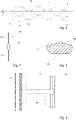
- a gasket arrangement 2 and a first heat transfer plate 4 for a plate heat exchanger are shown.
- the gasket arrangement 2 and the first heat transfer plate 4 constitute an assembly 5.
- the gasket arrangement 2 comprises a rubber gasket 6.
- the first heat transfer plate is essentially rectangular and made of stainless steel.
- the first heat transfer plate 4 is arranged between a second heat transfer plate 8 (illustrated in Fig. 2 ) and a third heat transfer plate 10 (illustrated in Fig. 2 ), and the gasket 6 seals between the first heat transfer plate 4 and the second heat transfer plate 8.
- the first, second and third heat transfer plates form part of a plate pack.
- the plates in the plate pack are all of the same type, but in alternative embodiments they could be of different types. Further, with reference to the section of the text describing the background of the invention, the heat transfer plates in the plate pack are "rotated" in relation to each other, but in alternative embodiments they could instead be "flipped" in relation to each other.
- the first heat transfer plate 4 comprises ( Figs. 1 and 2 ) a first side 12, an opposing second side 14 and first, second, third and fourth portholes 16a-d arranged in a respective corner of the first heat transfer plate 4.
- the first heat transfer plate 4 further comprises a groove 18 on the first side 12 for receiving the gasket 6.
- First and second porthole groove portions 18a and 18b, respectively, of the groove 18 extend completely around a respective one of the first and second portholes 16a and 16b.
- An annular groove portion 18e of the groove 18 extends along an outer edge 20 of the first heat transfer plate 4 and on the inside of the first and second porthole groove portions 18a and 18b, respectively, of the groove 18.
- a plurality of first link groove portions 18f, here 7, of the groove 18 extend between the first porthole groove portion 18a and the annular groove portion 18e, while a plurality of second link groove portions 18g, here 7, of the groove 18 extend between the second porthole groove portion 18b and the annular groove portion 18e.
- first heat transfer plate 4 Different areas of the first heat transfer plate 4 are provided with different corrugation patterns (not illustrated in Fig. 1 ), and the corrugation pattern within a specific plate area is adapted to the main function of this plate area.
- an outer edge portion 22 of the first heat transfer plate 4 is provided with a strengthening corrugation extending along most of the outer edge 20 of the first heat transfer plate 4 so as to give it a wave-shape.
- This corrugation which comprises alternately arranged ridges 24 and valleys 26 as seen from the first side 12 of the heat transfer plate 4, and also corrugations within other areas of the heat transfer plate 4, extend between and in an imaginary first plane p1 and an imaginary second plane p2.
- a bottom of the gasket groove 18 extends in the first plane p1.
- An imaginary intermediate plane pi arranged halfway between, and parallel to, the imaginary first and second planes p1 and p2 defines the border between the ridges 24 and the valleys 26 within the outer edge portion 22 of the first heat transfer plate 4.
- first, second and third heat transfer plates are all of the same kind, the above description of the first heat transfer plate 4 is valid also for the second and third heat transfer plates 8 and 10.
- the first side 12 of the first heat transfer plate 4 faces the second heat transfer plate 8, while the second opposing side 14 of the first heat transfer plate 4 faces the third heat transfer plate 10.
- corrugations of the first heat transfer plate 4 abut corrugations of the second and third heat transfer plates 8 and 10.
- the gasket 6 is accommodated in the gasket grooves of, and compressed between, the first and second heat transfer plates 4 and 8, with a lower side 28 of the gasket 6 ( Fig. 3 ) facing the first heat transfer plate 4 and an upper side 30 ( Fig. 3 ) of the gasket 6 facing the second heat transfer plate 8.
- a similar gasket is correspondingly arranged, and compressed between, the first and third heat transfer plates. 4 and 10
- the gasket 6 comprises, with reference to Fig. 1 , first and second porthole gasket portions 6a and 6b, respectively, arranged to be received in the first and second porthole groove portions 18a and 18b, respectively, an annular gasket portion 6e arranged to be received in the annular groove portion 18e, a plurality of first link gasket portions 6f, here 7, arranged to be received in a respective one of the first link groove portions 18f, and a plurality of second link gasket portions 6g, here 7, arranged to be received in a respective one of the second link groove portions 18g.
- the first and second porthole gasket portions 6a and 6b of the gasket 6 are arranged to surround a respective one of the first and second portholes 16a and 16b of the first heat transfer plate 4 and a respective one of the portholes of the second heat transfer plate 8, while an inside 32 of the annular gasket portion 6e of the gasket 6 is arranged to define a fluid flow channel between the first and second heat transfer plates 4 and 8.
- the first and second link gasket portions 6f and 6g are non-sealing portions of a reduced height connecting the first and second porthole gasket portions 6a and 6b and the annular gasket portion 6e. It alternative embodiments these non-sealing gasket portions may be of the same height as the rest of the gasket.
- the gasket arrangement 2 comprises rubber projections in the form of a marking tab 34, outer gasket attachment means 36 and inner gasket attachment means 38.
- the marking tab 34 and the outer gasket attachment means 36 project from an outside 40 of the gasket 6, while the inner gasket attachment means 38 project from an inside 42 of the first and second porthole gasket portions 6a and 6b, and the inside 32 of the annular gasket portion 6e, of the gasket 6.
- the marking tab 34 and a first one 36a of the outer gasket attachment means 36 project from an outer one 6f' of the first link gasket portions 6f and are illustrated in more detail in Figs. 4 and 5 , respectively.
- Each of the marking tab 34 and the first outer gasket attachment means 36a comprises an outer part or bridge 44 and 46, respectively, and a first connection part 48 and 50, respectively.
- the first connection parts 48 and 50 are arranged to connect the outer parts 44 and 46 to the gasket 6.
- the first connection parts 48 and 50 extend from the gasket 6 essentially perpendicular to a length extension of the gasket 6 where the first connection parts 48 and 50 join the gasket 6.
- a respective length extension of the outer parts 44 and 46 is essentially parallel to the length extension of the gasket 6 where the first connection parts 48 and 50 join the gasket 6.
- the first connection parts 48 and 50 have such a length that the outer parts 44 and 46 are arranged to extend just outside the first heat transfer plate 4 and, thus, the plate pack of the plate heat exchanger.
- the first connection part 48 of the marking tab 34 connects to an intermediate or center portion C of the outer part 44 of the marking tab 34, while the first connection part 50 of the outer gasket attachment means 36a connects to a first end portion E1 of the outer part 46 of the outer gasket attachment means 36a.
- the outer gasket attachment means 36a further comprises a second connection part 52 arranged to connect the outer part 46 to the gasket 6.
- the second connection part 52 extend essentially parallel to, and have a similar length as, the first connection part 50.
- the second connection part 52 of the outer gasket attachment means 36a connects to a second end portion E2 of the outer part 46 of the outer gasket attachment means 36a.
- the outer gasket attachment means 36a comprises first, second and third fingers 54, 56 and 58, respectively, extending, essentially parallel to the first and second connection parts 50 and 52, from the outer part 46 of the outer gasket attachment means 36a towards the gasket 6.
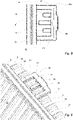
- All the outer gasket attachment means 36 are configured according to the above description of the outer gasket attachment means 36a. They are arranged to engage with the first heat transfer plate 4 to attach the gasket 6 thereto. In Fig. 6 the engagement between the first heat transfer plate 4 and one of the outer gasket attachment means 36 is illustrated, but all of the outer gasket attachment means 36 engage in a similar way with the first heat transfer plate 4.
- the first and second connection parts 50 and 52 and the second finger 56 are arranged in a respective one of the valleys 26 of the outer edge portion 22, the first and third fingers 54 and 58 are arranged under a respective one of the ridges 24 of the outer edge portion 22, and the outer part 46 extends outside the first heat transfer plate 4, essentially parallel to the outer edge 20 thereof. Accordingly, the first and second connection parts 50 and 52 and the second finger 56 of the outer gasket attachment means 36 will engage with the first side 12 of the first heat transfer plate 4, while the first and third fingers 54 and 58 of the outer gasket attachment means 36 will engage with the opposing second side 14 ( Fig. 2 ) of the first heat transfer plate 4, to fasten the gasket 6 to the first heat transfer plate 4.
- the gasket 6 When the gasket arrangement 2 is properly fastened to the first heat transfer plate 4, the gasket 6 is arranged in the groove 18, the outer gasket attachment means 36 all engage with the first heat transfer plate 4 as described above, the inner gasket attachment means 38 all engage with porthole edges of the first heat transfer plate 4 in not further described way, the first connection part 48 of the marking tab 34 is arranged in one of the valleys 26 of the outer edge portion 22 of the first heat transfer plate 4, and the outer part 44 of the marking tab 34 extends outside the first heat transfer plate 4, essentially parallel to the outer edge 20 thereof.
- the gasket arrangement 2 further comprises an RFID tag 60 of UHF-standard which is illustrated in Fig. 7.
- Figs. 4 and 5 illustrate two possible positions for the RFID tag 60, and, thus, two different embodiments of the gasket arrangement 2 according to the invention.
- the RFID tag 60 is arranged in the outer part 44 of the marking tab 34
- the RFID tag 60 is arranged in the outer part 46 of the first outer gasket attachment means 36a.
- the RFID tag 60 is embedded in the rubber and not visible from the outside, and, therefore, illustrated with ghost lines in Figs. 4 and 5 .
- a length extension of the RFID tag 60 and especially a longitudinal center axis of two antennas 62 extending from a chip 61 thereof ( Fig. 7 ), is essentially parallel to the length extension of the outer part 44 and 46, respectively.
- the antennas 62 have been illustrated with solid lines in the figures even if they in reality are formed as spirals extending around the longitudinal center axis of the antennas.
- a mold (not illustrated), which comprises a gasket portion for molding the gasket 6 and projection portions for molding the marking tab 34, the outer gasket attachment means 36 and the inner gasket attachment means 38, is used to manufacture the gasket arrangement 2.
- the mold is a conventional mold comprising two opposite parts pressed against each other to define the mold cavity, and it is not described in further detail herein.
- the projection portions for molding the marking tab 34 and the outer gasket attachment means 36 project from an outside of the gasket portion, while the projection portions for molding the inner gasket attachment means 38 project from an inside of the gasket portion.
- the RFID tag 60 is arranged in an outer portion of the projection portion for molding the marking tab 34, or in an outer portion of the projection portion for molding the first outer gasket attachment means 36a, depending on whether a gasket arrangement according to Fig. 4 or Fig. 5 is to be manufactured.
- the gasket and projection portions of the mold are filled with blanks of rubber.
- the mold is heated to plasticize or vulcanize the blanks of rubber and achieve the gasket arrangement. In connection therewith, plasticized or vulcanized rubber encapsulates the RFID tag 60 which thereby becomes embedded in the marking tab 34 or the first outer gasket arrangement 36a. After forming, the gasket arrangement is removed from the mold in one piece.
- the RFID tag is pre-programmed with a random number when received by the gasket manufacturer, or the gasket manufacturer programs the RFID tag with a random number.
- the random number should have a minimal chance of repetition or interference with other systems.
- the random number could be generated by means of the UUID4 technology.
- the random number is paired with the corresponding manufacturing batch number in a data base, which batch number, in turn, provides information on article number, material quality, manufacturing date, manufacturing parameters, etc.
- the RFID tag 60 of the gasket arrangement 2 can be read by means of a suitable reader to access all this information for full traceability of the gasket arrangement throughout its product life cycle. For example, this could facilitate claims handling.
- the random number may also be paired with additional information, like information on the customer who has bought the gasket arrangement, identity of the plate heat exchanger containing the gasket arrangement, installation date, plate heat exchanger operation parameters, etc., which information may be updated if required.
- additional information could be used to make digital twins of plate heat exchangers and facilitate and predict service and maintenance of them.
- first outer gasket attachment means 36a and the marking tab 34 need not be positioned as illustrated in Fig. 1 but can have other positions.
- the first outer gasket attachment means 36a and the marking tab 34 could instead project from the other outer one of the first link gasket portions 6f, or from a bridge portion of the gasket 6 adapted to be positioned below a center recess of the first heat transfer plate 4, which bridge portion is illustrated in Fig. 1 .
- the first outer gasket attachment means 36a and the marking tab 34 could instead project from a sealing portion of the gasket, such as from the first porthole gasket portion 6a, for example at 'A' in Fig.
- the gasket arrangement could also comprise two marking tabs housing a respective RFID tag; for example one marking tab projecting from the first porthole gasket portion 6a and one marking tab projecting from the annular gasket portion 6e.
- Such an embodiment could allow separate traceability of the first porthole gasket portion and the annular gasket portion.
- the RFID tag could be embedded also in the first connection part of the projection, with the length extension of the RFID tag being essentially parallel to the length extension of the first connection part or not.
- the RFID tag need not be designed as described above and illustrated in the drawings but could have any suitable design.
- the antennas need not be formed as three dimensional spirals but could extend, in any suitable way, in a plane.
- the antennas could extend from opposite sides of the chip with a wave-shape.
- the antennas could extend one or more turns around the chip, and the turns could have any shape, such as a round or a polygonal shape.
- the RFID tag could comprise more or less than two antennas, and the chip may have any suitable design.
- the RFID tag may be comprised in a label and thus provided on a support which may be embedded in the projection.
- the length extension of the outer part of the projection need not extend essentially perpendicular to the length extension of the first connection part of the projection, but could instead extend essentially parallel thereto to form a "prolongation" of the first connection part.
- the first outer gasket attachment means 36a need not be designed as illustrated in the figures but could have other designs.
- the first outer gasket attachment means could be designed according to US patent 4,635,715 or US patent 10,451,361 .
- All the outer gasket attachment means may, or may not, have a similar design.
- the gasket assembly illustrated in Fig. 1 is adapted for use in a plate heat exchanger of parallel flow type which means that the first and second porthole gasket portions 6a and 6b are arranged on the same side of a longitudinal center axis of the gasket arrangement.
- the present invention is equally applicable in connection with a plate heat exchanger of diagonal flow type and the first and second porthole gasket portions 6a and 6b arranged on opposite sides of a longitudinal center axis of the gasket arrangement.
- the present invention is also applicable in connection with other types of plate heat exchangers, such as fresh water generators having portholes arranged along a longitudinal center axis of the plate heat exchanger.
- the complete gasket arrangement need not be molded in one single step.
- the marking tab including the RFID tag could be molded in a first step, and the rest of the gasket arrangement could be molded in a second step.
- the pre-molded marking tab, including the RFID tag could be arranged in the mold for making the gasket arrangement and be "automatically" bonded to the gasket in connection with molding of the rest of the gasket arrangement.
- the marking tab, including the RFID tag could be molded in a separate mold, and the rest of the gasket could be molded in a separate mold, and then the marking tab and the rest of the gasket arrangement could be connected in a separate step.
- the RFID tag instead arranged embedded in the first outer gasket attachment means.
- the RFID tag need not be molded into the marking tab or the first outer gasket attachment means by letting plasticized or vulcanized rubber or other material encapsulate the RFID tag. According to an alternative manufacturing method, an incision is made in the marking tab or the first outer gasket attachment means after molding, and the RFID tag is inserted through this incision.
- the complete or a part of the gasket arrangement could be made of another material than rubber.
- the heat transfer plates could be made of another material than stainless steel, such as titanium or aluminum.
- heat transfer plates are so designed that the gasket groove and the valleys within the outer edge portion are in the same plane.
- the present invention is equally applicable in connection with heat transfer plates of other designs, for example heat transfer plates comprising gasket grooves arranged in half-plane.
- the present invention could be used in connection with other types of plate heat exchangers than purely gasketed ones, e.g. plate heat exchangers comprising partly/only permanently joined heat transfer plates, such as welded and semi-welded heat exchangers.
Landscapes
- Engineering & Computer Science (AREA)
- Physics & Mathematics (AREA)
- Thermal Sciences (AREA)
- Mechanical Engineering (AREA)
- General Engineering & Computer Science (AREA)
- Computer Networks & Wireless Communication (AREA)
- Computer Hardware Design (AREA)
- Microelectronics & Electronic Packaging (AREA)
- General Physics & Mathematics (AREA)
- Theoretical Computer Science (AREA)
- Heat-Exchange Devices With Radiators And Conduit Assemblies (AREA)
Claims (14)
- Dichtungsanordnung (2) für einen Plattenwärmetauscher, umfassend eine Dichtung (6), die so angeordnet ist, dass sie zwischen einer ersten und einer zweiten fluchtenden Wärmeübertragungsplatte (4, 8) des Plattenwärmetauschers positioniert ist, wobei eine untere Seite (28) der Dichtung (6) an der ersten Wärmeübertragungsplatte (4) anliegt und eine entgegengesetzte obere Seite (30) der Dichtung (6) an der zweiten Wärmeübertragungsplatte (8) anliegt, und einen Vorsprung (34, 36a), der von einer Außenseite (40) der Dichtung (6) vorsteht, wobei der Vorsprung (34, 36a) ein Außenteil (44, 46) mit einer Längenerstreckung umfasst und so angeordnet ist, dass er sich außerhalb der ersten und zweiten Wärmeübertragungsplatte (4, 8) erstreckt, und ein erstes Verbindungsteil (48, 50), das die Dichtung (6) und das Außenteil (44, 46) des Vorsprungs (34, 36a) miteinander verbindet, dadurch gekennzeichnet, dass sie ferner ein RFID-Tag (60) umfasst, welches zumindest teilweise in mindestens dem Außenteil (44, 46) des Vorsprungs (34, 36a) eingebettet ist.
- Dichtungsanordnung (2) nach Anspruch 1, wobei die Längenerstreckung des Außenteils (44, 46) des Vorsprungs (34, 36a) im Wesentlichen parallel zu einer Längenerstreckung des RFID-Tags (60) ist.
- Dichtungsanordnung (2) nach einem der vorhergehenden Ansprüche, wobei die Längenerstreckung des Außenteils (44, 46) des Vorsprungs (34, 36a) im Wesentlichen parallel zu einer Längenerstreckung der Dichtung (6) am ersten Verbindungsteil (48, 50) ist.
- Dichtungsanordnung (2) nach einem der vorhergehenden Ansprüche, wobei eine Längenerstreckung des ersten Verbindungsteils (48, 50) des Vorsprungs (34, 36a) im Wesentlichen senkrecht zu der Längenerstreckung des Außenteils (44, 46) des Vorsprungs (34, 36a) ist.
- Dichtungsanordnung (2) nach einem der vorhergehenden Ansprüche, wobei sich das erste Verbindungsteil (48) zwischen der Dichtung (6) und einem Zwischenabschnitt (C) des Außenteils (44) des Vorsprungs (34) erstreckt.
- Dichtungsanordnung (2) nach einem der vorhergehenden Ansprüche, wobei der Vorsprung (36a) ferner einen ersten Finger (54) umfasst, der sich von dem Außenteil (46) des Vorsprungs (36a) zu der Dichtung (6) hin erstreckt, wobei das erste Verbindungsteil (50) und der erste Finger (54) des Vorsprungs (36a) so angeordnet sind, dass sie mit entgegengesetzten Seiten (12, 14) der ersten Wärmeübertragungsplatte (4) in Eingriff kommen, um die Dichtung (6) an der ersten Wärmeübertragungsplatte (4) zu befestigen.
- Dichtungsanordnung (2) nach einem der vorhergehenden Ansprüche, wobei die Dichtung (6) einen ersten Öffnungsdichtungsabschnitt (6a), der so angeordnet ist, dass er sich um eine erste Öffnung (16a) der ersten Wärmeübertragungsplatte (4) erstreckt, einen zweiten Öffnungsdichtungsabschnitt (6b), der so angeordnet ist, dass er sich um eine zweite Öffnung (16b) der ersten Wärmeübertragungsplatte (4) erstreckt, einen ringförmigen Dichtungsabschnitt (6e), von dem eine Innenseite (32) so angeordnet ist, dass sie einen Fluidstromkanal zwischen der ersten und der zweiten Wärmeübertragungsplatte (4, 8) definiert, mindestens einen ersten Verknüpfungsdichtungsabschnitt (6f), der den ersten Öffnungsdichtungsabschnitt (6a) und den ringförmigen Dichtungsabschnitt (6e) verbindet, und mindestens einen zweiten Verknüpfungsdichtungsabschnitt (6g), der den zweiten Öffnungsdichtungsabschnitt (6b) und den ringförmigen Dichtungsabschnitt (6e) verbindet, umfasst, wobei der Vorsprung (34, 36a) von einem äußeren (6f') des mindestens einen ersten Verknüpfungsdichtungsabschnitt (6f) vorsteht.
- Dichtungsanordnung (2) nach einem der Ansprüche 1 bis 6, wobei die Dichtung (6) einen ersten Öffnungsdichtungsabschnitt (6a) umfasst, der so angeordnet ist, dass er sich um eine erste Öffnung (16a) der ersten Wärmeübertragungsplatte (4) erstreckt, wobei der Vorsprung (34, 36a) von der Außenseite (40) des ersten Öffnungsdichtungsabschnitts (6a) vorsteht.
- Dichtungsanordnung (2) nach einem der Ansprüche 1 bis 6, wobei die Dichtung (6) einen ringförmigen Dichtungsabschnitt (6e) umfasst, von dem eine Innenseite (32) so angeordnet ist, dass sie einen Fluidstromkanal zwischen der ersten und der zweiten Wärmeübertragungsplatte (4, 8) definiert, wobei der Vorsprung (34, 36a) von der Außenseite (40) des ringförmigen Dichtungsabschnitts (6e) vorsteht.
- Verfahren zum Herstellen einer Dichtungsanordnung (2) für einen Plattenwärmetauscher, wobei die Dichtungsanordnung (2) eine Dichtung (6) und einen Vorsprung (34, 36a) einschließt, der von einer Außenseite (40) der Dichtung (6) vorsteht, umfassendBereitstellen der Dichtung (6) aus einem elastomeren ersten Material,Bereitstellen des Vorsprungs (34, 36a) aus einem zweiten Material unddauerhaftes Zusammenfügen der Dichtung (6) und des Vorsprungs (34, 36a),dadurch gekennzeichnet, dass es ferner Folgendes umfasst:
Bereitstellen eines RFID-Tags (60), der zumindest teilweise in den Vorsprung (34, 36a) eingeformt ist. - Verfahren nach Anspruch 10, wobei der Schritt des Bereitstellens der Dichtung (6) Folgendes umfasst:Bereitstellen einer Form, umfassend einen Dichtungsabschnitt zum Formen der Dichtung (6) der Dichtungsanordnung (2),Anordnen mindestens eines Rohlings aus dem elastomeren ersten Material in dem Dichtungsabschnitt der Form,
undAufbringen von Wärme auf die Form, um die Dichtung (6) und das Zusammenfügen der Dichtung (6) und des Vorsprungs (34, 36a) zu erreichen. - Verfahren nach Anspruch 10, wobei die Schritte des Bereitstellens der Dichtung (6) und des Vorsprungs (34, 36a) Folgendes umfassen:Bereitstellen einer Form, umfassend einen Dichtungsabschnitt zum Formen der Dichtung (6) der Dichtungsanordnung (2), und einen Vorsprungabschnitt, der von einer Außenseite des Dichtungsabschnitts vorsteht, um den Vorsprung (34, 36a) der Dichtungsanordnung (2) zu formen,Anordnen des RFID-Tags (60) in dem Vorsprungteil der Form,Anordnen mindestens eines Rohlings aus dem elastomeren ersten Material in dem Dichtungsabschnitt der Form und mindestens eines Rohlings aus dem zweiten Material in dem Vorsprungabschnitt der Form, undAufbringen von Wärme auf die Form, um die Dichtung (6), den Vorsprung (34, 36a), den RFID-Tag (60), der zumindest teilweise in den Vorsprung (34, 36a) eingeformt ist, und das Zusammenfügen der Dichtung (6) und des Vorsprungs (34, 36a) zu erreichen.
- Verfahren nach einem der Ansprüche 10 bis 12, wobei es sich bei dem elastomeren ersten Material und dem zweiten Material um das gleiche Material handelt.
- Aufbau (5), umfassend eine erste Wärmeübertragungsplatte (4) und eine Dichtungsanordnung (2) nach einem der Ansprüche 1 bis 9, wobei die erste Wärmeübertragungsplatte (4) eine Nut (18) umfasst, die die Dichtung (6) aufnimmt, und sich das Außenteil (44, 46) des Vorsprungs (34, 36a) nach außerhalb der ersten Wärmeübertragungsplatte (4) erstreckt.
Priority Applications (10)
| Application Number | Priority Date | Filing Date | Title |
|---|---|---|---|
| EP20170989.6A EP3901552B1 (de) | 2020-04-23 | 2020-04-23 | Dichtungsanordnung, verfahren zur herstellung einer dichtungsanordnung und anordnung |
| DK20170989.6T DK3901552T3 (da) | 2020-04-23 | 2020-04-23 | Pakningsanordning, fremgangsmåde til fremstilling af en pakningsanordning og anordning |
| PL20170989.6T PL3901552T3 (pl) | 2020-04-23 | 2020-04-23 | Układ uszczelki, metoda wytwarzania układu i zespołu uszczelek |
| ES20170989T ES2935169T3 (es) | 2020-04-23 | 2020-04-23 | Disposición de junta, método de fabricación de una disposición de junta, y conjunto |
| BR112022019860A BR112022019860A2 (pt) | 2020-04-23 | 2021-03-25 | Arranjo de gaxeta, método para fabricar um arranjo de gaxeta, e, montagem |
| KR1020227040424A KR102778786B1 (ko) | 2020-04-23 | 2021-03-25 | 가스켓 배열체, 가스켓 배열체를 제조하는 방법 및 조립체 |
| JP2022564627A JP7529798B2 (ja) | 2020-04-23 | 2021-03-25 | ガスケット配列、ガスケット配列の製造方法およびそのアセンブリ |
| CN202180030028.8A CN115398175A (zh) | 2020-04-23 | 2021-03-25 | 垫片布置、制造垫片布置的方法以及组件 |
| US17/919,857 US20230160644A1 (en) | 2020-04-23 | 2021-03-25 | Gasket arrangement, method of manufacturing a gasket arrangement and assembly |
| PCT/EP2021/057681 WO2021213772A1 (en) | 2020-04-23 | 2021-03-25 | Gasket arrangement, method of manufacturing a gasket arrangement and assembly |
Applications Claiming Priority (1)
| Application Number | Priority Date | Filing Date | Title |
|---|---|---|---|
| EP20170989.6A EP3901552B1 (de) | 2020-04-23 | 2020-04-23 | Dichtungsanordnung, verfahren zur herstellung einer dichtungsanordnung und anordnung |
Publications (2)
| Publication Number | Publication Date |
|---|---|
| EP3901552A1 EP3901552A1 (de) | 2021-10-27 |
| EP3901552B1 true EP3901552B1 (de) | 2022-12-07 |
Family
ID=70417393
Family Applications (1)
| Application Number | Title | Priority Date | Filing Date |
|---|---|---|---|
| EP20170989.6A Active EP3901552B1 (de) | 2020-04-23 | 2020-04-23 | Dichtungsanordnung, verfahren zur herstellung einer dichtungsanordnung und anordnung |
Country Status (10)
| Country | Link |
|---|---|
| US (1) | US20230160644A1 (de) |
| EP (1) | EP3901552B1 (de) |
| JP (1) | JP7529798B2 (de) |
| KR (1) | KR102778786B1 (de) |
| CN (1) | CN115398175A (de) |
| BR (1) | BR112022019860A2 (de) |
| DK (1) | DK3901552T3 (de) |
| ES (1) | ES2935169T3 (de) |
| PL (1) | PL3901552T3 (de) |
| WO (1) | WO2021213772A1 (de) |
Family Cites Families (9)
| Publication number | Priority date | Publication date | Assignee | Title |
|---|---|---|---|---|
| SE8303449L (sv) * | 1983-06-16 | 1984-12-17 | Alfa Laval Thermal | Packningsarrangemang for plattvermevexlare |
| JP3069592B2 (ja) * | 1990-02-21 | 2000-07-24 | 株式会社日阪製作所 | プレート式熱交換器 |
| JP4990224B2 (ja) * | 2008-06-05 | 2012-08-01 | 岩井機械工業株式会社 | Rfidタグを取り付けた流体製品製造プラント設備のシール部材及びその取り付け方法 |
| SE535236C2 (sv) * | 2010-10-22 | 2012-06-05 | Alfa Laval Corp Ab | Värmeväxlarplatta och plattvärmeväxlare |
| HUE036903T2 (hu) * | 2013-01-30 | 2018-08-28 | Alfa Laval Corp Ab | Rögzítõeszköz, tömítési elrendezés és összeállítás |
| EP2886998B1 (de) * | 2013-12-18 | 2018-04-18 | Alfa Laval Corporate AB | Befestigungsmittel, Dichtungsanordnung, Wärmetauscherplatte und Baugruppe |
| EP3001131A1 (de) * | 2014-09-26 | 2016-03-30 | Alfa Laval Corporate AB | Lukendichtung für einen Plattenwärmeaustauscher, Plattenpaket und Plattenwärmetauscher mit einer solchen Lukendichtung |
| WO2019164551A1 (en) * | 2018-02-22 | 2019-08-29 | Trelleborg Sealing Solutions Us, Inc. | System and method for detecting a condition of a seal |
| GB2574021B (en) * | 2018-05-22 | 2023-03-01 | Trp Sealing Systems Ltd | Gasket for a plate heat exchanger |
-
2020
- 2020-04-23 PL PL20170989.6T patent/PL3901552T3/pl unknown
- 2020-04-23 ES ES20170989T patent/ES2935169T3/es active Active
- 2020-04-23 DK DK20170989.6T patent/DK3901552T3/da active
- 2020-04-23 EP EP20170989.6A patent/EP3901552B1/de active Active
-
2021
- 2021-03-25 BR BR112022019860A patent/BR112022019860A2/pt active Search and Examination
- 2021-03-25 WO PCT/EP2021/057681 patent/WO2021213772A1/en not_active Ceased
- 2021-03-25 KR KR1020227040424A patent/KR102778786B1/ko active Active
- 2021-03-25 US US17/919,857 patent/US20230160644A1/en not_active Abandoned
- 2021-03-25 JP JP2022564627A patent/JP7529798B2/ja active Active
- 2021-03-25 CN CN202180030028.8A patent/CN115398175A/zh active Pending
Also Published As
| Publication number | Publication date |
|---|---|
| US20230160644A1 (en) | 2023-05-25 |
| JP2023523045A (ja) | 2023-06-01 |
| ES2935169T3 (es) | 2023-03-02 |
| DK3901552T3 (da) | 2023-03-06 |
| KR20230012506A (ko) | 2023-01-26 |
| PL3901552T3 (pl) | 2023-01-16 |
| BR112022019860A2 (pt) | 2022-11-22 |
| WO2021213772A1 (en) | 2021-10-28 |
| KR102778786B1 (ko) | 2025-03-12 |
| JP7529798B2 (ja) | 2024-08-06 |
| EP3901552A1 (de) | 2021-10-27 |
| CN115398175A (zh) | 2022-11-25 |
Similar Documents
| Publication | Publication Date | Title |
|---|---|---|
| US8002023B2 (en) | Heat exchanger and its manufacturing method | |
| US5327958A (en) | Stacked-plate heat exchanger | |
| US5699856A (en) | Bank of plates for heat exchanger and method of assembling such a bank of plates | |
| EP2370773B1 (de) | Verstärkter wärmetauscher | |
| JP4981063B2 (ja) | プレート熱交換器用の手段 | |
| EP2963375B1 (de) | Plattenwärmetauscher | |
| AU2349292A (en) | A multi-walled plate element | |
| US4967836A (en) | Heat exchanger and method of making a gasket seal of the heat exhanger | |
| EP0469160B1 (de) | Plattenwärmetauscher | |
| EP3901552B1 (de) | Dichtungsanordnung, verfahren zur herstellung einer dichtungsanordnung und anordnung | |
| US12379165B2 (en) | Heat exchanger plate, and a plate heat exchanger | |
| EP2370771B1 (de) | Gelöteter Wärmetauscher | |
| EP0134155B1 (de) | Wärmeübertragungsplatte | |
| JP4990224B2 (ja) | Rfidタグを取り付けた流体製品製造プラント設備のシール部材及びその取り付け方法 | |
| JP2022534372A (ja) | プレート式熱交換器、およびプレート式熱交換器の製造方法 | |
| KR101980359B1 (ko) | 적층식 판형 열교환기 | |
| JP3997041B2 (ja) | プレート弁 | |
| EP0247043B1 (de) | Beschichtung für eingangs- und auslassöffnungen eines platten wärmeaustauschers | |
| EP2251631A1 (de) | Heizvorrichtung und Verfahren zu deren Herstellung | |
| EP4386301A1 (de) | Doppelplatten-wärmetauscher | |
| CN112747613B (zh) | 用于板式换热器的换热板和板式换热器 |
Legal Events
| Date | Code | Title | Description |
|---|---|---|---|
| PUAI | Public reference made under article 153(3) epc to a published international application that has entered the european phase |
Free format text: ORIGINAL CODE: 0009012 |
|
| STAA | Information on the status of an ep patent application or granted ep patent |
Free format text: STATUS: THE APPLICATION HAS BEEN PUBLISHED |
|
| AK | Designated contracting states |
Kind code of ref document: A1 Designated state(s): AL AT BE BG CH CY CZ DE DK EE ES FI FR GB GR HR HU IE IS IT LI LT LU LV MC MK MT NL NO PL PT RO RS SE SI SK SM TR |
|
| B565 | Issuance of search results under rule 164(2) epc |
Effective date: 20201023 |
|
| STAA | Information on the status of an ep patent application or granted ep patent |
Free format text: STATUS: REQUEST FOR EXAMINATION WAS MADE |
|
| 17P | Request for examination filed |
Effective date: 20220406 |
|
| RBV | Designated contracting states (corrected) |
Designated state(s): AL AT BE BG CH CY CZ DE DK EE ES FI FR GB GR HR HU IE IS IT LI LT LU LV MC MK MT NL NO PL PT RO RS SE SI SK SM TR |
|
| GRAP | Despatch of communication of intention to grant a patent |
Free format text: ORIGINAL CODE: EPIDOSNIGR1 |
|
| STAA | Information on the status of an ep patent application or granted ep patent |
Free format text: STATUS: GRANT OF PATENT IS INTENDED |
|
| RIC1 | Information provided on ipc code assigned before grant |
Ipc: F28F 3/10 20060101AFI20220720BHEP |
|
| INTG | Intention to grant announced |
Effective date: 20220808 |
|
| RIN1 | Information on inventor provided before grant (corrected) |
Inventor name: BERTILSSON, KLAS Inventor name: GUSTAFSSON, HELEN Inventor name: NYANDER, ANDERS |
|
| GRAS | Grant fee paid |
Free format text: ORIGINAL CODE: EPIDOSNIGR3 |
|
| GRAA | (expected) grant |
Free format text: ORIGINAL CODE: 0009210 |
|
| STAA | Information on the status of an ep patent application or granted ep patent |
Free format text: STATUS: THE PATENT HAS BEEN GRANTED |
|
| AK | Designated contracting states |
Kind code of ref document: B1 Designated state(s): AL AT BE BG CH CY CZ DE DK EE ES FI FR GB GR HR HU IE IS IT LI LT LU LV MC MK MT NL NO PL PT RO RS SE SI SK SM TR |
|
| REG | Reference to a national code |
Ref country code: GB Ref legal event code: FG4D |
|
| REG | Reference to a national code |
Ref country code: CH Ref legal event code: EP Ref country code: AT Ref legal event code: REF Ref document number: 1536550 Country of ref document: AT Kind code of ref document: T Effective date: 20221215 |
|
| REG | Reference to a national code |
Ref country code: DE Ref legal event code: R096 Ref document number: 602020006717 Country of ref document: DE |
|
| REG | Reference to a national code |
Ref country code: IE Ref legal event code: FG4D |
|
| REG | Reference to a national code |
Ref country code: SE Ref legal event code: TRGR |
|
| REG | Reference to a national code |
Ref country code: ES Ref legal event code: FG2A Ref document number: 2935169 Country of ref document: ES Kind code of ref document: T3 Effective date: 20230302 |
|
| REG | Reference to a national code |
Ref country code: DK Ref legal event code: T3 Effective date: 20230228 |
|
| REG | Reference to a national code |
Ref country code: LT Ref legal event code: MG9D |
|
| REG | Reference to a national code |
Ref country code: NL Ref legal event code: MP Effective date: 20221207 |
|
| PG25 | Lapsed in a contracting state [announced via postgrant information from national office to epo] |
Ref country code: NO Free format text: LAPSE BECAUSE OF FAILURE TO SUBMIT A TRANSLATION OF THE DESCRIPTION OR TO PAY THE FEE WITHIN THE PRESCRIBED TIME-LIMIT Effective date: 20230307 Ref country code: LT Free format text: LAPSE BECAUSE OF FAILURE TO SUBMIT A TRANSLATION OF THE DESCRIPTION OR TO PAY THE FEE WITHIN THE PRESCRIBED TIME-LIMIT Effective date: 20221207 Ref country code: FI Free format text: LAPSE BECAUSE OF FAILURE TO SUBMIT A TRANSLATION OF THE DESCRIPTION OR TO PAY THE FEE WITHIN THE PRESCRIBED TIME-LIMIT Effective date: 20221207 |
|
| REG | Reference to a national code |
Ref country code: AT Ref legal event code: MK05 Ref document number: 1536550 Country of ref document: AT Kind code of ref document: T Effective date: 20221207 |
|
| PG25 | Lapsed in a contracting state [announced via postgrant information from national office to epo] |
Ref country code: RS Free format text: LAPSE BECAUSE OF FAILURE TO SUBMIT A TRANSLATION OF THE DESCRIPTION OR TO PAY THE FEE WITHIN THE PRESCRIBED TIME-LIMIT Effective date: 20221207 Ref country code: LV Free format text: LAPSE BECAUSE OF FAILURE TO SUBMIT A TRANSLATION OF THE DESCRIPTION OR TO PAY THE FEE WITHIN THE PRESCRIBED TIME-LIMIT Effective date: 20221207 Ref country code: HR Free format text: LAPSE BECAUSE OF FAILURE TO SUBMIT A TRANSLATION OF THE DESCRIPTION OR TO PAY THE FEE WITHIN THE PRESCRIBED TIME-LIMIT Effective date: 20221207 Ref country code: GR Free format text: LAPSE BECAUSE OF FAILURE TO SUBMIT A TRANSLATION OF THE DESCRIPTION OR TO PAY THE FEE WITHIN THE PRESCRIBED TIME-LIMIT Effective date: 20230308 |
|
| P01 | Opt-out of the competence of the unified patent court (upc) registered |
Effective date: 20230424 |
|
| PG25 | Lapsed in a contracting state [announced via postgrant information from national office to epo] |
Ref country code: NL Free format text: LAPSE BECAUSE OF FAILURE TO SUBMIT A TRANSLATION OF THE DESCRIPTION OR TO PAY THE FEE WITHIN THE PRESCRIBED TIME-LIMIT Effective date: 20221207 |
|
| PG25 | Lapsed in a contracting state [announced via postgrant information from national office to epo] |
Ref country code: SM Free format text: LAPSE BECAUSE OF FAILURE TO SUBMIT A TRANSLATION OF THE DESCRIPTION OR TO PAY THE FEE WITHIN THE PRESCRIBED TIME-LIMIT Effective date: 20221207 Ref country code: RO Free format text: LAPSE BECAUSE OF FAILURE TO SUBMIT A TRANSLATION OF THE DESCRIPTION OR TO PAY THE FEE WITHIN THE PRESCRIBED TIME-LIMIT Effective date: 20221207 Ref country code: PT Free format text: LAPSE BECAUSE OF FAILURE TO SUBMIT A TRANSLATION OF THE DESCRIPTION OR TO PAY THE FEE WITHIN THE PRESCRIBED TIME-LIMIT Effective date: 20230410 Ref country code: EE Free format text: LAPSE BECAUSE OF FAILURE TO SUBMIT A TRANSLATION OF THE DESCRIPTION OR TO PAY THE FEE WITHIN THE PRESCRIBED TIME-LIMIT Effective date: 20221207 Ref country code: CZ Free format text: LAPSE BECAUSE OF FAILURE TO SUBMIT A TRANSLATION OF THE DESCRIPTION OR TO PAY THE FEE WITHIN THE PRESCRIBED TIME-LIMIT Effective date: 20221207 Ref country code: AT Free format text: LAPSE BECAUSE OF FAILURE TO SUBMIT A TRANSLATION OF THE DESCRIPTION OR TO PAY THE FEE WITHIN THE PRESCRIBED TIME-LIMIT Effective date: 20221207 |
|
| PG25 | Lapsed in a contracting state [announced via postgrant information from national office to epo] |
Ref country code: SK Free format text: LAPSE BECAUSE OF FAILURE TO SUBMIT A TRANSLATION OF THE DESCRIPTION OR TO PAY THE FEE WITHIN THE PRESCRIBED TIME-LIMIT Effective date: 20221207 Ref country code: IS Free format text: LAPSE BECAUSE OF FAILURE TO SUBMIT A TRANSLATION OF THE DESCRIPTION OR TO PAY THE FEE WITHIN THE PRESCRIBED TIME-LIMIT Effective date: 20230407 Ref country code: AL Free format text: LAPSE BECAUSE OF FAILURE TO SUBMIT A TRANSLATION OF THE DESCRIPTION OR TO PAY THE FEE WITHIN THE PRESCRIBED TIME-LIMIT Effective date: 20221207 |
|
| REG | Reference to a national code |
Ref country code: DE Ref legal event code: R097 Ref document number: 602020006717 Country of ref document: DE |
|
| PLBE | No opposition filed within time limit |
Free format text: ORIGINAL CODE: 0009261 |
|
| STAA | Information on the status of an ep patent application or granted ep patent |
Free format text: STATUS: NO OPPOSITION FILED WITHIN TIME LIMIT |
|
| 26N | No opposition filed |
Effective date: 20230908 |
|
| PG25 | Lapsed in a contracting state [announced via postgrant information from national office to epo] |
Ref country code: SI Free format text: LAPSE BECAUSE OF FAILURE TO SUBMIT A TRANSLATION OF THE DESCRIPTION OR TO PAY THE FEE WITHIN THE PRESCRIBED TIME-LIMIT Effective date: 20221207 |
|
| REG | Reference to a national code |
Ref country code: CH Ref legal event code: PL |
|
| PG25 | Lapsed in a contracting state [announced via postgrant information from national office to epo] |
Ref country code: LU Free format text: LAPSE BECAUSE OF NON-PAYMENT OF DUE FEES Effective date: 20230423 |
|
| REG | Reference to a national code |
Ref country code: BE Ref legal event code: MM Effective date: 20230430 |
|
| PG25 | Lapsed in a contracting state [announced via postgrant information from national office to epo] |
Ref country code: MC Free format text: LAPSE BECAUSE OF FAILURE TO SUBMIT A TRANSLATION OF THE DESCRIPTION OR TO PAY THE FEE WITHIN THE PRESCRIBED TIME-LIMIT Effective date: 20221207 |
|
| PG25 | Lapsed in a contracting state [announced via postgrant information from national office to epo] |
Ref country code: MC Free format text: LAPSE BECAUSE OF FAILURE TO SUBMIT A TRANSLATION OF THE DESCRIPTION OR TO PAY THE FEE WITHIN THE PRESCRIBED TIME-LIMIT Effective date: 20221207 Ref country code: LI Free format text: LAPSE BECAUSE OF NON-PAYMENT OF DUE FEES Effective date: 20230430 Ref country code: CH Free format text: LAPSE BECAUSE OF NON-PAYMENT OF DUE FEES Effective date: 20230430 |
|
| REG | Reference to a national code |
Ref country code: IE Ref legal event code: MM4A |
|
| PG25 | Lapsed in a contracting state [announced via postgrant information from national office to epo] |
Ref country code: BE Free format text: LAPSE BECAUSE OF NON-PAYMENT OF DUE FEES Effective date: 20230430 |
|
| PG25 | Lapsed in a contracting state [announced via postgrant information from national office to epo] |
Ref country code: IE Free format text: LAPSE BECAUSE OF NON-PAYMENT OF DUE FEES Effective date: 20230423 |
|
| PG25 | Lapsed in a contracting state [announced via postgrant information from national office to epo] |
Ref country code: IE Free format text: LAPSE BECAUSE OF NON-PAYMENT OF DUE FEES Effective date: 20230423 |
|
| PG25 | Lapsed in a contracting state [announced via postgrant information from national office to epo] |
Ref country code: BG Free format text: LAPSE BECAUSE OF FAILURE TO SUBMIT A TRANSLATION OF THE DESCRIPTION OR TO PAY THE FEE WITHIN THE PRESCRIBED TIME-LIMIT Effective date: 20221207 |
|
| PG25 | Lapsed in a contracting state [announced via postgrant information from national office to epo] |
Ref country code: BG Free format text: LAPSE BECAUSE OF FAILURE TO SUBMIT A TRANSLATION OF THE DESCRIPTION OR TO PAY THE FEE WITHIN THE PRESCRIBED TIME-LIMIT Effective date: 20221207 |
|
| PGFP | Annual fee paid to national office [announced via postgrant information from national office to epo] |
Ref country code: DE Payment date: 20250305 Year of fee payment: 6 |
|
| PGFP | Annual fee paid to national office [announced via postgrant information from national office to epo] |
Ref country code: DK Payment date: 20250411 Year of fee payment: 6 Ref country code: ES Payment date: 20250506 Year of fee payment: 6 |
|
| PG25 | Lapsed in a contracting state [announced via postgrant information from national office to epo] |
Ref country code: CY Free format text: LAPSE BECAUSE OF FAILURE TO SUBMIT A TRANSLATION OF THE DESCRIPTION OR TO PAY THE FEE WITHIN THE PRESCRIBED TIME-LIMIT; INVALID AB INITIO Effective date: 20200423 |
|
| PGFP | Annual fee paid to national office [announced via postgrant information from national office to epo] |
Ref country code: TR Payment date: 20250410 Year of fee payment: 6 |
|
| PG25 | Lapsed in a contracting state [announced via postgrant information from national office to epo] |
Ref country code: HU Free format text: LAPSE BECAUSE OF FAILURE TO SUBMIT A TRANSLATION OF THE DESCRIPTION OR TO PAY THE FEE WITHIN THE PRESCRIBED TIME-LIMIT; INVALID AB INITIO Effective date: 20200423 |
|
| PGFP | Annual fee paid to national office [announced via postgrant information from national office to epo] |
Ref country code: SE Payment date: 20260312 Year of fee payment: 7 |
|
| PGFP | Annual fee paid to national office [announced via postgrant information from national office to epo] |
Ref country code: GB Payment date: 20260312 Year of fee payment: 7 |
|
| PGFP | Annual fee paid to national office [announced via postgrant information from national office to epo] |
Ref country code: IT Payment date: 20260320 Year of fee payment: 7 |
|
| PGFP | Annual fee paid to national office [announced via postgrant information from national office to epo] |
Ref country code: FR Payment date: 20260309 Year of fee payment: 7 |
|
| PGFP | Annual fee paid to national office [announced via postgrant information from national office to epo] |
Ref country code: PL Payment date: 20260313 Year of fee payment: 7 |