EP3901467A1 - Double-inlet air extractor - Google Patents
Double-inlet air extractor Download PDFInfo
- Publication number
- EP3901467A1 EP3901467A1 EP19899590.4A EP19899590A EP3901467A1 EP 3901467 A1 EP3901467 A1 EP 3901467A1 EP 19899590 A EP19899590 A EP 19899590A EP 3901467 A1 EP3901467 A1 EP 3901467A1
- Authority
- EP
- European Patent Office
- Prior art keywords
- cover
- opening
- main body
- air
- central
- Prior art date
- Legal status (The legal status is an assumption and is not a legal conclusion. Google has not performed a legal analysis and makes no representation as to the accuracy of the status listed.)
- Pending
Links
- 238000000926 separation method Methods 0.000 claims description 22
- 238000009423 ventilation Methods 0.000 description 5
- 238000004140 cleaning Methods 0.000 description 3
- 239000000428 dust Substances 0.000 description 2
- 238000000605 extraction Methods 0.000 description 2
- 238000001746 injection moulding Methods 0.000 description 2
- 239000000463 material Substances 0.000 description 2
- 238000010521 absorption reaction Methods 0.000 description 1
- 230000003670 easy-to-clean Effects 0.000 description 1
- 230000037431 insertion Effects 0.000 description 1
- 238000003780 insertion Methods 0.000 description 1
- 230000001788 irregular Effects 0.000 description 1
- 238000000465 moulding Methods 0.000 description 1
- 230000001681 protective effect Effects 0.000 description 1
- 239000000243 solution Substances 0.000 description 1
Images


Classifications
-
- F—MECHANICAL ENGINEERING; LIGHTING; HEATING; WEAPONS; BLASTING
- F04—POSITIVE - DISPLACEMENT MACHINES FOR LIQUIDS; PUMPS FOR LIQUIDS OR ELASTIC FLUIDS
- F04D—NON-POSITIVE-DISPLACEMENT PUMPS
- F04D25/00—Pumping installations or systems
- F04D25/02—Units comprising pumps and their driving means
- F04D25/08—Units comprising pumps and their driving means the working fluid being air, e.g. for ventilation
- F04D25/12—Units comprising pumps and their driving means the working fluid being air, e.g. for ventilation the unit being adapted for mounting in apertures
-
- F—MECHANICAL ENGINEERING; LIGHTING; HEATING; WEAPONS; BLASTING
- F04—POSITIVE - DISPLACEMENT MACHINES FOR LIQUIDS; PUMPS FOR LIQUIDS OR ELASTIC FLUIDS
- F04D—NON-POSITIVE-DISPLACEMENT PUMPS
- F04D29/00—Details, component parts, or accessories
- F04D29/40—Casings; Connections of working fluid
- F04D29/42—Casings; Connections of working fluid for radial or helico-centrifugal pumps
- F04D29/4206—Casings; Connections of working fluid for radial or helico-centrifugal pumps especially adapted for elastic fluid pumps
- F04D29/4226—Fan casings
- F04D29/424—Double entry casings
-
- F—MECHANICAL ENGINEERING; LIGHTING; HEATING; WEAPONS; BLASTING
- F04—POSITIVE - DISPLACEMENT MACHINES FOR LIQUIDS; PUMPS FOR LIQUIDS OR ELASTIC FLUIDS
- F04D—NON-POSITIVE-DISPLACEMENT PUMPS
- F04D29/00—Details, component parts, or accessories
- F04D29/40—Casings; Connections of working fluid
- F04D29/52—Casings; Connections of working fluid for axial pumps
- F04D29/522—Casings; Connections of working fluid for axial pumps especially adapted for elastic fluid pumps
- F04D29/524—Casings; Connections of working fluid for axial pumps especially adapted for elastic fluid pumps shiftable members for obturating part of the flow path
-
- F—MECHANICAL ENGINEERING; LIGHTING; HEATING; WEAPONS; BLASTING
- F04—POSITIVE - DISPLACEMENT MACHINES FOR LIQUIDS; PUMPS FOR LIQUIDS OR ELASTIC FLUIDS
- F04D—NON-POSITIVE-DISPLACEMENT PUMPS
- F04D29/00—Details, component parts, or accessories
- F04D29/40—Casings; Connections of working fluid
- F04D29/52—Casings; Connections of working fluid for axial pumps
- F04D29/54—Fluid-guiding means, e.g. diffusers
- F04D29/541—Specially adapted for elastic fluid pumps
-
- F—MECHANICAL ENGINEERING; LIGHTING; HEATING; WEAPONS; BLASTING
- F04—POSITIVE - DISPLACEMENT MACHINES FOR LIQUIDS; PUMPS FOR LIQUIDS OR ELASTIC FLUIDS
- F04D—NON-POSITIVE-DISPLACEMENT PUMPS
- F04D29/00—Details, component parts, or accessories
- F04D29/70—Suction grids; Strainers; Dust separation; Cleaning
- F04D29/701—Suction grids; Strainers; Dust separation; Cleaning especially adapted for elastic fluid pumps
- F04D29/703—Suction grids; Strainers; Dust separation; Cleaning especially adapted for elastic fluid pumps specially for fans, e.g. fan guards
-
- F—MECHANICAL ENGINEERING; LIGHTING; HEATING; WEAPONS; BLASTING
- F05—INDEXING SCHEMES RELATING TO ENGINES OR PUMPS IN VARIOUS SUBCLASSES OF CLASSES F01-F04
- F05D—INDEXING SCHEME FOR ASPECTS RELATING TO NON-POSITIVE-DISPLACEMENT MACHINES OR ENGINES, GAS-TURBINES OR JET-PROPULSION PLANTS
- F05D2250/00—Geometry
- F05D2250/50—Inlet or outlet
- F05D2250/51—Inlet
-
- F—MECHANICAL ENGINEERING; LIGHTING; HEATING; WEAPONS; BLASTING
- F24—HEATING; RANGES; VENTILATING
- F24F—AIR-CONDITIONING; AIR-HUMIDIFICATION; VENTILATION; USE OF AIR CURRENTS FOR SCREENING
- F24F7/00—Ventilation
- F24F7/04—Ventilation with ducting systems, e.g. by double walls; with natural circulation
- F24F7/06—Ventilation with ducting systems, e.g. by double walls; with natural circulation with forced air circulation, e.g. by fan positioning of a ventilator in or against a conduit
- F24F7/10—Ventilation with ducting systems, e.g. by double walls; with natural circulation with forced air circulation, e.g. by fan positioning of a ventilator in or against a conduit with air supply, or exhaust, through perforated wall, floor or ceiling
Definitions
- the present invention relates to an air extractor designed with a double inlet for the intake of air in order to achieve efficient and comfortable ventilation conditions in bathrooms, kitchens and similar rooms of residential or commercial establishments.
- the air extractors comprise a main body wherein a fan-motor assembly is disposed for the absorption of the air to be extracted and a cover which is disposed over the upper end of the main body, closing it at said end. See for example document EP1816728B1 , or document EP2012412B1 .
- the main body of the air extractor has at the upper end thereof an opening for the intake of air, the fan of the fan-motor assembly being disposed approximately in said opening in the main body, and the main body having a lower end for connection with the air exhaust duct.
- the cover which closes the upper end of the main body has a central opening provided with a grate, said central opening in the cover being aligned with the opening in the main body wherein the fan is disposed, such that the air is drawn in by the fan from the central opening in the cover to the opening in the main body in order to lead it to the exhaust duct.
- the extractor During the use of the extractor, it is common for dust, and other dirt dispersed in the air, to tend to stay adhered to the grate, and since the grate is visible, this results in an unsuitable aesthetic appearance of the extractor.
- the extractors are generally located in elevated positions of the premises, such as in the ceiling, or in the upper portion of a wall, such that the access to them for the cleaning thereof is especially difficult, which causes them to not be cleaned as often as necessary in order to improve the appearance thereof. This problem is aggravated by the dirty conditions of the premises wherein the extractor is disposed, for which reason the grate tends to get dirty after a short time of use.
- air extractors which have a blind cover without a central opening, and without a grate, such that dust does not accumulate in a visible area of the extractor, thus improving the aesthetic appearance thereof.
- an air extractor with a double inlet for the intake of air which enables efficient ventilation conditions to be achieved in the premises to be ventilated in addition to having an improved aesthetic appearance since dirt does not accumulate in a visible area of the extractor.
- the double-inlet air extractor proposed by the invention comprises:
- the cover is separated from the opening in the upper end of the main body by a first distance, such that between the cover and the opening in the upper end of the main body a lateral inlet for the intake of air is defined for leading the air from the lateral inlet to the opening in the upper end of the main body.
- the cover has a central opening that is partially covered by a central cap, the central cap being separated from the central opening in the cover by a second distance, such that a front inlet for the intake of air is defined between the central cap and the central opening in the cover for leading the air from the front inlet to the opening in the main body.
- the extractor enables a double inlet for the intake of air to be established, the lateral inlet defined between the cover and the main body, and the front inlet defined between the cover and the central cap, which improve the ventilation conditions of the air extractor.
- the arrangement of the lateral inlet for the intake of air with respect to the opening in the main body causes the air flow to have to make a turn in order to be directed to the opening, with which impacts and turbulences can be generated which affect the extraction performance of the air; however, the front inlet for the intake of air helps to direct that flow of air which enters through the lateral inlet, facilitating the rotation, such that said impacts and turbulence are reduced.
- the central cap is disposed partially covering the central opening in the cover through which the extractor frontally draws in the air, such that the aesthetic appearance of the extractor is improved as there are no visible portions thereof wherein dirt accumulates, since they are hidden by the central cap.
- the air extractor object of the invention has very advantageous features for the function for which it is intended, acquiring a life of its own and a preferential character with respect to the conventional air extractors used for that function.
- Figure 1 shows an embodiment of the air extractor for the ventilation of bathrooms, kitchens, or similar rooms in residential or commercial premises.
- the air extractor comprises a main body (10), a cover (20) which is disposed over the main body (10) and a fan-motor assembly (30) which is accommodated inside the main body (10).
- the main body (10) has an upper end (11) wherein there is an opening (12) through which the fan-motor assembly (30) draws in air, and a lower end (13), opposite from the upper end (11), for the connection of the main body (10) with an air exhaust duct (not shown).
- the fan of the fan-motor assembly (30) is disposed in the opening (12) in the upper end (11) of the main body (10) in order to cause the intake of air through the opening (12).
- the opening (12) in the upper end (11) of the main body (10) has a grate (14) for protection against possible contacts of a user with the fan-motor assembly (30) if the cover (20) is removed with the extractor running.
- the operating electronics of the extractor are accommodated in the upper end (11) of the main body (10).
- the cover (20) has a central opening (21), the central opening (21) in the cover (20) being partially covered by a central cap (40).
- the cover (20) is separated from the opening (12) in the upper end (11) of the main body (10) by a first distance (D), such that a lateral inlet (S) for the intake of air is defined, while on the other hand, the central cap (40) is separated from the central opening (21) in the cover (20) by a second distance (d), such that a front inlet (F) for the intake of air is defined.
- the fan of the fan-motor assembly (30) located in the opening (12) in the main body (10) draws in the air in order to lead it from the lateral inlet (S) for the intake of air to the opening (12) in the main body (10), and on the other hand, the fan also draws in the air in order to lead it from the front inlet (F) for the intake of air to the front opening (21) in the cover (20), and from there to the opening (12) in the main body (10), all the air drawn in being finally evacuated through the air exhaust duct which connects to the lower end (13) of the main body (10).
- the opening (12) in the main body (10) and the central opening (21) in the cover (20) are aligned, the central cap (40) being disposed aligned with both openings (12,21) in the main body (10) and the cover (20). In this manner, the central cap (40) is disposed preventing the front view of the grate (14) which covers the opening (12) in the main body, wherein dirt can accumulate.
- the imaginary axis which passes through the centre of the opening (12) in the main body (10) and the imaginary axis which passes through the centre of the central opening (21) in the cover (20) are coaxial, the imaginary axis which passes through the centre of the central cap (40) being equally aligned with the axes of both openings (12,21) in the main body (10) and in the cover (20).
- the central cap (40) has an outer dimension which is equal to, or smaller than, the inner dimension of the central opening (21) in the cover (20).
- the vertical projection of the central cap (40) is equal to or smaller than the vertical projection of the central opening (21).
- the extractor additionally comprises joining means (15,16,22,23) in order to establish a removable joint between the cover (20) and the upper end (11) of the main body (10). In this manner, the cover (20) can be disassembled from the main body (10) in order to facilitate cleaning tasks when necessary.
- one (16,23) of the joining means (15,16,22,23) has a different shape than the other joining means (15,22) in order to establish an unequivocal assembly of the cover (20) on the main body (10).
- the different joining means (16,23) are additionally used to accommodate a light indicator of an operating state of the extractor.
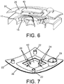
- the central cap (40) is joined to the cover (20) through supports (24).
- the supports (24) have a laminar configuration with a thinner cross section which is disposed facing the front inlet (F) for the intake of air. In this manner, the supports (24) offer a minimum resistance to the passage of air, thus reducing the possible noise that may be generated.
- the supports (24) are disposed in positions diametrically opposite and equidistant from each other, each of the supports (24) being disposed in the centre of one of the sides of the cover (20).
- the cover (20) and the central cap (40) are manufactured in a single part which is preferably obtained by means of injection moulding of plastic material.
- the cover (20) has a domed area (25) on the periphery of the central opening (21) which enables the air flow which enters through the front inlet (F) for the intake of air to be directed.
- the shape and arrangement of the supports (24) are specially designed to optimise the injection moulding and enable a good flow of the plastic material during the moulding.
- the air extraction conditions are improved for preferred dimensions of the first and second distances (D,d) which enable the double air inlet.
- the first separating distance (D) between the cover (20) and the opening (12) in the upper end (11) of the main body (10) is preferably comprised between 10 mm and 20 mm
- the second separating distance (d) between the central cap (40) and the central opening (21) in the cover (20) is preferably comprised between 5 mm and 10 mm.
- the preferred dimensions of the first and second distances (D,d) indicated previously are dimensions measured vertically from one of the sides of the central cap (40) and of the cover (20), respectively.
- the separation between the cover (20) and the opening (12), and the separation between the central cap (40) and the central opening (21), can be a separation in a vertical direction, as shown in the exemplary embodiment of the figures, or it can be a separation in a horizontal direction, or a separation in an oblique direction, without this altering the concept of the invention of generating the double air inlet with the central cap (40) preventing the existence of visible portions of the extractor wherein dirt accumulates.
- the cover (20) has a concave shape such that the first distance (D) by which the cover (20) is separated from the opening (12) in the main body (10) is variable along the cover (20), the first distance (D) having a central area with a maximum separation (Dmax) between the cover (20) and the opening (12) in the main body (10) and end areas with a minimum separation (Dmin) between the cover (20) and the opening (12) in the main body (10).
- Dmax maximum separation
- Dmin minimum separation
- the central cap (40) also has a concave shape, such that the second distance (d) by which the central cap (40) is separated from the central opening (21) in the cover (20) is also variable along the central cap (40).
- the second distance (d) also has a central area with a maximum separation between the central cap (40) and the central opening (21) in the cover (20) and end areas with a minimum separation between the central cap (40) and the central opening (21) in the cover (20).
- the main body (10) has a preferably cylindrical configuration, while the upper end (11) of the main body (10), the cover (20) and the central opening (21) thereof, as well as the central cap (40), have a preferably square configuration.
- the square configuration is not limiting, the central cap (40) and/or the cover (20) being able to have other types of shapes without altering the concept of the invention, such as, for example, another polygonal shape with at least three sides, or a circular shape.
- the upper end (11) of the main body (10), the cover (20), the central opening (21) thereof, and the central cap (40) have four sides respectively, the sides of each of said portions (11,20,21,40) of the extractor being approximately parallel to each other.
- each of the supports (24) being disposed in the centre of one of the sides of the cover (20), and the thinner cross section of the laminar configuration of the support (24) being disposed facing the front inlet (F) for the intake of air.
- the joining means (15,16,22,23) between the cover (20) and the main body (10) comprise projections (15,16) disposed at the upper end (11) of the main body (10) and housings (22,23) disposed in the inner face of the cover (20).
- a stepped area is established in order to establish an insertion stop for the projections (15,16) in the housings (22,23).
- the removable joining means comprise three projections (15) and three housings (22) with one shape, and one projection (16) and one housing (23) with a different shape in order to enable the unequivocal assembly.
- the projection (16) and the housing (23) with the other different shape are open on the inside thereof in order to enable the passage of the light guide of the light indicator.
- each of the four sides of the cover (20) has a radius of curvature with a concave shape, such that the first distance (D) by which each side of the cover (20) is separated from the main body (10) is variable along the side of the cover (20).
- Each side of the cover (20) has the maximum separation (Dmax) in the centre of said side and has the minimum separation (Dmin) at the ends of said side.
- the radius of curvature of the sides of the cover (20) enables the maximum separation to be originated in a position close to the opening (12) in the main body (10) through which the air is drawn in, while the minimum separation is originated in the positions furthest from the opening (12).
- each side of the cover (20) is between 300 mm and 450 mm.
- each of the four sides of the central cap (40) has a radius of curvature with a concave shape, such that the second distance (d) by which each side of the central cap (40) is separated from the cover (20) is variable along the side of the central cap (40).
- Each side of the central cap (40) has the maximum separation in the centre of said side and has the minimum separation at the ends of said side.
- the radius of curvature of the sides of the central cap (40) enables the maximum separation to be originated in a position close to the opening (12) in the main body (10) through which the air is drawn in, while the minimum separation is originated in the positions furthest from the opening (12).
- the references with respect to the maximum and minimum separations between the central cap (40) and the cover (20) are not shown in the figures.
- each side of the central cap (40) is between 300 mm and 450 mm.
- the radius of curvature of each side of the cover (20) and the central cap (40) is the same, such that a continuous curvature is maintained between the cover (20) and the central cap (40) which improves the aesthetics of the extractor.
- Figures 8A, 8B and 8C show a comparison of the direction followed by the flow of the extracted air in three air extractors.
- Figure 8A shows an extractor according to the state of the art with a front inlet (F) for the intake of air
- figure 8B shows an extractor according to the state of the art with a lateral inlet (S) for the intake of air
- figure 8C shows an extractor according to the invention with a lateral inlet (S) for the intake of air and a front inlet (F) for the intake of air.
- the extractor in figure 8A has a front cover which has holes and the air is drawn in according to a direction coaxial with the shaft of the fan, passing through a protective grate, while the extractor of figure 8B has a smooth front cover which does not have any holes, and in this case the air is drawn in laterally, through the four sides of the extractor.
- the extractor of figure 8A has the drawback that it is not very aesthetic since it leaves the grate and the fan exposed; furthermore, the dirt which tends to adhere in them is difficult to remove due to the irregular shapes of both of them.
- it has the advantage that the air flow is continuous, without changes in direction, which results in high aerodynamic efficiency.
- the extractor of figure 8B has the advantage that it does not get dirty and if that happens, since the front cover is smooth, it is very easy to clean. However, it has the drawback of lower performance than the extractor of figure 8A . Indeed, the four air flows enter through the four sides in a direction perpendicular to the outlet direction, which forces the air to make a 90° turn, furthermore, when the four flows enter in opposite directions two by two, they collide with each other inside the extractor just below the cover producing turbulence, greater noise and a decrease in the flow and pressure performance of the extractor due to that impact and these turbulences.
- the extractor of the invention (see figure 8C ) combines the advantages of the extractors of figures 8A and 8B , without having any of the drawbacks thereof.
- the cover (20) has the central opening (21) partially blocked by the central cap (40) such that air passages are created between both of them (in the case of the rectangular figures) with dimensions calculated in order to originate the front air flow (F) (dashed lines) with an air velocity sufficient to help the four lateral air flows (S) (solid line) make the 90° turn, thus preventing the impact between them.
Abstract
Description
- The present invention relates to an air extractor designed with a double inlet for the intake of air in order to achieve efficient and comfortable ventilation conditions in bathrooms, kitchens and similar rooms of residential or commercial establishments.
- For the renewal of stale or contaminated air in closed premises, such as bathrooms or kitchens, the use of extractors which absorb the air from inside the premises and expel it to the outside through an exhaust duct to which the extractors are connected is known.
- The air extractors comprise a main body wherein a fan-motor assembly is disposed for the absorption of the air to be extracted and a cover which is disposed over the upper end of the main body, closing it at said end. See for example document
EP1816728B1 , or documentEP2012412B1 . - The main body of the air extractor has at the upper end thereof an opening for the intake of air, the fan of the fan-motor assembly being disposed approximately in said opening in the main body, and the main body having a lower end for connection with the air exhaust duct. The cover which closes the upper end of the main body has a central opening provided with a grate, said central opening in the cover being aligned with the opening in the main body wherein the fan is disposed, such that the air is drawn in by the fan from the central opening in the cover to the opening in the main body in order to lead it to the exhaust duct.
- During the use of the extractor, it is common for dust, and other dirt dispersed in the air, to tend to stay adhered to the grate, and since the grate is visible, this results in an unsuitable aesthetic appearance of the extractor. Furthermore, the extractors are generally located in elevated positions of the premises, such as in the ceiling, or in the upper portion of a wall, such that the access to them for the cleaning thereof is especially difficult, which causes them to not be cleaned as often as necessary in order to improve the appearance thereof. This problem is aggravated by the dirty conditions of the premises wherein the extractor is disposed, for which reason the grate tends to get dirty after a short time of use.
- To solve this problem, for example, air extractors are known which have a blind cover without a central opening, and without a grate, such that dust does not accumulate in a visible area of the extractor, thus improving the aesthetic appearance thereof.
- These types of air extractors have the same configuration as the previously described extractors with grates, except that the cover does not have the central opening with the grate, and because the cover is disposed over the main body but separated a certain distance from the main body. In this manner, the air is drawn in laterally through the separation established between the cover and the main body, in order to direct it to the opening in the main body wherein the fan is located, which in turn directs the air to the exhaust duct. Although this solution improves the outer aesthetic appearance, the truth is that these types of air extractors have less efficient ventilation conditions than extractors which take air frontally through the grate of the central opening in the cover.
- According to the present invention, an air extractor with a double inlet for the intake of air is proposed which enables efficient ventilation conditions to be achieved in the premises to be ventilated in addition to having an improved aesthetic appearance since dirt does not accumulate in a visible area of the extractor.
- The double-inlet air extractor proposed by the invention comprises:
- a main body having an upper end with an opening for the intake of air,
- a cover disposed over the upper end of the main body, and
- a fan-motor assembly accommodated in the main body, the fan of the fan-motor assembly being disposed in the opening for the intake of air from the main body.
- On the one hand, the cover is separated from the opening in the upper end of the main body by a first distance, such that between the cover and the opening in the upper end of the main body a lateral inlet for the intake of air is defined for leading the air from the lateral inlet to the opening in the upper end of the main body.
- On the other hand, the cover has a central opening that is partially covered by a central cap, the central cap being separated from the central opening in the cover by a second distance, such that a front inlet for the intake of air is defined between the central cap and the central opening in the cover for leading the air from the front inlet to the opening in the main body.
- In this manner, the extractor enables a double inlet for the intake of air to be established, the lateral inlet defined between the cover and the main body, and the front inlet defined between the cover and the central cap, which improve the ventilation conditions of the air extractor.
- The arrangement of the lateral inlet for the intake of air with respect to the opening in the main body causes the air flow to have to make a turn in order to be directed to the opening, with which impacts and turbulences can be generated which affect the extraction performance of the air; however, the front inlet for the intake of air helps to direct that flow of air which enters through the lateral inlet, facilitating the rotation, such that said impacts and turbulence are reduced.
- Furthermore, the central cap is disposed partially covering the central opening in the cover through which the extractor frontally draws in the air, such that the aesthetic appearance of the extractor is improved as there are no visible portions thereof wherein dirt accumulates, since they are hidden by the central cap.
- Accordingly, the air extractor object of the invention has very advantageous features for the function for which it is intended, acquiring a life of its own and a preferential character with respect to the conventional air extractors used for that function.
-
-
Figure 1 shows a perspective view of an exemplary embodiment of the air extractor according to the invention. -
Figure 2 shows a side view of the air extractor offigure 1 . -
Figure 3 shows a cross-sectional view of the extractor according to cross section III-III indicated infigure 2 . -
Figure 4 shows a top view of the air extractor offigure 1 . -
Figure 5 shows another cross-sectional view of the extractor according to cross section V-V indicated infigure 4 . -
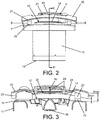
Figure 6 shows a cross-sectional perspective view of the upper end of the main body, the cover and the central cap. -
Figure 7 shows a perspective view of the cover seen from the lower face thereof. -
Figure 8A shows a schematic view of an extractor according to the prior state of the art with a front inlet for the intake of air. -
Figure 8A shows a schematic view of an extractor according to the prior state of the art with a lateral inlet (S) for the intake of air. -
Figure 8C is a schematic view of an extractor according to the invention with a lateral inlet for the intake of air and a front inlet for the intake of air. -
Figure 1 shows an embodiment of the air extractor for the ventilation of bathrooms, kitchens, or similar rooms in residential or commercial premises. - The air extractor comprises a main body (10), a cover (20) which is disposed over the main body (10) and a fan-motor assembly (30) which is accommodated inside the main body (10).
- The main body (10) has an upper end (11) wherein there is an opening (12) through which the fan-motor assembly (30) draws in air, and a lower end (13), opposite from the upper end (11), for the connection of the main body (10) with an air exhaust duct (not shown).
- The fan of the fan-motor assembly (30) is disposed in the opening (12) in the upper end (11) of the main body (10) in order to cause the intake of air through the opening (12).
- The opening (12) in the upper end (11) of the main body (10) has a grate (14) for protection against possible contacts of a user with the fan-motor assembly (30) if the cover (20) is removed with the extractor running.
- The operating electronics of the extractor are accommodated in the upper end (11) of the main body (10).
- The cover (20) has a central opening (21), the central opening (21) in the cover (20) being partially covered by a central cap (40).
- On the one hand, the cover (20) is separated from the opening (12) in the upper end (11) of the main body (10) by a first distance (D), such that a lateral inlet (S) for the intake of air is defined, while on the other hand, the central cap (40) is separated from the central opening (21) in the cover (20) by a second distance (d), such that a front inlet (F) for the intake of air is defined.
- With this configuration, a double inlet for the intake of air is established in the extractor. Thus, the fan of the fan-motor assembly (30) located in the opening (12) in the main body (10), on the one hand, draws in the air in order to lead it from the lateral inlet (S) for the intake of air to the opening (12) in the main body (10), and on the other hand, the fan also draws in the air in order to lead it from the front inlet (F) for the intake of air to the front opening (21) in the cover (20), and from there to the opening (12) in the main body (10), all the air drawn in being finally evacuated through the air exhaust duct which connects to the lower end (13) of the main body (10).
- The opening (12) in the main body (10) and the central opening (21) in the cover (20) are aligned, the central cap (40) being disposed aligned with both openings (12,21) in the main body (10) and the cover (20). In this manner, the central cap (40) is disposed preventing the front view of the grate (14) which covers the opening (12) in the main body, wherein dirt can accumulate.
- Thus, the imaginary axis which passes through the centre of the opening (12) in the main body (10) and the imaginary axis which passes through the centre of the central opening (21) in the cover (20) are coaxial, the imaginary axis which passes through the centre of the central cap (40) being equally aligned with the axes of both openings (12,21) in the main body (10) and in the cover (20).
- The central cap (40) has an outer dimension which is equal to, or smaller than, the inner dimension of the central opening (21) in the cover (20). In other words, the vertical projection of the central cap (40) is equal to or smaller than the vertical projection of the central opening (21). This enables the flow which enters through the front inlet (F) for the intake of air to follow a direction as rectilinear as possible to the opening (12) in the main body (10), as seen in the cross-sectional view of
figure 5 . - The extractor additionally comprises joining means (15,16,22,23) in order to establish a removable joint between the cover (20) and the upper end (11) of the main body (10). In this manner, the cover (20) can be disassembled from the main body (10) in order to facilitate cleaning tasks when necessary.
- Preferably, one (16,23) of the joining means (15,16,22,23) has a different shape than the other joining means (15,22) in order to establish an unequivocal assembly of the cover (20) on the main body (10).
- The different joining means (16,23) are additionally used to accommodate a light indicator of an operating state of the extractor.
- The central cap (40) is joined to the cover (20) through supports (24).
- The supports (24) have a laminar configuration with a thinner cross section which is disposed facing the front inlet (F) for the intake of air. In this manner, the supports (24) offer a minimum resistance to the passage of air, thus reducing the possible noise that may be generated.
- The supports (24) are disposed in positions diametrically opposite and equidistant from each other, each of the supports (24) being disposed in the centre of one of the sides of the cover (20).
- The cover (20) and the central cap (40) are manufactured in a single part which is preferably obtained by means of injection moulding of plastic material.
- The cover (20) has a domed area (25) on the periphery of the central opening (21) which enables the air flow which enters through the front inlet (F) for the intake of air to be directed.
- The shape and arrangement of the supports (24) are specially designed to optimise the injection moulding and enable a good flow of the plastic material during the moulding.
- Experimentally, it has been found that the air extraction conditions are improved for preferred dimensions of the first and second distances (D,d) which enable the double air inlet. Thus, the first separating distance (D) between the cover (20) and the opening (12) in the upper end (11) of the main body (10) is preferably comprised between 10 mm and 20 mm, and the second separating distance (d) between the central cap (40) and the central opening (21) in the cover (20) is preferably comprised between 5 mm and 10 mm.
- As represented by the arrows in the figures, the preferred dimensions of the first and second distances (D,d) indicated previously are dimensions measured vertically from one of the sides of the central cap (40) and of the cover (20), respectively.
- In any case, the separation between the cover (20) and the opening (12), and the separation between the central cap (40) and the central opening (21), can be a separation in a vertical direction, as shown in the exemplary embodiment of the figures, or it can be a separation in a horizontal direction, or a separation in an oblique direction, without this altering the concept of the invention of generating the double air inlet with the central cap (40) preventing the existence of visible portions of the extractor wherein dirt accumulates.
- Preferably, the cover (20) has a concave shape such that the first distance (D) by which the cover (20) is separated from the opening (12) in the main body (10) is variable along the cover (20), the first distance (D) having a central area with a maximum separation (Dmax) between the cover (20) and the opening (12) in the main body (10) and end areas with a minimum separation (Dmin) between the cover (20) and the opening (12) in the main body (10).
- Preferably, the central cap (40) also has a concave shape, such that the second distance (d) by which the central cap (40) is separated from the central opening (21) in the cover (20) is also variable along the central cap (40). Thus, the second distance (d) also has a central area with a maximum separation between the central cap (40) and the central opening (21) in the cover (20) and end areas with a minimum separation between the central cap (40) and the central opening (21) in the cover (20).
- As seen in the exemplary embodiment shown in
figures 1 to 7 , the main body (10) has a preferably cylindrical configuration, while the upper end (11) of the main body (10), the cover (20) and the central opening (21) thereof, as well as the central cap (40), have a preferably square configuration. In any case, the square configuration is not limiting, the central cap (40) and/or the cover (20) being able to have other types of shapes without altering the concept of the invention, such as, for example, another polygonal shape with at least three sides, or a circular shape. - According to said preferred exemplary embodiment, the upper end (11) of the main body (10), the cover (20), the central opening (21) thereof, and the central cap (40) have four sides respectively, the sides of each of said portions (11,20,21,40) of the extractor being approximately parallel to each other.
- As seen in detail in
figures 3 ,5 and7 , there are four supports (24) which join the central cap (40) to the cover (20), each of the supports (24) being disposed in the centre of one of the sides of the cover (20), and the thinner cross section of the laminar configuration of the support (24) being disposed facing the front inlet (F) for the intake of air. - As shown in detail in
figures 3 and5 , the joining means (15,16,22,23) between the cover (20) and the main body (10) comprise projections (15,16) disposed at the upper end (11) of the main body (10) and housings (22,23) disposed in the inner face of the cover (20). - As shown in
figure 5 , between the projections (15,16) and the housings (22,23) a stepped area is established in order to establish an insertion stop for the projections (15,16) in the housings (22,23). - Specifically, and as shown in the exemplary embodiment shown in the figures, the removable joining means comprise three projections (15) and three housings (22) with one shape, and one projection (16) and one housing (23) with a different shape in order to enable the unequivocal assembly.
- As shown in
figure 5 , the projection (16) and the housing (23) with the other different shape are open on the inside thereof in order to enable the passage of the light guide of the light indicator. - As shown in
figures 1 and2 , each of the four sides of the cover (20) has a radius of curvature with a concave shape, such that the first distance (D) by which each side of the cover (20) is separated from the main body (10) is variable along the side of the cover (20). Each side of the cover (20) has the maximum separation (Dmax) in the centre of said side and has the minimum separation (Dmin) at the ends of said side. The radius of curvature of the sides of the cover (20) enables the maximum separation to be originated in a position close to the opening (12) in the main body (10) through which the air is drawn in, while the minimum separation is originated in the positions furthest from the opening (12). - Preferably the radius of curvature of each side of the cover (20) is between 300 mm and 450 mm.
- Also as shown in
figures 1 and2 , each of the four sides of the central cap (40) has a radius of curvature with a concave shape, such that the second distance (d) by which each side of the central cap (40) is separated from the cover (20) is variable along the side of the central cap (40). Each side of the central cap (40) has the maximum separation in the centre of said side and has the minimum separation at the ends of said side. As previously described, the radius of curvature of the sides of the central cap (40) enables the maximum separation to be originated in a position close to the opening (12) in the main body (10) through which the air is drawn in, while the minimum separation is originated in the positions furthest from the opening (12). For the sake of clarity in the figures, the references with respect to the maximum and minimum separations between the central cap (40) and the cover (20) are not shown in the figures. - Preferably the radius of curvature of each side of the central cap (40) is between 300 mm and 450 mm.
- Even more preferably, the radius of curvature of each side of the cover (20) and the central cap (40) is the same, such that a continuous curvature is maintained between the cover (20) and the central cap (40) which improves the aesthetics of the extractor.
-
Figures 8A, 8B and 8C show a comparison of the direction followed by the flow of the extracted air in three air extractors.Figure 8A shows an extractor according to the state of the art with a front inlet (F) for the intake of air,figure 8B shows an extractor according to the state of the art with a lateral inlet (S) for the intake of air, andfigure 8C shows an extractor according to the invention with a lateral inlet (S) for the intake of air and a front inlet (F) for the intake of air. - The extractor in
figure 8A has a front cover which has holes and the air is drawn in according to a direction coaxial with the shaft of the fan, passing through a protective grate, while the extractor offigure 8B has a smooth front cover which does not have any holes, and in this case the air is drawn in laterally, through the four sides of the extractor. - The extractor of
figure 8A has the drawback that it is not very aesthetic since it leaves the grate and the fan exposed; furthermore, the dirt which tends to adhere in them is difficult to remove due to the irregular shapes of both of them. However, it has the advantage that the air flow is continuous, without changes in direction, which results in high aerodynamic efficiency. - The extractor of
figure 8B has the advantage that it does not get dirty and if that happens, since the front cover is smooth, it is very easy to clean. However, it has the drawback of lower performance than the extractor offigure 8A . Indeed, the four air flows enter through the four sides in a direction perpendicular to the outlet direction, which forces the air to make a 90° turn, furthermore, when the four flows enter in opposite directions two by two, they collide with each other inside the extractor just below the cover producing turbulence, greater noise and a decrease in the flow and pressure performance of the extractor due to that impact and these turbulences. - The extractor of the invention (see
figure 8C ) combines the advantages of the extractors offigures 8A and 8B , without having any of the drawbacks thereof. The cover (20) has the central opening (21) partially blocked by the central cap (40) such that air passages are created between both of them (in the case of the rectangular figures) with dimensions calculated in order to originate the front air flow (F) (dashed lines) with an air velocity sufficient to help the four lateral air flows (S) (solid line) make the 90° turn, thus preventing the impact between them. The consequence of having this front flow (F) "orienting" the lateral flows (S) is that the aerodynamic performance of the extractor proposed by the invention is similar to the performance of the extractor offigure 8A , while the trend to not get dirty and the ease of cleaning are similar to those of the extractor offigure 8B .
Claims (14)
- A double-inlet air extractor characterised in that it comprises:• a main body (10) having an upper end (11) with an opening (12) for the intake of air,• a cover (20) disposed over the upper end (11) of the main body (10), and• a fan-motor assembly (30) accommodated in the main body (10), the fan of the fan-motor assembly (30) being disposed in the opening (12) for the intake of air from the main body (10), and wherein:∘ the cover (20) is separated from the opening (12) in the upper end (11) of the main body (10) by a first distance (D), such that between the cover (20) and the opening (12) in the upper end (11) of the main body (10) a lateral inlet (S) for the intake of air is defined for leading the air from the lateral inlet (S) to the opening (12) in the upper end (11) of the main body (10), and wherein∘ the cover (20) has a central opening (21) that is partially covered by a central cap (40), the central cap (40) being separated from the central opening (21) in the cover (20) by a second distance (d), such that a front inlet (F) for the intake of air is defined between the central cap (40) and the central opening (21) in the cover (20) for leading the air from the front inlet (F) to the opening (12) in the main body (10).
- The extractor according to the preceding claim characterised in that the central cap (40) has an outer dimension which is equal to, or smaller than, the inner dimension of the central opening (21) in the cover (20).
- The extractor according to the preceding claim, characterised in that it additionally comprises joining means (15,16,22,23) in order to establish a removable joint between the cover (20) and the upper end (11) of the main body (10).
- The extractor according to the preceding claim characterised in that one (16,23) of the joining means (15,16,22,23) has a different shape than the other joining means (15,22) in order to establish an unequivocal assembly of the cover (20) on the main body (10).
- The extractor according to the preceding claim, characterised in that the joining means (16,23) having the different shape accommodate a light indicator of an operating state of the extractor.
- The extractor according to any one of the preceding claims, characterised in that the central cap (40) is joined to the cover (20) through supports (24).
- The extractor according to the preceding claim, characterised in that the supports (24) have a laminar configuration with a thinner cross section which is disposed facing the front inlet (F) for the intake of air.
- The extractor according to claim 6, or 7, characterised in that the supports (24) are disposed in positions diametrically opposite and equidistant from each other, each of the supports (24) being disposed in the centre of one of the sides of the cover (20).
- The extractor according to any one of the preceding claims, characterised in that the opening (12) in the main body (10) and the central opening (21) in the cover (20) are aligned, the central cap (40) being disposed aligned with both openings (12,21).
- The extractor according to any one of the preceding claims, characterised in that the cover (20) has a domed area (25) on the periphery of the central opening (21).
- The extractor according to any one of the preceding claims, characterised in that the first separating distance (D) between the cover (20) and the opening (12) in the upper end (11) of the main body (10) is comprised between 10 mm and 20 mm.
- The extractor according to any one of the preceding claims, characterised in that the second separating distance (d) between the central cap (40) and the central opening (21) in the cover (20) is comprised between 5 mm and 10 mm.
- The extractor according to any one of the preceding claims, characterised in that the cover (20) has a concave shape, such that the first distance (D) has a central area with a maximum distance (Dmax) between the cover (20) and the opening (12) in the main body (10) and end areas with a minimum separation (Dmin) between the cover (20) and the opening (12) in the main body (10).
- The extractor according to any one of the preceding claims, characterised in that the central cap (40) has a concave shape, such that the second distance (d) has a central area with a maximum separation between the central cap (40) and the central opening (21) in the cover (20) and end areas with a minimum separation between the central cap (40) and the central opening (21) in the cover (20).
Applications Claiming Priority (2)
| Application Number | Priority Date | Filing Date | Title |
|---|---|---|---|
| ES201831268A ES2769475B2 (en) | 2018-12-21 | 2018-12-21 | DOUBLE AIR INLET EXTRACTOR |
| PCT/ES2019/070793 WO2020128123A1 (en) | 2018-12-21 | 2019-11-20 | Double-inlet air extractor |
Publications (2)
| Publication Number | Publication Date |
|---|---|
| EP3901467A1 true EP3901467A1 (en) | 2021-10-27 |
| EP3901467A4 EP3901467A4 (en) | 2022-09-14 |
Family
ID=71100242
Family Applications (1)
| Application Number | Title | Priority Date | Filing Date |
|---|---|---|---|
| EP19899590.4A Pending EP3901467A4 (en) | 2018-12-21 | 2019-11-20 | Double-inlet air extractor |
Country Status (5)
| Country | Link |
|---|---|
| EP (1) | EP3901467A4 (en) |
| AU (1) | AU2019410914A1 (en) |
| ES (1) | ES2769475B2 (en) |
| UA (1) | UA127463C2 (en) |
| WO (1) | WO2020128123A1 (en) |
Families Citing this family (1)
| Publication number | Priority date | Publication date | Assignee | Title |
|---|---|---|---|---|
| CN114001038B (en) * | 2021-12-22 | 2023-11-10 | 浙江上清风机有限公司 | Fan with double air inlets |
Family Cites Families (9)
| Publication number | Priority date | Publication date | Assignee | Title |
|---|---|---|---|---|
| ES282840Y (en) * | 1984-11-09 | 1985-12-01 | Verdaguer Busquets Jose | AIR EXTRACTOR |
| ES2251878B1 (en) | 2004-10-26 | 2007-02-16 | SOLER & PALAU, S.A. | AXIAL FLOW AIR EXTRACTOR FOR BATHROOMS AND SIMILAR. |
| AU2006246463A1 (en) * | 2005-11-30 | 2007-06-14 | Greenwood Air Management Limited | Vibration damped electric fan |
| ES2292344B1 (en) | 2006-04-19 | 2009-05-05 | SOLER & PALAU, S.A. | SHOCK ABSORBER HOUSING FOR THE MOTOR OF A TOILET AND BATHROOM EXTRACTOR. |
| ES2385592B1 (en) * | 2010-12-30 | 2013-04-15 | Soler & Palau Research, S.L. | CENTRIFUGAL AIR EXTRACTOR FOR BATHROOMS. |
| CN202391766U (en) * | 2011-12-09 | 2012-08-22 | 中山市欧帝尔电器照明有限公司 | Novel multifunctional exhaust fan |
| GB2511518B (en) * | 2013-03-05 | 2018-11-28 | Nuaire Ltd | A dual inlet extract fan assembly |
| CN104213619B (en) * | 2014-07-21 | 2016-03-02 | 博麟水电材料有限公司 | Bath lavatory ventilation fan |
| GB201704403D0 (en) * | 2017-03-20 | 2017-05-03 | Gibbons Martin | Extractor |
-
2018
- 2018-12-21 ES ES201831268A patent/ES2769475B2/en active Active
-
2019
- 2019-11-20 AU AU2019410914A patent/AU2019410914A1/en not_active Abandoned
- 2019-11-20 EP EP19899590.4A patent/EP3901467A4/en active Pending
- 2019-11-20 UA UAA202104241A patent/UA127463C2/en unknown
- 2019-11-20 WO PCT/ES2019/070793 patent/WO2020128123A1/en unknown
Also Published As
| Publication number | Publication date |
|---|---|
| ES2769475A1 (en) | 2020-06-25 |
| WO2020128123A1 (en) | 2020-06-25 |
| UA127463C2 (en) | 2023-08-30 |
| AU2019410914A1 (en) | 2021-07-01 |
| EP3901467A4 (en) | 2022-09-14 |
| ES2769475B2 (en) | 2021-10-21 |
Similar Documents
| Publication | Publication Date | Title |
|---|---|---|
| TWI575201B (en) | Air-exchanging device and indoor box thereof | |
| EP3704385B1 (en) | Fan | |
| EP3550212A1 (en) | Cookware and exhaust device | |
| US9366450B2 (en) | Air adjuster | |
| EP3901467A1 (en) | Double-inlet air extractor | |
| CN108592131A (en) | Range hood | |
| CN107990392B (en) | Fume exhauster | |
| WO2016129379A1 (en) | Air conditioner | |
| KR102217013B1 (en) | Indoor unit of ceiling type air-conditioner | |
| CN109268899A (en) | A kind of range hood | |
| US6913014B2 (en) | Smoke guide structure for kitchen hood | |
| RU2775735C1 (en) | Exhaust fan with double inlet | |
| JP5609498B2 (en) | Air conditioner indoor unit | |
| KR101995119B1 (en) | window-mounted air purifier | |
| JP5928246B2 (en) | Air conditioner | |
| KR102343464B1 (en) | Indoor unit of ceiling type air-conditioner | |
| KR100751121B1 (en) | Indoor unit for air-conditioner | |
| CN108870483B (en) | Cleaning-free range hood | |
| JP5338274B2 (en) | Air conditioner | |
| KR102024566B1 (en) | Local ventilation equipment | |
| WO2015166947A1 (en) | Exhaust device | |
| KR102592441B1 (en) | Blower for Vehicle | |
| JP2008075947A (en) | Ceiling embedded air conditioner | |
| JP2002013772A (en) | Air supply and exhaust device | |
| JP5144948B2 (en) | Kitchen exhaust grill |
Legal Events
| Date | Code | Title | Description |
|---|---|---|---|
| STAA | Information on the status of an ep patent application or granted ep patent |
Free format text: STATUS: THE INTERNATIONAL PUBLICATION HAS BEEN MADE |
|
| PUAI | Public reference made under article 153(3) epc to a published international application that has entered the european phase |
Free format text: ORIGINAL CODE: 0009012 |
|
| STAA | Information on the status of an ep patent application or granted ep patent |
Free format text: STATUS: REQUEST FOR EXAMINATION WAS MADE |
|
| 17P | Request for examination filed |
Effective date: 20210720 |
|
| AK | Designated contracting states |
Kind code of ref document: A1 Designated state(s): AL AT BE BG CH CY CZ DE DK EE ES FI FR GB GR HR HU IE IS IT LI LT LU LV MC MK MT NL NO PL PT RO RS SE SI SK SM TR |
|
| DAV | Request for validation of the european patent (deleted) | ||
| DAX | Request for extension of the european patent (deleted) | ||
| A4 | Supplementary search report drawn up and despatched |
Effective date: 20220812 |
|
| RIC1 | Information provided on ipc code assigned before grant |
Ipc: F04D 29/70 20060101ALI20220808BHEP Ipc: F04D 29/42 20060101ALI20220808BHEP Ipc: F04D 29/54 20060101ALI20220808BHEP Ipc: F04D 25/12 20060101AFI20220808BHEP |
|
| P01 | Opt-out of the competence of the unified patent court (upc) registered |
Effective date: 20230519 |
|
| STAA | Information on the status of an ep patent application or granted ep patent |
Free format text: STATUS: EXAMINATION IS IN PROGRESS |
|
| 17Q | First examination report despatched |
Effective date: 20240321 |