EP3901462A1 - Compressor - Google Patents
Compressor Download PDFInfo
- Publication number
- EP3901462A1 EP3901462A1 EP21168235.6A EP21168235A EP3901462A1 EP 3901462 A1 EP3901462 A1 EP 3901462A1 EP 21168235 A EP21168235 A EP 21168235A EP 3901462 A1 EP3901462 A1 EP 3901462A1
- Authority
- EP
- European Patent Office
- Prior art keywords
- oil
- channel
- orbiting
- oil channel
- outlet
- Prior art date
- Legal status (The legal status is an assumption and is not a legal conclusion. Google has not performed a legal analysis and makes no representation as to the accuracy of the status listed.)
- Granted
Links
Images


Classifications
-
- F—MECHANICAL ENGINEERING; LIGHTING; HEATING; WEAPONS; BLASTING
- F04—POSITIVE - DISPLACEMENT MACHINES FOR LIQUIDS; PUMPS FOR LIQUIDS OR ELASTIC FLUIDS
- F04C—ROTARY-PISTON, OR OSCILLATING-PISTON, POSITIVE-DISPLACEMENT MACHINES FOR LIQUIDS; ROTARY-PISTON, OR OSCILLATING-PISTON, POSITIVE-DISPLACEMENT PUMPS
- F04C18/00—Rotary-piston pumps specially adapted for elastic fluids
- F04C18/02—Rotary-piston pumps specially adapted for elastic fluids of arcuate-engagement type, i.e. with circular translatory movement of co-operating members, each member having the same number of teeth or tooth-equivalents
- F04C18/0207—Rotary-piston pumps specially adapted for elastic fluids of arcuate-engagement type, i.e. with circular translatory movement of co-operating members, each member having the same number of teeth or tooth-equivalents both members having co-operating elements in spiral form
- F04C18/0246—Details concerning the involute wraps or their base, e.g. geometry
- F04C18/0253—Details concerning the base
-
- F—MECHANICAL ENGINEERING; LIGHTING; HEATING; WEAPONS; BLASTING
- F04—POSITIVE - DISPLACEMENT MACHINES FOR LIQUIDS; PUMPS FOR LIQUIDS OR ELASTIC FLUIDS
- F04C—ROTARY-PISTON, OR OSCILLATING-PISTON, POSITIVE-DISPLACEMENT MACHINES FOR LIQUIDS; ROTARY-PISTON, OR OSCILLATING-PISTON, POSITIVE-DISPLACEMENT PUMPS
- F04C18/00—Rotary-piston pumps specially adapted for elastic fluids
- F04C18/02—Rotary-piston pumps specially adapted for elastic fluids of arcuate-engagement type, i.e. with circular translatory movement of co-operating members, each member having the same number of teeth or tooth-equivalents
- F04C18/0207—Rotary-piston pumps specially adapted for elastic fluids of arcuate-engagement type, i.e. with circular translatory movement of co-operating members, each member having the same number of teeth or tooth-equivalents both members having co-operating elements in spiral form
- F04C18/0215—Rotary-piston pumps specially adapted for elastic fluids of arcuate-engagement type, i.e. with circular translatory movement of co-operating members, each member having the same number of teeth or tooth-equivalents both members having co-operating elements in spiral form where only one member is moving
-
- F—MECHANICAL ENGINEERING; LIGHTING; HEATING; WEAPONS; BLASTING
- F04—POSITIVE - DISPLACEMENT MACHINES FOR LIQUIDS; PUMPS FOR LIQUIDS OR ELASTIC FLUIDS
- F04C—ROTARY-PISTON, OR OSCILLATING-PISTON, POSITIVE-DISPLACEMENT MACHINES FOR LIQUIDS; ROTARY-PISTON, OR OSCILLATING-PISTON, POSITIVE-DISPLACEMENT PUMPS
- F04C18/00—Rotary-piston pumps specially adapted for elastic fluids
- F04C18/02—Rotary-piston pumps specially adapted for elastic fluids of arcuate-engagement type, i.e. with circular translatory movement of co-operating members, each member having the same number of teeth or tooth-equivalents
- F04C18/0207—Rotary-piston pumps specially adapted for elastic fluids of arcuate-engagement type, i.e. with circular translatory movement of co-operating members, each member having the same number of teeth or tooth-equivalents both members having co-operating elements in spiral form
- F04C18/0246—Details concerning the involute wraps or their base, e.g. geometry
- F04C18/0253—Details concerning the base
- F04C18/0261—Details of the ports, e.g. location, number, geometry
-
- F—MECHANICAL ENGINEERING; LIGHTING; HEATING; WEAPONS; BLASTING
- F04—POSITIVE - DISPLACEMENT MACHINES FOR LIQUIDS; PUMPS FOR LIQUIDS OR ELASTIC FLUIDS
- F04C—ROTARY-PISTON, OR OSCILLATING-PISTON, POSITIVE-DISPLACEMENT MACHINES FOR LIQUIDS; ROTARY-PISTON, OR OSCILLATING-PISTON, POSITIVE-DISPLACEMENT PUMPS
- F04C18/00—Rotary-piston pumps specially adapted for elastic fluids
- F04C18/02—Rotary-piston pumps specially adapted for elastic fluids of arcuate-engagement type, i.e. with circular translatory movement of co-operating members, each member having the same number of teeth or tooth-equivalents
- F04C18/0207—Rotary-piston pumps specially adapted for elastic fluids of arcuate-engagement type, i.e. with circular translatory movement of co-operating members, each member having the same number of teeth or tooth-equivalents both members having co-operating elements in spiral form
- F04C18/0246—Details concerning the involute wraps or their base, e.g. geometry
- F04C18/0269—Details concerning the involute wraps
- F04C18/0292—Ports or channels located in the wrap
-
- F—MECHANICAL ENGINEERING; LIGHTING; HEATING; WEAPONS; BLASTING
- F04—POSITIVE - DISPLACEMENT MACHINES FOR LIQUIDS; PUMPS FOR LIQUIDS OR ELASTIC FLUIDS
- F04C—ROTARY-PISTON, OR OSCILLATING-PISTON, POSITIVE-DISPLACEMENT MACHINES FOR LIQUIDS; ROTARY-PISTON, OR OSCILLATING-PISTON, POSITIVE-DISPLACEMENT PUMPS
- F04C29/00—Component parts, details or accessories of pumps or pumping installations, not provided for in groups F04C18/00 - F04C28/00
- F04C29/02—Lubrication; Lubricant separation
-
- F—MECHANICAL ENGINEERING; LIGHTING; HEATING; WEAPONS; BLASTING
- F04—POSITIVE - DISPLACEMENT MACHINES FOR LIQUIDS; PUMPS FOR LIQUIDS OR ELASTIC FLUIDS
- F04C—ROTARY-PISTON, OR OSCILLATING-PISTON, POSITIVE-DISPLACEMENT MACHINES FOR LIQUIDS; ROTARY-PISTON, OR OSCILLATING-PISTON, POSITIVE-DISPLACEMENT PUMPS
- F04C29/00—Component parts, details or accessories of pumps or pumping installations, not provided for in groups F04C18/00 - F04C28/00
- F04C29/02—Lubrication; Lubricant separation
- F04C29/021—Control systems for the circulation of the lubricant
-
- F—MECHANICAL ENGINEERING; LIGHTING; HEATING; WEAPONS; BLASTING
- F04—POSITIVE - DISPLACEMENT MACHINES FOR LIQUIDS; PUMPS FOR LIQUIDS OR ELASTIC FLUIDS
- F04C—ROTARY-PISTON, OR OSCILLATING-PISTON, POSITIVE-DISPLACEMENT MACHINES FOR LIQUIDS; ROTARY-PISTON, OR OSCILLATING-PISTON, POSITIVE-DISPLACEMENT PUMPS
- F04C29/00—Component parts, details or accessories of pumps or pumping installations, not provided for in groups F04C18/00 - F04C28/00
- F04C29/02—Lubrication; Lubricant separation
- F04C29/023—Lubricant distribution through a hollow driving shaft
-
- F—MECHANICAL ENGINEERING; LIGHTING; HEATING; WEAPONS; BLASTING
- F04—POSITIVE - DISPLACEMENT MACHINES FOR LIQUIDS; PUMPS FOR LIQUIDS OR ELASTIC FLUIDS
- F04C—ROTARY-PISTON, OR OSCILLATING-PISTON, POSITIVE-DISPLACEMENT MACHINES FOR LIQUIDS; ROTARY-PISTON, OR OSCILLATING-PISTON, POSITIVE-DISPLACEMENT PUMPS
- F04C29/00—Component parts, details or accessories of pumps or pumping installations, not provided for in groups F04C18/00 - F04C28/00
- F04C29/12—Arrangements for admission or discharge of the working fluid, e.g. constructional features of the inlet or outlet
-
- F—MECHANICAL ENGINEERING; LIGHTING; HEATING; WEAPONS; BLASTING
- F04—POSITIVE - DISPLACEMENT MACHINES FOR LIQUIDS; PUMPS FOR LIQUIDS OR ELASTIC FLUIDS
- F04C—ROTARY-PISTON, OR OSCILLATING-PISTON, POSITIVE-DISPLACEMENT MACHINES FOR LIQUIDS; ROTARY-PISTON, OR OSCILLATING-PISTON, POSITIVE-DISPLACEMENT PUMPS
- F04C2210/00—Fluid
- F04C2210/26—Refrigerants with particular properties, e.g. HFC-134a
-
- F—MECHANICAL ENGINEERING; LIGHTING; HEATING; WEAPONS; BLASTING
- F04—POSITIVE - DISPLACEMENT MACHINES FOR LIQUIDS; PUMPS FOR LIQUIDS OR ELASTIC FLUIDS
- F04C—ROTARY-PISTON, OR OSCILLATING-PISTON, POSITIVE-DISPLACEMENT MACHINES FOR LIQUIDS; ROTARY-PISTON, OR OSCILLATING-PISTON, POSITIVE-DISPLACEMENT PUMPS
- F04C2240/00—Components
- F04C2240/20—Rotors
-
- F—MECHANICAL ENGINEERING; LIGHTING; HEATING; WEAPONS; BLASTING
- F04—POSITIVE - DISPLACEMENT MACHINES FOR LIQUIDS; PUMPS FOR LIQUIDS OR ELASTIC FLUIDS
- F04C—ROTARY-PISTON, OR OSCILLATING-PISTON, POSITIVE-DISPLACEMENT MACHINES FOR LIQUIDS; ROTARY-PISTON, OR OSCILLATING-PISTON, POSITIVE-DISPLACEMENT PUMPS
- F04C2240/00—Components
- F04C2240/30—Casings or housings
-
- F—MECHANICAL ENGINEERING; LIGHTING; HEATING; WEAPONS; BLASTING
- F04—POSITIVE - DISPLACEMENT MACHINES FOR LIQUIDS; PUMPS FOR LIQUIDS OR ELASTIC FLUIDS
- F04C—ROTARY-PISTON, OR OSCILLATING-PISTON, POSITIVE-DISPLACEMENT MACHINES FOR LIQUIDS; ROTARY-PISTON, OR OSCILLATING-PISTON, POSITIVE-DISPLACEMENT PUMPS
- F04C2240/00—Components
- F04C2240/60—Shafts
- F04C2240/603—Shafts with internal channels for fluid distribution, e.g. hollow shaft
-
- F—MECHANICAL ENGINEERING; LIGHTING; HEATING; WEAPONS; BLASTING
- F04—POSITIVE - DISPLACEMENT MACHINES FOR LIQUIDS; PUMPS FOR LIQUIDS OR ELASTIC FLUIDS
- F04C—ROTARY-PISTON, OR OSCILLATING-PISTON, POSITIVE-DISPLACEMENT MACHINES FOR LIQUIDS; ROTARY-PISTON, OR OSCILLATING-PISTON, POSITIVE-DISPLACEMENT PUMPS
- F04C2240/00—Components
- F04C2240/80—Other components
- F04C2240/809—Lubricant sump
-
- F—MECHANICAL ENGINEERING; LIGHTING; HEATING; WEAPONS; BLASTING
- F04—POSITIVE - DISPLACEMENT MACHINES FOR LIQUIDS; PUMPS FOR LIQUIDS OR ELASTIC FLUIDS
- F04C—ROTARY-PISTON, OR OSCILLATING-PISTON, POSITIVE-DISPLACEMENT MACHINES FOR LIQUIDS; ROTARY-PISTON, OR OSCILLATING-PISTON, POSITIVE-DISPLACEMENT PUMPS
- F04C2250/00—Geometry
- F04C2250/10—Geometry of the inlet or outlet
- F04C2250/102—Geometry of the inlet or outlet of the outlet
-
- F—MECHANICAL ENGINEERING; LIGHTING; HEATING; WEAPONS; BLASTING
- F04—POSITIVE - DISPLACEMENT MACHINES FOR LIQUIDS; PUMPS FOR LIQUIDS OR ELASTIC FLUIDS
- F04C—ROTARY-PISTON, OR OSCILLATING-PISTON, POSITIVE-DISPLACEMENT MACHINES FOR LIQUIDS; ROTARY-PISTON, OR OSCILLATING-PISTON, POSITIVE-DISPLACEMENT PUMPS
- F04C23/00—Combinations of two or more pumps, each being of rotary-piston or oscillating-piston type, specially adapted for elastic fluids; Pumping installations specially adapted for elastic fluids; Multi-stage pumps specially adapted for elastic fluids
- F04C23/008—Hermetic pumps
-
- F—MECHANICAL ENGINEERING; LIGHTING; HEATING; WEAPONS; BLASTING
- F05—INDEXING SCHEMES RELATING TO ENGINES OR PUMPS IN VARIOUS SUBCLASSES OF CLASSES F01-F04
- F05B—INDEXING SCHEME RELATING TO WIND, SPRING, WEIGHT, INERTIA OR LIKE MOTORS, TO MACHINES OR ENGINES FOR LIQUIDS COVERED BY SUBCLASSES F03B, F03D AND F03G
- F05B2210/00—Working fluid
- F05B2210/10—Kind or type
- F05B2210/14—Refrigerants with particular properties, e.g. HFC-134a
-
- F—MECHANICAL ENGINEERING; LIGHTING; HEATING; WEAPONS; BLASTING
- F05—INDEXING SCHEMES RELATING TO ENGINES OR PUMPS IN VARIOUS SUBCLASSES OF CLASSES F01-F04
- F05B—INDEXING SCHEME RELATING TO WIND, SPRING, WEIGHT, INERTIA OR LIKE MOTORS, TO MACHINES OR ENGINES FOR LIQUIDS COVERED BY SUBCLASSES F03B, F03D AND F03G
- F05B2240/00—Components
- F05B2240/20—Rotors
-
- F—MECHANICAL ENGINEERING; LIGHTING; HEATING; WEAPONS; BLASTING
- F05—INDEXING SCHEMES RELATING TO ENGINES OR PUMPS IN VARIOUS SUBCLASSES OF CLASSES F01-F04
- F05B—INDEXING SCHEME RELATING TO WIND, SPRING, WEIGHT, INERTIA OR LIKE MOTORS, TO MACHINES OR ENGINES FOR LIQUIDS COVERED BY SUBCLASSES F03B, F03D AND F03G
- F05B2260/00—Function
- F05B2260/98—Lubrication
Definitions
- the present disclosure relates to a compressor. More specifically, the present disclosure relates to a scroll type compressor having an oil feeding channel capable of supplying oil to a compressing assembly in which refrigerant is compressed.
- a compressor is an apparatus applied to a refrigeration cycle such as a refrigerator or an air conditioner, which compresses refrigerant to provide work necessary to generate heat exchange in the refrigeration cycle.
- the compressors may be classified into a reciprocating type compressor, a rotary type compressor, and a scroll type compressor based on a scheme in which the refrigerant is compressed.
- the scroll type compressor while an orbiting scroll is engaged with a fixed scroll fixed in an internal space of a sealed container, the orbiting scroll orbits, thereby to define a compression chamber between a fixed wrap of the fixed scroll and an orbiting wrap of the orbiting scroll.
- the scroll type compressor may obtain a relatively high compression ratio because the refrigerant is continuously compressed using the scrolls engaged with each other, and may obtain a stable torque because suction, compression, and discharge of the refrigerant proceed smoothly. For this reason, the scroll type compressor is widely used for compressing the refrigerant in the air conditioner and the like.
- a conventional scroll type compressor includes a casing forming an outer shape of the compressor and having a discharger for discharging refrigerant, a compression assembly fixed to the casing to compress the refrigerant, and a driver fixed to the casing to drive the compression assembly, wherein the compression assembly and the driver are coupled to a rotatable shaft that is coupled to the driver and rotates.
- the compression assembly includes a fixed scroll fixed to the casing and having a fixed wrap, and an orbiting scroll including an orbiting wrap orbiting in a state of being engaged with the fixed wrap via the rotatable shaft.
- the rotatable shaft is eccentric
- the orbiting scroll is fixed to the eccentric rotatable shaft and orbits.
- the orbiting scroll orbits along the fixed scroll to compress the refrigerant.
- the compression assembly is generally disposed below the discharger, and the driver is generally disposed below the compression assembly. Further, the rotatable shaft generally has one end coupled to the compression assembly and the other end passing through the driver.
- the conventional scroll type compressor has difficulty in supplying oil into the compression assembly because the compression assembly is disposed above the driver and is closer to the discharger. Further, an additional lower frame under the driver is required to separately support the rotatable shaft connected to the compression assembly. Further, in the conventional scroll compressor, because action points of a gas force generated via the compression of the refrigerant and a reaction force supporting the gas force do not coincide with each other within the compression assembly, the orbiting scroll tilts, resulting in a problem of lowering efficiency and reliability thereof.
- the shaft-through scroll type compressor has the advantage of smooth oil supply since the compressing assembly 300 is closer to an oil storage space than the driver is. Further, since the compressing assembly 300 itself supports the rotatable shaft extending from the driver, a structure for separately supporting the rotatable shaft may be omitted, thereby simplifying a structure thereof.
- the rotatable shaft when the rotatable shaft extends through an entirety of the compressing assembly 300, the rotatable shaft supports vibration or pressure generated in the compressing assembly 300 in a longitudinal direction, thereby improving the reliability of the compressor.
- FIG. 1 shows a detailed structure of the compressing assembly of the conventional compressor.
- the compressing assembly may include an orbiting scroll 330 that rotatably accommodates a rotatable shaft 230, and a fixed scroll 320 engaging with the orbiting scroll to form a compression chamber in which the refrigerant is compressed, and a main frame 310 mounted on the fixed scroll 320 to accommodate the orbiting scroll 330 therein.
- the rotatable shaft 230 may include an eccentric shaft 232 having an diameter expanding in a biased manner as accommodated in the orbiting scroll 330. Accordingly, as the rotatable shaft 230 rotates, the eccentric shaft 232 presses the orbiting scroll 330 along a circumference of the fixed scroll 320 to continuously compress the refrigerant flowing along the orbiting scroll 330 and the fixed scroll 320.
- the conventional compressor may further include an oil feeding channel passing through the rotatable shaft 230 and the main frame 310 and the fixed scroll 320.
- the oil feeding channel I extends to an area facing the orbiting wrap 333 of the orbiting scroll 330 to deliver the oil to the compression chamber.
- an outlet of the oil feeding channel I may be disposed at one of an inner channel A (i.e. an inner compression chamber A) spaced from an inner face of the orbiting wrap 333 or an outer channel B (i.e. an outer compression chamber B) spaced from an outer face of the orbiting wrap 333.
- the inner face of the orbiting wrap 333 means a radially inner surface of the orbiting wrap 333
- the outer face of the orbiting wrap 333 means a radially outer surface of the orbiting wrap 333.
- the inner face and the outer face of the orbiting wrap 333 are opposite to each other with respect to a center line of the orbiting wrap 333 forming a scroll shape.
- the outlet of the oil feeding channel I may be blocked by the orbiting wrap 333 as the orbiting wrap 333 moves according to the rotation of the eccentric shaft 232.
- the oil feeding channel I may be closed such that the oil feeding is stopped.
- FIG. 1 shows an oil feeding pressure according to an angle at which the orbiting wrap 333 extends in a direction in which the orbiting wrap 333 accommodates the rotatable shaft 230 relative to a refrigerant intake hole of the fixed scroll through which the refrigerant is sucked.
- a graph (b) in FIG. 1 it may be seen that oil is supplied to the outer channel B in a section of 0 to 30 degrees and a section of 270 degrees to 360 degrees, while the oil is supplied to the inner channel A in a section of 70 to 220 degrees.
- the oil feeding channel I is closed by the orbiting wrap 333 so that the oil feeding is stopped in a section between 30 degrees and 70 degrees and a section between 220 degrees and 270 degrees.
- the conventional compressor has a problem in that the oil feeding stops in the specific section, so that the oil cannot be fed to the entire compressor. Further, there is a problem in that the reliability of the compressor cannot be guaranteed due to structural limitations such as severe wear and damage in the specific section.
- a purpose of the present disclosure is to provide a scroll type compressor in which both of outlets for feeding oil into a region between the orbiting scroll and the fixed scroll may be prevented from being blocked at the same time even when the orbiting scroll moves by the rotatable shaft.
- a purpose of the present disclosure is to provide a scroll type compressor in which a plurality of oil channels to supply oil are defined to prevents oil feeding from being interrupted.
- a purpose of the present disclosure is to provide a scroll type compressor in which all of a plurality of oil channels for supplying oil may be prevented from being blocked no matter where the orbiting scroll is positioned.
- a purpose of the present disclosure is to provide a scroll type compressor having oil feeding channels for feeding the oil to the inner and outer faces of the orbiting wrap of the orbiting scroll.
- a purpose of the present disclosure is to provide a scroll type compressor in which a plurality of oil feeding channels may be defined in on a main scroll and a fixed scroll, or a plurality of oil feeding channels may be defined in the orbiting scroll.
- the present disclosure provides a compressor having a first oil channel supplying oil to a compression chamber formed by an orbiting scroll and a fixed scroll, and a second oil channel spaced from the first oil channel to feed the oil.
- Each of the first oil channel and the second oil channel may act as each direct oil injection channel. That is, each of the oil feeding lines before a crank angle 0° may be formed such that each of oil feeding lines to each of compression chambers may be created.
- the first oil channel and the second oil channel may be arranged such that oil feeding through at least one of the first oil channel or the second oil channel is always available. Therefore, a structure capable of always feeding the oil into all regions of the compression chamber may be formed.
- the first oil channel may act as an oil feeding channel having a conventional differential pressure oil feeding structure
- the second oil channel may act as a lower pressure ratio oil feeding channel. Therefore, the oil feeding under the normal operation range and the oil feeding under the lower pressure ratio may also be performed at the same time.
- the lower pressure power ratio oil feeding line may be constructed to communicate with the refrigerant inlet for smooth oil feeding even at a pressure ratio of 1.1 or lower. Further, the oil feeding line for direct injection of oil to the inlet after decompression via a decompression pin for the oil of the oil storage as the discharge pressure space may be formed. As a result, the low pressure ratio region oil feeding amount may be improved and bearing reliability may be secured.
- the compressor according to the present disclosure may be constructed to improve the oil feeding amount by securing the differential pressure amount via adjustment of the oil feeding communication angle (for example, before start angle 0°C). Further, the compressor according to the present disclosure may be constructed to secure bearing reliability during low pressure ratio operation by securing an oil feeding amount to prevent abnormal behavior of the orbiting scroll by improving the intermediate pressure of the orbiting scroll. Therefore, it is possible to improve the oil feeding efficiency under the lower pressure force ratio.
- the compressor according to the present disclosure may secure the reliability of the compressor via the dual oil feeding channels that may allow always-oil feeding.
- One of the first oil channel and the second oil channel may be defined as a communication hole that may be always opened.
- a structure in which oil feeding is always possible may be implemented.
- first oil channel and the second oil channel may supply oil to different regions.
- the first oil channel and the second oil channel may be constructed to be spaced apart from each other by a spacing larger than a thickness of the orbiting wrap, and may be located in positions at which both of the first oil channel and the second oil channel are prevented from being simultaneously closed by the orbiting wrap or the fixed wrap.
- the outlet of the first oil channel may be closer to the refrigerant discharge hole or the rotatable shaft than the outlet of the second oil channel may be.
- the second oil channel may supply oil to a relatively lower pressure region
- the first oil channel may supply oil to a relatively high pressure region.
- oil when oil is not supplied to the high pressure region, oil may be supplied to the lower pressure region.
- oil when oil is not supplied to the lower pressure region, oil may be supplied to the high pressure region.
- the second oil channel may be opened.
- the first oil channel may be opened.
- the scroll type compressor may have a first oil channel located inside the orbiting scroll and a second channel located outside the orbiting scroll.
- a compressor in one embodiment, includes a casing including a discharger to discharge refrigerant, and an oil storage space for storing oil therein; a driver coupled to an inner circumferential face of the casing; a rotatable shaft coupled to the driver and constructed to supply the oil; and a compressing assembly coupled to the rotatable shaft to compress the refrigerant, wherein the compressing assembly is lubricated with the oil.
- the compressing assembly includes: an orbiting scroll including: an orbiting end plate supporting the rotatable shaft rotatably and performing an orbiting motion; and an orbiting wrap extending along a circumference of the orbiting end plate to compress the refrigerant; a fixed scroll including: a fixed end plate having a refrigerant inlet and a discharge hole defined therein, wherein the discharge hole is spaced from the inlet and discharges the compressed refrigerant; and a fixed wrap extending along the orbiting wrap and on the fixed end plate to compress the refrigerant; a main frame mounted on the fixed end plate to accommodate therein the orbiting scroll, wherein the rotatable shaft passes through the main frame; and an oil feeding channel passing through the orbiting end plate or the fixed end plate and feeding the oil delivered from the rotatable shaft into a region between the orbiting wrap and the fixed wrap.
- passing through comprises i) passing completely from one end surface of an element to the other end surface thereof, and ii) passing partially from the one end surface of the element up to a certain middle point, not up to the other end surface thereof.
- the oil feeding channel includes: a first oil channel constructed to supply the oil in a first region between the fixed wrap and the orbiting wrap; and a second oil channel separated from the first oil channel or branched from the first oil channel to supply the oil to a second region other than the first region, wherein a radial distance between an outlet of the first oil channel and a central axis of the rotatable shaft is smaller than a radial distance between an outlet of the second oil channel and the central axis of the rotatable shaft.
- the first oil channel and the second oil channel may pass through the orbiting end plate, and the outlet of the first oil channel and the outlet of the second oil channel may be defined in the orbiting end plate.
- the present disclosure has the effect that the oil feeding may be prevented from being stopped regardless of the position of the orbiting scroll.
- the present disclosure has the effect that oil feeding may always be performed no matter where the orbiting scroll is located.
- the present disclosure is effective in preventing compressor wear and overheating by maintaining the oil supply to all of the oil channels formed by the orbiting wrap and the fixed wrap.
- FIG. 2 describes the basic structure of the compressor of one embodiment of the present disclosure.
- a scroll type compressor 10 according to the present disclosure is generally installed on a circuit of a refrigerant cycle having a condenser 2, an expansion valve 3, and an evaporator 4.
- the scroll type compressor 10 may include a casing 100 having therein a space in which fluid is stored or flows, a driver 200 coupled to an inner circumferential face of the casing 100 to rotate a rotatable shaft 230, and a compression assembly 300 coupled to the rotatable shaft 230 inside the casing and compressing the fluid.
- the casing 100 may include a discharger 121 through which refrigerant is discharged at one side.
- the casing 100 may include a receiving shell 110 formed in a cylindrical shape to receive the driver 200 and the compression assembly 300 therein, a discharge shell 120 coupled to one end of the receiving shell 110 and having the discharger 121, and a sealing shell 130 coupled to the other end of the receiving shell 110 to seal the receiving shell 110.
- the driver 200 includes a stator 210 for generating a rotating magnetic field, and a rotor 220 constructed to rotate by the rotating magnetic field.
- the rotatable shaft 230 may be coupled to the rotor 220 to be rotated together with the rotor 220.
- the stator 210 has a plurality of slots defined in an inner circumferential face thereof along a circumferential direction and a coil is wound around the plurality of slots. Further, the stator 210 may be fixed to an inner circumferential face of the receiving shell 110.
- a permanent magnet may be coupled to the rotor 220, and the rotor 220 may be rotatably coupled within the stator 210 to generate rotational power.
- the rotatable shaft 230 may be pressed into and coupled to a center of the rotor 220.
- the compression assembly 300 may include a fixed scroll 320 coupled to the receiving shell 110 and disposed in a direction away from the discharger 121 with respect to the driver 200, an orbiting scroll 330 coupled to the rotatable shaft 230 and engaged with the fixed scroll 320 to define a compression chamber, and a main frame 310 accommodating the orbiting scroll 330 therein and seated on the fixed scroll 320 to form an outer shape of the compression assembly 330.
- the lower scroll type compressor 10 has the driver 200 disposed between the discharger 120 and the compression assembly 300.
- the driver 200 may be disposed at one side of the discharger 120, and the compression assembly 300 may be disposed in a direction away from the discharger 121 with respect to the driver 200.
- the compression assembly 300 may be disposed below the driver 200, and the driver 200 may be disposed between the discharger 120 and the compression assembly 300.
- the oil when oil is stored in an oil storage space p of the casing 100, the oil may be supplied directly to the compression assembly 300 without passing through the driver 200.
- the rotatable shaft 230 is coupled to and supported by the compression assembly 300, a lower frame for rotatably supporting the rotatable shaft may be omitted.
- the lower scroll type compressor 10 may be configured such that the rotatable shaft 230 passes through not only the orbiting scroll 330 but also the fixed scroll 320 to be in face contact with both the orbiting scroll 330 and the fixed scroll 320.
- an inflow force generated when the fluid such as the refrigerant is flowed into the compression assembly 300, a gas force generated when the refrigerant is compressed in the compression assembly 300, and a reaction force for supporting the same may be directly exerted on the rotatable shaft 230. Accordingly, the inflow force, the gas force, and the reaction force may be exerted to a point of application of the rotatable shaft 230. As a result, since a tilting moment does not act on the orbiting scroll 320 coupled to the rotatable shaft 230, tilting or overturn of the orbiting scroll may be blocked.
- tilting in an axial direction of the tilting may be attenuated or prevented, and the overturn moment of the orbiting scroll 330 may also be attenuated or suppressed.
- the fixed scroll 320 is in face contact with and supports the rotatable shaft 230, so that durability of the rotatable shaft 230 may be reinforced even when the inflow force and the gas force act on the rotatable shaft 230.
- a backpressure generated while the refrigerant is discharged to outside is also partially absorbed or supported by the rotatable shaft 230, so that a force (normal force) in which the orbiting scroll 330 and the fixed scroll 320 become excessively close to each other in the axial direction may be reduced. As a result, a friction force between the orbiting scroll 330 and the fixed scroll 230 may be greatly reduced.
- the compressor 10 attenuates the tilting in the axial direction and the overturn or tilting moment of the orbiting scroll 330 inside the compression assembly 300 and reduces the frictional force of the orbiting scroll, thereby increasing an efficiency and a reliability of the compression assembly 300.
- the main frame 310 of the compression assembly 300 may include a main end plate 311 disposed at one side of the driver 200 or at a lower portion of the driver 300, a main side plate 312 extending in a direction farther away from the driver 200 from an inner circumferential face of the main end plate 311 and seated on the fixed scroll 330, and a main shaft receiving portion 318 extending from the main end plate 311 to rotatably support the rotatable shaft 230.
- a main hole 317 for guiding the refrigerant discharged from the fixed scroll 320 to the discharger 121 may be further defined in the main end plate 311 or the main side plate 312.
- the main end plate 311 may further include an oil pocket 314 that is engraved in an outer face of the main shaft receiving portion 318.
- the oil pocket 314 may be defined in an annular shape, and may be defined to be eccentric to the main shaft receiving portion 318.
- the oil pocket 314 may be defined such that the oil is supplied to a portion where the fixed scroll 320 and the orbiting scroll 330 are engaged with each other.
- the fixed scroll 320 may include a fixed end plate 321 coupled to the receiving shell 110 in a direction away from the driver 300 with respect to the main end plate 311 to form the other face of the compression assembly 300, a fixed side plate 322 extending from the fixed end plate 321 to the discharger 121 to be in contact with the main side plate 312, and a fixed wrap 323 disposed on an inner circumferential face of the fixed side plate 322 to define the compression chamber in which the refrigerant is compressed.
- the fixed scroll 320 may include a fixed through-hole 328 defined to pass through the rotatable shaft 230, and a fixed shaft receiving portion 3281 extending from the fixed through-hole 328 such that the rotatable shaft is rotatably supported.
- the fixed shaft receiving portion 3331 may be disposed at a center of the fixed end plate 321.
- a thickness of the fixed end plate 321 may be equal to a thickness of the fixed shaft receiving portion 3381.
- the fixed shaft receiving portion 3281 may be inserted into the fixed through-hole 328 instead of protruding from the fixed end plate 321.
- the fixed side plate 322 may include an inflow hole 325 defined therein for flowing the refrigerant into the fixed wrap 323, and the fixed end plate 321 may include discharge hole 326 defined therein through which the refrigerant is discharged.
- the discharge hole 326 may be defined in a center direction of the fixed wrap 323, or may be spaced apart from the fixed shaft receiving portion 3281 to avoid interference with the fixed shaft receiving portion 3281, or the discharge hole 326 may include a plurality of discharge holes.
- the fixed scroll may have a bypass hole 327 defined therein through which the refrigerant discharged from the discharge port 326 is discharged.
- the bypass hole 327 may pass through the fixed end plate 321.
- the fixed scroll 320 may further include a stepped face 324 extending in a stepwise manner from the fixed end plate 321 or the fixed side plate 322 in order to couple a muffler 500 to be described late thereto.
- a diameter of the stepped face 324 may be smaller than a diameter of the fixed end plate 321.
- the orbiting scroll 330 may include an orbiting end plate 331 disposed between the main frame 310 and the fixed scroll 320, and an orbiting wrap 333 disposed below the orbiting end plate to define the compression chamber together with the fixed wrap 323 in the orbiting end plate.
- the orbiting scroll 330 may further include an orbiting through-hole 338 defined through the orbiting end plate 331 to rotatably couple the rotatable shaft 230.
- the rotatable shaft 230 may be constructed such that a portion thereof coupled to the orbiting through-hole 338 is eccentric. Thus, when the rotatable shaft 230 rotates, the orbiting scroll 330 orbits in a state of being engaged with the fixed wrap 323 of the fixed scroll 320 to compress the refrigerant.
- the rotatable shaft 230 may include a main shaft 231 coupled to the driver 200 and rotating, and a support shaft 232 connected to the main shaft 231 and rotatably coupled to the compression assembly 300.
- the support shaft 232 may be included as a member separate from the main shaft 231, and may accommodate the main shaft 231 therein, or may be integrated with the main shaft 231.
- the support shaft 232 may include a main support shaft 232c inserted into the main shaft receiving portion 318 of the main frame 310 and rotatably supported, a fixed support shaft 232a inserted into the fixed shaft receiving portion 3281 of the fixed scroll 320 and rotatably supported, and an eccentric shaft 232b disposed between the main support shaft 232c and the fixed support shaft 232a, and inserted into the orbiting through-hole 338 of the orbiting scroll 330 and rotatably supported.
- the main support shaft 232c and the fixed support shaft 232a may be coaxial to have the same axis center, and the eccentric shaft 232b may be formed such that a center of gravity thereof is radially eccentric with respect to the main support shaft 232c or the fixed support shaft 232a.
- the eccentric shaft 232b may have an outer diameter greater than an outer diameter of the main support shaft 232c or an outer diameter of the fixed support shaft 232a.
- the eccentric shaft 232b may provide a force to compress the refrigerant while orbiting the orbiting scroll 330 when the support shaft 232 rotates, and the orbiting scroll 330 may be constructed to regularly orbit the fixed scroll 320 by the eccentric shaft 232b.
- the compressor 10 may further include an Oldham's ring 340 coupled to an upper portion of the orbiting scroll 320.
- the Oldham's ring 340 may be disposed between the orbiting scroll 330 and the main frame 310 to be in contact with both the orbiting scroll 330 and the main frame 310.
- the Oldham's ring 340 may be constructed to linearly move in four directions of front, rear, left, and right directions to prevent the rotation of the orbiting scroll 320.
- the rotatable shaft 230 may be constructed to completely pass through the fixed scroll 320 to protrude out of the compression assembly 300. As a result, the rotatable shaft 230 may be in direct contact with outside of the compression assembly 300 and the oil stored in the sealing shell 130. The rotatable shaft 230 may supply the oil into the compression assembly 300 while rotating.
- the oil may be supplied to the compression assembly 300 through the rotatable shaft 230.
- An oil supply channel 234 for supplying the oil to an outer circumferential face of the main support shaft 232c, an outer circumferential face of the fixed support shaft 232a, and an outer circumferential face of the eccentric shaft 232b may be formed at or inside the rotatable shaft 230.
- a plurality of oil feed holes 234a, 234b, 234c, and 234d may be defined in the oil supply channel 234.
- the oil feed hole may include a first oil feed hole 234a, a second oil feed hole 234b, a third oil feed hole 234c, and a fourth oil feed hole 234d.
- the first oil feed hole 234a may be defined to pass through the outer circumferential face of the main support shaft 232c.
- the first oil feed hole 234a may be defined to pass through into the outer circumferential face of the main support shaft 232c in the oil supply channel 234.
- the first oil feed hole 234a may be defined to, for example, pass through an upper portion of the outer circumferential face of the main support shaft 232c, but is not limited thereto. That is, the first oil feed hole 234a may be defined to pass through a lower portion of the outer circumferential face of the main support shaft 232c.
- the first oil feed hole 234a may include a plurality of holes.
- the plurality of holes may be defined only in the upper portion or only in the lower portion of the outer circumferential face of the main support shaft 232c, or may be defined in both the upper and lower portions of the outer circumferential face of the main support shaft 232c.
- the rotatable shaft 230 may include an oil shaft 233 passing through the muffler 500 to be described later to be in contact with the stored oil of the casing 100.
- the oil shaft 233 may include an extension shaft 233a passing through the muffler 500 and in contact with the oil, and a spiral groove 233b spirally defined in an outer circumferential face of the extension shaft 233a and in communication with the supply channel 234.
- the oil rises through the oil shaft 233 and the supply channel 234 and is discharged into the plurality of oil feed holes.
- the oil discharged through the plurality of oil feed holes 234a, 234b, 234c, and 234d not only maintains an airtight state by forming an oil film between the fixed scroll 250 and the orbiting scroll 240, but also absorbs frictional heat generated at friction portions between the components of the compression assembly 300 and discharge the heat.
- the oil guided along the rotatable shaft 230 and supplied through the first oil feed hole 234a may lubricate the main frame 310 and the rotatable shaft 230.
- the oil may be discharged through the second oil feed hole 234b and supplied to a top face of the orbiting scroll 240, and the oil supplied to the top face of the orbiting scroll 240 may be guided to the intermediate pressure region through the pocket groove 314.
- the oil discharged not only through the second oil feed hole 234b but also through the first oil feed hole 234a or the third oil feed hole 234d may be supplied to the pocket groove 314.
- the oil guided along the rotatable shaft 230 may be supplied to the Oldham's ring 340 and the fixed side plate 322 of the fixed scroll 320 installed between the orbiting scroll 240 and the main frame 230.
- wear of the fixed side plate 322 of the fixed scroll 320 and the Oldham's ring 340 may be reduced.
- the oil supplied to the third oil feed hole 234c is supplied to the compression chamber to not only reduce wear due to friction between the orbiting scroll 330 and the fixed scroll 320, but also form the oil film and discharge the heat, thereby improving a compression efficiency.
- centrifugal oil feed structure in which the lower scroll type compressor 10 uses the rotation of the rotatable shaft 230 to supply the oil to the bearing has been described, the centrifugal oil feed structure is merely an example. Further, a differential pressure supply structure for supplying oil using a pressure difference inside the compression assembly 300 and a forced oil feed structure for supplying oil through a toroid pump, and the like may also be applied.
- the compressed refrigerant is discharged to the discharge hole 326 along a space defined by the fixed wrap 323 and the orbiting wrap 333.
- the discharge hole 326 may be more advantageously disposed toward the discharger 121. This is because the refrigerant discharged from the discharge hole 326 is most advantageously delivered to the discharger 121 without a large change in a flow direction.
- the discharge hole 326 is constructed to spray the refrigerant in a direction opposite to a direction toward the discharger 121.
- the discharge hole 326 is defined to spray the refrigerant in a direction away from the discharger 121 with respect to the fixed end plate 321. Therefore, when the refrigerant is sprayed into the discharge hole 326 as it is, the refrigerant may not be smoothly discharged to the discharger 121, and when the oil is stored in the sealing shell 130, the refrigerant may collide with the oil and be cooled or mixed.
- the compressor 10 in accordance with the present disclosure may further include the muffler 500 coupled to an outermost portion of the fixed scroll 320 and providing a space for guiding the refrigerant to the discharger 121.
- the muffler 500 may be constructed to seal one face disposed in a direction farther away from the discharger 121 of the fixed scroll 320 to guide the refrigerant discharged from the fixed scroll 320 to the discharger 121.
- the muffler 500 may include a coupling body 520 coupled to the fixed scroll 320 and a receiving body 510 extending from the coupling body 520 to define sealed space therein.
- the refrigerant sprayed from the discharge hole 326 may be discharged to the discharger 121 by switching the flow direction along the sealed space defined by the muffler 500.
- the fixed scroll 320 since the fixed scroll 320 is coupled to the receiving shell 110, the refrigerant may be restricted from flowing to the discharger 121 by being interrupted by the fixed scroll 320. Therefore, the fixed scroll 320 may further include the bypass hole 327 passing through the fixed end plate 321 to allow the refrigerant to pass through the fixed scroll 320.
- the bypass hole 327 may be constructed to be in communication with the main hole 317.
- the refrigerant may pass through the compression assembly 300, pass by the driver 200, and be discharged to the discharger 121.
- the refrigerant flows more inwardly from an outer circumferential face of the fixed wrap 323, the refrigerant is compressed to have a higher pressure.
- an interior of the fixed wrap 323 and an interior of the orbiting wrap 333 is maintained in a high pressure state. Accordingly, a discharge pressure is exerted to a rear face of the orbiting scroll as it is.
- the backpressure is exerted from the orbiting scroll 330 toward the fixed scroll 320.
- the compressor 10 may further include a backpressure seal 350 that concentrates the backpressure on a portion where the orbiting scroll 320 and the rotatable shaft 230 are coupled to each other, thereby preventing leakage between the orbiting wrap 333 and the fixed wrap 323.
- the backpressure seal 350 has a ring shape to maintain an inner circumferential face thereof at a high pressure, and separate an outer circumferential face thereof at an intermediate pressure lower than the high pressure. Therefore, the backpressure is concentrated on the inner circumferential face of the backpressure seal 350, so that the orbiting scroll 330 is in close contact with the fixed scroll 320.
- the backpressure seal 350 may be configured such that a center thereof is biased toward the discharge hole 326.
- the oil supplied from the first oil feed groove 234a may be supplied to the inner circumferential face of the backpressure seal 350. Therefore, the oil may lubricate a contact face between the main scroll and the orbiting scroll. Further, the oil supplied to the inner circumferential face of the backpressure seal 350 may generate a backpressure for pushing the orbiting scroll 330 to the fixed scroll 320 together with a portion of the refrigerant.
- the compression space of the fixed wrap 323 and the orbiting wrap 333 may be divided into the high pressure region S1 inside the backpressure seal 350 and the intermediate pressure region V1 outside the backpressure seal 350 on the basis of the backpressure seal 350.
- the high pressure region S1 and the intermediate pressure region V1 may be naturally divided because the pressure is increased in a process in which the refrigerant is inflowed and compressed.
- the compression space may be divided by the backpressure seal 350.
- the oil supplied to the compression assembly 300, or the oil stored in the casing 100 may flow toward an upper portion of the casing 100 together with the refrigerant as the refrigerant is discharged to the discharger 121.
- the oil may not be able to flow to the discharger 121 by a centrifugal force generated by the rotor 220, and may be attached to inner walls of the discharge shell 110 and the receiving shell 120.
- the lower scroll type compressor 10 may further include collection channels respectively on outer circumferential faces of the driver 200 and the compression assembly 300 to collect the oil attached to an inner wall of the casing 100 to the oil storage space of the casing 100 or the sealing shell 130.
- the collection channel may include a driver collection channel 201 defined in an outer circumferential face of the driver 200, a compressor collection channel 301 defined in an outer circumferential face of the compression assembly 300, and a muffler collection channel 501 defined in an outer circumferential face of the muffler 500.
- the driver collection channel 201 may be defined by recessing a portion of an outer circumferential face of the stator 210 is recessed, and the compressor collection channel 301 may be defined by recessing a portion of an outer circumferential face of the fixed scroll 320.
- the muffler collection channel 501 may be defined by recessing a portion of the outer circumferential face of the muffler.
- the driver collection channel 201, the compressor collection channel 301, and the muffler collection channel 501 may be defined in communication with each other to allow the oil to pass therethrough.
- the lower scroll type compressor 10 may further include a balancer 400 that may offset the eccentric moment that may occur due to the eccentric shaft 232b.
- the balancer 400 is preferably coupled to the rotation shaft 230 itself or the rotor 220 constructed to rotate. Therefore, the balancer 400 may include a central balancer 410 disposed on a bottom of the rotor 220 or on a face facing the compression assembly 300 to cancel or reduce an eccentric load of the eccentric shaft 232b, and an outer balancer 420 coupled to a top of the rotor 220 or the other face facing the discharger 121 to offset an eccentric load or an eccentric moment of at least one of the eccentric shaft 232b and the outer balancer 420.
- the central balancer 410 may directly offset the eccentric load of the eccentric shaft 232b. Accordingly, the central balancer 410 is preferably disposed eccentrically in a direction opposite to the direction in which the eccentric shaft 232b is eccentric. As a result, even when the rotation shaft 230 rotates at a low speed or a high speed, because a spacing away from the eccentric shaft 232b is close, the central balancer 410 may effectively offset an eccentric force or the eccentric load generated in the eccentric shaft 232b almost uniformly.
- the outer balancer 420 may be disposed eccentrically in a direction opposite to the direction in which the eccentric shaft 232b is eccentric. However, the outer balancer 420 may be eccentrically disposed in a direction corresponding to the eccentric shaft 232b to partially offset the eccentric load generated by the central balancer 410.
- the central balancer 410 and the outer balancer 420 may offset the eccentric moment generated by the eccentric shaft 232b to assist the rotation shaft 230 to rotate stably.
- FIG. 3 shows the compressing assembly and an oil feeding structure of the compressor according to the present disclosure.
- FIG. 3 shows a cross section of the compressing assembly
- FIG. 3 shows the fixed wrap 323 of the fixed scroll 320.
- the compressing assembly 300 may include an oil feeding channel I which passes through the orbiting end plate 331 and the fixed end plate 321 and delivers the oil delivered from the oil supply channel 234 of the rotatable shaft 230 to the compression chamber defined between the orbiting wrap 333 and the fixed wrap 322.
- the oil feeding channel I may include a plurality of oil feeding channels. All of the plurality of oil feeding channels may not be closed by the orbiting wrap 333 or the fixed wrap 323 when the orbiting scroll 330 orbits around the fixed scroll 320.
- the oil feeding channel I may include a first oil channel A constructed to supply oil to a region between the fixed wrap 323 and the orbiting wrap 333, and a second oil channel B separated from the first oil channel A or branched from the first oil channel A and constructed to supply oil to a region different from the region to which the first oil channel supplies the oil.
- the compressor 10 according to the present disclosure may supply oil to the compressing assembly 300 through the plurality of oil channels such as the first oil channel A and the second oil channel B. Therefore, it is possible to quickly and evenly supply the oil to the entire region of the compressing assembly 300.
- a radial distance between an outlet A1 of the first oil channel and a central axis of the rotatable shaft 230 may be smaller than a radial distance between an outlet B1 of the second oil channel and the central axis of the rotatable shaft 230.
- a region which corresponds to the inside of the backpressure seal 350, and in which the discharge hole 326 is placed may be defined as a high pressure region S1.
- An intermediate pressure region V1 is outside the high pressure region S1 and has a pressure higher than the pressure of the incoming refrigerant.
- a region which is farther away from the rotatable shaft than the intermediate pressure region V1 is and is adjacent to the inlet of the refrigerant may be defined as a lower pressure region V2.
- the lower pressure region V2 may refer to a region where the fixed wrap 323 starts to be wound by a half around the rotatable shaft 230 (about 0 to 180 degrees).
- the outlet A1 of the first oil channel may be disposed in the intermediate pressure region VI, and the outlet B1 of the second oil channel may be disposed in the lower pressure region V2. Accordingly, the first oil channel A may preferentially supply oil to the high pressure region S1 faster than the second oil channel B may.
- the second oil channel B may preferentially supply oil to the lower pressure region V2 faster than the first oil channel A may. Therefore, whether the compressor 300 compresses the refrigerant at high pressure or at a lower pressure, oil may be smoothly supplied through the first oil channel A and the second oil channel B.
- the second oil channel B may be located outside the first oil channel A, or the outlet B1 of the second oil channel may be located closer to the refrigerant inlet than the outlet A1 of the first oil channel may.
- the second oil channel B may more effectively supply oil to the lower pressure region V2 than the first oil channel A may. That is, the second oil channel B may generate a greater differential pressure from that of the oil supply channel 234 than the first oil channel A may, so that oil may be more effectively supplied to the lower pressure region V2.
- the differential pressure between the lower pressure region V2 and the high pressure region S1 is not sufficiently large, such that it is difficult to supply oil from the oil supply channel 234.
- the outlet A1 of the first oil channel and the outlet B1 of the second oil channel may not be placed in the high pressure region S1, but the outlet A1 of the first oil channel and the outlet B1 of the second oil channel may be placed in the intermediate pressure region VI, or one of the outlet A1 of the first oil channel and the outlet B1 of the second oil channel may be placed in the lower pressure region V2.
- the orbiting wrap 333 may reciprocate toward or away from the fixed wrap 323 facing the orbiting wrap 333.
- the outlet of the oil feeding channel I may be closed by the orbiting wrap 333.
- the outlet A1 of the first oil channel and the outlet B2 of the second oil channel may be spaced apart from each other by a spacing sized such that both of the outlet A1 of the first oil channel and the outlet B2 of the second oil channel may be prevented from being blocked at the same time by the orbiting wrap 333 or the fixed wrap 322.
- the outlet A1 of the first oil channel and the outlet B1 of the second oil channel may be spaced from each other by a distance larger than a distance sized such that the outlet A1 of the first oil channel and the outlet B1 of the second oil channel may be selectively closed by the orbiting wrap 333 or the fixed wrap 323.
- the outlet B1 of the second oil channel When the orbiting wrap 333 closes the outlet A1 of the first oil channel, the outlet B1 of the second oil channel is spaced apart from the orbiting wrap 333, and is in an open state so that the oil may be supplied through the open the outlet B1. Further, when the orbiting wrap 333 closes the outlet B1 of the second oil channel, the outlet A1 of the first oil channel is spaced apart from the orbiting wrap 333, and is in an open state so that the oil may be supplied through the open the outlet A1.
- each of diameters of the outlet A1 of the first oil channel and the outlet B1 of the second oil channel is generally smaller than a thickness of the fixed wrap 323 or the orbiting wrap 333 in order not to discharge excessive oil. Therefore, at least one of the outlet A1 of the first oil channel and the outlet B1 of the second oil channel is sealed by the orbiting wrap 333 or the fixed wrap 323.
- the outlet A1 of the first oil channel and the outlet B1 of the second oil channel are spaced from each other by a spacing larger than the thickness of the orbiting wrap 333 or the fixed wrap 323, such that both of the outlet A1 of the first oil channel and the outlet B1 of the second oil channel may be prevented from being closed at the same time by the orbiting wrap 333 or the fixed wrap 323.
- both of the outlet A1 of the first oil channel and the outlet B1 of the second oil channel may be placed in the intermediate pressure region V1 or in the lower pressure region V2. Further, the outlet A1 of the first oil channel and the outlet B1 of the second oil channel may be disposed adjacent to each other, but may be disposed at completely different angular positions around the rotatable shaft 230.
- one of the outlet A1 of the first oil channel and the outlet B1 of the second oil channel may supply oil to an inner channel (i.e. an inner compression chamber) formed by an outer face of the orbiting wrap 333 and an inner face of the fixed wrap 323, while the remaining one of the outlet A1 of the first oil channel and the outlet B1 of the second oil channel may supply oil to an outer channel (i.e. an outer compression chamber) formed by an inner face of the orbiting wrap 333 and an outer face of the fixed wrap 323.
- the inner face of the fixed wrap 323 means a radially inner surface of the fixed wrap 323, and the outer face of the fixed wrap 323 means a radially outer surface of the fixed wrap 323.
- the inner face and the outer face of the fixed wrap 323 are opposite to each other with respect to a center line of the fixed wrap 323 forming a scroll shape.
- both of the outlet A1 of the first oil channel and the outlet B1 of the second oil channel may be prevented from being closed by the orbiting wrap 323 or the fixed wrap 333.
- at least one of the outlet A1 of the first oil channel and the outlet B1 of the second oil channel may be kept open.
- the outlet A1 of the first oil channel may be placed in the outer channel formed by the outer face of the fixed wrap 323 and the inner face of the orbiting wrap 333, while the outlet B1 of the second oil channel may be disposed in an inner channel formed by the inner face of the fixed wrap 323 and the outer face of the orbiting wrap 333.
- outlet A1 of the first oil channel and the outlet B1 of the second oil channel may be spaced apart from each other by a spacing larger than the thickness of the orbiting wrap 333.
- the second oil channel B supplies oil to the compression chamber.
- the first oil channel A may supply oil to the compression chamber.
- first oil channel A and the second oil channel B may be specifically installed in the compressing assembly 300 will be described.
- the first oil channel A and the second oil channel B may pass through one of the fixed scroll 320 or the orbiting scroll 330.
- the first oil channel A and the second oil channel B may pass through the fixed scroll 320, and the main frame 310.
- first oil channel A and the second oil channel B may be disposed in a position where both of the first oil channel A and the second oil channel B are not closed by the orbiting wrap 333.
- the oil feeding channel I may include an oil transfer channel 319 passing through the main frame 310 and a fixed oil channel 329 passing through the fixed scroll 320. Therefore, the first oil channel A and the second oil channel B may share the oil transfer channel 319 and the fixed oil channel 329, whereas the outlet A1 of the first oil channel and the outlet B1 of the second oil channel may be placed in different locations. As a result, the process of installing the oil channel on the main frame 310 and the fixed scroll 320 may be simplified.
- the oil feeding channel I may include the oil transfer channel 319 which is defined in the main scroll 310, and along which the oil supplied from the oil supply channel 234 flows, and the fixed oil channel 329 defined in the fixed scroll and constructed to communicate with the oil transfer channel to supply the oil to a region between the orbiting scroll 330 and the fixed scroll 310.
- the oil transfer channel 319 may be defined in the main frame 310 fixed to the casing 100, and thus the position thereof may always be fixed. Therefore, the oil may be stably introduced into the oil transfer channel 319 and may be stably transferred to the fixed oil channel 329. Further, the amount of oil supplied through the oil transfer channel 319 may be more easily controlled.
- the oil transfer channel 319 may include a main oil channel 3191 passing through the main shaft receiving portion 318 and receiving the oil, an oil passage channel 3192 which extends from the main oil channel 3191 to the outer circumferential face along the main end plate 311 and through which the oil passes, and an oil discharge channel 3193 connected to a distal end of the oil passage channel 3192 and extending toward the fixed frame 320 to discharge the oil.
- the main oil channel 3191 may be defined separately from a space between the main end plate 311 of the main frame and the orbiting end plate 331 of the orbiting scroll. As a result, the oil discharged from the first oil feeding hole 241a may flow in a region between the main end plate 311 and the orbiting end plate 331 and may be supplied to the backpressure seal 350, and at the same time may flow into the main oil channel 3191.
- the main frame 310 is always fixed to the casing 100. Thus, when the oil transfer channel 319 is defined in the main frame 310, oil may be stably supplied to the fixed scroll 320.
- the fixed oil channel 329 may include an oil inflow channel 3291 which is defined in the fixed side plate to communicate with the oil discharge channel 3193, and into which the oil supplied to the oil transfer channel flows, and an oil flow channel 3292 constructed to communicate with the oil inflow channel 3291 and defined in the fixed end plate to move the oil supplied to the oil inflow channel to the fixed wrap 332.
- the fixed oil channel 329 must supply the oil to at least the outer circumferential face of the fixed wrap 323.
- the oil inflow channel 3291 may extend from the fixed side plate so as to have a length larger than or equal to the thickness of the fixed wrap 323.
- the oil flow channel 3292 may extend from the oil inflow channel 3291 to the outermost inner peripheral face of the fixed wrap 323.
- the fixed oil channel 329 may further include a lubrication oil channel 3293 extending from the oil flow channel 3292 to an inner face of the fixed end plate 323 or a portion in direct communication to the fixed wrap 323.
- the oil inflow channel 3291 and the lubrication oil channel 3293 may extend in a parallel manner to each other.
- the oil flow channel 3292 may extend at a right angle or in an inclined manner with respect to the oil inflow channel and the lubrication oil channel.
- the backpressure seal 350 may be installed inside the Oldham ring 350, and may be constructed to prevent an entirety of the oil supplied from the rotatable shaft 230 from leaking out directly into a region between the main frame 310 and the orbiting scroll 330.
- the backpressure seal 350 may play a role of guiding the oil introduced from the rotatable shaft 230 to be transferred to the main oil channel 3191.
- the pressure difference between the high pressure region S1 and the intermediate pressure region V1 may be very large, thereby causing excessive oil supply to the fixed wrap 323 and orbiting wrap 333.
- a large amount of oil may be input into the incoming refrigerant, the fixed wrap 323 and the orbiting wrap 333 may be cooled due to the oil, or the oil feeding to the fixed wrap 323 may be stopped.
- the compressor of one embodiment of the present disclosure may include pressure reducing means 360 disposed in the oil transfer channel 319 or the fixed oil channel 329 and capable of reducing the pressure difference between the high pressure region and the lower pressure region.
- the pressure reducing means 360 may be inserted into the oil transfer channel or the fixed oil channel to reduce the diameter of the oil channel to increase the oil channel resistance. Further, the pressure reducing means 360 may maximize friction with the oil to increase the oil channel resistance. Therefore, due to the pressure reducing means 360, the pressure difference between the high pressure region S1 and the intermediate pressure region V1 may be partially compensated for to prevent the excessive oil from being supplied to the fixed wrap 323 and the orbiting wrap 333.
- the main frame 310 or the fixed scroll 320 may further include a receiving hole constructed to receive the pressure reducing means 360 and communicate with the outside of the compressing assembly 300.
- the oil inflow channel 3291 is defined in the fixed frame 320 for excellent durability, and acts as a location where oil flows into the intermediate pressure region V1 defined in the fixed frame 320. Therefore, unlike shown, the pressure reducing means 360 may be inserted into the oil inflow channel 3291. As a result, stability of the pressure reducing means 360 against external shocks and vibrations may be ensured, and the pressure reducing means 360 may most immediately control the amount of oil to be supplied to the intermediate pressure region V1.
- the lubrication oil channel 3293 may include a first lubrication oil channel 3293A communicating with the outlet A1 of the first oil channel, and a second lubrication oil channel 3293B communicating with the outlet B1 of the second oil channel.
- first oil channel A and the second oil channel B may be constructed to share the oil transfer channel 319, and the oil inflow channel 3291 and the oil flow channel 3292 of the fixed oil channel 329 with each other.
- the second lubrication oil channel 3293B may be first branched from the oil flow channel 3292 and extend toward the fixed wrap 323, and the first lubrication oil channel 3293A may extend from the oil flow channel 3292 to the rotatable shaft 230 and extend towards the fixed wrap 323.
- the second lubrication oil channel 3293B may be in communication with the outermost face of the fixed wrap 323.
- the outermost face of the fixed wrap 323 may refer to a portion at which the fixed wrap begins to engage with the orbiting wrap 333.
- the second lubrication oil channel 3293B may supply oil more smoothly to the lower pressure region V2.
- the main oil channel 3191 acing as the inlet of the oil transfer channel 319 may be located in the high pressure region S1, and the fixed oil channel 329 may be located in the intermediate pressure region V1.
- the oil supplied from the first oil feeding hole 234a flows into the oil transfer channel 319, the oil may be transferred to the fixed oil channel 329.
- the oil may be delivered to the fixed wrap 323 and lubricate the orbiting wrap 333 and the fixed wrap 323.
- the compressor 10 according to the present disclosure rotates the rotatable shaft 230 at high speed to discharge the refrigerant at high pressure from the compressing assembly 300.
- the compressor 10 according to the present disclosure rotates the rotatable shaft 230 at a low speed to discharge the refrigerant at a relatively lower pressure from the compressing assembly 300.
- the coefficient of performance of the refrigeration cycle may be increased, and noise and vibration may be reduced.
- the differential pressure between the high pressure region S1 near the rotatable shaft 230 and the intermediate pressure region V1 near the fixed side plate 322 may be reduced accordingly.
- the differential pressure between the high pressure region S1 and the intermediate pressure region V1 is not large, such that the oil supplied from the rotatable shaft 230 may not be supplied smoothly from the oil transfer channel 319 or the fixed oil channel 329, the oil supply may be stopped, or the oil may reversely flow. Further, due to the pressure reducing means 360, the differential pressure between the intermediate pressure region V1 and the high pressure region S1 may be further reduced, thereby making it more difficult to supply the oil to the first oil channel A or causing the oil backward flow.
- the oil may be smoothly supplied to the lower pressure region V2. Therefore, regardless of what load the compressor 10 operates under, the oil may be supplied to the inside of the compressing assembly 300 regardless of the pressure situation.
- first oil channel A may be disposed in an outer channel formed by the outer face of the fixed wrap 323 and the inner face of the orbiting wrap 333
- second oil channel B may be disposed in an inner channel formed by the inner face of the fixed wrap 323 and the outer face of the orbiting wrap 323.
- outlet A1 of the first oil channel and the outlet B1 of the second oil channel may be spaced from each other by a distance larger than the thickness of the orbiting wrap 333.
- at least one of the outlet A1 of the first oil channel and the outlet B1 of the second oil channel may be kept open regardless of the position of the orbiting wrap 333, thereby preventing the situation that the oil feeding to the compressing assembly 300 is stopped.
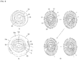
- FIG. 4 shows an embodiment in which a compressor according to the present disclosure has a plurality of oil feeding channels.
- a compressor according to the present disclosure has a plurality of oil feeding channels.
- the compressor 10 may have the first oil channel A and the second oil channel B as independent oil channels.
- oil may be introduced and discharged into and from the first oil channel A and the second oil channel B, individually, so that sufficient oil may be continuously supplied to the compression chamber 300.
- the first oil channel A may include a first oil transfer channel 319A defined in the main frame 310 to move the oil supplied from the rotatable shaft, and a first fixed oil channel 329A defined in the fixed end plate 321 to communicate with the first oil transfer channel 319A and extending up to a distal end of the outlet A1 of the first oil channel.
- the first oil transfer channel 319A may include a first main oil channel 3191A passing through the main shaft receiving portion 318 to receive oil, a first oil passage channel 3192A which extends from the first main oil channel 3191A toward the outer circumferential face along the main end plate 311 and through which the oil passes, and a first oil discharge channel 3193A connected to the distal end of the first oil passage channel 3192A and extending toward the fixed frame 320 to discharge the oil.
- the first fixed oil channel 329A may include a first oil inflow channel 3291A defined inside the fixed side plate to communicate with the first oil discharge channel 3193A to receive the oil supplied to the first oil transfer channel, a first oil flow channel 3292A constructed to communicate with the first oil inflow channel 3291A and defined inside the fixed end plate to move the oil supplied from the first oil inflow channel 3291A to the fixed wrap 332, and a first lubrication oil channel 3292A extending from the first oil flow channel to the outlet A1 of the first oil channel.
- the second oil channel may include a second oil transfer channel 329B which is defined in the main frame 310 and is spaced apart from the first oil transfer channel 319A, and, along which the oil supplied from the rotatable shaft moves, and a second fixed oil channel 329B defined in the fixed end plate and constructed to communicate with the second oil transfer channel 329B and extending up to the distal end of the outlet B1 of the second oil channel.
- a second oil transfer channel 329B which is defined in the main frame 310 and is spaced apart from the first oil transfer channel 319A, and, along which the oil supplied from the rotatable shaft moves
- a second fixed oil channel 329B defined in the fixed end plate and constructed to communicate with the second oil transfer channel 329B and extending up to the distal end of the outlet B1 of the second oil channel.
- the second oil transfer channel 319B may include a second main oil channel 3191B passing through the main shaft receiving portion 318 and receiving oil, a second oil passage channel 3192B which extends from the second main oil channel 3191B toward the outer circumferential face along the main end plate 311 and through which the oil passes, and a second oil discharge channel 3193B connected to the distal end of the second oil passage channel 3192B and extending toward the fixed frame 320 to discharge the oil.
- the second fixed oil channel 329B may include a second oil inflow channel 3291B which is defined inside the fixed side plate to communicate with the second oil discharge channel 3193B, and into which oil supplied to the second oil transfer channel flows, a second oil flow channel 3292B which is constructed to communicate with the second oil inflow channel 3291B and defined inside the fixed end plate and moves the oil supplied to the second oil inflow channel 3291B to the fixed wrap 332, and a second lubrication oil channel 3292B extending from the second oil flow channel to the outlet B1 of the second oil channel.
- the first oil channel A and the second oil channel B may have similar shapes. However, the outlet A1 of the first oil channel may be closer to the discharge hole 326 than the outlet B1 of the second oil channel may, and may be closer to the inner face of the orbiting wrap 333 than the outlet B 1 of the second oil channel may.
- the outlet A1 of the first oil channel rather than the outlet B1 of the second oil channel smoothly supplies oil to the lower pressure region.
- Both of the outlet A1 of the first oil channel and the outlet B1 of the second oil channel may be prevented from being closed by the orbiting wrap 333 at the same time.
- first oil channel A may be disposed in an outer channel formed by the outer face of the fixed wrap 323 and the inner face of the orbiting wrap 333
- second oil channel B may be disposed in an inner channel formed by the inner face of the fixed wrap 323 and the outer face of the orbiting wrap 323.
- outlet A1 of the first oil channel and the outlet B1 of the second oil channel may be spaced from each other by a distance larger than the thickness of the orbiting wrap 333.
- at least one of the outlet A1 of the first oil channel and the outlet B1 of the second oil channel may be kept open regardless of the position of the orbiting wrap 333, thereby preventing the situation that the oil feeding to the compressing assembly 300 is stopped.
- FIG. 5 shows a structure to which the oil feeding channel of FIG. 4 is applied.
- the compressor 10 includes a first oil channel A defined in at least one of the orbiting scroll 320 or the main frame 310, and in the fixed scroll 320 to feed the oil supplied from the rotatable shaft to a region between the orbiting scroll and the fixed scroll, and a second oil channel B defined in at least one of the orbiting scroll 330 or the main frame 310, and defined in the fixed scroll 320 and spaced from the first oil channel A to feed the oil supplied from the rotatable shaft 230 to a region between the orbiting scroll 330 and the fixed scroll 310.
- the compressor 10 When the first oil channel A is constructed to communicate with the intermediate pressure region VI, and the second oil channel B is constructed to communicate with the lower pressure region V2, the oil supplied through the oil feeding hole 234 may be supplied to the intermediate pressure region V1 through the first oil channel A, and may be supplied to the lower pressure region V2 through the second oil channel B.
- the compressor 10 according to the present disclosure has the first oil channel A that supplies oil to the intermediate pressure region V1 for a high pressure ratio operation, and the second oil channel B which supplies oil to the lower pressure region V2 for a lower pressure ratio operation.
- the first oil channel A and the second oil channel B are both installed in the intermediate pressure region V1 or the lower pressure region V2 at the same time, the first oil channel A may be placed in the outer channel formed by the inner face of the orbiting wrap 333 and the outer face of the fixed wrap 323, while the second oil channel B may be disposed in an inner channel formed by an outer face of the orbiting wrap 333 and an inner face of the fixed wrap 323.
- the first oil channel A and the second oil channel B may supply oil to different oil channels, respectively, and both thereof may be prevented from being closed by the orbiting wrap 333 or the fixed wrap 323.
- the compressor 10 may have a region to which the oil feedings through the first oil channel A and the second oil channel B are simultaneously performed. Furthermore, in an angle range of 190° to 270° in which oil feeding through the first oil channel A is blocked, the oil feeding may be continued through the second oil channel B. Further, in an angle range of 0 to 80 degrees, and 270 degrees to 360 degrees in which oil feeding through the second oil channel B is blocked, the oil feeding may continue through the first oil channel A.
- the oil feeding to the compressing assembly 300 may be fundamentally activated at all times.
- FIG. 6 shows another oil feeding channel structure of the compressor according to the present disclosure.
- the oil feeding channel I according to the present disclosure may be defined in the orbiting scroll 330. That is, the process of installing the oil feeding channel in the fixed scroll 320 may be omitted.
- the outlet A1 of the first oil channel and the outlet B1 of the second oil channel may be defined in the orbiting end plate 331.
- the oil feeding channel I may include an orbiting oil channel 339 passing through the orbiting scroll 330.
- the orbiting oil channel 339 may include an orbiting oil input channel 3391 through which the oil delivered from the first oil feeding hole 234a or the first oil feeding groove 2341a is injected into the orbiting scroll, a connection oil channel 3392 extending from the orbiting oil input channel toward the outer circumferential face of the orbiting scroll, a branched oil channel 3393 branching from the connection oil channel 3392 toward the fixed scroll 320 and defining the outlet B1 of the second oil channel, and a communication oil channel 3394 that is spaced from the connection oil channel 3392 toward the outer circumferential face of the orbiting end plate 331 by a distance larger than a distance by which the second oil channel is spaced from the connection oil channel 3392, thereby to form the outlet A1 of the first oil channel.
- the outlets A1, B1 of the first and second oil channels A, B are openings on a surface of the orbiting end plate 331 on which the orbiting wrap is
- the first oil channel A and the second oil channel B may share the orbiting oil input channel 3391 and the connection oil channel 3392.
- the oil delivered through the rotatable shaft 230 may be directly supplied to the orbiting wrap 333 and the fixed wrap 323 through the orbiting scroll 330.
- the scroll type compressor 300 may include the pressure reducing means 360 which is inserted into the oil transfer channel 330 to adjust the supply amount of oil.
- the pressure reducing means 360 reduced the cross-sectional area of the oil transfer channel 330 to generate the oil channel resistance to prevent excessive oil from being supplied.
- the orbiting wrap 333 may be disposed between the outlet A1 of the first oil channel and the outlet B1 of the second oil channel. Between adjacent orbiting wraps 333, the outlet A1 of the first oil channel and the outlet B1 of the second oil channel may be disposed.
- the outlet A1 of the first oil channel may be closer to the outer face of the orbiting wrap 333, while the outlet B 1 of the second oil channel may be closer to the inner face of the orbiting wrap. That is, the outlet A1 of the first oil channel and the outlet B 1 of the second oil channel may be closer to a first orbiting wrap 333 disposed between the outlet A1 of the first oil channel and the outlet B1 of the second oil channel than to a second orbiting wrap 333 adjacent to the first orbiting wrap 333.
- outlet A1 of the first oil channel and the outlet B1 of the second oil channel may supply oil to the inner and outer faces of the orbiting wrap 333, respectively.
- first oil channel A may be disposed in an outer channel formed by the outer face of the fixed wrap 323 and the inner face of the orbiting wrap 333
- second oil channel B may be disposed in an inner channel formed by the inner face of the fixed wrap 323 and the outer face of the orbiting wrap 323.
- outlet A1 of the first oil channel and the outlet B1 of the second oil channel may be spaced apart from each other by a distance larger than the thickness of the fixed wrap 323.
- the outlet B1 of the second oil channel may be spaced apart from the fixed wrap 323 and may be opened.
- the outlet A1 of the first oil channel may be spaced apart from the fixed wrap 323 and may be opened.
- At least one of the outlet A1 of the first oil channel and the outlet B1 of the second oil channel may be kept open regardless of the position of the fixed wrap 323, and oil feeding to the compressing assembly 300 is prevented from being stopped.
- both of the branched oil channel 3393 and the communication oil channel 3394 may be disposed between a specific orbiting wrap 333 and an orbiting wrap 333 adjacent thereto. That is, both of the outlet A1 of the first oil channel and the outlet B1 of the second oil channel may be disposed between the outer orbiting wrap 333 and the inner orbiting wrap 333.
- An orbiting wrap 333 may not be formed between the outlet A1 of the first oil channel and the outlet B1 of the second oil channel, and a fixed wrap 323 may be selectively disposed therebetween.
- the outlets A1, B1 of the first and second oil channels A, B are openings on a surface of the orbiting end plate 331 on which the orbiting wrap is disposed.
- the outlet A1 of the first oil channel may be disposed adjacent to the inner face of the orbiting wrap 333, and the outlet B1 of the second oil channel may be defined adjacent to the outer face of the orbiting wrap 333. Therefore, the first oil channel A may supply oil to the outer channel, and the second oil channel B may supply oil to the inner channel.
- the orbiting scroll 330 is orbiting, one of the inner channel and the outer channel invades the fixed wrap 323, but the other thereof may be spaced from the fixed wrap 323.
- the first oil channel A and the second oil channel B may be arranged independently of each other.
- the first oil channel A may include a first orbiting oil input channel 3391 which passes through the orbiting end plate and through which oil is input to the orbiting scroll, a first connection oil channel 3392 extending from the first orbiting oil input channel toward the outer circumferential face of the orbiting scroll, and a branched oil channel 3393 passing through the orbiting end plate and communicating the connection oil channel and the outlet A1 of the first oil channel.
- the outlet A1 of the first oil channel A is an opening on a surface of the orbiting end plate 331 on which the orbiting wrap is disposed.
- the second oil channel may include a second orbiting oil input channel 3391B which is spaced apart from the first orbiting oil input channel and passes through the orbiting end plate, and through which oil is introduced into the orbiting scroll, a second connection oil channel 3392B extending from the second orbiting oil input channel toward the outer circumferential face of the orbiting scroll, and a communication oil channel 3394 passing through the orbiting end plate and communicating the second connection oil channel 3392B with the outlet B1 of the second oil channel.
- a second orbiting oil input channel 3391B which is spaced apart from the first orbiting oil input channel and passes through the orbiting end plate, and through which oil is introduced into the orbiting scroll
- a second connection oil channel 3392B extending from the second orbiting oil input channel toward the outer circumferential face of the orbiting scroll
- a communication oil channel 3394 passing through the orbiting end plate and communicating the second connection oil channel 3392B with the outlet B1 of the second oil channel.
- first oil channel A and the second oil channel B may be independently defined.
- the first oil channel A may independently supply oil to the inner channel
- the second oil channel B may independently feed the oil to the outer channel.
- the oil may be smoothly supplied to the outer channel through the second oil channel B.
- At least one of the first oil channel A and the second oil channel B may be maintained in an open state. Further, sufficient oil may be supplied through the first oil channel A and the second oil channel B while oil is not accumulated therein.
- FIG. 7 shows another embodiment of the oil feeding structure of the compressor according to the present disclosure.
- the oil feeding channel I may include a first oil channel A passing through one of the orbiting scroll 330 and the fixed scroll 320 and a second oil channel passing through the other one of the orbiting scroll 330 and the fixed scroll 320 B.
- FIG. 7 shows that the first oil channel A passes through the main frame 310 and the fixed scroll 320, and the second oil channel B passes through the orbiting scroll 330.
- the second oil channel B passes through the main frame 310 and the fixed scroll 320, and the first oil channel A passes through the orbiting scroll 330.
- the first oil channel A may include an oil transfer channel 319 which is defined in the main frame, and through along the oil supplied from the rotatable shaft flows, a fixed oil channel 329 defined in the fixed scroll and constructed to communicate with the oil transfer channel and including an outlet of the first oil channel that supplies the oil into a region between the orbiting wrap and the fixed wrap.
- the second oil channel B may include an orbiting oil input channel 3191 which passes through the orbiting end plate and through which oil is injected into the orbiting scroll, a connection oil channel 3192 that extends from the orbiting oil input channel toward the outer circumferential face of the orbiting scroll, and a communication oil channel 3394 passing through the orbiting end plate and communicating the connection oil channel with the outlet of the second oil channel.
- At least one of the outlet A1 of the first oil channel and the outlet B1 of the second oil channel may be kept open.
- the second oil channel B is defined in the orbiting scroll 330 and does not pass through the fixed scroll 320, the oil channel resistance therein is smaller than that in the first oil channel A. Therefore, oil may be effectively supplied to the lower pressure region V2.
- At least one of the outlet A1 of the first oil channel and the outlet B1 of the second oil channel may be kept open regardless of the position of the fixed wrap 323 or orbiting wrap 333, and the oil feeding to the compressing assembly 300 may be prevented from being stopped.
- FIG. 8 shows how the compressor operates according to the present disclosure.
- FIG. 8 shows the orbiting scroll
- (b) in FIG. 8 shows the fixed scroll
- (c) in FIG. 8 shows the process of compressing the refrigerant using the orbiting scroll and the fixed scroll.
- the orbiting scroll 330 may include the orbiting wrap 333 on one face of the orbiting end plate 331, and the fixed scroll 320 may include the fixed wrap 323 on one face of the fixed end plate 321.
- the orbiting scroll 330 may be embodied as a sealed rigid body to prevent the refrigerant from being discharged out thereof.
- the fixed wrap 323 and the orbiting wrap 333 may be formed in an involute shape and may be engaged with each other at two or more points to form a compression chamber in which the refrigerant is compressed.
- the involute refers to a particular type of curve that is dependent on another shape or curve.
- An involute of a curve is the locus of a point on a piece of taut string as the string is either unwrapped from or wrapped around the curve.
- the fixed wrap 323 and the orbiting wrap 333 are formed by combining 20 or more arcs with each other.
- the radiuses of curvature of the arcs vary.
- the compressor according to the present disclosure is constructed so that the rotatable shaft 230 passes through the fixed scroll 320 and the orbiting scroll 330, so that the radius of curvature of the fixed wrap 323 and the orbiting wrap 333 and the compression space defined therebetween are reduced.
- the space in which the refrigerant is discharged to improve the compression ratio.
- the radius of curvature of a portion just before a portion of the fixed wrap 323 and the orbiting wrap 333 at which the refrigerant is discharged may be smaller than that of the shaft receiving portion receiving the rotatable shaft.
- the fixed wrap 323 and the orbiting wrap 333 may be curved at the smallest radius of curvature in the vicinity of the discharge hole 326, and the radius of curvature thereof may increase toward the inlet 325.
- the fixed wrap 323 and the orbiting wrap 333 have the varying radius of curvature between the discharge hole 326 and inlet 325.
- refrigerant I flows into the inlet 325 of the fixed scroll 320, and refrigerant II flowing before the refrigerant I is located near the discharge hole 326 of the fixed scroll 320.
- the refrigerant I exists in a region in which the outer surfaces of the fixed wrap 323 and the orbiting wrap 333 are engaged with each other, and the refrigerant II is present and sealed in another region where the fixed wrap 323 and the orbiting wrap 333 are engaged with each other at two points thereof.
- the region where the fixed wrap 323 and the orbiting wrap 333 are engaged with each other at the two points moves along the extension direction of the fixed wrap 323 and the orbiting wrap 333 according to the position change of the orbiting wrap 333, such that the volume of the refrigerant begins to be reduced.
- the refrigerant I is compressed.
- the refrigerant II is further reduced in volume and compressed and begins to be guided to the discharge hole 326.
- the refrigerant II is discharged from the discharge hole 326, and the refrigerant I moves as the region where the fixed wrap 323 and the orbiting wrap 333 are engaged with each other at the two-points moves clockwise, and the volume thereof decreases and the refrigerant begins to be further compressed.
- the refrigerant may be compressed linearly or continuously while moving inside the fixed scroll.
- the refrigerant discontinuously flows into the inlet 325, but this is for illustration only.
- the refrigerant may be supplied continuously, and the refrigerant may be accommodated and compressed in the region defined by the two points at which the fixed wrap 323 and the orbiting wrap 333 are engaged with each other.
Landscapes
- Engineering & Computer Science (AREA)
- Mechanical Engineering (AREA)
- General Engineering & Computer Science (AREA)
- Rotary Pumps (AREA)
- Applications Or Details Of Rotary Compressors (AREA)
- Transition And Organic Metals Composition Catalysts For Addition Polymerization (AREA)
Abstract
Description
- The present disclosure relates to a compressor. More specifically, the present disclosure relates to a scroll type compressor having an oil feeding channel capable of supplying oil to a compressing assembly in which refrigerant is compressed.
- Generally, a compressor is an apparatus applied to a refrigeration cycle such as a refrigerator or an air conditioner, which compresses refrigerant to provide work necessary to generate heat exchange in the refrigeration cycle.
- The compressors may be classified into a reciprocating type compressor, a rotary type compressor, and a scroll type compressor based on a scheme in which the refrigerant is compressed. In the scroll type compressor, while an orbiting scroll is engaged with a fixed scroll fixed in an internal space of a sealed container, the orbiting scroll orbits, thereby to define a compression chamber between a fixed wrap of the fixed scroll and an orbiting wrap of the orbiting scroll.
- Compared with other types of the compressors, the scroll type compressor may obtain a relatively high compression ratio because the refrigerant is continuously compressed using the scrolls engaged with each other, and may obtain a stable torque because suction, compression, and discharge of the refrigerant proceed smoothly. For this reason, the scroll type compressor is widely used for compressing the refrigerant in the air conditioner and the like.
- Referring to Japanese Patent No.
6344452 - The compression assembly includes a fixed scroll fixed to the casing and having a fixed wrap, and an orbiting scroll including an orbiting wrap orbiting in a state of being engaged with the fixed wrap via the rotatable shaft. In the conventional scroll type compressor, the rotatable shaft is eccentric, and the orbiting scroll is fixed to the eccentric rotatable shaft and orbits. Thus, the orbiting scroll orbits along the fixed scroll to compress the refrigerant.
- In the conventional scroll type compressor, the compression assembly is generally disposed below the discharger, and the driver is generally disposed below the compression assembly. Further, the rotatable shaft generally has one end coupled to the compression assembly and the other end passing through the driver.
- The conventional scroll type compressor has difficulty in supplying oil into the compression assembly because the compression assembly is disposed above the driver and is closer to the discharger. Further, an additional lower frame under the driver is required to separately support the rotatable shaft connected to the compression assembly. Further, in the conventional scroll compressor, because action points of a gas force generated via the compression of the refrigerant and a reaction force supporting the gas force do not coincide with each other within the compression assembly, the orbiting scroll tilts, resulting in a problem of lowering efficiency and reliability thereof.
- In order to solve such problems, referring to Korean Patent Application Publication No.
10-2018-0124636 - The shaft-through scroll type compressor has the advantage of smooth oil supply since the compressing
assembly 300 is closer to an oil storage space than the driver is. Further, since thecompressing assembly 300 itself supports the rotatable shaft extending from the driver, a structure for separately supporting the rotatable shaft may be omitted, thereby simplifying a structure thereof. - Further, when the rotatable shaft extends through an entirety of the
compressing assembly 300, the rotatable shaft supports vibration or pressure generated in the compressingassembly 300 in a longitudinal direction, thereby improving the reliability of the compressor. -
FIG. 1 shows a detailed structure of the compressing assembly of the conventional compressor. - Referring to (a) in
FIG. 1 , the compressing assembly may include anorbiting scroll 330 that rotatably accommodates arotatable shaft 230, and afixed scroll 320 engaging with the orbiting scroll to form a compression chamber in which the refrigerant is compressed, and amain frame 310 mounted on thefixed scroll 320 to accommodate theorbiting scroll 330 therein. - The
rotatable shaft 230 may include aneccentric shaft 232 having an diameter expanding in a biased manner as accommodated in the orbitingscroll 330. Accordingly, as therotatable shaft 230 rotates, theeccentric shaft 232 presses theorbiting scroll 330 along a circumference of thefixed scroll 320 to continuously compress the refrigerant flowing along the orbitingscroll 330 and thefixed scroll 320. - Since the orbiting scroll 330 and the
fixed scroll 320 may cause friction therebetween in the process of compressing the refrigerant, and may be overheated as the temperature of the refrigerant increases, the conventional compressor may further include an oil feeding channel passing through therotatable shaft 230 and themain frame 310 and thefixed scroll 320. The oil feeding channel I extends to an area facing theorbiting wrap 333 of the orbitingscroll 330 to deliver the oil to the compression chamber. - In order to smoothly supply the oil to the orbiting
wrap 333, an outlet of the oil feeding channel I may be disposed at one of an inner channel A (i.e. an inner compression chamber A) spaced from an inner face of theorbiting wrap 333 or an outer channel B (i.e. an outer compression chamber B) spaced from an outer face of the orbitingwrap 333. The inner face of the orbitingwrap 333 means a radially inner surface of the orbitingwrap 333, and the outer face of the orbitingwrap 333 means a radially outer surface of the orbitingwrap 333. The inner face and the outer face of the orbitingwrap 333 are opposite to each other with respect to a center line of the orbitingwrap 333 forming a scroll shape. - However, the outlet of the oil feeding channel I may be blocked by the orbiting
wrap 333 as the orbitingwrap 333 moves according to the rotation of theeccentric shaft 232. For example, when the outlet of the oil feeding channel I is disposed at the outer channel B, and when theorbiting wrap 333 moves to the outlet of the oil feeding channel I, the oil feeding channel I may be closed such that the oil feeding is stopped. - (b) in
FIG. 1 shows an oil feeding pressure according to an angle at which the orbitingwrap 333 extends in a direction in which the orbitingwrap 333 accommodates therotatable shaft 230 relative to a refrigerant intake hole of the fixed scroll through which the refrigerant is sucked. - Referring to a graph (b) in
FIG. 1 , it may be seen that oil is supplied to the outer channel B in a section of 0 to 30 degrees and a section of 270 degrees to 360 degrees, while the oil is supplied to the inner channel A in a section of 70 to 220 degrees. However, it may be seen that the oil feeding channel I is closed by the orbitingwrap 333 so that the oil feeding is stopped in a section between 30 degrees and 70 degrees and a section between 220 degrees and 270 degrees. - Thus, the conventional compressor has a problem in that the oil feeding stops in the specific section, so that the oil cannot be fed to the entire compressor. Further, there is a problem in that the reliability of the compressor cannot be guaranteed due to structural limitations such as severe wear and damage in the specific section.
- A purpose of the present disclosure is to provide a scroll type compressor in which both of outlets for feeding oil into a region between the orbiting scroll and the fixed scroll may be prevented from being blocked at the same time even when the orbiting scroll moves by the rotatable shaft.
- A purpose of the present disclosure is to provide a scroll type compressor in which a plurality of oil channels to supply oil are defined to prevents oil feeding from being interrupted.
- A purpose of the present disclosure is to provide a scroll type compressor in which all of a plurality of oil channels for supplying oil may be prevented from being blocked no matter where the orbiting scroll is positioned.
- A purpose of the present disclosure is to provide a scroll type compressor having oil feeding channels for feeding the oil to the inner and outer faces of the orbiting wrap of the orbiting scroll.
- A purpose of the present disclosure is to provide a scroll type compressor in which a plurality of oil feeding channels may be defined in on a main scroll and a fixed scroll, or a plurality of oil feeding channels may be defined in the orbiting scroll.
- The present disclosure provides a compressor having a first oil channel supplying oil to a compression chamber formed by an orbiting scroll and a fixed scroll, and a second oil channel spaced from the first oil channel to feed the oil.
- Each of the first oil channel and the second oil channel may act as each direct oil injection channel. That is, each of the oil feeding lines before a
crank angle 0° may be formed such that each of oil feeding lines to each of compression chambers may be created. - The first oil channel and the second oil channel may be arranged such that oil feeding through at least one of the first oil channel or the second oil channel is always available. Therefore, a structure capable of always feeding the oil into all regions of the compression chamber may be formed.
- In the compressor according to the present disclosure, the first oil channel may act as an oil feeding channel having a conventional differential pressure oil feeding structure, and the second oil channel may act as a lower pressure ratio oil feeding channel. Therefore, the oil feeding under the normal operation range and the oil feeding under the lower pressure ratio may also be performed at the same time. The lower pressure power ratio oil feeding line may be constructed to communicate with the refrigerant inlet for smooth oil feeding even at a pressure ratio of 1.1 or lower. Further, the oil feeding line for direct injection of oil to the inlet after decompression via a decompression pin for the oil of the oil storage as the discharge pressure space may be formed. As a result, the low pressure ratio region oil feeding amount may be improved and bearing reliability may be secured. In this connection, the compressor according to the present disclosure may be constructed to improve the oil feeding amount by securing the differential pressure amount via adjustment of the oil feeding communication angle (for example, before start
angle 0°C). Further, the compressor according to the present disclosure may be constructed to secure bearing reliability during low pressure ratio operation by securing an oil feeding amount to prevent abnormal behavior of the orbiting scroll by improving the intermediate pressure of the orbiting scroll. Therefore, it is possible to improve the oil feeding efficiency under the lower pressure force ratio. - Further, the compressor according to the present disclosure may secure the reliability of the compressor via the dual oil feeding channels that may allow always-oil feeding. One of the first oil channel and the second oil channel may be defined as a communication hole that may be always opened. Thus, a structure in which oil feeding is always possible may be implemented.
- In one example, the first oil channel and the second oil channel may supply oil to different regions. The first oil channel and the second oil channel may be constructed to be spaced apart from each other by a spacing larger than a thickness of the orbiting wrap, and may be located in positions at which both of the first oil channel and the second oil channel are prevented from being simultaneously closed by the orbiting wrap or the fixed wrap.
- The outlet of the first oil channel may be closer to the refrigerant discharge hole or the rotatable shaft than the outlet of the second oil channel may be. In one example, the second oil channel may supply oil to a relatively lower pressure region, and the first oil channel may supply oil to a relatively high pressure region.
- Accordingly, when oil is not supplied to the high pressure region, oil may be supplied to the lower pressure region. Alternatively, when oil is not supplied to the lower pressure region, oil may be supplied to the high pressure region.
- Further, even when the orbiting wrap moves and closes the first oil channel, the second oil channel may be opened. Alternatively, even when the orbiting wrap moves and closes the second oil channel, the first oil channel may be opened. As a result, a state in which the oil is fed to the inside of the compressor may always be maintained.
- The scroll type compressor may have a first oil channel located inside the orbiting scroll and a second channel located outside the orbiting scroll.
- In one embodiment, a compressor includes a casing including a discharger to discharge refrigerant, and an oil storage space for storing oil therein; a driver coupled to an inner circumferential face of the casing; a rotatable shaft coupled to the driver and constructed to supply the oil; and a compressing assembly coupled to the rotatable shaft to compress the refrigerant, wherein the compressing assembly is lubricated with the oil.
- The compressing assembly includes: an orbiting scroll including: an orbiting end plate supporting the rotatable shaft rotatably and performing an orbiting motion; and an orbiting wrap extending along a circumference of the orbiting end plate to compress the refrigerant; a fixed scroll including: a fixed end plate having a refrigerant inlet and a discharge hole defined therein, wherein the discharge hole is spaced from the inlet and discharges the compressed refrigerant; and a fixed wrap extending along the orbiting wrap and on the fixed end plate to compress the refrigerant; a main frame mounted on the fixed end plate to accommodate therein the orbiting scroll, wherein the rotatable shaft passes through the main frame; and an oil feeding channel passing through the orbiting end plate or the fixed end plate and feeding the oil delivered from the rotatable shaft into a region between the orbiting wrap and the fixed wrap. In the present description, the meaning of "passing through" comprises i) passing completely from one end surface of an element to the other end surface thereof, and ii) passing partially from the one end surface of the element up to a certain middle point, not up to the other end surface thereof..
- The oil feeding channel includes: a first oil channel constructed to supply the oil in a first region between the fixed wrap and the orbiting wrap; and a second oil channel separated from the first oil channel or branched from the first oil channel to supply the oil to a second region other than the first region, wherein a radial distance between an outlet of the first oil channel and a central axis of the rotatable shaft is smaller than a radial distance between an outlet of the second oil channel and the central axis of the rotatable shaft.
- In another embodiment, in the compressor according to the present disclosure, the first oil channel and the second oil channel may pass through the orbiting end plate, and the outlet of the first oil channel and the outlet of the second oil channel may be defined in the orbiting end plate.
- The present disclosure has the effect that the oil feeding may be prevented from being stopped regardless of the position of the orbiting scroll.
- The present disclosure has the effect that oil feeding may always be performed no matter where the orbiting scroll is located.
- The present disclosure is effective in preventing compressor wear and overheating by maintaining the oil supply to all of the oil channels formed by the orbiting wrap and the fixed wrap.
-
-
FIG. 1 shows the structure of the conventional compressor compressing assembly. -
FIG. 2 shows a basic structure of a compressor according to the present disclosure. -
FIG. 3 shows an embodiment of an oil feeding structure applied to a compressing assembly of the compressor according to the present disclosure. -
FIG. 4 shows an embodiment in which the oil feeding structure ofFIG. 3 may be implemented. -
FIG. 5 shows an embodiment in which the oil feeding structure ofFIG. 4 is implemented in the compressing assembly. -
FIG. 6 shows another embodiment of an oil feeding structure applied to the compressing assembly of the compressor according to the present disclosure. -
FIG. 7 shows still another embodiment of an oil feeding structure applied to the compressing assembly of the compressor according to the present disclosure. -
FIG. 8 shows how the compressor according to the present disclosure works. - For simplicity and clarity of illustration, elements in the figures are not necessarily drawn to scale. The same reference numbers in different figures denote the same or similar elements, and as such perform similar functionality. Furthermore, in the following detailed description of the present disclosure, numerous specific details are set forth in order to provide a thorough understanding of the present disclosure. However, it will be understood that the present disclosure may be practiced without these specific details. In other instances, well-known methods, procedures, components, and circuits have not been described in detail so as not to unnecessarily obscure aspects of the present disclosure. Examples of various embodiments are illustrated and described further below. It will be understood that the description herein is not intended to limit the claims to the specific embodiments described. On the contrary, it is intended to cover alternatives, modifications, and equivalents as may be included within the spirit and scope of the present disclosure as defined by the appended claims. The terminology used herein is for the purpose of describing particular embodiments only and is not intended to be limiting of the present disclosure. As used herein, the singular forms "a" and "an" are intended to include the plural forms as well, unless the context clearly indicates otherwise. It will be further understood that the terms "comprises", "comprising", "includes", and "including" when used in this specification, specify the presence of the stated features, integers, operations, elements, and/or components, but do not preclude the presence or addition of one or more other features, integers, operations, elements, components, and/or portions thereof.
-
FIG. 2 describes the basic structure of the compressor of one embodiment of the present disclosure. Ascroll type compressor 10 according to the present disclosure is generally installed on a circuit of a refrigerant cycle having acondenser 2, an expansion valve 3, and an evaporator 4. - Referring to
FIG. 2 , thescroll type compressor 10 according to an embodiment of the present disclosure may include acasing 100 having therein a space in which fluid is stored or flows, adriver 200 coupled to an inner circumferential face of thecasing 100 to rotate arotatable shaft 230, and acompression assembly 300 coupled to therotatable shaft 230 inside the casing and compressing the fluid. - Specifically, the
casing 100 may include adischarger 121 through which refrigerant is discharged at one side. Thecasing 100 may include a receivingshell 110 formed in a cylindrical shape to receive thedriver 200 and thecompression assembly 300 therein, adischarge shell 120 coupled to one end of the receivingshell 110 and having thedischarger 121, and a sealingshell 130 coupled to the other end of the receivingshell 110 to seal the receivingshell 110. - The
driver 200 includes astator 210 for generating a rotating magnetic field, and arotor 220 constructed to rotate by the rotating magnetic field. Therotatable shaft 230 may be coupled to therotor 220 to be rotated together with therotor 220. - The
stator 210 has a plurality of slots defined in an inner circumferential face thereof along a circumferential direction and a coil is wound around the plurality of slots. Further, thestator 210 may be fixed to an inner circumferential face of the receivingshell 110. A permanent magnet may be coupled to therotor 220, and therotor 220 may be rotatably coupled within thestator 210 to generate rotational power. Therotatable shaft 230 may be pressed into and coupled to a center of therotor 220. - The
compression assembly 300 may include afixed scroll 320 coupled to the receivingshell 110 and disposed in a direction away from thedischarger 121 with respect to thedriver 200, anorbiting scroll 330 coupled to therotatable shaft 230 and engaged with the fixedscroll 320 to define a compression chamber, and amain frame 310 accommodating theorbiting scroll 330 therein and seated on the fixedscroll 320 to form an outer shape of thecompression assembly 330. - As a result, the lower
scroll type compressor 10 has thedriver 200 disposed between thedischarger 120 and thecompression assembly 300. In other words, thedriver 200 may be disposed at one side of thedischarger 120, and thecompression assembly 300 may be disposed in a direction away from thedischarger 121 with respect to thedriver 200. For example, when thedischarger 121 is disposed above thecasing 100, thecompression assembly 300 may be disposed below thedriver 200, and thedriver 200 may be disposed between thedischarger 120 and thecompression assembly 300. - Thus, when oil is stored in an oil storage space p of the
casing 100, the oil may be supplied directly to thecompression assembly 300 without passing through thedriver 200. In addition, since therotatable shaft 230 is coupled to and supported by thecompression assembly 300, a lower frame for rotatably supporting the rotatable shaft may be omitted. - In one example, the lower
scroll type compressor 10 according to the present disclosure may be configured such that therotatable shaft 230 passes through not only theorbiting scroll 330 but also the fixedscroll 320 to be in face contact with both theorbiting scroll 330 and the fixedscroll 320. - As a result, an inflow force generated when the fluid such as the refrigerant is flowed into the
compression assembly 300, a gas force generated when the refrigerant is compressed in thecompression assembly 300, and a reaction force for supporting the same may be directly exerted on therotatable shaft 230. Accordingly, the inflow force, the gas force, and the reaction force may be exerted to a point of application of therotatable shaft 230. As a result, since a tilting moment does not act on theorbiting scroll 320 coupled to therotatable shaft 230, tilting or overturn of the orbiting scroll may be blocked. In other words, tilting in an axial direction of the tilting may be attenuated or prevented, and the overturn moment of theorbiting scroll 330 may also be attenuated or suppressed. As a result, noise and vibration generated in the lowerscroll type compressor 10 may be blocked. In addition, the fixedscroll 320 is in face contact with and supports therotatable shaft 230, so that durability of therotatable shaft 230 may be reinforced even when the inflow force and the gas force act on therotatable shaft 230. In addition, a backpressure generated while the refrigerant is discharged to outside is also partially absorbed or supported by therotatable shaft 230, so that a force (normal force) in which theorbiting scroll 330 and the fixedscroll 320 become excessively close to each other in the axial direction may be reduced. As a result, a friction force between the orbitingscroll 330 and the fixedscroll 230 may be greatly reduced. - As a result, the
compressor 10 attenuates the tilting in the axial direction and the overturn or tilting moment of theorbiting scroll 330 inside thecompression assembly 300 and reduces the frictional force of the orbiting scroll, thereby increasing an efficiency and a reliability of thecompression assembly 300. - In one example, the
main frame 310 of thecompression assembly 300 may include amain end plate 311 disposed at one side of thedriver 200 or at a lower portion of thedriver 300, amain side plate 312 extending in a direction farther away from thedriver 200 from an inner circumferential face of themain end plate 311 and seated on the fixedscroll 330, and a mainshaft receiving portion 318 extending from themain end plate 311 to rotatably support therotatable shaft 230. - A
main hole 317 for guiding the refrigerant discharged from the fixedscroll 320 to thedischarger 121 may be further defined in themain end plate 311 or themain side plate 312. - The
main end plate 311 may further include anoil pocket 314 that is engraved in an outer face of the mainshaft receiving portion 318. Theoil pocket 314 may be defined in an annular shape, and may be defined to be eccentric to the mainshaft receiving portion 318. When the oil stored in the sealingshell 130 is transferred through therotatable shaft 230 or the like, theoil pocket 314 may be defined such that the oil is supplied to a portion where the fixedscroll 320 and theorbiting scroll 330 are engaged with each other. - The fixed
scroll 320 may include afixed end plate 321 coupled to the receivingshell 110 in a direction away from thedriver 300 with respect to themain end plate 311 to form the other face of thecompression assembly 300, a fixedside plate 322 extending from the fixedend plate 321 to thedischarger 121 to be in contact with themain side plate 312, and afixed wrap 323 disposed on an inner circumferential face of the fixedside plate 322 to define the compression chamber in which the refrigerant is compressed. - In one example, the fixed
scroll 320 may include a fixed through-hole 328 defined to pass through therotatable shaft 230, and a fixedshaft receiving portion 3281 extending from the fixed through-hole 328 such that the rotatable shaft is rotatably supported. The fixed shaft receiving portion 3331 may be disposed at a center of thefixed end plate 321. - A thickness of the
fixed end plate 321 may be equal to a thickness of the fixed shaft receiving portion 3381. In this case, the fixedshaft receiving portion 3281 may be inserted into the fixed through-hole 328 instead of protruding from the fixedend plate 321. - The fixed
side plate 322 may include an inflow hole 325 defined therein for flowing the refrigerant into the fixedwrap 323, and thefixed end plate 321 may includedischarge hole 326 defined therein through which the refrigerant is discharged. Thedischarge hole 326 may be defined in a center direction of the fixedwrap 323, or may be spaced apart from the fixedshaft receiving portion 3281 to avoid interference with the fixedshaft receiving portion 3281, or thedischarge hole 326 may include a plurality of discharge holes. - The fixed scroll may have a
bypass hole 327 defined therein through which the refrigerant discharged from thedischarge port 326 is discharged. Thebypass hole 327 may pass through thefixed end plate 321. - Further, the fixed
scroll 320 may further include a steppedface 324 extending in a stepwise manner from the fixedend plate 321 or the fixedside plate 322 in order to couple a muffler 500 to be described late thereto. A diameter of the steppedface 324 may be smaller than a diameter of thefixed end plate 321. - The
orbiting scroll 330 may include an orbitingend plate 331 disposed between themain frame 310 and the fixedscroll 320, and anorbiting wrap 333 disposed below the orbiting end plate to define the compression chamber together with the fixedwrap 323 in the orbiting end plate. - The
orbiting scroll 330 may further include an orbiting through-hole 338 defined through the orbitingend plate 331 to rotatably couple therotatable shaft 230. - The
rotatable shaft 230 may be constructed such that a portion thereof coupled to the orbiting through-hole 338 is eccentric. Thus, when therotatable shaft 230 rotates, theorbiting scroll 330 orbits in a state of being engaged with the fixedwrap 323 of the fixedscroll 320 to compress the refrigerant. - Specifically, the
rotatable shaft 230 may include amain shaft 231 coupled to thedriver 200 and rotating, and asupport shaft 232 connected to themain shaft 231 and rotatably coupled to thecompression assembly 300. Thesupport shaft 232 may be included as a member separate from themain shaft 231, and may accommodate themain shaft 231 therein, or may be integrated with themain shaft 231. - The
support shaft 232 may include amain support shaft 232c inserted into the mainshaft receiving portion 318 of themain frame 310 and rotatably supported, a fixedsupport shaft 232a inserted into the fixedshaft receiving portion 3281 of the fixedscroll 320 and rotatably supported, and aneccentric shaft 232b disposed between themain support shaft 232c and the fixedsupport shaft 232a, and inserted into the orbiting through-hole 338 of theorbiting scroll 330 and rotatably supported. - In this connection, the
main support shaft 232c and the fixedsupport shaft 232a may be coaxial to have the same axis center, and theeccentric shaft 232b may be formed such that a center of gravity thereof is radially eccentric with respect to themain support shaft 232c or the fixedsupport shaft 232a. In addition, theeccentric shaft 232b may have an outer diameter greater than an outer diameter of themain support shaft 232c or an outer diameter of the fixedsupport shaft 232a. As such, theeccentric shaft 232b may provide a force to compress the refrigerant while orbiting theorbiting scroll 330 when thesupport shaft 232 rotates, and theorbiting scroll 330 may be constructed to regularly orbit the fixedscroll 320 by theeccentric shaft 232b. - However, in order to prevent the orbiting scroll 320 from spinning, the
compressor 10 according to the present disclosure may further include an Oldham'sring 340 coupled to an upper portion of theorbiting scroll 320. The Oldham'sring 340 may be disposed between the orbitingscroll 330 and themain frame 310 to be in contact with both theorbiting scroll 330 and themain frame 310. The Oldham'sring 340 may be constructed to linearly move in four directions of front, rear, left, and right directions to prevent the rotation of theorbiting scroll 320. - In one example, the
rotatable shaft 230 may be constructed to completely pass through the fixedscroll 320 to protrude out of thecompression assembly 300. As a result, therotatable shaft 230 may be in direct contact with outside of thecompression assembly 300 and the oil stored in the sealingshell 130. Therotatable shaft 230 may supply the oil into thecompression assembly 300 while rotating. - The oil may be supplied to the
compression assembly 300 through therotatable shaft 230. Anoil supply channel 234 for supplying the oil to an outer circumferential face of themain support shaft 232c, an outer circumferential face of the fixedsupport shaft 232a, and an outer circumferential face of theeccentric shaft 232b may be formed at or inside therotatable shaft 230. - In addition, a plurality of
oil feed holes oil supply channel 234. Specifically, the oil feed hole may include a firstoil feed hole 234a, a second oil feed hole 234b, a thirdoil feed hole 234c, and a fourthoil feed hole 234d. First, the firstoil feed hole 234a may be defined to pass through the outer circumferential face of themain support shaft 232c. - The first
oil feed hole 234a may be defined to pass through into the outer circumferential face of themain support shaft 232c in theoil supply channel 234. In addition, the firstoil feed hole 234a may be defined to, for example, pass through an upper portion of the outer circumferential face of themain support shaft 232c, but is not limited thereto. That is, the firstoil feed hole 234a may be defined to pass through a lower portion of the outer circumferential face of themain support shaft 232c. For reference, unlike as shown in the drawing, the firstoil feed hole 234a may include a plurality of holes. In addition, when the firstoil feed hole 234a includes the plurality of holes, the plurality of holes may be defined only in the upper portion or only in the lower portion of the outer circumferential face of themain support shaft 232c, or may be defined in both the upper and lower portions of the outer circumferential face of themain support shaft 232c. - In addition, the
rotatable shaft 230 may include anoil shaft 233 passing through the muffler 500 to be described later to be in contact with the stored oil of thecasing 100. Theoil shaft 233 may include an extension shaft 233a passing through the muffler 500 and in contact with the oil, and a spiral groove 233b spirally defined in an outer circumferential face of the extension shaft 233a and in communication with thesupply channel 234. - Thus, when the
rotatable shaft 230 is rotated, due to the spiral groove 233b, a viscosity of the oil, and a pressure difference between a high pressure region S1 and an intermediate pressure region V1 inside thecompression assembly 300, the oil rises through theoil shaft 233 and thesupply channel 234 and is discharged into the plurality of oil feed holes. The oil discharged through the plurality ofoil feed holes orbiting scroll 240, but also absorbs frictional heat generated at friction portions between the components of thecompression assembly 300 and discharge the heat. - The oil guided along the
rotatable shaft 230 and supplied through the firstoil feed hole 234a may lubricate themain frame 310 and therotatable shaft 230. In addition, the oil may be discharged through the second oil feed hole 234b and supplied to a top face of theorbiting scroll 240, and the oil supplied to the top face of theorbiting scroll 240 may be guided to the intermediate pressure region through thepocket groove 314. For reference, the oil discharged not only through the second oil feed hole 234b but also through the firstoil feed hole 234a or the thirdoil feed hole 234d may be supplied to thepocket groove 314. - In one example, the oil guided along the
rotatable shaft 230 may be supplied to the Oldham'sring 340 and the fixedside plate 322 of the fixedscroll 320 installed between the orbitingscroll 240 and themain frame 230. Thus, wear of the fixedside plate 322 of the fixedscroll 320 and the Oldham'sring 340 may be reduced. In addition, the oil supplied to the thirdoil feed hole 234c is supplied to the compression chamber to not only reduce wear due to friction between the orbitingscroll 330 and the fixedscroll 320, but also form the oil film and discharge the heat, thereby improving a compression efficiency. - Although a centrifugal oil feed structure in which the lower
scroll type compressor 10 uses the rotation of therotatable shaft 230 to supply the oil to the bearing has been described, the centrifugal oil feed structure is merely an example. Further, a differential pressure supply structure for supplying oil using a pressure difference inside thecompression assembly 300 and a forced oil feed structure for supplying oil through a toroid pump, and the like may also be applied. - In one example, the compressed refrigerant is discharged to the
discharge hole 326 along a space defined by the fixedwrap 323 and theorbiting wrap 333. Thedischarge hole 326 may be more advantageously disposed toward thedischarger 121. This is because the refrigerant discharged from thedischarge hole 326 is most advantageously delivered to thedischarger 121 without a large change in a flow direction. - However, because of structural characteristics that the
compression assembly 300 is positioned in a direction away from thedischarger 121 with respect to thedriver 200, and that the fixedscroll 320 should be disposed at an outermost portion of thecompression assembly 300, thedischarge hole 326 is constructed to spray the refrigerant in a direction opposite to a direction toward thedischarger 121. - In other words, the
discharge hole 326 is defined to spray the refrigerant in a direction away from thedischarger 121 with respect to thefixed end plate 321. Therefore, when the refrigerant is sprayed into thedischarge hole 326 as it is, the refrigerant may not be smoothly discharged to thedischarger 121, and when the oil is stored in the sealingshell 130, the refrigerant may collide with the oil and be cooled or mixed. - In order to prevent this problem, the
compressor 10 in accordance with the present disclosure may further include the muffler 500 coupled to an outermost portion of the fixedscroll 320 and providing a space for guiding the refrigerant to thedischarger 121. - The muffler 500 may be constructed to seal one face disposed in a direction farther away from the
discharger 121 of the fixedscroll 320 to guide the refrigerant discharged from the fixedscroll 320 to thedischarger 121. - The muffler 500 may include a coupling body 520 coupled to the fixed
scroll 320 and a receiving body 510 extending from the coupling body 520 to define sealed space therein. Thus, the refrigerant sprayed from thedischarge hole 326 may be discharged to thedischarger 121 by switching the flow direction along the sealed space defined by the muffler 500. - Further, since the fixed
scroll 320 is coupled to the receivingshell 110, the refrigerant may be restricted from flowing to thedischarger 121 by being interrupted by the fixedscroll 320. Therefore, the fixedscroll 320 may further include thebypass hole 327 passing through thefixed end plate 321 to allow the refrigerant to pass through the fixedscroll 320. Thebypass hole 327 may be constructed to be in communication with themain hole 317. Thus, the refrigerant may pass through thecompression assembly 300, pass by thedriver 200, and be discharged to thedischarger 121. - Further, as the refrigerant flows more inwardly from an outer circumferential face of the fixed
wrap 323, the refrigerant is compressed to have a higher pressure. Thus, an interior of the fixedwrap 323 and an interior of theorbiting wrap 333 is maintained in a high pressure state. Accordingly, a discharge pressure is exerted to a rear face of the orbiting scroll as it is. Thus, in a reaction manner thereto, the backpressure is exerted from theorbiting scroll 330 toward the fixedscroll 320. Thecompressor 10 according to one embodiment of the present disclosure may further include abackpressure seal 350 that concentrates the backpressure on a portion where theorbiting scroll 320 and therotatable shaft 230 are coupled to each other, thereby preventing leakage between the orbitingwrap 333 and the fixedwrap 323. - The
backpressure seal 350 has a ring shape to maintain an inner circumferential face thereof at a high pressure, and separate an outer circumferential face thereof at an intermediate pressure lower than the high pressure. Therefore, the backpressure is concentrated on the inner circumferential face of thebackpressure seal 350, so that theorbiting scroll 330 is in close contact with the fixedscroll 320. - In this connection, when considering that the
discharge hole 326 is defined to be spaced apart from therotatable shaft 230, thebackpressure seal 350 may be configured such that a center thereof is biased toward thedischarge hole 326. In addition, due to thebackpressure seal 350, the oil supplied from the firstoil feed groove 234a may be supplied to the inner circumferential face of thebackpressure seal 350. Therefore, the oil may lubricate a contact face between the main scroll and the orbiting scroll. Further, the oil supplied to the inner circumferential face of thebackpressure seal 350 may generate a backpressure for pushing theorbiting scroll 330 to the fixedscroll 320 together with a portion of the refrigerant. - As such, the compression space of the fixed
wrap 323 and theorbiting wrap 333 may be divided into the high pressure region S1 inside thebackpressure seal 350 and the intermediate pressure region V1 outside thebackpressure seal 350 on the basis of thebackpressure seal 350. In one example, the high pressure region S1 and the intermediate pressure region V1 may be naturally divided because the pressure is increased in a process in which the refrigerant is inflowed and compressed. However, since the pressure change may occur critically due to a presence of thebackpressure seal 350, the compression space may be divided by thebackpressure seal 350. - In one example, the oil supplied to the
compression assembly 300, or the oil stored in thecasing 100 may flow toward an upper portion of thecasing 100 together with the refrigerant as the refrigerant is discharged to thedischarger 121. In this connection, because the oil is denser than the refrigerant, the oil may not be able to flow to thedischarger 121 by a centrifugal force generated by therotor 220, and may be attached to inner walls of thedischarge shell 110 and the receivingshell 120. The lowerscroll type compressor 10 may further include collection channels respectively on outer circumferential faces of thedriver 200 and thecompression assembly 300 to collect the oil attached to an inner wall of thecasing 100 to the oil storage space of thecasing 100 or the sealingshell 130. - The collection channel may include a
driver collection channel 201 defined in an outer circumferential face of thedriver 200, a compressor collection channel 301 defined in an outer circumferential face of thecompression assembly 300, and a muffler collection channel 501 defined in an outer circumferential face of the muffler 500. - The
driver collection channel 201 may be defined by recessing a portion of an outer circumferential face of thestator 210 is recessed, and the compressor collection channel 301 may be defined by recessing a portion of an outer circumferential face of the fixedscroll 320. In addition, the muffler collection channel 501 may be defined by recessing a portion of the outer circumferential face of the muffler. Thedriver collection channel 201, the compressor collection channel 301, and the muffler collection channel 501 may be defined in communication with each other to allow the oil to pass therethrough. - As described above, because the
rotation shaft 230 has a center of gravity biased to one side due to theeccentric shaft 232b, during the rotation, an unbalanced eccentric moment occurs, causing an overall balance to be distorted. Accordingly, the lowerscroll type compressor 10 according to the present disclosure may further include abalancer 400 that may offset the eccentric moment that may occur due to theeccentric shaft 232b. - Because the
compression assembly 300 is fixed to thecasing 100, thebalancer 400 is preferably coupled to therotation shaft 230 itself or therotor 220 constructed to rotate. Therefore, thebalancer 400 may include acentral balancer 410 disposed on a bottom of therotor 220 or on a face facing thecompression assembly 300 to cancel or reduce an eccentric load of theeccentric shaft 232b, and anouter balancer 420 coupled to a top of therotor 220 or the other face facing thedischarger 121 to offset an eccentric load or an eccentric moment of at least one of theeccentric shaft 232b and theouter balancer 420. - Because the
central balancer 410 is disposed relatively close to theeccentric shaft 232b, thecentral balancer 410 may directly offset the eccentric load of theeccentric shaft 232b. Accordingly, thecentral balancer 410 is preferably disposed eccentrically in a direction opposite to the direction in which theeccentric shaft 232b is eccentric. As a result, even when therotation shaft 230 rotates at a low speed or a high speed, because a spacing away from theeccentric shaft 232b is close, thecentral balancer 410 may effectively offset an eccentric force or the eccentric load generated in theeccentric shaft 232b almost uniformly. - The
outer balancer 420 may be disposed eccentrically in a direction opposite to the direction in which theeccentric shaft 232b is eccentric. However, theouter balancer 420 may be eccentrically disposed in a direction corresponding to theeccentric shaft 232b to partially offset the eccentric load generated by thecentral balancer 410. - As a result, the
central balancer 410 and theouter balancer 420 may offset the eccentric moment generated by theeccentric shaft 232b to assist therotation shaft 230 to rotate stably. -
FIG. 3 shows the compressing assembly and an oil feeding structure of the compressor according to the present disclosure. - (a) in
FIG. 3 shows a cross section of the compressing assembly, and (b) inFIG. 3 shows the fixedwrap 323 of the fixedscroll 320. - The compressing
assembly 300 according to the present disclosure may include an oil feeding channel I which passes through the orbitingend plate 331 and thefixed end plate 321 and delivers the oil delivered from theoil supply channel 234 of therotatable shaft 230 to the compression chamber defined between the orbitingwrap 333 and the fixedwrap 322. - The oil feeding channel I may include a plurality of oil feeding channels. All of the plurality of oil feeding channels may not be closed by the orbiting wrap 333 or the fixed
wrap 323 when theorbiting scroll 330 orbits around the fixedscroll 320. - For example, the oil feeding channel I may include a first oil channel A constructed to supply oil to a region between the
fixed wrap 323 and theorbiting wrap 333, and a second oil channel B separated from the first oil channel A or branched from the first oil channel A and constructed to supply oil to a region different from the region to which the first oil channel supplies the oil. - Accordingly, the
compressor 10 according to the present disclosure may supply oil to the compressingassembly 300 through the plurality of oil channels such as the first oil channel A and the second oil channel B. Therefore, it is possible to quickly and evenly supply the oil to the entire region of the compressingassembly 300. - A radial distance between an outlet A1 of the first oil channel and a central axis of the
rotatable shaft 230 may be smaller than a radial distance between an outlet B1 of the second oil channel and the central axis of therotatable shaft 230. - In the compressing
assembly 300 according to the present disclosure, a region which corresponds to the inside of thebackpressure seal 350, and in which thedischarge hole 326 is placed may be defined as a high pressure region S1. An intermediate pressure region V1 is outside the high pressure region S1 and has a pressure higher than the pressure of the incoming refrigerant. A region which is farther away from the rotatable shaft than the intermediate pressure region V1 is and is adjacent to the inlet of the refrigerant may be defined as a lower pressure region V2. For example, the lower pressure region V2 may refer to a region where the fixedwrap 323 starts to be wound by a half around the rotatable shaft 230 (about 0 to 180 degrees). - The outlet A1 of the first oil channel may be disposed in the intermediate pressure region VI, and the outlet B1 of the second oil channel may be disposed in the lower pressure region V2. Accordingly, the first oil channel A may preferentially supply oil to the high pressure region S1 faster than the second oil channel B may. The second oil channel B may preferentially supply oil to the lower pressure region V2 faster than the first oil channel A may. Therefore, whether the
compressor 300 compresses the refrigerant at high pressure or at a lower pressure, oil may be smoothly supplied through the first oil channel A and the second oil channel B. - In particular, the second oil channel B may be located outside the first oil channel A, or the outlet B1 of the second oil channel may be located closer to the refrigerant inlet than the outlet A1 of the first oil channel may. Thus, the second oil channel B may more effectively supply oil to the lower pressure region V2 than the first oil channel A may. That is, the second oil channel B may generate a greater differential pressure from that of the
oil supply channel 234 than the first oil channel A may, so that oil may be more effectively supplied to the lower pressure region V2. - In one example, when the
compressor 300 operates at lower pressure, the differential pressure between the lower pressure region V2 and the high pressure region S1 is not sufficiently large, such that it is difficult to supply oil from theoil supply channel 234. Thus, the outlet A1 of the first oil channel and the outlet B1 of the second oil channel may not be placed in the high pressure region S1, but the outlet A1 of the first oil channel and the outlet B1 of the second oil channel may be placed in the intermediate pressure region VI, or one of the outlet A1 of the first oil channel and the outlet B1 of the second oil channel may be placed in the lower pressure region V2. - As the
eccentric shaft 232c rotates, theorbiting wrap 333 may reciprocate toward or away from the fixedwrap 323 facing theorbiting wrap 333. In this process, the outlet of the oil feeding channel I may be closed by theorbiting wrap 333. To prevent this blockage, the outlet A1 of the first oil channel and the outlet B2 of the second oil channel may be spaced apart from each other by a spacing sized such that both of the outlet A1 of the first oil channel and the outlet B2 of the second oil channel may be prevented from being blocked at the same time by the orbiting wrap 333 or the fixedwrap 322. - For example, the outlet A1 of the first oil channel and the outlet B1 of the second oil channel may be spaced from each other by a distance larger than a distance sized such that the outlet A1 of the first oil channel and the outlet B1 of the second oil channel may be selectively closed by the orbiting wrap 333 or the fixed
wrap 323. - When the
orbiting wrap 333 closes the outlet A1 of the first oil channel, the outlet B1 of the second oil channel is spaced apart from theorbiting wrap 333, and is in an open state so that the oil may be supplied through the open the outlet B1. Further, when theorbiting wrap 333 closes the outlet B1 of the second oil channel, the outlet A1 of the first oil channel is spaced apart from theorbiting wrap 333, and is in an open state so that the oil may be supplied through the open the outlet A1. - In another example, it is desirable that the outlet A1 of the first oil channel and the outlet B1 of the second oil channel are always open, and are not closed by the orbiting wrap 333 or the fixed
wrap 323. When the outlet A1 of the first oil channel and the outlet B1 of the second oil channel are not defined in the orbiting wrap 333 or the fixedwrap 323, both must be blocked by the orbiting wrap 333 or the fixedwrap 323. In particular, each of diameters of the outlet A1 of the first oil channel and the outlet B1 of the second oil channel is generally smaller than a thickness of the fixedwrap 323 or theorbiting wrap 333 in order not to discharge excessive oil. Therefore, at least one of the outlet A1 of the first oil channel and the outlet B1 of the second oil channel is sealed by the orbiting wrap 333 or the fixedwrap 323. - Therefore, the outlet A1 of the first oil channel and the outlet B1 of the second oil channel are spaced from each other by a spacing larger than the thickness of the orbiting wrap 333 or the fixed
wrap 323, such that both of the outlet A1 of the first oil channel and the outlet B1 of the second oil channel may be prevented from being closed at the same time by the orbiting wrap 333 or the fixedwrap 323. - In one example, both of the outlet A1 of the first oil channel and the outlet B1 of the second oil channel may be placed in the intermediate pressure region V1 or in the lower pressure region V2. Further, the outlet A1 of the first oil channel and the outlet B1 of the second oil channel may be disposed adjacent to each other, but may be disposed at completely different angular positions around the
rotatable shaft 230. - In this case, one of the outlet A1 of the first oil channel and the outlet B1 of the second oil channel may supply oil to an inner channel (i.e. an inner compression chamber) formed by an outer face of the
orbiting wrap 333 and an inner face of the fixedwrap 323, while the remaining one of the outlet A1 of the first oil channel and the outlet B1 of the second oil channel may supply oil to an outer channel (i.e. an outer compression chamber) formed by an inner face of theorbiting wrap 333 and an outer face of the fixedwrap 323. The inner face of the fixedwrap 323 means a radially inner surface of the fixedwrap 323, and the outer face of the fixedwrap 323 means a radially outer surface of the fixedwrap 323. The inner face and the outer face of the fixedwrap 323 are opposite to each other with respect to a center line of the fixedwrap 323 forming a scroll shape. - As a result, even when the outlet A1 of the first oil channel and the outlet B1 of the second oil channel are arranged at completely different angular positions around the
rotatable shaft 230, or are spaced by different distances from therotatable shaft 230, both of the outlet A1 of the first oil channel and the outlet B1 of the second oil channel may be prevented from being closed by the orbiting wrap 323 or the fixedwrap 333. In other words, at least one of the outlet A1 of the first oil channel and the outlet B1 of the second oil channel may be kept open. - Referring to (b) in
FIG. 3 , the outlet A1 of the first oil channel may be placed in the outer channel formed by the outer face of the fixedwrap 323 and the inner face of theorbiting wrap 333, while the outlet B1 of the second oil channel may be disposed in an inner channel formed by the inner face of the fixedwrap 323 and the outer face of theorbiting wrap 333. - Further, the outlet A1 of the first oil channel and the outlet B1 of the second oil channel may be spaced apart from each other by a spacing larger than the thickness of the
orbiting wrap 333. - Thus, when the
orbiting wrap 333 is placed on the outer channel while theorbiting wrap 333 is orbiting, the second oil channel B supplies oil to the compression chamber. When theorbiting wrap 333 is placed on the inner channel while theorbiting wrap 333 is orbiting, the first oil channel A may supply oil to the compression chamber. As a result, no matter where theorbiting wrap 333 is located inside the fixedscroll 320, oil may be continuously supplied to thecompression chamber 300, and the oil may be evenly supplied to the compression chamber. - Hereinafter, an embodiment in which the first oil channel A and the second oil channel B may be specifically installed in the compressing
assembly 300 will be described. - The first oil channel A and the second oil channel B may pass through one of the fixed
scroll 320 or theorbiting scroll 330. - Referring to
FIG. 3 , the first oil channel A and the second oil channel B may pass through the fixedscroll 320, and themain frame 310. - In this connection, the first oil channel A and the second oil channel B may be disposed in a position where both of the first oil channel A and the second oil channel B are not closed by the
orbiting wrap 333. - The oil feeding channel I may include an
oil transfer channel 319 passing through themain frame 310 and a fixedoil channel 329 passing through the fixedscroll 320. Therefore, the first oil channel A and the second oil channel B may share theoil transfer channel 319 and the fixedoil channel 329, whereas the outlet A1 of the first oil channel and the outlet B1 of the second oil channel may be placed in different locations. As a result, the process of installing the oil channel on themain frame 310 and the fixedscroll 320 may be simplified. - The oil feeding channel I may include the
oil transfer channel 319 which is defined in themain scroll 310, and along which the oil supplied from theoil supply channel 234 flows, and the fixedoil channel 329 defined in the fixed scroll and constructed to communicate with the oil transfer channel to supply the oil to a region between the orbitingscroll 330 and the fixedscroll 310. - In the compressing
assembly 300 of the compressor according to the present disclosure, theoil transfer channel 319 may be defined in themain frame 310 fixed to thecasing 100, and thus the position thereof may always be fixed. Therefore, the oil may be stably introduced into theoil transfer channel 319 and may be stably transferred to the fixedoil channel 329. Further, the amount of oil supplied through theoil transfer channel 319 may be more easily controlled. - The
oil transfer channel 319 may include amain oil channel 3191 passing through the mainshaft receiving portion 318 and receiving the oil, an oil passage channel 3192 which extends from themain oil channel 3191 to the outer circumferential face along themain end plate 311 and through which the oil passes, and anoil discharge channel 3193 connected to a distal end of the oil passage channel 3192 and extending toward the fixedframe 320 to discharge the oil. - The
main oil channel 3191 may be defined separately from a space between themain end plate 311 of the main frame and the orbitingend plate 331 of the orbiting scroll. As a result, the oil discharged from the first oil feeding hole 241a may flow in a region between themain end plate 311 and the orbitingend plate 331 and may be supplied to thebackpressure seal 350, and at the same time may flow into themain oil channel 3191. - The
main frame 310 is always fixed to thecasing 100. Thus, when theoil transfer channel 319 is defined in themain frame 310, oil may be stably supplied to the fixedscroll 320. - In one example, the fixed
oil channel 329 may include anoil inflow channel 3291 which is defined in the fixed side plate to communicate with theoil discharge channel 3193, and into which the oil supplied to the oil transfer channel flows, and anoil flow channel 3292 constructed to communicate with theoil inflow channel 3291 and defined in the fixed end plate to move the oil supplied to the oil inflow channel to the fixed wrap 332. - In this connection, the fixed
oil channel 329 must supply the oil to at least the outer circumferential face of the fixedwrap 323. Thus, theoil inflow channel 3291 may extend from the fixed side plate so as to have a length larger than or equal to the thickness of the fixedwrap 323. Further, theoil flow channel 3292 may extend from theoil inflow channel 3291 to the outermost inner peripheral face of the fixedwrap 323. - In one example, when the
oil inflow channel 3291 extends in a longer manner than the thickness of the fixedwrap 323, the fixedoil channel 329 may further include alubrication oil channel 3293 extending from theoil flow channel 3292 to an inner face of thefixed end plate 323 or a portion in direct communication to the fixedwrap 323. - The
oil inflow channel 3291 and thelubrication oil channel 3293 may extend in a parallel manner to each other. Theoil flow channel 3292 may extend at a right angle or in an inclined manner with respect to the oil inflow channel and the lubrication oil channel. - In one example, the
backpressure seal 350 may be installed inside theOldham ring 350, and may be constructed to prevent an entirety of the oil supplied from therotatable shaft 230 from leaking out directly into a region between themain frame 310 and theorbiting scroll 330. Thebackpressure seal 350 may play a role of guiding the oil introduced from therotatable shaft 230 to be transferred to themain oil channel 3191. - In one example, when the
orbiting scroll 330 is orbiting at high speed, the pressure difference between the high pressure region S1 and the intermediate pressure region V1 may be very large, thereby causing excessive oil supply to the fixedwrap 323 and orbitingwrap 333. Thus, a large amount of oil may be input into the incoming refrigerant, the fixedwrap 323 and theorbiting wrap 333 may be cooled due to the oil, or the oil feeding to the fixedwrap 323 may be stopped. - To prevent this problem, the compressor of one embodiment of the present disclosure may include pressure reducing means 360 disposed in the
oil transfer channel 319 or the fixedoil channel 329 and capable of reducing the pressure difference between the high pressure region and the lower pressure region. The pressure reducing means 360 may be inserted into the oil transfer channel or the fixed oil channel to reduce the diameter of the oil channel to increase the oil channel resistance. Further, the pressure reducing means 360 may maximize friction with the oil to increase the oil channel resistance. Therefore, due to the pressure reducing means 360, the pressure difference between the high pressure region S1 and the intermediate pressure region V1 may be partially compensated for to prevent the excessive oil from being supplied to the fixedwrap 323 and theorbiting wrap 333. - Since the pressure reducing means 360 must be installed and inserted into the oil transfer channel or the fixed oil channel, the
main frame 310 or the fixedscroll 320 may further include a receiving hole constructed to receive the pressure reducing means 360 and communicate with the outside of the compressingassembly 300. - In one example, the
oil inflow channel 3291 is defined in the fixedframe 320 for excellent durability, and acts as a location where oil flows into the intermediate pressure region V1 defined in the fixedframe 320. Therefore, unlike shown, the pressure reducing means 360 may be inserted into theoil inflow channel 3291. As a result, stability of the pressure reducing means 360 against external shocks and vibrations may be ensured, and the pressure reducing means 360 may most immediately control the amount of oil to be supplied to the intermediate pressure region V1. - The
lubrication oil channel 3293 may include a firstlubrication oil channel 3293A communicating with the outlet A1 of the first oil channel, and a secondlubrication oil channel 3293B communicating with the outlet B1 of the second oil channel. - That is, the first oil channel A and the second oil channel B may be constructed to share the
oil transfer channel 319, and theoil inflow channel 3291 and theoil flow channel 3292 of the fixedoil channel 329 with each other. - In this connection, the second
lubrication oil channel 3293B may be first branched from theoil flow channel 3292 and extend toward the fixedwrap 323, and the firstlubrication oil channel 3293A may extend from theoil flow channel 3292 to therotatable shaft 230 and extend towards the fixedwrap 323. - For example, the second
lubrication oil channel 3293B may be in communication with the outermost face of the fixedwrap 323. The outermost face of the fixedwrap 323 may refer to a portion at which the fixed wrap begins to engage with theorbiting wrap 333. Thus, the secondlubrication oil channel 3293B may supply oil more smoothly to the lower pressure region V2. - Thus, the
main oil channel 3191 acing as the inlet of theoil transfer channel 319 may be located in the high pressure region S1, and the fixedoil channel 329 may be located in the intermediate pressure region V1. Thus, due to the pressure difference therebetween, as the oil supplied from the firstoil feeding hole 234a flows into theoil transfer channel 319, the oil may be transferred to the fixedoil channel 329. Thus, the oil may be delivered to the fixedwrap 323 and lubricate theorbiting wrap 333 and the fixedwrap 323. - In one example, the
compressor 10 according to the present disclosure rotates therotatable shaft 230 at high speed to discharge the refrigerant at high pressure from the compressingassembly 300. However, thecompressor 10 according to the present disclosure rotates therotatable shaft 230 at a low speed to discharge the refrigerant at a relatively lower pressure from the compressingassembly 300. - When the refrigerant is compressed at the lower pressure in the compressing
assembly 300 and is discharged out thereof, the coefficient of performance of the refrigeration cycle may be increased, and noise and vibration may be reduced. However, the differential pressure between the high pressure region S1 near therotatable shaft 230 and the intermediate pressure region V1 near the fixedside plate 322 may be reduced accordingly. - Therefore, the differential pressure between the high pressure region S1 and the intermediate pressure region V1 is not large, such that the oil supplied from the
rotatable shaft 230 may not be supplied smoothly from theoil transfer channel 319 or the fixedoil channel 329, the oil supply may be stopped, or the oil may reversely flow. Further, due to the pressure reducing means 360, the differential pressure between the intermediate pressure region V1 and the high pressure region S1 may be further reduced, thereby making it more difficult to supply the oil to the first oil channel A or causing the oil backward flow. - However, due to the arrangement of the second oil channel B, the oil may be smoothly supplied to the lower pressure region V2. Therefore, regardless of what load the
compressor 10 operates under, the oil may be supplied to the inside of the compressingassembly 300 regardless of the pressure situation. - Further, the first oil channel A may be disposed in an outer channel formed by the outer face of the fixed
wrap 323 and the inner face of theorbiting wrap 333, while the second oil channel B may be disposed in an inner channel formed by the inner face of the fixedwrap 323 and the outer face of theorbiting wrap 323. - Further, the outlet A1 of the first oil channel and the outlet B1 of the second oil channel may be spaced from each other by a distance larger than the thickness of the
orbiting wrap 333. As a result, at least one of the outlet A1 of the first oil channel and the outlet B1 of the second oil channel may be kept open regardless of the position of theorbiting wrap 333, thereby preventing the situation that the oil feeding to the compressingassembly 300 is stopped. -
FIG. 4 shows an embodiment in which a compressor according to the present disclosure has a plurality of oil feeding channels. Hereinafter, in order to avoid overlapping descriptions, the description will focus on differences from the embodiment ofFIG. 3 . - As shown in
FIG. 3 , when the first oil channel A and the second oil channel B share most of the oil channels, there is a concern that sufficient oil may not be supplied to the outlet A1 of the first oil channel and the outlet B1 of the second oil channel. - Accordingly, the
compressor 10 according to the present disclosure may have the first oil channel A and the second oil channel B as independent oil channels. As a result, oil may be introduced and discharged into and from the first oil channel A and the second oil channel B, individually, so that sufficient oil may be continuously supplied to thecompression chamber 300. - The first oil channel A may include a first
oil transfer channel 319A defined in themain frame 310 to move the oil supplied from the rotatable shaft, and a first fixedoil channel 329A defined in thefixed end plate 321 to communicate with the firstoil transfer channel 319A and extending up to a distal end of the outlet A1 of the first oil channel. - The first
oil transfer channel 319A may include a first main oil channel 3191A passing through the mainshaft receiving portion 318 to receive oil, a firstoil passage channel 3192A which extends from the first main oil channel 3191A toward the outer circumferential face along themain end plate 311 and through which the oil passes, and a firstoil discharge channel 3193A connected to the distal end of the firstoil passage channel 3192A and extending toward the fixedframe 320 to discharge the oil. - The first fixed
oil channel 329A may include a firstoil inflow channel 3291A defined inside the fixed side plate to communicate with the firstoil discharge channel 3193A to receive the oil supplied to the first oil transfer channel, a firstoil flow channel 3292A constructed to communicate with the firstoil inflow channel 3291A and defined inside the fixed end plate to move the oil supplied from the firstoil inflow channel 3291A to the fixed wrap 332, and a firstlubrication oil channel 3292A extending from the first oil flow channel to the outlet A1 of the first oil channel. - The second oil channel may include a second
oil transfer channel 329B which is defined in themain frame 310 and is spaced apart from the firstoil transfer channel 319A, and, along which the oil supplied from the rotatable shaft moves, and a second fixedoil channel 329B defined in the fixed end plate and constructed to communicate with the secondoil transfer channel 329B and extending up to the distal end of the outlet B1 of the second oil channel. - The second
oil transfer channel 319B may include a secondmain oil channel 3191B passing through the mainshaft receiving portion 318 and receiving oil, a secondoil passage channel 3192B which extends from the secondmain oil channel 3191B toward the outer circumferential face along themain end plate 311 and through which the oil passes, and a secondoil discharge channel 3193B connected to the distal end of the secondoil passage channel 3192B and extending toward the fixedframe 320 to discharge the oil. - The second fixed
oil channel 329B may include a secondoil inflow channel 3291B which is defined inside the fixed side plate to communicate with the secondoil discharge channel 3193B, and into which oil supplied to the second oil transfer channel flows, a secondoil flow channel 3292B which is constructed to communicate with the secondoil inflow channel 3291B and defined inside the fixed end plate and moves the oil supplied to the secondoil inflow channel 3291B to the fixed wrap 332, and a secondlubrication oil channel 3292B extending from the second oil flow channel to the outlet B1 of the second oil channel. - The first oil channel A and the second oil channel B may have similar shapes. However, the outlet A1 of the first oil channel may be closer to the
discharge hole 326 than the outlet B1 of the second oil channel may, and may be closer to the inner face of the orbiting wrap 333 than theoutlet B 1 of the second oil channel may. - Accordingly, the outlet A1 of the first oil channel rather than the outlet B1 of the second oil channel smoothly supplies oil to the lower pressure region. Both of the outlet A1 of the first oil channel and the outlet B1 of the second oil channel may be prevented from being closed by the orbiting wrap 333 at the same time.
- Further, the first oil channel A may be disposed in an outer channel formed by the outer face of the fixed
wrap 323 and the inner face of theorbiting wrap 333, while the second oil channel B may be disposed in an inner channel formed by the inner face of the fixedwrap 323 and the outer face of theorbiting wrap 323. - Further, the outlet A1 of the first oil channel and the outlet B1 of the second oil channel may be spaced from each other by a distance larger than the thickness of the
orbiting wrap 333. As a result, at least one of the outlet A1 of the first oil channel and the outlet B1 of the second oil channel may be kept open regardless of the position of theorbiting wrap 333, thereby preventing the situation that the oil feeding to the compressingassembly 300 is stopped. -
FIG. 5 shows a structure to which the oil feeding channel ofFIG. 4 is applied. - Referring to (a) in
FIG. 5 , thecompressor 10 according to the present disclosure includes a first oil channel A defined in at least one of theorbiting scroll 320 or themain frame 310, and in the fixedscroll 320 to feed the oil supplied from the rotatable shaft to a region between the orbiting scroll and the fixed scroll, and a second oil channel B defined in at least one of theorbiting scroll 330 or themain frame 310, and defined in the fixedscroll 320 and spaced from the first oil channel A to feed the oil supplied from therotatable shaft 230 to a region between the orbitingscroll 330 and the fixedscroll 310. - When the first oil channel A is constructed to communicate with the intermediate pressure region VI, and the second oil channel B is constructed to communicate with the lower pressure region V2, the oil supplied through the
oil feeding hole 234 may be supplied to the intermediate pressure region V1 through the first oil channel A, and may be supplied to the lower pressure region V2 through the second oil channel B. In other words, thecompressor 10 according to the present disclosure has the first oil channel A that supplies oil to the intermediate pressure region V1 for a high pressure ratio operation, and the second oil channel B which supplies oil to the lower pressure region V2 for a lower pressure ratio operation. - When the first oil channel A and the second oil channel B are both installed in the intermediate pressure region V1 or the lower pressure region V2 at the same time, the first oil channel A may be placed in the outer channel formed by the inner face of the
orbiting wrap 333 and the outer face of the fixedwrap 323, while the second oil channel B may be disposed in an inner channel formed by an outer face of theorbiting wrap 333 and an inner face of the fixedwrap 323. - Accordingly, the first oil channel A and the second oil channel B may supply oil to different oil channels, respectively, and both thereof may be prevented from being closed by the orbiting wrap 333 or the fixed
wrap 323. - Referring to (b) in
FIG. 5 , thecompressor 10 according to the present disclosure may have a region to which the oil feedings through the first oil channel A and the second oil channel B are simultaneously performed. Furthermore, in an angle range of 190° to 270° in which oil feeding through the first oil channel A is blocked, the oil feeding may be continued through the second oil channel B. Further, in an angle range of 0 to 80 degrees, and 270 degrees to 360 degrees in which oil feeding through the second oil channel B is blocked, the oil feeding may continue through the first oil channel A. - As a result, the oil feeding to the compressing
assembly 300 may be fundamentally activated at all times. -
FIG. 6 shows another oil feeding channel structure of the compressor according to the present disclosure. - The oil feeding channel I according to the present disclosure may be defined in the
orbiting scroll 330. That is, the process of installing the oil feeding channel in the fixedscroll 320 may be omitted. - That is, the outlet A1 of the first oil channel and the outlet B1 of the second oil channel may be defined in the orbiting
end plate 331. - Specifically, the oil feeding channel I may include an orbiting
oil channel 339 passing through theorbiting scroll 330. The orbitingoil channel 339 may include an orbitingoil input channel 3391 through which the oil delivered from the firstoil feeding hole 234a or the firstoil feeding groove 2341a is injected into the orbiting scroll, aconnection oil channel 3392 extending from the orbiting oil input channel toward the outer circumferential face of the orbiting scroll, a branchedoil channel 3393 branching from theconnection oil channel 3392 toward the fixedscroll 320 and defining the outlet B1 of the second oil channel, and acommunication oil channel 3394 that is spaced from theconnection oil channel 3392 toward the outer circumferential face of the orbitingend plate 331 by a distance larger than a distance by which the second oil channel is spaced from theconnection oil channel 3392, thereby to form the outlet A1 of the first oil channel. The outlets A1, B1 of the first and second oil channels A, B are openings on a surface of the orbitingend plate 331 on which the orbiting wrap is disposed. In other words, - That is, the first oil channel A and the second oil channel B may share the orbiting
oil input channel 3391 and theconnection oil channel 3392. As a result, the oil delivered through therotatable shaft 230 may be directly supplied to theorbiting wrap 333 and the fixedwrap 323 through theorbiting scroll 330. - In one example, since the pressure difference between the intermediate pressure region V1 and the high pressure region S1 is large, oil may be excessively supplied from the
rotatable shaft 230. Therefore, there may be a problem that a sufficient amount of the refrigerant may not be compressed or the compressingassembly 300 is excessively cooled. To prevent this problem, thescroll type compressor 300 may include the pressure reducing means 360 which is inserted into theoil transfer channel 330 to adjust the supply amount of oil. The pressure reducing means 360 reduced the cross-sectional area of theoil transfer channel 330 to generate the oil channel resistance to prevent excessive oil from being supplied. - As shown, the
orbiting wrap 333 may be disposed between the outlet A1 of the first oil channel and the outlet B1 of the second oil channel. Between adjacent orbiting wraps 333, the outlet A1 of the first oil channel and the outlet B1 of the second oil channel may be disposed. - Further, the outlet A1 of the first oil channel may be closer to the outer face of the
orbiting wrap 333, while theoutlet B 1 of the second oil channel may be closer to the inner face of the orbiting wrap. That is, the outlet A1 of the first oil channel and theoutlet B 1 of the second oil channel may be closer to afirst orbiting wrap 333 disposed between the outlet A1 of the first oil channel and the outlet B1 of the second oil channel than to asecond orbiting wrap 333 adjacent to thefirst orbiting wrap 333. - Accordingly, the outlet A1 of the first oil channel and the outlet B1 of the second oil channel may supply oil to the inner and outer faces of the
orbiting wrap 333, respectively. - That is, the first oil channel A may be disposed in an outer channel formed by the outer face of the fixed
wrap 323 and the inner face of theorbiting wrap 333, and the second oil channel B may be disposed in an inner channel formed by the inner face of the fixedwrap 323 and the outer face of theorbiting wrap 323. - Further, the outlet A1 of the first oil channel and the outlet B1 of the second oil channel may be spaced apart from each other by a distance larger than the thickness of the fixed
wrap 323. - As a result, when the outlet A1 of the first oil channel is closed by the fixed
wrap 323, the outlet B1 of the second oil channel may be spaced apart from the fixedwrap 323 and may be opened. When the outlet B1 of the second oil channel is closed by the fixedwrap 323, the outlet A1 of the first oil channel may be spaced apart from the fixedwrap 323 and may be opened. - Therefore, at least one of the outlet A1 of the first oil channel and the outlet B1 of the second oil channel may be kept open regardless of the position of the fixed
wrap 323, and oil feeding to the compressingassembly 300 is prevented from being stopped. - In one example, unlike shown, both of the branched
oil channel 3393 and thecommunication oil channel 3394 may be disposed between aspecific orbiting wrap 333 and anorbiting wrap 333 adjacent thereto. That is, both of the outlet A1 of the first oil channel and the outlet B1 of the second oil channel may be disposed between theouter orbiting wrap 333 and theinner orbiting wrap 333. Anorbiting wrap 333 may not be formed between the outlet A1 of the first oil channel and the outlet B1 of the second oil channel, and afixed wrap 323 may be selectively disposed therebetween. The outlets A1, B1 of the first and second oil channels A, B are openings on a surface of the orbitingend plate 331 on which the orbiting wrap is disposed. - Even in this case, the outlet A1 of the first oil channel may be disposed adjacent to the inner face of the
orbiting wrap 333, and the outlet B1 of the second oil channel may be defined adjacent to the outer face of theorbiting wrap 333. Therefore, the first oil channel A may supply oil to the outer channel, and the second oil channel B may supply oil to the inner channel. As theorbiting scroll 330 is orbiting, one of the inner channel and the outer channel invades the fixedwrap 323, but the other thereof may be spaced from the fixedwrap 323. - As a result, oil feeding into a region between the orbiting
scroll 330 and the fixedscroll 320 may be continued without interruption. - In another example, unlike shown in
FIG. 6 , even when the oil feeding channel I is installed in the orbitingend plate 331, the first oil channel A and the second oil channel B may be arranged independently of each other. - That is, the first oil channel A may include a first orbiting
oil input channel 3391 which passes through the orbiting end plate and through which oil is input to the orbiting scroll, a firstconnection oil channel 3392 extending from the first orbiting oil input channel toward the outer circumferential face of the orbiting scroll, and a branchedoil channel 3393 passing through the orbiting end plate and communicating the connection oil channel and the outlet A1 of the first oil channel. The outlet A1 of the first oil channel A is an opening on a surface of the orbitingend plate 331 on which the orbiting wrap is disposed. - The second oil channel may include a second orbiting oil input channel 3391B which is spaced apart from the first orbiting oil input channel and passes through the orbiting end plate, and through which oil is introduced into the orbiting scroll, a second
connection oil channel 3392B extending from the second orbiting oil input channel toward the outer circumferential face of the orbiting scroll, and acommunication oil channel 3394 passing through the orbiting end plate and communicating the secondconnection oil channel 3392B with the outlet B1 of the second oil channel. - That is, unlike shown, the first oil channel A and the second oil channel B may be independently defined. The first oil channel A may independently supply oil to the inner channel, and the second oil channel B may independently feed the oil to the outer channel..
- As a result, even in a state of the lower pressure, the oil may be smoothly supplied to the outer channel through the second oil channel B. At least one of the first oil channel A and the second oil channel B may be maintained in an open state. Further, sufficient oil may be supplied through the first oil channel A and the second oil channel B while oil is not accumulated therein.
-
FIG. 7 shows another embodiment of the oil feeding structure of the compressor according to the present disclosure. - The oil feeding channel I according to the present disclosure may include a first oil channel A passing through one of the
orbiting scroll 330 and the fixedscroll 320 and a second oil channel passing through the other one of theorbiting scroll 330 and the fixed scroll 320 B. -
FIG. 7 shows that the first oil channel A passes through themain frame 310 and the fixedscroll 320, and the second oil channel B passes through theorbiting scroll 330. This is merely one example. In another example, the second oil channel B passes through themain frame 310 and the fixedscroll 320, and the first oil channel A passes through theorbiting scroll 330. - The first oil channel A may include an
oil transfer channel 319 which is defined in the main frame, and through along the oil supplied from the rotatable shaft flows, a fixedoil channel 329 defined in the fixed scroll and constructed to communicate with the oil transfer channel and including an outlet of the first oil channel that supplies the oil into a region between the orbiting wrap and the fixed wrap. - The second oil channel B may include an orbiting
oil input channel 3191 which passes through the orbiting end plate and through which oil is injected into the orbiting scroll, a connection oil channel 3192 that extends from the orbiting oil input channel toward the outer circumferential face of the orbiting scroll, and acommunication oil channel 3394 passing through the orbiting end plate and communicating the connection oil channel with the outlet of the second oil channel. - Even in this case, at least one of the outlet A1 of the first oil channel and the outlet B1 of the second oil channel may be kept open.
- Further, since the second oil channel B is defined in the
orbiting scroll 330 and does not pass through the fixedscroll 320, the oil channel resistance therein is smaller than that in the first oil channel A. Therefore, oil may be effectively supplied to the lower pressure region V2. - Further, at least one of the outlet A1 of the first oil channel and the outlet B1 of the second oil channel may be kept open regardless of the position of the fixed
wrap 323 or orbitingwrap 333, and the oil feeding to the compressingassembly 300 may be prevented from being stopped. -
FIG. 8 shows how the compressor operates according to the present disclosure. - (a) in
FIG. 8 shows the orbiting scroll, (b) inFIG. 8 shows the fixed scroll, and (c) inFIG. 8 shows the process of compressing the refrigerant using the orbiting scroll and the fixed scroll. - The
orbiting scroll 330 may include the orbiting wrap 333 on one face of the orbitingend plate 331, and the fixedscroll 320 may include the fixedwrap 323 on one face of thefixed end plate 321. - Further, the
orbiting scroll 330 may be embodied as a sealed rigid body to prevent the refrigerant from being discharged out thereof. - In one example, the fixed
wrap 323 and theorbiting wrap 333 may be formed in an involute shape and may be engaged with each other at two or more points to form a compression chamber in which the refrigerant is compressed. - The involute refers to a particular type of curve that is dependent on another shape or curve. An involute of a curve is the locus of a point on a piece of taut string as the string is either unwrapped from or wrapped around the curve.
- However, according to the present disclosure, the fixed
wrap 323 and theorbiting wrap 333 are formed by combining 20 or more arcs with each other. The radiuses of curvature of the arcs vary. - That is, the compressor according to the present disclosure is constructed so that the
rotatable shaft 230 passes through the fixedscroll 320 and theorbiting scroll 330, so that the radius of curvature of the fixedwrap 323 and theorbiting wrap 333 and the compression space defined therebetween are reduced. - Therefore, to compensate for this reduction, in the compressor according to the present disclosure, the space in which the refrigerant is discharged to improve the compression ratio. To this end, the radius of curvature of a portion just before a portion of the fixed
wrap 323 and the orbiting wrap 333 at which the refrigerant is discharged may be smaller than that of the shaft receiving portion receiving the rotatable shaft. - That is, the fixed
wrap 323 and theorbiting wrap 333 may be curved at the smallest radius of curvature in the vicinity of thedischarge hole 326, and the radius of curvature thereof may increase toward the inlet 325. The fixedwrap 323 and theorbiting wrap 333 have the varying radius of curvature between thedischarge hole 326 and inlet 325. - Referring to (c) in
FIG. 8 , refrigerant I flows into the inlet 325 of the fixedscroll 320, and refrigerant II flowing before the refrigerant I is located near thedischarge hole 326 of the fixedscroll 320. - In this connection, the refrigerant I exists in a region in which the outer surfaces of the fixed
wrap 323 and theorbiting wrap 333 are engaged with each other, and the refrigerant II is present and sealed in another region where the fixedwrap 323 and theorbiting wrap 333 are engaged with each other at two points thereof. - Then, when the orbiting scroll 330 starts orbiting, the region where the fixed
wrap 323 and theorbiting wrap 333 are engaged with each other at the two points moves along the extension direction of the fixedwrap 323 and the orbiting wrap 333 according to the position change of theorbiting wrap 333, such that the volume of the refrigerant begins to be reduced. The refrigerant I is compressed. The refrigerant II is further reduced in volume and compressed and begins to be guided to thedischarge hole 326. - The refrigerant II is discharged from the
discharge hole 326, and the refrigerant I moves as the region where the fixedwrap 323 and theorbiting wrap 333 are engaged with each other at the two-points moves clockwise, and the volume thereof decreases and the refrigerant begins to be further compressed. - The region in which the fixed
wrap 323 and theorbiting wrap 333 are engaged with each other at the two points moves clockwise again, and is closer to the inside of the fixed scroll, the volume thereof is further reduced and the refrigerant is compressed, and the refrigerant II is almost completely discharged. - In this way, as the
orbiting scroll 330 orbits, the refrigerant may be compressed linearly or continuously while moving inside the fixed scroll. - The drawing shows that the refrigerant discontinuously flows into the inlet 325, but this is for illustration only. Alternatively, the refrigerant may be supplied continuously, and the refrigerant may be accommodated and compressed in the region defined by the two points at which the fixed
wrap 323 and theorbiting wrap 333 are engaged with each other. - The present disclosure may be modified and implemented in various forms, and the scope of the rights thereof is not limited to the above-described embodiments. Therefore, when the modified embodiment includes the constituent elements of Claims the present disclosure, it should be regarded as belonging to the scope of the present disclosure.
Claims (15)
- A compressor comprising:a casing (100) including a discharger (121) to discharge refrigerant, and an oil storage space for storing oil therein;a driver (200) coupled to an inner circumferential surface of the casing (100);a rotatable shaft (230) coupled to the driver (200) and configured to move the oil along the rotatable shaft (230); anda compressing assembly (300) coupled to the rotatable shaft (230) to compress the refrigerant, wherein the compressing assembly (300) is lubricated with the oil moved and supplied from the rotatable shaft (230),wherein the compressing assembly (300) includes:an orbiting scroll (330) including:an orbiting end plate (331) through which the rotatable shaft (230) passes; andan orbiting wrap (333) disposed on the orbiting end plate (331) and extending along a direction of a circumference of the orbiting end plate (331) in a scroll shape;a fixed scroll (320) including:a fixed end plate (321) including a refrigerant inlet and a discharge hole (326) defined therein; anda fixed wrap (323) extending from the fixed end plate (321) to face the orbiting wrap (333) to form a compression space with the orbiting wrap (333) for compressing the refrigerant, wherein the discharge hole (326) is spaced from the refrigerant inlet and provided to discharge the compressed refrigerant;a main frame (310) mounted on the fixed end plate (321) to accommodate therein the orbiting scroll (330), wherein the rotatable shaft (230) passes through the main frame (310); andan oil feeding channel (I) passing through the orbiting end plate (331) or the fixed end plate (321) and supplying the oil delivered from the rotatable shaft (230) into a region between the orbiting wrap (333) and the fixed wrap (323),wherein the oil feeding channel (I) includes:a first oil channel (A) configured to supply the oil to a region between the fixed wrap (323) and the orbiting wrap (333); anda second oil channel (B) separated from the first oil channel (A) or branched from the first oil channel (A) to supply the oil to another region different from the region of the first oil channel (A),wherein a radial distance between an outlet (A1) of the first oil channel (A) and a central axis of the rotatable shaft (230) is smaller than a radial distance between an outlet (B1) of the second oil channel (B) and the central axis of the rotatable shaft (230).
- The compressor of claim 1, wherein the outlet (A1) of the first oil channel (A) and the outlet (B1) of the second oil channel (B) are spaced apart from each other to an extent that both of the outlet (A1) of the first oil channel (A) and the outlet (B1) of the second oil channel (B) are prevented from being blocked at the same time by the orbiting wrap (333) or the fixed wrap (323).
- The compressor of claim 1 or 2, wherein the outlet (A1) of the first oil channel (A) and the outlet (B1) of the second oil channel (B) are arranged to be alternatively blocked by the orbiting wrap (333) or the fixed wrap (323).
- The compressor of any one of claims 1 to 3, wherein the outlet (A1) of the first oil channel (A) is closer to an inner face of the orbiting wrap (333) than to an outer face of the orbiting wrap (333),
wherein the outlet (B1) of the second oil channel (B) is closer to the outer face of the orbiting wrap (333) than to the inner face of the orbiting wrap (333). - The compressor of any one of claims 1 to 3, wherein the outlet (A1) of the first oil channel (A) is disposed to communicate with an outer compression chamber formed by an inner face of the orbiting wrap (333) and an outer face of the fixed wrap (323),
wherein the outlet (B1) of the second oil channel (B) is disposed to communicate with an inner compression chamber formed by an outer face of the orbiting wrap (333) and an inner surface of the fixed wrap (323). - The compressor of any one of claims 1 to 5, wherein a diameter of each of the outlet (A1) of the first oil channel (A) and the outlet (B1) of the second oil channel (B) is smaller than a thickness of the fixed wrap (323) or the orbiting wrap (333).
- The compressor of any one of claims 1 to 6, wherein the first oil channel (A) includes:a first oil transfer channel (319A) disposed in the main frame (310) to move the oil supplied from the rotatable shaft (230); anda first fixed oil channel (329A) disposed in the fixed end plate (321) and arranged to communicate with the first oil transfer channel (319A) and extending up to a distal end of the outlet (A1) of the first oil channel (A),wherein the second oil channel (B) includes:a second oil transfer channel (319B) disposed in the main frame (310) and spaced from the first oil transfer channel (319A) to move the oil supplied from the rotatable shaft (230); anda second fixed oil channel (329B) disposed in the fixed end plate (321) and arranged to communicate with the second oil transfer channel (319B) and extending up to a distal end of the outlet (B1) of the second oil channel (B).
- The compressor of claim 7, wherein the outlet (A1) of the first oil channel (A) is closer to the discharge hole (326) than the outlet (B1) of the second oil channel (B) is.
- The compressor of claim 1, wherein the first oil channel (A) and the second oil channel (B) pass through the orbiting end plate (331), and the outlet (A1) of the first oil channel (A) and the outlet (B1) of the second oil channel (B) are disposed in the orbiting end plate (331).
- The compressor of claim 9, wherein the first oil channel (A) includes:an orbiting oil input channel (3391) which passes through the orbiting end plate (331), and through which the oil is injected;a connection oil channel (3392) extending from the orbiting oil input channel (3391) toward an outer circumferential face of the orbiting scroll (330); anda branched oil channel (3393) passing through the orbiting end plate (331), and communicating the connection oil channel (3392) and the outlet (A1) of the first oil channel (A), wherein the outlet (A1) is an opening disposed on a surface of the orbiting end plate (331) on which the orbiting wrap (333) is disposed,wherein the second oil channel (B) includes a communication oil channel (3394)spaced apart from the branched oil channel (3393), and passing through the orbiting end plate (331) and communicating the connection oil channel (3392) and the outlet (B1) of the second oil channel (B), wherein the outlet (B1) is another opening disposed on the surface of the orbiting end plate (331) on which the orbiting wrap (333) is disposed.
- The compressor of claim 10, wherein the orbiting wrap (333) is positioned between the outlet (A1) of the first oil channel (A) and the outlet (B1) of the second oil channel (B) along a virtual line passing the two outlets (A1, B1).
- The compressor of claim 10, wherein the outlet (A1) of the first oil channel (A) and the outlet (B1) of the second oil channel (B) are positioned between adjacent parts of the orbiting wrap (333).
- The compressor of claim 9, wherein the first oil channel (A) includes:a first orbiting oil input channel (3391A) which passes through the orbiting end plate (331) and through which the oil is injected into the orbiting scroll;a first connection oil channel (3392A) extending from the first orbiting oil input channel (3391A) toward an outer circumferential face of the orbiting scroll (330); anda branched oil channel (3393A) passing through the orbiting end plate (331) and communicating the first connection oil channel and the outlet (A1) of the first oil channel (A), wherein the outlet (A1) of the first oil channel (A) is an opening disposed on a surface of the orbiting end plate (331) on which the orbiting wrap (333) is disposed,wherein the second oil channel (B) includes:a second orbiting oil input channel (3391B) which is spaced apart from the first orbiting oil input channel (3391A) and passes through the orbiting end plate (331), and through which the oil is injected into the orbiting scroll (330);a second connection oil channel (3392B) extending from the second orbiting oil input channel (3391B) toward the outer circumferential face of the orbiting scroll (330); anda second branched oil channel (3393B) passing through the orbiting end plate (331) and communicating the second connection oil channel (3392B) and the outlet (B1) of the second oil channel (B), wherein the outlet (B1) of the second oil channel (B) is another opening disposed on the surface of the orbiting end plate (331) on which the orbiting wrap (333) is disposed.
- The compressor of claim 1, wherein the first oil channel (A) passes through one of the fixed end plate (321) and the orbiting end plate (331), while the second oil channel (B) passes through the other of the fixed end plate (321) and the orbiting end plate (331).
- The compressor of claim 14, wherein the first oil channel (A) includes:a first oil transfer channel (319) disposed in the main frame (310) to move the oil supplied from the rotatable shaft (230); anda first fixed oil channel (329) disposed in the fixed scroll (330) to communicate with the first oil transfer channel (319), wherein the first fixed oil channel (329) includes the outlet (A1) of the first oil channel (A) to supply the oil into a region between the orbiting wrap (333) and the fixed wrap (323),wherein the second oil channel (B) includes:an orbiting oil input channel (3191) which passes through the orbiting end plate (331) and through which the oil is injected into the orbiting scroll (320);a connection oil channel (3192) extending from the orbiting oil input channel (3191) toward the outer circumferential face of the orbiting scroll (320); anda communication oil channel (3394) passing through the orbiting end plate (331) and communicating the connection oil channel (3192) with the outlet (B1) of the second oil channel (B), wherein the outlet (B1) of the second oil channel (B) is an opening disposed on the surface of the orbiting end plate (331) on which the orbiting wrap (333) is disposed.
Applications Claiming Priority (1)
| Application Number | Priority Date | Filing Date | Title |
|---|---|---|---|
| KR1020200047699A KR102448868B1 (en) | 2020-04-20 | 2020-04-20 | compressor |
Publications (2)
| Publication Number | Publication Date |
|---|---|
| EP3901462A1 true EP3901462A1 (en) | 2021-10-27 |
| EP3901462B1 EP3901462B1 (en) | 2025-08-20 |
Family
ID=75529800
Family Applications (1)
| Application Number | Title | Priority Date | Filing Date |
|---|---|---|---|
| EP21168235.6A Active EP3901462B1 (en) | 2020-04-20 | 2021-04-14 | Compressor |
Country Status (4)
| Country | Link |
|---|---|
| US (1) | US11686307B2 (en) |
| EP (1) | EP3901462B1 (en) |
| KR (1) | KR102448868B1 (en) |
| CN (1) | CN215256781U (en) |
Families Citing this family (1)
| Publication number | Priority date | Publication date | Assignee | Title |
|---|---|---|---|---|
| CN219754799U (en) * | 2023-04-04 | 2023-09-26 | 广东美的环境科技有限公司 | Scroll compressors and refrigeration equipment |
Citations (7)
| Publication number | Priority date | Publication date | Assignee | Title |
|---|---|---|---|---|
| JPS6344452B2 (en) | 1985-08-23 | 1988-09-05 | Sato Seiki Kk | |
| WO2010070790A1 (en) * | 2008-12-15 | 2010-06-24 | パナソニック株式会社 | Scroll compressor |
| US20160377081A1 (en) * | 2015-06-23 | 2016-12-29 | Samsung Electronics Co., Ltd | Compressor |
| KR20180124636A (en) | 2017-05-12 | 2018-11-21 | 엘지전자 주식회사 | Scroll compressor |
| EP3418574A1 (en) * | 2017-06-22 | 2018-12-26 | LG Electronics Inc. | Scroll compressor and air conditioner having the same |
| EP3553318A1 (en) * | 2018-04-09 | 2019-10-16 | LG Electronics Inc. | Scroll compressor |
| EP3719319A2 (en) * | 2019-04-02 | 2020-10-07 | LG Electronics Inc. | Compressor |
Family Cites Families (10)
| Publication number | Priority date | Publication date | Assignee | Title |
|---|---|---|---|---|
| JPS6344452U (en) | 1986-09-09 | 1988-03-25 | ||
| JPH05157069A (en) * | 1991-12-05 | 1993-06-22 | Daikin Ind Ltd | Scroll type fluid machine |
| JPH09144675A (en) * | 1995-11-24 | 1997-06-03 | Sanyo Electric Co Ltd | Scroll compressor |
| JP3731433B2 (en) * | 1999-11-22 | 2006-01-05 | ダイキン工業株式会社 | Scroll compressor |
| KR101480472B1 (en) * | 2011-09-28 | 2015-01-09 | 엘지전자 주식회사 | Scroll compressor |
| EP3232061B1 (en) | 2014-12-12 | 2019-01-30 | Daikin Industries, Ltd. | Compressor |
| KR20180091577A (en) * | 2017-02-07 | 2018-08-16 | 엘지전자 주식회사 | Scroll compressor |
| KR20180101901A (en) * | 2017-03-06 | 2018-09-14 | 엘지전자 주식회사 | Scroll compressor |
| KR20180136282A (en) * | 2017-06-14 | 2018-12-24 | 엘지전자 주식회사 | Compressor having centrifugation and differential pressure structure for oil supplying |
| KR101974272B1 (en) * | 2017-06-21 | 2019-04-30 | 엘지전자 주식회사 | Compressor having merged flow path structure |
-
2020
- 2020-04-20 KR KR1020200047699A patent/KR102448868B1/en active Active
-
2021
- 2021-04-13 CN CN202120752703.5U patent/CN215256781U/en active Active
- 2021-04-14 EP EP21168235.6A patent/EP3901462B1/en active Active
- 2021-04-20 US US17/235,289 patent/US11686307B2/en active Active
Patent Citations (7)
| Publication number | Priority date | Publication date | Assignee | Title |
|---|---|---|---|---|
| JPS6344452B2 (en) | 1985-08-23 | 1988-09-05 | Sato Seiki Kk | |
| WO2010070790A1 (en) * | 2008-12-15 | 2010-06-24 | パナソニック株式会社 | Scroll compressor |
| US20160377081A1 (en) * | 2015-06-23 | 2016-12-29 | Samsung Electronics Co., Ltd | Compressor |
| KR20180124636A (en) | 2017-05-12 | 2018-11-21 | 엘지전자 주식회사 | Scroll compressor |
| EP3418574A1 (en) * | 2017-06-22 | 2018-12-26 | LG Electronics Inc. | Scroll compressor and air conditioner having the same |
| EP3553318A1 (en) * | 2018-04-09 | 2019-10-16 | LG Electronics Inc. | Scroll compressor |
| EP3719319A2 (en) * | 2019-04-02 | 2020-10-07 | LG Electronics Inc. | Compressor |
Also Published As
| Publication number | Publication date |
|---|---|
| KR20210129528A (en) | 2021-10-28 |
| US20210324856A1 (en) | 2021-10-21 |
| CN215256781U (en) | 2021-12-21 |
| US11686307B2 (en) | 2023-06-27 |
| EP3901462B1 (en) | 2025-08-20 |
| KR102448868B1 (en) | 2022-09-30 |
Similar Documents
| Publication | Publication Date | Title |
|---|---|---|
| KR102206246B1 (en) | A compressor | |
| KR20180083646A (en) | Scroll compressor | |
| EP3696375B1 (en) | Scroll compressor with oldham's ring | |
| US11454238B2 (en) | Compressor with a deformable groove | |
| EP3901462B1 (en) | Compressor | |
| CN219159187U (en) | Compressor | |
| EP3696418B1 (en) | Compressor | |
| KR102329423B1 (en) | A compressor | |
| KR102373831B1 (en) | A compressor | |
| KR102302329B1 (en) | A compressor | |
| US11560795B2 (en) | Scroll compressor with asymmetrical Oldham's ring | |
| CN218581801U (en) | compressor | |
| US12180965B2 (en) | Compressor | |
| KR102407603B1 (en) | A compressor | |
| EP3848587B1 (en) | Compressor | |
| US11927191B2 (en) | Scroll compressor and air conditioner having same | |
| KR20190000687A (en) | Compressor having enhaced lubrication structre |
Legal Events
| Date | Code | Title | Description |
|---|---|---|---|
| PUAI | Public reference made under article 153(3) epc to a published international application that has entered the european phase |
Free format text: ORIGINAL CODE: 0009012 |
|
| STAA | Information on the status of an ep patent application or granted ep patent |
Free format text: STATUS: REQUEST FOR EXAMINATION WAS MADE |
|
| 17P | Request for examination filed |
Effective date: 20210514 |
|
| AK | Designated contracting states |
Kind code of ref document: A1 Designated state(s): AL AT BE BG CH CY CZ DE DK EE ES FI FR GB GR HR HU IE IS IT LI LT LU LV MC MK MT NL NO PL PT RO RS SE SI SK SM TR |
|
| B565 | Issuance of search results under rule 164(2) epc |
Effective date: 20210716 |
|
| RBV | Designated contracting states (corrected) |
Designated state(s): AL AT BE BG CH CY CZ DE DK EE ES FI FR GB GR HR HU IE IS IT LI LT LU LV MC MK MT NL NO PL PT RO RS SE SI SK SM TR |
|
| STAA | Information on the status of an ep patent application or granted ep patent |
Free format text: STATUS: EXAMINATION IS IN PROGRESS |
|
| 17Q | First examination report despatched |
Effective date: 20231211 |
|
| GRAP | Despatch of communication of intention to grant a patent |
Free format text: ORIGINAL CODE: EPIDOSNIGR1 |
|
| STAA | Information on the status of an ep patent application or granted ep patent |
Free format text: STATUS: GRANT OF PATENT IS INTENDED |
|
| INTG | Intention to grant announced |
Effective date: 20250314 |
|
| GRAS | Grant fee paid |
Free format text: ORIGINAL CODE: EPIDOSNIGR3 |
|
| GRAA | (expected) grant |
Free format text: ORIGINAL CODE: 0009210 |
|
| STAA | Information on the status of an ep patent application or granted ep patent |
Free format text: STATUS: THE PATENT HAS BEEN GRANTED |
|
| AK | Designated contracting states |
Kind code of ref document: B1 Designated state(s): AL AT BE BG CH CY CZ DE DK EE ES FI FR GB GR HR HU IE IS IT LI LT LU LV MC MK MT NL NO PL PT RO RS SE SI SK SM TR |
|
| REG | Reference to a national code |
Ref country code: GB Ref legal event code: FG4D |
|
| REG | Reference to a national code |
Ref country code: CH Ref legal event code: EP |
|
| REG | Reference to a national code |
Ref country code: IE Ref legal event code: FG4D |
|
| REG | Reference to a national code |
Ref country code: DE Ref legal event code: R096 Ref document number: 602021036457 Country of ref document: DE |
|
| REG | Reference to a national code |
Ref country code: NL Ref legal event code: MP Effective date: 20250820 |
|
| PG25 | Lapsed in a contracting state [announced via postgrant information from national office to epo] |
Ref country code: IS Free format text: LAPSE BECAUSE OF FAILURE TO SUBMIT A TRANSLATION OF THE DESCRIPTION OR TO PAY THE FEE WITHIN THE PRESCRIBED TIME-LIMIT Effective date: 20251220 |
|
| PG25 | Lapsed in a contracting state [announced via postgrant information from national office to epo] |
Ref country code: NO Free format text: LAPSE BECAUSE OF FAILURE TO SUBMIT A TRANSLATION OF THE DESCRIPTION OR TO PAY THE FEE WITHIN THE PRESCRIBED TIME-LIMIT Effective date: 20251120 |
|
| REG | Reference to a national code |
Ref country code: LT Ref legal event code: MG9D |
|
| PG25 | Lapsed in a contracting state [announced via postgrant information from national office to epo] |
Ref country code: PT Free format text: LAPSE BECAUSE OF FAILURE TO SUBMIT A TRANSLATION OF THE DESCRIPTION OR TO PAY THE FEE WITHIN THE PRESCRIBED TIME-LIMIT Effective date: 20251222 |
|
| PG25 | Lapsed in a contracting state [announced via postgrant information from national office to epo] |
Ref country code: FI Free format text: LAPSE BECAUSE OF FAILURE TO SUBMIT A TRANSLATION OF THE DESCRIPTION OR TO PAY THE FEE WITHIN THE PRESCRIBED TIME-LIMIT Effective date: 20250820 |
|
| PG25 | Lapsed in a contracting state [announced via postgrant information from national office to epo] |
Ref country code: HR Free format text: LAPSE BECAUSE OF FAILURE TO SUBMIT A TRANSLATION OF THE DESCRIPTION OR TO PAY THE FEE WITHIN THE PRESCRIBED TIME-LIMIT Effective date: 20250820 Ref country code: NL Free format text: LAPSE BECAUSE OF FAILURE TO SUBMIT A TRANSLATION OF THE DESCRIPTION OR TO PAY THE FEE WITHIN THE PRESCRIBED TIME-LIMIT Effective date: 20250820 |
|
| PG25 | Lapsed in a contracting state [announced via postgrant information from national office to epo] |
Ref country code: GR Free format text: LAPSE BECAUSE OF FAILURE TO SUBMIT A TRANSLATION OF THE DESCRIPTION OR TO PAY THE FEE WITHIN THE PRESCRIBED TIME-LIMIT Effective date: 20251121 |
|
| PG25 | Lapsed in a contracting state [announced via postgrant information from national office to epo] |
Ref country code: SE Free format text: LAPSE BECAUSE OF FAILURE TO SUBMIT A TRANSLATION OF THE DESCRIPTION OR TO PAY THE FEE WITHIN THE PRESCRIBED TIME-LIMIT Effective date: 20250820 |
|
| PG25 | Lapsed in a contracting state [announced via postgrant information from national office to epo] |
Ref country code: LV Free format text: LAPSE BECAUSE OF FAILURE TO SUBMIT A TRANSLATION OF THE DESCRIPTION OR TO PAY THE FEE WITHIN THE PRESCRIBED TIME-LIMIT Effective date: 20250820 |
|
| PG25 | Lapsed in a contracting state [announced via postgrant information from national office to epo] |
Ref country code: BG Free format text: LAPSE BECAUSE OF FAILURE TO SUBMIT A TRANSLATION OF THE DESCRIPTION OR TO PAY THE FEE WITHIN THE PRESCRIBED TIME-LIMIT Effective date: 20250820 Ref country code: PL Free format text: LAPSE BECAUSE OF FAILURE TO SUBMIT A TRANSLATION OF THE DESCRIPTION OR TO PAY THE FEE WITHIN THE PRESCRIBED TIME-LIMIT Effective date: 20250820 |
|
| PG25 | Lapsed in a contracting state [announced via postgrant information from national office to epo] |
Ref country code: RS Free format text: LAPSE BECAUSE OF FAILURE TO SUBMIT A TRANSLATION OF THE DESCRIPTION OR TO PAY THE FEE WITHIN THE PRESCRIBED TIME-LIMIT Effective date: 20251120 |
|
| PG25 | Lapsed in a contracting state [announced via postgrant information from national office to epo] |
Ref country code: ES Free format text: LAPSE BECAUSE OF FAILURE TO SUBMIT A TRANSLATION OF THE DESCRIPTION OR TO PAY THE FEE WITHIN THE PRESCRIBED TIME-LIMIT Effective date: 20250820 |
|
| REG | Reference to a national code |
Ref country code: AT Ref legal event code: MK05 Ref document number: 1827549 Country of ref document: AT Kind code of ref document: T Effective date: 20250820 |
|
| PG25 | Lapsed in a contracting state [announced via postgrant information from national office to epo] |
Ref country code: SM Free format text: LAPSE BECAUSE OF FAILURE TO SUBMIT A TRANSLATION OF THE DESCRIPTION OR TO PAY THE FEE WITHIN THE PRESCRIBED TIME-LIMIT Effective date: 20250820 |
|
| PG25 | Lapsed in a contracting state [announced via postgrant information from national office to epo] |
Ref country code: DK Free format text: LAPSE BECAUSE OF FAILURE TO SUBMIT A TRANSLATION OF THE DESCRIPTION OR TO PAY THE FEE WITHIN THE PRESCRIBED TIME-LIMIT Effective date: 20250820 |
|
| PG25 | Lapsed in a contracting state [announced via postgrant information from national office to epo] |
Ref country code: AT Free format text: LAPSE BECAUSE OF FAILURE TO SUBMIT A TRANSLATION OF THE DESCRIPTION OR TO PAY THE FEE WITHIN THE PRESCRIBED TIME-LIMIT Effective date: 20250820 |
|
| PG25 | Lapsed in a contracting state [announced via postgrant information from national office to epo] |
Ref country code: IT Free format text: LAPSE BECAUSE OF FAILURE TO SUBMIT A TRANSLATION OF THE DESCRIPTION OR TO PAY THE FEE WITHIN THE PRESCRIBED TIME-LIMIT Effective date: 20250820 |
|
| PG25 | Lapsed in a contracting state [announced via postgrant information from national office to epo] |
Ref country code: CZ Free format text: LAPSE BECAUSE OF FAILURE TO SUBMIT A TRANSLATION OF THE DESCRIPTION OR TO PAY THE FEE WITHIN THE PRESCRIBED TIME-LIMIT Effective date: 20250820 |
|
| PG25 | Lapsed in a contracting state [announced via postgrant information from national office to epo] |
Ref country code: SK Free format text: LAPSE BECAUSE OF FAILURE TO SUBMIT A TRANSLATION OF THE DESCRIPTION OR TO PAY THE FEE WITHIN THE PRESCRIBED TIME-LIMIT Effective date: 20250820 Ref country code: EE Free format text: LAPSE BECAUSE OF FAILURE TO SUBMIT A TRANSLATION OF THE DESCRIPTION OR TO PAY THE FEE WITHIN THE PRESCRIBED TIME-LIMIT Effective date: 20250820 |