EP3553318A1 - Scroll compressor - Google Patents
Scroll compressor Download PDFInfo
- Publication number
- EP3553318A1 EP3553318A1 EP19167778.0A EP19167778A EP3553318A1 EP 3553318 A1 EP3553318 A1 EP 3553318A1 EP 19167778 A EP19167778 A EP 19167778A EP 3553318 A1 EP3553318 A1 EP 3553318A1
- Authority
- EP
- European Patent Office
- Prior art keywords
- discharge
- scroll
- space
- compressor
- passage
- Prior art date
- Legal status (The legal status is an assumption and is not a legal conclusion. Google has not performed a legal analysis and makes no representation as to the accuracy of the status listed.)
- Granted
Links
Images


Classifications
-
- F—MECHANICAL ENGINEERING; LIGHTING; HEATING; WEAPONS; BLASTING
- F04—POSITIVE - DISPLACEMENT MACHINES FOR LIQUIDS; PUMPS FOR LIQUIDS OR ELASTIC FLUIDS
- F04C—ROTARY-PISTON, OR OSCILLATING-PISTON, POSITIVE-DISPLACEMENT MACHINES FOR LIQUIDS; ROTARY-PISTON, OR OSCILLATING-PISTON, POSITIVE-DISPLACEMENT PUMPS
- F04C18/00—Rotary-piston pumps specially adapted for elastic fluids
- F04C18/02—Rotary-piston pumps specially adapted for elastic fluids of arcuate-engagement type, i.e. with circular translatory movement of co-operating members, each member having the same number of teeth or tooth-equivalents
- F04C18/0207—Rotary-piston pumps specially adapted for elastic fluids of arcuate-engagement type, i.e. with circular translatory movement of co-operating members, each member having the same number of teeth or tooth-equivalents both members having co-operating elements in spiral form
- F04C18/0215—Rotary-piston pumps specially adapted for elastic fluids of arcuate-engagement type, i.e. with circular translatory movement of co-operating members, each member having the same number of teeth or tooth-equivalents both members having co-operating elements in spiral form where only one member is moving
-
- F—MECHANICAL ENGINEERING; LIGHTING; HEATING; WEAPONS; BLASTING
- F04—POSITIVE - DISPLACEMENT MACHINES FOR LIQUIDS; PUMPS FOR LIQUIDS OR ELASTIC FLUIDS
- F04C—ROTARY-PISTON, OR OSCILLATING-PISTON, POSITIVE-DISPLACEMENT MACHINES FOR LIQUIDS; ROTARY-PISTON, OR OSCILLATING-PISTON, POSITIVE-DISPLACEMENT PUMPS
- F04C23/00—Combinations of two or more pumps, each being of rotary-piston or oscillating-piston type, specially adapted for elastic fluids; Pumping installations specially adapted for elastic fluids; Multi-stage pumps specially adapted for elastic fluids
- F04C23/008—Hermetic pumps
-
- F—MECHANICAL ENGINEERING; LIGHTING; HEATING; WEAPONS; BLASTING
- F04—POSITIVE - DISPLACEMENT MACHINES FOR LIQUIDS; PUMPS FOR LIQUIDS OR ELASTIC FLUIDS
- F04C—ROTARY-PISTON, OR OSCILLATING-PISTON, POSITIVE-DISPLACEMENT MACHINES FOR LIQUIDS; ROTARY-PISTON, OR OSCILLATING-PISTON, POSITIVE-DISPLACEMENT PUMPS
- F04C29/00—Component parts, details or accessories of pumps or pumping installations, not provided for in groups F04C18/00 - F04C28/00
- F04C29/0021—Systems for the equilibration of forces acting on the pump
- F04C29/0035—Equalization of pressure pulses
-
- F—MECHANICAL ENGINEERING; LIGHTING; HEATING; WEAPONS; BLASTING
- F04—POSITIVE - DISPLACEMENT MACHINES FOR LIQUIDS; PUMPS FOR LIQUIDS OR ELASTIC FLUIDS
- F04C—ROTARY-PISTON, OR OSCILLATING-PISTON, POSITIVE-DISPLACEMENT MACHINES FOR LIQUIDS; ROTARY-PISTON, OR OSCILLATING-PISTON, POSITIVE-DISPLACEMENT PUMPS
- F04C29/00—Component parts, details or accessories of pumps or pumping installations, not provided for in groups F04C18/00 - F04C28/00
- F04C29/02—Lubrication; Lubricant separation
-
- F—MECHANICAL ENGINEERING; LIGHTING; HEATING; WEAPONS; BLASTING
- F04—POSITIVE - DISPLACEMENT MACHINES FOR LIQUIDS; PUMPS FOR LIQUIDS OR ELASTIC FLUIDS
- F04C—ROTARY-PISTON, OR OSCILLATING-PISTON, POSITIVE-DISPLACEMENT MACHINES FOR LIQUIDS; ROTARY-PISTON, OR OSCILLATING-PISTON, POSITIVE-DISPLACEMENT PUMPS
- F04C29/00—Component parts, details or accessories of pumps or pumping installations, not provided for in groups F04C18/00 - F04C28/00
- F04C29/06—Silencing
- F04C29/065—Noise dampening volumes, e.g. muffler chambers
-
- F—MECHANICAL ENGINEERING; LIGHTING; HEATING; WEAPONS; BLASTING
- F04—POSITIVE - DISPLACEMENT MACHINES FOR LIQUIDS; PUMPS FOR LIQUIDS OR ELASTIC FLUIDS
- F04C—ROTARY-PISTON, OR OSCILLATING-PISTON, POSITIVE-DISPLACEMENT MACHINES FOR LIQUIDS; ROTARY-PISTON, OR OSCILLATING-PISTON, POSITIVE-DISPLACEMENT PUMPS
- F04C29/00—Component parts, details or accessories of pumps or pumping installations, not provided for in groups F04C18/00 - F04C28/00
- F04C29/12—Arrangements for admission or discharge of the working fluid, e.g. constructional features of the inlet or outlet
-
- F—MECHANICAL ENGINEERING; LIGHTING; HEATING; WEAPONS; BLASTING
- F04—POSITIVE - DISPLACEMENT MACHINES FOR LIQUIDS; PUMPS FOR LIQUIDS OR ELASTIC FLUIDS
- F04C—ROTARY-PISTON, OR OSCILLATING-PISTON, POSITIVE-DISPLACEMENT MACHINES FOR LIQUIDS; ROTARY-PISTON, OR OSCILLATING-PISTON, POSITIVE-DISPLACEMENT PUMPS
- F04C2270/00—Control; Monitoring or safety arrangements
- F04C2270/14—Pulsations
Definitions
- the present invention relates to a scroll compressor, and more particularly, a compressor having a compression unit located below a motor unit.
- the scroll compressor is a compressor forming a compression chamber including a suction chamber, an intermediate pressure chamber, and a discharge chamber between both scrolls while the plurality of scrolls performs a relative orbiting motion in an engaged state.
- Such a scroll compressor may obtain a relatively high compression ratio as compared with other types of compressors while smoothly connecting suction, compression, and discharge strokes of refrigerant, thereby obtaining stable torque. Therefore, the scroll compressor is widely used for compressing refrigerant in an air conditioner or the like. Recently, a high-efficiency scroll compressor having a lower eccentric load and an operation speed at 180 Hz or higher has been introduced.
- Such a scroll compressor may be divided into an upper compression type and a lower compression type according to the positions of the driving unit and the compression unit.
- An upper compression type is configured such that a compression unit is located above a driving unit
- a lower compression type is configured such that a compression unit is located below a driving unit.
- a discharge pipe is disposed far away from a compression unit so that oil can be separated from refrigerant in an inner space of a casing. Therefore, an upper compression type high-pressure scroll compressor has a discharge pipe located between a motor unit and a compression unit, whereas a lower compression type high-pressure scroll compressor has a discharge pipe at an upper side of a motor unit.
- refrigerant discharged from a compression unit does not move up to a motor unit but moves toward a discharge pipe in an intermediate space between the motor unit and the compression unit.
- refrigerant discharged from a compression unit flows through a motor unit and moves toward a discharge pipe in an oil separation space formed at an upper side of the motor unit.
- a discharge cover is hermetically coupled to a lower end of a fixed scroll, and the fixed scroll is provided with a scroll-side discharge passage communicating with a discharge space of the discharge cover, and the scroll-side discharge passage of the fixed scroll communicates with a frame-side discharge passage penetrating through an upper surface of a main frame. Accordingly, refrigerant discharged from a compression unit to the discharge space of the discharge cover sequentially passes through the scroll-side discharge passage and the frame-side discharge passage, so as to be guided into a space between a motor unit and the compression unit. The refrigerant flows through the motor unit and moves to an upper space.
- One aspect of the present invention is to provide a scroll compressor, capable of enhancing compressor efficiency by effectively reducing pressure pulsation of refrigerant discharged from a compression unit to a discharge cover.
- Another object of the present invention is to provide a scroll compressor, capable of easily providing a discharge cover with an appropriate size corresponding to capacity of a compressor.
- Still another object of the present invention is to provide a scroll compressor, capable of enhancing compressor efficiency without excessively increasing a size of the compressor by optimizing a volume of a discharge space with respect to a stroke volume of the compressor.
- a scroll compressor configured such that a compression unit having compression chambers is provided below a motor unit, discharge passages are provided in the compression unit and the motor unit to guide discharged refrigerant to an upper side of the motor unit, and a discharge cover forming a discharge space is provided at a lower portion of the compression unit to guide refrigerant discharged from the compression chambers to the discharge passages, wherein a volume of the discharge space changes in proportion to a suction volume of the compression chamber.
- the volume of the discharge space may be determined by comparing pressure pulsation in the discharge space with compressor efficiency based on a value obtained by dividing the volume of the discharge space by a total volume of an initial compression chamber of the compression chambers.
- the volume of the discharge space may have a value of 4.5 or more, and the value may be obtained by dividing the volume of the discharge space by the volume of the initial compression chamber.
- a scroll compressor including a casing, a driving motor fixed to an inner space of the casing and having an inner passage and an outer passage penetratingly formed in an axial direction, a rotating shaft coupled to the driving motor to be rotatable, a frame provided below the driving motor with a space therebetween and supporting the rotating shaft inserted therethrough, a first scroll provided on a lower side of the frame and having a fixed wrap formed on one surface thereof, a second scroll provided between the frame and the first scroll, having an orbiting wrap engaged with the fixed wrap, and having the rotating shaft eccentrically coupled thereto in a manner of overlapping the orbiting wrap in a radial direction, the second scroll forming compression chambers together with the first scroll while performing an orbiting motion with respect to the first scroll, a discharge port provided in the first scroll, a discharge passage formed through the first scroll, and a discharge cover coupled to the first scroll, and having a space part for accommodating an end portion of the discharge port and
- the discharge cover may be coupled to the first scroll in a manner that an inner circumferential surface thereof constituting the discharge space is inserted into an outer circumferential surface of the first scroll, and the discharge cover may be provided with at least one discharge guide groove recessed in the inner circumferential surface thereof toward an outer circumferential surface along a circumferential direction, and spaced apart from the outer circumferential surface of the first scroll.
- the discharge passage may be formed in a range of the discharge guide groove.
- the discharge guide groove may be provided with at least one space expansion groove formed on one surface thereof in the circumferential direction, and the discharge passage may be formed out of a range of the space expansion groove.
- the discharge guide groove may have an entire circumferential angle smaller than or equal to an entire circumferential angle with respect to an inner circumferential surface of the discharge space excluding the discharge guide groove.
- the discharge guide groove may be provided with a guide surface that is inclined in a direction toward a radial side surface forming the discharge guide groove.
- the discharge cover may include a housing portion forming a discharge space, and a flange portion extending from an outer circumferential surface of the housing portion and coupled to the first scroll.
- the housing portion may be provided with at least one discharge guide groove recessed outward in a side wall surface thereof along the circumferential direction, and the discharge passage may be located inside the discharge guide groove.
- the housing portion may be provided with a sealing portion on a portion, except for the discharge guide groove, of the side wall surface thereof, and the sealing portion may be closely adhered on the outer circumferential surface of the first scroll.
- the flange portion extending from an outer circumferential surface of the sealing portion may be provided with an oil collecting groove recessed in an outer circumferential surface thereof toward a center by a predetermined depth.
- the first scroll and the frame may be provided with oil passages communicating spaces of both sides in an axial direction of the first scroll and the frame, and the oil passages may communicate with the oil collecting groove.
- the frame and the driving motor may be provided with a passage separation unit therebetween, and the passage separation unit may be provided between the discharge passage and the oil passage in a radial direction.
- the passage separation unit may include a first passage guide extending from the frame, a second passage guide extending from the driving motor, and a sealing portion provided between the first passage guide and the second passage guide.
- a scroll compressor including a casing having an inner space in which oil is stored, a driving motor provided in the inner space of the casing, a rotating shaft coupled to the driving motor, a frame provided at one side of the driving motor and having a frame-side discharge passage formed therethrough in an axial direction, a first scroll having a discharge port formed at one side of the frame and having a scroll-side discharge passage formed therethrough in an axial direction so as to communicate with a frame-side discharge passage, a second scroll provided between the frame and the first scroll, forming compression chambers together with the first scroll while performing an orbiting motion with respect to the first scroll, the compression chambers including an initial compression chamber formed at an outer side, a final compression chamber formed at an inner side, and at least one intermediate compression chamber between the initial compression chamber and the final compression chamber, and a discharge cover coupled to the first scroll, and having a space part for accommodating an end portion of the discharge port and an end portion of the discharge passage so that the refrig
- the discharge space may have a volume ratio of 4.5 or more under assumption that the volume ratio is a value obtained by dividing the volume of the discharge space by the entire volume of the initial compression chamber.
- the volume ratio may be 15 or less.
- a scroll compressor according to the present invention can set an appropriate inner volume of a discharge cover which guides refrigerant discharged from a compression unit to a discharge passage, thereby lowering pulsation pressure of the refrigerant discharged from the compression unit and improving efficiency of the compressor accordingly.
- an inner volume of a discharge cover cam be designed in proportion to a stroke volume of the compressor, which can allow an appropriate inner volume of the discharge cover to be easily provided in correspondence with capacity of the compressor, which may result in standardizing a design of a compressor of high efficiency.
- compressor efficiency can be improved while maintaining an appropriate size of the compressor.
- FIG. 1 is a longitudinal sectional view of a lower compression-type scroll compressor in accordance with the present invention
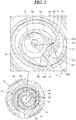
- FIG. 2 is a horizontal sectional view of a compression unit in FIG. 1 .
- a lower compression type scroll compressor may be provided with a motor unit 20 having a driving motor within a casing 10 to generate a rotational force, and a compression unit 30 located below the motor unit 20 and having a predetermined space (hereinafter, referred to as an intermediate space) 10a to compress refrigerant by receiving the rotational force of the motor unit 20.
- a motor unit 20 having a driving motor within a casing 10 to generate a rotational force
- a compression unit 30 located below the motor unit 20 and having a predetermined space (hereinafter, referred to as an intermediate space) 10a to compress refrigerant by receiving the rotational force of the motor unit 20.
- the casing 10 may include a cylindrical shell 11 forming a hermetic container, an upper shell 12 forming the hermetic container by covering an upper portion of the cylindrical shell 11, and a lower shell 13 forming the hermetic container by covering a lower portion of the cylindrical shell 11 and simultaneously forming an oil storage space 10c.
- a refrigerant suction pipe 15 may directly communicate with a suction chamber of the compression unit 30 through a lateral surface of the cylindrical shell 11, and a refrigerant discharge pipe 16 communicating with an upper space 10b of the casing 10 may be provided through a top of the upper shell 12.
- the refrigerant discharge pipe 16 may correspond to a path through which compressed refrigerant discharged from the compression unit 30 to the upper space 10b of the casing 10 is discharged to outside.
- the refrigerant discharge pipe 16 may be inserted up to a middle of the upper space 10b of the casing 10 to allow the upper space 10b to form a kind of oil separation space.
- an oil separator (not shown) for separating oil mixed with refrigerant may be connected to the refrigerant suction pipe 15 within the casing 10 including the upper space 10b or within the upper space 10b.
- the motor unit 20 may include a stator 21 and a rotor 22 rotating within the stator 21.
- the stator 21 is provided with teeth and slots forming a plurality of coil winding portions (not shown) on an inner circumferential surface thereof along a circumferential direction, such that a coil 25 is wound therearound.
- a second discharge passage PG2 is formed by combining a gap between the inner circumferential surface of the stator 21 and an outer circumferential surface of the rotor 22 with the coil winding portions.
- a plurality of D-cut faces 21a are formed on an outer circumferential surface of the stator 21 along the circumferential direction.
- the plurality of D-cut faces 21a may form a first oil passage PO1 together with an inner circumferential surface of the cylindrical shell 11 to allow a flow of oil.
- oil separated from refrigerant in the upper space 10b flows to the lower space 10c through the first oil passage PO1 and a second oil passage PO2 which will be described later.
- a frame 31 forming the compression unit 30 may be fixedly coupled to an inner circumferential surface of the casing 10 with a predetermined interval below the stator 21.
- An outer circumferential surface of the frame 31 may be shrink-fitted to or fixedly welded on an inner circumferential surface of the cylindrical shell 11.
- a frame-side partition wall portion 311 may be formed in an annular shape on an edge of the frame 31.
- the frame-side partition wall portion 311 may be provided with a plurality of frame-side discharge holes 311a formed axially in a penetrating manner to form a first discharge passage PG1 together with scroll-side discharge holes 322a of a first scroll 32 to be explained later.
- a plurality of oil collecting grooves 311b may be formed on an outer circumferential surface of the frame-side partition wall portion 311 in a circumferential direction.
- the frame-side oil collecting grooves 311b form a second oil passage PO2 together with scroll-side oil collecting grooves 322b of the first scroll to be explained later.
- a first shaft receiving protrusion 312 for supporting a main bearing portion 51 of a rotating shaft 50 which will be described later may be formed in a central portion of the frame 31, and a first shaft receiving hole 312a may be formed through the first shaft receiving protrusion 312 so that the main bearing portion 51 of the rotating shaft 50 is rotatably inserted therein so as to be supported in a radial direction.
- a fixed scroll hereinafter, referred to as a first scroll
- a second scroll which is eccentrically connected to the rotating shaft 50.
- the first scroll 32 may be fixedly coupled to the frame 31, but may alternatively be movably coupled to the frame 31 in the axial direction.
- the first scroll 32 may be provided with a fixed-side disk portion 321 formed in a substantially disk shape, and a scroll-side sidewall portion 322 formed at an edge of the fixed-side disk portion 321 and coupled to a lower edge of the frame 31.
- a suction port 324 through which a refrigerant suction pipe 15 and a suction chamber communicate with each other may be formed through one side (or portion) of the scroll-side sidewall portion 322, and a discharge port 325a, 325b which communicates with a discharge chamber and through which compressed refrigerant is discharged may be formed through a central portion of the fixed-side disk portion 321.
- the discharge port 325a, 325b may be provided by one in number so as to communicate with both of the first compression chamber V1 and the second compression chamber V2 to be described later, but may also be provided in plurality to independently communicate with the compression chambers V1 and V2.
- the scroll-side sidewall portion 322 is provided with a plurality of scroll-side discharge holes 322a communicating with the frame-side discharge holes 311a so as to form the first discharge passage PG1 together with the frame-side discharge holes 311a.
- the scroll-side sidewall portion 322 may be provided with the scroll-side oil collecting groove 322b formed on an outer circumferential surface thereof.
- the scroll-side oil collecting groove 322b communicates with the frame-side oil collecting groove 311b so as to form a second oil passage PO2 together with the frame-side oil collecting groove 311b. Accordingly, oil collected may be guided into the lower space 10c along the second oil passage PO2.
- a discharge cover 34 for guiding refrigerant discharged from the compression chamber Vc to a passage guide which will be described later may be coupled to a lower side of the first scroll 32.
- the discharge cover 34 may be formed in a manner that a discharge space Vd thereof to be explained later can receive the discharge ports 325a, 325b and simultaneously receive an inlet of the first discharge passage PG1 for guiding refrigerants discharged from the compression chamber Vc through the discharge ports 325a, 325b to the upper space 10b of the casing 10, more particularly, a space between the motor unit 20 and the compression unit 30.
- the discharge cover will be described later together with the discharge passage.
- a fixed wrap 323 forming the compression chamber Vc in engagement with an orbiting wrap 332 which will be described later may be formed on an upper surface of the fixed-side disk portion 321.
- the fixed wrap 323 will be described later together with the orbiting wrap 332.
- a second shaft receiving protrusion 326 for supporting a sub bearing 52 of a rotating shaft 50 which will be described later may be formed in the center of the fixed-side disk portion 321, and a second shaft receiving hole 326a for supporting the sub bearing 52 in a radial direction may be formed through the second shaft receiving protrusion 326 in an axial direction.
- the second scroll 33 may be provided with an orbiting-side disk portion 331 formed in a substantially disk shape.
- the orbiting wrap 332 forming a compression chamber in engagement with the fixed wrap 331 may be formed on a lower surface of the orbiting-side disk portion 331.
- the orbiting wrap 332 may be formed in an involute shape together with the fixed wrap 323, but may also be formed in various other shapes.
- the orbiting wrap 332 may have a shape in which a plurality of arcs having different diameters and origins are connected, and the outermost curve may be formed in a substantially elliptical shape having a major axis and a minor axis.
- the fixed wrap 323 may be formed in a similar manner.
- a rotating shaft coupling portion 333 which forms an inner end portion of the orbiting wrap 332 and in which an eccentric portion 53 of the rotating shaft 50 to be described later is rotatably inserted may be formed through a central portion of the orbiting-side disk portion 331 in an axial direction.
- An outer circumferential portion of the rotating shaft coupling portion 333 is connected to the orbiting wrap 332 to form the compression chamber Vc together with the fixed wrap 322 during a compression process.
- the rotating shaft coupling portion 333 may be formed at a height overlapping the orbiting wrap 332 on the same plane, and thus the eccentric portion 53 of the rotating shaft 50 may be formed at a height overlapping the orbiting wrap 332 on the same plane. Accordingly, repulsive force and compressive force of refrigerant are attenuated by each other while being applied to the same plane based on the orbiting-side disk portion, thereby preventing an inclination of the second scroll 33 due to an action of the compressive force and repulsive force.
- the rotating shaft coupling portion 333 is provided with a concave portion 335 formed on an outer circumferential portion facing an inner end portion of the fixed wrap 323 and engaged with a protruding portion 328 of the fixed wrap 323 which will be described later.
- an increasing portion 335a is formed on an upstream side along a forming direction of the compression chamber Vc to increase a thickness from an inner circumferential portion to an outer circumferential portion of the rotating shaft coupling portion 333.
- This may extend a compression path of the first compression chamber V1 immediately before discharge, and consequently the compression ratio of the first compression chamber V1 can be increased to be close to a pressure ratio of the second compression chamber V2.
- the first compression chamber V1 is a compression chamber formed between an inner surface of the fixed wrap 323 and an outer surface of the orbiting wrap 332, and will be described later separately from the second compression chamber V2.
- an arcuate compression surface 335b having an arcuate shape.
- a diameter of the arcuate compression surface 335b is decided by a thickness of an inner end portion of the fixed wrap 323 (i.e., a thickness of a discharge end) and an orbiting radius of the orbiting wrap 332.
- a thickness of the arcuate compression surface 335b increases.
- a thickness of the orbiting wrap around the arcuate compression surface 335b may increase to ensure durability, and the compression path may extend to increase the compression ratio of the second compression chamber V2 to that extent.
- the protruding portion 328 protruding toward the outer circumferential portion of the rotating shaft coupling portion 333 may be formed adjacent to an inner end portion (a suction end or starting end) of the fixed wrap 323 corresponding to the rotating shaft coupling portion 333.
- the protruding portion 328 may be provided with a contact portion 328a protruding therefrom and engaged with the concave portion 335.
- the inner end portion of the fixed wrap 323 may be formed to have a larger thickness than other portions.
- the compression chamber Vc may be formed between the fixed-side disk portion 321 and the fixed wrap 323 and the orbiting wrap 332 and the orbiting-side disk portion 331, and a suction chamber, an intermediate pressure chamber, and a discharge chamber may be formed consecutively along a proceeding direction of the wraps.
- the compression chamber Vc may include the first compression chamber V1 formed between an inner surface of the fixed wrap 323 and an outer surface of the orbiting wrap 332, and the second compression chamber V2 formed between an outer surface of the fixed wrap 323 and an inner surface of the orbiting wrap 332.
- the first compression chamber V1 includes a compression chamber formed between two contact points P11 and P12 generated in response to the inner surface of the fixed wrap 323 being brought into contact with the outer surface of the orbiting wrap 332, and the second compression chamber V2 includes a compression chamber formed between two contact points P21 and P22 generated in response to the outer surface of the fixed wrap 323 being brought into contact with the inner surface of the orbiting wrap 332.
- a large angle of angles formed between two lines, which connect a center of the eccentric portion, namely, a center O of the rotation shaft coupling portion to the two contact points P11 and P12, respectively, is defined as a within the first compression chamber V2 just before discharge
- the angle a at least just before the discharge is larger than 360° (i.e., a ⁇ 360° )
- a distance l between normal vectors at the two contact points P11, P12 also has a value greater than zero.
- the first compression chamber immediately before the discharge may have a smaller volume as compared to a case where a fixed wrap and an orbiting wrap have a shape of an involute curve. Therefore, the compression ratios of the first and second compression chambers V1 and V2 can all be improved even without increasing the sizes of the fixed wrap 323 and the orbiting wrap 332.
- the second scroll 33 may be orbitally provided between the frame 31 and the fixed scroll 32.
- An Oldham ring 35 for preventing rotation of the second scroll 33 may be provided between an upper surface of the second scroll 33 and a lower surface of the frame 31, and a sealing member 36 for forming a back pressure chamber S1 to be explained later may be provided at an inner side rather than the Oldham ring 35.
- An intermediate pressure space is formed on an outside of the sealing member 36.
- the intermediate pressure space communicates with an intermediate compression chamber Vc and thus is filled with refrigerant of intermediate pressure, so as to serve as a back pressure chamber. Therefore, a back pressure chamber formed at an inside with respect to the sealing member 36 may be referred to as a first back pressure chamber S1, and an intermediate pressure space formed at an outside may be referred to as a second back pressure chamber S2.
- the back pressure chamber S1 is a space formed by a lower surface of the frame 31 and an upper surface of the second scroll 33 based on the sealing member 36.
- an upper portion of the rotating shaft 50 is press-fitted into the center of the rotor 22 while a lower portion thereof is coupled to the compression unit 30 to be supported in the radial direction. Accordingly, the rotating shaft 50 transfers the rotational force of the motor unit 20 to the orbiting scroll 33 of the compression unit 30. Then, the second scroll 33 eccentrically coupled to the rotating shaft 50 performs an orbiting motion with respect to the first scroll 32.
- a main bearing (hereinafter, referred to as a first bearing) 51 may be formed at a lower portion of the rotating shaft 50 to be inserted into the first bearing hole 312a of the frame 31 and supported in a radial direction
- a sub-bearing (hereinafter, referred to as a second bearing) 52 may be formed at a lower side of the first bearing 51 to be inserted into the second bearing hole 326a of the first scroll 32 and supported in a radial direction.
- the eccentric portion 53 may be provided between the first bearing 51 and the second bearing 52 in a manner of being inserted into the rotating shaft coupling portion 333.
- the first bearing 51 and the second bearing 52 may be coaxially formed to have the same axial center, and the eccentric portion 53 may be eccentrically formed in the radial direction with respect to the first bearing 51 or the second bearing 52.
- the second bearing 52 may be eccentrically formed with respect to the first bearing 51.
- an oil supply passage 50a for supplying oil to each bearing and the eccentric portion may be formed within the rotating shaft 50 along the axial direction.
- the oil supply passage 50a may be formed from a lower end of the rotating shaft 50 to approximately a lower end or a middle height of the stator 21 or a position higher than an upper end of the first bearing 31 in a grooving manner.
- the oil supply passage 50a may also be formed by penetrating through the rotating shaft 50 in an axial direction.
- an oil feeder 60 for pumping up oil filled in the lower space 10c may be coupled to the lower end of the rotating shaft 50, namely, a lower end of the second bearing 52.
- the oil feeder 60 may include an oil supply pipe 61 inserted into the oil supply passage 50a of the rotating shaft 50, and a blocking member 62 for blocking an introduction of foreign materials by receiving the oil supply pipe 61 therein.
- the oil supply pipe 61 may be located to be immersed in oil of the lower space 10c through the discharge cover 34.
- the passage separation unit 40 is provided in the intermediate space (hereinafter, referred to as a first space) 10a, which is a via space formed between a lower surface of the motor unit 20 and an upper surface of the compression unit 30, to play the role of preventing refrigerant discharged from the compression unit 30 from interfering with oil flowing from the upper space (hereinafter, referred to as a second space) 10b of the motor unit 20 which is an oil separation space to the lower space (hereinafter, referred to as a third space) 10c of the compression unit 30 which is an oil storage space.
- a first space 10a which is a via space formed between a lower surface of the motor unit 20 and an upper surface of the compression unit 30, to play the role of preventing refrigerant discharged from the compression unit 30 from interfering with oil flowing from the upper space (hereinafter, referred to as a second space) 10b of the motor unit 20 which is an oil separation space to the lower space (hereinafter, referred to as a third space) 10c of the
- the passage separation unit 40 includes a passage guide which divides the first space 10a into a space (hereinafter, referred to as a refrigerant flowing space) in which refrigerant flows, and a space (hereinafter, referred to as an oil flowing space) in which oil flows.
- the passage guide may include a first passage guide 410 protruding upward in the axial direction from the upper surface of the frame, a second passage guide 420 protruding downward in the axial direction from the lower surface of the driving motor 20, and a sealing portion 430 provided between the first and second passage guides 410 and 420 to seal a gap between an inner space and an outer space of the passage guide.
- Each of the first passage guide 410 and the second passage guide 420 may be provided with a single annular wall portion or a plurality of annular wall portions.
- the second passage guide 420 may be assembled to the stator 21 of the driving motor 20 or extend from an insulator coupled to the stator 21.
- the sealing portion may be an O-ring interposed between an inner surface of the first passage guide 410 and an outer surface of the second passage guide 420 facing the inner surface of the first passage guide 410.
- the sealing portion may alternatively be formed by coupling the first passage guide 410 and the second passage guide 420 in a concave-convex manner or a stepped manner.
- An upper end of the first passage guide 410 or a lower end of the second passage guide 420 may be closely adhered on or inserted into the stator 21 or the frame 31. In this case, one passage guide may be provided.
- unexplained reference numeral 70 denotes an oil separation unit
- 80 denotes an accumulator
- a lower compression type scroll compressor according to the present embodiment operates as follows.
- refrigerant supplied from an outside of the casing 10 through the refrigerant suction pipe 15 is introduced into the compression chamber Vc, and compressed as a volume of the compression chamber Vc is reduced by the orbiting motion of the orbiting scroll 33.
- the refrigerant is then discharged into an inner space of the discharge cover 34 through the first discharge port 325a and the second discharge port 325b.
- noise is reduced from the refrigerant discharged into the inner space of the discharge cover 34 while the refrigerant circulates within the inner space of the discharge cover 34.
- the noise-reduced refrigerant flows to a space between the frame 31 and the stator 21, and then is introduced into an upper space of the motor unit 20 through a gap between the stator 21 and the rotor 22.
- Oil is separated from the refrigerant in the upper space 10b of the casing 10. Accordingly, the refrigerant is discharged out of the casing 10 through the refrigerant discharge pipe 16, while the oil is collected back into the lower space 10c as the oil storage space of the casing 10 through a passage between the inner circumferential surface of the casing 10 and the stator 21 and a passage between the inner circumferential surface and the outer circumferential surface of the compression unit 30.
- the passage separation unit 40 is provided between the motor unit and the frame to separate a discharge passage, through which refrigerant and oil are discharge, from an oil passage for collecting or recovering oil separated from refrigerant in the upper space 10b into the lower space 10c. Accordingly, the refrigerant and the oil can be discharged and collected without being mixed with each other.
- the discharge cover 34 serves to reduce pressure pulsation of refrigerant and oil discharged through the discharge port 325 and simultaneously to connect the discharge port 325 and the first discharge passage PG1. Therefore, an inner volume of the discharge cover 34, namely, a volume of the discharge space Vd is closely related to efficiency of the compressor.
- the effect of reducing the pressure pulsation may be reduced by half, and even the narrow volume of the discharge space Vd may act as a kind of flow resistance, which may result in lowering efficiency of the compressor.
- the volume of the discharge space Vd is larger than a proper value, pressure pulsation can be lowered and flow resistance to the discharged refrigerant and oil can be reduced, so that the refrigerant can smoothly move to the inner space of the casing 10. Therefore, it is important to optimize the volume of the discharge space Vd in the aspect of improving the efficiency of the compressor.
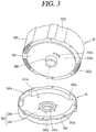
- FIG. 3 is a perspective view illustrating a fixed scroll and a discharge cover detached from a compression unit in accordance with an embodiment of the present invention
- FIG. 4 is an enlarged sectional view illustrating a compression unit in accordance with an embodiment of the present invention
- FIG. 5 is a sectional view taken along the line "IV-IV" of FIG. 4 .
- the discharge cover 34 is formed in a cap-like shape and includes a housing portion 341 having a space part 341a forming a discharge space Vd together with the first scroll 32, and a flange portion 342 extending outward from an outer circumferential surface of the housing portion 341 and coupled to the first scroll 32.
- the housing portion 341 may include a first surface 345 formed substantially flat to form a bottom surface, and a second surface 346 extending axially from the first surface 345 in a substantially annular shape to form a side wall surface. Accordingly, the first surface 345 and the second surface 346 form the space part 341a for accommodating a lower end of the discharge port 325 and a lower end of the scroll-side discharge hole 322a, and the space part 341a forms the discharge space Vd together with a surface of the first scroll 32 inserted into the space part 341a.
- a through hole 345a is formed through a central portion of the first surface 345.
- the through hole 345a is inserted to a second shaft receiving protrusion 326, which protrudes downward (axially) from the rear surface of the first scroll 32, namely, from the fixed-side disk portion 321.
- a sealing member (not shown) for sealing a gap between an inner circumferential surface of the through hole 345a and an outer circumferential surface of the second shaft receiving protrusion 326 may be formed on the inner circumferential surface of the through hole 345a.
- At least one discharge guide groove 346a may be formed in the second surface 346 along a circumferential direction.
- the discharge guide groove 346a may be formed to be recessed outward in a radial direction, and the scroll-side discharge hole 322a constituting the first discharge passage PG1 may be formed to be positioned inside the discharge guide groove 346a.
- the second surface 346 of the housing portion 341 excluding the discharge guide grooves 346a forms a kind of sealing portion as its inner surface is closely adhered on an outer circumferential surface of the first scroll 32, namely, an outer circumferential surface of the fixed-side disk portion 321.
- an entire circumferential angle ⁇ of the discharge guide groove 346a may be formed to be smaller than or equal to an entire circumferential angle with respect to the inner circumferential surface of the discharge space Vd except for the discharge guide grooves 346a.
- the inner circumferential surface of the discharge space Vd except for the discharge guide groove 346a can secure not only a sufficient sealing area but also a circumferential length for forming the flange portion 342 to be described later.
- the flange portion 342 may extend radially from an outer circumferential surface of a portion defining a sealing part, namely, a portion, excluding the discharge guide grooves 346a, of the second surface 346 of the housing portion 341.
- the flange portion 342 may be provided with coupling holes 342a for coupling the discharge cover 34 to the first scroll 32 with bolts, and a plurality of oil collecting grooves 342b formed between the neighboring coupling holes 342a in a circumferential direction.
- the third oil collecting grooves 342b may be formed to be recessed inward (toward a center) from an outer circumferential surface of the flange portion 342 in a radial direction.
- the discharge space Vd provided in the discharge cover 34 must be formed to have a predetermined volume or more in consideration of the pressure pulsation, as described above, so that efficiency of the compressor can be increased. Therefore, the volume of the discharge space Vd may be proportional to a volume of the compression chamber Vc. If the volume of the compression chamber Vc is large, pressure pulsation of refrigerant discharged from the compression chamber Vc is large. Conversely, if the volume of the compression chamber Vc is small, the pressure pulsation of the refrigerant discharged from the compression chamber Vc becomes small.
- the volume of the discharge space Vd may be formed proportional to an area of the discharge port 325. However, since the area of the discharge port 325 is also proportional to the volume of the compression chamber Vc, the volume of the discharge space Vd may be suitably decided in proportion to the volume of the compression chamber Vc.
- the volume of the compression chamber Vc means the sum of the volumes of the two compression chambers.
- the compression chamber Vc of the scroll compressor is formed in a manner that an initial compression chamber is formed at an outer side, a final compression chamber is formed in a central side, and a continuously moving intermediate compression chamber is formed between the initial compression chamber and the final compression chamber.
- the volume of the compression chamber Vc refers to a volume of the initial compression chamber.
- FIG. 6 is a graph showing comparison results between a pulsation component and compressor efficiency according to a volume ratio in a discharge cover in accordance with an embodiment of the present invention.
- a value obtained by dividing the volume of the discharge space Vd by a total volume (stroke volume of the compressor) of the initial compression chamber Vc is referred to as a volume ratio, and the compressor efficiency is compared with a pulsation component on the basis of the volume ratio.
- the volume of the discharge space Vd is optimally set based on the comparison results.
- the pulsation component is drastically changed at a volume ratio of about 3.5 to 5.5. That is, in a region where the volume ratio is 3.5 to 5.5 or less, the pulsation component sharply drops as the volume ratio increases. On the other hand, in a region where the volume ratio exceeds 3.5 to 5.5, the drop is gradually reduced. Therefore, if the discharge volume is set so that the volume ratio is 3.5 to 5.5 or less, the pulsation component may not be sufficiently reduced. Therefore, the volume ratio may preferably set to be 3.5 to 5.5 or more in consideration of the pressure pulsation.
- the compressor efficiency is remarkably changed based on the volume ratio of 4 to 6. That is, in a region where the volume ratio is 4 to 6 or less, the efficiency of the compressor increases sharply as the volume ratio increases. On the other hand, in a region where the volume ratio exceeds 4 to 6, the increase is gradually slowed down. Therefore, if the discharge volume is set so that the volume ratio is 4 to 6 or less, the compressor efficiency may not be sufficiently improved. Therefore, the volume ratio may preferably set to be 4 to 6 or more in consideration of the compressor efficiency.
- the volume ratio may be set in consideration of both the pressure pulsation and the compressor efficiency.
- the volume ratio may be set to be about 3.5 to 6 or more, preferably, about 4.5 or more.
- an appropriate volume ratio can be calculated on the basis of the total volume of the initial compression chamber, and thus an optimal volume of the discharge space can be calculated, which may result in easily providing an appropriate size of the discharge cover in correspondence to capacity of the compressor.
- FIG. 7 is a graph showing comparison results of pressure pulsation (dynamic pressure) according to variation of a volume ratio in a scroll compressor in accordance with an embodiment of the present invention
- FIG. 8 is a table summarizing pulsation components and efficiencies for each size of a discharge volume and a volume of a compression chamber according to FIG. 7 .
- a dynamic pressure component is about 2.8 kgf/cm2 when the compressor operates at 120 Hz in a volume ratio of 2.6, but the dynamic pressure component is changed to about 2.0 kgf/cm2 at the volume ratio of 4.9, to about 1.2 kgf/cm2 at the volume ratio of 9.5, and to about 0.4 kgf/cm2 at the volume ratio of 14.0.
- a reduction ratio of the dynamic pressure component with respect to the volume ratio is the largest at around the volume ratio of 4.9.
- the dynamic pressure component is close to almost zero.
- an upper limit of the volume ratio can be set to 14.0.
- the compressor efficiency increases as the volume ratio increases.
- the compressor efficiency is increased by 0.17 when the volume ratio increases from 2.6 to 4.9, increased by 0.05 when the volume ratio increases from 4.9 to 9.5, and increased by 0.04 when the volume ratio increases from 9.5 to 14.0.
- the greatest increase of the compressor efficiency is seen when the volume ratio is about 4.9.
- the increase of the compressor efficiency is greatly slowed down while the volume ratio is increased from 9.5 to 14.0, it may be predicted that the compressor efficiency is not greatly improved but will be converged to a specific value even if the volume ratio increases more.
- limiting the upper limit value of the volume ratio may be preferable because an optimum compressor efficiency can be expected while appropriately maintaining the size of the compressor. Considering the test result, the upper limit value of the volume ratio can be set to about 15 or less.
- the discharge guide groove is formed on the inner wall surface of the discharge cover to be recessed outward along the radial direction, and the first discharge passage of the first scroll is accommodated in the discharge guide groove.
- the inner wall surface of the discharge cover excluding the discharge guide groove is brought into contact with the outer circumferential surface of the first scroll so as to form the sealing portion.
- FIG. 9 is a planar view illustrating another embodiment of a discharge cover according to the present invention.
- a space expansion groove 346b similar to the discharge guide groove 346a, is spaced apart from the outer circumferential surface of the first scroll 32, and is not brought into contact with the first scroll 32, thereby not forming a sealing portion. Since the scroll-side discharge hole 322a is not accommodated in the space expansion groove 346b, the space expansion groove 346b is a space formed to enlarge the volume of the discharge space Vd.
- the volume of the discharge space Vd can be enlarged and simultaneously an increase in depth (axial length) of the discharge cover 34 can be prevented, thereby securing an appropriate volume of the discharge space Vd and reducing the size of the compressor. Further, since the space expansion groove 346b also functions as a space for attenuating pressure pulsation, the pressure pulsation can be further reduced.
- FIG. 10 is an enlarged sectional view illustrating an inside of a discharge guide groove in a discharge cover in accordance with an embodiment of the present invention.
- the housing portion 341 of the discharge cover 34 may be provided with a first surface 345 forming a bottom surface and a second surface 346 extending from an outer circumferential surface of the first surface 345 to form a sidewall surface and having a flange portion 342 on an outer circumferential surface thereof.
- At least one discharge guide groove 346a may be formed on the second surface 346 in a manner of being recessed outward in a radial direction.
- the discharge guide groove 346a is formed to have a predetermined volume by the first surface 345 and the second surface 346, and a discharge guide surface 346c which is upwardly inclined to outside along a radial direction is formed at a point where the first surface 345 and the second surface 346 meet.
- the discharge guide surface 346c is formed to have an inclination angle of about 45° and the scroll-side discharge hole 322a is formed to be located within a range of the discharge guide surface 346c in an axial direction.
Landscapes
- Engineering & Computer Science (AREA)
- Mechanical Engineering (AREA)
- General Engineering & Computer Science (AREA)
- Rotary Pumps (AREA)
- Applications Or Details Of Rotary Compressors (AREA)
Abstract
Description
- The present invention relates to a scroll compressor, and more particularly, a compressor having a compression unit located below a motor unit.
- The scroll compressor is a compressor forming a compression chamber including a suction chamber, an intermediate pressure chamber, and a discharge chamber between both scrolls while the plurality of scrolls performs a relative orbiting motion in an engaged state. Such a scroll compressor may obtain a relatively high compression ratio as compared with other types of compressors while smoothly connecting suction, compression, and discharge strokes of refrigerant, thereby obtaining stable torque. Therefore, the scroll compressor is widely used for compressing refrigerant in an air conditioner or the like. Recently, a high-efficiency scroll compressor having a lower eccentric load and an operation speed at 180 Hz or higher has been introduced.
- Such a scroll compressor may be divided into an upper compression type and a lower compression type according to the positions of the driving unit and the compression unit. An upper compression type is configured such that a compression unit is located above a driving unit, whereas a lower compression type is configured such that a compression unit is located below a driving unit.
- Generally, in compressors including a high-pressure scroll compressor, a discharge pipe is disposed far away from a compression unit so that oil can be separated from refrigerant in an inner space of a casing. Therefore, an upper compression type high-pressure scroll compressor has a discharge pipe located between a motor unit and a compression unit, whereas a lower compression type high-pressure scroll compressor has a discharge pipe at an upper side of a motor unit.
- Accordingly, in an upper compression type, refrigerant discharged from a compression unit does not move up to a motor unit but moves toward a discharge pipe in an intermediate space between the motor unit and the compression unit. On the other hand, in a lower compression type, refrigerant discharged from a compression unit flows through a motor unit and moves toward a discharge pipe in an oil separation space formed at an upper side of the motor unit.
- In the lower compression type scroll compressor as described above, since the refrigerant should be discharged from the compression unit located at the lower side and move upward, a discharge cover is provided at a lower side of the compression unit to guide the refrigerant discharged from the compression unit upward. This is disclosed in the prior art, Korean Patent Publication No.
10-2016-0017993 (Published Date: February 17, 2016 - As described in the prior art, a discharge cover is hermetically coupled to a lower end of a fixed scroll, and the fixed scroll is provided with a scroll-side discharge passage communicating with a discharge space of the discharge cover, and the scroll-side discharge passage of the fixed scroll communicates with a frame-side discharge passage penetrating through an upper surface of a main frame. Accordingly, refrigerant discharged from a compression unit to the discharge space of the discharge cover sequentially passes through the scroll-side discharge passage and the frame-side discharge passage, so as to be guided into a space between a motor unit and the compression unit. The refrigerant flows through the motor unit and moves to an upper space.
- However, in the prior art lower compression scroll compressor as described above, pressure pulsation occurs as the refrigerant compressed in the compression unit is discharged into the discharge cover. The pressure pulsation interferes with smooth flow of the refrigerant into the discharge passage, thereby lowering compressor efficiency.
- In the related art lower compression type scroll compressor, although the pressure pulsation occurred in the discharge cover differs depending on compressor capacity, a discharge cover with an appropriate size corresponding to capacity of each compressor is not provided or is difficult to be provided, which causes a limit in improving the compressor efficiency.
- One aspect of the present invention is to provide a scroll compressor, capable of enhancing compressor efficiency by effectively reducing pressure pulsation of refrigerant discharged from a compression unit to a discharge cover.
- Another object of the present invention is to provide a scroll compressor, capable of easily providing a discharge cover with an appropriate size corresponding to capacity of a compressor.
- Still another object of the present invention is to provide a scroll compressor, capable of enhancing compressor efficiency without excessively increasing a size of the compressor by optimizing a volume of a discharge space with respect to a stroke volume of the compressor.
- In order to achieve the aspects and other advantages of the present invention, there is provided a scroll compressor, configured such that a compression unit having compression chambers is provided below a motor unit, discharge passages are provided in the compression unit and the motor unit to guide discharged refrigerant to an upper side of the motor unit, and a discharge cover forming a discharge space is provided at a lower portion of the compression unit to guide refrigerant discharged from the compression chambers to the discharge passages, wherein a volume of the discharge space changes in proportion to a suction volume of the compression chamber.
- Here, the volume of the discharge space may be determined by comparing pressure pulsation in the discharge space with compressor efficiency based on a value obtained by dividing the volume of the discharge space by a total volume of an initial compression chamber of the compression chambers.
- The volume of the discharge space may have a value of 4.5 or more, and the value may be obtained by dividing the volume of the discharge space by the volume of the initial compression chamber.
- Also, in order to achieve the aspects and other advantages of the present invention, there is provided a scroll compressor, including a casing, a driving motor fixed to an inner space of the casing and having an inner passage and an outer passage penetratingly formed in an axial direction, a rotating shaft coupled to the driving motor to be rotatable, a frame provided below the driving motor with a space therebetween and supporting the rotating shaft inserted therethrough, a first scroll provided on a lower side of the frame and having a fixed wrap formed on one surface thereof, a second scroll provided between the frame and the first scroll, having an orbiting wrap engaged with the fixed wrap, and having the rotating shaft eccentrically coupled thereto in a manner of overlapping the orbiting wrap in a radial direction, the second scroll forming compression chambers together with the first scroll while performing an orbiting motion with respect to the first scroll, a discharge port provided in the first scroll, a discharge passage formed through the first scroll, and a discharge cover coupled to the first scroll, and having a space part for accommodating an end portion of the discharge port and an end portion of the discharge passage so that the refrigerant discharged through the discharge port is guided to the discharge passage, wherein the space part of the discharge cover has a discharge space defined therein by the first scroll, and the discharge space has a volume of 4.5 or more, a value obtained by dividing the volume of the discharge space by a stroke volume defined as a total volume of the initial compression chamber among the compression chambers.
- Here, the discharge cover may be coupled to the first scroll in a manner that an inner circumferential surface thereof constituting the discharge space is inserted into an outer circumferential surface of the first scroll, and the discharge cover may be provided with at least one discharge guide groove recessed in the inner circumferential surface thereof toward an outer circumferential surface along a circumferential direction, and spaced apart from the outer circumferential surface of the first scroll.
- The discharge passage may be formed in a range of the discharge guide groove.
- The discharge guide groove may be provided with at least one space expansion groove formed on one surface thereof in the circumferential direction, and the discharge passage may be formed out of a range of the space expansion groove.
- The discharge guide groove may have an entire circumferential angle smaller than or equal to an entire circumferential angle with respect to an inner circumferential surface of the discharge space excluding the discharge guide groove.
- The discharge guide groove may be provided with a guide surface that is inclined in a direction toward a radial side surface forming the discharge guide groove.
- Here, the discharge cover may include a housing portion forming a discharge space, and a flange portion extending from an outer circumferential surface of the housing portion and coupled to the first scroll. The housing portion may be provided with at least one discharge guide groove recessed outward in a side wall surface thereof along the circumferential direction, and the discharge passage may be located inside the discharge guide groove.
- The housing portion may be provided with a sealing portion on a portion, except for the discharge guide groove, of the side wall surface thereof, and the sealing portion may be closely adhered on the outer circumferential surface of the first scroll. The flange portion extending from an outer circumferential surface of the sealing portion may be provided with an oil collecting groove recessed in an outer circumferential surface thereof toward a center by a predetermined depth.
- The first scroll and the frame may be provided with oil passages communicating spaces of both sides in an axial direction of the first scroll and the frame, and the oil passages may communicate with the oil collecting groove.
- The frame and the driving motor may be provided with a passage separation unit therebetween, and the passage separation unit may be provided between the discharge passage and the oil passage in a radial direction.
- The passage separation unit may include a first passage guide extending from the frame, a second passage guide extending from the driving motor, and a sealing portion provided between the first passage guide and the second passage guide.
- In order to achieve the aspects and other advantages of the present invention, there is provided a scroll compressor, including a casing having an inner space in which oil is stored, a driving motor provided in the inner space of the casing, a rotating shaft coupled to the driving motor, a frame provided at one side of the driving motor and having a frame-side discharge passage formed therethrough in an axial direction, a first scroll having a discharge port formed at one side of the frame and having a scroll-side discharge passage formed therethrough in an axial direction so as to communicate with a frame-side discharge passage, a second scroll provided between the frame and the first scroll, forming compression chambers together with the first scroll while performing an orbiting motion with respect to the first scroll, the compression chambers including an initial compression chamber formed at an outer side, a final compression chamber formed at an inner side, and at least one intermediate compression chamber between the initial compression chamber and the final compression chamber, and a discharge cover coupled to the first scroll, and having a space part for accommodating an end portion of the discharge port and an end portion of the discharge passage so that the refrigerant discharged through the discharge port is guided to the discharge passage, wherein the discharge space has a volume defined in the space part of the discharge cover by the first scroll, and the volume is larger than an entire volume of the first compression chamber.
- The discharge space may have a volume ratio of 4.5 or more under assumption that the volume ratio is a value obtained by dividing the volume of the discharge space by the entire volume of the initial compression chamber.
- The volume ratio may be 15 or less.
- A scroll compressor according to the present invention can set an appropriate inner volume of a discharge cover which guides refrigerant discharged from a compression unit to a discharge passage, thereby lowering pulsation pressure of the refrigerant discharged from the compression unit and improving efficiency of the compressor accordingly.
- In a scroll compressor according to the present invention, an inner volume of a discharge cover cam be designed in proportion to a stroke volume of the compressor, which can allow an appropriate inner volume of the discharge cover to be easily provided in correspondence with capacity of the compressor, which may result in standardizing a design of a compressor of high efficiency.
- Furthermore, as an inner volume of a discharge cover can be set properly, compressor efficiency can be improved while maintaining an appropriate size of the compressor.
-
-
FIG. 1 is a longitudinal sectional view of a lower compression-type scroll compressor in accordance with the present invention. -
FIG. 2 is a horizontal sectional view of a compression unit inFIG. 1 . -
FIG. 3 is a perspective view illustrating a fixed scroll and a discharge cover detached from a compression unit in accordance with an embodiment of the present invention. -
FIG. 4 is an enlarged sectional view illustrating a compression unit in accordance with an embodiment of the present invention. -
FIG. 5 is a sectional view taken along the line "IV-IV" ofFIG. 4 . -
FIG. 6 is a graph showing comparison results between a pulsation component and compressor efficiency according to a volume ratio in a discharge cover in accordance with an embodiment of the present invention. -
FIG. 7 is a graph showing comparison results of pressure pulsation (dynamic pressure) according to variation of a volume ratio in a scroll compressor in accordance with an embodiment of the present invention. -
FIG. 8 is a table summarizing pulsation components and efficiencies for each size of a discharge volume and a volume of a compression chamber according toFIG. 7 . -
FIG. 9 is a planar view illustrating another embodiment of a discharge cover according to the present invention. -
FIG. 10 is an enlarged sectional view illustrating an inside of a discharge guide groove in a discharge cover in accordance with an embodiment of the present invention. - Description will now be given in detail of a scroll compressor according to exemplary embodiments disclosed herein, with reference to the accompanying drawings. Hereinafter, for the sake of explanation, description will be given of a type of scroll compressor in which a rotating shaft overlaps an orbiting wrap on the same plane in a lower compression-type scroll compressor having a compression unit located lower than a motor unit. This type of scroll compressor is known to be suitable for application to a refrigeration cycle under high temperature and high compression ratio conditions.
-
FIG. 1 is a longitudinal sectional view of a lower compression-type scroll compressor in accordance with the present invention, andFIG. 2 is a horizontal sectional view of a compression unit inFIG. 1 . - Referring to those drawings, a lower compression type scroll compressor according to the present embodiment may be provided with a
motor unit 20 having a driving motor within acasing 10 to generate a rotational force, and acompression unit 30 located below themotor unit 20 and having a predetermined space (hereinafter, referred to as an intermediate space) 10a to compress refrigerant by receiving the rotational force of themotor unit 20. - The
casing 10 may include acylindrical shell 11 forming a hermetic container, anupper shell 12 forming the hermetic container by covering an upper portion of thecylindrical shell 11, and alower shell 13 forming the hermetic container by covering a lower portion of thecylindrical shell 11 and simultaneously forming anoil storage space 10c. - A
refrigerant suction pipe 15 may directly communicate with a suction chamber of thecompression unit 30 through a lateral surface of thecylindrical shell 11, and arefrigerant discharge pipe 16 communicating with anupper space 10b of thecasing 10 may be provided through a top of theupper shell 12. Therefrigerant discharge pipe 16 may correspond to a path through which compressed refrigerant discharged from thecompression unit 30 to theupper space 10b of thecasing 10 is discharged to outside. Therefrigerant discharge pipe 16 may be inserted up to a middle of theupper space 10b of thecasing 10 to allow theupper space 10b to form a kind of oil separation space. Furthermore, according to circumstances, an oil separator (not shown) for separating oil mixed with refrigerant may be connected to therefrigerant suction pipe 15 within thecasing 10 including theupper space 10b or within theupper space 10b. - The
motor unit 20 may include astator 21 and arotor 22 rotating within thestator 21. Thestator 21 is provided with teeth and slots forming a plurality of coil winding portions (not shown) on an inner circumferential surface thereof along a circumferential direction, such that a coil 25 is wound therearound. A second discharge passage PG2 is formed by combining a gap between the inner circumferential surface of thestator 21 and an outer circumferential surface of therotor 22 with the coil winding portions. As a result, refrigerant discharged into theintermediate space 10a between themotor unit 20 and thecompression unit 30 through a first discharge passage PG1 which will be described later flows to theupper space 10b formed above themotor unit 20 through the second discharge passage PG2 formed in themotor unit 20. - Furthermore, a plurality of D-cut faces 21a are formed on an outer circumferential surface of the
stator 21 along the circumferential direction. The plurality of D-cut faces 21a may form a first oil passage PO1 together with an inner circumferential surface of thecylindrical shell 11 to allow a flow of oil. As a result, oil separated from refrigerant in theupper space 10b flows to thelower space 10c through the first oil passage PO1 and a second oil passage PO2 which will be described later. - A
frame 31 forming thecompression unit 30 may be fixedly coupled to an inner circumferential surface of thecasing 10 with a predetermined interval below thestator 21. An outer circumferential surface of theframe 31 may be shrink-fitted to or fixedly welded on an inner circumferential surface of thecylindrical shell 11. - A frame-side
partition wall portion 311 may be formed in an annular shape on an edge of theframe 31. The frame-sidepartition wall portion 311 may be provided with a plurality of frame-side discharge holes 311a formed axially in a penetrating manner to form a first discharge passage PG1 together with scroll-side discharge holes 322a of afirst scroll 32 to be explained later. - A plurality of
oil collecting grooves 311b may be formed on an outer circumferential surface of the frame-sidepartition wall portion 311 in a circumferential direction. The frame-sideoil collecting grooves 311b form a second oil passage PO2 together with scroll-sideoil collecting grooves 322b of the first scroll to be explained later. - In addition, a first
shaft receiving protrusion 312 for supporting a main bearing portion 51 of arotating shaft 50 which will be described later may be formed in a central portion of theframe 31, and a first shaft receiving hole 312a may be formed through the firstshaft receiving protrusion 312 so that the main bearing portion 51 of therotating shaft 50 is rotatably inserted therein so as to be supported in a radial direction. - Furthermore, a fixed scroll (hereinafter, referred to as a first scroll) 32 may be provided on a lower surface of the
frame 31 with interposing therebetween an orbiting scroll (hereinafter, referred to as a second scroll) 33 which is eccentrically connected to therotating shaft 50. Thefirst scroll 32 may be fixedly coupled to theframe 31, but may alternatively be movably coupled to theframe 31 in the axial direction. - On the other hand, the
first scroll 32 may be provided with a fixed-side disk portion 321 formed in a substantially disk shape, and a scroll-side sidewall portion 322 formed at an edge of the fixed-side disk portion 321 and coupled to a lower edge of theframe 31. - A
suction port 324 through which arefrigerant suction pipe 15 and a suction chamber communicate with each other may be formed through one side (or portion) of the scroll-side sidewall portion 322, and adischarge port side disk portion 321. Thedischarge port - The scroll-
side sidewall portion 322 is provided with a plurality of scroll-side discharge holes 322a communicating with the frame-side discharge holes 311a so as to form the first discharge passage PG1 together with the frame-side discharge holes 311a. - The scroll-
side sidewall portion 322 may be provided with the scroll-sideoil collecting groove 322b formed on an outer circumferential surface thereof. The scroll-sideoil collecting groove 322b communicates with the frame-sideoil collecting groove 311b so as to form a second oil passage PO2 together with the frame-sideoil collecting groove 311b. Accordingly, oil collected may be guided into thelower space 10c along the second oil passage PO2. - Furthermore, a
discharge cover 34 for guiding refrigerant discharged from the compression chamber Vc to a passage guide which will be described later may be coupled to a lower side of thefirst scroll 32. Thedischarge cover 34 may be formed in a manner that a discharge space Vd thereof to be explained later can receive thedischarge ports discharge ports upper space 10b of thecasing 10, more particularly, a space between themotor unit 20 and thecompression unit 30. The discharge cover will be described later together with the discharge passage. - Furthermore, a fixed
wrap 323 forming the compression chamber Vc in engagement with anorbiting wrap 332 which will be described later may be formed on an upper surface of the fixed-side disk portion 321. The fixedwrap 323 will be described later together with theorbiting wrap 332. - In addition, a second
shaft receiving protrusion 326 for supporting a sub bearing 52 of arotating shaft 50 which will be described later may be formed in the center of the fixed-side disk portion 321, and a secondshaft receiving hole 326a for supporting the sub bearing 52 in a radial direction may be formed through the secondshaft receiving protrusion 326 in an axial direction. - On the other hand, the
second scroll 33 may be provided with an orbiting-side disk portion 331 formed in a substantially disk shape. Theorbiting wrap 332 forming a compression chamber in engagement with the fixedwrap 331 may be formed on a lower surface of the orbiting-side disk portion 331. - The
orbiting wrap 332 may be formed in an involute shape together with the fixedwrap 323, but may also be formed in various other shapes. For example, as illustrated inFIG. 2 , theorbiting wrap 332 may have a shape in which a plurality of arcs having different diameters and origins are connected, and the outermost curve may be formed in a substantially elliptical shape having a major axis and a minor axis. The fixedwrap 323 may be formed in a similar manner. - A rotating
shaft coupling portion 333 which forms an inner end portion of theorbiting wrap 332 and in which aneccentric portion 53 of therotating shaft 50 to be described later is rotatably inserted may be formed through a central portion of the orbiting-side disk portion 331 in an axial direction. - An outer circumferential portion of the rotating
shaft coupling portion 333 is connected to theorbiting wrap 332 to form the compression chamber Vc together with the fixedwrap 322 during a compression process. - Furthermore, the rotating
shaft coupling portion 333 may be formed at a height overlapping the orbiting wrap 332 on the same plane, and thus theeccentric portion 53 of therotating shaft 50 may be formed at a height overlapping the orbiting wrap 332 on the same plane. Accordingly, repulsive force and compressive force of refrigerant are attenuated by each other while being applied to the same plane based on the orbiting-side disk portion, thereby preventing an inclination of thesecond scroll 33 due to an action of the compressive force and repulsive force. - In addition, the rotating
shaft coupling portion 333 is provided with aconcave portion 335 formed on an outer circumferential portion facing an inner end portion of the fixedwrap 323 and engaged with a protrudingportion 328 of the fixedwrap 323 which will be described later. At one side of theconcave portion 335, an increasingportion 335a is formed on an upstream side along a forming direction of the compression chamber Vc to increase a thickness from an inner circumferential portion to an outer circumferential portion of the rotatingshaft coupling portion 333. This may extend a compression path of the first compression chamber V1 immediately before discharge, and consequently the compression ratio of the first compression chamber V1 can be increased to be close to a pressure ratio of the second compression chamber V2. The first compression chamber V1 is a compression chamber formed between an inner surface of the fixedwrap 323 and an outer surface of theorbiting wrap 332, and will be described later separately from the second compression chamber V2. - At another side of the
concave portion 335 is formed anarcuate compression surface 335b having an arcuate shape. A diameter of thearcuate compression surface 335b is decided by a thickness of an inner end portion of the fixed wrap 323 (i.e., a thickness of a discharge end) and an orbiting radius of theorbiting wrap 332. When the thickness of the inner end portion of the fixedwrap 323 increases, a diameter of thearcuate compression surface 335b increases. As a result, a thickness of the orbiting wrap around thearcuate compression surface 335b may increase to ensure durability, and the compression path may extend to increase the compression ratio of the second compression chamber V2 to that extent. - In addition, the protruding
portion 328 protruding toward the outer circumferential portion of the rotatingshaft coupling portion 333 may be formed adjacent to an inner end portion (a suction end or starting end) of the fixedwrap 323 corresponding to the rotatingshaft coupling portion 333. The protrudingportion 328 may be provided with acontact portion 328a protruding therefrom and engaged with theconcave portion 335. In other words, the inner end portion of the fixedwrap 323 may be formed to have a larger thickness than other portions. As a result, wrap strength at the inner end portion of the fixedwrap 323, which is subjected to the highest compressive force on the fixedwrap 323, may increase so as to enhance durability. - On the other hand, the compression chamber Vc may be formed between the fixed-
side disk portion 321 and the fixedwrap 323 and theorbiting wrap 332 and the orbiting-side disk portion 331, and a suction chamber, an intermediate pressure chamber, and a discharge chamber may be formed consecutively along a proceeding direction of the wraps. - As illustrated in
FIG. 2 , the compression chamber Vc may include the first compression chamber V1 formed between an inner surface of the fixedwrap 323 and an outer surface of theorbiting wrap 332, and the second compression chamber V2 formed between an outer surface of the fixedwrap 323 and an inner surface of theorbiting wrap 332. - In other words, the first compression chamber V1 includes a compression chamber formed between two contact points P11 and P12 generated in response to the inner surface of the fixed
wrap 323 being brought into contact with the outer surface of theorbiting wrap 332, and the second compression chamber V2 includes a compression chamber formed between two contact points P21 and P22 generated in response to the outer surface of the fixedwrap 323 being brought into contact with the inner surface of theorbiting wrap 332. - Here, when a large angle of angles formed between two lines, which connect a center of the eccentric portion, namely, a center O of the rotation shaft coupling portion to the two contact points P11 and P12, respectively, is defined as a within the first compression chamber V2 just before discharge, the angle a at least just before the discharge is larger than 360° (i.e., a < 360° ), and a distance ℓ between normal vectors at the two contact points P11, P12 also has a value greater than zero.
- As a result, the first compression chamber immediately before the discharge may have a smaller volume as compared to a case where a fixed wrap and an orbiting wrap have a shape of an involute curve. Therefore, the compression ratios of the first and second compression chambers V1 and V2 can all be improved even without increasing the sizes of the fixed
wrap 323 and theorbiting wrap 332. - On the other hand, as described above, the
second scroll 33 may be orbitally provided between theframe 31 and the fixedscroll 32. An Oldham ring 35 for preventing rotation of thesecond scroll 33 may be provided between an upper surface of thesecond scroll 33 and a lower surface of theframe 31, and a sealing member 36 for forming a back pressure chamber S1 to be explained later may be provided at an inner side rather than the Oldham ring 35. - An intermediate pressure space is formed on an outside of the sealing member 36. The intermediate pressure space communicates with an intermediate compression chamber Vc and thus is filled with refrigerant of intermediate pressure, so as to serve as a back pressure chamber. Therefore, a back pressure chamber formed at an inside with respect to the sealing member 36 may be referred to as a first back pressure chamber S1, and an intermediate pressure space formed at an outside may be referred to as a second back pressure chamber S2. As a result, the back pressure chamber S1 is a space formed by a lower surface of the
frame 31 and an upper surface of thesecond scroll 33 based on the sealing member 36. - On the other hand, an upper portion of the
rotating shaft 50 is press-fitted into the center of therotor 22 while a lower portion thereof is coupled to thecompression unit 30 to be supported in the radial direction. Accordingly, the rotatingshaft 50 transfers the rotational force of themotor unit 20 to theorbiting scroll 33 of thecompression unit 30. Then, thesecond scroll 33 eccentrically coupled to therotating shaft 50 performs an orbiting motion with respect to thefirst scroll 32. - A main bearing (hereinafter, referred to as a first bearing) 51 may be formed at a lower portion of the
rotating shaft 50 to be inserted into the first bearing hole 312a of theframe 31 and supported in a radial direction, and a sub-bearing (hereinafter, referred to as a second bearing) 52 may be formed at a lower side of the first bearing 51 to be inserted into thesecond bearing hole 326a of thefirst scroll 32 and supported in a radial direction. Furthermore, theeccentric portion 53 may be provided between the first bearing 51 and thesecond bearing 52 in a manner of being inserted into the rotatingshaft coupling portion 333. - The first bearing 51 and the
second bearing 52 may be coaxially formed to have the same axial center, and theeccentric portion 53 may be eccentrically formed in the radial direction with respect to the first bearing 51 or thesecond bearing 52. Thesecond bearing 52 may be eccentrically formed with respect to the first bearing 51. - Furthermore, an
oil supply passage 50a for supplying oil to each bearing and the eccentric portion may be formed within the rotatingshaft 50 along the axial direction. As thecompression unit 30 is located below themotor unit 20, theoil supply passage 50a may be formed from a lower end of therotating shaft 50 to approximately a lower end or a middle height of thestator 21 or a position higher than an upper end of thefirst bearing 31 in a grooving manner. Of course, according to circumstance, theoil supply passage 50a may also be formed by penetrating through the rotatingshaft 50 in an axial direction. - In addition, an
oil feeder 60 for pumping up oil filled in thelower space 10c may be coupled to the lower end of therotating shaft 50, namely, a lower end of thesecond bearing 52. Theoil feeder 60 may include anoil supply pipe 61 inserted into theoil supply passage 50a of therotating shaft 50, and a blockingmember 62 for blocking an introduction of foreign materials by receiving theoil supply pipe 61 therein. Theoil supply pipe 61 may be located to be immersed in oil of thelower space 10c through thedischarge cover 34. - On the other hand, the
passage separation unit 40 is provided in the intermediate space (hereinafter, referred to as a first space) 10a, which is a via space formed between a lower surface of themotor unit 20 and an upper surface of thecompression unit 30, to play the role of preventing refrigerant discharged from thecompression unit 30 from interfering with oil flowing from the upper space (hereinafter, referred to as a second space) 10b of themotor unit 20 which is an oil separation space to the lower space (hereinafter, referred to as a third space) 10c of thecompression unit 30 which is an oil storage space. - The
passage separation unit 40 includes a passage guide which divides thefirst space 10a into a space (hereinafter, referred to as a refrigerant flowing space) in which refrigerant flows, and a space (hereinafter, referred to as an oil flowing space) in which oil flows. - The passage guide may include a
first passage guide 410 protruding upward in the axial direction from the upper surface of the frame, asecond passage guide 420 protruding downward in the axial direction from the lower surface of the drivingmotor 20, and a sealingportion 430 provided between the first and second passage guides 410 and 420 to seal a gap between an inner space and an outer space of the passage guide. - Each of the
first passage guide 410 and thesecond passage guide 420 may be provided with a single annular wall portion or a plurality of annular wall portions. Thesecond passage guide 420 may be assembled to thestator 21 of the drivingmotor 20 or extend from an insulator coupled to thestator 21. - The sealing portion may be an O-ring interposed between an inner surface of the
first passage guide 410 and an outer surface of thesecond passage guide 420 facing the inner surface of thefirst passage guide 410. Although not shown, the sealing portion may alternatively be formed by coupling thefirst passage guide 410 and thesecond passage guide 420 in a concave-convex manner or a stepped manner. An upper end of thefirst passage guide 410 or a lower end of thesecond passage guide 420 may be closely adhered on or inserted into thestator 21 or theframe 31. In this case, one passage guide may be provided. - In the drawings,
unexplained reference numeral 70 denotes an oil separation unit, and 80 denotes an accumulator. - A lower compression type scroll compressor according to the present embodiment operates as follows.
- That is, when power is applied to the
motor unit 20, rotational force is generated and therotor 22 and therotating shaft 50 rotate by the rotational force. As therotating shaft 50 rotates, the orbitingscroll 33 eccentrically coupled to therotating shaft 50 performs an orbiting motion by the Oldham ring 35. - Then, refrigerant supplied from an outside of the
casing 10 through therefrigerant suction pipe 15 is introduced into the compression chamber Vc, and compressed as a volume of the compression chamber Vc is reduced by the orbiting motion of the orbitingscroll 33. The refrigerant is then discharged into an inner space of thedischarge cover 34 through thefirst discharge port 325a and thesecond discharge port 325b. - Then, noise is reduced from the refrigerant discharged into the inner space of the
discharge cover 34 while the refrigerant circulates within the inner space of thedischarge cover 34. The noise-reduced refrigerant flows to a space between theframe 31 and thestator 21, and then is introduced into an upper space of themotor unit 20 through a gap between thestator 21 and therotor 22. - Oil is separated from the refrigerant in the
upper space 10b of thecasing 10. Accordingly, the refrigerant is discharged out of thecasing 10 through therefrigerant discharge pipe 16, while the oil is collected back into thelower space 10c as the oil storage space of thecasing 10 through a passage between the inner circumferential surface of thecasing 10 and thestator 21 and a passage between the inner circumferential surface and the outer circumferential surface of thecompression unit 30. This series of processes is repeated. At this time, thepassage separation unit 40 is provided between the motor unit and the frame to separate a discharge passage, through which refrigerant and oil are discharge, from an oil passage for collecting or recovering oil separated from refrigerant in theupper space 10b into thelower space 10c. Accordingly, the refrigerant and the oil can be discharged and collected without being mixed with each other. - On the other hand, the
discharge cover 34 serves to reduce pressure pulsation of refrigerant and oil discharged through thedischarge port 325 and simultaneously to connect thedischarge port 325 and the first discharge passage PG1. Therefore, an inner volume of thedischarge cover 34, namely, a volume of the discharge space Vd is closely related to efficiency of the compressor. - For example, when the volume of the discharge space Vd is smaller than a proper value, the effect of reducing the pressure pulsation may be reduced by half, and even the narrow volume of the discharge space Vd may act as a kind of flow resistance, which may result in lowering efficiency of the compressor. On the other hand, when the volume of the discharge space Vd is larger than a proper value, pressure pulsation can be lowered and flow resistance to the discharged refrigerant and oil can be reduced, so that the refrigerant can smoothly move to the inner space of the
casing 10. Therefore, it is important to optimize the volume of the discharge space Vd in the aspect of improving the efficiency of the compressor. -
FIG. 3 is a perspective view illustrating a fixed scroll and a discharge cover detached from a compression unit in accordance with an embodiment of the present invention,FIG. 4 is an enlarged sectional view illustrating a compression unit in accordance with an embodiment of the present invention, andFIG. 5 is a sectional view taken along the line "IV-IV" ofFIG. 4 . - As illustrated in
FIGS. 3 and4 , thedischarge cover 34 according to an embodiment of the present invention is formed in a cap-like shape and includes ahousing portion 341 having aspace part 341a forming a discharge space Vd together with thefirst scroll 32, and aflange portion 342 extending outward from an outer circumferential surface of thehousing portion 341 and coupled to thefirst scroll 32. - The
housing portion 341 may include afirst surface 345 formed substantially flat to form a bottom surface, and asecond surface 346 extending axially from thefirst surface 345 in a substantially annular shape to form a side wall surface. Accordingly, thefirst surface 345 and thesecond surface 346 form thespace part 341a for accommodating a lower end of thedischarge port 325 and a lower end of the scroll-side discharge hole 322a, and thespace part 341a forms the discharge space Vd together with a surface of thefirst scroll 32 inserted into thespace part 341a. - A through
hole 345a is formed through a central portion of thefirst surface 345. The throughhole 345a is inserted to a secondshaft receiving protrusion 326, which protrudes downward (axially) from the rear surface of thefirst scroll 32, namely, from the fixed-side disk portion 321. A sealing member (not shown) for sealing a gap between an inner circumferential surface of the throughhole 345a and an outer circumferential surface of the secondshaft receiving protrusion 326 may be formed on the inner circumferential surface of the throughhole 345a. - As illustrated in
FIG. 5 , at least onedischarge guide groove 346a may be formed in thesecond surface 346 along a circumferential direction. Thedischarge guide groove 346a may be formed to be recessed outward in a radial direction, and the scroll-side discharge hole 322a constituting the first discharge passage PG1 may be formed to be positioned inside thedischarge guide groove 346a. Accordingly, thesecond surface 346 of thehousing portion 341 excluding thedischarge guide grooves 346a forms a kind of sealing portion as its inner surface is closely adhered on an outer circumferential surface of thefirst scroll 32, namely, an outer circumferential surface of the fixed-side disk portion 321. - Here, an entire circumferential angle β of the
discharge guide groove 346a may be formed to be smaller than or equal to an entire circumferential angle with respect to the inner circumferential surface of the discharge space Vd except for thedischarge guide grooves 346a. In this manner, the inner circumferential surface of the discharge space Vd except for thedischarge guide groove 346a can secure not only a sufficient sealing area but also a circumferential length for forming theflange portion 342 to be described later. - The
flange portion 342 may extend radially from an outer circumferential surface of a portion defining a sealing part, namely, a portion, excluding thedischarge guide grooves 346a, of thesecond surface 346 of thehousing portion 341. Theflange portion 342 may be provided withcoupling holes 342a for coupling thedischarge cover 34 to thefirst scroll 32 with bolts, and a plurality ofoil collecting grooves 342b formed between the neighboringcoupling holes 342a in a circumferential direction. The thirdoil collecting grooves 342b may be formed to be recessed inward (toward a center) from an outer circumferential surface of theflange portion 342 in a radial direction. - On the other hand, the discharge space Vd provided in the
discharge cover 34 must be formed to have a predetermined volume or more in consideration of the pressure pulsation, as described above, so that efficiency of the compressor can be increased. Therefore, the volume of the discharge space Vd may be proportional to a volume of the compression chamber Vc. If the volume of the compression chamber Vc is large, pressure pulsation of refrigerant discharged from the compression chamber Vc is large. Conversely, if the volume of the compression chamber Vc is small, the pressure pulsation of the refrigerant discharged from the compression chamber Vc becomes small. Of course, the volume of the discharge space Vd may be formed proportional to an area of thedischarge port 325. However, since the area of thedischarge port 325 is also proportional to the volume of the compression chamber Vc, the volume of the discharge space Vd may be suitably decided in proportion to the volume of the compression chamber Vc. - Here, since the scroll compressor forms a pair of compression chambers V1 and V2, the volume of the compression chamber Vc means the sum of the volumes of the two compression chambers. Also, the compression chamber Vc of the scroll compressor is formed in a manner that an initial compression chamber is formed at an outer side, a final compression chamber is formed in a central side, and a continuously moving intermediate compression chamber is formed between the initial compression chamber and the final compression chamber. Thus, the volume of the compression chamber Vc refers to a volume of the initial compression chamber.
-
FIG. 6 is a graph showing comparison results between a pulsation component and compressor efficiency according to a volume ratio in a discharge cover in accordance with an embodiment of the present invention. In the graph, a value obtained by dividing the volume of the discharge space Vd by a total volume (stroke volume of the compressor) of the initial compression chamber Vc is referred to as a volume ratio, and the compressor efficiency is compared with a pulsation component on the basis of the volume ratio. Thus, the volume of the discharge space Vd is optimally set based on the comparison results. - Referring to the graph shown in
FIG. 6 , it can be seen that the pulsation component is drastically changed at a volume ratio of about 3.5 to 5.5. That is, in a region where the volume ratio is 3.5 to 5.5 or less, the pulsation component sharply drops as the volume ratio increases. On the other hand, in a region where the volume ratio exceeds 3.5 to 5.5, the drop is gradually reduced. Therefore, if the discharge volume is set so that the volume ratio is 3.5 to 5.5 or less, the pulsation component may not be sufficiently reduced. Therefore, the volume ratio may preferably set to be 3.5 to 5.5 or more in consideration of the pressure pulsation. - In addition, it can be seen that the compressor efficiency is remarkably changed based on the volume ratio of 4 to 6. That is, in a region where the volume ratio is 4 to 6 or less, the efficiency of the compressor increases sharply as the volume ratio increases. On the other hand, in a region where the volume ratio exceeds 4 to 6, the increase is gradually slowed down. Therefore, if the discharge volume is set so that the volume ratio is 4 to 6 or less, the compressor efficiency may not be sufficiently improved. Therefore, the volume ratio may preferably set to be 4 to 6 or more in consideration of the compressor efficiency.
- As described above, since the pressure pulsation and the compressor efficiency are related to each other in the compressor, the volume ratio may be set in consideration of both the pressure pulsation and the compressor efficiency. In this case, the volume ratio may be set to be about 3.5 to 6 or more, preferably, about 4.5 or more.
- As described above, an appropriate volume ratio can be calculated on the basis of the total volume of the initial compression chamber, and thus an optimal volume of the discharge space can be calculated, which may result in easily providing an appropriate size of the discharge cover in correspondence to capacity of the compressor.
- On the other hand, only a lower limit is set for an appropriate volume ratio of the discharge space Vd of the
discharge cover 34. This is because it is more advantageous when the pressure pulsation is lower and the compressor efficiency is higher. Therefore, a sufficiently relevant limitation can be achieved merely by the lower limit of the volume ratio. - However, the pressure pulsation and the compressor efficiency may not be affected by the volume ratio or may be converged to a state where such affection is meaningless at a certain time point.
FIG. 7 is a graph showing comparison results of pressure pulsation (dynamic pressure) according to variation of a volume ratio in a scroll compressor in accordance with an embodiment of the present invention, andFIG. 8 is a table summarizing pulsation components and efficiencies for each size of a discharge volume and a volume of a compression chamber according toFIG. 7 . - As illustrated in (a) to (d) of
FIG. 7 , it can be seen that a dynamic pressure component is about 2.8 kgf/cm2 when the compressor operates at 120 Hz in a volume ratio of 2.6, but the dynamic pressure component is changed to about 2.0 kgf/cm2 at the volume ratio of 4.9, to about 1.2 kgf/cm2 at the volume ratio of 9.5, and to about 0.4 kgf/cm2 at the volume ratio of 14.0. This shows that the dynamic pressure component is different in size but the volume ratio increases even when the operation speed is 90 Hz or 60 Hz, but the dynamic pressure component is decreased as the volume ratio increases. As a result, it can be seen that a reduction ratio of the dynamic pressure component with respect to the volume ratio is the largest at around the volume ratio of 4.9. In particular, when the volume ratio is increased to 14.0, the dynamic pressure component is close to almost zero. Thus, the dynamic pressure component may become the same at all operating conditions regardless of the operation speed. Therefore, considering the pressure pulsation, an upper limit of the volume ratio can be set to 14.0. - Also, referring to
FIG. 8 , it can be seen that the compressor efficiency increases as the volume ratio increases. In particular, it can be seen that the compressor efficiency is increased by 0.17 when the volume ratio increases from 2.6 to 4.9, increased by 0.05 when the volume ratio increases from 4.9 to 9.5, and increased by 0.04 when the volume ratio increases from 9.5 to 14.0. As a result, the greatest increase of the compressor efficiency is seen when the volume ratio is about 4.9. Particularly, considering that the increase of the compressor efficiency is greatly slowed down while the volume ratio is increased from 9.5 to 14.0, it may be predicted that the compressor efficiency is not greatly improved but will be converged to a specific value even if the volume ratio increases more. - Therefore, limiting the upper limit value of the volume ratio may be preferable because an optimum compressor efficiency can be expected while appropriately maintaining the size of the compressor. Considering the test result, the upper limit value of the volume ratio can be set to about 15 or less.
- Hereinafter, description will be given of another embodiment of a discharge cover according to the present invention.
- That is, in the foregoing embodiment, the discharge guide groove is formed on the inner wall surface of the discharge cover to be recessed outward along the radial direction, and the first discharge passage of the first scroll is accommodated in the discharge guide groove. In this case, the inner wall surface of the discharge cover excluding the discharge guide groove is brought into contact with the outer circumferential surface of the first scroll so as to form the sealing portion.
- However, in this embodiment, in addition to the discharge guide grooves, grooves which are recessed outward along a radial direction may be further formed in the inner wall surface of the discharge cover. This groove may be referred to as a space expansion groove.
FIG. 9 is a planar view illustrating another embodiment of a discharge cover according to the present invention. - As illustrated in
FIG. 9 , aspace expansion groove 346b, similar to thedischarge guide groove 346a, is spaced apart from the outer circumferential surface of thefirst scroll 32, and is not brought into contact with thefirst scroll 32, thereby not forming a sealing portion. Since the scroll-side discharge hole 322a is not accommodated in thespace expansion groove 346b, thespace expansion groove 346b is a space formed to enlarge the volume of the discharge space Vd. - According to this embodiment, the volume of the discharge space Vd can be enlarged and simultaneously an increase in depth (axial length) of the
discharge cover 34 can be prevented, thereby securing an appropriate volume of the discharge space Vd and reducing the size of the compressor. Further, since thespace expansion groove 346b also functions as a space for attenuating pressure pulsation, the pressure pulsation can be further reduced. - Hereinafter, description will be given of still another embodiment of a discharge cover according to the present invention.
- That is, in the foregoing embodiments, the inner surface of the discharge guide groove is bent into a substantially right-angle shape. However, in this embodiment, a guide surface is formed on the inner surface of the discharge guide groove so that refrigerant discharged into the discharge space is quickly guided to the discharge passage.
FIG. 10 is an enlarged sectional view illustrating an inside of a discharge guide groove in a discharge cover in accordance with an embodiment of the present invention. - As illustrated in
FIG. 10 , thehousing portion 341 of thedischarge cover 34 may be provided with afirst surface 345 forming a bottom surface and asecond surface 346 extending from an outer circumferential surface of thefirst surface 345 to form a sidewall surface and having aflange portion 342 on an outer circumferential surface thereof. At least onedischarge guide groove 346a may be formed on thesecond surface 346 in a manner of being recessed outward in a radial direction. - Accordingly, the
discharge guide groove 346a is formed to have a predetermined volume by thefirst surface 345 and thesecond surface 346, and adischarge guide surface 346c which is upwardly inclined to outside along a radial direction is formed at a point where thefirst surface 345 and thesecond surface 346 meet. - Preferably, the
discharge guide surface 346c is formed to have an inclination angle of about 45° and the scroll-side discharge hole 322a is formed to be located within a range of thedischarge guide surface 346c in an axial direction. - As described above, when the
discharge guide groove 346a is provided with the inclineddischarge guide surface 346c, refrigerant discharged into the discharge space Vd moves to the scroll-side discharge hole 322a along thedischarge guide surface 346c. At this time, since the scroll-side discharge hole 322a is formed in a direction substantially opposite to thedischarge port 325, a flowing direction of refrigerant should be sharply bent in order for the refrigerant discharged from thedischarge hole 325 to move to the scroll-side discharge hole 322a, flow resistance may be caused. However, when the inclined discharge guide surface 326c is formed on thedischarge guide groove 326a, a flow angle of the refrigerant is reduced, so that the refrigerant can move to the scrollside discharge hole 322a more quickly. Therefore, even if the volume ratio with respect to the discharge space Vd is somewhat reduced, the pressure pulsation of the refrigerant can be lowered and the compressor efficiency can be improved accordingly.
Claims (15)
- A scroll compressor, comprising:a casing (10) having an inner space in which oil is stored;a driving motor (20) provided in the inner space of the casing;a rotating shaft (50) coupled to the driving motor (20);a frame (31) provided at one side of the driving motor (20) and having a frame-side discharge passage (311a) formed therethrough in an axial direction;a first scroll (32) having a discharge port (325a, 325b), formed at one side of the frame and having a scroll-side discharge passage (322a) formed therethrough in an axial direction so as to communicate with the frame-side discharge passage (311a);a second scroll (33) provided between the frame (31) and the first scroll (32), forming compression chambers together with the first scroll while performing an orbiting motion with respect to the first scroll (32), the compression chambers including an initial compression chamber formed at an outer side, a final compression chamber formed at an inner side, and at least one intermediate compression chamber between the initial compression chamber and the final compression chamber; anda discharge cover (34) coupled to the first scroll (32), and having a space part for accommodating an end portion of the discharge port (325a, 325b) and an end portion of the scroll-side discharge passage (322a) so that the refrigerant discharged through the discharge port (325a, 325b) is guided to the scroll-side discharge passage (322a),wherein a discharge space (Vd) is defined by the space part of the discharge cover (34) facing the first scroll (32), and a volume of the discharge space (Vd) is larger than a total volume of the initial compression chamber.
- The compressor of claim 1, wherein when a volume ratio is obtained by dividing the volume of the discharge space (Vd) by the total volume of the initial compression chamber, the volume ratio has 4.5 or more.
- The compressor of claim 1 or 2, wherein the discharge cover (34) is coupled to the first scroll (32) in a manner that an inner circumferential surface thereof constituting the discharge space (Vd) is inserted into an outer circumferential surface of the first scroll (32).
- The compressor of any one of claims 1 to 3, wherein the discharge cover (34) is provided with at least one discharge guide groove (346a) recessed in the inner circumferential surface thereof toward an outer circumferential surface along a circumferential direction, and spaced apart from the outer circumferential surface of the first scroll (32).
- The compressor of claim 4, wherein the scroll-side discharge passage (322a) is formed in a range of the discharge guide groove (346a).
- The compressor of claim 4 or 5, wherein the discharge guide groove (346a) is provided with at least one space expansion groove (356b) formed on one side thereof in the circumferential direction, and
wherein the scroll-side discharge passage (322a) is formed out of a range of the space expansion groove (356b). - The compressor of any one of claims 4 to 6, wherein the discharge guide groove (346a) has a total circumferential angle smaller than or equal to a total circumferential angle of an inner circumferential surface of the discharge space (Vd) having no the discharge guide groove (346a) formed.
- The compressor of any one of claims 4 to 7, wherein the discharge guide groove (346a) is provided with a guide surface (346c) that is inclined in a direction toward a radial side surface forming the discharge guide groove (346a).
- The compressor of claim 1, wherein the discharge cover (34) comprises:a housing portion (341) forming the discharge space; anda flange portion (342) extending from an outer circumferential surface of the housing portion (341) and coupled to the first scroll (32),wherein the housing portion (341) is provided with at least one discharge guide groove (346a) recessed outward in a side wall surface thereof along the circumferential direction, andwherein the scroll-side discharge passage (322a) is located inside the discharge guide groove (346a).
- The compressor of claim 9, wherein the housing portion (341) is provided with a sealing portion on a portion, except for the discharge guide groove (346a), of the side wall surface thereof, the sealing portion closely adhered on the outer circumferential surface of the first scroll (32).
- The compressor of claim 10, wherein the flange portion (342) extending from an outer circumferential surface of the sealing portion is provided with an oil collecting groove (342b) recessed in an outer circumferential surface thereof toward a center by a predetermined depth.
- The compressor of any one of claims 9 to 11, wherein the first scroll (32) and the frame (31) are provided with oil passages extending in an axial direction, and
wherein the oil passages communicate with the oil collecting groove (342b). - The compressor of any one of claims 9 to 12, wherein the frame (31) and the driving motor (20) are provided with a passage separation unit (40) therebetween, and
wherein the passage separation unit (40) is provided between the frame-side discharge passage (311a) and the oil passage of the frame (31) in the radial direction. - The compressor of claim 13, wherein the passage separation unit (40) comprises:a first passage guide (410) extending from the frame (31);a second passage guide (420) extending from the driving motor (20); anda sealing portion (430) provided between the first passage guide (410) and the second passage guide (420).
- The compressor of any one of claims 1 to 12, wherein the ratio of the discharge space (Vd) to the total volume of the initial compression chamber is 15 or less.
Applications Claiming Priority (1)
| Application Number | Priority Date | Filing Date | Title |
|---|---|---|---|
| KR1020180041123A KR102013614B1 (en) | 2018-04-09 | 2018-04-09 | Scroll compressor |
Publications (2)
| Publication Number | Publication Date |
|---|---|
| EP3553318A1 true EP3553318A1 (en) | 2019-10-16 |
| EP3553318B1 EP3553318B1 (en) | 2021-12-15 |
Family
ID=66102467
Family Applications (1)
| Application Number | Title | Priority Date | Filing Date |
|---|---|---|---|
| EP19167778.0A Active EP3553318B1 (en) | 2018-04-09 | 2019-04-08 | Scroll compressor |
Country Status (4)
| Country | Link |
|---|---|
| US (1) | US11293442B2 (en) |
| EP (1) | EP3553318B1 (en) |
| KR (1) | KR102013614B1 (en) |
| CN (1) | CN210050030U (en) |
Cited By (3)
| Publication number | Priority date | Publication date | Assignee | Title |
|---|---|---|---|---|
| EP3901462A1 (en) * | 2020-04-20 | 2021-10-27 | LG Electronics Inc. | Compressor |
| EP4187096A1 (en) * | 2021-11-30 | 2023-05-31 | LG Electronics, Inc. | Scroll compressor |
| DE102021201123B4 (en) | 2020-02-26 | 2024-12-05 | Lg Electronics Inc. | compressor |
Families Citing this family (5)
| Publication number | Priority date | Publication date | Assignee | Title |
|---|---|---|---|---|
| KR102229985B1 (en) * | 2019-03-08 | 2021-03-19 | 엘지전자 주식회사 | Scroll compressor having noise reduction structure |
| US11255325B2 (en) * | 2019-11-04 | 2022-02-22 | Lennox Industries Inc. | Compressor for high efficiency heat pump system |
| KR102309304B1 (en) * | 2019-11-05 | 2021-10-07 | 엘지전자 주식회사 | Compressor |
| KR102442467B1 (en) | 2020-11-04 | 2022-09-14 | 엘지전자 주식회사 | Scroll compressor |
| CN115614279B (en) * | 2021-07-13 | 2025-09-30 | 上海海立电器有限公司 | compressor |
Citations (4)
| Publication number | Priority date | Publication date | Assignee | Title |
|---|---|---|---|---|
| KR20160017993A (en) | 2014-08-07 | 2016-02-17 | 엘지전자 주식회사 | Compressor |
| US20160047380A1 (en) * | 2014-08-13 | 2016-02-18 | Lg Electronics Inc. | Scroll compressor |
| US20170306964A1 (en) * | 2016-04-26 | 2017-10-26 | Lg Electronics Inc. | Scroll compressor |
| US20180073505A1 (en) * | 2014-08-13 | 2018-03-15 | Lg Electronics Inc. | Scroll compressor |
Family Cites Families (7)
| Publication number | Priority date | Publication date | Assignee | Title |
|---|---|---|---|---|
| JP3258463B2 (en) * | 1993-08-30 | 2002-02-18 | 三菱重工業株式会社 | Refrigeration cycle device |
| US6523455B1 (en) * | 2001-10-17 | 2003-02-25 | Visteon Global Technologies, Inc. | Compressor having an oil collection groove |
| KR100446214B1 (en) * | 2001-11-29 | 2004-08-30 | 주식회사 롤텍 | Structure Able to Reduce Any Noise for a Scroll Compressor |
| US9395105B2 (en) * | 2011-09-01 | 2016-07-19 | Mitsubishi Electric Corporation | Refrigeration cycle device |
| JP2015105635A (en) * | 2013-12-02 | 2015-06-08 | ダイキン工業株式会社 | Compressor |
| KR102162738B1 (en) * | 2014-01-06 | 2020-10-07 | 엘지전자 주식회사 | Scroll compressor |
| JP2018053746A (en) * | 2016-09-27 | 2018-04-05 | ダイキン工業株式会社 | Compressor |
-
2018
- 2018-04-09 KR KR1020180041123A patent/KR102013614B1/en active Active
-
2019
- 2019-04-08 CN CN201920466706.5U patent/CN210050030U/en active Active
- 2019-04-08 EP EP19167778.0A patent/EP3553318B1/en active Active
- 2019-04-09 US US16/378,653 patent/US11293442B2/en active Active
Patent Citations (4)
| Publication number | Priority date | Publication date | Assignee | Title |
|---|---|---|---|---|
| KR20160017993A (en) | 2014-08-07 | 2016-02-17 | 엘지전자 주식회사 | Compressor |
| US20160047380A1 (en) * | 2014-08-13 | 2016-02-18 | Lg Electronics Inc. | Scroll compressor |
| US20180073505A1 (en) * | 2014-08-13 | 2018-03-15 | Lg Electronics Inc. | Scroll compressor |
| US20170306964A1 (en) * | 2016-04-26 | 2017-10-26 | Lg Electronics Inc. | Scroll compressor |
Cited By (5)
| Publication number | Priority date | Publication date | Assignee | Title |
|---|---|---|---|---|
| DE102021201123B4 (en) | 2020-02-26 | 2024-12-05 | Lg Electronics Inc. | compressor |
| EP3901462A1 (en) * | 2020-04-20 | 2021-10-27 | LG Electronics Inc. | Compressor |
| US11686307B2 (en) | 2020-04-20 | 2023-06-27 | Lg Electronics Inc. | Compressor having oil feeding channels |
| EP4187096A1 (en) * | 2021-11-30 | 2023-05-31 | LG Electronics, Inc. | Scroll compressor |
| US11867175B2 (en) | 2021-11-30 | 2024-01-09 | Lg Electronics Inc. | Scroll compressor |
Also Published As
| Publication number | Publication date |
|---|---|
| US11293442B2 (en) | 2022-04-05 |
| US20190309753A1 (en) | 2019-10-10 |
| KR102013614B1 (en) | 2019-08-23 |
| CN210050030U (en) | 2020-02-11 |
| EP3553318B1 (en) | 2021-12-15 |
Similar Documents
| Publication | Publication Date | Title |
|---|---|---|
| EP3553318B1 (en) | Scroll compressor | |
| US10907634B2 (en) | Scroll compressor | |
| US9157438B2 (en) | Scroll compressor with bypass hole | |
| US11739752B2 (en) | Scroll compressor with bypass portions | |
| EP4321756B1 (en) | Scroll compressor | |
| US12258964B2 (en) | Scroll compressor | |
| US11603840B2 (en) | Scroll compressor having compression chamber oil supplies having stages in which oil supply overlaps and stages in which oil supply does not overlap | |
| KR102318124B1 (en) | Scroll compressor | |
| CN219795558U (en) | Scroll compressor having a rotor with a rotor shaft having a rotor shaft with a | |
| US11927191B2 (en) | Scroll compressor and air conditioner having same | |
| EP4641015A1 (en) | Scroll compressor | |
| EP3415765B1 (en) | Scroll compressor | |
| US10711782B2 (en) | Scroll compressor with wrap contour modification |
Legal Events
| Date | Code | Title | Description |
|---|---|---|---|
| PUAI | Public reference made under article 153(3) epc to a published international application that has entered the european phase |
Free format text: ORIGINAL CODE: 0009012 |
|
| STAA | Information on the status of an ep patent application or granted ep patent |
Free format text: STATUS: REQUEST FOR EXAMINATION WAS MADE |
|
| 17P | Request for examination filed |
Effective date: 20190508 |
|
| AK | Designated contracting states |
Kind code of ref document: A1 Designated state(s): AL AT BE BG CH CY CZ DE DK EE ES FI FR GB GR HR HU IE IS IT LI LT LU LV MC MK MT NL NO PL PT RO RS SE SI SK SM TR |
|
| AX | Request for extension of the european patent |
Extension state: BA ME |
|
| RBV | Designated contracting states (corrected) |
Designated state(s): AL AT BE BG CH CY CZ DE DK EE ES FI FR GB GR HR HU IE IS IT LI LT LU LV MC MK MT NL NO PL PT RO RS SE SI SK SM TR |
|
| GRAP | Despatch of communication of intention to grant a patent |
Free format text: ORIGINAL CODE: EPIDOSNIGR1 |
|
| STAA | Information on the status of an ep patent application or granted ep patent |
Free format text: STATUS: GRANT OF PATENT IS INTENDED |
|
| INTG | Intention to grant announced |
Effective date: 20210701 |
|
| RAP3 | Party data changed (applicant data changed or rights of an application transferred) |
Owner name: LG ELECTRONICS INC. |
|
| GRAS | Grant fee paid |
Free format text: ORIGINAL CODE: EPIDOSNIGR3 |
|
| GRAA | (expected) grant |
Free format text: ORIGINAL CODE: 0009210 |
|
| STAA | Information on the status of an ep patent application or granted ep patent |
Free format text: STATUS: THE PATENT HAS BEEN GRANTED |
|
| AK | Designated contracting states |
Kind code of ref document: B1 Designated state(s): AL AT BE BG CH CY CZ DE DK EE ES FI FR GB GR HR HU IE IS IT LI LT LU LV MC MK MT NL NO PL PT RO RS SE SI SK SM TR |
|
| REG | Reference to a national code |
Ref country code: GB Ref legal event code: FG4D Ref country code: CH Ref legal event code: EP |
|
| REG | Reference to a national code |
Ref country code: IE Ref legal event code: FG4D Ref country code: DE Ref legal event code: R096 Ref document number: 602019009999 Country of ref document: DE |
|
| REG | Reference to a national code |
Ref country code: AT Ref legal event code: REF Ref document number: 1455681 Country of ref document: AT Kind code of ref document: T Effective date: 20220115 |
|
| REG | Reference to a national code |
Ref country code: LT Ref legal event code: MG9D |
|
| REG | Reference to a national code |
Ref country code: NL Ref legal event code: MP Effective date: 20211215 |
|
| PG25 | Lapsed in a contracting state [announced via postgrant information from national office to epo] |
Ref country code: RS Free format text: LAPSE BECAUSE OF FAILURE TO SUBMIT A TRANSLATION OF THE DESCRIPTION OR TO PAY THE FEE WITHIN THE PRESCRIBED TIME-LIMIT Effective date: 20211215 Ref country code: LT Free format text: LAPSE BECAUSE OF FAILURE TO SUBMIT A TRANSLATION OF THE DESCRIPTION OR TO PAY THE FEE WITHIN THE PRESCRIBED TIME-LIMIT Effective date: 20211215 Ref country code: FI Free format text: LAPSE BECAUSE OF FAILURE TO SUBMIT A TRANSLATION OF THE DESCRIPTION OR TO PAY THE FEE WITHIN THE PRESCRIBED TIME-LIMIT Effective date: 20211215 Ref country code: BG Free format text: LAPSE BECAUSE OF FAILURE TO SUBMIT A TRANSLATION OF THE DESCRIPTION OR TO PAY THE FEE WITHIN THE PRESCRIBED TIME-LIMIT Effective date: 20220315 |
|
| REG | Reference to a national code |
Ref country code: AT Ref legal event code: MK05 Ref document number: 1455681 Country of ref document: AT Kind code of ref document: T Effective date: 20211215 |
|
| PG25 | Lapsed in a contracting state [announced via postgrant information from national office to epo] |
Ref country code: SE Free format text: LAPSE BECAUSE OF FAILURE TO SUBMIT A TRANSLATION OF THE DESCRIPTION OR TO PAY THE FEE WITHIN THE PRESCRIBED TIME-LIMIT Effective date: 20211215 Ref country code: NO Free format text: LAPSE BECAUSE OF FAILURE TO SUBMIT A TRANSLATION OF THE DESCRIPTION OR TO PAY THE FEE WITHIN THE PRESCRIBED TIME-LIMIT Effective date: 20220315 Ref country code: LV Free format text: LAPSE BECAUSE OF FAILURE TO SUBMIT A TRANSLATION OF THE DESCRIPTION OR TO PAY THE FEE WITHIN THE PRESCRIBED TIME-LIMIT Effective date: 20211215 Ref country code: HR Free format text: LAPSE BECAUSE OF FAILURE TO SUBMIT A TRANSLATION OF THE DESCRIPTION OR TO PAY THE FEE WITHIN THE PRESCRIBED TIME-LIMIT Effective date: 20211215 Ref country code: GR Free format text: LAPSE BECAUSE OF FAILURE TO SUBMIT A TRANSLATION OF THE DESCRIPTION OR TO PAY THE FEE WITHIN THE PRESCRIBED TIME-LIMIT Effective date: 20220316 |
|
| PG25 | Lapsed in a contracting state [announced via postgrant information from national office to epo] |
Ref country code: NL Free format text: LAPSE BECAUSE OF FAILURE TO SUBMIT A TRANSLATION OF THE DESCRIPTION OR TO PAY THE FEE WITHIN THE PRESCRIBED TIME-LIMIT Effective date: 20211215 |
|
| PG25 | Lapsed in a contracting state [announced via postgrant information from national office to epo] |
Ref country code: SM Free format text: LAPSE BECAUSE OF FAILURE TO SUBMIT A TRANSLATION OF THE DESCRIPTION OR TO PAY THE FEE WITHIN THE PRESCRIBED TIME-LIMIT Effective date: 20211215 Ref country code: SK Free format text: LAPSE BECAUSE OF FAILURE TO SUBMIT A TRANSLATION OF THE DESCRIPTION OR TO PAY THE FEE WITHIN THE PRESCRIBED TIME-LIMIT Effective date: 20211215 Ref country code: RO Free format text: LAPSE BECAUSE OF FAILURE TO SUBMIT A TRANSLATION OF THE DESCRIPTION OR TO PAY THE FEE WITHIN THE PRESCRIBED TIME-LIMIT Effective date: 20211215 Ref country code: PT Free format text: LAPSE BECAUSE OF FAILURE TO SUBMIT A TRANSLATION OF THE DESCRIPTION OR TO PAY THE FEE WITHIN THE PRESCRIBED TIME-LIMIT Effective date: 20220418 Ref country code: ES Free format text: LAPSE BECAUSE OF FAILURE TO SUBMIT A TRANSLATION OF THE DESCRIPTION OR TO PAY THE FEE WITHIN THE PRESCRIBED TIME-LIMIT Effective date: 20211215 Ref country code: EE Free format text: LAPSE BECAUSE OF FAILURE TO SUBMIT A TRANSLATION OF THE DESCRIPTION OR TO PAY THE FEE WITHIN THE PRESCRIBED TIME-LIMIT Effective date: 20211215 Ref country code: CZ Free format text: LAPSE BECAUSE OF FAILURE TO SUBMIT A TRANSLATION OF THE DESCRIPTION OR TO PAY THE FEE WITHIN THE PRESCRIBED TIME-LIMIT Effective date: 20211215 |
|
| PG25 | Lapsed in a contracting state [announced via postgrant information from national office to epo] |
Ref country code: PL Free format text: LAPSE BECAUSE OF FAILURE TO SUBMIT A TRANSLATION OF THE DESCRIPTION OR TO PAY THE FEE WITHIN THE PRESCRIBED TIME-LIMIT Effective date: 20211215 Ref country code: AT Free format text: LAPSE BECAUSE OF FAILURE TO SUBMIT A TRANSLATION OF THE DESCRIPTION OR TO PAY THE FEE WITHIN THE PRESCRIBED TIME-LIMIT Effective date: 20211215 |
|
| REG | Reference to a national code |
Ref country code: DE Ref legal event code: R097 Ref document number: 602019009999 Country of ref document: DE |
|
| PG25 | Lapsed in a contracting state [announced via postgrant information from national office to epo] |
Ref country code: IS Free format text: LAPSE BECAUSE OF FAILURE TO SUBMIT A TRANSLATION OF THE DESCRIPTION OR TO PAY THE FEE WITHIN THE PRESCRIBED TIME-LIMIT Effective date: 20220415 |
|
| PLBE | No opposition filed within time limit |
Free format text: ORIGINAL CODE: 0009261 |
|
| STAA | Information on the status of an ep patent application or granted ep patent |
Free format text: STATUS: NO OPPOSITION FILED WITHIN TIME LIMIT |
|
| PG25 | Lapsed in a contracting state [announced via postgrant information from national office to epo] |
Ref country code: DK Free format text: LAPSE BECAUSE OF FAILURE TO SUBMIT A TRANSLATION OF THE DESCRIPTION OR TO PAY THE FEE WITHIN THE PRESCRIBED TIME-LIMIT Effective date: 20211215 Ref country code: AL Free format text: LAPSE BECAUSE OF FAILURE TO SUBMIT A TRANSLATION OF THE DESCRIPTION OR TO PAY THE FEE WITHIN THE PRESCRIBED TIME-LIMIT Effective date: 20211215 |
|
| 26N | No opposition filed |
Effective date: 20220916 |
|
| PG25 | Lapsed in a contracting state [announced via postgrant information from national office to epo] |
Ref country code: SI Free format text: LAPSE BECAUSE OF FAILURE TO SUBMIT A TRANSLATION OF THE DESCRIPTION OR TO PAY THE FEE WITHIN THE PRESCRIBED TIME-LIMIT Effective date: 20211215 |
|
| REG | Reference to a national code |
Ref country code: CH Ref legal event code: PL |
|
| REG | Reference to a national code |
Ref country code: BE Ref legal event code: MM Effective date: 20220430 |
|
| PG25 | Lapsed in a contracting state [announced via postgrant information from national office to epo] |
Ref country code: MC Free format text: LAPSE BECAUSE OF FAILURE TO SUBMIT A TRANSLATION OF THE DESCRIPTION OR TO PAY THE FEE WITHIN THE PRESCRIBED TIME-LIMIT Effective date: 20211215 Ref country code: LU Free format text: LAPSE BECAUSE OF NON-PAYMENT OF DUE FEES Effective date: 20220408 Ref country code: LI Free format text: LAPSE BECAUSE OF NON-PAYMENT OF DUE FEES Effective date: 20220430 Ref country code: FR Free format text: LAPSE BECAUSE OF NON-PAYMENT OF DUE FEES Effective date: 20220430 Ref country code: CH Free format text: LAPSE BECAUSE OF NON-PAYMENT OF DUE FEES Effective date: 20220430 |
|
| PG25 | Lapsed in a contracting state [announced via postgrant information from national office to epo] |
Ref country code: BE Free format text: LAPSE BECAUSE OF NON-PAYMENT OF DUE FEES Effective date: 20220430 |
|
| PG25 | Lapsed in a contracting state [announced via postgrant information from national office to epo] |
Ref country code: IE Free format text: LAPSE BECAUSE OF NON-PAYMENT OF DUE FEES Effective date: 20220408 |
|
| GBPC | Gb: european patent ceased through non-payment of renewal fee |
Effective date: 20230408 |
|
| PG25 | Lapsed in a contracting state [announced via postgrant information from national office to epo] |
Ref country code: GB Free format text: LAPSE BECAUSE OF NON-PAYMENT OF DUE FEES Effective date: 20230408 |
|
| PG25 | Lapsed in a contracting state [announced via postgrant information from national office to epo] |
Ref country code: GB Free format text: LAPSE BECAUSE OF NON-PAYMENT OF DUE FEES Effective date: 20230408 |
|
| PG25 | Lapsed in a contracting state [announced via postgrant information from national office to epo] |
Ref country code: HU Free format text: LAPSE BECAUSE OF FAILURE TO SUBMIT A TRANSLATION OF THE DESCRIPTION OR TO PAY THE FEE WITHIN THE PRESCRIBED TIME-LIMIT; INVALID AB INITIO Effective date: 20190408 |
|
| PG25 | Lapsed in a contracting state [announced via postgrant information from national office to epo] |
Ref country code: MK Free format text: LAPSE BECAUSE OF FAILURE TO SUBMIT A TRANSLATION OF THE DESCRIPTION OR TO PAY THE FEE WITHIN THE PRESCRIBED TIME-LIMIT Effective date: 20211215 Ref country code: CY Free format text: LAPSE BECAUSE OF FAILURE TO SUBMIT A TRANSLATION OF THE DESCRIPTION OR TO PAY THE FEE WITHIN THE PRESCRIBED TIME-LIMIT Effective date: 20211215 |
|
| PG25 | Lapsed in a contracting state [announced via postgrant information from national office to epo] |
Ref country code: MT Free format text: LAPSE BECAUSE OF FAILURE TO SUBMIT A TRANSLATION OF THE DESCRIPTION OR TO PAY THE FEE WITHIN THE PRESCRIBED TIME-LIMIT Effective date: 20211215 |
|
| PGFP | Annual fee paid to national office [announced via postgrant information from national office to epo] |
Ref country code: IT Payment date: 20250306 Year of fee payment: 7 |
|
| PGFP | Annual fee paid to national office [announced via postgrant information from national office to epo] |
Ref country code: DE Payment date: 20250305 Year of fee payment: 7 |
|
| PG25 | Lapsed in a contracting state [announced via postgrant information from national office to epo] |
Ref country code: TR Free format text: LAPSE BECAUSE OF FAILURE TO SUBMIT A TRANSLATION OF THE DESCRIPTION OR TO PAY THE FEE WITHIN THE PRESCRIBED TIME-LIMIT Effective date: 20211215 |