EP3901380A1 - Electrically powered construction machine - Google Patents
Electrically powered construction machine Download PDFInfo
- Publication number
- EP3901380A1 EP3901380A1 EP19900696.6A EP19900696A EP3901380A1 EP 3901380 A1 EP3901380 A1 EP 3901380A1 EP 19900696 A EP19900696 A EP 19900696A EP 3901380 A1 EP3901380 A1 EP 3901380A1
- Authority
- EP
- European Patent Office
- Prior art keywords
- electric path
- battery unit
- electrically powered
- lower traveling
- upper revolving
- Prior art date
- Legal status (The legal status is an assumption and is not a legal conclusion. Google has not performed a legal analysis and makes no representation as to the accuracy of the status listed.)
- Pending
Links
- 238000010276 construction Methods 0.000 title claims description 18
- 238000010586 diagram Methods 0.000 description 2
- 230000005484 gravity Effects 0.000 description 2
- HBBGRARXTFLTSG-UHFFFAOYSA-N Lithium ion Chemical compound [Li+] HBBGRARXTFLTSG-UHFFFAOYSA-N 0.000 description 1
- 238000009412 basement excavation Methods 0.000 description 1
- 229910001416 lithium ion Inorganic materials 0.000 description 1
- 238000012986 modification Methods 0.000 description 1
- 230000004048 modification Effects 0.000 description 1
- 239000004576 sand Substances 0.000 description 1
Images


Classifications
-
- E—FIXED CONSTRUCTIONS
- E02—HYDRAULIC ENGINEERING; FOUNDATIONS; SOIL SHIFTING
- E02F—DREDGING; SOIL-SHIFTING
- E02F3/00—Dredgers; Soil-shifting machines
- E02F3/04—Dredgers; Soil-shifting machines mechanically-driven
- E02F3/28—Dredgers; Soil-shifting machines mechanically-driven with digging tools mounted on a dipper- or bucket-arm, i.e. there is either one arm or a pair of arms, e.g. dippers, buckets
- E02F3/30—Dredgers; Soil-shifting machines mechanically-driven with digging tools mounted on a dipper- or bucket-arm, i.e. there is either one arm or a pair of arms, e.g. dippers, buckets with a dipper-arm pivoted on a cantilever beam, i.e. boom
- E02F3/32—Dredgers; Soil-shifting machines mechanically-driven with digging tools mounted on a dipper- or bucket-arm, i.e. there is either one arm or a pair of arms, e.g. dippers, buckets with a dipper-arm pivoted on a cantilever beam, i.e. boom working downwardly and towards the machine, e.g. with backhoes
- E02F3/325—Backhoes of the miniature type
-
- B—PERFORMING OPERATIONS; TRANSPORTING
- B60—VEHICLES IN GENERAL
- B60K—ARRANGEMENT OR MOUNTING OF PROPULSION UNITS OR OF TRANSMISSIONS IN VEHICLES; ARRANGEMENT OR MOUNTING OF PLURAL DIVERSE PRIME-MOVERS IN VEHICLES; AUXILIARY DRIVES FOR VEHICLES; INSTRUMENTATION OR DASHBOARDS FOR VEHICLES; ARRANGEMENTS IN CONNECTION WITH COOLING, AIR INTAKE, GAS EXHAUST OR FUEL SUPPLY OF PROPULSION UNITS IN VEHICLES
- B60K1/00—Arrangement or mounting of electrical propulsion units
- B60K1/04—Arrangement or mounting of electrical propulsion units of the electric storage means for propulsion
-
- B—PERFORMING OPERATIONS; TRANSPORTING
- B60—VEHICLES IN GENERAL
- B60L—PROPULSION OF ELECTRICALLY-PROPELLED VEHICLES; SUPPLYING ELECTRIC POWER FOR AUXILIARY EQUIPMENT OF ELECTRICALLY-PROPELLED VEHICLES; ELECTRODYNAMIC BRAKE SYSTEMS FOR VEHICLES IN GENERAL; MAGNETIC SUSPENSION OR LEVITATION FOR VEHICLES; MONITORING OPERATING VARIABLES OF ELECTRICALLY-PROPELLED VEHICLES; ELECTRIC SAFETY DEVICES FOR ELECTRICALLY-PROPELLED VEHICLES
- B60L50/00—Electric propulsion with power supplied within the vehicle
- B60L50/40—Electric propulsion with power supplied within the vehicle using propulsion power supplied by capacitors
-
- B—PERFORMING OPERATIONS; TRANSPORTING
- B60—VEHICLES IN GENERAL
- B60L—PROPULSION OF ELECTRICALLY-PROPELLED VEHICLES; SUPPLYING ELECTRIC POWER FOR AUXILIARY EQUIPMENT OF ELECTRICALLY-PROPELLED VEHICLES; ELECTRODYNAMIC BRAKE SYSTEMS FOR VEHICLES IN GENERAL; MAGNETIC SUSPENSION OR LEVITATION FOR VEHICLES; MONITORING OPERATING VARIABLES OF ELECTRICALLY-PROPELLED VEHICLES; ELECTRIC SAFETY DEVICES FOR ELECTRICALLY-PROPELLED VEHICLES
- B60L50/00—Electric propulsion with power supplied within the vehicle
- B60L50/50—Electric propulsion with power supplied within the vehicle using propulsion power supplied by batteries or fuel cells
-
- B—PERFORMING OPERATIONS; TRANSPORTING
- B60—VEHICLES IN GENERAL
- B60L—PROPULSION OF ELECTRICALLY-PROPELLED VEHICLES; SUPPLYING ELECTRIC POWER FOR AUXILIARY EQUIPMENT OF ELECTRICALLY-PROPELLED VEHICLES; ELECTRODYNAMIC BRAKE SYSTEMS FOR VEHICLES IN GENERAL; MAGNETIC SUSPENSION OR LEVITATION FOR VEHICLES; MONITORING OPERATING VARIABLES OF ELECTRICALLY-PROPELLED VEHICLES; ELECTRIC SAFETY DEVICES FOR ELECTRICALLY-PROPELLED VEHICLES
- B60L50/00—Electric propulsion with power supplied within the vehicle
- B60L50/50—Electric propulsion with power supplied within the vehicle using propulsion power supplied by batteries or fuel cells
- B60L50/53—Electric propulsion with power supplied within the vehicle using propulsion power supplied by batteries or fuel cells in combination with an external power supply, e.g. from overhead contact lines
-
- B—PERFORMING OPERATIONS; TRANSPORTING
- B60—VEHICLES IN GENERAL
- B60L—PROPULSION OF ELECTRICALLY-PROPELLED VEHICLES; SUPPLYING ELECTRIC POWER FOR AUXILIARY EQUIPMENT OF ELECTRICALLY-PROPELLED VEHICLES; ELECTRODYNAMIC BRAKE SYSTEMS FOR VEHICLES IN GENERAL; MAGNETIC SUSPENSION OR LEVITATION FOR VEHICLES; MONITORING OPERATING VARIABLES OF ELECTRICALLY-PROPELLED VEHICLES; ELECTRIC SAFETY DEVICES FOR ELECTRICALLY-PROPELLED VEHICLES
- B60L53/00—Methods of charging batteries, specially adapted for electric vehicles; Charging stations or on-board charging equipment therefor; Exchange of energy storage elements in electric vehicles
-
- B—PERFORMING OPERATIONS; TRANSPORTING
- B60—VEHICLES IN GENERAL
- B60L—PROPULSION OF ELECTRICALLY-PROPELLED VEHICLES; SUPPLYING ELECTRIC POWER FOR AUXILIARY EQUIPMENT OF ELECTRICALLY-PROPELLED VEHICLES; ELECTRODYNAMIC BRAKE SYSTEMS FOR VEHICLES IN GENERAL; MAGNETIC SUSPENSION OR LEVITATION FOR VEHICLES; MONITORING OPERATING VARIABLES OF ELECTRICALLY-PROPELLED VEHICLES; ELECTRIC SAFETY DEVICES FOR ELECTRICALLY-PROPELLED VEHICLES
- B60L55/00—Arrangements for supplying energy stored within a vehicle to a power network, i.e. vehicle-to-grid [V2G] arrangements
-
- B—PERFORMING OPERATIONS; TRANSPORTING
- B60—VEHICLES IN GENERAL
- B60L—PROPULSION OF ELECTRICALLY-PROPELLED VEHICLES; SUPPLYING ELECTRIC POWER FOR AUXILIARY EQUIPMENT OF ELECTRICALLY-PROPELLED VEHICLES; ELECTRODYNAMIC BRAKE SYSTEMS FOR VEHICLES IN GENERAL; MAGNETIC SUSPENSION OR LEVITATION FOR VEHICLES; MONITORING OPERATING VARIABLES OF ELECTRICALLY-PROPELLED VEHICLES; ELECTRIC SAFETY DEVICES FOR ELECTRICALLY-PROPELLED VEHICLES
- B60L58/00—Methods or circuit arrangements for monitoring or controlling batteries or fuel cells, specially adapted for electric vehicles
-
- B—PERFORMING OPERATIONS; TRANSPORTING
- B60—VEHICLES IN GENERAL
- B60L—PROPULSION OF ELECTRICALLY-PROPELLED VEHICLES; SUPPLYING ELECTRIC POWER FOR AUXILIARY EQUIPMENT OF ELECTRICALLY-PROPELLED VEHICLES; ELECTRODYNAMIC BRAKE SYSTEMS FOR VEHICLES IN GENERAL; MAGNETIC SUSPENSION OR LEVITATION FOR VEHICLES; MONITORING OPERATING VARIABLES OF ELECTRICALLY-PROPELLED VEHICLES; ELECTRIC SAFETY DEVICES FOR ELECTRICALLY-PROPELLED VEHICLES
- B60L58/00—Methods or circuit arrangements for monitoring or controlling batteries or fuel cells, specially adapted for electric vehicles
- B60L58/10—Methods or circuit arrangements for monitoring or controlling batteries or fuel cells, specially adapted for electric vehicles for monitoring or controlling batteries
- B60L58/18—Methods or circuit arrangements for monitoring or controlling batteries or fuel cells, specially adapted for electric vehicles for monitoring or controlling batteries of two or more battery modules
-
- E—FIXED CONSTRUCTIONS
- E02—HYDRAULIC ENGINEERING; FOUNDATIONS; SOIL SHIFTING
- E02F—DREDGING; SOIL-SHIFTING
- E02F9/00—Component parts of dredgers or soil-shifting machines, not restricted to one of the kinds covered by groups E02F3/00 - E02F7/00
- E02F9/08—Superstructures; Supports for superstructures
- E02F9/0858—Arrangement of component parts installed on superstructures not otherwise provided for, e.g. electric components, fenders, air-conditioning units
-
- E—FIXED CONSTRUCTIONS
- E02—HYDRAULIC ENGINEERING; FOUNDATIONS; SOIL SHIFTING
- E02F—DREDGING; SOIL-SHIFTING
- E02F9/00—Component parts of dredgers or soil-shifting machines, not restricted to one of the kinds covered by groups E02F3/00 - E02F7/00
- E02F9/20—Drives; Control devices
- E02F9/2058—Electric or electro-mechanical or mechanical control devices of vehicle sub-units
- E02F9/2062—Control of propulsion units
- E02F9/207—Control of propulsion units of the type electric propulsion units, e.g. electric motors or generators
-
- E—FIXED CONSTRUCTIONS
- E02—HYDRAULIC ENGINEERING; FOUNDATIONS; SOIL SHIFTING
- E02F—DREDGING; SOIL-SHIFTING
- E02F9/00—Component parts of dredgers or soil-shifting machines, not restricted to one of the kinds covered by groups E02F3/00 - E02F7/00
- E02F9/20—Drives; Control devices
- E02F9/2058—Electric or electro-mechanical or mechanical control devices of vehicle sub-units
- E02F9/2091—Control of energy storage means for electrical energy, e.g. battery or capacitors
-
- B—PERFORMING OPERATIONS; TRANSPORTING
- B60—VEHICLES IN GENERAL
- B60K—ARRANGEMENT OR MOUNTING OF PROPULSION UNITS OR OF TRANSMISSIONS IN VEHICLES; ARRANGEMENT OR MOUNTING OF PLURAL DIVERSE PRIME-MOVERS IN VEHICLES; AUXILIARY DRIVES FOR VEHICLES; INSTRUMENTATION OR DASHBOARDS FOR VEHICLES; ARRANGEMENTS IN CONNECTION WITH COOLING, AIR INTAKE, GAS EXHAUST OR FUEL SUPPLY OF PROPULSION UNITS IN VEHICLES
- B60K1/00—Arrangement or mounting of electrical propulsion units
- B60K1/04—Arrangement or mounting of electrical propulsion units of the electric storage means for propulsion
- B60K2001/0405—Arrangement or mounting of electrical propulsion units of the electric storage means for propulsion characterised by their position
- B60K2001/0438—Arrangement under the floor
-
- B—PERFORMING OPERATIONS; TRANSPORTING
- B60—VEHICLES IN GENERAL
- B60K—ARRANGEMENT OR MOUNTING OF PROPULSION UNITS OR OF TRANSMISSIONS IN VEHICLES; ARRANGEMENT OR MOUNTING OF PLURAL DIVERSE PRIME-MOVERS IN VEHICLES; AUXILIARY DRIVES FOR VEHICLES; INSTRUMENTATION OR DASHBOARDS FOR VEHICLES; ARRANGEMENTS IN CONNECTION WITH COOLING, AIR INTAKE, GAS EXHAUST OR FUEL SUPPLY OF PROPULSION UNITS IN VEHICLES
- B60K1/00—Arrangement or mounting of electrical propulsion units
- B60K1/04—Arrangement or mounting of electrical propulsion units of the electric storage means for propulsion
- B60K2001/0405—Arrangement or mounting of electrical propulsion units of the electric storage means for propulsion characterised by their position
- B60K2001/045—Arrangement in a wheel, e.g. a spare wheel
-
- B—PERFORMING OPERATIONS; TRANSPORTING
- B60—VEHICLES IN GENERAL
- B60Y—INDEXING SCHEME RELATING TO ASPECTS CROSS-CUTTING VEHICLE TECHNOLOGY
- B60Y2200/00—Type of vehicle
- B60Y2200/20—Off-Road Vehicles
- B60Y2200/25—Track vehicles
-
- B—PERFORMING OPERATIONS; TRANSPORTING
- B60—VEHICLES IN GENERAL
- B60Y—INDEXING SCHEME RELATING TO ASPECTS CROSS-CUTTING VEHICLE TECHNOLOGY
- B60Y2200/00—Type of vehicle
- B60Y2200/40—Special vehicles
- B60Y2200/41—Construction vehicles, e.g. graders, excavators
- B60Y2200/412—Excavators
-
- Y—GENERAL TAGGING OF NEW TECHNOLOGICAL DEVELOPMENTS; GENERAL TAGGING OF CROSS-SECTIONAL TECHNOLOGIES SPANNING OVER SEVERAL SECTIONS OF THE IPC; TECHNICAL SUBJECTS COVERED BY FORMER USPC CROSS-REFERENCE ART COLLECTIONS [XRACs] AND DIGESTS
- Y02—TECHNOLOGIES OR APPLICATIONS FOR MITIGATION OR ADAPTATION AGAINST CLIMATE CHANGE
- Y02T—CLIMATE CHANGE MITIGATION TECHNOLOGIES RELATED TO TRANSPORTATION
- Y02T10/00—Road transport of goods or passengers
- Y02T10/60—Other road transportation technologies with climate change mitigation effect
- Y02T10/70—Energy storage systems for electromobility, e.g. batteries
-
- Y—GENERAL TAGGING OF NEW TECHNOLOGICAL DEVELOPMENTS; GENERAL TAGGING OF CROSS-SECTIONAL TECHNOLOGIES SPANNING OVER SEVERAL SECTIONS OF THE IPC; TECHNICAL SUBJECTS COVERED BY FORMER USPC CROSS-REFERENCE ART COLLECTIONS [XRACs] AND DIGESTS
- Y02—TECHNOLOGIES OR APPLICATIONS FOR MITIGATION OR ADAPTATION AGAINST CLIMATE CHANGE
- Y02T—CLIMATE CHANGE MITIGATION TECHNOLOGIES RELATED TO TRANSPORTATION
- Y02T10/00—Road transport of goods or passengers
- Y02T10/60—Other road transportation technologies with climate change mitigation effect
- Y02T10/7072—Electromobility specific charging systems or methods for batteries, ultracapacitors, supercapacitors or double-layer capacitors
-
- Y—GENERAL TAGGING OF NEW TECHNOLOGICAL DEVELOPMENTS; GENERAL TAGGING OF CROSS-SECTIONAL TECHNOLOGIES SPANNING OVER SEVERAL SECTIONS OF THE IPC; TECHNICAL SUBJECTS COVERED BY FORMER USPC CROSS-REFERENCE ART COLLECTIONS [XRACs] AND DIGESTS
- Y02—TECHNOLOGIES OR APPLICATIONS FOR MITIGATION OR ADAPTATION AGAINST CLIMATE CHANGE
- Y02T—CLIMATE CHANGE MITIGATION TECHNOLOGIES RELATED TO TRANSPORTATION
- Y02T90/00—Enabling technologies or technologies with a potential or indirect contribution to GHG emissions mitigation
- Y02T90/10—Technologies relating to charging of electric vehicles
- Y02T90/14—Plug-in electric vehicles
Definitions
- the present invention relates to an electrically powered construction machine.
- patent Literature 1 discloses an electrically powered work vehicle in which a revolving body is revolvably located on a traveling device and a battery is located at the rear of the revolving body.
- patent Literature 2 discloses a battery-driven construction machine in which a battery unit is attached in a lower space between a pair of crawlers of a lower traveling body.
- an object of the present invention to provide an electrically powered construction machine capable of improving the stability of the machine while increasing the battery capacity.
- the electrically powered construction machine which includes a lower traveling body and an upper revolving body revolvably mounted on the lower traveling body, is provided with: an electric motor disposed on the upper revolving body for driving the electrically powered construction machine; a first electrical storage device disposed on the upper revolving body; a second electrical storage device disposed on the lower traveling body; and a feeder device for externally supplying electric power to the first electrical storage device and the second electrical storage device.
- the present invention by mounting a power storage on the lower traveling body and the upper revolving body separately, it is possible to improve the stability of the machine while increasing the battery capacity.
- the hydraulic shovel 1 includes a lower traveling body 2, a working machine 3, and an upper revolving body 4.
- the lower traveling body 2 includes a left-and-right pair of crawlers 21, 21 and a left-and-right pair of traveling electric motors 22, 22.
- the lower traveling body 2 is provided with a blade 23 and a blade cylinder 23a which is a hydraulic cylinder for rotating the blade 23 in the vertical direction.
- the working machine 3 includes a boom 31, an arm 32, and a bucket 33, and is capable of an excavation work of earth and sand by driving these independently.
- the boom 31, the arm 32, and the bucket 33 correspond to working parts, respectively, and the hydraulic shovel 1 includes a plurality of working parts.
- the boom 31 is revolved by a boom cylinder 31a whose base end portion is supported by a front portion of the upper revolving body 4 and which is movable freely in an expanded or a contracted way.
- the arm 32 is revolved by an arm cylinder 32a whose base end portion is supported by a tip portion of the boom 31 and which is movable freely in an expanded and a contracted way.
- the bucket 33 is revolved by a bucket cylinder 33a whose base end portion is supported by a tip portion of the arm 32 and which is movable freely in an expanded or a contracted way.
- Each of the boom cylinder 31a, the arm cylinder 32a, and the bucket cylinder 33a is composed of a hydraulic cylinder.
- the upper revolving body 4 is configured to be revolvable with respect to the lower traveling body 2 via a revolving bearing 41.
- a steering portion 42 There are arranged on the upper revolving body 4 a steering portion 42, a revolving motor (not shown), a motor 43 (corresponding to an electric motor), a first battery unit 44 (corresponding to a first electrical storage device), and a power supplier 45 (corresponding to a feeder device).
- the upper revolving body 4 revolves via the revolving bearing 41 by means of a driving force of the revolving motor.
- a plurality of hydraulic pumps (not shown in FIG. 1 ) driven by the motor 43.
- each hydraulic actuator i.e., the blade cylinder 23a, the boom cylinder 31a, the arm cylinder 32a, and the bucket cylinder 33a, the revolving motor, etc.
- the power supplier 45 may be disposed on the lower traveling body 2.
- a driver's seat 421 is positioned in the steering potion 42.
- a pair of work operation levers 422, 422 are arranged on the left and right sides of the driver's seat 421, as well as a pair of traveling levers 423, 423 are arranged in front of the driver's seat 421.
- An operator can control each hydraulic actuator with sitting on the driver's seat 421 by operating the work operation levers 422, 422, the traveling levers 423, 423, etc. to perform traveling, revolving, working, and the like.
- the upper revolving body 4 is provided with a power supply port (not shown), and by connecting a feeder cable 51 of a commercial power supply 5 (corresponding to an external power supply) to the power supply port, the commercial power supply 5 can be connected to the power supplier 45.
- a second battery unit 24 (corresponding to a second electrical storage device) is disposed on the lower traveling body 2.
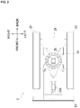
- the second battery unit 24 is located in the rear of the revolving bearing 41 and between the left-and right pair of crawlers 21, 21.
- the second battery unit 24 is fixed to a center frame 25 located at the center of the lower traveling body 2 and a left-and right pair of side frames 26, 26 located on the sides of the center frame 25.
- the power supply system 6 includes the power supplier 45 which converts an AC power supply voltage of the commercial power supply 5 into a DC power supply voltage, and the first battery unit 44 and the second battery unit 24 that charge or discharge the electric power from the power supplier 45.
- the power supply system 6 further includes a first electric path 6a disposed on the upper revolving body 4 and leads from the first battery unit 44 to the motor 43, a second electric path 6b disposed on the lower traveling body 2 and leads from the second battery unit 24, a connection electric path 6c connecting the first electric path 6a and the second electric path 6b, a converter 61 (corresponding to a voltage converting device) located on the connection electric path 6c, and a first inverter 62 and a second inverter 63 that convert the DC power supply voltage into the AC power supply voltage.
- the connection electric path 6c connects with the first electric path 6a at a first connection point 6d, and connects with the second electric path 6b at a second connection point 6e.
- the power supplier 45 converts the AC voltage supplied from the commercial power supply 5 via the feeder cable 51 into the DC voltage.
- a third electric path 6f leading from the power supplier 45 connects with the connection electric path 6c at a third connection point 6g.
- a feed relay 64 is located between the power supplier 45 and the third connection point 6g.
- the DC voltage of the power supplier 45 is supplied to the first battery unit 44 via the feed relay 64 and the first battery relay 65, so that the first battery unit 44 is charged.
- the DC voltage of the power supplier 45 is supplied to the second battery unit 24 via the feed relay 64, a connection relay 66, the converter 61, and a second battery relay 67, so that the second battery unit 24 is charged.
- the DC voltage of the power supplier 45 may be supplied to the first inverter 62 via the feed relay 64 and a first inverter relay 68.
- the first battery unit 44 supplies the DC voltage to the first inverter 62 via a first battery relay 65 and the first inverter relay 68.
- the first battery relay 65 is located between the first battery unit 44 and the first connection point 6d.
- the first inverter relay 68 is located between the first inverter 62 and the first connection point 6d.
- the first battery unit 44 can supply the DC voltage to the second electric path 6b via the connection electric path 6c.
- the second battery unit 24 supplies the DC voltage to the second inverter 63 via the second battery relay 67 and a second inverter relay 69.
- the second battery relay 67 is located between the second battery unit 24 and the second connection point 6e.
- the second inverter relay 69 is located between the second inverter 63 and the second connection point 6e.
- the second battery unit 24 can supply the DC voltage to the first electric path 6a via the connection electric path 6c.
- the first battery unit 44 and the second battery unit 24 store one or more batteries, the battery capacity is appropriately determined depending on a number of batteries stored therein.
- Examples of the battery include a lithium ion battery.
- the first inverter 62 converts the DC voltage supplied from the first battery unit 44 and/or the second battery unit 24 into the AC voltage.
- the AC voltage is supplied to the motor 43.
- the motor 43 causes a hydraulic pump 46 to work.
- FIG. 3 shows only the hydraulic pump 46, a plurality of hydraulic pumps may be provided.
- the hydraulic pump 46 supplies pressure oil to each hydraulic actuator 48 (i.e., the boom cylinder 31a, the arm cylinder 32a, the bucket cylinder 33a, the revolving motor, etc.) via a control valve 47.
- the second inverter 63 converts the DC voltage supplied from the second battery unit 24 and/or the first battery unit 44 into the AC voltage.
- the AC voltage is supplied to the traveling electric motor 22.
- the converter 61 is a DC-DC converter to convert a voltage with a direct current.
- the converter 61 is located on the connection electric path 6c and controls a voltage value such that current passing through the converter 61 is less than a set threshold.
- the converter 61 can control a voltage ratio between the first electric path 6a and the second electric path 6b based on a set value.
- a setting of voltages of the first electric path 6a and the second electric path 6b is not conducted by setting those voltages to an identical voltage by matching the number of the batteries connected in series composing the first battery unit 44 and that of the second battery unit 24, but conducted by setting the voltage ratio between the first electric path 6a and the second electric path 6b by means of the converter 61, whereby a maximum possible number of batteries of the first battery unit 44 and the second battery unit 24 can be mounted on the first battery unit 44 and the second battery unit 24, respectively.
- a slip ring 7 is arranged on the connection electric path 6c.
- the slip ring 7 is positioned inside a connecting portion between the lower traveling body 2 and the upper revolving body 4, specifically inside the revolving bearing 41. Furthermore, the slip ring 7 is located between the converter 61 and the second connection point 6e. No large current flows in the slip ring 7 connecting the first electric path 6a and the second electric path 6b because the first electric path 6a and the second electric path 6b are connected via the converter 61, whereby the increase of costs can be suppressed because a special type of slip ring is not necessary.
- the hydraulic shovel 1 which includes the lower traveling body 2 and the upper revolving body 4 revolvably mounted on the lower traveling body 2, is provided with: the motor 43 disposed on the upper revolving body 4 for driving the hydraulic shovel 1; the first battery unit 44 disposed on the upper revolving body 4; the second battery unit 24 disposed on the lower traveling body 2; and the power supplier 45 for externally supplying electric power to the first battery unit 44 and the second battery unit 24.
- the first electric path 6a disposed on the upper revolving body 4 and leading from the first battery unit 44 to the motor 43, the second electric path 6b disposed on the lower traveling body 2 and leading from the second battery unit 24, the connection electric path 6c for connecting the first electric path 6a and the second electric path 6b, and the converter 61 located on the connection electric path 6c are provided, and the converter 61 controls a voltage value such that the current passing through the converter 61 is less than the set threshold.
- the converter 61 controls the voltage ratio between the first electric path 6a and the second electric path 6b based on the set value.
- a setting of voltages of the first electric path 6a and the second electric path 6b is not conducted by setting those voltages to an identical voltage by matching the number of the batteries connected in series composing the first battery unit 44 and that of the second battery unit 24, but conducted by setting the voltage ratio between the first electric path 6a and the second electric path 6b by means of the converter 61, whereby a maximum possible number of batteries of the first battery unit 44 and the second battery unit 24 can be mounted on the first battery unit 44 and the second battery unit 24, respectively.
- the traveling electric motor 22 disposed on the lower traveling body 2 and connected to the second electric path 6b is provided.
- a power supply circuit of the upper revolving body 4 and that of the lower traveling body 2 can be operated independently, and thus even if the power supply circuit of the upper revolving body 4 is damaged, the hydraulic shovel 1 can be moved by means of only the power supply circuit of the lower traveling body 2.
- the first battery unit 44 can cover only an electric power which the second battery unit 24 cannot cover among the power consumed by the traveling electric motor 22 of the lower traveling body 2, a current flowing from the first electric path 6a to the second electric path 6b can be lower, and thus the parts procurement costs can be reduced because the general-purpose parts are available.
- the slip ring 7 arranged on the connection electric path 6c is provided, and the slip ring 7 is positioned inside the connecting portion between the lower traveling body 2 and the upper revolving body 4. No large current flows in the slip ring 7 connecting the first electric path 6a and the second electric path 6b because the first electric path 6a and the second electric path 6b are connected via the converter 61, whereby the increase of costs can be suppressed because a special type of slip ring is not necessary.
- the left-and-right crawlers 21, 21 are driven by the left-and-right traveling electric motors 22, 22, respectively, but the left-and-right crawlers 21, 21 may be driven by the left-and right traveling hydraulic motors 27, 27, respectively.
- the hydraulic pump 46 supplies the pressure oil to the traveling hydraulic motor 27.
- a swivel joint 28 is provided in the middle of an oil path 27a connecting the control valve 47 and a traveling hydraulic motor 27.
- the swivel joint 28 is located between the lower traveling body 2 and the upper revolving body 4.
- the hydraulic actuators (the boom cylinder 31a, the arm cylinder 32a, and the bucket cylinder 33a) to which the pressure oil is supplied by means of the hydraulic pump 46 driven by the motor 43 cause working parts (the boom 31, the arm 32, and the bucket 33) to work, but the entire working parts may be motorized by providing a plurality of electric motors.
- the blade 23 and the revolving motor, and the like can also be motorized.
- the power supplier 45 may be disposed on the lower traveling body 2.
- the power supply port to which the feeder cable 51 is connected is also provided on the lower traveling body 2.
Landscapes
- Engineering & Computer Science (AREA)
- Power Engineering (AREA)
- Mechanical Engineering (AREA)
- Transportation (AREA)
- Mining & Mineral Resources (AREA)
- Civil Engineering (AREA)
- General Engineering & Computer Science (AREA)
- Structural Engineering (AREA)
- Life Sciences & Earth Sciences (AREA)
- Sustainable Development (AREA)
- Sustainable Energy (AREA)
- Chemical & Material Sciences (AREA)
- Combustion & Propulsion (AREA)
- Operation Control Of Excavators (AREA)
- Arrangement Or Mounting Of Propulsion Units For Vehicles (AREA)
- Electric Propulsion And Braking For Vehicles (AREA)
Abstract
Description
- The present invention relates to an electrically powered construction machine.
- The following patent Literature 1 discloses an electrically powered work vehicle in which a revolving body is revolvably located on a traveling device and a battery is located at the rear of the revolving body. The following
patent Literature 2 discloses a battery-driven construction machine in which a battery unit is attached in a lower space between a pair of crawlers of a lower traveling body. -
- Patent Literature 1:
Japanese Patent Unexamined Publication No. 2013-139676 - Patent Literature 2:
Japanese Patent Unexamined Publication No. 2005-289181 - In the electrically powered work vehicle of the Patent Literature 1, when desiring to increase a battery capacity, it is necessary to stack batteries in the upper direction. There is, however, a problem of a lack of stability due to stacking batteries leading to a raised position of the center of gravity.
- Furthermore, in the battery-driven construction machine of
Patent Literature 2, by locating a battery unit on a lower traveling body, the position of the center of gravity as a whole can be lowered and thus the attitude can be stabilized. However, the battery capacity, which is increasable, is limited because the battery unit is located in the lower space between a pair of crawlers. - Therefore, in light of the above described problems, it is an object of the present invention to provide an electrically powered construction machine capable of improving the stability of the machine while increasing the battery capacity.
- The electrically powered construction machine according to the present invention, which includes a lower traveling body and an upper revolving body revolvably mounted on the lower traveling body, is provided with: an electric motor disposed on the upper revolving body for driving the electrically powered construction machine; a first electrical storage device disposed on the upper revolving body; a second electrical storage device disposed on the lower traveling body; and a feeder device for externally supplying electric power to the first electrical storage device and the second electrical storage device.
- According to the present invention, by mounting a power storage on the lower traveling body and the upper revolving body separately, it is possible to improve the stability of the machine while increasing the battery capacity.
-
-
FIG. 1 is a side view illustrating the electrically powered construction machine according to the present embodiment. -
FIG. 2 is a plan view of the lower traveling body. -
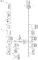
FIG. 3 is a block diagram of a power supply system to be mounted on the electrically powered construction machine. -
FIG. 4 is a block diagram of the power supply system according to an alternative embodiment. - Now, embodiments of the present invention will be described below with reference to the drawings.
- [Configuration of Electrically Powered Construction Machine] First of all, with reference to
FIG. 1 , a schematic structure of a hydraulic shovel 1 as an example of the electrically powered construction machine will be described. However, the electrically powered construction machine is not limited to the hydraulic shovel 1, and may be another vehicle such as a wheel loader, and the like. The hydraulic shovel 1 includes alower traveling body 2, a working machine 3, and an upper revolvingbody 4. - The lower traveling
body 2 includes a left-and-right pair ofcrawlers electric motors electric motors right crawlers body 2 is provided with ablade 23 and ablade cylinder 23a which is a hydraulic cylinder for rotating theblade 23 in the vertical direction. - The working machine 3 includes a
boom 31, anarm 32, and abucket 33, and is capable of an excavation work of earth and sand by driving these independently. Theboom 31, thearm 32, and thebucket 33 correspond to working parts, respectively, and the hydraulic shovel 1 includes a plurality of working parts. - The
boom 31 is revolved by aboom cylinder 31a whose base end portion is supported by a front portion of the upper revolvingbody 4 and which is movable freely in an expanded or a contracted way. Furthermore, thearm 32 is revolved by anarm cylinder 32a whose base end portion is supported by a tip portion of theboom 31 and which is movable freely in an expanded and a contracted way. Moreover, thebucket 33 is revolved by abucket cylinder 33a whose base end portion is supported by a tip portion of thearm 32 and which is movable freely in an expanded or a contracted way. Each of theboom cylinder 31a, thearm cylinder 32a, and thebucket cylinder 33a is composed of a hydraulic cylinder. - The upper revolving
body 4 is configured to be revolvable with respect to the lower travelingbody 2 via a revolving bearing 41. There are arranged on the upper revolving body 4 asteering portion 42, a revolving motor (not shown), a motor 43 (corresponding to an electric motor), a first battery unit 44 (corresponding to a first electrical storage device), and a power supplier 45 (corresponding to a feeder device). The upper revolvingbody 4 revolves via the revolving bearing 41 by means of a driving force of the revolving motor. In addition, there are arranged on the upper revolving body 4 a plurality of hydraulic pumps (not shown inFIG. 1 ) driven by themotor 43. These hydraulic pumps supply pressure oil to each hydraulic actuator (i.e., theblade cylinder 23a, theboom cylinder 31a, thearm cylinder 32a, and thebucket cylinder 33a, the revolving motor, etc.). Besides, thepower supplier 45 may be disposed on the lowertraveling body 2. - A driver's
seat 421 is positioned in thesteering potion 42. A pair of work operation levers 422, 422 are arranged on the left and right sides of the driver'sseat 421, as well as a pair oftraveling levers seat 421. An operator can control each hydraulic actuator with sitting on the driver'sseat 421 by operating the work operation levers 422, 422, the traveling levers 423, 423, etc. to perform traveling, revolving, working, and the like. - The upper revolving
body 4 is provided with a power supply port (not shown), and by connecting afeeder cable 51 of a commercial power supply 5 (corresponding to an external power supply) to the power supply port, thecommercial power supply 5 can be connected to thepower supplier 45. - A second battery unit 24 (corresponding to a second electrical storage device) is disposed on the
lower traveling body 2. Thesecond battery unit 24 is located in the rear of the revolving bearing 41 and between the left-and right pair ofcrawlers second battery unit 24 is fixed to acenter frame 25 located at the center of the lowertraveling body 2 and a left-and right pair ofside frames center frame 25. - With reference to
FIG. 3 , apower supply system 6, which is mounted on the hydraulic shovel 1 and supplies electric power to themotor 43 and the travelingelectric motor 22, will be described below. Thepower supply system 6 includes thepower supplier 45 which converts an AC power supply voltage of thecommercial power supply 5 into a DC power supply voltage, and thefirst battery unit 44 and thesecond battery unit 24 that charge or discharge the electric power from thepower supplier 45. - The
power supply system 6 further includes a firstelectric path 6a disposed on the upper revolvingbody 4 and leads from thefirst battery unit 44 to themotor 43, a secondelectric path 6b disposed on thelower traveling body 2 and leads from thesecond battery unit 24, a connectionelectric path 6c connecting the firstelectric path 6a and the secondelectric path 6b, a converter 61 (corresponding to a voltage converting device) located on the connectionelectric path 6c, and afirst inverter 62 and asecond inverter 63 that convert the DC power supply voltage into the AC power supply voltage. The connectionelectric path 6c connects with the firstelectric path 6a at afirst connection point 6d, and connects with the secondelectric path 6b at asecond connection point 6e. - The
power supplier 45 converts the AC voltage supplied from thecommercial power supply 5 via thefeeder cable 51 into the DC voltage. A thirdelectric path 6f leading from thepower supplier 45 connects with the connectionelectric path 6c at athird connection point 6g. Afeed relay 64 is located between thepower supplier 45 and thethird connection point 6g. The DC voltage of thepower supplier 45 is supplied to thefirst battery unit 44 via thefeed relay 64 and thefirst battery relay 65, so that thefirst battery unit 44 is charged. Furthermore, the DC voltage of thepower supplier 45 is supplied to thesecond battery unit 24 via thefeed relay 64, aconnection relay 66, theconverter 61, and asecond battery relay 67, so that thesecond battery unit 24 is charged. Moreover, the DC voltage of thepower supplier 45 may be supplied to thefirst inverter 62 via thefeed relay 64 and afirst inverter relay 68. - The
first battery unit 44 supplies the DC voltage to thefirst inverter 62 via afirst battery relay 65 and thefirst inverter relay 68. Thefirst battery relay 65 is located between thefirst battery unit 44 and thefirst connection point 6d. Furthermore, thefirst inverter relay 68 is located between thefirst inverter 62 and thefirst connection point 6d. Moreover, thefirst battery unit 44 can supply the DC voltage to the secondelectric path 6b via the connectionelectric path 6c. - The
second battery unit 24 supplies the DC voltage to thesecond inverter 63 via thesecond battery relay 67 and asecond inverter relay 69. Thesecond battery relay 67 is located between thesecond battery unit 24 and thesecond connection point 6e. Furthermore, thesecond inverter relay 69 is located between thesecond inverter 63 and thesecond connection point 6e. Moreover, thesecond battery unit 24 can supply the DC voltage to the firstelectric path 6a via the connectionelectric path 6c. - The
first battery unit 44 and thesecond battery unit 24 store one or more batteries, the battery capacity is appropriately determined depending on a number of batteries stored therein. Examples of the battery include a lithium ion battery. - The
first inverter 62 converts the DC voltage supplied from thefirst battery unit 44 and/or thesecond battery unit 24 into the AC voltage. The AC voltage is supplied to themotor 43. Themotor 43 causes ahydraulic pump 46 to work. Besides, althoughFIG. 3 shows only thehydraulic pump 46, a plurality of hydraulic pumps may be provided. Thehydraulic pump 46 supplies pressure oil to each hydraulic actuator 48 (i.e., theboom cylinder 31a, thearm cylinder 32a, thebucket cylinder 33a, the revolving motor, etc.) via acontrol valve 47. - The
second inverter 63 converts the DC voltage supplied from thesecond battery unit 24 and/or thefirst battery unit 44 into the AC voltage. The AC voltage is supplied to the travelingelectric motor 22. - The
converter 61 is a DC-DC converter to convert a voltage with a direct current. Theconverter 61 is located on the connectionelectric path 6c and controls a voltage value such that current passing through theconverter 61 is less than a set threshold. By connecting the firstelectric path 6a and the secondelectric path 6b via theconverter 61, even if a power consumption balance between thefirst battery unit 44 and thesecond battery unit 24 is significantly different, no large current flows in a circuit, and thus the circuit would never be damaged as well as parts procurement costs can be reduced because general-purpose parts are available. - Furthermore, the
converter 61 can control a voltage ratio between the firstelectric path 6a and the secondelectric path 6b based on a set value. A setting of voltages of the firstelectric path 6a and the secondelectric path 6b is not conducted by setting those voltages to an identical voltage by matching the number of the batteries connected in series composing thefirst battery unit 44 and that of thesecond battery unit 24, but conducted by setting the voltage ratio between the firstelectric path 6a and the secondelectric path 6b by means of theconverter 61, whereby a maximum possible number of batteries of thefirst battery unit 44 and thesecond battery unit 24 can be mounted on thefirst battery unit 44 and thesecond battery unit 24, respectively. - A
slip ring 7 is arranged on the connectionelectric path 6c. Theslip ring 7 is positioned inside a connecting portion between thelower traveling body 2 and the upper revolvingbody 4, specifically inside the revolvingbearing 41. Furthermore, theslip ring 7 is located between theconverter 61 and thesecond connection point 6e. No large current flows in theslip ring 7 connecting the firstelectric path 6a and the secondelectric path 6b because the firstelectric path 6a and the secondelectric path 6b are connected via theconverter 61, whereby the increase of costs can be suppressed because a special type of slip ring is not necessary. - As described above, the hydraulic shovel 1 according to the present embodiment, which includes the
lower traveling body 2 and the upper revolvingbody 4 revolvably mounted on thelower traveling body 2, is provided with: themotor 43 disposed on the upper revolvingbody 4 for driving the hydraulic shovel 1; thefirst battery unit 44 disposed on the upper revolvingbody 4; thesecond battery unit 24 disposed on thelower traveling body 2; and thepower supplier 45 for externally supplying electric power to thefirst battery unit 44 and thesecond battery unit 24. - By mounting the batteries on the
lower traveling body 2 and the upper revolvingbody 4 separately, it is possible to increase the stability of the machine while increasing the capacity of the battery. - In the present embodiment, the first
electric path 6a disposed on the upper revolvingbody 4 and leading from thefirst battery unit 44 to themotor 43, the secondelectric path 6b disposed on thelower traveling body 2 and leading from thesecond battery unit 24, the connectionelectric path 6c for connecting the firstelectric path 6a and the secondelectric path 6b, and theconverter 61 located on the connectionelectric path 6c are provided, and theconverter 61 controls a voltage value such that the current passing through theconverter 61 is less than the set threshold. By connecting the firstelectric path 6a and the secondelectric path 6b via theconverter 61, even if a power consumption balance between thefirst battery unit 44 and thesecond battery unit 24 is significantly different, no large current flows in a circuit, and thus the circuit would never be damaged as well as parts procurement costs can be reduced because general-purpose parts are available. - In the present embodiment, the
converter 61 controls the voltage ratio between the firstelectric path 6a and the secondelectric path 6b based on the set value. A setting of voltages of the firstelectric path 6a and the secondelectric path 6b is not conducted by setting those voltages to an identical voltage by matching the number of the batteries connected in series composing thefirst battery unit 44 and that of thesecond battery unit 24, but conducted by setting the voltage ratio between the firstelectric path 6a and the secondelectric path 6b by means of theconverter 61, whereby a maximum possible number of batteries of thefirst battery unit 44 and thesecond battery unit 24 can be mounted on thefirst battery unit 44 and thesecond battery unit 24, respectively. - In the present embodiment, the traveling
electric motor 22 disposed on thelower traveling body 2 and connected to the secondelectric path 6b is provided. Thereby, a power supply circuit of the upper revolvingbody 4 and that of thelower traveling body 2 can be operated independently, and thus even if the power supply circuit of the upper revolvingbody 4 is damaged, the hydraulic shovel 1 can be moved by means of only the power supply circuit of thelower traveling body 2. Furthermore, as thefirst battery unit 44 can cover only an electric power which thesecond battery unit 24 cannot cover among the power consumed by the travelingelectric motor 22 of thelower traveling body 2, a current flowing from the firstelectric path 6a to the secondelectric path 6b can be lower, and thus the parts procurement costs can be reduced because the general-purpose parts are available. - In the present embodiment, the
slip ring 7 arranged on the connectionelectric path 6c is provided, and theslip ring 7 is positioned inside the connecting portion between thelower traveling body 2 and the upper revolvingbody 4. No large current flows in theslip ring 7 connecting the firstelectric path 6a and the secondelectric path 6b because the firstelectric path 6a and the secondelectric path 6b are connected via theconverter 61, whereby the increase of costs can be suppressed because a special type of slip ring is not necessary. - In the above described embodiment, the left-and-
right crawlers electric motors right crawlers hydraulic motors hydraulic pump 46 supplies the pressure oil to the travelinghydraulic motor 27. In such a case, a swivel joint 28 is provided in the middle of anoil path 27a connecting thecontrol valve 47 and a travelinghydraulic motor 27. The swivel joint 28 is located between thelower traveling body 2 and the upper revolvingbody 4. - In the above described embodiment, the hydraulic actuators (the
boom cylinder 31a, thearm cylinder 32a, and thebucket cylinder 33a) to which the pressure oil is supplied by means of thehydraulic pump 46 driven by themotor 43 cause working parts (theboom 31, thearm 32, and the bucket 33) to work, but the entire working parts may be motorized by providing a plurality of electric motors. In addition, theblade 23 and the revolving motor, and the like can also be motorized. - In the above described embodiment, although the
power supplier 45 is disposed on the upper revolvingbody 4, thepower supplier 45 may be disposed on thelower traveling body 2. In such a case, the power supply port to which thefeeder cable 51 is connected is also provided on thelower traveling body 2. By disposing thepower supplier 45 on thelower traveling body 2, it is possible to prevent the upper revolvingbody 4 from catching and tangling up thefeeder cable 51 when it is revolving. On the other hand, by disposing thepower supplier 45 on the upper revolvingbody 4, it is possible to prevent thecrawler 21 from trampling thefeeder cable 51. - Although the embodiments according to the present invention have been described with reference to the drawings, it should be considered that a specific configuration is not limited to the embodiments. The scope of the invention is clearly shown by the claims as well as the description of the embodiments described above, and encompass any modifications or changes within the meaning and range equivalent to the claims.
-
- 1
- Hydraulic shovel
- 2
- Lower traveling body
- 4
- Upper revolving body
- 5
- Commercial power supply
- 6a
- First electric path
- 6b
- Second electric path
- 6c
- Connection electric path
- 7
- Slip ring
- 22
- Traveling electric motor
- 24
- Second battery unit
- 41
- Revolving bearing
- 43
- Motor
- 44
- First battery unit
- 45
- Power supplier
Claims (5)
- An electrically powered construction machine which includes a lower traveling body and an upper revolving body revolvably mounted on the lower traveling body, comprising:an electric motor disposed on the upper revolving body for driving the electrically powered construction machine;a first electrical storage device disposed on the upper revolving body;a second electrical storage device disposed on the lower traveling body; anda feeder device for externally supplying electric power to the first electrical storage device and the second electrical storage device.
- The electrically powered construction machine according to claim 1 further comprising:a first electric path disposed on the upper revolving body and leading from the first electrical storage device to the electric motor;a second electric path disposed on the lower traveling body and leading from the second electrical storage device;a connection electric path for connecting the first electric path and the second electric path; anda voltage converting device located on the connection electric path,wherein the voltage converting device controls a voltage value such that current passing through the voltage converting device is less than a set threshold.
- The electrically powered construction machine according to claim 2, wherein the voltage converting device controls a voltage ratio between the first electric path and the second electric path based on a set value.
- The electrically powered construction machine according to claim 2 or 3 further comprising a traveling electrically powered motor disposed on the lower traveling body and connected to the second electric path.
- The electrically powered construction machine according to any one of claims 2 to 4 further comprising a slip ring arranged on the connection electric path, wherein the slip ring is positioned inside a connecting portion between the lower traveling body and the upper revolving body.
Applications Claiming Priority (2)
| Application Number | Priority Date | Filing Date | Title |
|---|---|---|---|
| JP2018237019A JP7063796B2 (en) | 2018-12-19 | 2018-12-19 | Electric construction machinery |
| PCT/JP2019/045415 WO2020129524A1 (en) | 2018-12-19 | 2019-11-20 | Electrically powered construction machine |
Publications (2)
| Publication Number | Publication Date |
|---|---|
| EP3901380A1 true EP3901380A1 (en) | 2021-10-27 |
| EP3901380A4 EP3901380A4 (en) | 2022-09-28 |
Family
ID=71101268
Family Applications (1)
| Application Number | Title | Priority Date | Filing Date |
|---|---|---|---|
| EP19900696.6A Pending EP3901380A4 (en) | 2018-12-19 | 2019-11-20 | ELECTRICALLY POWERED CONSTRUCTION MACHINE |
Country Status (6)
| Country | Link |
|---|---|
| US (1) | US12291836B2 (en) |
| EP (1) | EP3901380A4 (en) |
| JP (1) | JP7063796B2 (en) |
| KR (1) | KR102938076B1 (en) |
| CN (1) | CN113242922A (en) |
| WO (1) | WO2020129524A1 (en) |
Cited By (2)
| Publication number | Priority date | Publication date | Assignee | Title |
|---|---|---|---|---|
| CN112004973A (en) * | 2018-04-24 | 2020-11-27 | 洋马动力科技有限公司 | Electric working machine |
| EP4524327A1 (en) * | 2023-09-11 | 2025-03-19 | Advanced Robotic Engineering Sp. z o.o. | Drive system for multi-purpose machines |
Families Citing this family (13)
| Publication number | Priority date | Publication date | Assignee | Title |
|---|---|---|---|---|
| JP7502458B2 (en) * | 2020-10-30 | 2024-06-18 | 本田技研工業株式会社 | Work vehicle |
| JP7389064B2 (en) * | 2021-01-14 | 2023-11-29 | ヤンマーホールディングス株式会社 | construction machinery |
| EP4183925A1 (en) | 2021-11-18 | 2023-05-24 | Joseph Vögele AG | Heating system for a construction machine |
| DE202022105314U1 (en) * | 2022-09-21 | 2024-01-03 | Liebherr-Werk Nenzing Gmbh | Working machine with electric drive |
| DE202022105317U1 (en) * | 2022-09-21 | 2024-01-02 | Liebherr-Werk Nenzing Gmbh | Working machine with electric drive |
| JP7431916B1 (en) | 2022-09-29 | 2024-02-15 | 日立建機株式会社 | construction machinery |
| WO2024085516A1 (en) * | 2022-10-17 | 2024-04-25 | 에이치디현대인프라코어 주식회사 | Electric excavator |
| KR20250061755A (en) * | 2022-10-17 | 2025-05-08 | 에이치디현대인프라코어 주식회사 | Electric excavator |
| KR102706748B1 (en) * | 2022-12-07 | 2024-09-19 | 드라이브텍 주식회사 | Battery management system for stable operation of robots attached to the electric vehicle |
| FR3149625B1 (en) * | 2023-06-08 | 2025-06-13 | Poclain Hydraulics Ind | Improved electrohydraulic excavator architecture |
| FR3157879B1 (en) * | 2023-12-29 | 2026-02-06 | Vincent Robin | Electric excavator with a freely rotating turret adapted for autonomously installing/removing a set of batteries; methods for autonomously installing and removing a set of batteries from an electric excavator |
| WO2025216968A1 (en) * | 2024-04-07 | 2025-10-16 | Doosan Bobcat North America Inc. | Electric drive motor and inverter on a power machine |
| EP4708604A1 (en) * | 2024-09-06 | 2026-03-11 | BAUER Maschinen GmbH | Electrically operated civil engineering machine and method for electrically operating a civil engineering machine |
Family Cites Families (15)
| Publication number | Priority date | Publication date | Assignee | Title |
|---|---|---|---|---|
| DE3101042C2 (en) * | 1981-01-15 | 1984-11-15 | Jastram-Werke GmbH & Co KG, 2050 Hamburg | Oars for watercraft |
| JP3838679B2 (en) | 1995-08-10 | 2006-10-25 | 富士通株式会社 | Interactive delay analysis system for electronic circuits |
| JP3828679B2 (en) * | 1999-06-28 | 2006-10-04 | 株式会社神戸製鋼所 | Hybrid construction machinery |
| JP2005289181A (en) | 2004-03-31 | 2005-10-20 | Sumitomo (Shi) Construction Machinery Manufacturing Co Ltd | Battery mounting structure of battery-driven type shovel, and battery unit used for the battery-driven type shovel |
| JP4434123B2 (en) | 2005-10-12 | 2010-03-17 | コベルコ建機株式会社 | Hybrid construction machine |
| JP5096012B2 (en) | 2007-02-07 | 2012-12-12 | 株式会社竹内製作所 | Electric drive work vehicle |
| KR100830135B1 (en) | 2008-02-12 | 2008-05-20 | 에스씨종합건설(주) | Battery Charging System for Electric Excavators |
| JP5401251B2 (en) * | 2009-10-07 | 2014-01-29 | 日立建機株式会社 | Construction machinery |
| JP2011103720A (en) * | 2009-11-10 | 2011-05-26 | Takeuchi Seisakusho:Kk | Power supply system for hydraulic unit |
| US20140027432A1 (en) * | 2010-04-01 | 2014-01-30 | Dana A. Hennessy | Thawing System for Machinery Undercarriages |
| JP5459408B2 (en) * | 2010-10-21 | 2014-04-02 | トヨタ自動車株式会社 | Power supply system for electric vehicle, control method therefor, and electric vehicle |
| US9349532B2 (en) * | 2010-11-25 | 2016-05-24 | Volvo Construction Equipment Ab | Turning joint for electric excavator |
| KR101737636B1 (en) * | 2010-12-24 | 2017-05-18 | 두산인프라코어 주식회사 | Swing control apparatus for hybrid construction machnery |
| JP2013139676A (en) | 2011-12-28 | 2013-07-18 | Yanmar Co Ltd | Electric work vehicle |
| JP6420120B2 (en) * | 2014-10-27 | 2018-11-07 | 日立建機株式会社 | Construction machinery management station terminal system |
-
2018
- 2018-12-19 JP JP2018237019A patent/JP7063796B2/en active Active
-
2019
- 2019-11-20 CN CN201980082517.0A patent/CN113242922A/en active Pending
- 2019-11-20 US US17/416,458 patent/US12291836B2/en active Active
- 2019-11-20 WO PCT/JP2019/045415 patent/WO2020129524A1/en not_active Ceased
- 2019-11-20 KR KR1020217008690A patent/KR102938076B1/en active Active
- 2019-11-20 EP EP19900696.6A patent/EP3901380A4/en active Pending
Cited By (3)
| Publication number | Priority date | Publication date | Assignee | Title |
|---|---|---|---|---|
| CN112004973A (en) * | 2018-04-24 | 2020-11-27 | 洋马动力科技有限公司 | Electric working machine |
| EP3786371A4 (en) * | 2018-04-24 | 2022-01-26 | Yanmar Power Technology Co., Ltd. | ELECTRIC CONSTRUCTION MACHINERY |
| EP4524327A1 (en) * | 2023-09-11 | 2025-03-19 | Advanced Robotic Engineering Sp. z o.o. | Drive system for multi-purpose machines |
Also Published As
| Publication number | Publication date |
|---|---|
| EP3901380A4 (en) | 2022-09-28 |
| WO2020129524A1 (en) | 2020-06-25 |
| US20220074163A1 (en) | 2022-03-10 |
| JP2020097867A (en) | 2020-06-25 |
| KR20210104017A (en) | 2021-08-24 |
| US12291836B2 (en) | 2025-05-06 |
| JP7063796B2 (en) | 2022-05-09 |
| CN113242922A (en) | 2021-08-10 |
| KR102938076B1 (en) | 2026-03-11 |
Similar Documents
| Publication | Publication Date | Title |
|---|---|---|
| US12291836B2 (en) | Electrically powered construction machine | |
| US12252864B2 (en) | Working machine, a work attachment and a combination thereof | |
| CN112004973A (en) | Electric working machine | |
| CN102459769B (en) | Hybrid excavator and its control method | |
| JP4979529B2 (en) | Battery powered construction machinery | |
| WO2022153735A1 (en) | Construction machine | |
| US10364549B2 (en) | Hybrid construction machine | |
| JP6073169B2 (en) | Excavator | |
| JP5015073B2 (en) | Charging system | |
| WO2011058699A1 (en) | Power supply system | |
| JP2007284874A (en) | Construction machinery | |
| JP2011103720A (en) | Power supply system for hydraulic unit | |
| JP2008297031A (en) | Industrial vehicle | |
| CN102906344A (en) | Control device for hybrid construction machine | |
| US12528368B2 (en) | Electric work machine | |
| EP4331889A1 (en) | Charging system for an electric work vehicle and associated method | |
| KR101507952B1 (en) | Electric excavator system | |
| JP2013163946A (en) | Construction machine | |
| JP5411023B2 (en) | Charging system | |
| US12606988B2 (en) | Hot swappable battery configuration | |
| EP4606957A1 (en) | Electric excavator | |
| KR20250141202A (en) | Power systems for work machines and electric work machines | |
| JP2013035614A (en) | Work vehicle | |
| KR20120110371A (en) | Electric excavator system |
Legal Events
| Date | Code | Title | Description |
|---|---|---|---|
| STAA | Information on the status of an ep patent application or granted ep patent |
Free format text: STATUS: THE INTERNATIONAL PUBLICATION HAS BEEN MADE |
|
| PUAI | Public reference made under article 153(3) epc to a published international application that has entered the european phase |
Free format text: ORIGINAL CODE: 0009012 |
|
| STAA | Information on the status of an ep patent application or granted ep patent |
Free format text: STATUS: REQUEST FOR EXAMINATION WAS MADE |
|
| 17P | Request for examination filed |
Effective date: 20210705 |
|
| AK | Designated contracting states |
Kind code of ref document: A1 Designated state(s): AL AT BE BG CH CY CZ DE DK EE ES FI FR GB GR HR HU IE IS IT LI LT LU LV MC MK MT NL NO PL PT RO RS SE SI SK SM TR |
|
| DAV | Request for validation of the european patent (deleted) | ||
| DAX | Request for extension of the european patent (deleted) | ||
| A4 | Supplementary search report drawn up and despatched |
Effective date: 20220831 |
|
| RIC1 | Information provided on ipc code assigned before grant |
Ipc: B60K 1/04 20190101ALI20220825BHEP Ipc: E02F 9/00 20060101AFI20220825BHEP |
|
| STAA | Information on the status of an ep patent application or granted ep patent |
Free format text: STATUS: EXAMINATION IS IN PROGRESS |
|
| 17Q | First examination report despatched |
Effective date: 20250123 |