EP3901349B1 - Device for controlling the movement of the needles of a needle loom, in particular an elliptic needle loom, and needle loom comprising such a device - Google Patents
Device for controlling the movement of the needles of a needle loom, in particular an elliptic needle loom, and needle loom comprising such a device Download PDFInfo
- Publication number
- EP3901349B1 EP3901349B1 EP21169008.6A EP21169008A EP3901349B1 EP 3901349 B1 EP3901349 B1 EP 3901349B1 EP 21169008 A EP21169008 A EP 21169008A EP 3901349 B1 EP3901349 B1 EP 3901349B1
- Authority
- EP
- European Patent Office
- Prior art keywords
- rod
- adjustment
- tie
- lever
- needles
- Prior art date
- Legal status (The legal status is an assumption and is not a legal conclusion. Google has not performed a legal analysis and makes no representation as to the accuracy of the status listed.)
- Active
Links
- 239000000835 fiber Substances 0.000 description 9
- 229940082150 encore Drugs 0.000 description 5
- 238000005461 lubrication Methods 0.000 description 5
- 230000001276 controlling effect Effects 0.000 description 4
- 238000007789 sealing Methods 0.000 description 4
- 230000002349 favourable effect Effects 0.000 description 2
- 230000000694 effects Effects 0.000 description 1
- 230000010355 oscillation Effects 0.000 description 1
- 230000010363 phase shift Effects 0.000 description 1
- 230000001105 regulatory effect Effects 0.000 description 1
- 238000000926 separation method Methods 0.000 description 1
Images


Classifications
-
- D—TEXTILES; PAPER
- D04—BRAIDING; LACE-MAKING; KNITTING; TRIMMINGS; NON-WOVEN FABRICS
- D04H—MAKING TEXTILE FABRICS, e.g. FROM FIBRES OR FILAMENTARY MATERIAL; FABRICS MADE BY SUCH PROCESSES OR APPARATUS, e.g. FELTS, NON-WOVEN FABRICS; COTTON-WOOL; WADDING ; NON-WOVEN FABRICS FROM STAPLE FIBRES, FILAMENTS OR YARNS, BONDED WITH AT LEAST ONE WEB-LIKE MATERIAL DURING THEIR CONSOLIDATION
- D04H18/00—Needling machines
- D04H18/02—Needling machines with needles
-
- D—TEXTILES; PAPER
- D06—TREATMENT OF TEXTILES OR THE LIKE; LAUNDERING; FLEXIBLE MATERIALS NOT OTHERWISE PROVIDED FOR
- D06H—MARKING, INSPECTING, SEAMING OR SEVERING TEXTILE MATERIALS
- D06H5/00—Seaming textile materials
Definitions
- the present invention relates to a device for controlling the movement along a trajectory of the needles of a needling machine, in particular the component along the direction MD of the movement along an elliptical trajectory of the needles of a needling machine with elliptical movement, as well as to a needling machine, in particular an elliptical, comprising a control device of this kind.
- an elliptical needling machine for consolidating by needling a veil or a layer of fibers, in particular of nonwoven, comprises at least one needle board, in front of which the veil or the layer of fibers passes while moving in a direction of feed or machine direction or MD, and drive means configured to give the at least one needle board and/or the needles a back and forth movement in the direction perpendicular or substantially perpendicular to the plane of the web or of the veil so that the needles cross in one direction, then in the other, the veil or the web of fibers, having an elliptical trajectory.
- a device according to the preamble of claim 1 is known.
- drive means MD configured to impart to the needles and/or the needle board the MD component of their elliptical movement.
- Known MD drive means are complex in structure and take up a lot of space. We would like to have available a driving device with a simpler structure, which in particular allows its adjustment both on and off. In addition, in some cases, it is desired to place these drive means MD in a sealed casing, alongside the means for driving the boards in the longitudinal direction, and to do this a more compact structure is sought.
- a device for controlling the component in a given direction, for example the direction MD, of the movement along a given trajectory, for example elliptical, of the needles of a needling machine, for example an elliptical needling machine, intended to consolidate by needling a veil or a layer of fibres, in particular of nonwoven comprising at least one needle board having a field of needles and drive means configured to impart to the at least one needle board and/or to the needles a back and forth movement so that the needles have a given trajectory, for example elliptical, to cross in one direction, then in the other, the veil or the web of fibers which moves in front of them in one direction machine or feed MD to consolidate it, the control device being as defined in claim 1.
- said one given direction is the MD direction and said one given trajectory is elliptical
- the drive means comprising MD drive means configured to impart to the at least one board and/or to the needles the MD component of their elliptical motion.
- said one given direction is the vertical direction and said one given trajectory is rectilinear. The movement of the hands being back and forth in the vertical direction.
- the present invention also relates to a needling machine, in particular an elliptical, comprising a control device according to the invention.
- the needling machine comprises one or more columns to which one or more respective needle boards are connected, in particular in a tilting manner, longitudinal drive means being provided to impart to the or each column a movement of moves back and forth in a direction parallel to the longitudinal axis of the column, at least part of the or each column and the longitudinal drive means being housed in a sealed casing, in which the control device MD is also housed in the sealed housing.
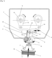
- FIG. 1 there is shown a first embodiment of a needling machine according to the invention.
- the housing is shown in a sectional view and the rest of the needling machine in a front view, part of the guide pot being cut away.
- This needling machine comprises a needle board 10 comprising needles 1 projecting from the underside of the board, being arranged either in rows and columns, or randomly or pseudo-randomly, as is well known in the field.
- the needle board 10 is carried by a beam 2, called the moving beam.
- the beam 2 and board 10 are integral with each other, but removably, to allow, when the needles are worn and/or broken, to easily replace a board with a new board.
- the needles are intended to have a back and forth movement with an elliptical trajectory from top to bottom and from bottom to top to cross in one direction, then in the other, a sheet or a veil of fibers which are made pass in front of them in a direction of lead or MD, namely from left to right in the horizontal direction to the figure.
- a longitudinal column 3 extending along a longitudinal axis 11 perpendicular to the plane of the board is secured to the movable beam 2, so that the movements of the column 3, of the movable beam 2, of the needle board 10 and of the hands are identical, namely with the same elliptical trajectory.
- Drive means are provided to impart to the column 3 (and therefore also to the needle board 10, to the movable beam 2 and to the needles 1) a movement having a component in a direction parallel to the longitudinal axis 11 and a component along the direction MD, so as to have an elliptical trajectory as shown in figure 1 by an ellipse for the hands.
- a sealed casing 7 encloses the drive means and part of the column 3, the latter passing through the wall of the casing 7 by passing through a guide pot 4, the interface of which with the casing 7 is sealed by means of a seal which according to one possible embodiment may take the form of a seal 50 with bellows.
- the guide pot 4 is mounted tilting with respect to an axis 5 fixed with respect to the housing 7, parallel to the direction CD (perpendicular to the direction MD and to the longitudinal axis 11).
- the column 3 can slide inside the guide pot 4.
- Guide rings 16 are arranged on the inner wall of the guide pot 4, to ensure sliding and lubrication between the column 3 and the guide pot 4. Sealing between column 3 and guide pot 4 is ensured by a gasket, not shown, attached to the base of the guide pot.
- the fixed axis 5 is positioned substantially at the level of the opening of the casing through which the guide pot 4 passes, in particular in the opening.
- the drive means comprise first longitudinal drive means configured to impart a reciprocating movement to the column in a direction parallel to the longitudinal axis.
- These first drive means consist of two systems 6 with eccentric shafts 12 and connecting rods 13 and an intermediate connecting rod 9.
- the shafts 12 drive the heads of the two connecting rods 13 by rotating (as represented by the two arrows at the top of the figure 1 ) in opposite directions.
- the feet 14 of the two connecting rods 13 are each articulated at one end of the intermediate connecting rod 9 which extends in the direction MD.
- the intermediate link 9 further comprises a lug 15 extending centrally downwards. The end of the leg 15 is hinged to the upper end of the column 3.
- These first longitudinal drive means make it possible to impart to the column 3 a movement only back and forth along the longitudinal axis.
- second transverse drive means in the form of a main rod 8 arranged in the direction MD.
- One end of the connecting rod 8 is mounted articulated to the guide pot 4, inside the casing 7, at a point 17 at a distance from the axis 5 of rotation of the pot, in particular substantially the upper end of the pot. It is thus imparted to the guide pot 4 a movement of oscillation back and forth which results on the column 3 which crosses it by a movement back and forth in the direction MD, or substantially in the direction MD (as represented by the double arrow above the link 8 at the figure 1 ).
- the other end of the link 8 is coupled to a control system, called the advance system, which is any one of those shown below in figure 5 , 6A , 6B And 7 .
- a mass 19 for balancing the system is coupled to the guide pot 4, being fixed to the latter on the side opposite that where the advance system is located.
- the advance system being housed in the sealed casing, it can be actuated either by an independent motor, or by one of the control shafts 6 of the first vertical drive means, or by a connecting rod mounted directly on an integral eccentric one of the control shafts 6 of the first drive means.
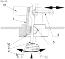
- FIG. 2 To the picture 2 , there is shown another embodiment of a needling machine according to the invention.
- the housing is shown in a sectional view and the rest of the needling machine in a front view, part of a guide pot being cut away.
- This needling machine comprises two needle boards 10' comprising needles 1' protruding from the underside of the board being arranged either in rows and columns, or randomly or pseudo-randomly, as is well known in the domain.
- Each needle board 10' is carried by a respective beam 2', called a moving beam.
- the needles are intended to have a back and forth movement with an elliptical trajectory from top to bottom and from bottom to top to cross in one direction, then in the other, a sheet or a veil of fibers which are made pass in front of it in a direction of lead or MD, namely from left to right in the horizontal direction to the figure.
- Two longitudinal columns 3' extend along longitudinal axes 11' perpendicular to the plane of the board.
- the columns 3' are each secured to a mobile beam 2', so that the movements of the column 3', of the beam 2 'mobile, the board 10' needles and needles are identical, namely with the same elliptical trajectory.
- Drive means are provided to impart to each column 3' (and therefore also to the boards 10' with needles, to the mobile beams 2' and to the needles 1) a movement having a component along a direction parallel to the longitudinal axis 11 'and a component in the direction MD, so as to have an elliptical trajectory as shown in figure 2 by an ellipse for the hands.
- a sealed casing 7' encloses the drive means and part of the columns 3', the latter passing through the wall of the casing 7' by passing through respective guide pots 4', the interfaces of which with the casing 7' are sealed by via seals (not shown, but which for example can be made in the form of bellows seals as shown in Figure 1A ).
- Each guide pot 4' is mounted tilting with respect to an axis 5', fixed with respect to the casing 7' and parallel to the direction CD (perpendicular to the direction MD and to the longitudinal axis 11').
- Each column 3' can slide inside the respective guide pot 4'.
- Guide rings 16' are arranged on the inner wall of each guide pot 4', to ensure sliding and lubrication between the column 3' and the respective guide pot 4'.
- the seal between the column 3' and the respective guide pot 4' is ensured by a seal, not shown, fixed to the base of the guide pot.
- the drive means comprise first longitudinal drive means configured to impart a reciprocating movement to each column in a direction parallel to the longitudinal axis.
- These first drive means consist of two systems 6' with eccentric shafts 12' and connecting rods 13'.
- the shafts 12' drive the heads of the two connecting rods 13' by rotating (as represented by the two arrows at the top of the figure 1 ) in opposite directions.
- the feet 14' of the two connecting rods 13' are each articulated at one end of a respective column 3'.
- These first vertical longitudinal drive means make it possible to impart to each column 3' a back-and-forth movement in a direction mainly parallel to the longitudinal axis.
- Second transverse drive means are also provided in the form of a main link 8' and an auxiliary link 9' which are arranged in the direction MD and which are located inside the casing 7'.
- One end of the connecting rod 8' is mounted articulated to one of the guide pots 4' at a point 17' at a distance from the axis 5' of rotation of the pot, in particular substantially at the upper end of the pot.
- the other end of the link 8' is coupled to a control system, called the advance system, which is any one of those shown below in figure 5 , 6A , 6B And 7 .
- auxiliary link 9' is mounted articulated at its two opposite ends to a respective one of the pots 4'.
- link 9' is also articulated at the end of link 8' articulated at point 17'.
- a mass 19' for balancing the system is coupled to the auxiliary link 9', being fixed to the latter on the upper side at mid-distance of the two shafts 12'.
- the advance system being housed in the sealed casing, it can be actuated either by an independent motor, or by one of the control shafts 12' of the first vertical drive means, or by a connecting rod mounted directly on an eccentric secured to one of the control shafts 12' of the first drive means.
- a mechanical connection is provided between the main connecting rod 8' and a transverse drive connecting rod 51 driven by the eccentric shaft 12' of one of the two connecting rod and eccentric shaft systems 6', for example, as represented at the figure 2A , by shaft 12' to eccentric which also drives the connecting rod 13' articulated to the pot 4' also directly connected to the connecting rod 8'.
- an intermediate lever 52 rotatably mounted relative to an axis 53 fixed relative to the housing 7 'and articulated directly, at its two ends, respectively to the connecting rod 51 and to the main connecting rod 8'.
- first longitudinal drive means are distinct from the second transverse drive means.
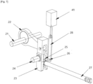
- FIG. 3 there is shown yet another embodiment of a needling machine comprising a control system according to the invention.
- the housing is shown in a sectional view, while the rest of the needling machine is shown in a front view.
- This needling machine comprises two 10" needle boards comprising 1" needles projecting from the underside of their respective board being arranged either in rows and columns, or randomly or pseudo-randomly, as is well known in the domain.
- Each 10" needle board is carried by a 2" beam, called a moving beam.
- the respective 2" beam and 10" plank are attached to each other, in a removable manner to allow, when the needles are worn and/or broken, to easily replace a plank with a new plank.
- the needles are intended to have a back and forth movement with an elliptical trajectory from top to bottom and from bottom to top to cross in one direction, then in the other, a sheet or a veil of fibers which are made pass in front of it in a direction of lead or MD, namely from left to right in the horizontal direction to the figure.
- Two longitudinal columns 3′′ extending along a vertical longitudinal axis 11′′ perpendicular to the plane of the board are each connected to a respective movable beam 2′′ via two respective vertical intermediate links 9 .
- Each vertical 9" link is articulated, on the one hand, at its upper end to the lower end of a respective 3" column and, on the other hand, at its lower end at a point 17" from the upper part of a respective movable 2" beam.
- First longitudinal drive means are provided to impart to each column 3" a rectilinear back and forth movement in a direction parallel to the longitudinal axis 11", which remains vertical throughout the movement.
- a sealed casing 7" encloses the first drive means and a part of each column 3", the latter passing through the wall of the casing 7" by passing through respective guide pots 4".
- Each 4" guide pot is mounted fixed in relation to the housing.
- Each 3" column during its movement back and forth vertically, slides inside the respective 4" guide pot.
- 18" guide rings are arranged on the inner wall of the 4" guide pot, to ensure sliding and lubrication between the 3" column and the 4" guide pot. Sealing between the 3" column and the 4" guide pot is ensured by a gasket not shown attached to the base of the guide pot.
- the first longitudinal drive means consist of two 6" systems with eccentric shafts, the shafts of which drive the heads of two connecting rods by rotating at the same speed in opposite directions.
- the feet of the two connecting rods are mounted hinged to a respective column .
- first vertical longitudinal drive means make it possible to impart to each column 3′′ a movement only back and forth along the vertical longitudinal axis.
- Second transverse drive means are also provided in the form of a main link 8" arranged in the direction MD.
- One end of the link 8" is hingedly mounted at the point 17" of articulation of the upper part of the one of the 2" movable beams to the vertical link.
- This movable beam 2" is thus given a back and forth movement in the direction MD, or substantially in the direction MD (as represented by the double arrow above the connecting rod 8" at the picture 3 ).
- the other end of the 8" rod is coupled to a control system, called the advance system, which can be like those shown below in figures 5 to 7 .
- a 20" auxiliary connecting rod is hinged on the one hand to the end of the main 8" connecting rod, in particular at point 17" of the mobile 2" beam, and on the other hand to the other mobile part, thus also transmitting to the latter the back and forth movement towards MD.
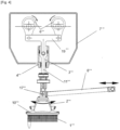
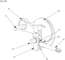
- FIG 4 there is shown another embodiment of a needling machine according to the invention.
- the housing is shown in a sectional view, while the rest of the needling machine is shown in a front view.
- This needling machine comprises a 10'" needle board comprising needles 1′′′ projecting from the underside of their respective board being arranged either in rows and columns, or randomly or pseudo-randomly, as is well known.
- the 10'" needle board is carried by a 2′′′ beam, called a moving beam.
- the 2'" beam and 10'" plank are integral with each other, in a removable manner to allow, when the needles are worn and/or broken, to easily replace a plank with a new one.
- the needles are intended to have a back and forth movement with an elliptical trajectory from top to bottom and from bottom to top to cross in one direction, then in the other, a sheet or a veil of fibers which are made pass in front of it in a direction of lead or MD, namely from left to right in the horizontal direction to the figure.
- a longitudinal column 3'' extending along a vertical longitudinal axis 11'' perpendicular to the plane of the board, is connected to the movable beam 2'' by means of a vertical intermediate rod 9''.
- the vertical rod 9′′′ is articulated, on the one hand, at its upper end to the lower end of the column 3'" and, on the other hand, at its lower end at a point 17'" from the upper part of the mobile 2'" beam.
- First longitudinal drive means are provided to impart to the column 3'" a rectilinear back and forth movement in a direction parallel to the longitudinal axis 11′′′, which remains vertical throughout the movement.
- a sealed casing 7′′′ encloses the first drive means and a part of the column 3′′′, the latter passing through the wall of the casing 7'" by passing through a respective guide pot 4'".
- the 4'" guide pot is mounted fixed relative to the casing.
- the 3′′′ column during its movement back and forth vertically, slides inside the 4'" guide pot.
- 18'" guide rings are arranged on the inside wall of each 4'" guide pot, to ensure sliding and lubrication between the column 3′′′ and the pot 4 '" respective guide. Sealing between column 3' and guide pot 4'" is ensured by a seal, not shown, attached to the base of the guide pot.
- the first longitudinal drive means consist of two 6'" systems with eccentric shafts, the shafts of which drive the heads of two connecting rods by rotating at the same speed in opposite directions.
- the feet of the two connecting rods are mounted articulated at the a respective one of the side branches of a 19'" T-link, while the main branch or rod of the T-link is hinged to the 3′′′ column.
- Second transverse drive means are also provided in the form of a main link 8′′ arranged in the direction MD.
- One end of the link 8′′′ is hingedly mounted at the point upper part of the mobile beam 2'" to the vertical connecting rod.
- This mobile beam 2'" is thus given a back and forth movement in the direction MD, or substantially in the direction MD (as represented by the double arrow above).
- the other end of the rod 8′′′ is coupled to a control system, called the advance system, which can be in particular like those represented below in figures 5 to 7 .
- the system comprises an eccentric shaft 21 coupled to a connecting rod 22 mounted articulated directly to a vertical lever 23 in one piece (or possibly consisting of several parts which are not articulated together) arranged to pivot relative to an axis 24 fixed pivot offset, in the vertical direction, below the axis of articulation of the connecting rod 22 to the lever 23.
- a connecting rod 27 is coupled directly to the lever 23.
- the connecting rod 27 is integral a slider 25 and one end of a rod 26 whose axis extends parallel to the axis 24.
- the relative position of the rod 26, and therefore also of the link 27, with respect to the pivot axis 24 of the lever along the vertical direction and/or with respect to the axis of articulation of the link 22 at the lever can be adjusted by means of an adjustment system consisting of an eccentric shaft 29 auxiliary adjustment and a rod 28 adjustment.
- the adjusting rod 28 is articulatedly coupled at its upper end to the eccentric shaft (or crankshaft) 29, while its lower end is pivotally mounted relative to the axis of the rod 26.
- the lever has an opening in the form of a slot 30, in which slides the slider 25 integral in translation with the rod 26.
- the amplitude of the back and forth movement of the link 27 can be varied both when running and when stopped, the movement reflected from the movement of the crankshaft 21 and the link 22 acting on the lever 23.
- the link 27 it can be secured or articulated to any one of the links 8, 8' and 8" of the embodiments of the figure 1 , 2 And 3 .
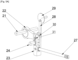
- FIG. 5A there is shown a variant of the arrangement of the figure 5 .
- the adjustment of the distance between the connecting rod 22 and the driving connecting rod 27 is carried out by adjusting the position along the slot 30 of the axis 31 of articulation of the connecting rod 22 on the lever 23 , which makes it possible to adjust the distance between the axis 31 of articulation of the link 22 and the fixed axis 24 of pivoting of the lever, and therefore also to adjust the distance between the axis 31 and the link 27, the distance between the link 27 and the axis 24 being, in this variant, fixed, whereas in the embodiment of the figure 5 , it is the distance between the axis 31 and the axis 24 which is fixed.
- FIG. 5B there is shown a variant of the arrangement of the figure 5 .
- the adjustment of the distance between the connecting rod 22 and the driving rod 27 is carried out by adjusting the position along a slot 30' formed in the lever 23 of the fixed pivot axis 24 of the lever.
- the axis 24 of the lever is integral with a slider 25' mounted to slide in the slot 30'.
- the connecting rod 22 is articulated to the lever 23 along an axis 31 of articulation which is in a fixed position on the lever 23.
- the end of articulation of the connecting rod 27 to the lever 23 is in a fixed position (as in the embodiment of there figure 5 ).
- the rod 26 from the rod 28 adjustment is articulated to the lever 23 in a fixed position.
- a spiral cam is used, consisting of a disc 40 in which is provided a spiral-shaped slot along which the rod 26 can move.
- the rod 26 follows the profile of the spiral slot, which has the effect of moving the rod 26 and therefore the slider 25 along the slot 30.
- FIG 7 there is shown yet another embodiment, in which a cylinder 41 is used instead of the crankshaft 29 of the figure 5 , the rest of the embodiment being identical.
- control or advance device or system according to the invention is represented here in combination with the needle looms of the figures 1 to 4 .
- it can also be used with other needling machines known from the prior art, for example those known from EP-A1-1736586 , EP-B1-3372716 , FR2738846 , US6161269 and the like. So, for example, at the figure 8 , there is shown yet another embodiment of a needling machine comprising a control system according to the invention.
- the casing is shown there in a sectional view, while the rest of the needling machine is shown in a front view.
- This needling machine comprises two needle boards 110 comprising needles 101 protruding from the underside of their respective board being arranged either in rows and columns, or randomly or pseudo-randomly, as is well known in the field. .
- Each needle board 110 is carried by a beam 102, called a moving beam.
- the respective beam 102 and board 110 are integral with each other, in a removable manner to allow, when the needles are worn and/or broken, to easily replace a board with a new board.
- the needles are intended to move back and forth vertically from top to bottom and from bottom to top to cross in one direction, then in the other, a sheet or veil of fibers which are passed in front of it in a feed direction or MD, namely from left to right in the horizontal direction to the figure.
- Two longitudinal columns 103 extending along a vertical longitudinal axis 111 perpendicular to the plane of the board, are each secured to a respective movable beam 102.
- Longitudinal drive means are provided to impart to each column 103 a rectilinear back and forth movement in a vertical direction parallel to the longitudinal axis 111, which remains vertical throughout the movement.
- a sealed casing 107 encloses the drive means and part of each column 103, the latter passing through the wall of the casing 107 by passing through respective guide pots 104 .
- Each guide pot 104 is mounted fixed relative to the housing.
- Each column 103 during its movement back and forth vertically, slides inside the pot 104 of the respective guide.
- Guide rings 118 are arranged on the inner wall of each pot 104 guide, to ensure sliding and lubrication between the column 103 and the pot 104 of the respective guide.
- the seal between the column 103 and the guide pot 4′′ is provided by a gasket, not shown, attached to the base of the guide pot.
- the longitudinal drive means consist of two systems 106 with eccentric shafts, the shafts of which drive the heads of two connecting rods by rotating at the same speed in opposite directions.
- the legs of the two connecting rods are hingedly connected to a respective column.
- Means for controlling, in particular adjusting, the stroke of the needles are also provided. These control means are arranged between the drive means 106 and each column 103. They comprise a lever 123 to which the connecting rod 122 of the shaft 106 is hingedly mounted. The lever 123 is pivotable with respect to a pivot axis 124 offset with respect to the axis of the articulation of the connecting rod 122 to the lever 123. A connecting rod 127 is coupled to the lever 123. The connecting rod 127 is integral with a slider 125 and one end of a rod 126 whose axis extends parallel to the axis 124.
- the lever has an opening in the form of a slot 130, in which slides the slider 125 integral in translation with the rod 126 (rod 126 which can be seen better on the figure 7 which describes the same control means which comprises a rod 26 corresponding to this rod 126).
- the relative position of the rod 126 with respect to the axis 124 along the lever can be adjusted by means of an adjustment system consisting of a cylinder 141 and an adjustment rod 128, coupled in an articulated manner at one end to the cylinder 141 and at its other end to the rod 126 pivotally.
- the relative position of the slider 125 in the slot 130 so as to adjust the distance along the lever between the axis 124 and the axis of the rod 126, this distance thus being able to vary between a minimum value (the slider 125 is located at one end of the slot so as to have the axis of the rod 126 as close as possible to the axis 124 and a maximum adjustment position, in which the slider 125 is at the other end of the slot, as far as possible from the axis 124.
- the amplitude of the back and forth movement of the link 127 can be varied both when running and when stopped, the movement reflected from the movement of the cylinder 141 and the link 122 acting on the lever 123.
- a feed control device in the embodiments of the figures 1 to 4 to control the vertical movements of the columns of the elliptical needle looms described therein.
Description
La présente invention se rapporte à un dispositif de commande du déplacement suivant une trajectoire des aiguilles d'une aiguilleteuse, notamment de la composante suivant la direction MD du déplacement suivant une trajectoire elliptique des aiguilles d'une aiguilleteuse à mouvement elliptique, ainsi qu'à une aiguilleteuse, notamment elliptique, comportant un dispositif de commande de ce genre.The present invention relates to a device for controlling the movement along a trajectory of the needles of a needling machine, in particular the component along the direction MD of the movement along an elliptical trajectory of the needles of a needling machine with elliptical movement, as well as to a needling machine, in particular an elliptical, comprising a control device of this kind.
Classiquement, une aiguilleteuse elliptique pour consolider par aiguilletage un voile ou une nappe de fibres, notamment de non-tissé, comporte au moins une planche à aiguilles, en face de laquelle le voile ou la nappe de fibres passe en se déplaçant dans une direction d'avance ou direction machine ou MD, et des moyens d'entraînement configurés pour donner à la au moins une planche à aiguilles et/ou aux aiguilles un mouvement en va et vient dans la direction perpendiculaire ou sensiblement perpendiculaire au plan de la nappe ou du voile pour que les aiguilles traversent dans un sens, puis dans l'autre, le voile ou la nappe de fibres, en ayant une trajectoire elliptique. De
Pour donner aux planches et aux aiguilles par exemple un mouvement elliptique, il est prévu des moyens d'entraînement MD configurés pour impartir aux aiguilles et/ou à la planche à aiguilles la composante MD de leur mouvement elliptique.To give the boards and the needles, for example, an elliptical movement, there are provided drive means MD configured to impart to the needles and/or the needle board the MD component of their elliptical movement.
Les moyens d'entraînement MD connus sont de structure complexe et prennent beaucoup de place. On aimerait avoir à disposition un dispositif d'entraînement de structure plus simple, qui permet notamment son réglage aussi bien en marche qu'à l'arrêt. En outre, dans certains cas, on souhaite placer ces moyens d'entraînement MD dans un carter étanche, aux côtés des moyens d'entraînement des planches suivant la direction longitudinale, et pour ce faire une structure plus compacte est recherchée.Known MD drive means are complex in structure and take up a lot of space. We would like to have available a driving device with a simpler structure, which in particular allows its adjustment both on and off. In addition, in some cases, it is desired to place these drive means MD in a sealed casing, alongside the means for driving the boards in the longitudinal direction, and to do this a more compact structure is sought.
Suivant l'invention, un dispositif de commande de la composante suivant une direction donnée, par exemple la direction MD, du déplacement suivant une trajectoire donnée, par exemple elliptique, des aiguilles d'une aiguilleteuse, par exemple une aiguilleteuse elliptique, destinée à consolider par aiguilletage un voile ou une nappe de fibres, notamment de non-tissé, comportant au moins une planche à aiguilles ayant un champ d'aiguilles et des moyens d'entraînement configurés pour impartir à la au moins une planche à aiguilles et/ou aux aiguilles un mouvement de va-et-vient de sorte que les aiguilles aient une trajectoire donnée, par exemple elliptique, pour traverser dans un sens, puis dans l'autre, le voile ou la nappe de fibres qui se déplace devant elles suivant une direction machine ou d'amenée MD pour le ou la consolider, le dispositif de commande étant tel que défini à la revendication 1.According to the invention, a device for controlling the component in a given direction, for example the direction MD, of the movement along a given trajectory, for example elliptical, of the needles of a needling machine, for example an elliptical needling machine, intended to consolidate by needling a veil or a layer of fibres, in particular of nonwoven, comprising at least one needle board having a field of needles and drive means configured to impart to the at least one needle board and/or to the needles a back and forth movement so that the needles have a given trajectory, for example elliptical, to cross in one direction, then in the other, the veil or the web of fibers which moves in front of them in one direction machine or feed MD to consolidate it, the control device being as defined in
Suivant un mode de réalisation favorable, ladite une direction donnée est la direction MD et ladite une trajectoire donnée est elliptique, les moyens d'entraînement comportant des moyens d'entraînement MD configurés pour impartir à la au moins une planche et/ou aux aiguilles la composante MD de leur mouvement elliptique.According to a favorable embodiment, said one given direction is the MD direction and said one given trajectory is elliptical, the drive means comprising MD drive means configured to impart to the at least one board and/or to the needles the MD component of their elliptical motion.
Suivant un autre mode de réalisation favorable, ladite une direction donnée est la direction verticale et ladite une trajectoire donnée est rectiligne. Le mouvement des aiguilles étant en va et vient suivant la direction verticale.According to another favorable embodiment, said one given direction is the vertical direction and said one given trajectory is rectilinear. The movement of the hands being back and forth in the vertical direction.
Des perfectionnements et modes de réalisation avantageux sont définis aux sous revendications.Advantageous improvements and embodiments are defined in the subclaims.
La présente invention se rapporte également à une aiguilleteuse, notamment elliptique, comportant un dispositif de commande suivant l'invention.The present invention also relates to a needling machine, in particular an elliptical, comprising a control device according to the invention.
En particulier, l'aiguilleteuse comporte une ou plusieurs colonnes à laquelle ou auxquelles est ou sont reliées une ou des planches à aiguilles respectives, notamment de manière basculante, des moyens d'entraînement longitudinal étant prévus pour impartir à la ou chaque colonne un mouvement de va et vient suivant une direction parallèle à l'axe longitudinal de la colonne, au moins une partie de la ou de chaque colonne et les moyens d'entraînement longitudinal étant reçu dans un carter étanche, dans lequel le dispositif de commande MD est aussi reçu dans le carter étanche.In particular, the needling machine comprises one or more columns to which one or more respective needle boards are connected, in particular in a tilting manner, longitudinal drive means being provided to impart to the or each column a movement of moves back and forth in a direction parallel to the longitudinal axis of the column, at least part of the or each column and the longitudinal drive means being housed in a sealed casing, in which the control device MD is also housed in the sealed housing.
Suivant l'invention, on obtient ainsi un système moins complexe que ceux de l'art antérieur, notamment d'un point de vue mécanique, et qui en outre est plus compact. En particulier, il n'est plus nécessaire de réaliser un déphasage entre deux arbres à excentrique.According to the invention, a less complex system is thus obtained than those of the prior art, in particular from a mechanical point of view, and which is moreover more compact. In particular, it is no longer necessary to achieve a phase shift between two eccentric shafts.
A titre d'exemple, on décrit maintenant des modes de réalisation préférés de l'invention en se reportant aux dessins dans lesquels :
- La
figure 1 est une vue d'ensemble de face partiellement en coupe et écorchée, d'un dispositif d'aiguilletage comportant un dispositif de commande suivant un mode de réalisation de l'invention ; - La
figure 1A est une vue à plus grande échelle d'une partie de lafigure 1 ; - La
figure 2 est une vue d'ensemble de face partiellement en coupe et écorchée, d'un autre dispositif d'aiguilletage comportant un dispositif de commande suivant un mode de réalisation de l'invention ; - La
figure 2A est une vue d'ensemble de face, partiellement en coupe et écorchée, d'un dispositif d'aiguilletage suivant encore un autre mode de réalisation de réalisation suivant l'invention ; - La
figure 3 est une vue d'ensemble de face partiellement en coupe, d'encore un autre dispositif d'aiguilletage comportant un dispositif de commande suivant un mode de réalisation de l'invention ; - La
figure 4 est une vue d'ensemble de face partiellement en coupe, d'encore un autre dispositif d'aiguilletage comportant un dispositif de commande suivant un mode de réalisation de l'invention ; - La
figure 5 est une vue d'ensemble en perspective d'un mode réalisation d'un système de commande suivant l'invention ; - La
figure 5A est une vue d'ensemble en perspective d'un autre mode de réalisation d'un système de commande suivant l'invention ; - La
figure 5B est une vue d'ensemble en perspective d'encore un autre mode de réalisation d'un système de commande suivant l'invention ; - La
figure 6A est une vue d'ensemble d'un autre mode de réalisation d'un système de commande suivant l'invention ; - La
figure 6B est une vue de l'arrière du système de commande de lafigure 6A ; et - La
figure 7 est une vue d'ensemble d'encore une autre mode de réalisation d'un système de commande suivant l'invention ; - La
figure 8 est vue d'ensemble de face partiellement en coupe, d'un dispositif d'aiguilletage comportant un dispositif de commande suivant l'invention.
- There
figure 1 is an assembly front view, partially in section and cut away, of a needling device comprising a control device according to one embodiment of the invention; - There
Figure 1A is a larger scale view of part of thefigure 1 ; - There
figure 2 is an assembly front view, partially in section and cut away, of another needling device comprising a control device according to one embodiment of the invention; - There
figure 2A is an overall front view, partially in section and cut away, of a needling device according to yet another embodiment according to the invention; - There
picture 3 - There
figure 4 is a front assembly view, partially in section, of yet another needling device comprising a control device according to one embodiment of the invention; - There
figure 5 is an overall perspective view of one embodiment of a control system according to the invention; - There
figure 5A is an overall perspective view of another embodiment of a control system according to the invention; - There
figure 5B is an overall perspective view of yet another embodiment of a control system according to the invention; - There
Figure 6A is an overview of another embodiment of a control system according to the invention; - There
figure 6B is a rear view of the control system of theFigure 6A ; And - There
figure 7 is an overview of yet another embodiment of a control system according to the invention; - There
figure 8 is an overall front view, partially in section, of a needling device comprising a control device according to the invention.
A la
Cette aiguilleteuse comporte une planche 10 à aiguilles comportant des aiguilles 1 faisant saillie de la face inférieure de la planche en étant agencées soit suivant des rangées et des colonnes, soit de manière aléatoire ou pseudo-aléatoire, comme il est bien connu dans le domaine. La planche 10 à aiguilles est portée par une poutre 2, dite poutre mobile. Les poutre 2 et planche 10 sont solidaires l'une de l'autre, mais de manière amovible, pour permettre, lorsque les aiguilles sont usées et/ou cassées, de remplacer facilement une planche par une nouvelle planche. Les aiguilles sont destinées à avoir un mouvement de va-et-vient à trajectoire elliptique de haut en bas et de bas en haut pour traverser dans un sens, puis dans l'autre, une nappe ou un voile de fibres que l'on fait passer devant elles dans une direction d'amenée ou MD, à savoir de gauche à droite en direction horizontale à la figure.This needling machine comprises a
Une colonne 3 longitudinale s'étendant suivant un axe longitudinal 11 perpendiculaire au plan de la planche est solidarisée à la poutre 2 mobile, de sorte que les mouvements de la colonne 3, de la poutre 2 mobile, de la planche 10 à aiguilles et des aiguilles sont identiques, à savoir avec une même trajectoire elliptique.A
Des moyens d'entraînement sont prévus pour impartir à la colonne 3 (et donc également à la planche 10 à aiguilles, à la poutre 2 mobile et aux aiguilles 1) un mouvement ayant une composante suivant une direction parallèle à l'axe longitudinal 11 et une composante suivant la direction MD, de manière à avoir une trajectoire elliptique comme représenté à la
Un carter 7 étanche enferme les moyens d'entraînement et une partie de la colonne 3, cette dernière traversant la paroi du carter 7 en traversant un pot 4 de guidage, dont l'interface avec le carter 7 est rendue étanche par l'intermédiaire d'un joint d'étanchéité qui suivant un mode de réalisation possible peut prendre la forme d'un joint 50 à soufflet. Le pot 4 de guidage est monté basculant par rapport à un axe 5 fixe par rapport au carter 7, parallèle à la direction CD (perpendiculaire à la direction MD et à l'axe longitudinal 11). La colonne 3 peut coulisser à l'intérieur du pot 4 de guidage. Des bagues 16 de guidage sont disposées sur la paroi intérieure du pot 4 de guidage, pour assurer le glissement et la lubrification entre la colonne 3 et le pot 4 de guidage. L'étanchéité entre la colonne 3 et le pot 4 de guidage est assuré par un joint d'étanchéité non représenté fixé à la base du pot de guidage.A sealed
De manière très favorable, notamment en terme de longévité de l'étanchéité du carter, l'axe 5 fixe est positionné sensiblement au niveau de l'ouverture du carter traversée par le pot 4 de guidage, notamment dans l'ouverture.Very favorably, particularly in terms of longevity of the sealing of the casing, the
Les moyens d'entraînement comportent des premiers moyens d'entraînement longitudinal configurés pour impartir un mouvement de va-et-vient à la colonne suivant une direction parallèle à l'axe longitudinal. Ces premiers moyens d'entraînement sont constitués de deux systèmes 6 à arbres 12 à excentrique et bielles 13 et d'une biellette 9 intermédiaire.The drive means comprise first longitudinal drive means configured to impart a reciprocating movement to the column in a direction parallel to the longitudinal axis. These first drive means consist of two
Les arbres 12 entraînent les têtes des deux bielles 13 en tournant (comme représenté par les deux flèches en haut de la
Ces premiers moyens d'entraînement longitudinal permettent d'impartir à la colonne 3 un mouvement uniquement en va-et-vient suivant l'axe longitudinal.These first longitudinal drive means make it possible to impart to the column 3 a movement only back and forth along the longitudinal axis.
Il est prévu en outre des deuxièmes moyens d'entraînement transversal sous la forme d'une biellette 8 principale disposée suivant la direction MD. Une extrémité de la biellette 8 est montée articulée au pot 4 de guidage, à l'intérieur du carter 7, en un point 17 à distance de l'axe 5 de rotation du pot, notamment sensiblement à l'extrémité supérieure du pot. Il est ainsi imparti au pot 4 de guidage un mouvement d'oscillation en va et vient qui se traduit sur la colonne 3 qui le traverse par un mouvement en va et vient suivant la direction MD, ou sensiblement suivant la direction MD (comme représenté par la double flèche au-dessus de la biellette 8 à la
D'autre part, une masse 19 d'équilibrage du système est couplée au pot 4 de guidage, en étant fixé à ce dernier du côté opposé à celui où se trouve le système d'avance.On the other hand, a
Enfin, le système d'avance étant reçu dans le carter étanche, il peut être actionné soit par un moteur indépendant, soit par un des arbres 6 de commande des premiers moyens d'entraînement vertical, soit par une bielle montée directement sur un excentrique solidaire d'un des arbres 6 de commande des premiers moyens d'entraînement.Finally, the advance system being housed in the sealed casing, it can be actuated either by an independent motor, or by one of the
A la
Cette aiguilleteuse comporte deux planches 10' à aiguilles comportant des aiguilles 1' faisant saillie de la face inférieure de la planche en étant agencées soit suivant des rangées et des colonnes, soit de manière aléatoire ou pseudo-aléatoire, comme il est bien connu dans le domaine. Chaque planche 10' à aiguilles est portée par une poutre 2' respective, dite poutre mobile. Les aiguilles sont destinées à avoir un mouvement de va-et-vient à trajectoire elliptique de haut en bas et de bas en haut pour traverser dans un sens, puis dans l'autre, une nappe ou un voile de fibres que l'on fait passer devant elle dans une direction d'amenée ou MD, à savoir de gauche à droite en direction horizontale à la figure.This needling machine comprises two needle boards 10' comprising needles 1' protruding from the underside of the board being arranged either in rows and columns, or randomly or pseudo-randomly, as is well known in the domain. Each needle board 10' is carried by a respective beam 2', called a moving beam. The needles are intended to have a back and forth movement with an elliptical trajectory from top to bottom and from bottom to top to cross in one direction, then in the other, a sheet or a veil of fibers which are made pass in front of it in a direction of lead or MD, namely from left to right in the horizontal direction to the figure.
Deux colonnes 3' longitudinales s'étendent suivant des axes longitudinaux 11' perpendiculaire au plan de la planche. Les colonnes 3' sont solidarisées chacune à une poutre 2' mobile, de sorte que les mouvements de la colonne 3', de la poutre 2' mobile, de la planche 10' à aiguilles et des aiguilles sont identiques, à savoir avec une même trajectoire elliptique.Two longitudinal columns 3' extend along longitudinal axes 11' perpendicular to the plane of the board. The columns 3' are each secured to a mobile beam 2', so that the movements of the column 3', of the beam 2 'mobile, the board 10' needles and needles are identical, namely with the same elliptical trajectory.
Des moyens d'entraînement sont prévus pour impartir à chaque colonne 3' (et donc également aux planches 10' à aiguilles, aux poutres 2' mobile et aux aiguilles 1) un mouvement ayant une composante suivant une direction parallèle à l'axe longitudinal 11' et une composante suivant la direction MD, de manière à avoir une trajectoire elliptique comme représenté à la
Un carter 7' étanche enferme les moyens d'entraînement et une partie des colonnes 3', ces dernières traversant la paroi du carter 7' en traversant des pots 4' de guidage respectifs, dont les interfaces avec le carter 7' sont rendues étanches par l'intermédiaire de joints d'étanchéité (non représentés, mais qui par exemple peuvent être réalisés sous la forme de joints à soufflet comme représenté à la
Les moyens d'entraînement comportent des premiers moyens d'entraînement longitudinal configurés pour impartir un mouvement de va-et-vient à chaque colonne suivant une direction parallèle à l'axe longitudinal. Ces premiers moyens d'entraînement sont constitués de deux systèmes 6' à arbres 12' à excentrique et bielles 13'.The drive means comprise first longitudinal drive means configured to impart a reciprocating movement to each column in a direction parallel to the longitudinal axis. These first drive means consist of two systems 6' with eccentric shafts 12' and connecting rods 13'.
Les arbres 12' entraînent les têtes des deux bielles 13' en tournant (comme représenté par les deux flèches en haut de la
Ces premiers moyens d'entraînement longitudinal vertical permettent d'impartir à chaque colonne 3' un mouvement en va-et-vient suivant une direction principalement parallèle à l'axe longitudinal.These first vertical longitudinal drive means make it possible to impart to each column 3' a back-and-forth movement in a direction mainly parallel to the longitudinal axis.
Il est prévu en outre des deuxièmes moyens d'entraînement transversal sous la forme d'une biellette 8' principale et d'une biellette 9' auxiliaire qui sont disposées suivant la direction MD et qui se trouvent à l'intérieur du carter 7'. Une extrémité de la biellette 8' est montée articulée à l'un des pots 4' de guidage en un point 17' à distance de l'axe 5' de rotation du pot, notamment sensiblement à l'extrémité supérieure du pot. L'autre extrémité de la biellette 8' est couplée à un système de commande, appelé système d'avance, qui est l'un quelconque de ceux représentés ci-après aux
La biellette 9' auxiliaire est montée articulée à ses deux extrémités opposées à l'un respectif des pots 4'. En particulier, la biellette 9' est articulée également à l'extrémité de la biellette 8' articulée au point 17'.The auxiliary link 9' is mounted articulated at its two opposite ends to a respective one of the pots 4'. In particular, link 9' is also articulated at the end of link 8' articulated at point 17'.
Il est ainsi imparti aux deux pots 4' de guidage un mouvement d'oscillation en va et vient qui se traduit sur les colonnes 3' qui les traversent par un mouvement en va et vient suivant la direction MD, ou sensiblement suivant la direction MD (comme représenté par la double flèche au-dessus de la biellette 8' à la
D'autre part, une masse 19' d'équilibrage du système est couplée à la biellette 9'auxiliaire, en étant fixée à cette dernière du côté supérieur à mi- distance des deux arbres 12'.On the other hand, a mass 19' for balancing the system is coupled to the auxiliary link 9', being fixed to the latter on the upper side at mid-distance of the two shafts 12'.
Enfin, le système d'avance étant reçu dans le carter étanche, il peut être actionné soit par un moteur indépendant, soit par un des arbres 12' de commande des premiers moyens d'entraînement vertical, soit par une bielle montée directement sur un excentrique solidaire d'un des arbres 12' de commande des premiers moyens d'entraînement.Finally, the advance system being housed in the sealed casing, it can be actuated either by an independent motor, or by one of the control shafts 12' of the first vertical drive means, or by a connecting rod mounted directly on an eccentric secured to one of the control shafts 12' of the first drive means.
En particulier, comme représenté à la
Dans la description ci-dessus, les premiers moyens d'entraînement longitudinal sont distincts des deuxièmes moyens d'entraînement transversal. Bien que cette séparation en deux moyens distincts présente des avantages, il est cependant envisageable de prévoir des moyens uniques qui réalisent les deux fonctions des premiers et deuxièmes moyens, sans sortir du cadre de l'invention tel que défini par les revendications.In the above description, the first longitudinal drive means are distinct from the second transverse drive means. Although this separation into two separate means has advantages, it is however possible to provide single means which perform the two functions of the first and second means, without departing from the scope of the invention as defined by the claims.
A la
Cette aiguilleteuse comporte deux planches 10" à aiguilles comportant des aiguilles 1" faisant saillie de la face inférieure de leur planche respective en étant agencées soit suivant des rangées et des colonnes, soit de manière aléatoire ou pseudo-aléatoire, comme il est bien connu dans le domaine. Chaque planche 10" à aiguilles est portée par une poutre 2", dite poutre mobile. Les poutre 2" et planche 10" respectives sont solidaires l'une de l'autre, de manière amovible pour permettre, lorsque les aiguilles sont usées et/ou cassées, de remplacer facilement une planche par une nouvelle planche. Les aiguilles sont destinées à avoir un mouvement de va-et-vient à trajectoire elliptique de haut en bas et de bas en haut pour traverser dans un sens, puis dans l'autre, une nappe ou un voile de fibres que l'on fait passer devant elle dans une direction d'amenée ou MD, à savoir de gauche à droite en direction horizontale à la figure.This needling machine comprises two 10" needle boards comprising 1" needles projecting from the underside of their respective board being arranged either in rows and columns, or randomly or pseudo-randomly, as is well known in the domain. Each 10" needle board is carried by a 2" beam, called a moving beam. The respective 2" beam and 10" plank are attached to each other, in a removable manner to allow, when the needles are worn and/or broken, to easily replace a plank with a new plank. The needles are intended to have a back and forth movement with an elliptical trajectory from top to bottom and from bottom to top to cross in one direction, then in the other, a sheet or a veil of fibers which are made pass in front of it in a direction of lead or MD, namely from left to right in the horizontal direction to the figure.
Deux colonnes 3" longitudinales s'étendant suivant un axe 11" longitudinal vertical perpendiculaire au plan de la planche sont chacune reliée à une poutre 2" mobile respective par l'intermédiaire de deux biellettes 9 intermédiaires verticales respectives.Two
Chaque biellette 9" verticale est articulée, d'une part, à son extrémité supérieure à l'extrémité inférieure d'une colonne 3" respective et, d'autre part, à son extrémité inférieure à un point 17" de la partie supérieure d'une poutre 2" mobile respective.Each vertical 9" link is articulated, on the one hand, at its upper end to the lower end of a respective 3" column and, on the other hand, at its lower end at a
Des premiers moyens d'entraînement longitudinal sont prévus pour impartir à chaque colonne 3" un mouvement de va et vient rectiligne suivant une direction parallèle à l'axe 11" longitudinal, qui reste vertical pendant tout le mouvement.First longitudinal drive means are provided to impart to each
Un carter 7" étanche enferme les premiers moyens d'entraînement et une partie de chaque colonne 3", ces dernières traversant la paroi du carter 7" en traversant des pots 4" de guidage respectifs. Chaque pot 4" de guidage est monté fixe par rapport au carter. Chaque colonne 3", lors de son mouvement en va et vient vertical, coulisse à l'intérieur du pot 4" de guidage respectif. Des bagues 18" de guidage sont disposées sur la paroi intérieure du pot 4" de guidage, pour assurer le glissement et la lubrification entre la colonne 3" et le pot 4" de guidage. L'étanchéité entre la colonne 3" et le pot 4" de guidage est assuré par un joint d'étanchéité non représenté fixé à la base du pot de guidage.A sealed
Les premiers moyens d'entraînement longitudinal sont constitués de deux systèmes 6" à arbres à excentrique, dont les arbres entraînent les têtes de deux bielles en tournant à même vitesse dans des sens opposés. Les pieds des deux bielles sont montés articulés à une colonne respective.The first longitudinal drive means consist of two 6" systems with eccentric shafts, the shafts of which drive the heads of two connecting rods by rotating at the same speed in opposite directions. The feet of the two connecting rods are mounted hinged to a respective column .
Ces premiers moyens d'entraînement longitudinal vertical permettent d'impartir à chaque colonne 3" un mouvement uniquement en va-et-vient suivant l'axe longitudinal vertical.These first vertical longitudinal drive means make it possible to impart to each
Il est prévu en outre des deuxièmes moyens d'entraînement transversal sous la forme d'une biellette 8" principale disposée suivant la direction MD. Une extrémité de la biellette 8" est montée articulée au point 17" d'articulation de la partie supérieure de l'une des poutres 2" mobiles à la biellette verticale. Il est ainsi imparti à cette poutre mobile 2" un mouvement en va et vient suivant la direction MD, ou sensiblement suivant la direction MD (comme représenté par la double flèche au-dessus de la biellette 8" à la
A la
Cette aiguilleteuse comporte une planche 10'" à aiguilles comportant des aiguilles 1‴ faisant saillie de la face inférieure de leur planche respective en étant agencées soit suivant des rangées et des colonnes, soit de manière aléatoire ou pseudo-aléatoire, comme il est bien connu dans le domaine. La planche 10'" à aiguilles est portée par une poutre 2‴, dite poutre mobile. Les poutre 2'" et planche 10'" sont solidaires l'une de l'autre, de manière amovible pour permettre, lorsque les aiguilles sont usées et/ou cassées, de remplacer facilement une planche par une nouvelle planche. Les aiguilles sont destinées à avoir un mouvement de va-et-vient à trajectoire elliptique de haut en bas et de bas en haut pour traverser dans un sens, puis dans l'autre, une nappe ou un voile de fibres que l'on fait passer devant elle dans une direction d'amenée ou MD, à savoir de gauche à droite en direction horizontale à la figure.This needling machine comprises a 10'" needle
Une colonne 3'" longitudinale, s'étendant suivant un axe 11'" longitudinal vertical perpendiculaire au plan de la planche, est reliée à la poutre 2'" mobile par l'intermédiaire d'une biellette 9'" intermédiaire verticale.A longitudinal column 3'', extending along a vertical longitudinal axis 11'' perpendicular to the plane of the board, is connected to the movable beam 2'' by means of a vertical intermediate rod 9''.
La biellette 9‴ verticale est articulée, d'une part, à son extrémité supérieure à l'extrémité inférieure de la colonne 3'" et, d'autre part, à son extrémité inférieure à un point 17'" de la partie supérieure de la poutre 2'" mobile.The
Des premiers moyens d'entraînement longitudinal sont prévus pour impartir à la colonne 3'" un mouvement de va et vient rectiligne suivant une direction parallèle à l'axe 11‴ longitudinal, qui reste vertical pendant tout le mouvement.First longitudinal drive means are provided to impart to the column 3'" a rectilinear back and forth movement in a direction parallel to the
Un carter 7‴ étanche enferme les premiers moyens d'entraînement et une partie de la colonne 3‴, cette dernière traversant la paroi du carter 7'" en traversant un pot 4'" de guidage respectif. Le pot 4'" de guidage est monté fixe par rapport au carter. La colonne 3‴, lors de son mouvement en va et vient vertical, coulisse à l'intérieur du pot 4'" de guidage. Des bagues 18'" de guidage sont disposées sur la paroi intérieure de chaque pot 4'" de guidage, pour assurer le glissement et la lubrification entre la colonne 3‴ et le pot 4'" de guidage respectif. L'étanchéité entre la colonne 3‴ et le pot 4'" de guidage est assuré par un joint d'étanchéité non représenté fixé à la base du pot de guidage.A sealed
Les premiers moyens d'entraînement longitudinal sont constitués de deux systèmes 6'" à arbres à excentrique, dont les arbres entraînent les têtes de deux bielles en tournant à même vitesse dans des sens opposés. Les pieds des deux bielles sont montés articulés à l'une respective des branches latérales d'une biellette 19'" en T, tandis que la branche principale ou tige de la biellette en T est montée articulée à la colonne 3‴. Ces premiers moyens d'entraînement longitudinal vertical permettent d'impartir à la colonne 3'" un mouvement uniquement en va-et-vient suivant l'axe longitudinal vertical.The first longitudinal drive means consist of two 6'" systems with eccentric shafts, the shafts of which drive the heads of two connecting rods by rotating at the same speed in opposite directions. The feet of the two connecting rods are mounted articulated at the a respective one of the side branches of a 19'" T-link, while the main branch or rod of the T-link is hinged to the 3‴ column. These first vertical longitudinal drive means make it possible to impart to the column 3'" a movement only back and forth along the vertical longitudinal axis.
Il est prévu en outre des deuxièmes moyens d'entraînement transversal sous la forme d'une biellette 8'" principale disposée suivant la direction MD. Une extrémité de la biellette 8‴ est montée articulée au point 17'" d'articulation de la partie supérieure de la poutre 2'" mobile à la biellette verticale. Il est ainsi imparti à cette poutre mobile 2'" un mouvement en va et vient suivant la direction MD, ou sensiblement suivant la direction MD (comme représenté par la double flèche au-dessus de la biellette 8'" à la
Aux
A la
La position relative de la tige 26, et donc également de la biellette 27, par rapport à l'axe 24 de pivotement du levier le long de la direction verticale et/ou par rapport à l'axe d'articulation de la bielle 22 au levier peut être réglée par l'intermédiaire d'un système de réglage constitué d'un arbre à excentrique 29 auxiliaire de réglage et d'une biellette 28 de réglage. La biellette 28 de réglage est couplée de manière articulée à son extrémité supérieure à l'arbre à excentrique (ou vilebrequin) 29, tandis que son extrémité inférieure est montée pivotante par rapport à l'axe de la tige 26.The relative position of the
Le levier comporte une ouverture en forme de fente 30, dans lequel coulisse le coulisseau 25 solidaire en translation de la tige 26.The lever has an opening in the form of a
En fonction de la position de la biellette 28 qui est déterminée par une rotation appropriée du vilebrequin 29, on peut choisir et régler la position relative du coulisseau 25 dans la fente 30 de manière à régler la distance le long de l'axe vertical du levier entre l'axe 24 et l'axe de la tige 26 (et donc également la distance entre l'axe de la tige 26 et l'axe de la bielle 22), cette distance pouvant être variée entre une valeur nulle (position dans laquelle le coulisseau 25 se trouve en haut de la fente 30 de manière à avoir l'axe de la tige 26 en correspondance avec l'axe 24 et une position de réglage maximum, dans laquelle le coulisseau 25 se trouve tout en bas de la fente 30).Depending on the position of the
On peut faire varier l'amplitude du mouvement en va-et-vient de la biellette 27 aussi bien à la marche qu'à l'arrêt, le mouvement répercuté à partir du mouvement du vilebrequin 21 et de la biellette 22 agissant sur le levier 23. Quant à la biellette 27, elle peut être solidarisée ou articulée à l'une quelconque des biellettes 8, 8' et 8" des modes de réalisation des
A la
A la
Aux
Dans ce mode de réalisation, on utilise une came en spirale, constituée d'un disque 40 dans lequel est ménagée une fente en forme de spirale le long de laquelle la tige 26 peut se déplacer. Lors de la rotation du disque 40, la tige 26 suit le profil de la fente en spirale, ce qui a pour effet de déplacer la tige 26 et donc le coulisseau 25 le long de la fente 30. En fonction de la position choisie le long de la spirale pour la tige 26, on obtient une course donnée maximale de va et vient pour la biellette 27.In this embodiment, a spiral cam is used, consisting of a
A la
Dans les modes de réalisation décrits aux
Le dispositif ou système de commande ou d'avance suivant l'invention est représenté ici en combinaison avec les aiguilleteuses des
Le carter y est représenté suivant une vue en coupe, tandis que le reste de l'aiguilleteuse est représenté suivant une vue de face.The casing is shown there in a sectional view, while the rest of the needling machine is shown in a front view.
Cette aiguilleteuse comporte deux planches 110 à aiguilles comportant des aiguilles 101 faisant saillie de la face inférieure de leur planche respective en étant agencées soit suivant des rangées et des colonnes, soit de manière aléatoire ou pseudo-aléatoire, comme il est bien connu dans le domaine. Chaque planche 110 à aiguilles est portée par une poutre 102, dite poutre mobile. Les poutre 102 et planche 110 respectives sont solidaires l'une de l'autre, de manière amovible pour permettre, lorsque les aiguilles sont usées et/ou cassées, de remplacer facilement une planche par une nouvelle planche. Les aiguilles sont destinées à avoir un mouvement de va-et-vient vertical de haut en bas et de bas en haut pour traverser dans un sens, puis dans l'autre, une nappe ou un voile de fibres que l'on fait passer devant elle dans une direction d'amenée ou MD, à savoir de gauche à droite en direction horizontale à la figure.This needling machine comprises two
Deux colonnes 103 longitudinales, s'étendant suivant un axe 111 longitudinal vertical perpendiculaire au plan de la planche, sont chacune solidarisée à une poutre 102 mobile respective.Two
Des moyens d'entraînement longitudinal sont prévus pour impartir à chaque colonne 103 un mouvement de va et vient rectiligne suivant une direction verticale parallèle à l'axe 111 longitudinal, qui reste vertical pendant tout le mouvement.Longitudinal drive means are provided to impart to each column 103 a rectilinear back and forth movement in a vertical direction parallel to the
Un carter 107 étanche enferme les moyens d'entraînement et une partie de chaque colonne 103, ces dernières traversant la paroi du carter 107 en traversant des pots 104 de guidage respectifs. Chaque pot 104 de guidage est monté fixe par rapport au carter. Chaque colonne 103, lors de son mouvement en va et vient vertical, coulisse à l'intérieur du pot 104 de guidage respectif. Des bagues 118 de guidage sont disposées sur la paroi intérieure de chaque pot 104 de guidage, pour assurer le glissement et la lubrification entre la colonne 103 et le pot 104 de guidage respectif. L'étanchéité entre la colonne 103 et le pot 4" de guidage est assuré par un joint d'étanchéité non représenté fixé à la base du pot de guidage.A sealed
Les moyens d'entraînement longitudinal sont constitués de deux systèmes 106 à arbres à excentrique, dont les arbres entraînent les têtes de deux bielles en tournant à même vitesse dans des sens opposés. Les pieds des deux bielles sont reliés de manière articulée à une colonne respective.The longitudinal drive means consist of two
Ces moyens d'entraînement longitudinal vertical permettent d'impartir à chaque colonne 103 un mouvement uniquement en va-et-vient suivant l'axe longitudinal vertical.These vertical longitudinal drive means make it possible to impart to each column 103 a movement only back and forth along the vertical longitudinal axis.
Il est prévu en outre des moyens de commande, notamment de réglage, de la course des aiguilles. Ces moyens de commande sont disposés entre les moyens 106 d'entraînement et chaque colonne 103. Ils comportent un levier 123 auquel la bielle 122 de l'arbre 106 est montée articulée. Le levier 123 est pivotant par rapport à un axe 124 de pivotement décalé par rapport à l'axe de l'articulation de la bielle 122 au levier 123. Une biellette 127 est couplée au levier 123. La biellette 127 est solidaire d'un coulisseau 125 et d'une extrémité d'une tige 126 dont l'axe s'étend parallèlement à l'axe 124.Means for controlling, in particular adjusting, the stroke of the needles are also provided. These control means are arranged between the drive means 106 and each
Le levier comporte une ouverture en forme de fente 130, dans lequel coulisse le coulisseau 125 solidaire en translation de la tige 126 (tige 126 que l'on voit mieux à la
La position relative de la tige 126 par rapport à l'axe 124 le long du levier peut être réglée par l'intermédiaire d'un système de réglage constituée d'un vérin 141 et d'une biellette 128 de réglage, couplée de manière articulée à une extrémité au vérin 141 et à son autre extrémité à la tige 126 de manière pivotante.The relative position of the
En fonction de la position de la biellette 128 qui est déterminée par un déplacement approprié du vérin 141, on peut choisir et régler la position relative du coulisseau 125 dans la fente 130 de manière à régler la distance le long du levier entre l'axe 124 et la l'axe de la tige 126, cette distance pouvant ainsi varier entre une valeur minimale (le coulisseau 125 se trouve à une extrémité de la fente de manière avoir l'axe de la tige 126 le plus proche possible de l'axe 124 et une position de réglage maximum, dans laquelle le coulisseau 125 se trouve à l'autre extrémité de la fente, le plus loin possible de l'axe 124.Depending on the position of the
On peut faire varier l'amplitude du mouvement en va-et-vient de la biellette 127 aussi bien à la marche qu'à l'arrêt, le mouvement répercuté à partir du mouvement du vérin 141 et de la biellette 122 agissant sur le levier 123.The amplitude of the back and forth movement of the
A la
En outre, on peut, tout en restant dans le domaine de l'invention, prévoir un dispositif de commande d'avance suivant l'invention dans les modes de réalisation des
Claims (12)
- System for controlling the component in a given direction of the motion in a given path of the needles of a needling machine designed to consolidate a fleece or web of fibres, in particular non-woven, by needling comprising at least one needle plate (10; 10'; 10", 10'") having an array of needles and drive systems configured to impart to the at least one needle plate and/or needles a to and fro motion so that the needles follow the said path to pass in one direction then the other, through the fleece or web of fibres moving in front of them in the machine or MD drive direction to consolidate it, the control system being characterised in that it comprises: one drive tie-rod (27) that can be coupled to the needles and/or at least one needle plate and/or a part rigidly connected to the at least one plate or needles to impart a to and fro motion to them in the said one direction, a cam shaft (21) and a rod (22), the cam shaft driving the rod in rotation in an axis of rotation, and the rod (22) being connected to the tie-rod (27) by means of a part (23) forming an intermediate lever, said lever being a single part or a part consisting of several parts that are not hinged together, and being able to pivot in relation to a pivot pin (24), in particular parallel to the axis of rotation of the cam shaft, the lever being hinged firstly to the rod, in particular around an axis parallel to the pivot pin and at a distance from it, and secondly to the drive tie-rod, in particular at a point at a distance from the pivot pin, to impart to it the to and fro motion in the said one direction.
- System according to claim 1, characterised in that the system comprises means for adjusting the to and fro stroke of the drive tie-rod (27).
- System according to claim 2, characterised in that the means of adjustment adjust the distance between the pivot pin (24) of the lever (23) and the drive tie-rod (27) and/or the distance between the pivot pin (24) of the lever (23) and the rod (22).
- System according to one of claims 2 or 3, characterised in that the means of adjustment comprise a slider (25; 25') connected rigidly to the drive tie-rod (27) or the pivot pin (24) or the hinge pin (31) of the rod (22) to the lever (23), the slider and the lever being arranged to enable the slider to slide in relation to the lever between several positions, and means for locking to rigidly connect the slider to the lever in any of the said several positions.
- System according to claim 4, characterised in that the means of adjustment comprise a guide slot (30; 30') in which the slider (25; 25') can slide between two end positions, in particular a high position in which the drive tie-rod is at the level of the pivot pin and a low position in which the drive tie-rod is as far as possible from the pivot pin, thus permitting, depending on the position in the slot in which the slider is locked to the lever, adjustment of the amplitude of the to and fro motion of the tie-rod, in particular between zero amplitude (tie-rod not moving) and maximum amplitude.
- System according to claim 5, characterised in that the means for locking the position of the slider in the slot (30; 30') comprise an adjustment pin (26) connected to an adjustment tie-rod (28), the adjustment tie-rod being hinged to an auxiliary adjustment cam shaft (29), the rotation of the auxiliary adjustment shaft permitting the adjustment and locking of the position of the slider in the slot.
- System according to claim 5, characterised in that the means of locking the position of the slider in the slot comprise an adjustment pin (26) rigidly connected to a spiral cam comprising a disk (40) driven in rotation by an auxiliary adjustment shaft in which a spiral slot has been machined along which the adjustment pin can move.
- System according to claim 5, characterised in that the means of locking the position of the slider in the slot comprise an adjustment pin (26) connected to an adjustment tie-rod (28) driven by a ram (41), permitting linear movement of the adjustment tie-rod, the adjustment tie-rod being able to pivot in relation to the pin of the adjustment rod.
- System according to one of the preceding claims, characterised in that the said one direction is the direction MD and the said one path is elliptical, the drive systems comprising MD drive systems configured to impart to at least one plate and/or needle plate the MD component of their elliptical motion.
- System according to one of the preceding claims, characterised in that the said one direction is the vertical direction and the said one path is straight, the motion of the needles being to and fro in the vertical direction.
- Needling machine comprising a control system according to one of the preceding claims. :
- Needling machine according to claim 11, comprising one or more columns to which is or are connected one or more of the respective needle plates, in particular oscillating, longitudinal drive systems being fitted to impart to each column a to and fro motion parallel to the longitudinal axis of the column, at least part of each column and the longitudinal drive systems being enclosed in a sealed housing, the control system also being enclosed in the sealed housing.
Applications Claiming Priority (1)
| Application Number | Priority Date | Filing Date | Title |
|---|---|---|---|
| FR2004062A FR3109587B1 (en) | 2020-04-23 | 2020-04-23 | Device for controlling the movement of the needles of a needling machine, in particular an elliptical, and needling machine comprising such a device |
Publications (3)
| Publication Number | Publication Date |
|---|---|
| EP3901349A1 EP3901349A1 (en) | 2021-10-27 |
| EP3901349B1 true EP3901349B1 (en) | 2023-07-12 |
| EP3901349C0 EP3901349C0 (en) | 2023-07-12 |
Family
ID=71575468
Family Applications (1)
| Application Number | Title | Priority Date | Filing Date |
|---|---|---|---|
| EP21169008.6A Active EP3901349B1 (en) | 2020-04-23 | 2021-04-16 | Device for controlling the movement of the needles of a needle loom, in particular an elliptic needle loom, and needle loom comprising such a device |
Country Status (7)
| Country | Link |
|---|---|
| US (1) | US11643765B2 (en) |
| EP (1) | EP3901349B1 (en) |
| KR (1) | KR20210131255A (en) |
| CN (1) | CN113550079A (en) |
| ES (1) | ES2961698T3 (en) |
| FR (1) | FR3109587B1 (en) |
| TW (1) | TW202202687A (en) |
Family Cites Families (16)
| Publication number | Priority date | Publication date | Assignee | Title |
|---|---|---|---|---|
| US2601432A (en) * | 1949-11-12 | 1952-06-24 | American Hair & Felt Company | Felt punching machine |
| FR2729405B1 (en) * | 1995-01-12 | 1997-04-18 | Asselin | ALTERNATIVE ACTUATION DEVICE AND NEEDLE EQUIPPED THEREWITH |
| US5732453A (en) | 1995-09-15 | 1998-03-31 | Oskar Dilo Maschinenfabrik Kg | Needle bar driving apparatus of a needle loom |
| DE19730532A1 (en) | 1997-07-16 | 1999-01-21 | Dilo Kg Maschf Oskar | Needle machine |
| AT408234B (en) * | 1999-10-08 | 2001-09-25 | Fehrer Textilmasch | DEVICE FOR NEEDING A FLEECE |
| AT408235B (en) * | 1999-10-29 | 2001-09-25 | Fehrer Textilmasch | DEVICE FOR NEEDING A FLEECE |
| FR2862988B1 (en) * | 2003-11-28 | 2007-11-09 | Fehrer Textilmasch | DEVICE FOR NEEDLING A FIBER MATTRESS |
| FR2887563B1 (en) | 2005-06-22 | 2009-03-13 | Asselin Soc Par Actions Simpli | "METHOD AND INSTALLATION FOR NEEDING A FIBER TABLE WITH TWO NEEDLE BOARDS" |
| TW200806839A (en) * | 2006-05-20 | 2008-02-01 | Saurer Gmbh & Amp Co Kg | Apparatus for needling a non-woven web |
| DE502008001954D1 (en) * | 2007-06-15 | 2011-01-13 | Oerlikon Textile Gmbh & Co Kg | |
| RU2466223C2 (en) * | 2007-08-04 | 2012-11-10 | Ёрликон Текстиле Гмбх Унд Ко. Кг | Device for needling fibrous web |
| EP2250308B1 (en) * | 2008-03-03 | 2011-09-21 | Oerlikon Textile GmbH & Co. KG | Device for needling a web of fiber |
| ATE530692T1 (en) * | 2009-08-14 | 2011-11-15 | Dilo Kg Maschf Oskar | DRIVE AND GUIDE DEVICE IN A NEEDLE MACHINE |
| EP2673410B1 (en) * | 2011-02-08 | 2015-03-25 | Hi Tech Textile Holding GmbH | Method and device for strengthening a continuously fed material web |
| EP3372716B1 (en) | 2017-03-09 | 2019-09-04 | Oskar Dilo Maschinenfabrik KG | Needling machine |
| EP3412819B1 (en) * | 2017-06-08 | 2019-12-25 | Oskar Dilo Maschinenfabrik KG | Needle machine |
-
2020
- 2020-04-23 FR FR2004062A patent/FR3109587B1/en active Active
-
2021
- 2021-04-16 EP EP21169008.6A patent/EP3901349B1/en active Active
- 2021-04-16 ES ES21169008T patent/ES2961698T3/en active Active
- 2021-04-22 US US17/237,522 patent/US11643765B2/en active Active
- 2021-04-23 CN CN202110443613.2A patent/CN113550079A/en active Pending
- 2021-04-23 TW TW110114665A patent/TW202202687A/en unknown
- 2021-04-23 KR KR1020210052763A patent/KR20210131255A/en unknown
Also Published As
| Publication number | Publication date |
|---|---|
| TW202202687A (en) | 2022-01-16 |
| EP3901349C0 (en) | 2023-07-12 |
| ES2961698T3 (en) | 2024-03-13 |
| FR3109587B1 (en) | 2022-05-20 |
| KR20210131255A (en) | 2021-11-02 |
| US20210332515A1 (en) | 2021-10-28 |
| FR3109587A1 (en) | 2021-10-29 |
| CN113550079A (en) | 2021-10-26 |
| EP3901349A1 (en) | 2021-10-27 |
| US11643765B2 (en) | 2023-05-09 |
Similar Documents
| Publication | Publication Date | Title |
|---|---|---|
| EP1736587B1 (en) | Needling machine for consolidating a web | |
| FR2512768A1 (en) | WHEEL SUSPENSION SYSTEM FOR A MOTORCYCLE COMPRISING A DAMPING MECHANISM BETWEEN A STABLE MEMBER AND AN OSCILLATING MEMBER | |
| FR2887563A1 (en) | "METHOD AND INSTALLATION FOR NEEDLEING A FIBER TABLE WITH TWO NEEDLE BOARDS" | |
| FR2729884A1 (en) | MACHINE FOR CUTTING SHEET MATERIALS, WITH BLADE CUTTING DEVICE AND BLADE SHARPENER | |
| FR2868441A1 (en) | DEVICE FOR NEEDLING A FIBER MATTRESS | |
| EP3901349B1 (en) | Device for controlling the movement of the needles of a needle loom, in particular an elliptic needle loom, and needle loom comprising such a device | |
| EP0362019A1 (en) | Cutting and punching device for sheet materials | |
| EP3901347A1 (en) | Elliptic needle loom with sealed housing and tilted box for guiding the crossmember | |
| EP3901348B1 (en) | Elliptic needle loom with sealed housing and box for guiding the crossmember | |
| EP1939343A2 (en) | Guided punching device and method | |
| EP0671493B1 (en) | Driving system for the reciprocating knife boxes of a loom dobby | |
| FR2862988A1 (en) | Needling apparatus for non-woven material, includes needleboard(s) drivable by eccentric drive(s) having eccentric shafts provided with different angular position and having connecting rods | |
| CH646220A5 (en) | RAILER OF RAILWAYS. | |
| FR2776307A1 (en) | DRAWING MECHANISM FOR ARMOR AND WEAVING MECHANISM COMPRISING SUCH A DRAWING MECHANISM | |
| FR2779117A1 (en) | BLADE FOR A LANDLESS ROTOR OF A HELICOPTER | |
| FR2977592A1 (en) | CROWN FORMING APPARATUS AND CONTROL METHOD THEREOF | |
| WO1996017987A1 (en) | Needle loom with a sliding shank | |
| EP0320380B1 (en) | Machine for stapling with an oscillating stapler head | |
| FR2917754A1 (en) | Roller device for controlling heddle frame of shuttle loom, has levers pivotingly mounted with respect to superstructure around respective geometrical axes, where axes of levers are vertically shifted with respect to one another | |
| FR2541695A1 (en) | System for controlling the comb of a weaving machine and weaving machine equipped with such a system | |
| FR2673205A1 (en) | Transmission device for sewing machines | |
| EP0131495A1 (en) | Device for making a lenoshed selvedge in looms | |
| EP3592892B1 (en) | Needling loom, particularly with elliptical type movement, intended to consolidate a layer of fibres | |
| EP1836934B1 (en) | Suspension element for bed base or seat of the type with slats equipped with firmness-adjustment means | |
| EP0565615B1 (en) | Automatic painting machine particularly for painting the inside of a hollow body of quadrangular section and large size such as a shipping container |
Legal Events
| Date | Code | Title | Description |
|---|---|---|---|
| PUAI | Public reference made under article 153(3) epc to a published international application that has entered the european phase |
Free format text: ORIGINAL CODE: 0009012 |
|
| STAA | Information on the status of an ep patent application or granted ep patent |
Free format text: STATUS: THE APPLICATION HAS BEEN PUBLISHED |
|
| AK | Designated contracting states |
Kind code of ref document: A1 Designated state(s): AL AT BE BG CH CY CZ DE DK EE ES FI FR GB GR HR HU IE IS IT LI LT LU LV MC MK MT NL NO PL PT RO RS SE SI SK SM TR |
|
| B565 | Issuance of search results under rule 164(2) epc |
Effective date: 20210824 |
|
| STAA | Information on the status of an ep patent application or granted ep patent |
Free format text: STATUS: REQUEST FOR EXAMINATION WAS MADE |
|
| 17P | Request for examination filed |
Effective date: 20220428 |
|
| RBV | Designated contracting states (corrected) |
Designated state(s): AL AT BE BG CH CY CZ DE DK EE ES FI FR GB GR HR HU IE IS IT LI LT LU LV MC MK MT NL NO PL PT RO RS SE SI SK SM TR |
|
| GRAP | Despatch of communication of intention to grant a patent |
Free format text: ORIGINAL CODE: EPIDOSNIGR1 |
|
| STAA | Information on the status of an ep patent application or granted ep patent |
Free format text: STATUS: GRANT OF PATENT IS INTENDED |
|
| RIC1 | Information provided on ipc code assigned before grant |
Ipc: D04H 18/02 20120101AFI20230203BHEP |
|
| INTG | Intention to grant announced |
Effective date: 20230224 |
|
| GRAS | Grant fee paid |
Free format text: ORIGINAL CODE: EPIDOSNIGR3 |
|
| GRAA | (expected) grant |
Free format text: ORIGINAL CODE: 0009210 |
|
| STAA | Information on the status of an ep patent application or granted ep patent |
Free format text: STATUS: THE PATENT HAS BEEN GRANTED |
|
| AK | Designated contracting states |
Kind code of ref document: B1 Designated state(s): AL AT BE BG CH CY CZ DE DK EE ES FI FR GB GR HR HU IE IS IT LI LT LU LV MC MK MT NL NO PL PT RO RS SE SI SK SM TR |
|
| REG | Reference to a national code |
Ref country code: CH Ref legal event code: EP |
|
| REG | Reference to a national code |
Ref country code: DE Ref legal event code: R096 Ref document number: 602021003361 Country of ref document: DE |
|
| REG | Reference to a national code |
Ref country code: IE Ref legal event code: FG4D Free format text: LANGUAGE OF EP DOCUMENT: FRENCH |
|
| U01 | Request for unitary effect filed |
Effective date: 20230809 |
|
| U07 | Unitary effect registered |
Designated state(s): AT BE BG DE DK EE FI FR IT LT LU LV MT NL PT SE SI Effective date: 20230814 |
|
| REG | Reference to a national code |
Ref country code: LT Ref legal event code: MG9D |
|
| PG25 | Lapsed in a contracting state [announced via postgrant information from national office to epo] |
Ref country code: GR Free format text: LAPSE BECAUSE OF FAILURE TO SUBMIT A TRANSLATION OF THE DESCRIPTION OR TO PAY THE FEE WITHIN THE PRESCRIBED TIME-LIMIT Effective date: 20231013 |
|
| PG25 | Lapsed in a contracting state [announced via postgrant information from national office to epo] |
Ref country code: IS Free format text: LAPSE BECAUSE OF FAILURE TO SUBMIT A TRANSLATION OF THE DESCRIPTION OR TO PAY THE FEE WITHIN THE PRESCRIBED TIME-LIMIT Effective date: 20231112 |
|
| PG25 | Lapsed in a contracting state [announced via postgrant information from national office to epo] |
Ref country code: RS Free format text: LAPSE BECAUSE OF FAILURE TO SUBMIT A TRANSLATION OF THE DESCRIPTION OR TO PAY THE FEE WITHIN THE PRESCRIBED TIME-LIMIT Effective date: 20230712 Ref country code: NO Free format text: LAPSE BECAUSE OF FAILURE TO SUBMIT A TRANSLATION OF THE DESCRIPTION OR TO PAY THE FEE WITHIN THE PRESCRIBED TIME-LIMIT Effective date: 20231012 Ref country code: IS Free format text: LAPSE BECAUSE OF FAILURE TO SUBMIT A TRANSLATION OF THE DESCRIPTION OR TO PAY THE FEE WITHIN THE PRESCRIBED TIME-LIMIT Effective date: 20231112 Ref country code: HR Free format text: LAPSE BECAUSE OF FAILURE TO SUBMIT A TRANSLATION OF THE DESCRIPTION OR TO PAY THE FEE WITHIN THE PRESCRIBED TIME-LIMIT Effective date: 20230712 Ref country code: GR Free format text: LAPSE BECAUSE OF FAILURE TO SUBMIT A TRANSLATION OF THE DESCRIPTION OR TO PAY THE FEE WITHIN THE PRESCRIBED TIME-LIMIT Effective date: 20231013 |
|
| PG25 | Lapsed in a contracting state [announced via postgrant information from national office to epo] |
Ref country code: PL Free format text: LAPSE BECAUSE OF FAILURE TO SUBMIT A TRANSLATION OF THE DESCRIPTION OR TO PAY THE FEE WITHIN THE PRESCRIBED TIME-LIMIT Effective date: 20230712 |
|
| REG | Reference to a national code |
Ref country code: ES Ref legal event code: FG2A Ref document number: 2961698 Country of ref document: ES Kind code of ref document: T3 Effective date: 20240313 |