EP3900839B1 - System und verfahren zum sprühen von heissschmelzklebstoff auf klebeflächen und heissschmelzklebstoffzusammensetzung - Google Patents
System und verfahren zum sprühen von heissschmelzklebstoff auf klebeflächen und heissschmelzklebstoffzusammensetzung Download PDFInfo
- Publication number
- EP3900839B1 EP3900839B1 EP21170325.1A EP21170325A EP3900839B1 EP 3900839 B1 EP3900839 B1 EP 3900839B1 EP 21170325 A EP21170325 A EP 21170325A EP 3900839 B1 EP3900839 B1 EP 3900839B1
- Authority
- EP
- European Patent Office
- Prior art keywords
- melt adhesive
- hot
- gun
- air
- pipe
- Prior art date
- Legal status (The legal status is an assumption and is not a legal conclusion. Google has not performed a legal analysis and makes no representation as to the accuracy of the status listed.)
- Active
Links
Images


Classifications
-
- B—PERFORMING OPERATIONS; TRANSPORTING
- B05—SPRAYING OR ATOMISING IN GENERAL; APPLYING FLUENT MATERIALS TO SURFACES, IN GENERAL
- B05B—SPRAYING APPARATUS; ATOMISING APPARATUS; NOZZLES
- B05B7/00—Spraying apparatus for discharge of liquids or other fluent materials from two or more sources, e.g. of liquid and air, of powder and gas
- B05B7/02—Spray pistols; Apparatus for discharge
-
- B—PERFORMING OPERATIONS; TRANSPORTING
- B05—SPRAYING OR ATOMISING IN GENERAL; APPLYING FLUENT MATERIALS TO SURFACES, IN GENERAL
- B05B—SPRAYING APPARATUS; ATOMISING APPARATUS; NOZZLES
- B05B1/00—Nozzles, spray heads or other outlets, with or without auxiliary devices such as valves, heating means
- B05B1/24—Nozzles, spray heads or other outlets, with or without auxiliary devices such as valves, heating means incorporating means for heating the liquid or other fluent material, e.g. electrically
-
- B—PERFORMING OPERATIONS; TRANSPORTING
- B05—SPRAYING OR ATOMISING IN GENERAL; APPLYING FLUENT MATERIALS TO SURFACES, IN GENERAL
- B05B—SPRAYING APPARATUS; ATOMISING APPARATUS; NOZZLES
- B05B12/00—Arrangements for controlling delivery; Arrangements for controlling the spray area
- B05B12/004—Arrangements for controlling delivery; Arrangements for controlling the spray area comprising sensors for monitoring the delivery, e.g. by displaying the sensed value or generating an alarm
-
- B—PERFORMING OPERATIONS; TRANSPORTING
- B05—SPRAYING OR ATOMISING IN GENERAL; APPLYING FLUENT MATERIALS TO SURFACES, IN GENERAL
- B05B—SPRAYING APPARATUS; ATOMISING APPARATUS; NOZZLES
- B05B7/00—Spraying apparatus for discharge of liquids or other fluent materials from two or more sources, e.g. of liquid and air, of powder and gas
- B05B7/16—Spraying apparatus for discharge of liquids or other fluent materials from two or more sources, e.g. of liquid and air, of powder and gas incorporating means for heating or cooling the material to be sprayed
- B05B7/1606—Spraying apparatus for discharge of liquids or other fluent materials from two or more sources, e.g. of liquid and air, of powder and gas incorporating means for heating or cooling the material to be sprayed the spraying of the material involving the use of an atomising fluid, e.g. air
-
- C—CHEMISTRY; METALLURGY
- C09—DYES; PAINTS; POLISHES; NATURAL RESINS; ADHESIVES; COMPOSITIONS NOT OTHERWISE PROVIDED FOR; APPLICATIONS OF MATERIALS NOT OTHERWISE PROVIDED FOR
- C09J—ADHESIVES; NON-MECHANICAL ASPECTS OF ADHESIVE PROCESSES IN GENERAL; ADHESIVE PROCESSES NOT PROVIDED FOR ELSEWHERE; USE OF MATERIALS AS ADHESIVES
- C09J123/00—Adhesives based on homopolymers or copolymers of unsaturated aliphatic hydrocarbons having only one carbon-to-carbon double bond; Adhesives based on derivatives of such polymers
- C09J123/02—Adhesives based on homopolymers or copolymers of unsaturated aliphatic hydrocarbons having only one carbon-to-carbon double bond; Adhesives based on derivatives of such polymers not modified by chemical after-treatment
-
- C—CHEMISTRY; METALLURGY
- C09—DYES; PAINTS; POLISHES; NATURAL RESINS; ADHESIVES; COMPOSITIONS NOT OTHERWISE PROVIDED FOR; APPLICATIONS OF MATERIALS NOT OTHERWISE PROVIDED FOR
- C09J—ADHESIVES; NON-MECHANICAL ASPECTS OF ADHESIVE PROCESSES IN GENERAL; ADHESIVE PROCESSES NOT PROVIDED FOR ELSEWHERE; USE OF MATERIALS AS ADHESIVES
- C09J5/00—Adhesive processes in general; Adhesive processes not provided for elsewhere, e.g. relating to primers
- C09J5/06—Adhesive processes in general; Adhesive processes not provided for elsewhere, e.g. relating to primers involving heating of the applied adhesive
-
- B—PERFORMING OPERATIONS; TRANSPORTING
- B05—SPRAYING OR ATOMISING IN GENERAL; APPLYING FLUENT MATERIALS TO SURFACES, IN GENERAL
- B05B—SPRAYING APPARATUS; ATOMISING APPARATUS; NOZZLES
- B05B7/00—Spraying apparatus for discharge of liquids or other fluent materials from two or more sources, e.g. of liquid and air, of powder and gas
- B05B7/02—Spray pistols; Apparatus for discharge
- B05B7/06—Spray pistols; Apparatus for discharge with at least one outlet orifice surrounding another approximately in the same plane
- B05B7/062—Spray pistols; Apparatus for discharge with at least one outlet orifice surrounding another approximately in the same plane with only one liquid outlet and at least one gas outlet
- B05B7/066—Spray pistols; Apparatus for discharge with at least one outlet orifice surrounding another approximately in the same plane with only one liquid outlet and at least one gas outlet with an inner liquid outlet surrounded by at least one annular gas outlet
-
- B—PERFORMING OPERATIONS; TRANSPORTING
- B05—SPRAYING OR ATOMISING IN GENERAL; APPLYING FLUENT MATERIALS TO SURFACES, IN GENERAL
- B05B—SPRAYING APPARATUS; ATOMISING APPARATUS; NOZZLES
- B05B7/00—Spraying apparatus for discharge of liquids or other fluent materials from two or more sources, e.g. of liquid and air, of powder and gas
- B05B7/02—Spray pistols; Apparatus for discharge
- B05B7/12—Spray pistols; Apparatus for discharge designed to control volume of flow, e.g. with adjustable passages
- B05B7/1209—Spray pistols; Apparatus for discharge designed to control volume of flow, e.g. with adjustable passages the controlling means for each liquid or other fluent material being manual and interdependent
-
- C—CHEMISTRY; METALLURGY
- C09—DYES; PAINTS; POLISHES; NATURAL RESINS; ADHESIVES; COMPOSITIONS NOT OTHERWISE PROVIDED FOR; APPLICATIONS OF MATERIALS NOT OTHERWISE PROVIDED FOR
- C09J—ADHESIVES; NON-MECHANICAL ASPECTS OF ADHESIVE PROCESSES IN GENERAL; ADHESIVE PROCESSES NOT PROVIDED FOR ELSEWHERE; USE OF MATERIALS AS ADHESIVES
- C09J2423/00—Presence of polyolefin
-
- F—MECHANICAL ENGINEERING; LIGHTING; HEATING; WEAPONS; BLASTING
- F16—ENGINEERING ELEMENTS AND UNITS; GENERAL MEASURES FOR PRODUCING AND MAINTAINING EFFECTIVE FUNCTIONING OF MACHINES OR INSTALLATIONS; THERMAL INSULATION IN GENERAL
- F16L—PIPES; JOINTS OR FITTINGS FOR PIPES; SUPPORTS FOR PIPES, CABLES OR PROTECTIVE TUBING; MEANS FOR THERMAL INSULATION IN GENERAL
- F16L11/00—Hoses, i.e. flexible pipes
- F16L11/04—Hoses, i.e. flexible pipes made of rubber or flexible plastics
- F16L11/12—Hoses, i.e. flexible pipes made of rubber or flexible plastics with arrangements for particular purposes, e.g. specially profiled, with protecting layer, heated, electrically conducting
-
- F—MECHANICAL ENGINEERING; LIGHTING; HEATING; WEAPONS; BLASTING
- F16—ENGINEERING ELEMENTS AND UNITS; GENERAL MEASURES FOR PRODUCING AND MAINTAINING EFFECTIVE FUNCTIONING OF MACHINES OR INSTALLATIONS; THERMAL INSULATION IN GENERAL
- F16L—PIPES; JOINTS OR FITTINGS FOR PIPES; SUPPORTS FOR PIPES, CABLES OR PROTECTIVE TUBING; MEANS FOR THERMAL INSULATION IN GENERAL
- F16L11/00—Hoses, i.e. flexible pipes
- F16L11/22—Multi-channel hoses
-
- F—MECHANICAL ENGINEERING; LIGHTING; HEATING; WEAPONS; BLASTING
- F16—ENGINEERING ELEMENTS AND UNITS; GENERAL MEASURES FOR PRODUCING AND MAINTAINING EFFECTIVE FUNCTIONING OF MACHINES OR INSTALLATIONS; THERMAL INSULATION IN GENERAL
- F16L—PIPES; JOINTS OR FITTINGS FOR PIPES; SUPPORTS FOR PIPES, CABLES OR PROTECTIVE TUBING; MEANS FOR THERMAL INSULATION IN GENERAL
- F16L59/00—Thermal insulation in general
- F16L59/14—Arrangements for the insulation of pipes or pipe systems
- F16L59/153—Arrangements for the insulation of pipes or pipe systems for flexible pipes
Definitions
- the present invention relates to a system for spraying an adhesive allowing improvement of gluing together various elements.
- the present invention relates to a system for spraying a hot-melt adhesive onto glued surfaces, whereby the system for spraying a hot-melt adhesive onto glued surfaces comprises a melter to heat the hot-melt adhesive, an air compressor, a power and control system as well as a gun having a nozzle with a hot-melt adhesive outlet or orifice and a compressed air outlet and connected to the melter by a pipe with screw connectors, through which a hot-melt adhesive being heated flows, and connected to the air compressor by an air pipe with screw connectors through which a pressurized compressed air flows.
- a spray gun with an improved air control flow distribution to the spray gun nozzle that comprises a die-cast aluminium body and a handle of hard plastics material whereby the body has a spray head and a nozzle. Both of these elements are made from plastics material and have weirs providing an efficient distribution of the flow of air.
- the aluminium body is permanently joined to the plastics head by a metal ring to provide an efficient mechanical joint and seal between the parts.
- a hot-melt glue composition including at least one atactic poly- ⁇ -olefin (APAO) that is solid at 25°C, at least one hydrocarbon resin having a softening point of at least 80°C, measured in accordance with the ring-and-ball method, and at least one maleic-anhydride-grafted wax having a softening point of not more than 150°C, measured in accordance with the ring-and-ball method.
- APAO atactic poly- ⁇ -olefin
- Said maleic-anhydride-grafted wax is a maleic-anhydride-grafted polypropylene wax or a maleic-anhydride-grafted polyethylene wax, wherein the proportion of the at least one maleic-anhydride-grafted wax in the hot-melt glue composition is at least 3% by weight.
- a hot melt adhesive spray gun comprising a hot-melt adhesive module with a path for conveying the hot-melt adhesive, an air feed mechanism, a heating module for heating the adhesive and a nozzle.
- the heating module comprises a heat conductor transferring the heat to a spray gun surface from a heating element embedded in the heat conductor.
- the heat conductor and a spray gun rear end face transferring the heat extend outside forming two heat-isolating ribs for heat transfer.
- a hot-melt glue device comprising a gun body, a power unit, a melting tank and a throat for providing a melted glue to the gun body from the tank for melting the glue.
- the melted glue is conveyed to the gun body under pressure using the power unit.
- Outlets of the spray head for gas jets directed onto the emerging atomized hot-melt adhesive are arranged distributed symmetrically round the nozzle opening whereby seen in a plan view on the nozzle openings the gas jets extend from the outlet parallel to one another in pairs and past the nozzle opening and the streams of gas for the mixing chamber on the one hand and the outlets on the other hand are adjustable independently of one another.
- US Patent Application Publication No. US 2018/0221897 A1 pertaining to an invention titled "Systems and methods for portable multi-component mixing of materials for spray application of same” describes a dual-use, low-pressure spray gun for applying one-component foam as a spray and a bead including a low-pressure canister connector and a low-pressure air hose connector.
- a system for applying one-component spray foam as a spray and a bead including a dual-use spray gun with a low-pressure canister connector and a low-pressure air hose connector, a compressed air supply and a compressed air hose.
- EP 0 476 705 A2 that pertains to an invention titled "Apparatus and methods for application of coatings with supercritical fluids as diluents by spraying from an orifice" discloses a spraying apparatus for coating substrates with a coating material and supercritical fluid.
- This apparatus is provided with various features, either alone or in combination, to prevent undesirable premature cooling of the coating mixture which might detrimentally affect the final coating on the substrate.
- US Patent Description Publication No. US 9 739 399 B1 titled "Hose holder system and related methods" presents a hose holder system that includes a rigid holder having a vertical section and a horizontal section.
- a flexible sling movably couples with the horizontal section and includes a first flap and a second flap whereas a hose couples with the rigid holder through the sling.
- the hose is coupled between the first flap and second flap whereby the sling supports a portion of the hose in a position parallel with the horizontal section of the rigid holder.
- a swiveling base is coupled with the rigid holder and includes an opening therethrough through which the hose passes substantially perpendicularly.
- the hose holder system is configured to allow the hose to contact no rigid element of the hose holder system between the opening and a dispenser during use.
- German Utility Model Description Publication No. DE 298 03 637 U1 titled "Leitungs arrangement für Stammsigen Industrieroboter” pertains to a line arrangement for a multi-axis industrial robot that has a cantilever arm and a robot hand with lines being arranged in a harness and being held in a line holder such that they can move axially with the lines being intended for laying along the cantilever arm as far as the robot hand.
- the line holder has a rotating bearing for an arrangement, which can rotate, approximately on the central cantilever arm area and at a short distance from the cantilever arm housing.
- flexible-tube buffers which project like beads, are arranged on the lines.
- the system according to the invention is characterized in that a hot-melt adhesive sprayed onto glued surfaces has a steady temperature that is predetermined and maintained thanks to a hose design, in which an air pipe feeding the air is integrated with a pipe through which flows the hot-melt adhesive, whereby both pipes have predetermined throughput and are fitted in one insulating layer of housing.
- the hot-melt adhesive needs only little to warm up in the spraying gun as the temperature decreasing of adhesive fed using the connecting hose is small and reaches at least a few degrees of Celsius.
- the pipe, through which the hot-melt adhesive flows with a viscosity between 2500 mPa*s and 7000 mPa*s at a temperature between 120°C and 200°C and a density between 0,8 kg/dcm 3 and 1,4 kg/dcm 3 , and the air pipe are fitted in an insulating layer of a connection hose
- the throughput of the pipe through which the heated hot melt adhesive flows is between 0,5 kg/h and 1,5 kg/h, while the throughput of the air pipe is between 0,1 m 3 /min and 0,6 m 3 /min.
- At least one heater and at least one temperature sensor are located inside the gun's walls, which are in contact with a hot-melt adhesive container, and the heater and the temperature sensor are fitted in the recesses placed in a wall separating the hot melt adhesive container from an inner chamber of the gun.
- connection hose is suspended by means of a system for suspending flexible elements comprising a holder for holding at least one flexible element, whereby the holder is attached to a mobile system movable along a boom which is attached to a stand by means of an adjusting system that is mounting of boom to a movable construction or a fixed element. Thanks to the suspension of the connection hose, a hose and gun weight is transferred to the construction of mobile system and makes the maintenance work of the gun more ergonomic as compared to known solutions.
- the holder comprises at least one spring loosely and moveable wound on the connection hose, which is suspendly mounted by means of at least one hanger to at least one mobile system, whereby one ends of the hangers are fixed to the mobile system whereas the other ends of the hangers are fixed to the spring at its ends or midpoint.
- the adjusting system comprises a stand with a pole and at least two clamps seated on the stand's pole and a mandrel to which the boom is attached, whereby the clamps, that are adjustably fixed along the stand's pole by a screw, have seats in which the ends of the mandrel are pivotally seated around its vertical axis.
- the mobile system comprises a longitudinal bearing with a circular internal or rectangular cross-section having multiple rows of balls preferably spaced evenly at a predetermined distance around a circumference of a bearing interior and in contact with an outer surface of the boom, and which is loosely fitted on the boom, and which is placed in a housing with either snap-in holders or slings.
- Another preferred development of the invention foresees that the pipe through which heated hot-melt adhesive flows is placed adjacent to the air tube, and comes into contact with the air pipe in the section of the connection hose where an insulating layer of the hose is fitted.
- the air pipe is placed inside the tube through which the heated hot-melt adhesive flows along the section of the connection hose where an insulating layer of the hose is fitted.
- a further improvement can be achieved in that the pipe through which the heated hot-melt adhesive flows is connected by a connector to an inlet port with a through-hole connecting the outlet of the tube with the hot-melt adhesive container located in the front part of the gun.
- the heater is placed immediately adjacent to the gun nozzle and the temperature sensor is directly connected to the temperature controller of the power and control system, which controls the operation of the hot melt adhesive heater located in the melter to allow fast response of the adhesive heater controlled by the power and control system to adhesive temperature fluctuations in the gun container and in the inner chamber of the gun
- a button pivotally mounted on the gun housing and protruding partially beyond the housing, to which a pusher with a needle may be attached, the end of which reaches the outlet of hot melt adhesive in order to prevent adhesive from flowing out when the gun is not in use and in the inner chamber of the gun
- a further improvement can be achieved in that the compressed air outlet are openings in the front wall of the nozzle surrounding the hot melt adhesive outlet that is placed in the center of the nozzle and whereby the outlet of hot-melt adhesive has a truncated cone shape and the air openings have longitudinal symmetrical axes inclined at an angle ⁇ to a symmetrical axis of the nozzle, and at least one air opening may have a symmetrical axis within a plane placed at a distance a from the plane passing through the longitudinal symmetrical axis of the nozzle.
- a composition of hot-melt adhesive according to the invention is characterised in that the composition of hot-melt adhesive for spraying using the system for spraying hot-melt adhesive onto glued surfaces used in particular for manufacture of upholstery furniture that may comprise not more than 55,0% of hydrocarbon resin, not more than 6,0% of polybutene, not more than 1,5% of antioxidant, not more than 27,0% of copolymer mixture, and not more than 27,0% of polyolefin polymer by weight.
- composition of hot melt-adhesive comprises 48,6% of hydrocarbon resin, 5,5% of polybutene, 1,05% of antioxidants, between 22,8% and 23,0% of polyolefin polymer, preferably 22,9%, and copolymer mixture in an amount complementary to 100,0% of the components, preferably 22,4%.
- a method for spraying hot-melt adhesive onto glued surfaces using a system for spraying hot-melt adhesive onto glued surfaces a melter to heat hot melt adhesive, an air compressor, a power and control system, and a gun connected to the melter by a pipe with screw connectors through which the heated hot melt adhesive flows, and connected to the air compressor by an air pipe with screw connectors through which the compressed air flows, and having a nozzle with a hot melt adhesive outlet and a compressed air outlet directed towards surfaces to be bonded, according to the invention is characterised in that to the intake port of the gun through the pipe fitted in a hose inside its insulating layer with a throughput between 0,5 kg/h and 1,5 kg/h, is supplied under a pressure of 1200 kPa to 4200 kPa, a hot melt adhesive with a viscosity ranging from 2500 mPa*s to 2800 mPa*s and a density ranging from 0,8 kg/dcm 3 to 1,4 kg/dcm 3
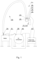
- Fig. 1 schematically shows one of embodiments of a system 1 for spraying a composition of adhesive, specifically a hot-melt adhesive onto glued surfaces according to the invention.
- the system in its most simplified shape comprises a heating device, specifically a melter 61 to heat hot melt adhesive, an air compressor 60, a power and control system 63 and a gun 10, 110.
- a heating device specifically a melter 61 to heat hot melt adhesive
- an air compressor 60 a power and control system 63 and a gun 10, 110.
- To the gun 10, 110 is fed the hot-melt adhesive at a temperature of 100°C in one embodiment, and at a temperature of 200°C or even 220°C in another embodiment, and in the preferred embodiment at a temperature of 180°C, connected by a connection hose 50 to the melter 61, equipped with a gear or pressure pump, and an air compressor 60.
- the power and control system 63 is connected to the gun 10, 110 by a wiring harness 30 terminated by an electrical connector 36 with a plug 31, as
- connection hose 50 in the embodiment shown in Fig. 1 is a hose without its own heating and has a pipe 53 with screw connectors 54, 55 through which the heated hot-melt adhesive flows, and an air pipe 56 with connectors 57, 58 through which compressed air flows at a pressure of 100 kPa in one embodiment, 1000 kPa in another, and 300 kPa in a preferred embodiment.
- the air fed to the gun is at an ambient temperature and is pressurized up to 1000 kPa.
- the ambient temperature can reach 5°C, 10°C, 20°C, 25°C and even more degrees Celsius.
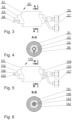
- connection hose Other embodiments of the connection hose are shown in Figs. 3, 4, 5, and 6 .
- Both the connection hose 50 shown in Fig. 3 and Fig. 4 and the connection hose 150 shown in Fig. 5 and Fig. 6 are multi-layered.
- the hose 50 in Fig. 3 and Fig. 4 has an inner diameter of 6 mm, 8 mm, 10 mm, 12 mm, 14 mm, or even more than 14 mm, which means that the most common inner diameter of the hose is between 6 mm and 14 mm.
- An outer protective layer 51 of the jacket is usually 14 mm, 16 mm, 18 mm, 20 mm or 44 mm.
- the protective layer 51 surrounds an insulating layer 52, in which the air pipe 56 and the pipe 53, through which the heated hot melt adhesive flows, and is positioned near the air pipe 56 and is in contact with it along the hose 50, along which the insulating layer 52 of the hose 50 is placed, so that the air pumped into the gun is heated spontaneously by the heated hot-melt adhesive.
- Common air pipe diameters are 8 mm, 10 mm, 12 mm, and their jacket thickness is 2 mm, 3 mm or 4 mm.
- connection hose 150 shown in Fig. 5 and Fig. 6 has an outer protective layer 151 which surrounds an insulating layer 152.
- the difference between the two hose embodiments is that an air pipe 153 with a connector 157 is fitted in a pipe 156 with a connector 155 through which the heated hot-melt adhesive flows, and separation of the pipes 153, 156 at both ends is ensured by splitters 159 placed at the end of the insulating layer of the hose 150.
- an inner diameter of the pipe which is an outer pipe, is larger than an outer diameter of the inner pipe, which has a diameter of 2 mm, 3 mm, 4 mm, or 5 mm.
- the air pipe 56, 153 and the pipe 53, 156 through which the heated hot-melt adhesive flows are made of teflon. Both the air pipe 56, 153 and the pipe 53, 156 through which the heated hot melt adhesive flows are adapted to operate at a temperature up to 260°C and at a pressure up to 1200 kPa or even up to 14000 kPa.
- the pipe through which the heated hot melt adhesive flows is placed inside the air pipe within a section of the connection hose where the insulating layer of the hose is fitted.
- Fig. 2 schematically represents one embodiment of the gun 10 with the connectors 54, 55, 57 and 58 of the connection hose 50.
- a more detailed design of the guns 10, 110 is shown in Fig. 7 and 8 .
- the gun 10 shown in Fig. 2 and Fig. 7 has a housing 11 in an interior of which, in a front part of the gun 10, a hot melt adhesive container 24 is fitted, which ensures that the temperature of hot melt adhesive leaving a nozzle of the gun is maintained at a desired and preset value without fear that the hot-melt adhesive will be cooled as it flows through through-holes in the housing of the gun 10.
- At least one heater 32 with a wire 39 and at least one temperature sensor 37 are fitted in walls of the gun 10 that surround the hot melt adhesive container 24 with a ferrule 13. The heater 32 is placed inside a recess 33, immediately by the nozzle so that adhesive leaving the gun has the same temperature as the gun heater.
- the temperature sensor 37 is placed in a recess 38, and both recesses 33, 38 are accessible in particular from a side of wall 12 separating the hot melt adhesive container 24 from an inner chamber of the gun 10 fitted mainly inside a grip part of the gun 10.
- the temperature sensor 37 is directly connected via a wire 35 to a temperature controller which controls the heater of hot melt adhesive placed in the melter to allow fast response of the adhesive heater controlled by the power and control system 63 to adhesive temperature fluctuations in a gun container, which also improves the temperature stability of adhesive leaving the gun.
- the button 40 is mounted pivotally in a joint 42 in the gun housing 11 and is leaned on a spring 44.
- the outlet 21 of the hot melt adhesive is connected to the hot melt adhesive container 24 by a channel 15, through which the hot melt adhesive flows into the outlet 21 of the hot-melt adhesive that is closed by the end of the needle 14.
- the pusher 43 with the needle retracts, which allows the hot-melt adhesive to flow out and be sprayed.
- the inner air line 26 is fitted with a cut-off valve 28, cutting off the flow of the compressed air that flows through the inner air line 26 upon the action of the button 40 on the valve 28 through the spring element 41.
- the above-mentioned inner air line 26 connects the air ferrule 29 of the gun 10 through a connector 27 to air ducts 25 connected to an outlet 23 of the compressed air.
- the compressed air outlet 23 in the embodiments of the invention shown in Fig. 2 and 7 are openings in a front wall 17 of a nozzle 20, shown in Fig. 11 , surrounding the hot-melt adhesive outlet 21.
- the gun 110 shown in Fig. 8 is similarly designed to the gun 10 in Fig. 7 and has a housing 111, inside of which there is a container 124 of the hot-melt adhesive fitted at the front of the gun 110 and an inner air pipe connecting an air connector 129 to air ducts 125 and a button 140.
- the hot-melt adhesive container 124 is much larger than the gun 10 container shown in Fig. 7 , which reduces temperature fluctuations of the hot-melt adhesive leaving an outlet 121 of the hot melt adhesive.
- the hot melt adhesive container 124 may have smaller dimensions than the gun 10 container shown in Fig. 7 , when the gun is intended for bonding small surfaces, which limits a demand for the adhesive. In such a case, the adhesive is quickly heated to a required temperature, for example after a downtime.
- heaters 132, 232 and temperature sensors 137 are located in walls of the gun 110, which surround the hot melt adhesive container 124 with a screw connector 113.
- the heater 132 with wires 139 is fitted in a recess 133
- the temperature sensors 137 with wires 135 are fitted in recesses 138 which are positioned in particular in a wall 112 separating the hot melt adhesive container 124 from an inner chamber of the gun 110 placed mainly in a grip part of the gun 110.
- the heater 232 is placed immediately by the nozzle 120 of the gun 110 and is fitted in a recess 233.
- Such arrangement of the heater ensures a proper temperature of the adhesive getting out through an opening or openings made in a front wall 117 of the nozzle 120. Openings in the front wall 117 of the nozzle 120 surrounding the hot melt adhesive outlet 121 or orifice serve as an outlet of the compressed air.
- Fig. 9 shows a cross-sectional view of a part of the housing 11, 111 of the gun shown in Fig. 2 , Fig. 7 , and Fig. 8 , at the point where it is connected by a threaded connection 22 to the nozzle selected from the nozzles 20, 120, shown in Figs. 10-13 .
- Fig. 9 shows in detail the connection of the adhesive container 24, 124 with the channel 15 through which the hot-melt adhesive flows into the outlet 21 closed by the end of the needle 14, and the connection of the air channels 25, 125 with inlet channels 225 and the air openings 23.
- the nozzle 20, 120 has a seal 18 at the side of the gun.
- the hot melt adhesive outlet 21, situated centrally in a conical protrusion 19 of the front wall 17,117, is surrounded by the air openings 23.
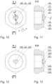
- Figs. 10-13 show various embodiments of nozzles screwed onto the threaded part of the gun 10, 110.
- Fig. 10 shows a front view of one embodiment of the nozzle 20, while Fig. 11 shows its cross-sectional view.
- the nozzle 20 with a body 16 comprises a hot-melt adhesive through-hole connecting the hot-melt adhesive outlet 21 to the hot melt adhesive container 24.
- the diameter of the opening for hot melt adhesive in the given embodiments is 0.8 mm, 1.0 mm, 1.2 mm, or even 1.5 mm.
- the nozzle 20 has a seal 18.
- the hot melt adhesive outlet 21, fitted centrally in a conical protrusion 19, is surrounded by the air openings 23 placed in the front wall 17 of the nozzle 20, moreover, in this embodiment, the outlet 21 is surrounded by twelve air openings 23 whose longitudinal symmetry axes are inclined at an angle ⁇ to a symmetry axis of the nozzle.
- at least one air opening 23 has a symmetry axis placed at a distance a from a plane passing through the longitudinal symmetry axis of the nozzle 20.
- the distance a may equal 1.0 mm, 1.5 mm, 2.0 mm, 2.5 mm, or even be greater than 3.0 mm.
- the hot melt adhesive outlet is placed centrally in a truncated cone shaped protuberance, and is surrounded by the air openings which are placed in the front wall of the nozzle and whose longitudinal symmetry axes lie in planes passing through the longitudinal symmetry axis of the nozzle.
- Fig. 12 shows a front view of yet another embodiment of the nozzle 120, which has six air openings 123 surrounding the hot melt adhesive outlet 121.
- Fig. 13 shows a cross-sectional view of another embodiment of the nozzle 120 with a nut-shaped body 116 ended with the front wall 117 comprising a conical protrusion 119 with a symmetry axis placed in the symmetry axis of the nozzle.
- the nozzle 120 On the gun side, the nozzle 120 has a seal 118.
- the hot melt adhesive outlet 121 is surrounded by the air openings 123 whose longitudinal axes are placed parallelly to the symmetry axis of the nozzle 120.
- the hot melt adhesive outlet 121 in this embodiment has a diameter equal to the diameter of the smaller base of the truncated cone but may also have a smaller diameter.
- the vertical angle of the protrusion 119 is 75°, in another 90°, then 105° and 120°.
- the nozzle has 6, 8, 10, 14, or more air openings.
- adhesive may be distributed into small particles with improved efficiency and sprayed onto surfaces to be bonded, which increases the possibility of bonding by applying the adhesive to one of the surfaces to be bonded together, and not as before, when the adhesive had to be applied mostly to both contacting surfaces to be bonded. Moreover, better adhesive breakdown not only results in better bonding quality but also results in limiting the adhesive consumption.
- the nozzle having the conical protrusion 19, 119, allows the adhesive to be sprayed from various distances from the surfaces to be bonded, which has not been possible with flat nozzles used so far. Common diameters of the nozzle air openings in the embodiments described above are 0.3 mm, 0.4 mm, 0.6 mm, or even 0.8 mm.
- Fig. 14 schematically shows another embodiment of the system 101 for spraying the hot-melt adhesive on surfaces to be bonded compliant with the invention, which is similar to the system 1 for spraying the hot-melt adhesive, shown in Fig. 1 .
- the system 101 shown in Fig. 14 compared to the system 1 in Fig. 1 , additionally has a heater 65 of air pressed to the hose 50.
- the remaining devices such as the melter 61 for heating the hot-melt adhesive, the air compressor 60, the power and control system 63, and the gun 10 or 110, connected to the melter 61 by the pipe 53 with the connectors 54, 55, through which the heated hot-melt adhesive flows, and connected to the air compressor 60 by the air pipe 56 with the connectors 57, 58, perform similar functions as in the system in Fig. 1 .
- the air compressed by the air compressor 60 is heated by the air heater 65 connected to the air compressor 60 by an external air hose 64.
- the air heater 65 is an accessory.
- connection hose 50 which houses the air pipe 56 and the pipe 53, through which the heated hot melt adhesive flows, is suspended by a holder 90 of a system 70 for suspending flexible elements.
- the holder 90 is movable along an arm 86, which is mounted rotatably around a vertical axis and vertically movable along a stand 81 of a system 80 for suspending the connection hose 50.
- the vertical position of the arm 86 on the stand 81 is determined by clamps 85 with a setting screw 79, whereby in seats of clamps 88 a spindle is located, which keeps the arm in a horizontal position. Additionally, the horizontal position of the arm 86 is maintained by a tensioner 87.
- the stand 81 of this system is seated on a base 82 with a weight 83.
- the stand 81 is held in the vertical position by a stay 84.
- a spring 91 of the holder 90 is loosely wound on the connection hose 50, which, by means of hangers 92, is suspended to a mobile system 93 of the holder 90, in particular to a housing 94 of an elongated bearing 98 movable along the arm 86 and slide-fitted on the arm 86.
- the hangers 92 in this embodiment are bars or pipes.
- the bearing 98 in this embodiment is loosely fitted on the arm 86, which allows the holder 90 of the mobile system 93 to move along the arm 86, in particular with a circular cross-section.
- the bearing has a length exceeding an inner diameter of the bearing 98, specifically, the length is three times the inner diameter of the bearing 98. In one embodiment, the bearing length is 80.0 mm and, in another, the bearing length is 100.00 mm or even more.
- the bearing 98 has numerous rows of balls preferably evenly spaced at a predetermined distance around the circumference of the bearing interior, which reduces frictional resistance when the bearing is moved along the arm, preferably of circular cross-section.
- the bearing 98 is fitted inside a tube-shaped housing 94 and is locked in the housing by a bolt 97 with a lock nut 96.
- snap-in holders 95 are attached to the housing 94, to which upper ends of the hangers 92 are attached, the lower ends of which are attached to the spring 91 of the holder 90.
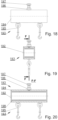
- Figs. 18, 19, 20 show in detail another embodiment of a mobile system 193 with a bearing 198 and its housing 194.
- the bearing 198 shown in Fig. 18 is loosely fitted on one of booms 330, 430, shown in one of Figs. 23, 24 , which allow movement of the mobile system 93, 193 along the boom 330, 430, in particular with a rectangular cross-section.
- the bearing 198 has numerous rows of balls touching an external surface of the boom 330, 430, shown as examples in Figs.
- the bearing 198 is fitted inside a rectangular-shaped housing 194 and is locked in the housing by fixing elements 192 and a bolt 197 with a lock nut 196.
- holders or handles 195 with slings are attached to the housing 194. The slings are fixed to the spring 91, 391, 491, according to the solutions shown in Figs. 14 , 18 and 19 .
- Fig. 21 represents schematically another embodiment of a system 201 for spraying hot-melt adhesive on surfaces to be bonded according to the invention.
- the system 201 like the systems 1, 101 in Fig. 1 and Fig. 14 , respectively, comprises the gun 10, 110, 210 in various versions as previously described, a heating device, specifically a melter 261 for heating hot-melt adhesive, a compressed air supply system 260, specifically an air compressor, and the power and control system 63, 263 integrated within the melter 261.
- the gun 10, 110, 210 is provided with the heater 32, the sensor 37, the hot melt adhesive container 24, into the outlet 21 of which, closed by the needle, is pumped hot-melt adhesive of a temperature between 100°C and 220°C through the tube 56 of the connection hose 50, 150 shown in Fig. 3 or 5 with a melter container 264 of the melter 261 for hot-melt adhesive, equipped with an adhesive heater 265 and a gear pump 267 driven by a motor 268 or a pressure pump.
- the pressure pump is driven by compressed air with an output determined by a pressure regulator interacting with the power and control system 63, 263.
- the gun 10, 110, 210 is connected by the air tube 53 through a valve 28, shown in Fig.
- the compressed air is heated by an air heater 269 shown in Fig. 22, fitted especially in the compressed air supply system 260, operating as an independent unit, or which is arranged in particular in the compressed air supply system 260, powered and controlled by the power and control system 63, 263.
- the gun is connected to a power and control system 63, 263 to which, in particular, data is directly transmitted from the sensor 37 placed near the outlet 21 of the nozzle 20 of the gun 10, 110, 210, that can respond to changes of temperature and pressure in the hot melt adhesive container 24 of the gun 10, 110, 210.
- a power and control system 63, 263 to which, in particular, data is directly transmitted from the sensor 37 placed near the outlet 21 of the nozzle 20 of the gun 10, 110, 210, that can respond to changes of temperature and pressure in the hot melt adhesive container 24 of the gun 10, 110, 210.
- Fig. 23 represents schematically one of the embodiments of a system 370 for suspending flexible elements, especially long flexible elements, in particular hoses.
- a flexible element within the meaning of the invention is an element which has no permanent form and bends under its own weight.
- a long flexible element is an element whose length is several times greater than the largest transverse dimension, for example, more than ten-fold greater.
- the system 370 for suspending flexible elements comprises a holder 390 for holding a flexible element 350, for example a rope or a hose, which is attached to the mobile system 93, 193 movable along the boom 330 which is attached to a stand 310, for example a pole 381, by means of an adjusting system 320 allowing for change of the distance of the boom 330 from the ground.
- the holder 390 comprises a spring 391 wound and movable on a flexible element 350, which means that an inner diameter of the spring 391 is larger than an outer diameter of the flexible element 350 and the flexible element can move relative to the spring.
- the spring 391 according to the example from Fig.
- the adjusting system is performed by the fixture of the boom 330, not shown in the drawing, to any movable structure or stationary element, for example a wall.
- clamps 388 seated on the pole 381 of the stand 310 and a mandrel or pin 373 to which the boom 330 of the mobile system 93, 193 is attached.
- the clamps 388 for example, the upper clamp and the lower clamp, are fixed adjustable along the pole 381 of the stand 310, and at least one clamp, preferably the lower clamp, is locked relative to the pole 381 by a screw 379 at a selected distance from the ground, which prevents the position of the boom 330 from changing the selected distance from the ground.
- clamps may be replaced by plates that are attached to the moveable structure or wall and that have seats for the mandrel, such as the seats of the clamps 388.
- the clamps 388 have seats 385 set off from the post 381 in which ends of the mandrel 373, which may move vertically, are pivotally seated around its vertical axis, which is performed by means of at least one screw 379 screwed into a threaded through-hole made in at least one clamp.
- the boom 330 for example a rod or pipe 386 of any cross-section, is permanently attached to the mandrel 373.
- the post has a base 380 that may be permanently fixed to the ground or to a movable element, such as a movable pallet or a cart that moves on the ground.
- Fig. 24 shows another embodiment according to the invention of a system 470 for suspending very long flexible elements 450, e.g. hoses 451, especially connection hoses, with a connector 453 and a valve 452. Due to its build, the system 470 enables longer distance transport of the hot melt adhesive.
- the system 470 for suspending long flexible elements comprises holders 490, similar to the holders 390 of the system 370, for holding a long flexible element 450 in several points, each of which is attached to the mobile system 93, 193 movable along a boom 430, which is attached to a stand 410 by means of an adjusting system 420.
- Each holder 490 comprises a spring 491 wound and movable on the flexible element 450. According to the embodiment shown in Fig.
- each spring 491 is suspended to the mobile system 93, 193 by at least one suspending element 492.
- the adjusting system 420 shown in Fig. 24 is similar to the adjusting system 320 shown in Fig. 23 and includes at least two clamps 488 seated on a pole 481 of the stand 410 and a mandrel 473 to which the boom 430 of the mobile system 93, 193 is attached, similarly to the embodiment from Fig. 23 .
- the clamps 488 are connected by a strut 472, that prevents the mandrel 473 from falling out of seats 485 of the clamps 488, and at least one of the clamps is locked relative to the pole 481 with a base 480 by a setting screw 479 screwed into a threaded through hole until it touches the pole 481.
- the boom 430 for example a rod or pipe 486 of round or rectangular cross-section, is permanently attached to the mandrel 473.
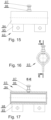
- Figs. 25, 26 and 27 show the clamp 388, 488, that is attached to a stand's pole of one of the adjusting systems 320, 420 described above.
- Fig. 25 shows a longitudinal section of the clamp 388, 488
- Fig. 26 shows a top view of the clamp shown in Fig. 25
- Fig. 27 shows a side view of the clamp shown in Fig. 25 .
- the clamp 388, 488 has a shape of a rectangular plate 541 with a through hole 542 whose diameter D corresponds to an outer diameter of the pole, which is seated on the pole of the systems previously described. The diameter D is selected so that the clamp may be moved along the pole on which it is mounted.
- the plate 541 has a cylindrical recess 543 with a diameter d, which forms a seat 389, 489 for seating the mandrel 383, 483, shown in Fig. 28 , of the systems previously described.
- the clamp 388, 488 may be an upper clamp, in the seat or socket of which the top pivot of the mandrel 373, 473 is pivotally seated, and may be a lower clamp, in the socket of which the bottom pivot of the mandrel 373, 473 is pivotally seated, which in this embodiment is formed from a rod 551 with cylindrical-shaped sections 552 at its ends whose diameter d corresponds to the diameter d of the recess 543.
- the plate has a threaded hole 544 from its front side, into which a screw is screwed to lock the clamp relative to the pole on which the clamp is mounted.
- plates similar to the plate 541 shown in Figs. 25, 26, and 27 comprising sockets only, are permanently fixed to the movable structure or the stationary element at such a distance that the mandrel to which the boom is attached has the ability to rotate around its own vertical axis.
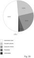
- the adhesive used for gluing elements may be bonded with any hot melt adhesive. Composition of the adhesive has been shown in one of embodiments in Fig. 29 .
- the hot-melt adhesive composition is suitable for gluing using the system proposed by the invention or according to the invention, in particular the hot-melt adhesive containing by weight not more than 55.0% of hydrocarbon resin, not more than 6.0% of polybutene, not more than 1.5% of antioxidant, not more than 27.0% of copolymer mixture, and not more than 27.0% of polyolefin polymer.
- the hot-melt adhesive comprises 50.05% and, in another, 55.00% of hydrocarbon resin, in general between 50.05% and 55.00% of hydrocarbon resin, 5.05% and, in another, 6.00% of polybutene, in general between 5.05% and 6.00% of polybutene, 1.05% and, in another, 1.50% of antioxidants, in general between 1.05% and 1.50% of antioxidants, 21.50%, and, in another, 27.00% of polyolefin polymer, in general between 21.50% and 27.00% of polyolefin polymer, and copolymer mixture in an amount complementary to 100.00% of the components, i.e., a copolymer mixture of 22.35%, and, in another, 10.5%, in general between 10.5% and 22.35% of copolymer mixture.
- hot melt adhesive comprises 51.0% of hydrocarbon resin, 5.5% of polybutene, 1.2% of antioxidants, 16.8% of copolymer mixture and 25.5% of polyolefin polymer by weight.
- the hot melt adhesive composition comprises 51.0% of hydrocarbon resin, 5.5% of polybutene, 1.2% of antioxidants, 16.8% of copolymer mixture and 25.5% of polyolefin polymer by weight.
- an antioxidant known in the state of the art may be one of the polymer stabilizing products that is produced by companies, for example BASF, under Irganox trade name, and a copolymer mixture may be a polyolefin mixture.
- the adhesive used for bonding based on the system proposed by the invention should have a viscosity of 2500 mPa*s, and, in another embodiment, of 2800 mPa*s, and in general between 2500 mPa*s and 2800 mPa*s, at a temperature between 120°C and 200°C, and a density of 0.9 kg/dcm 3 , and, in another embodiment, of 1.4 kg/dcm 3 , and in general between 0.95 kg/dcm 3 to 1.4 kg/dcm 3 , preferably between 0.9 kg/dcm 3 and 0.95 kg/dcm 3 .
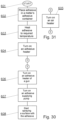
- Fig. 30 and Fig. 31 show a block diagram of one of the methods of preparing an adhesive ready for spraying a hot-melt adhesive on surfaces to be bonded, in particular surfaces of furniture elements and various materials, especially in the production of upholstered furniture.
- the hot-melt adhesive is placed in the melter's hot-melt adhesive container in step 602, which is then heated to the desired temperature in step 603.
- an air compressor is started, which pumps air at a pressure up to 1200 kPa, and in step 606 the adhesive heater in the gun is turned on, wherefore in step 607 an adhesive delivery pump is turned on, supplying hot melt adhesive with a viscosity of 2500 mPa*s, in one case, and 2800 mPa*s, in another, in general between 2500 mPa*s and 2800 mPa*s, and with a density of 0,8 kg/dcm 3 , in one case, and 1,4 kg/dcm 3 , in another, in general between 0,8 kg/dcm 3 and 1,4 kg/dcm 3 , preferably between 0,9 kg/dcm 3 and 0,95 kg/dcm 3 , and heated to a temperature of 120°C, in one case, and 200°C, in another, in general between 120°C and 200°C, to the gun ferrule through a pipe placed in the hose in its insulating layer with a
Landscapes
- Chemical & Material Sciences (AREA)
- Organic Chemistry (AREA)
- Analytical Chemistry (AREA)
- Nozzles (AREA)
- Adhesives Or Adhesive Processes (AREA)
- Coating Apparatus (AREA)
Claims (14)
- System (1, 101, 201) zum Sprühen eines Heißschmelzklebstoffs auf Klebeflächen, umfassendeine Schmelzvorrichtung (61) zum Erhitzen des Heißschmelzklebstoffs,einen Luftkompressor (60, 260),ein Leistungs- und Steuerungssystem (63, 263) undeine Pistole (10, 110), die eine Düse (20) mit einem Heißschmelzklebstoffauslass oder einer -Öffnung (21) und einem Druckluftauslass (23) aufweist und mit der Schmelzvorrichtung (61, 261) durch eine Leitung (53) mit Schraubverbindern (54, 55) verbunden ist, durch die ein Heißschmelzklebstoff, der erhitzt wird, fließt, und mit dem Luftkompressor (60, 260) durch eine Luftleitung (56) mit Schraubverbindern (57, 58) verbunden ist, durch die unter Druck stehende Druckluft fließt, wobeidie Leitung (53), durch die der Heißschmelzklebstoff mit einer Viskosität zwischen 2500 mPa*s und 7000 mPa*s und einer Temperatur zwischen 120 °C und 200 °C und einer Dichte zwischen 0,8 kg/dcm3 und 1,4 kg/dcm3 fließt, und die Luftleitung (56) in einer Isolierschicht eines Verbindungsschlauchs (50) angebracht sind, und wobei der Durchsatz der Leitung (53), durch die der Heißschmelzklebstoff, der erhitzt wird, fließt, zwischen 0,5 kg/h und 1,5 kg/h liegt, während die Luftleitung (56) einen Durchsatz zwischen 0,1 m3/min und 0,6 m3/min aufweist,dadurch gekennzeichnet, dasssich mindestens eine Heizung (32) und mindestens ein Temperatursensor (37) innerhalb der Wände der Pistole (10), die mit einem Heißschmelzklebstoffbehälter (24) in Kontakt stehen, befinden und die Heizung (32) und der Temperatursensor (37) in Aussparungen (33 beziehungsweise 38) angebracht sind, die in einer Wand (12) angeordnet sind, die den Heißschmelzklebstoffbehälter (24) von einer Innenkammer der Pistole (10) trennt.
- System (1, 101, 201) zum Sprühen eines Heißschmelzklebstoffs nach Anspruch 1, dadurch gekennzeichnet, dass der Verbindungsschlauch (50) mittels eines Systems (70, 370, 470) zum Aufhängen flexibler Elemente aufgehängt ist, das eine Halterung (90, 390, 490) zum Halten des Verbindungsschlauchs (50, 150) umfasst, wobei die Halterung (90, 390, 490) an einem beweglichen System (93, 193) befestigt ist, das entlang eines Auslegers (330, 430) bewegbar ist, der mittels eines Verstellsystems (320, 420) an einem Ständer (310, 410) befestigt ist, das eine Baugruppe des Auslegers (330, 430) ist, die an einer beweglichen Konstruktion oder einem festen Element befestigt ist.
- System (1, 101) zum Sprühen eines Heißschmelzklebstoffs nach Anspruch 2, dadurch gekennzeichnet, dass die Halterung (90, 390, 490) mindestens eine Feder (91, 391, 491) umfasst, die lose auf den Verbindungsschlauch (50, 150) gewickelt ist, der mittels Aufhängern (92, 392, 492) an mindestens einem beweglichen System (93, 193) aufgehängt ist, wodurch die einen Enden der Aufhänger (92, 392, 492) auf einer Seite an dem beweglichen System (93, 193) befestigt sind und die anderen Enden der Aufhänger (92, 392, 492) im Bereich der Enden der Feder (91, 391, 491) oder einer Federmitte angebracht sind.
- System (1, 101, 201) zum Sprühen eines Heißschmelzklebstoffs nach Anspruch 1 oder 2 oder 3, dadurch gekennzeichnet, dass das Verstellsystem (320, 420) den Ständer (310, 410) mit einer Stange (81, 381, 481) und mindestens zwei an der Stange (381, 481) des Ständers (310, 410) sitzende Klemmen (88, 388, 488) und eine Spindel (373, 473) umfasst, mit der der Ausleger (330, 430) verbunden ist und neben der die entlang der Stange (381, 481) des Ständers (310, 410) mittels einer Schraube (79, 379, 479) fixierten Klemmen (88, 388, 488) Aufnahmen (389, 489) aufweisen, in denen die Spindel (373, 473) mit ihren Enden drehbar um ihre vertikale Achse sitzt.
- System (1, 101, 201) zum Sprühen eines Heißschmelzklebstoffs nach Anspruch 1 oder 2 oder 3 oder 4, dadurch gekennzeichnet, dass das bewegliche System (93, 193) ein längliches Lager (98, 198) mit einem kreisförmigen oder rechteckigen Innenquerschnitt mit mehreren Reihen von Kugeln umfasst, die gleichmäßig und vorzugsweise in einem vorbestimmten Abstand um einen Umfang des Lagerinneren herum beabstandet sind und mit einer Außenfläche des Auslegers (330, 430) in Kontakt stehen, und das lose auf dem Ausleger (330, 430) angebracht ist und das in einem Gehäuse (94, 194) entweder mit Schnapphalterungen (95) oder Riemen (195) angeordnet ist.
- System (1, 101, 201) zum Sprühen eines Heißschmelzklebstoffs nach Anspruch 1 oder 2 oder 3 oder 4 oder 5, dadurch gekennzeichnet, dass die Leitung (53), durch die der erhitzte Heißschmelzklebstoff fließt, benachbart zu der Luftleitung (56) angeordnet ist und damit innerhalb des Abschnitts des Verbindungsschlauchs (50), in dem eine Isolierschicht (52) des Verbindungsschlauchs (50) angebracht ist, in Kontakt steht.
- System (1, 101, 201) zum Sprühen eines Heißschmelzklebstoffs nach Anspruch 1 oder 2 oder 3 oder 4 oder 5, dadurch gekennzeichnet, dass die Luftleitung (153) innerhalb der Leitung (156), durch die der erhitzte Heißschmelzklebstoff fließt, an dem Abschnitt des Verbindungsschlauchs (150), in dem eine Isolierschicht (152) des Verbindungsschlauchs (150) angebracht ist, angebracht ist.
- System (1, 101, 201) zum Sprühen eines Heißschmelzklebstoffs nach Anspruch 1 oder 2 oder 3 oder 4 oder 5, dadurch gekennzeichnet, dass die Leitung, durch die der erhitzte Heißschmelzklebstoff fließt, innerhalb der Luftleitung in dem Abschnitt des Verbindungsschlauchs (150), in dem die Isolierschicht (152) des Verbindungsschlauchs (150) angebracht ist, angebracht ist.
- System (1, 101, 201) zum Sprühen eines Heißschmelzklebstoffs nach Anspruch 1 oder 2 oder 3 oder 4 oder 5, dadurch gekennzeichnet, dass die Leitung (53, 156), durch die der erhitzte Heißschmelzklebstoff fließt, durch den Verbinder (55, 155) mit einer Hülse (13) mit einem Durchgangsloch verbunden ist, das einen Auslass oder eine Öffnung der Leitung (53, 156) mit dem Heißschmelzklebstoffbehälter (24) verbindet, der in einem vorderen Teil der Pistole (10) angeordnet ist.
- System (1, 101, 201) zum Sprühen eines Heißschmelzklebstoffs nach einem der vorhergehenden Ansprüche, dadurch gekennzeichnet, dass eine Heizung (232) in der unmittelbaren Nähe einer Düse (120) der Pistole (110) angebracht ist und der Temperatursensor (37) direkt mit der Temperatursteuerung des Leistungs- und Steuersystems (63, 263) verbunden ist, das den Betrieb der in der Schmelzvorrichtung angeordneten Klebstoffheizung steuert, mit dem Ziel, eine schnelle Reaktion einer durch das Leistungs- und Steuersystem (63, 263) gesteuerten Klebstoffheizung (265) auf Klebstofftemperaturschwankungen in dem Pistolenbehälter zu ermöglichen, und dass in der Innenkammer der Pistole (10, 110) ein Schalter (40, 140) angeordnet ist, der schwenkbar an einem Pistolengehäuse (11, 111) montiert ist und teilweise über das Gehäuse (11, 111) hinausragt, an dem ein Drücker (43) mit einer Nadel befestigt ist, dessen Ende bis zu dem Heißschmelzklebstoffauslass oder zu der -Öffnung (21) reicht, um ein Ausfließen des Klebstoffs zu verhindern, wenn die Pistole (10, 110) nicht in Gebrauch ist, und dass sich innerhalb der Innenkammer der Pistole (10) ein inneres Luftkabel (26) mit einem Ventil (28) befindet, das den Druckluftstrom durch das innere Luftkabel (26) unterbricht, wenn der Schalter (40) auf das Ventil (28) einwirkt, während das innere Luftkabel (26) eine Lufthülse (29) der Pistole (10) mit Luftkanälen (25) verbindet, die mit dem Druckluftauslass verbunden sind.
- System (1, 101, 201) zum Sprühen eines Heißschmelzklebstoffs nach einem der vorhergehenden Ansprüche, dadurch gekennzeichnet, dass der Druckluftauslass Luftöffnungen (23, 123) in einer Vorderwand (17) der Düse (20, 120) sind, die einen Heißschmelzklebstoffauslass (21, 121) umgeben, der zentral in der Düse (20, 120) und in einer Vorderwand der Düse (20, 120) angeordnet ist, und dass der Heißschmelzklebstoffauslass (21) eine kegelstumpfförmige Form aufweist, während die Luftöffnungen (23) eine Längssymmetrieachse aufweisen, die in einem Winkel (α) zu einer Mittelachse der Düse geneigt ist, und mindestens eine Luftöffnung (23) die Symmetrieachse innerhalb einer Ebene aufweist, die in einem Abstand (a) von einer Ebene angeordnet ist, die durch die Längssymmetrieachse der Düse (20) verläuft.
- System (1, 101, 201) zum Sprühen eines Heißschmelzklebstoffs nach einem der vorhergehenden Ansprüche, dadurch gekennzeichnet, dass das System (1, 101, 201) zum Sprühen des Heißschmelzklebstoffs geeignet ist, der nicht mehr als 1,5 Gewichts-% Antioxidantien umfasst und ferner nicht mehr als 55,0 Gewichts-% Kohlenwasserstoffharz, nicht mehr als 6,0 Gewichts-% Polybuten, nicht mehr als 27,0 Gewichts-% Copolymergemisch und nicht mehr als 27,0 Gewichts-% Polyolefinpolymer umfasst.
- System (1, 101, 201) zum Sprühen eines Heißschmelzklebstoffs nach Anspruch 12, dadurch gekennzeichnet, dass das System (1, 101, 201) zum Sprühen des Heißschmelzklebstoffs geeignet ist, der 1,05 Gewichts-% Antioxidantien umfasst und ferner 48,6 Gewichts-% Kohlenwasserstoffharz, 5,05 Gewichts-% Polybuten, zwischen 22,8 Gewichts-% und 23,0 Gewichts-% Polyolefinpolymer, vorzugsweise 22,9 %, und ein Copolymergemisch in einer zu 100,0 Gewichts-% ergänzenden Menge, vorzugsweise 22,4 %, umfasst.
- Verfahren zum Sprühen eines Heißschmelzklebstoffs auf Klebeflächen unter Verwendung eines Systems zum Sprühen eines Heißschmelzklebstoffs auf Klebeflächen nach einem der Ansprüche 2 bis 13, wobei der Heißschmelzklebstoffauslass (21) und der Druckluftauslass (23) auf zu verklebende Flächen gerichtet sind, wobei zu dem Einlassanschluss der Pistole durch die Leitung (53), die in dem Verbindungsschlauch (50) innerhalb seiner Isolierschicht angebracht ist, mit einem Durchsatz zwischen 0,5 kg/h und 1,5 kg/h unter einem Druck von 1200 kPa bis 4200 kPa ein Heißschmelzklebstoff mit einer Viskosität im Bereich von 2500 mPa*s bis 2800 mPa*s und einer Dichte im Bereich von 0,8 kg/dcm3 bis 1,4 kg/dcm3, vorzugsweise von 0,9 kg/dcm3 bis 0,95 kg/dcm3, der auf eine Temperatur zwischen 120 °C und 200 °C erhitzt ist, zugeführt wird, und durch die Luftleitung (56) mit einem Durchsatz von 0,1 m3/min bis 0,6 m3/min, das in dem Verbindungsschlauch (50) in seiner Isolierschicht im Bereich der Klebstoffzufuhrleitung angeordnet ist, Luft mit einem Druck von 100 kPa bis 1000 kPa zu einer Lufthülse der Pistole zugeführt wird.
Applications Claiming Priority (3)
| Application Number | Priority Date | Filing Date | Title |
|---|---|---|---|
| PL433672A PL241147B1 (pl) | 2020-04-24 | 2020-04-24 | System do natryskiwania kleju termotopliwego na powierzchnie klejone i sposób natryskiwania kleju termotopliwego na powierzchnie klejone |
| PL433674A PL240368B1 (pl) | 2020-04-24 | 2020-04-24 | System do podwieszania elementów giętkich |
| PL433673A PL241148B1 (pl) | 2020-04-24 | 2020-04-24 | Kompozycja kleju termotopliwego do natryskiwania na powierzchnie klejone, sposób natryskiwania kleju termotopliwego na powierzchnie klejone i system do natryskiwania kleju termotopliwego na powierzchnie klejone |
Publications (3)
| Publication Number | Publication Date |
|---|---|
| EP3900839A1 EP3900839A1 (de) | 2021-10-27 |
| EP3900839C0 EP3900839C0 (de) | 2025-01-29 |
| EP3900839B1 true EP3900839B1 (de) | 2025-01-29 |
Family
ID=75870353
Family Applications (1)
| Application Number | Title | Priority Date | Filing Date |
|---|---|---|---|
| EP21170325.1A Active EP3900839B1 (de) | 2020-04-24 | 2021-04-23 | System und verfahren zum sprühen von heissschmelzklebstoff auf klebeflächen und heissschmelzklebstoffzusammensetzung |
Country Status (4)
| Country | Link |
|---|---|
| US (1) | US11904342B2 (de) |
| EP (1) | EP3900839B1 (de) |
| ES (1) | ES3017563T3 (de) |
| PL (1) | PL3900839T3 (de) |
Citations (1)
| Publication number | Priority date | Publication date | Assignee | Title |
|---|---|---|---|---|
| CN1068952C (zh) * | 1998-12-25 | 2001-07-25 | 中国科学技术大学 | 光交联聚烯烃绝缘电缆的生产方法及其光交联设备 |
Family Cites Families (12)
| Publication number | Priority date | Publication date | Assignee | Title |
|---|---|---|---|---|
| US4632314A (en) | 1982-10-22 | 1986-12-30 | Nordson Corporation | Adhesive foam generating nozzle |
| DE3543469A1 (de) * | 1985-12-09 | 1987-06-11 | Henning J Claassen | Spruehkopf zum verspruehen eines thermoplastischen kunststoffes, insbesondere eines schmelzklebstoffes |
| US5171613A (en) * | 1990-09-21 | 1992-12-15 | Union Carbide Chemicals & Plastics Technology Corporation | Apparatus and methods for application of coatings with supercritical fluids as diluents by spraying from an orifice |
| DE29803637U1 (de) * | 1998-03-03 | 1999-07-15 | KUKA Schweissanlagen GmbH, 86165 Augsburg | Leitungsführung für einen mehrachsigen Industrieroboter |
| PL64959Y1 (pl) | 2008-02-14 | 2010-05-31 | Mirosław Tadla | Pistolet natryskowy |
| US7942350B2 (en) * | 2008-09-16 | 2011-05-17 | Shoap Stephen D | Method and system for fluid transmission along significant distances |
| US20180221897A1 (en) * | 2011-07-20 | 2018-08-09 | Sealanttech | Systems and Methods for Portable Multi-Component Mixing of Materials for Spray Application of Same |
| US9739399B1 (en) * | 2014-03-04 | 2017-08-22 | Robert D. Dundas | Hose holder system and related methods |
| CN107922697B (zh) | 2015-09-14 | 2021-07-13 | Sika技术股份公司 | 具有低再活化温度和高耐热性的聚烯烃热熔粘合剂及其用于真空深拉层合的用途 |
| CN206746940U (zh) | 2017-04-19 | 2017-12-15 | 福建省精泰设备制造有限公司 | 一种热熔胶喷枪 |
| CN209020688U (zh) | 2018-09-13 | 2019-06-25 | 恩龙实业(嘉兴)有限公司 | 一种热熔胶机 |
| DE102019130112A1 (de) * | 2019-11-07 | 2021-05-12 | Broetje-Automation Gmbh | Zerstäubereinheit |
-
2021
- 2021-04-23 PL PL21170325.1T patent/PL3900839T3/pl unknown
- 2021-04-23 EP EP21170325.1A patent/EP3900839B1/de active Active
- 2021-04-23 ES ES21170325T patent/ES3017563T3/es active Active
- 2021-04-24 US US17/239,579 patent/US11904342B2/en active Active
Patent Citations (1)
| Publication number | Priority date | Publication date | Assignee | Title |
|---|---|---|---|---|
| CN1068952C (zh) * | 1998-12-25 | 2001-07-25 | 中国科学技术大学 | 光交联聚烯烃绝缘电缆的生产方法及其光交联设备 |
Also Published As
| Publication number | Publication date |
|---|---|
| EP3900839C0 (de) | 2025-01-29 |
| US20210339273A1 (en) | 2021-11-04 |
| PL3900839T3 (pl) | 2025-03-17 |
| ES3017563T3 (en) | 2025-05-13 |
| EP3900839A1 (de) | 2021-10-27 |
| US11904342B2 (en) | 2024-02-20 |
Similar Documents
| Publication | Publication Date | Title |
|---|---|---|
| US4785996A (en) | Adhesive spray gun and nozzle attachment | |
| US6705537B2 (en) | Orbital applicator tool with self-centering dispersing head | |
| AU677232B2 (en) | A nozzle for use with an adhesive dispenser and method of depositing adhesive fibre onto a substrate | |
| US6691932B1 (en) | Orbital applicator tool with static mixer tip seal valve | |
| US20200122189A1 (en) | System, method, and apparatus for hot melt adhesive application | |
| AU620920B2 (en) | Nozzle attachment for an adhesive spray gun | |
| US5700322A (en) | Continuous hot melt adhesive applicator | |
| EP0438478A1 (de) | Verfahren und vorrichtung zur verabreichung von tropfen von thermoplastischen bindemitteln | |
| US8251261B2 (en) | Liquid delivery apparatus | |
| US11873206B2 (en) | Manifold and fluid dispensing systems | |
| US6168049B1 (en) | Hot melt adhesive applicator with centrally located filter | |
| EP3900839B1 (de) | System und verfahren zum sprühen von heissschmelzklebstoff auf klebeflächen und heissschmelzklebstoffzusammensetzung | |
| EP0020396B1 (de) | Verbesserungen an metallspritzvorrichtungen | |
| JPH06114299A (ja) | 火炎吹付け被覆装置 | |
| NZ536651A (en) | Spray-drying device and feed means for this spray-drying device | |
| CN118084361B (zh) | 一种多角度倾斜防火玻璃注胶成型装置及其使用方法 | |
| PL241147B1 (pl) | System do natryskiwania kleju termotopliwego na powierzchnie klejone i sposób natryskiwania kleju termotopliwego na powierzchnie klejone | |
| PL241148B1 (pl) | Kompozycja kleju termotopliwego do natryskiwania na powierzchnie klejone, sposób natryskiwania kleju termotopliwego na powierzchnie klejone i system do natryskiwania kleju termotopliwego na powierzchnie klejone | |
| US2551078A (en) | Paraffin sprayer | |
| CA2219264C (en) | Weight-supported adjustable mixing and dispensing gun for two chemically reactive materials | |
| MXPA00007059A (es) | Bloque de mezclado para mezclar sistemas de recubrimiento de material reactivo multicomponente y un aparato que lo utiliza. | |
| BR112021014388A2 (pt) | Dispositivo para fornecimento de adesivo | |
| GB2322817A (en) | Coating holes in threaded articles | |
| KR101763555B1 (ko) | 아크 용사용 와이어 송급 장치 | |
| US7740150B2 (en) | Holster for hot melt dispensing handgun |
Legal Events
| Date | Code | Title | Description |
|---|---|---|---|
| STAA | Information on the status of an ep patent application or granted ep patent |
Free format text: STATUS: UNKNOWN |
|
| PUAI | Public reference made under article 153(3) epc to a published international application that has entered the european phase |
Free format text: ORIGINAL CODE: 0009012 |
|
| STAA | Information on the status of an ep patent application or granted ep patent |
Free format text: STATUS: THE APPLICATION HAS BEEN PUBLISHED |
|
| AK | Designated contracting states |
Kind code of ref document: A1 Designated state(s): AL AT BE BG CH CY CZ DE DK EE ES FI FR GB GR HR HU IE IS IT LI LT LU LV MC MK MT NL NO PL PT RO RS SE SI SK SM TR |
|
| B565 | Issuance of search results under rule 164(2) epc |
Effective date: 20210929 |
|
| STAA | Information on the status of an ep patent application or granted ep patent |
Free format text: STATUS: REQUEST FOR EXAMINATION WAS MADE |
|
| 17P | Request for examination filed |
Effective date: 20211202 |
|
| RBV | Designated contracting states (corrected) |
Designated state(s): AL AT BE BG CH CY CZ DE DK EE ES FI FR GB GR HR HU IE IS IT LI LT LU LV MC MK MT NL NO PL PT RO RS SE SI SK SM TR |
|
| STAA | Information on the status of an ep patent application or granted ep patent |
Free format text: STATUS: EXAMINATION IS IN PROGRESS |
|
| 17Q | First examination report despatched |
Effective date: 20221201 |
|
| GRAP | Despatch of communication of intention to grant a patent |
Free format text: ORIGINAL CODE: EPIDOSNIGR1 |
|
| STAA | Information on the status of an ep patent application or granted ep patent |
Free format text: STATUS: GRANT OF PATENT IS INTENDED |
|
| GRAJ | Information related to disapproval of communication of intention to grant by the applicant or resumption of examination proceedings by the epo deleted |
Free format text: ORIGINAL CODE: EPIDOSDIGR1 |
|
| INTG | Intention to grant announced |
Effective date: 20241023 |
|
| RAP3 | Party data changed (applicant data changed or rights of an application transferred) |
Owner name: ARCIN SPOLKA Z OGRANICZONA ODPOWIEDZIALNOSCIA |
|
| STAA | Information on the status of an ep patent application or granted ep patent |
Free format text: STATUS: EXAMINATION IS IN PROGRESS |
|
| GRAS | Grant fee paid |
Free format text: ORIGINAL CODE: EPIDOSNIGR3 |
|
| STAA | Information on the status of an ep patent application or granted ep patent |
Free format text: STATUS: GRANT OF PATENT IS INTENDED |
|
| GRAP | Despatch of communication of intention to grant a patent |
Free format text: ORIGINAL CODE: EPIDOSNIGR1 |
|
| GRAA | (expected) grant |
Free format text: ORIGINAL CODE: 0009210 |
|
| STAA | Information on the status of an ep patent application or granted ep patent |
Free format text: STATUS: THE PATENT HAS BEEN GRANTED |
|
| INTC | Intention to grant announced (deleted) | ||
| INTG | Intention to grant announced |
Effective date: 20241217 |
|
| AK | Designated contracting states |
Kind code of ref document: B1 Designated state(s): AL AT BE BG CH CY CZ DE DK EE ES FI FR GB GR HR HU IE IS IT LI LT LU LV MC MK MT NL NO PL PT RO RS SE SI SK SM TR |
|
| REG | Reference to a national code |
Ref country code: GB Ref legal event code: FG4D |
|
| REG | Reference to a national code |
Ref country code: CH Ref legal event code: EP |
|
| REG | Reference to a national code |
Ref country code: DE Ref legal event code: R096 Ref document number: 602021025294 Country of ref document: DE |
|
| REG | Reference to a national code |
Ref country code: IE Ref legal event code: FG4D |
|
| U01 | Request for unitary effect filed |
Effective date: 20250224 |
|
| U07 | Unitary effect registered |
Designated state(s): AT BE BG DE DK EE FI FR IT LT LU LV MT NL PT RO SE SI Effective date: 20250303 |
|
| PGFP | Annual fee paid to national office [announced via postgrant information from national office to epo] |
Ref country code: PL Payment date: 20250320 Year of fee payment: 5 |
|
| U20 | Renewal fee for the european patent with unitary effect paid |
Year of fee payment: 5 Effective date: 20250321 |
|
| REG | Reference to a national code |
Ref country code: ES Ref legal event code: FG2A Ref document number: 3017563 Country of ref document: ES Kind code of ref document: T3 Effective date: 20250513 |
|
| PG25 | Lapsed in a contracting state [announced via postgrant information from national office to epo] |
Ref country code: RS Free format text: LAPSE BECAUSE OF FAILURE TO SUBMIT A TRANSLATION OF THE DESCRIPTION OR TO PAY THE FEE WITHIN THE PRESCRIBED TIME-LIMIT Effective date: 20250429 |
|
| PGFP | Annual fee paid to national office [announced via postgrant information from national office to epo] |
Ref country code: GB Payment date: 20250617 Year of fee payment: 5 Ref country code: ES Payment date: 20250502 Year of fee payment: 5 |
|
| PG25 | Lapsed in a contracting state [announced via postgrant information from national office to epo] |
Ref country code: NO Free format text: LAPSE BECAUSE OF FAILURE TO SUBMIT A TRANSLATION OF THE DESCRIPTION OR TO PAY THE FEE WITHIN THE PRESCRIBED TIME-LIMIT Effective date: 20250429 Ref country code: IS Free format text: LAPSE BECAUSE OF FAILURE TO SUBMIT A TRANSLATION OF THE DESCRIPTION OR TO PAY THE FEE WITHIN THE PRESCRIBED TIME-LIMIT Effective date: 20250529 |
|
| PG25 | Lapsed in a contracting state [announced via postgrant information from national office to epo] |
Ref country code: HR Free format text: LAPSE BECAUSE OF FAILURE TO SUBMIT A TRANSLATION OF THE DESCRIPTION OR TO PAY THE FEE WITHIN THE PRESCRIBED TIME-LIMIT Effective date: 20250129 |
|
| REG | Reference to a national code |
Ref country code: SK Ref legal event code: T3 Ref document number: E 46467 Country of ref document: SK |
|
| PG25 | Lapsed in a contracting state [announced via postgrant information from national office to epo] |
Ref country code: GR Free format text: LAPSE BECAUSE OF FAILURE TO SUBMIT A TRANSLATION OF THE DESCRIPTION OR TO PAY THE FEE WITHIN THE PRESCRIBED TIME-LIMIT Effective date: 20250430 |
|
| PGFP | Annual fee paid to national office [announced via postgrant information from national office to epo] |
Ref country code: TR Payment date: 20250416 Year of fee payment: 5 Ref country code: SK Payment date: 20250417 Year of fee payment: 5 |
|
| PGFP | Annual fee paid to national office [announced via postgrant information from national office to epo] |
Ref country code: CZ Payment date: 20250313 Year of fee payment: 5 |
|
| PGFP | Annual fee paid to national office [announced via postgrant information from national office to epo] |
Ref country code: IE Payment date: 20250617 Year of fee payment: 5 |
|
| PG25 | Lapsed in a contracting state [announced via postgrant information from national office to epo] |
Ref country code: SM Free format text: LAPSE BECAUSE OF FAILURE TO SUBMIT A TRANSLATION OF THE DESCRIPTION OR TO PAY THE FEE WITHIN THE PRESCRIBED TIME-LIMIT Effective date: 20250129 |
|
| REG | Reference to a national code |
Ref country code: CH Ref legal event code: H13 Free format text: ST27 STATUS EVENT CODE: U-0-0-H10-H13 (AS PROVIDED BY THE NATIONAL OFFICE) Effective date: 20251125 |
|
| PLBE | No opposition filed within time limit |
Free format text: ORIGINAL CODE: 0009261 |
|
| STAA | Information on the status of an ep patent application or granted ep patent |
Free format text: STATUS: NO OPPOSITION FILED WITHIN TIME LIMIT |
|
| PG25 | Lapsed in a contracting state [announced via postgrant information from national office to epo] |
Ref country code: MC Free format text: LAPSE BECAUSE OF FAILURE TO SUBMIT A TRANSLATION OF THE DESCRIPTION OR TO PAY THE FEE WITHIN THE PRESCRIBED TIME-LIMIT Effective date: 20250129 |
|
| 26N | No opposition filed |
Effective date: 20251030 |
|
| PG25 | Lapsed in a contracting state [announced via postgrant information from national office to epo] |
Ref country code: CH Free format text: LAPSE BECAUSE OF NON-PAYMENT OF DUE FEES Effective date: 20250430 |