EP3900596B1 - Reinigungseinheit für saugkopf - Google Patents
Reinigungseinheit für saugkopf Download PDFInfo
- Publication number
- EP3900596B1 EP3900596B1 EP21169522.6A EP21169522A EP3900596B1 EP 3900596 B1 EP3900596 B1 EP 3900596B1 EP 21169522 A EP21169522 A EP 21169522A EP 3900596 B1 EP3900596 B1 EP 3900596B1
- Authority
- EP
- European Patent Office
- Prior art keywords
- locking
- cleaning unit
- rotation
- actuating
- rotating brush
- Prior art date
- Legal status (The legal status is an assumption and is not a legal conclusion. Google has not performed a legal analysis and makes no representation as to the accuracy of the status listed.)
- Active
Links
Images


Classifications
-
- A—HUMAN NECESSITIES
- A47—FURNITURE; DOMESTIC ARTICLES OR APPLIANCES; COFFEE MILLS; SPICE MILLS; SUCTION CLEANERS IN GENERAL
- A47L—DOMESTIC WASHING OR CLEANING; SUCTION CLEANERS IN GENERAL
- A47L9/00—Details or accessories of suction cleaners, e.g. mechanical means for controlling the suction or for effecting pulsating action; Storing devices specially adapted to suction cleaners or parts thereof; Carrying-vehicles specially adapted for suction cleaners
- A47L9/02—Nozzles
- A47L9/04—Nozzles with driven brushes or agitators
-
- A—HUMAN NECESSITIES
- A47—FURNITURE; DOMESTIC ARTICLES OR APPLIANCES; COFFEE MILLS; SPICE MILLS; SUCTION CLEANERS IN GENERAL
- A47L—DOMESTIC WASHING OR CLEANING; SUCTION CLEANERS IN GENERAL
- A47L9/00—Details or accessories of suction cleaners, e.g. mechanical means for controlling the suction or for effecting pulsating action; Storing devices specially adapted to suction cleaners or parts thereof; Carrying-vehicles specially adapted for suction cleaners
- A47L9/02—Nozzles
- A47L9/04—Nozzles with driven brushes or agitators
- A47L9/0405—Driving means for the brushes or agitators
- A47L9/0411—Driving means for the brushes or agitators driven by electric motor
-
- A—HUMAN NECESSITIES
- A47—FURNITURE; DOMESTIC ARTICLES OR APPLIANCES; COFFEE MILLS; SPICE MILLS; SUCTION CLEANERS IN GENERAL
- A47L—DOMESTIC WASHING OR CLEANING; SUCTION CLEANERS IN GENERAL
- A47L9/00—Details or accessories of suction cleaners, e.g. mechanical means for controlling the suction or for effecting pulsating action; Storing devices specially adapted to suction cleaners or parts thereof; Carrying-vehicles specially adapted for suction cleaners
- A47L9/02—Nozzles
- A47L9/04—Nozzles with driven brushes or agitators
- A47L9/0455—Bearing means therefor
-
- A—HUMAN NECESSITIES
- A47—FURNITURE; DOMESTIC ARTICLES OR APPLIANCES; COFFEE MILLS; SPICE MILLS; SUCTION CLEANERS IN GENERAL
- A47L—DOMESTIC WASHING OR CLEANING; SUCTION CLEANERS IN GENERAL
- A47L9/00—Details or accessories of suction cleaners, e.g. mechanical means for controlling the suction or for effecting pulsating action; Storing devices specially adapted to suction cleaners or parts thereof; Carrying-vehicles specially adapted for suction cleaners
- A47L9/02—Nozzles
- A47L9/04—Nozzles with driven brushes or agitators
- A47L9/0461—Dust-loosening tools, e.g. agitators, brushes
- A47L9/0466—Rotating tools
- A47L9/0477—Rolls
Definitions
- the present invention relates to the field of vacuum cleaners equipped with a suction head making it possible to suck up dust and small-particle waste present on a surface to be cleaned.
- Vacuum cleaners equipped with a suction head are well known on the market, these making it possible to clean surfaces by suction for the evacuation of dust and waste of small particle size resting thereon.
- the surface to be vacuumed can for example be tiles, parquet, laminate, carpet or carpet.
- a suction head comprises, in known manner, a main body comprising a sole provided with a lower face and with a suction orifice opening out into the lower face of the sole.
- the underside of the soleplate is intended to be positioned adjacent to the surface to be vacuumed during use of the suction head.
- the closure cap advantageously comprises a cap body and locking means provided on the cap body and configured to lock the cap body on the main body.
- the locking means can example include a thread configured to cooperate with an internal thread provided on the main body.
- Such a configuration of the closure plug makes it difficult for a user to lock the plug body onto the main body of the suction head. Moreover, such a configuration requires from the user a screwing force of the closure cap on the main body which makes the locking of the closure cap on the main body uncertain. Indeed, depending on the intensity of the screwing force exerted by the user, the closure cap is more or less tight on the main body. If the closing cap is not tight enough, the vibrations generated by the rotation of the rotating brush can cause the closing cap to loosen until it is completely unscrewed. If, on the contrary, the closure cap is too tight, the loosening of the closure cap may require an abnormally high loosening torque such that the loosening is made difficult or impossible for the user.
- a cleaning unit according to the preamble of claim 1 is already known for example from the document JP-A-2005312589 .
- the present invention aims to remedy all or part of these drawbacks.
- the technical problem underlying the invention consists in particular in providing a cleaning unit for a suction head ensuring easy and ergonomic locking and unlocking of the cap body on the main body of the suction head.
- the rotating brush is rotatable relative to the closure cap.
- the closure cap has a cap body and locking means configured to lock the cap body to the main body.
- the locking means comprise at least one locking member which is movable relative to the cap body between a locking position in which the at least one locking member cooperates with at least one locking element provided on the main body in such a way to prevent withdrawal of the rotary brush from the receiving housing and a release position in which the at least one locking member releases the at least one locking element so as to allow withdrawal of the rotary brush from the housing reception.
- the closure cap includes an actuating member that can move between a first actuating position and a second actuating position.
- the actuating member has at least one cam surface and the at least one latch member has at least one contact surface which contacts the cam surface and which is configured to move along the cam surface of such that when the actuator member is moved between the first actuation position and the second actuation position, the contact surface moves along the cam surface to cause movement of the at least one locking member between the release position and the locking position.
- the cleaning unit according to the present invention provides increased comfort of use for a user.
- closure cap ensures effective retention of the cap body in the passage opening and therefore of the rotating brush in the receiving housing.
- the cleaning unit may further have one or more of the following features, taken alone or in combination.
- the actuating member and the at least one locking member are configured such that a displacement of the actuating member from the first actuating position to the second actuating position causes a displacement of the at least one locking member from the release position to the locking position and such that a displacement of the actuating member from the second actuating position to the first actuating position causes a movement of the at least one locking member from the locking position to the release position.
- a configuration of the closure plug allows locking/unlocking of the plug body only by moving the actuating member between the first and second actuating positions, which in particular ensures easy and ergonomic removal of the rotating brush from the reception accommodation.
- Such a configuration also contributes to ensuring reliable locking with a locking force exerted by the user to lock the closure cap which is reduced compared to the aforementioned prior art solutions.
- the actuating member is rotatably mounted around an actuating axis which is substantially parallel to the axis of rotation of the rotary brush.
- the axis of rotation of the rotating brush is substantially coincident with a central axis of the rotating brush.
- the actuation axis is substantially coaxial with the axis of rotation.
- the at least one locking member is movable relative to the cap body in a direction of movement which extends transversely to the axis of rotation of the rotary brush.
- the direction of movement of the at least one locking member is substantially radial relative to the axis of rotation of the rotating brush.
- the at least one locking member is mounted to slide relative to the cap body.
- the at least one locking member is configured to project radially from an outer periphery of the cap body when the at least one locking member occupies the locking position.
- the at least one locking member is configured to be set back from or to be substantially flush with the outer periphery of the cap body when the at least one locking member occupies the position of release.
- the actuating member has the general shape of a disc.
- the at least one cam surface extends transversely to the axis of rotation of the rotating brush. This arrangement contributes to the compactness of the cleaning unit.
- the generatrix of the cam surface is substantially parallel to the axis of rotation of the rotating brush. This arrangement contributes to simplifying the cleaning unit.
- said at least one contact surface is produced by an outer surface of a lug which protrudes from the locking member and which is configured to slide on the at least one surface of cam.
- the lug protrudes from the locking member in a direction which is parallel to the axis of rotation of the rotary brush.
- the actuating member comprises at at least one cam groove in which the at least one cam surface is formed.
- the at least one cam groove extends transversely to the axis of rotation of the rotating brush. This arrangement contributes to the compactness of the cleaning unit.
- the at least one cam groove is formed by at least two groove flanks, preferably parallel, each groove flank having a generatrix which is substantially parallel to the axis of rotation of the rotating brush.
- At least one of the two groove flanks forms the at least one cam surface.
- the lug is received in the cam groove and slides in the cam groove such that, when the actuating member is moved between the first actuating position and the second actuation position, the lug moves in the cam groove by sliding on the at least one cam surface and causes the locking member to move between the release position and the locking position.
- the at least one cam surface preferably the at least one cam groove
- the at least one cam surface, preferably the at least one cam groove can for example have the shape of an arc of a circle or have a progressive radius of curvature.
- the at least one cam surface preferably the at least one cam groove, is substantially rectilinear.
- the at least one cam groove comprises a first cam surface which is configured to move the at least one member for locking from the release position to the locking position when the actuator is moved from the first actuation position to the second actuation position, and a second cam surface that is configured to move the au at least one locking member from the locking position to the release position when the actuating member is moved from the second actuating position to the first actuating position.
- each of the first and second cam surfaces is curved.
- Each of the first and second cam surfaces may for example have a circular arc shape or have a progressive radius of curvature.
- each of the first and second cam surfaces is substantially rectilinear.
- a first flank of the groove forms a first cam surface serving to push the lug and the locking member radially towards the outside of the plug body when the actuating member is moved from the first actuation position to the second actuation position and in which a second flank of the groove forms a second camming surface for drawing the lug and the locking member radially inwardly of the body cap when the actuating member is moved from the second actuating position to the first actuating position.
- the contact surface is produced by a peripheral surface of a roller which is rotatably mounted on the locking member and which is configured to roll on the cam surface.
- the actuating member is manually operable from outside the suction head when the plug body is locked onto the main body.
- the locking means comprise a plurality of locking members which are angularly offset from each other with respect to the axis of rotation of the rotating brush, preferably three locking members, the actuating member comprising a corresponding number of cam surfaces.
- the locking means comprise three locking members, a corresponding number of cam surfaces is for example 3 or 6.
- a plurality of locking members makes it possible to ensure reliable locking.
- the presence of three locking members is preferred because it allows locking at 3 points and therefore isostatic locking without play or with less play than in hyperstatic locking comprising more than 3 locking points. This makes it possible to reduce the vibrations likely to be generated by the connection between the locking members of the cleaning unit and at least one locking element provided on the main body of the suction head.
- the closure cap comprises a gripping handle configured to be grasped by a user.
- the grip handle is movable between a rest position and a grip position in which the grip handle is configured to be gripped by a user.
- the gripping handle is pivotally mounted between the rest position and the gripping position around a pivot axis.
- the pivot axis of the grip handle is for example substantially perpendicular to the axis of rotation of the rotating brush.
- the gripping handle is mounted on the actuating member.
- the grip handle is configured to move the actuation member between the first actuation position and the second actuation position when the grip handle is actuated by a user.
- the gripping handle is configured to transmit a torque to the actuating member.
- the actuating member is configured to be moved from the first actuating position to the second actuating position when a first rotational torque is applied to the gripping handle by a user in a first direction of rotation, and the actuating member is configured to be moved from the second actuating position to the first actuating position when a second rotational torque is applied to the grip handle by a user in a second direction of rotation opposite to the first direction of rotation.
- the closure cap comprises a fixing cap which is fixed to the cap body and which partially covers the actuating member.
- the fixing cover and the plug body advantageously delimit a mounting housing in which the actuating member is mounted.
- the fixing cover can for example be annular.
- the actuating member comprises a reading marker and the closure cap comprises a locking marker and a release marker which are angularly offset with respect to the axis of rotation of the rotating brush and which are stationary in rotation relative to the cap body, the reading marker being configured to be located opposite the release marker when the actuating member occupies the first actuating position and to be located opposite the locking marker when the actuating member occupies the second position actuation.
- the locking mark and the release mark are provided on the fixing cover.
- the rotary brush comprises a brush body which is tubular.
- the brush body is cylindrical with a circular section.
- the rotary brush is guided in rotation in or around the cap body.
- the rotating brush has bristles provided on the outer surface of the brush body.
- the rotating brush has at least one row of bristles provided on the outer surface of the brush body.
- the locking members are regularly distributed around the axis of rotation of the rotary brush.
- the at least one locking element comprises at least one locking groove in which the at least one locking member is configured to engage when the at least one locking member occupies the locked position.
- the at least one locking groove extends at least partly around the passage opening.
- the at least one locking element comprises a plurality of locking grooves which are angularly offset from each other with respect to the axis of rotation of the rotating brush and in each of which is intended to be received a respective locking member.
- the at least one locking member and the plug body are immobile in rotation relative to the receiving housing when the plug body is locked on the main body.
- the suction head comprises a keying device configured to impose a relative angular orientation between the closure cap and the main body during insertion of the cap body into the opening of passage.
- the keying device comprises at least one keying element, such as a keying rib, provided on the closure cap, and at least one keying member, such as a groove coding, provided on the main body.
- the passage opening is provided on a side face of the main body.
- the suction head comprises a drive device configured to drive the rotary brush in rotation around the axis of rotation.
- the rotating brush comprises a first end portion configured to be coupled in rotation to the drive device, and a second end portion supported by the closure cap and mounted so as to be able to move in rotation. relative to the closure cap.
- the drive device comprises a drive motor, the output axis of which can be substantially aligned with the axis of rotation of the roller brush or be offset from the axis of rotation of the roller brush.
- the main body comprises a sole provided with the lower face which is configured to be oriented towards the surface to be cleaned, and with a suction orifice opening out into the lower face.
- the receiving housing opens into the underside of the sole via the suction orifice.
- the suction orifice has an elongated shape and extends transversely, and for example perpendicularly, to the direction of movement of the suction head.
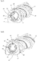
- THE figures 1 to 11 represent a suction head 2 comprising a connection sleeve 3 to which is intended to be connected an end piece of a rigid or flexible tube, itself connected to a suction system of a vacuum cleaner (not shown).
- a vacuum cleaner (not shown)
- the suction head 2 comprises a main body 4 configured to be moved over a surface to be cleaned.
- the connection sleeve 3 is advantageously mounted in a pivot connection with respect to the main body 4 so as to allow the main body 4 to pivot forwards and backwards when the suction head 2 moves according to a direction of travel D1.
- the main body 4 comprises a sole 5 provided with a lower face 6 configured to be oriented towards the surface to be cleaned, and with a suction orifice 7 opening onto the lower face 6.
- the suction orifice 7 communicates with the connection sleeve 3 through in particular a connecting passage formed at least in part, for example by a flexible connecting conduit.
- the suction port 7 can by example have an elongated shape and extend transversely, and for example perpendicularly, to the direction of movement D1 of the suction head 2.
- the main body 4 further comprises a receiving housing 9 which opens into the underside of the sole 5 via the suction orifice 7, and which is fluidly connected to the connecting passage.
- the receiving housing 9 forms a suction chamber.
- the suction head 2 also comprises a cleaning unit 11 comprising a rotating brush 12 which is rotatably mounted in the receiving housing 9 along an axis of rotation A which is substantially coincident with the central axis of the rotating brush 12
- the rotating brush 12 is removably mounted in the receiving housing 9 and configured to be introduced into and withdrawn from the receiving housing 9 along a mounting direction D2.
- the mounting direction D2 extends transversely, and preferably perpendicularly, to the direction of movement D1 of the suction head 2.
- the main body 4 comprises a passage opening 13 opening into the receiving housing 9 and through which the rotating brush 12 can be introduced into and withdrawn from the receiving housing 9.
- the passage opening 13 is provided on a side face of the main body 4.
- the rotating brush 12 comprises a brush body 14 which is for example tubular, and bristles 15 provided on the outer surface of the brush body 14.
- the brush body 14 is cylindrical with a circular section
- the rotary brush 12 comprises a plurality of rows of bristles extending for example helically around the central axis of the rotary brush 12.
- the rows of bristles could be replaced by elastically deformable lamellae or by a foam cleaning sleeve.
- the cleaning unit 11 further comprises a closure cap 16 which is configured to at least partially close the passage opening 13 when the rotating brush 12 is mounted in the receiving housing 9.
- the closure cap 16 comprises a cap body 17 and locking means configured to lock the cap body 17 on the main body 4.
- the locking means comprise at least one locking member 18, advantageously three locking members 18, which are mounted to move, preferably slide, on the cap body 17 between a locking position in which the locking members 18 cooperate with at at least one locking element provided on the main body 4 so as to prevent retraction of the rotating brush 12 from the receiving housing 9 and a release position in which the locking members 18 release the at least one locking element from so as to allow removal of the rotary brush 12 from the receiving housing 9.
- Each locking member 18 is advantageously a locking bolt.
- the at least one locking element comprises only one locking groove 19 extending at least partly around the passage opening 13, and each locking member 18 is configured to engage in the locking groove 19 when the locking members 18 occupy the locking position.
- the at least one locking element comprises a plurality of locking grooves 19 which are angularly offset from each other with respect to the axis of rotation A of the rotary brush 12 and in each of which is intended to be received a respective locking member 18.
- the locking members 18 are regularly distributed around the axis of rotation A of the rotary brush 12, and each locking member 18 is mounted to move relative to the cap body 17 according to a direction of movement which extends substantially radially to the axis of rotation A of the rotating brush 12.
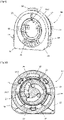
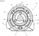
- the locking members 18 are configured to project radially from the outer periphery 21 of the cap body 17 when the locking members 18 occupy the locking position (see the figure 9 And 11 ), and are configured to be set back from or to be substantially flush with the outer periphery 21 of the cap body 17 when the locking members 18 occupy the release position (see the figure 7 And 10 ).
- the locking members 18 and the plug body 17 are immobile in rotation relative to the receiving housing 9 when the plug body 17 is locked on the main body 4.
- the closure cap 16 also includes an actuating member 22 which is configured to move the locking members 18 between the locking position and the releasing position.
- the actuating member 22 may for example have the general shape of a disk.
- the actuating member 22 is mounted so as to be able to rotate relative to the plug body 17, around an actuating axis which is substantially coaxial with the axis of rotation A of the rotary brush 12, between a first actuating position (see the figure 7 ) and a second actuation position (see figure 8 ), and the actuating member 22 and the locking members 18 are configured such that a displacement of the actuating member 22 from the first actuating position to the second actuating position causes a displacement locking members 18 from the release position to the locking position and such that a displacement of the actuating member 22 from the second actuating position to the first actuating position causes a displacement of the members locking 18 from the locking position to the release position.
- Such a configuration of the closure cap 16 allows locking/unlocking of the cap body 17 only by moving the actuating member 22 between the first and second actuating positions, which ensures easy and ergonomic removal of the rotating brush. 12 out of the receiving housing 9.
- the actuating member 22 comprises at least a cam surface which is advantageously formed by a cam groove 23, advantageously three cam grooves 23, in each of which is received a lug 24 provided on a respective locking member 18.
- Each cam groove 23 extends transversely to the axis of rotation A of the rotating brush 12.
- each cam groove 23 is curved and has the general shape of an arc of a circle.
- Each cam groove 23 may have a constant radius of curvature or a gradual radius of curvature. According to a variant embodiment not shown in the figures, each cam groove 23 could however be rectilinear.
- Each cam groove 23 has a first cam surface 23.1 which is configured to move the respective locking member 18 from the release position to the locking position when the actuator member 22 is rotated from the first position. to the second actuating position, and a second cam surface 23.2 which is configured to move the respective locking member 18 from the locking position to the release position when the actuating member 22 is moved in rotation from the second actuation position to the first actuation position.
- the first cam surface 23.1 is formed by a first flank of the groove and the second cam surface 23.2 is formed by a second flank of the groove.
- the second groove flank is advantageously parallel to the first groove flank and the width of the cam groove 23 is substantially greater than the width/diameter of the lug 24 so that the lug 24 is guided in the cam groove 23 when the actuating member 22 is moved in rotation.
- each lug 24 is in sliding contact alternately on the first cam surface 23.1 then on the second cam surface 23.2 so that, when the actuation member 22 is moved from the first actuation position towards the second actuating position, said lug 24 moves by sliding on the first cam surface 23.1, and when the actuating member 22 is moved from the second actuating position to the first position actuation, said lug 24 moves by sliding on the second cam surface 23.2.
- each lug 24 could be in sliding contact simultaneously on the first and second cam surfaces 23.1, 23.2.
- a single cam surface is provided for each locking member.
- return means such as springs, allow each lug to remain in contact with the cam surface.
- each locking member 18 could carry a rolling roller mounted mobile in rotation on each locking member 18 to make rolling contact on the corresponding cam surface of the actuating member or on the first or second surfaces.
- the locking members do not slide on the cam surfaces but roll on the cam surfaces of the actuating member 22 when the latter is for example moved from the first actuation position to the second actuation position.
- the closure cap 16 further comprises a gripping handle 25 configured to be gripped by a user, for example to allow removal of the rotary brush 12 from the receiving housing 9.
- the gripping handle 25 may for example have a semi-circular shape. -circular or any other shape.
- the gripping handle 25 is pivotally mounted on the actuating member 22 between a rest position (see the figure 8 ) and a grip position (see figure 7 ) about a pivot axis which is substantially perpendicular to the axis of rotation A of the rotary brush 12.
- the grip handle 25 and the actuating member 22 are more particularly configured to delimit, when the grip handle 25 occupies the gripping position, a gripping passage capable of receiving at least one finger of a user.
- the actuating member 22 comprises a handle housing 22.1 in which extends at least partially the grip handle 25 when the grip handle 25 occupies the rest position.
- the grip handle 25 may include a grip projection which projects out of the handle housing 22.1 when the grip handle 25 is in the rest position and which is configured to be grasped by a user when the grip handle 25 occupies the rest position so as to be able to move the grip handle 25 from the rest position to the grip position.
- the grip handle 25 is more particularly configured to move the actuation member 22 from the first actuation position to the second actuation position when a first rotational torque is applied to the grip handle 25 by a user. in a first direction of rotation, and to move the actuating member 22 from the second actuating position to the first actuating position when a second rotational torque is applied to the grip handle 25 by a user in a second direction of rotation opposite to the first direction of rotation.
- the closure cap 16 comprises a fixing cap 26 which is fixed to the cap body 17.
- the fixing cap 26 and the cap body 17 delimit a mounting housing in which is mounted the actuating member 22, and are configured to only allow a rotational movement of the actuating member 22 relative to the cap body 17.
- the fixing cover 26 is annular, extends around of the actuating member 22 and partially covers the actuating member 22.
- the actuating member 22 comprises a reading marker 27 and the fixing cover comprises a locking marker 28 and a release marker 29 which are angularly offset with respect to the axis of rotation A of the rotary brush 12.
- the reading marker 27 is configured to be located opposite the release marker 29 when the actuating member 22 occupies the first actuation position and to be located opposite the locking 28 when the actuating member 22 occupies the second actuating position.
- the suction head 2 comprises a keying device 31 configured to impose a relative angular orientation between the closure plug 16 and the main body 4 during insertion of the plug body 17 into the passage opening 13.
- the polarizing device comprises a pair of polarizing elements 32, such as two polarizing ribs, provided on the cap body 17, and the passage opening 13 has a non-circular shape.
- the suction head 2 also includes a drive device 33 configured to drive the rotary brush 12 in rotation around the axis of rotation A of the latter.
- the drive device 33 more particularly comprises an electric drive motor 34 whose output axis can be substantially aligned with the axis of rotation A of the rotating brush 12.
- the electric drive motor 34 is housed in the brush body 14 of the rotating brush 12.
- the electric drive motor 34 could be offset with respect to the axis of rotation A of the rotating brush 12.
- the rotating brush 12 comprises a first end portion 12.1 configured to be coupled in rotation to the drive device 33, and a second end portion 12.2 supported by the closure cap 16 and mounted so as to be able to move in rotation by relative to the closure plug 16.
- the drive device 33 comprises a coupling member 35 which is integral in rotation with the output shaft of the electric drive motor 33 and which is coupled in rotation with the first end portion 12.1 of the rotating brush 12.
- the user moves the gripping handle 25 into the gripping position and applies a torque of rotation on the grip handle 25 so as to move the actuating member 22 into the first actuating position.
- Such movement of the actuating member 22 causes the locking members 18 to move into the release position.
- the user can then easily remove the rotating brush 12 from the receiving housing 9 by exerting a traction force on the grip handle 25 in order to clean or replace the rotating brush 12.
Landscapes
- Engineering & Computer Science (AREA)
- Mechanical Engineering (AREA)
- Nozzles For Electric Vacuum Cleaners (AREA)
Claims (20)
- Reinigungseinheit (11) für einen Saugkopf, umfassend:- eine Drehbürste (12), die um eine Drehachse (A) drehbeweglich ist und die dafür ausgelegt ist, herausnehmbar in einem Aufnahmefach (9), das von einem Hauptkörper (4) des Saugkopfs begrenzt wird, angebracht zu werden, und- einen Verschlussstopfen (16), der dafür ausgelegt ist, eine Durchgangsöffnung (13), die am Hauptkörper (4) vorgesehen ist und durch die die Drehbürste (12) in das Aufnahmefach (9) eingeführt und aus dem Aufnahmefach (9) herausgezogen werden kann, mindestens teilweise zu verschließen, wobei die Drehbürste (12) in Bezug auf den Verschlussstopfen (16) drehfähig ist, wobei der Verschlussstopfen (16) einen Stopfenkörper (17) und Verriegelungsmittel umfasst, die dafür ausgelegt sind, den Stopfenkörper (17) am Hauptkörper (4) zu verriegeln,wobei die Verriegelungsmittel mindestens ein Verriegelungsglied (18) umfassen, das in Bezug auf den Stopfenkörper (17) zwischen einer Verriegelungsstellung, in der das mindestens eine Verriegelungsglied (18) mit mindestens einem am Hauptkörper (4) vorgesehenen Verriegelungselement zusammenwirkt, um ein Herausziehen der Drehbürste (12) aus dem Aufnahmefach (9) zu verhindern, und einer Freigabestellung beweglich ist, in der das mindestens eine Verriegelungsglied (18) das mindestens eine Verriegelungselement freigibt, um ein Herausziehen der Drehbürste (12) aus dem Aufnahmefach (9) zu gestatten,wobei der Verschlussstopfen (16) ein Betätigungsglied (22) umfasst, das sich zwischen einer ersten Betätigungsstellung und einer zweiten Betätigungsstellung verlagern kann, dadurch gekennzeichnet, dass das Betätigungsglied (22) mindestens eine Nockenfläche (23.1, 23.2) umfasst, unddadurch, dass das mindestens eine Verriegelungsglied (18) mindestens eine Kontaktfläche umfasst, die die Nockenfläche (23.1, 23.2) kontaktiert und die dafür ausgelegt ist, sich so entlang der Nockenfläche (23.1, 23.2) zu verlagern, dass wenn das Betätigungsglied (22) zwischen der ersten Betätigungsstellung und der zweiten Betätigungsstellung verlagert wird, die Kontaktfläche sich entlang der Nockenfläche (23.1, 23.2) verlagert, um eine Verlagerung des mindestens einen Verriegelungsglieds (18) zwischen der Freigabestellung und der Verriegelungsstellung zu bewirken.
- Reinigungseinheit (11) nach dem vorstehenden Anspruch, wobei das Betätigungsglied (22) um eine Betätigungsachse, die im Wesentlichen zur Drehachse (A) der Drehbürste (12) parallel ist, drehbeweglich angebracht ist.
- Reinigungseinheit (11) nach Anspruch 1 oder 2, wobei das mindestens eine Verriegelungsglied (18) in Bezug auf den Stopfenkörper (17) in einer Verlagerungsrichtung beweglich ist, die sich quer zur Drehachse (A) der Drehbürste (12) erstreckt.
- Reinigungseinheit (11) nach dem vorstehenden Anspruch, wobei die Verlagerungsrichtung des mindestens einen Verriegelungsglieds (18) im Wesentlichen radial in Bezug auf die Drehachse (A) der Drehbürste (12) verläuft.
- Reinigungseinheit (11) nach einem der vorstehenden Ansprüche, wobei das mindestens eine Verriegelungsglied (18) dafür ausgelegt ist, radial von einem Außenumfang des Stopfenkörpers (17) vorzuspringen, wenn das mindestens eine Verriegelungsglied (18) die Verriegelungsstellung einnimmt.
- Reinigungseinheit (11) nach einem der vorstehenden Ansprüche, wobei das mindestens eine Verriegelungsglied (18) in Bezug auf den Stopfenkörper (17) gleitfähig angebracht ist.
- Reinigungseinheit (11) nach einem der vorstehenden Ansprüche, wobei sich die mindestens eine Nockenfläche (23.1, 23.2) quer zur Drehachse (A) der Drehbürste (12) erstreckt.
- Reinigungseinheit (11) nach einem der vorstehenden Ansprüche, wobei die mindestens eine Kontaktfläche von einer Außenfläche eines Zapfens (24) hergestellt wird, der vom Verriegelungsglied (18) vorspringt und der dafür ausgelegt ist, auf der mindestens einen Nockenfläche (23.1, 23.2) zu gleiten.
- Reinigungseinheit (11) nach dem vorstehenden Anspruch, wobei der Zapfen (24) vom Verriegelungsglied (18) in einer Richtung vorspringt, die zur Drehachse (A) der Drehbürste (12) parallel ist.
- Reinigungseinheit (11) nach einem der vorstehenden Ansprüche, wobei das Betätigungsglied (22) mindestens einen Nockenschlitz (23) umfasst, in dem die mindestens eine Nockenfläche (23.1, 23.2) gebildet ist.
- Reinigungseinheit (11) nach dem vorstehenden Anspruch, wobei sich der mindestens eine Nockenschlitz (23) quer zur Drehachse (A) der Drehbürste (12) erstreckt.
- Reinigungseinheit (11) nach einem der Ansprüche 10 oder 11, wobei der Zapfen (24) in dem Nockenschlitz (23) aufgenommen ist und so in dem Nockenschlitz (23) gleitet, dass wenn das Betätigungsglied (22) zwischen der ersten Betätigungsstellung und der zweiten Betätigungsstellung verlagert wird, der Zapfen (24) sich in dem Nockenschlitz (23) verlagert, indem er auf der mindestens einen Nockenfläche (23.1, 23.2) rutscht, und eine Verlagerung des Verriegelungsglieds (18) zwischen der Freigabestellung und der Verriegelungsstellung bewirkt.
- Reinigungseinheit (11) nach einem der Ansprüche 10 bis 12, wobei der mindestens eine Nockenschlitz (23) eine erste Nockenfläche (23.1), die dafür ausgelegt ist, das mindestens eine Verriegelungsglied (18) von der Freigabestellung zur Verriegelungsstellung zu verlagern, wenn das Betätigungsglied (22) von der ersten Betätigungsstellung zur zweiten Betätigungsstellung verlagert wird, und eine zweite Nockenfläche (23.2) umfasst, die dafür ausgelegt ist, das mindestens eine Verriegelungsglied (18) von der Verriegelungsstellung zur Freigabestellung zu verlagern, wenn das Betätigungsglied (22) von der zweiten Betätigungsstellung zur ersten Betätigungsstellung verlagert wird.
- Reinigungseinheit (11) nach einem der Ansprüche 1 bis 7, wobei die Kontaktfläche von einer Umfangsfläche einer Rolle hergestellt wird, die drehbeweglich am Verriegelungsglied (18) angebracht ist und die dafür ausgelegt ist, auf der Nockenfläche (23.1, 23.2) zu rollen.
- Reinigungseinheit (11) nach einem der Ansprüche 1 bis 14, wobei die Verriegelungsmittel eine Vielzahl von Verriegelungsgliedern (18), die in Bezug auf die Drehachse (A) der Drehbürste (12) winkelmäßig voneinander versetzt sind, vorzugsweise drei Verriegelungsglieder umfassen, wobei das Betätigungsglied (22) eine entsprechende Anzahl von Nockenflächen (23.1, 23.2) umfasst.
- Reinigungseinheit (11) nach einem der Ansprüche 1 bis 15, wobei der Verschlussstopfen (16) einen Handgriff (25) umfasst, der dafür ausgelegt ist, von einem Benutzer gegriffen zu werden.
- Reinigungseinheit (11) nach einem der Ansprüche 1 bis 16, wobei die Drehbürste (12) in dem oder um den Stopfenkörper (17) drehgeführt wird.
- Saugkopf, umfassend:- einen Hauptkörper (4), der ein Aufnahmefach (9), das in einer Unterseite des Hauptkörpers (4) mündet, die dafür ausgelegt ist, zu einer zu reinigenden Fläche hin ausgerichtet zu werden, eine Durchgangsöffnung (13), die in dem Aufnahmefach (9) mündet, und mindestens ein Verriegelungselement umfasst, und- eine Reinigungseinheit (11) nach einem der vorstehenden Ansprüche, wobei die Drehbürste (12) herausnehmbar in dem Aufnahmefach (9) angebracht ist, wobei der Verschlussstopfen (16) die Durchgangsöffnung (13) mindestens teilweise verschließt, und wobei das mindestens eine Verriegelungsglied (18) mit dem mindestens einen Verriegelungselement zusammenwirkt.
- Saugkopf nach Anspruch 18, wobei das mindestens eine Verriegelungselement mindestens einen Verriegelungsschlitz (19) umfasst, in den das mindestens eine Verriegelungsglied (18) auslegungsgemäß einrückt, wenn das mindestens eine Verriegelungsglied (18) die Verriegelungsstellung einnimmt.
- Saugkopf nach Anspruch 18 oder 19, wobei das mindestens eine Verriegelungsglied (18) und der Stopfenkörper (17) in Bezug auf das Aufnahmefach (9) drehunbeweglich sind, wenn der Stopfenkörper (17) am Hauptkörper (4) verriegelt ist.
Applications Claiming Priority (1)
| Application Number | Priority Date | Filing Date | Title |
|---|---|---|---|
| FR2004036A FR3109514B1 (fr) | 2020-04-23 | 2020-04-23 | Unité de nettoyage pour tête d’aspiration |
Publications (2)
| Publication Number | Publication Date |
|---|---|
| EP3900596A1 EP3900596A1 (de) | 2021-10-27 |
| EP3900596B1 true EP3900596B1 (de) | 2023-02-22 |
Family
ID=71094581
Family Applications (1)
| Application Number | Title | Priority Date | Filing Date |
|---|---|---|---|
| EP21169522.6A Active EP3900596B1 (de) | 2020-04-23 | 2021-04-20 | Reinigungseinheit für saugkopf |
Country Status (4)
| Country | Link |
|---|---|
| EP (1) | EP3900596B1 (de) |
| CN (1) | CN113545698B (de) |
| ES (1) | ES2940743T3 (de) |
| FR (1) | FR3109514B1 (de) |
Cited By (2)
| Publication number | Priority date | Publication date | Assignee | Title |
|---|---|---|---|---|
| FR3155697A1 (fr) * | 2023-11-28 | 2025-05-30 | Seb S.A. | Unité de nettoyage pour tête d’aspiration |
| EP4659640A1 (de) * | 2024-06-06 | 2025-12-10 | Zhejiang Shaoxing Supor Domestic Electrical Appliance Co., Ltd. | Bodenbürstenanordnung und reinigungsvorrichtung |
Families Citing this family (12)
| Publication number | Priority date | Publication date | Assignee | Title |
|---|---|---|---|---|
| USD1069288S1 (en) * | 2022-08-31 | 2025-04-01 | Dyson Technology Limited | Vacuum cleaner head |
| USD1069287S1 (en) * | 2022-08-31 | 2025-04-01 | Dyson Technology Limited | Vacuum cleaner head |
| JP1756692S (ja) * | 2022-08-31 | 2024-05-10 | 電気掃除機用吸込み口 | |
| JP1756691S (ja) * | 2022-08-31 | 2024-05-10 | 電気掃除機用吸込み口 | |
| USD1059709S1 (en) * | 2022-08-31 | 2025-01-28 | Dyson Technology Limited | Vacuum cleaner head |
| USD1069297S1 (en) * | 2022-08-31 | 2025-04-01 | Dyson Technology Limited | Vacuum cleaner head |
| USD1069293S1 (en) * | 2022-08-31 | 2025-04-01 | Dyson Technology Limited | Vacuum cleaner head |
| USD1069299S1 (en) * | 2022-08-31 | 2025-04-01 | Dyson Technology Limited | Vacuum cleaner head |
| JP1756694S (ja) * | 2022-08-31 | 2024-05-10 | 電気掃除機用吸込み口 | |
| USD1069291S1 (en) * | 2022-08-31 | 2025-04-01 | Dyson Technology Limited | Vacuum cleaner head |
| JP1756695S (ja) * | 2022-08-31 | 2024-05-10 | 電気掃除機用吸込み口 | |
| JP1756417S (ja) * | 2022-08-31 | 2024-05-10 | 電気掃除機用吸込み口 |
Family Cites Families (16)
| Publication number | Priority date | Publication date | Assignee | Title |
|---|---|---|---|---|
| JP2000354569A (ja) * | 1999-04-13 | 2000-12-26 | Matsushita Electric Ind Co Ltd | 電気掃除機用吸込具並びに電気掃除機 |
| JP4100672B2 (ja) * | 2002-09-30 | 2008-06-11 | 株式会社東芝 | 回転清掃体、電気掃除機の吸込口体および回転清掃体の製造方法 |
| JP2004180731A (ja) * | 2002-11-29 | 2004-07-02 | Toshiba Tec Corp | 電気掃除機 |
| EP1535843B1 (de) * | 2003-11-28 | 2007-10-10 | KPL Packaging S.p.A. | Verpackungsmaschine für die Produktumwicklung in korrespondierenden Zuschnitten aus heisssiegelbarem Umwicklungsmaterial |
| JP2005312589A (ja) * | 2004-04-28 | 2005-11-10 | Mitsubishi Electric Corp | 電気掃除機の吸込具 |
| KR100734960B1 (ko) * | 2006-09-25 | 2007-07-03 | 삼성광주전자 주식회사 | 업라이트형 진공청소기의 흡입구체의 높이조절장치 |
| CN201001692Y (zh) * | 2007-01-15 | 2008-01-09 | 张建明 | 金属伸缩管锁定装置 |
| AU2011203209B2 (en) * | 2010-07-06 | 2014-02-13 | Bissell Inc. | Vacuum cleaner with modular clutch assembly |
| FI122802B (fi) * | 2010-09-27 | 2012-07-13 | Metso Paper Inc | Taipumakompensoitu tela |
| GB2508153B (en) * | 2012-11-21 | 2015-03-11 | Dyson Technology Ltd | Cleaner head for a cleaning appliance |
| DE102014010098B4 (de) * | 2014-05-06 | 2017-07-20 | Stein & Co. Gmbh | Bodenpflegegerät |
| DE202016105655U1 (de) * | 2016-10-10 | 2018-01-11 | Vorwerk & Co. Interholding Gmbh | Reinigungsgerät mit einem angetriebenen, drehbaren Bürstenkörper |
| GB2562523B (en) * | 2017-05-18 | 2019-11-13 | Dyson Technology Ltd | A cleaner head |
| CN209269558U (zh) * | 2018-07-11 | 2019-08-20 | 尚科宁家(香港)股份有限公司 | 一种吸尘器吸头 |
| FR3084574B1 (fr) * | 2018-08-03 | 2020-07-03 | Seb S.A. | Tete de nettoyage equipee d'une brosse rotative |
| CN110772170A (zh) * | 2019-11-07 | 2020-02-11 | 小狗电器互联网科技(北京)股份有限公司 | 一种地刷及其装配方法 |
-
2020
- 2020-04-23 FR FR2004036A patent/FR3109514B1/fr active Active
-
2021
- 2021-04-20 ES ES21169522T patent/ES2940743T3/es active Active
- 2021-04-20 EP EP21169522.6A patent/EP3900596B1/de active Active
- 2021-04-21 CN CN202110429555.8A patent/CN113545698B/zh active Active
Cited By (3)
| Publication number | Priority date | Publication date | Assignee | Title |
|---|---|---|---|---|
| FR3155697A1 (fr) * | 2023-11-28 | 2025-05-30 | Seb S.A. | Unité de nettoyage pour tête d’aspiration |
| EP4563053A1 (de) * | 2023-11-28 | 2025-06-04 | Seb S.A. | Reinigungseinheit für einen saugkopf |
| EP4659640A1 (de) * | 2024-06-06 | 2025-12-10 | Zhejiang Shaoxing Supor Domestic Electrical Appliance Co., Ltd. | Bodenbürstenanordnung und reinigungsvorrichtung |
Also Published As
| Publication number | Publication date |
|---|---|
| FR3109514B1 (fr) | 2022-04-29 |
| CN113545698A (zh) | 2021-10-26 |
| CN113545698B (zh) | 2025-11-25 |
| ES2940743T3 (es) | 2023-05-11 |
| FR3109514A1 (fr) | 2021-10-29 |
| EP3900596A1 (de) | 2021-10-27 |
Similar Documents
| Publication | Publication Date | Title |
|---|---|---|
| EP3900596A1 (de) | Reinigungseinheit für saugkopf | |
| EP3900594B1 (de) | Reinigungseinheit für saugkopf | |
| EP2394503B1 (de) | Rotierender Schneidekopf, der Schneideblätter verwendet, und mit einem solchen Schneidekopf ausgestattete Schneidegeräte | |
| EP3900595B1 (de) | Reinigungseinheit für saugkopf | |
| EP3725203B1 (de) | Ansaugkopf | |
| EP3656268B1 (de) | Saugrohr für besenstaubsauger mit elektrischem kabel | |
| EP3900597B1 (de) | Drehbürste für saugkopf | |
| EP3666144B1 (de) | Staubsaugerroboter | |
| CA2597776C (fr) | Bouton tournant a serrure | |
| EP3834691B1 (de) | Reinigungskopf ausgestattet mit einem abnehmbaren reinigungselement | |
| EP3624660B1 (de) | Autonomer staubsauger mit drehbarem stab | |
| EP4311465B1 (de) | Reinigungseinheit für einen saugkopf | |
| EP4098170B1 (de) | Zubehör für schlittenstaubsauger, der mit einer beweglichen gelenkabdeckung ausgestattet ist | |
| EP4098163B1 (de) | Zubehör für schlittenstaubsauger | |
| EP4563053A1 (de) | Reinigungseinheit für einen saugkopf | |
| FR2809694A1 (fr) | Mecanisme d'escamotage d'un brin boucle de ceinture de securite | |
| EP0410830A1 (de) | Sicherheitsschloss mit entkuppelbarem Stator | |
| EP0444972B1 (de) | Schloss mit einem Stator und einem frei rotierenden im Stator montierten Rotor | |
| EP3747328B1 (de) | Saugdüse eines staubsaugers, die mit einem gabelstück ausgestattet ist, und verriegelungsvorrichtung zum blockieren des schwingens des gabelstücks | |
| EP4356805A1 (de) | Staubsaugerkanal mit gelenkvorrichtung | |
| FR2815067A1 (fr) | Cylindre de surete a barillet prioritaire | |
| EP4497361A1 (de) | Staubsaugerkanal mit gelenkvorrichtung | |
| FR3151645A1 (fr) | Conduit flexible pourvu d’un ergot de verrouillage | |
| EP0869236B1 (de) | Von einer Seite aus betätigbarer Sicherheitszylinder selbst wenn ein Schlüssel auf der anderen Seite eingesteckt ist | |
| FR3141053A1 (fr) | Conduit d’aspirateur équipé d’un dispositif d’articulation |
Legal Events
| Date | Code | Title | Description |
|---|---|---|---|
| PUAI | Public reference made under article 153(3) epc to a published international application that has entered the european phase |
Free format text: ORIGINAL CODE: 0009012 |
|
| STAA | Information on the status of an ep patent application or granted ep patent |
Free format text: STATUS: THE APPLICATION HAS BEEN PUBLISHED |
|
| AK | Designated contracting states |
Kind code of ref document: A1 Designated state(s): AL AT BE BG CH CY CZ DE DK EE ES FI FR GB GR HR HU IE IS IT LI LT LU LV MC MK MT NL NO PL PT RO RS SE SI SK SM TR |
|
| B565 | Issuance of search results under rule 164(2) epc |
Effective date: 20210907 |
|
| STAA | Information on the status of an ep patent application or granted ep patent |
Free format text: STATUS: REQUEST FOR EXAMINATION WAS MADE |
|
| 17P | Request for examination filed |
Effective date: 20220419 |
|
| RBV | Designated contracting states (corrected) |
Designated state(s): AL AT BE BG CH CY CZ DE DK EE ES FI FR GB GR HR HU IE IS IT LI LT LU LV MC MK MT NL NO PL PT RO RS SE SI SK SM TR |
|
| GRAP | Despatch of communication of intention to grant a patent |
Free format text: ORIGINAL CODE: EPIDOSNIGR1 |
|
| STAA | Information on the status of an ep patent application or granted ep patent |
Free format text: STATUS: GRANT OF PATENT IS INTENDED |
|
| RIC1 | Information provided on ipc code assigned before grant |
Ipc: A47L 9/04 20060101AFI20220816BHEP |
|
| INTG | Intention to grant announced |
Effective date: 20220914 |
|
| GRAS | Grant fee paid |
Free format text: ORIGINAL CODE: EPIDOSNIGR3 |
|
| GRAA | (expected) grant |
Free format text: ORIGINAL CODE: 0009210 |
|
| STAA | Information on the status of an ep patent application or granted ep patent |
Free format text: STATUS: THE PATENT HAS BEEN GRANTED |
|
| AK | Designated contracting states |
Kind code of ref document: B1 Designated state(s): AL AT BE BG CH CY CZ DE DK EE ES FI FR GB GR HR HU IE IS IT LI LT LU LV MC MK MT NL NO PL PT RO RS SE SI SK SM TR |
|
| REG | Reference to a national code |
Ref country code: GB Ref legal event code: FG4D Free format text: NOT ENGLISH |
|
| REG | Reference to a national code |
Ref country code: CH Ref legal event code: EP |
|
| REG | Reference to a national code |
Ref country code: DE Ref legal event code: R096 Ref document number: 602021001442 Country of ref document: DE |
|
| REG | Reference to a national code |
Ref country code: AT Ref legal event code: REF Ref document number: 1548987 Country of ref document: AT Kind code of ref document: T Effective date: 20230315 Ref country code: IE Ref legal event code: FG4D Free format text: LANGUAGE OF EP DOCUMENT: FRENCH |
|
| REG | Reference to a national code |
Ref country code: ES Ref legal event code: FG2A Ref document number: 2940743 Country of ref document: ES Kind code of ref document: T3 Effective date: 20230511 |
|
| REG | Reference to a national code |
Ref country code: LT Ref legal event code: MG9D |
|
| REG | Reference to a national code |
Ref country code: NL Ref legal event code: MP Effective date: 20230222 |
|
| REG | Reference to a national code |
Ref country code: AT Ref legal event code: MK05 Ref document number: 1548987 Country of ref document: AT Kind code of ref document: T Effective date: 20230222 |
|
| PG25 | Lapsed in a contracting state [announced via postgrant information from national office to epo] |
Ref country code: RS Free format text: LAPSE BECAUSE OF FAILURE TO SUBMIT A TRANSLATION OF THE DESCRIPTION OR TO PAY THE FEE WITHIN THE PRESCRIBED TIME-LIMIT Effective date: 20230222 Ref country code: PT Free format text: LAPSE BECAUSE OF FAILURE TO SUBMIT A TRANSLATION OF THE DESCRIPTION OR TO PAY THE FEE WITHIN THE PRESCRIBED TIME-LIMIT Effective date: 20230622 Ref country code: NO Free format text: LAPSE BECAUSE OF FAILURE TO SUBMIT A TRANSLATION OF THE DESCRIPTION OR TO PAY THE FEE WITHIN THE PRESCRIBED TIME-LIMIT Effective date: 20230522 Ref country code: NL Free format text: LAPSE BECAUSE OF FAILURE TO SUBMIT A TRANSLATION OF THE DESCRIPTION OR TO PAY THE FEE WITHIN THE PRESCRIBED TIME-LIMIT Effective date: 20230222 Ref country code: LV Free format text: LAPSE BECAUSE OF FAILURE TO SUBMIT A TRANSLATION OF THE DESCRIPTION OR TO PAY THE FEE WITHIN THE PRESCRIBED TIME-LIMIT Effective date: 20230222 Ref country code: LT Free format text: LAPSE BECAUSE OF FAILURE TO SUBMIT A TRANSLATION OF THE DESCRIPTION OR TO PAY THE FEE WITHIN THE PRESCRIBED TIME-LIMIT Effective date: 20230222 Ref country code: HR Free format text: LAPSE BECAUSE OF FAILURE TO SUBMIT A TRANSLATION OF THE DESCRIPTION OR TO PAY THE FEE WITHIN THE PRESCRIBED TIME-LIMIT Effective date: 20230222 Ref country code: AT Free format text: LAPSE BECAUSE OF FAILURE TO SUBMIT A TRANSLATION OF THE DESCRIPTION OR TO PAY THE FEE WITHIN THE PRESCRIBED TIME-LIMIT Effective date: 20230222 |
|
| PG25 | Lapsed in a contracting state [announced via postgrant information from national office to epo] |
Ref country code: SE Free format text: LAPSE BECAUSE OF FAILURE TO SUBMIT A TRANSLATION OF THE DESCRIPTION OR TO PAY THE FEE WITHIN THE PRESCRIBED TIME-LIMIT Effective date: 20230222 Ref country code: PL Free format text: LAPSE BECAUSE OF FAILURE TO SUBMIT A TRANSLATION OF THE DESCRIPTION OR TO PAY THE FEE WITHIN THE PRESCRIBED TIME-LIMIT Effective date: 20230222 Ref country code: IS Free format text: LAPSE BECAUSE OF FAILURE TO SUBMIT A TRANSLATION OF THE DESCRIPTION OR TO PAY THE FEE WITHIN THE PRESCRIBED TIME-LIMIT Effective date: 20230622 Ref country code: GR Free format text: LAPSE BECAUSE OF FAILURE TO SUBMIT A TRANSLATION OF THE DESCRIPTION OR TO PAY THE FEE WITHIN THE PRESCRIBED TIME-LIMIT Effective date: 20230523 Ref country code: FI Free format text: LAPSE BECAUSE OF FAILURE TO SUBMIT A TRANSLATION OF THE DESCRIPTION OR TO PAY THE FEE WITHIN THE PRESCRIBED TIME-LIMIT Effective date: 20230222 |
|
| PG25 | Lapsed in a contracting state [announced via postgrant information from national office to epo] |
Ref country code: SM Free format text: LAPSE BECAUSE OF FAILURE TO SUBMIT A TRANSLATION OF THE DESCRIPTION OR TO PAY THE FEE WITHIN THE PRESCRIBED TIME-LIMIT Effective date: 20230222 Ref country code: RO Free format text: LAPSE BECAUSE OF FAILURE TO SUBMIT A TRANSLATION OF THE DESCRIPTION OR TO PAY THE FEE WITHIN THE PRESCRIBED TIME-LIMIT Effective date: 20230222 Ref country code: EE Free format text: LAPSE BECAUSE OF FAILURE TO SUBMIT A TRANSLATION OF THE DESCRIPTION OR TO PAY THE FEE WITHIN THE PRESCRIBED TIME-LIMIT Effective date: 20230222 Ref country code: DK Free format text: LAPSE BECAUSE OF FAILURE TO SUBMIT A TRANSLATION OF THE DESCRIPTION OR TO PAY THE FEE WITHIN THE PRESCRIBED TIME-LIMIT Effective date: 20230222 Ref country code: CZ Free format text: LAPSE BECAUSE OF FAILURE TO SUBMIT A TRANSLATION OF THE DESCRIPTION OR TO PAY THE FEE WITHIN THE PRESCRIBED TIME-LIMIT Effective date: 20230222 |
|
| REG | Reference to a national code |
Ref country code: DE Ref legal event code: R097 Ref document number: 602021001442 Country of ref document: DE |
|
| PG25 | Lapsed in a contracting state [announced via postgrant information from national office to epo] |
Ref country code: SK Free format text: LAPSE BECAUSE OF FAILURE TO SUBMIT A TRANSLATION OF THE DESCRIPTION OR TO PAY THE FEE WITHIN THE PRESCRIBED TIME-LIMIT Effective date: 20230222 |
|
| PG25 | Lapsed in a contracting state [announced via postgrant information from national office to epo] |
Ref country code: LU Free format text: LAPSE BECAUSE OF NON-PAYMENT OF DUE FEES Effective date: 20230420 |
|
| PLBE | No opposition filed within time limit |
Free format text: ORIGINAL CODE: 0009261 |
|
| STAA | Information on the status of an ep patent application or granted ep patent |
Free format text: STATUS: NO OPPOSITION FILED WITHIN TIME LIMIT |
|
| REG | Reference to a national code |
Ref country code: BE Ref legal event code: MM Effective date: 20230430 |
|
| PG25 | Lapsed in a contracting state [announced via postgrant information from national office to epo] |
Ref country code: MC Free format text: LAPSE BECAUSE OF FAILURE TO SUBMIT A TRANSLATION OF THE DESCRIPTION OR TO PAY THE FEE WITHIN THE PRESCRIBED TIME-LIMIT Effective date: 20230222 |
|
| 26N | No opposition filed |
Effective date: 20231123 |
|
| PG25 | Lapsed in a contracting state [announced via postgrant information from national office to epo] |
Ref country code: SI Free format text: LAPSE BECAUSE OF FAILURE TO SUBMIT A TRANSLATION OF THE DESCRIPTION OR TO PAY THE FEE WITHIN THE PRESCRIBED TIME-LIMIT Effective date: 20230222 Ref country code: MC Free format text: LAPSE BECAUSE OF FAILURE TO SUBMIT A TRANSLATION OF THE DESCRIPTION OR TO PAY THE FEE WITHIN THE PRESCRIBED TIME-LIMIT Effective date: 20230222 |
|
| REG | Reference to a national code |
Ref country code: IE Ref legal event code: MM4A |
|
| PG25 | Lapsed in a contracting state [announced via postgrant information from national office to epo] |
Ref country code: BE Free format text: LAPSE BECAUSE OF NON-PAYMENT OF DUE FEES Effective date: 20230430 |
|
| PG25 | Lapsed in a contracting state [announced via postgrant information from national office to epo] |
Ref country code: IE Free format text: LAPSE BECAUSE OF NON-PAYMENT OF DUE FEES Effective date: 20230420 |
|
| PG25 | Lapsed in a contracting state [announced via postgrant information from national office to epo] |
Ref country code: IE Free format text: LAPSE BECAUSE OF NON-PAYMENT OF DUE FEES Effective date: 20230420 |
|
| PG25 | Lapsed in a contracting state [announced via postgrant information from national office to epo] |
Ref country code: BG Free format text: LAPSE BECAUSE OF FAILURE TO SUBMIT A TRANSLATION OF THE DESCRIPTION OR TO PAY THE FEE WITHIN THE PRESCRIBED TIME-LIMIT Effective date: 20230222 |
|
| PG25 | Lapsed in a contracting state [announced via postgrant information from national office to epo] |
Ref country code: BG Free format text: LAPSE BECAUSE OF FAILURE TO SUBMIT A TRANSLATION OF THE DESCRIPTION OR TO PAY THE FEE WITHIN THE PRESCRIBED TIME-LIMIT Effective date: 20230222 |
|
| REG | Reference to a national code |
Ref country code: CH Ref legal event code: PL |
|
| PG25 | Lapsed in a contracting state [announced via postgrant information from national office to epo] |
Ref country code: CH Free format text: LAPSE BECAUSE OF NON-PAYMENT OF DUE FEES Effective date: 20240430 |
|
| PGFP | Annual fee paid to national office [announced via postgrant information from national office to epo] |
Ref country code: DE Payment date: 20250411 Year of fee payment: 5 |
|
| PGFP | Annual fee paid to national office [announced via postgrant information from national office to epo] |
Ref country code: GB Payment date: 20250417 Year of fee payment: 5 Ref country code: ES Payment date: 20250512 Year of fee payment: 5 |
|
| PGFP | Annual fee paid to national office [announced via postgrant information from national office to epo] |
Ref country code: IT Payment date: 20250409 Year of fee payment: 5 |
|
| PGFP | Annual fee paid to national office [announced via postgrant information from national office to epo] |
Ref country code: FR Payment date: 20250429 Year of fee payment: 5 |
|
| PG25 | Lapsed in a contracting state [announced via postgrant information from national office to epo] |
Ref country code: CY Free format text: LAPSE BECAUSE OF FAILURE TO SUBMIT A TRANSLATION OF THE DESCRIPTION OR TO PAY THE FEE WITHIN THE PRESCRIBED TIME-LIMIT; INVALID AB INITIO Effective date: 20210420 |
|
| PG25 | Lapsed in a contracting state [announced via postgrant information from national office to epo] |
Ref country code: HU Free format text: LAPSE BECAUSE OF FAILURE TO SUBMIT A TRANSLATION OF THE DESCRIPTION OR TO PAY THE FEE WITHIN THE PRESCRIBED TIME-LIMIT; INVALID AB INITIO Effective date: 20210420 |
|
| PG25 | Lapsed in a contracting state [announced via postgrant information from national office to epo] |
Ref country code: TR Free format text: LAPSE BECAUSE OF FAILURE TO SUBMIT A TRANSLATION OF THE DESCRIPTION OR TO PAY THE FEE WITHIN THE PRESCRIBED TIME-LIMIT Effective date: 20230222 |