EP3900519B1 - Plant cultivating apparatus - Google Patents
Plant cultivating apparatus Download PDFInfo
- Publication number
- EP3900519B1 EP3900519B1 EP20213413.6A EP20213413A EP3900519B1 EP 3900519 B1 EP3900519 B1 EP 3900519B1 EP 20213413 A EP20213413 A EP 20213413A EP 3900519 B1 EP3900519 B1 EP 3900519B1
- Authority
- EP
- European Patent Office
- Prior art keywords
- water
- water supply
- supply part
- cultivation
- shelf
- Prior art date
- Legal status (The legal status is an assumption and is not a legal conclusion. Google has not performed a legal analysis and makes no representation as to the accuracy of the status listed.)
- Active
Links
Images


Classifications
-
- A—HUMAN NECESSITIES
- A01—AGRICULTURE; FORESTRY; ANIMAL HUSBANDRY; HUNTING; TRAPPING; FISHING
- A01G—HORTICULTURE; CULTIVATION OF VEGETABLES, FLOWERS, RICE, FRUIT, VINES, HOPS OR SEAWEED; FORESTRY; WATERING
- A01G27/00—Self-acting watering devices, e.g. for flower-pots
- A01G27/003—Control of self-acting watering devices
-
- A—HUMAN NECESSITIES
- A01—AGRICULTURE; FORESTRY; ANIMAL HUSBANDRY; HUNTING; TRAPPING; FISHING
- A01G—HORTICULTURE; CULTIVATION OF VEGETABLES, FLOWERS, RICE, FRUIT, VINES, HOPS OR SEAWEED; FORESTRY; WATERING
- A01G31/00—Soilless cultivation, e.g. hydroponics
- A01G31/02—Special apparatus therefor
- A01G31/06—Hydroponic culture on racks or in stacked containers
-
- A—HUMAN NECESSITIES
- A01—AGRICULTURE; FORESTRY; ANIMAL HUSBANDRY; HUNTING; TRAPPING; FISHING
- A01G—HORTICULTURE; CULTIVATION OF VEGETABLES, FLOWERS, RICE, FRUIT, VINES, HOPS OR SEAWEED; FORESTRY; WATERING
- A01G9/00—Cultivation in receptacles, forcing-frames or greenhouses; Edging for beds, lawn or the like
- A01G9/14—Greenhouses
- A01G9/16—Dismountable or portable greenhouses ; Greenhouses with sliding roofs
-
- A—HUMAN NECESSITIES
- A01—AGRICULTURE; FORESTRY; ANIMAL HUSBANDRY; HUNTING; TRAPPING; FISHING
- A01G—HORTICULTURE; CULTIVATION OF VEGETABLES, FLOWERS, RICE, FRUIT, VINES, HOPS OR SEAWEED; FORESTRY; WATERING
- A01G27/00—Self-acting watering devices, e.g. for flower-pots
- A01G27/005—Reservoirs connected to flower-pots through conduits
-
- A—HUMAN NECESSITIES
- A01—AGRICULTURE; FORESTRY; ANIMAL HUSBANDRY; HUNTING; TRAPPING; FISHING
- A01G—HORTICULTURE; CULTIVATION OF VEGETABLES, FLOWERS, RICE, FRUIT, VINES, HOPS OR SEAWEED; FORESTRY; WATERING
- A01G27/00—Self-acting watering devices, e.g. for flower-pots
- A01G27/008—Component parts, e.g. dispensing fittings, level indicators
-
- A—HUMAN NECESSITIES
- A01—AGRICULTURE; FORESTRY; ANIMAL HUSBANDRY; HUNTING; TRAPPING; FISHING
- A01G—HORTICULTURE; CULTIVATION OF VEGETABLES, FLOWERS, RICE, FRUIT, VINES, HOPS OR SEAWEED; FORESTRY; WATERING
- A01G27/00—Self-acting watering devices, e.g. for flower-pots
- A01G27/04—Self-acting watering devices, e.g. for flower-pots using wicks or the like
- A01G27/06—Self-acting watering devices, e.g. for flower-pots using wicks or the like having a water reservoir, the main part thereof being located wholly around or directly beside the growth substrate
-
- A—HUMAN NECESSITIES
- A01—AGRICULTURE; FORESTRY; ANIMAL HUSBANDRY; HUNTING; TRAPPING; FISHING
- A01G—HORTICULTURE; CULTIVATION OF VEGETABLES, FLOWERS, RICE, FRUIT, VINES, HOPS OR SEAWEED; FORESTRY; WATERING
- A01G9/00—Cultivation in receptacles, forcing-frames or greenhouses; Edging for beds, lawn or the like
- A01G9/04—Flower-pot saucers
- A01G9/045—Trays for receiving multiple pots
-
- A—HUMAN NECESSITIES
- A01—AGRICULTURE; FORESTRY; ANIMAL HUSBANDRY; HUNTING; TRAPPING; FISHING
- A01G—HORTICULTURE; CULTIVATION OF VEGETABLES, FLOWERS, RICE, FRUIT, VINES, HOPS OR SEAWEED; FORESTRY; WATERING
- A01G27/00—Self-acting watering devices, e.g. for flower-pots
- A01G27/04—Self-acting watering devices, e.g. for flower-pots using wicks or the like
-
- Y—GENERAL TAGGING OF NEW TECHNOLOGICAL DEVELOPMENTS; GENERAL TAGGING OF CROSS-SECTIONAL TECHNOLOGIES SPANNING OVER SEVERAL SECTIONS OF THE IPC; TECHNICAL SUBJECTS COVERED BY FORMER USPC CROSS-REFERENCE ART COLLECTIONS [XRACs] AND DIGESTS
- Y02—TECHNOLOGIES OR APPLICATIONS FOR MITIGATION OR ADAPTATION AGAINST CLIMATE CHANGE
- Y02A—TECHNOLOGIES FOR ADAPTATION TO CLIMATE CHANGE
- Y02A40/00—Adaptation technologies in agriculture, forestry, livestock or agroalimentary production
- Y02A40/10—Adaptation technologies in agriculture, forestry, livestock or agroalimentary production in agriculture
- Y02A40/25—Greenhouse technology, e.g. cooling systems therefor
-
- Y—GENERAL TAGGING OF NEW TECHNOLOGICAL DEVELOPMENTS; GENERAL TAGGING OF CROSS-SECTIONAL TECHNOLOGIES SPANNING OVER SEVERAL SECTIONS OF THE IPC; TECHNICAL SUBJECTS COVERED BY FORMER USPC CROSS-REFERENCE ART COLLECTIONS [XRACs] AND DIGESTS
- Y02—TECHNOLOGIES OR APPLICATIONS FOR MITIGATION OR ADAPTATION AGAINST CLIMATE CHANGE
- Y02P—CLIMATE CHANGE MITIGATION TECHNOLOGIES IN THE PRODUCTION OR PROCESSING OF GOODS
- Y02P60/00—Technologies relating to agriculture, livestock or agroalimentary industries
- Y02P60/20—Reduction of greenhouse gas [GHG] emissions in agriculture, e.g. CO2
- Y02P60/21—Dinitrogen oxide [N2O], e.g. using aquaponics, hydroponics or efficiency measures
Definitions
- the present disclosure relates to a plant cultivating apparatus, and more particularly, to a plant cultivating apparatus for controlling water supply by detecting an amount of water stored in a water supply part.
- Pots are not suitable for cultivating plants that are sensitive to temperature or humidity.
- Plant cultivating apparatuses may set environmental factors such as temperature or humidity required for a specific plant. Accordingly, when a plant cultivating apparatus is used, it becomes possible to germinate and cultivate desired plants, even indoors.
- Korean Patent Application Publication No. 10-2019-0132790 , KR 2019 0132790 A discloses 'a plant cultivating apparatus'.
- Related Art discloses forming a space for cultivating plants inside, and supplying the plants with water and nutrients necessary for their cultivation. However, proper temperature and humidity must be maintained in order to cultivate the plants well. In addition, an adequate amount of water should be supplied to the plants at suitable times.
- Related Art does not disclose a configuration for separately measuring or controlling the amount of water supplied to the plants.
- Supplying plants with the adequate amount of water is important in order to cultivate the plants.
- supplying the plants with the adequate amount of water at suitable times is necessary in order to cultivate the plants well. Therefore, there is a need for improvement in the related technology.
- the above-described background technology is technical information that the inventors have held for the derivation of the present disclosure or that the inventors acquired in the process of deriving the present disclosure. Thus, the above-described background technology cannot be regarded as known technology disclosed to the general public prior to the filing of the present application.
- the present disclosure is directed to addressing a disadvantage in the art in which it is difficult to accurately measure an amount of water supplied to a plant cultivating apparatus.
- the present disclosure is further directed to addressing a disadvantage in the art in which since water needed to cultivate plants is intermittently supplied to a water supply part, too much or too little water is supplied to the water supply part.
- the present disclosure is still further directed to addressing a disadvantage in the art in which since a contact type sensor is used to measure the supplied amount of water, the internal configuration of the plant cultivating apparatus becomes complex and its design becomes difficult.
- the present invention provides a plant cultivating apparatus comprising: a main body that defines a cultivation space and includes a door configured to open or close the cultivation space; a shelf that is disposed at the cultivation space and includes a water level sensor; a cultivation bed that is disposed on the shelf, that defines a receiving space, and that includes a water supply part that is disposed at a bottom surface of the cultivation bed and configured to store water; a cultivation container that is disposed above the water supply part of the cultivation bed; and an elastic member that is disposed between the water level sensor and the shelf and supports the water level sensor on the shelf, wherein the water supply part of the cultivation bed is positioned above the water level sensor of the shelf, and wherein the water level sensor is a non-contact type sensor, and configured to measure an amount of the water stored in the water supply part of the cultivation bed, and wherein the elastic member is configured to bias the water level sensor against the shelf such that, based on the bottom surface of the water supply part of the cultivation bed coming into contact with the water level sensor, the water level sensor is
- the plant cultivating apparatus can optionally include one or more of the following features.
- the bottom surface of the water supply part may include an inclined surface.
- the bottom surface of the water supply part may include a pressurizing protrusion that protrudes downward, the pressurizing protrusion being configured to press the water level sensor vertically, and allowing the water level sensor to be spaced apart from the bottom surface of the water supply part.
- the amount of the water stored in the water supply part may be measured based on a change in capacitance of the water level sensor.
- the cultivation bed may include an inlet and a water supply passage. The inlet may be disposed at the cultivation bed and positioned higher than the water supply part. The inlet may be configured to introduce water to the water supply part.
- the water supply passage may fluidly connect the inlet to the water supply part.
- the cultivation container may define an opening that is configured to introduce the water stored in the water supply part into the cultivation container.
- the cultivation container may include a wick that includes a porous material configured to absorb water. A lower end of the wick may be disposed at the opening of the cultivation container. The wick may extend upward such that an upper end of the wick is disposed inside the cultivation container.
- the main body may include a controller configured to control at least one of temperature, humidity, or an amount of light in the cultivation space.
- the plant cultivating apparatus may include a rail configured to couple the cultivation bed to the shelf.
- the cultivation bed may be configured to slide on the shelf along the rail.
- the water level sensor operates while the cultivation bed is disposed on the shelf.
- the amount of water supplied to the plants can be accurately measured in real time.
- water needed to cultivate the plants can be supplied to the water supply part in real time based on the measured amount of water, it is possible to constantly supply the plants with an adequate amount of water.
- a non-contact type sensor is included in the plant cultivating apparatus to measure the supplied amount of water, it is possible to simplify the internal configuration of the plant cultivating apparatus and to facilitate simpler design thereof.
- the distance between the non-contact type sensor and the space for storing water can be kept constant, it is possible to reliably measure the supplied amount of water.
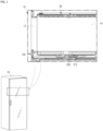
- FIG. 1 is a perspective view and a partial cross-sectional view illustrating a plant cultivating apparatus according to an embodiment of the present disclosure.
- the plant cultivating apparatus includes a main body 10, a shelf 200, and a cultivation bed 100.
- the cultivation bed 100 includes a cultivation container 110 and a tray 130.
- the cultivation container 110 contains a medium.
- the medium is provided to allow plant seeds to be planted and allow plants to take root.
- the medium may be soil containing nutrients that aid in the growth or development of the plants.
- the medium may be made of a material similar to soil.
- the main body 10 has a predetermined space formed therein.
- the predetermined space is a cultivation space 14, which may accommodate the plants and establish an environment for growing the plants.
- the main body 10 may have various sizes and shapes.
- the main body 10 may be formed in a rectangular parallelepiped shape and have the cultivation space 14 formed therein, and at least one of the surfaces forming the cultivation space 14 may be open.
- a door 12 may be coupled to the open surface of the cultivation space 14, and the cultivation space 14 may be opened or closed through the door 12.
- At least a portion of the door 12 may be made of a transparent material. Accordingly, a user may observe the cultivation space 14 through the transparent portion of the door 12.
- the door 12 may be provided with a locking device.
- the locking device of the door 12 may be set to open when the state of the cultivation space 14 meets a predetermined condition. This is to prevent a situation in which the door 12 is opened due to the user's carelessness during germination, which is an important period for the growth of the plants, and the seeds thus cannot germinate.
- the main body 10 and the door 12 may be implemented in various shapes, forms, and materials.
- the main body 10 may be provided with a ventilation device for ventilation therein.
- the ventilation is achieved by discharging air in the cultivation space 14 to the outside or introducing outside air into the cultivation space 14.
- the shelf 200 is disposed in the cultivation space 14.
- a plurality of shelves 200 may be disposed in the cultivation space 14.
- the shelf 200 is a structure that crosses the cultivation space 14 horizontally.
- the cultivation bed 100 is disposed on the shelf 200.
- the shelf 200 supports a load of the cultivation bed 100.
- the plurality of shelves 200 may be vertically disposed in the cultivation space 14.
- at least one cultivation bed 100 may be seated on each shelf 200.
- a controller 20 may be provided above the shelf 200.
- the controller 20 may be disposed at the upper portion of the cultivation space 14, and may include at least one of a steam injector, a heater, or a light irradiator. Accordingly, the controller 2 allows the steam injector, the heater, or the light irradiator to inject steam, emit heat, or irradiate light downward, respectively.
- the controller 20 controls temperature, humidity, and an amount of light in the cultivation space 14. Accordingly, the cultivation space 14 in the main body 10 may be provided with a measuring means capable of measuring the temperature, the humidity, and the amount of light in the cultivation space 14. The controller 20 operates based on the temperature, the humidity, and the amount of light in the cultivation space 14, which are measured by the measuring means, and accordingly, the temperature, the humidity, and the amount of light in the cultivation space 14 can be maintained at predetermined values.
- FIG. 2 is a perspective view illustrating a cultivation bed 100 in the plant cultivating apparatus according to an embodiment of the present disclosure
- FIG. 3 is a perspective view illustrating the cultivation bed 100 and a sensor in the plant cultivating apparatus according to an embodiment of the present disclosure.
- the cultivation bed 100 includes a cultivation container 110, a handle 120, and a tray 130.
- the cultivation container 110 is a container that has a wide bottom surface and an open top.
- the cultivation container 110 contains a medium. Seeds are planted in the medium.
- the medium may be in various forms, and different types of medium may be stacked and contained in the cultivation container 110.
- the cultivation container 110 is received in the tray 130.
- an opening may be formed in at least a portion of the bottom surface of the cultivation container 110.
- the opening is disposed at the upper portion of the water supply part 136, and serves as a passage through which water in the water supply part 136 is introduced into the cultivation container 110.
- a wick is provided in the cultivation container 110. The lower end of the wick is disposed adjacent to the opening, and the upper end of the wick faces the inside of the cultivation container 110.
- the wick is made of a porous material so as to have the property of absorbing water well. Accordingly, water introduced into the opening may be evenly supplied to the medium in the cultivation container 110 through the wick.
- the tray 130 provides a space for seating the cultivation container 110.
- the tray 130 may be in the form of a drawer.
- One side of the tray 130 is provided with a handle 120, and the handle 120 has a shape that may be gripped by a user.
- the tray 130 is provided with the water supply part 136.
- the water supply part 136 may be provided in at least a portion of the tray 130, and may be in the form of a groove so as to store water.
- the water supply part 136 may form a predetermined path, and the cultivation container 110 is seated above the water supply part 136.
- An inlet 132 is disposed on one side of the tray 130 at a position higher than the water supply part 136.
- the inlet 132 is a place where water is supplied, protrudes from one side of the tray 130, and when water is introduced into the upper portion thereof, allows water to flow into a water supply passage 134.
- the water supply passage 134 serves as a passage for coupling the inlet 132 to the water supply part 136. Since the inlet 132 is disposed at a higher position than the water supply part 136, water supplied to the inlet 132 flows into the water supply part 136 along the water supply passage 134.
- the cultivation bed 100 may be inserted into the cultivation space 14 or may be pulled out from the cultivation space 14.
- At least one rail 140 may be mounted at a lower portion of the cultivation bed 100, and the rail 140 may interact with the shelf 200 in such a manner as to allow the cultivation bed 100 to slidingly move in one direction.
- the shelf 200 described below includes a water level sensor 210.
- the water level sensor 210 is positioned vertically below the water supply part 136 while the cultivation bed 100 is seated on the shelf 200.
- the water level sensor 210 is a non-contact type sensor, and measures the level of water stored in the water supply part 136.
- FIG. 4 is a partial cross-sectional view illustrating an arrangement relationship between the water supply part 136 and the sensor in the plant cultivating apparatus according to an embodiment of the present disclosure
- FIG. 5 is a partial cross-sectional view illustrating a distance between the water supply part 136 and the sensor in the plant cultivating apparatus according to an embodiment of the present disclosure.
- the water level sensor 210 is disposed vertically below the water supply part 136 while the cultivation bed 100 is seated on the shelf 200.
- the water level sensor 210 may be formed as a sensor having a variable capacitance. The amount of water stored in the water supply part 136 is measured based on a change in capacitance of the water level sensor 210.
- the water level sensor 210 is spaced apart by a predetermined distance d from the bottom surface of the water supply part 136, which is the bottom surface of the cultivation bed 100, so that it does not contact or interfere with the bottom surface of the cultivation bed 100 in the process of slidingly seating the cultivation bed 100 on the shelf 200.
- FIG. 6 is a partial cross-sectional view illustrating a state in which a pressurizing protrusion 138 is formed on a bottom surface of the water supply part 136 in the plant cultivating apparatus according to an embodiment of the present disclosure.
- a pressurizing protrusion 138 protruding downward may be formed on the bottom surface of the water supply part 136.
- the water level sensor 210 is provided on the shelf 200, and at least a portion of the water level sensor 210 protrudes above the shelf.
- the water level sensor 210 includes an elastic member 212.
- the force pressing the water level sensor 210 vertically acts thereon, the water level sensor 210 is lowered to press the elastic member 212, and when the force pressing the water level sensor 210 is removed, the water level sensor 210 rises to its original position by means of the elastic force of the elastic member 212.
- the pressurizing protrusion 138 formed on the bottom surface of the water supply part 136 presses the water level sensor 210 vertically, and allows the water level sensor 210 to be spaced apart from the bottom surface of the water supply part 136 by a predetermined distance d.
- FIG. 7 is a cross-sectional view illustrating a state in which the cultivation bed 100 is pulled out from the shelf 200 in the plant cultivating apparatus according to an embodiment of the present disclosure
- FIG. 8 is a partial cross-sectional view illustrating a state in which the cultivation bed 100 is slidingly seated on the shelf 200 in the plant cultivating apparatus according to an embodiment of the present disclosure.
- the bottom surface of the water supply part 136 may be formed to be inclined in one direction. Accordingly, when the cultivation bed 100 slides on the shelf 200 in one direction, the inclined bottom surface of the water supply part 136 gradually presses the water level sensor 210, and the water level sensor 210 is pushed downward by contacting the inclined bottom surface of the water supply part 136.
- the water level sensor 210 does not interfere with the path of the cultivation bed 100, and the water level sensor 210 may maintain a predetermined distance from the water supply part 136.
- FIG. 9 is a flowchart illustrating a process of measuring residual water and supplying water in a plant cultivating apparatus according to an embodiment of the present disclosure.
- the plant cultivating apparatus operates the sensor to measure the amount of water stored in the water supply part 136 in real time.
- the sensor first detects whether the cultivation bed 100 is in the correct position.
- the sensor notifies the user through a signal output that the cultivation bed 100 is not correctly mounted.
- the sensor detects an amount of residual water.
- it is determined whether water needs to be supplied, based on the detection of the amount of residual water. According to the determination, at S50, water supply is made, or at S30, the amount of residual water is continuously detected.
Landscapes
- Life Sciences & Earth Sciences (AREA)
- Environmental Sciences (AREA)
- Engineering & Computer Science (AREA)
- Water Supply & Treatment (AREA)
- Cultivation Receptacles Or Flower-Pots, Or Pots For Seedlings (AREA)
Description
- The present application claims benefit of priority to
Korean Patent Application No. 10-2019-0174308, entitled "PLANT CULTIVATING APPARATUS" filed on December 24, 2019 - The present disclosure relates to a plant cultivating apparatus, and more particularly, to a plant cultivating apparatus for controlling water supply by detecting an amount of water stored in a water supply part.
- In cities, buildings are very dense. Accordingly, there are not enough places to cultivate plants in cities.
- In addition, in cities, apartment-type residential culture has been established, and thus the number of houses with yards or vegetable gardens is very small.
- On the other hand, due to problems of fine dust or environmental pollution, interest in cultivating plants used as food materials at home has been increasing in recent years.
- Accordingly, even in houses that do not have yards or vegetable gardens, there is an increasing demand for pots or apparatuses capable of cultivating plants in residential spaces.
- Pots are not suitable for cultivating plants that are sensitive to temperature or humidity.
- Plant cultivating apparatuses may set environmental factors such as temperature or humidity required for a specific plant. Accordingly, when a plant cultivating apparatus is used, it becomes possible to germinate and cultivate desired plants, even indoors.
- In regard to a plant cultivating apparatus,
Korean Patent Application Publication No. 10-2019-0132790 KR 2019 0132790 A - Supplying plants with the adequate amount of water is important in order to cultivate the plants. In addition, supplying the plants with the adequate amount of water at suitable times is necessary in order to cultivate the plants well. Therefore, there is a need for improvement in the related technology.
- The above-described background technology is technical information that the inventors have held for the derivation of the present disclosure or that the inventors acquired in the process of deriving the present disclosure. Thus, the above-described background technology cannot be regarded as known technology disclosed to the general public prior to the filing of the present application.
- The present disclosure is directed to addressing a disadvantage in the art in which it is difficult to accurately measure an amount of water supplied to a plant cultivating apparatus.
- The present disclosure is further directed to addressing a disadvantage in the art in which since water needed to cultivate plants is intermittently supplied to a water supply part, too much or too little water is supplied to the water supply part.
- The present disclosure is still further directed to addressing a disadvantage in the art in which since a contact type sensor is used to measure the supplied amount of water, the internal configuration of the plant cultivating apparatus becomes complex and its design becomes difficult.
- The present disclosure is not limited to what has been disclosed hereinabove. A person skilled in the art may clearly understand, from the following description, other aspects not mentioned above.
- The present invention provides a plant cultivating apparatus comprising: a main body that defines a cultivation space and includes a door configured to open or close the cultivation space; a shelf that is disposed at the cultivation space and includes a water level sensor; a cultivation bed that is disposed on the shelf, that defines a receiving space, and that includes a water supply part that is disposed at a bottom surface of the cultivation bed and configured to store water; a cultivation container that is disposed above the water supply part of the cultivation bed; and an elastic member that is disposed between the water level sensor and the shelf and supports the water level sensor on the shelf, wherein the water supply part of the cultivation bed is positioned above the water level sensor of the shelf, and wherein the water level sensor is a non-contact type sensor, and configured to measure an amount of the water stored in the water supply part of the cultivation bed, and wherein the elastic member is configured to bias the water level sensor against the shelf such that, based on the bottom surface of the water supply part of the cultivation bed coming into contact with the water level sensor, the water level sensor is lowered toward the shelf.
- In some implementations, the plant cultivating apparatus can optionally include one or more of the following features. The bottom surface of the water supply part may include an inclined surface. The bottom surface of the water supply part may include a pressurizing protrusion that protrudes downward, the pressurizing protrusion being configured to press the water level sensor vertically, and allowing the water level sensor to be spaced apart from the bottom surface of the water supply part. The amount of the water stored in the water supply part may be measured based on a change in capacitance of the water level sensor. The cultivation bed may include an inlet and a water supply passage. The inlet may be disposed at the cultivation bed and positioned higher than the water supply part. The inlet may be configured to introduce water to the water supply part. The water supply passage may fluidly connect the inlet to the water supply part. The cultivation container may define an opening that is configured to introduce the water stored in the water supply part into the cultivation container. The cultivation container may include a wick that includes a porous material configured to absorb water. A lower end of the wick may be disposed at the opening of the cultivation container. The wick may extend upward such that an upper end of the wick is disposed inside the cultivation container. The main body may include a controller configured to control at least one of temperature, humidity, or an amount of light in the cultivation space. The plant cultivating apparatus may include a rail configured to couple the cultivation bed to the shelf. The cultivation bed may be configured to slide on the shelf along the rail.
- In the plant cultivating apparatus according to the invention, the water level sensor operates while the cultivation bed is disposed on the shelf.
- According to the invention, the amount of water supplied to the plants can be accurately measured in real time.
- According to the invention, since water needed to cultivate the plants can be supplied to the water supply part in real time based on the measured amount of water, it is possible to constantly supply the plants with an adequate amount of water.
- According to the invention since a non-contact type sensor is included in the plant cultivating apparatus to measure the supplied amount of water, it is possible to simplify the internal configuration of the plant cultivating apparatus and to facilitate simpler design thereof.
- According to the invention, since the distance between the non-contact type sensor and the space for storing water can be kept constant, it is possible to reliably measure the supplied amount of water.
- The effects of the present disclosure are not limited to those mentioned above, and other effects not mentioned can be clearly understood by those skilled in the art from the following description.
-
-
FIG. 1 is a perspective view and a partial cross-sectional view illustrating a plant cultivating apparatus according to an embodiment of the present disclosure. -
FIG. 2 is a perspective view illustrating a cultivation bed in a plant cultivating apparatus according to an embodiment of the present disclosure. -
FIG. 3 is a perspective view illustrating a cultivation bed and a sensor in a plant cultivating apparatus according to an embodiment of the present disclosure. -
FIG. 4 is a partial cross-sectional view illustrating an arrangement relationship between a water supply part and a sensor in a plant cultivating apparatus according to an embodiment of the present disclosure. -
FIG. 5 is a partial cross-sectional view illustrating a distance between a water supply part and a sensor in a plant cultivating apparatus according to an embodiment of the present disclosure. -
FIG. 6 is a partial cross-sectional view illustrating a state in which a pressurizing protrusion is formed on a bottom surface of a water supply part in a plant cultivating apparatus according to an embodiment of the present disclosure. -
FIG. 7 is a cross-sectional view illustrating a state in which a cultivation bed is pulled out from a shelf in a plant cultivating apparatus according to an embodiment of the present disclosure. -
FIG. 8 is a partial cross-sectional view illustrating a state in which a cultivation bed is slidingly seated on a shelf in a plant cultivating apparatus according to an embodiment of the present disclosure. -
FIG. 9 is a flowchart illustrating a process of measuring residual water and supplying water in a plant cultivating apparatus according to an embodiment of the present disclosure. - Hereinafter, the embodiments of the present disclosure as described above will be described in detail with reference to the accompanying drawings. The same reference numerals refer to the same components throughout the detailed description.
-
FIG. 1 is a perspective view and a partial cross-sectional view illustrating a plant cultivating apparatus according to an embodiment of the present disclosure. - As illustrated in
FIG. 1 , the plant cultivating apparatus according to an embodiment of the present disclosure includes amain body 10, ashelf 200, and acultivation bed 100. - The
cultivation bed 100 includes acultivation container 110 and atray 130. - The
cultivation container 110 contains a medium. The medium is provided to allow plant seeds to be planted and allow plants to take root. The medium may be soil containing nutrients that aid in the growth or development of the plants. Alternatively, the medium may be made of a material similar to soil. - The
main body 10 has a predetermined space formed therein. The predetermined space is acultivation space 14, which may accommodate the plants and establish an environment for growing the plants. Themain body 10 may have various sizes and shapes. - In an embodiment of the present disclosure, as illustrated in
FIG. 1 , themain body 10 may be formed in a rectangular parallelepiped shape and have thecultivation space 14 formed therein, and at least one of the surfaces forming thecultivation space 14 may be open. Adoor 12 may be coupled to the open surface of thecultivation space 14, and thecultivation space 14 may be opened or closed through thedoor 12. - At least a portion of the
door 12 may be made of a transparent material. Accordingly, a user may observe thecultivation space 14 through the transparent portion of thedoor 12. - The
door 12 may be provided with a locking device. The locking device of thedoor 12 may be set to open when the state of thecultivation space 14 meets a predetermined condition. This is to prevent a situation in which thedoor 12 is opened due to the user's carelessness during germination, which is an important period for the growth of the plants, and the seeds thus cannot germinate. This is merely for illustrative purposes, and according to the embodiment to which the present disclosure is applied, themain body 10 and thedoor 12 may be implemented in various shapes, forms, and materials. - The
main body 10 may be provided with a ventilation device for ventilation therein. The ventilation is achieved by discharging air in thecultivation space 14 to the outside or introducing outside air into thecultivation space 14. - The
shelf 200 is disposed in thecultivation space 14. A plurality ofshelves 200 may be disposed in thecultivation space 14. Theshelf 200 is a structure that crosses thecultivation space 14 horizontally. Thecultivation bed 100 is disposed on theshelf 200. Theshelf 200 supports a load of thecultivation bed 100. - The plurality of
shelves 200 may be vertically disposed in thecultivation space 14. In addition, at least onecultivation bed 100 may be seated on eachshelf 200. - A
controller 20 may be provided above theshelf 200. Thecontroller 20 may be disposed at the upper portion of thecultivation space 14, and may include at least one of a steam injector, a heater, or a light irradiator. Accordingly, thecontroller 2 allows the steam injector, the heater, or the light irradiator to inject steam, emit heat, or irradiate light downward, respectively. - The
controller 20 controls temperature, humidity, and an amount of light in thecultivation space 14. Accordingly, thecultivation space 14 in themain body 10 may be provided with a measuring means capable of measuring the temperature, the humidity, and the amount of light in thecultivation space 14. Thecontroller 20 operates based on the temperature, the humidity, and the amount of light in thecultivation space 14, which are measured by the measuring means, and accordingly, the temperature, the humidity, and the amount of light in thecultivation space 14 can be maintained at predetermined values. -
FIG. 2 is a perspective view illustrating acultivation bed 100 in the plant cultivating apparatus according to an embodiment of the present disclosure, andFIG. 3 is a perspective view illustrating thecultivation bed 100 and a sensor in the plant cultivating apparatus according to an embodiment of the present disclosure. - As illustrated in
FIGS. 2 and3 , thecultivation bed 100 includes acultivation container 110, ahandle 120, and atray 130. As described above, thecultivation container 110 is a container that has a wide bottom surface and an open top. - The
cultivation container 110 contains a medium. Seeds are planted in the medium. The medium may be in various forms, and different types of medium may be stacked and contained in thecultivation container 110. - The
cultivation container 110 is received in thetray 130. In addition, an opening may be formed in at least a portion of the bottom surface of thecultivation container 110. - The opening is disposed at the upper portion of the
water supply part 136, and serves as a passage through which water in thewater supply part 136 is introduced into thecultivation container 110. A wick is provided in thecultivation container 110. The lower end of the wick is disposed adjacent to the opening, and the upper end of the wick faces the inside of thecultivation container 110. The wick is made of a porous material so as to have the property of absorbing water well. Accordingly, water introduced into the opening may be evenly supplied to the medium in thecultivation container 110 through the wick. - The
tray 130 provides a space for seating thecultivation container 110. Thetray 130 may be in the form of a drawer. One side of thetray 130 is provided with ahandle 120, and thehandle 120 has a shape that may be gripped by a user. - In addition, the
tray 130 is provided with thewater supply part 136. Thewater supply part 136 may be provided in at least a portion of thetray 130, and may be in the form of a groove so as to store water. Thewater supply part 136 may form a predetermined path, and thecultivation container 110 is seated above thewater supply part 136. Aninlet 132 is disposed on one side of thetray 130 at a position higher than thewater supply part 136. Theinlet 132 is a place where water is supplied, protrudes from one side of thetray 130, and when water is introduced into the upper portion thereof, allows water to flow into awater supply passage 134. Thewater supply passage 134 serves as a passage for coupling theinlet 132 to thewater supply part 136. Since theinlet 132 is disposed at a higher position than thewater supply part 136, water supplied to theinlet 132 flows into thewater supply part 136 along thewater supply passage 134. - In addition, by sliding in one direction on the
shelf 200, thecultivation bed 100 may be inserted into thecultivation space 14 or may be pulled out from thecultivation space 14. At least onerail 140 may be mounted at a lower portion of thecultivation bed 100, and therail 140 may interact with theshelf 200 in such a manner as to allow thecultivation bed 100 to slidingly move in one direction. - In addition, the
shelf 200 described below includes awater level sensor 210. Thewater level sensor 210 is positioned vertically below thewater supply part 136 while thecultivation bed 100 is seated on theshelf 200. Thewater level sensor 210 is a non-contact type sensor, and measures the level of water stored in thewater supply part 136. -
FIG. 4 is a partial cross-sectional view illustrating an arrangement relationship between thewater supply part 136 and the sensor in the plant cultivating apparatus according to an embodiment of the present disclosure, andFIG. 5 is a partial cross-sectional view illustrating a distance between thewater supply part 136 and the sensor in the plant cultivating apparatus according to an embodiment of the present disclosure. - As illustrated in
FIGS. 4 and5 , thewater level sensor 210 is disposed vertically below thewater supply part 136 while thecultivation bed 100 is seated on theshelf 200. Thewater level sensor 210 may be formed as a sensor having a variable capacitance. The amount of water stored in thewater supply part 136 is measured based on a change in capacitance of thewater level sensor 210. Thewater level sensor 210 is spaced apart by a predetermined distance d from the bottom surface of thewater supply part 136, which is the bottom surface of thecultivation bed 100, so that it does not contact or interfere with the bottom surface of thecultivation bed 100 in the process of slidingly seating thecultivation bed 100 on theshelf 200. -
FIG. 6 is a partial cross-sectional view illustrating a state in which a pressurizingprotrusion 138 is formed on a bottom surface of thewater supply part 136 in the plant cultivating apparatus according to an embodiment of the present disclosure. - As illustrated in
FIG. 6 , a pressurizingprotrusion 138 protruding downward may be formed on the bottom surface of thewater supply part 136. At this time, thewater level sensor 210 is provided on theshelf 200, and at least a portion of thewater level sensor 210 protrudes above the shelf. - Specifically, the
water level sensor 210 includes anelastic member 212. When the force pressing thewater level sensor 210 vertically acts thereon, thewater level sensor 210 is lowered to press theelastic member 212, and when the force pressing thewater level sensor 210 is removed, thewater level sensor 210 rises to its original position by means of the elastic force of theelastic member 212. - Accordingly, the pressurizing
protrusion 138 formed on the bottom surface of thewater supply part 136 presses thewater level sensor 210 vertically, and allows thewater level sensor 210 to be spaced apart from the bottom surface of thewater supply part 136 by a predetermined distance d. -
FIG. 7 is a cross-sectional view illustrating a state in which thecultivation bed 100 is pulled out from theshelf 200 in the plant cultivating apparatus according to an embodiment of the present disclosure, andFIG. 8 is a partial cross-sectional view illustrating a state in which thecultivation bed 100 is slidingly seated on theshelf 200 in the plant cultivating apparatus according to an embodiment of the present disclosure. - As illustrated in
FIG. 7 , the bottom surface of thewater supply part 136 may be formed to be inclined in one direction. Accordingly, when thecultivation bed 100 slides on theshelf 200 in one direction, the inclined bottom surface of thewater supply part 136 gradually presses thewater level sensor 210, and thewater level sensor 210 is pushed downward by contacting the inclined bottom surface of thewater supply part 136. - As a result, in the process of the
cultivation bed 100 being mounted on theshelf 200, thewater level sensor 210 does not interfere with the path of thecultivation bed 100, and thewater level sensor 210 may maintain a predetermined distance from thewater supply part 136. -
FIG. 9 is a flowchart illustrating a process of measuring residual water and supplying water in a plant cultivating apparatus according to an embodiment of the present disclosure. - As illustrated in
FIG. 9 , at S10, the plant cultivating apparatus according to an embodiment of the present disclosure operates the sensor to measure the amount of water stored in thewater supply part 136 in real time. After S10, at S20, the sensor first detects whether thecultivation bed 100 is in the correct position. When thecultivation bed 100 is not in the correct position, at S22, the sensor notifies the user through a signal output that thecultivation bed 100 is not correctly mounted. However, when thecultivation bed 100 is in the correct position, at S30, the sensor detects an amount of residual water. At S40, it is determined whether water needs to be supplied, based on the detection of the amount of residual water. According to the determination, at S50, water supply is made, or at S30, the amount of residual water is continuously detected. - In the above, the embodiments of the present disclosure have been described with reference to the accompanying drawings, but these are exemplary. Therefore, the present disclosure should not be limited to the embodiments and drawings as described above. It would be obvious to those skilled in the art that various other changes and modifications can be made without departing from the scope of the disclosure. The invention is defined by the appended claims.
-
- 10: main body
- 12: door
- 14: cultivation space
- 20: controller
- 100: cultivation bed
- 110: cultivation container
- 120: handle
- 130: tray
- 132: inlet
- 134: water supply passage
- 136: water supply part
- 138: pressurizing protrusion
- 140: rail
- 200: shelf
- 210: water level sensor
- 212: elastic member
Claims (9)
- A plant cultivating apparatus comprising:a main body (10) that defines a cultivation space (14) and includes a door (12) configured to open or close the cultivation space (14);a shelf (200) that is disposed at the cultivation space (14);a cultivation bed (100) that is disposed on the shelf (200), that defines a receiving space, and that includes a water supply part (136) that is disposed at a bottom surface of the cultivation bed (100) and configured to store water;a cultivation container (110) that is disposed above the water supply part (136) of the cultivation bed (100);characterized in that
the shelf (200) includes a water level sensor (210), and the plant cultivating apparatus further comprisesan elastic member (212) that is disposed between the water level sensor (210) and the shelf (200) and supports the water level sensor (210) on the shelf (200),wherein the water supply part (136) of the cultivation bed (100) is positioned above the water level sensor (210) of the shelf (200), andwherein the water level sensor (210) is a non-contact type sensor, and configured to measure an amount of the water stored in the water supply part (136) of the cultivation bed (100), andwherein the elastic member (212) is configured to bias the water level sensor (210) against the shelf (200) such that, based on the bottom surface of the water supply part (136) of the cultivation bed (100) coming into contact with the water level sensor (210), the water level sensor (210) is lowered toward the shelf (200). - The plant cultivating apparatus of claim 1, wherein the bottom surface of the water supply part (136) includes an inclined surface.
- The plant cultivating apparatus of claim 1, wherein the bottom surface of the water supply part (136) includes a pressurizing protrusion (138) that protrudes downward, the pressurizing protrusion (138) being configured to press the water level sensor (210) vertically, and allowing the water level sensor (210) to be spaced apart from the bottom surface of the water supply part (136).
- The plant cultivating apparatus of any one preceding claim, wherein the amount of the water stored in the water supply part (136) is measured based on a change in capacitance of the water level sensor (210).
- The plant cultivating apparatus of any one preceding claim, wherein the cultivation bed (100) comprises:an inlet (132) that is disposed at the cultivation bed (100) and positioned higher than the water supply part (136), the inlet (132) configured to introduce water to the water supply part (136); anda water supply passage (134) that fluidly connects the inlet (132) to the water supply part (136).
- The plant cultivating apparatus of any one preceding claim, wherein the cultivation container (110) defines an opening that is configured to introduce the water stored in the water supply part (136) into the cultivation container (110).
- The plant cultivating apparatus of claim 6, wherein the cultivation container (110) includes a wick that includes a porous material configured to absorb water,wherein a lower end of the wick is disposed at the opening of the cultivation container (110), andwherein the wick extends upward such that an upper end of the wick is disposed inside the cultivation container (110).
- The plant cultivating apparatus of any one preceding claim, wherein the main body (10) includes a controller (20) configured to control at least one of temperature, humidity, or an amount of light in the cultivation space (14).
- The plant cultivating apparatus of any one preceding claim, further comprising:
a rail (140) configured to couple the cultivation bed (100) to the shelf (200), wherein the cultivation bed (100) is configured to slide on the shelf (200) along the rail (140).
Applications Claiming Priority (1)
| Application Number | Priority Date | Filing Date | Title |
|---|---|---|---|
| KR1020190174308A KR20210081902A (en) | 2019-12-24 | 2019-12-24 | Plant cultivating apparatus |
Publications (2)
| Publication Number | Publication Date |
|---|---|
| EP3900519A1 EP3900519A1 (en) | 2021-10-27 |
| EP3900519B1 true EP3900519B1 (en) | 2024-03-06 |
Family
ID=73834270
Family Applications (1)
| Application Number | Title | Priority Date | Filing Date |
|---|---|---|---|
| EP20213413.6A Active EP3900519B1 (en) | 2019-12-24 | 2020-12-11 | Plant cultivating apparatus |
Country Status (3)
| Country | Link |
|---|---|
| US (2) | US11832561B2 (en) |
| EP (1) | EP3900519B1 (en) |
| KR (1) | KR20210081902A (en) |
Families Citing this family (1)
| Publication number | Priority date | Publication date | Assignee | Title |
|---|---|---|---|---|
| NL2029049B1 (en) * | 2021-08-25 | 2023-03-15 | Priva Holding B V | Method and system for controlling the cultivation of crops in a crop cultivation system |
Citations (1)
| Publication number | Priority date | Publication date | Assignee | Title |
|---|---|---|---|---|
| WO2021080140A1 (en) * | 2019-10-22 | 2021-04-29 | Lg Electronics Inc. | Plant cultivation apparatus and water supply control method therefor |
Family Cites Families (15)
| Publication number | Priority date | Publication date | Assignee | Title |
|---|---|---|---|---|
| US20050198898A1 (en) * | 2004-03-11 | 2005-09-15 | Vogt Paul A. | Plant basket divider |
| KR100807247B1 (en) * | 2005-04-28 | 2008-02-28 | 삼성전자주식회사 | Water level detection device and steam cooking device having same |
| US8234812B1 (en) * | 2008-12-03 | 2012-08-07 | Terry Colless | Fodder-growing enclosure |
| KR101635570B1 (en) * | 2009-07-21 | 2016-07-01 | 엘지전자 주식회사 | Refrigerator and Control process of the same |
| CN103747668B (en) * | 2011-04-15 | 2016-08-17 | 陶氏益农公司 | Automatic weighing and screening platform system and method |
| KR101398608B1 (en) * | 2011-07-27 | 2014-05-28 | (주) 케어스워터 | Water dispenser equipped with sensing means for water leakage |
| KR101422636B1 (en) * | 2013-03-21 | 2014-07-24 | 김동열 | A hydroponics culture apparatus |
| CN103416292B (en) * | 2013-09-11 | 2015-07-22 | 王爱武 | Domestic full-automatic vegetable planting machine |
| KR20150004183U (en) * | 2014-05-12 | 2015-11-20 | 한국도시농업 주식회사 | A self-watering cultivator for baby vegetable |
| US9476752B2 (en) * | 2014-10-01 | 2016-10-25 | Sealed Air Corporation | Fluid level sensor |
| CN204560508U (en) * | 2014-12-31 | 2015-08-19 | 姚旭 | A kind of Novel soilless culturing device |
| CN107980593A (en) * | 2016-10-26 | 2018-05-04 | 陈鸽 | A kind of double growing element self-stabilising machine for vegetable |
| KR102674196B1 (en) * | 2017-01-03 | 2024-06-12 | 삼성전자주식회사 | Refrigerator and control method thereof |
| KR20190132790A (en) | 2018-05-21 | 2019-11-29 | 엘지전자 주식회사 | Plant cultivating apparatus |
| US11606915B2 (en) * | 2018-10-24 | 2023-03-21 | Rk Sage, Llc | Apparatus and methods for automated control for a performance vegetation wall system |
-
2019
- 2019-12-24 KR KR1020190174308A patent/KR20210081902A/en not_active Ceased
-
2020
- 2020-12-11 EP EP20213413.6A patent/EP3900519B1/en active Active
- 2020-12-14 US US17/121,106 patent/US11832561B2/en active Active
-
2023
- 2023-10-25 US US18/383,676 patent/US20240049661A1/en not_active Abandoned
Patent Citations (1)
| Publication number | Priority date | Publication date | Assignee | Title |
|---|---|---|---|---|
| WO2021080140A1 (en) * | 2019-10-22 | 2021-04-29 | Lg Electronics Inc. | Plant cultivation apparatus and water supply control method therefor |
Also Published As
| Publication number | Publication date |
|---|---|
| EP3900519A1 (en) | 2021-10-27 |
| US11832561B2 (en) | 2023-12-05 |
| US20240049661A1 (en) | 2024-02-15 |
| KR20210081902A (en) | 2021-07-02 |
| US20210185948A1 (en) | 2021-06-24 |
Similar Documents
| Publication | Publication Date | Title |
|---|---|---|
| EP3649848B1 (en) | Plant cultivating apparatus | |
| US20240049661A1 (en) | Plant cultivating apparatus | |
| KR101919836B1 (en) | Mushroom cultivating system and method | |
| KR102021578B1 (en) | IoT-BASED SMART PLANT CULTIVATION DEVICE THAT CAN COLLECT PLANTS BY SEED BED UNIT AND PREVENT LEAKING OF CULTURE SOLUTION AND SMART PLANT CULTIVATION SYSTEM | |
| KR20200056788A (en) | Plant cultivating apparatus | |
| CN111343860B (en) | Hydroponic culture device and hydroponic culture method | |
| KR102175322B1 (en) | Plant Culturing Device for Controlling Growth Temperature of Self Ntritive Circulating Type | |
| KR20210047568A (en) | Plants cultivation apparatus and control method thereof | |
| KR102092357B1 (en) | Automatic plant cultivation apparatus | |
| US11744196B2 (en) | Plant cultivating apparatus | |
| KR20210047567A (en) | Plants cultivation apparatus and water supplying control method therefor | |
| KR101407246B1 (en) | Petridish culture plate capable of sterilizing and controlling air inflow rate and uses thereof | |
| KR20150072486A (en) | Plant Cultivation Equipment | |
| US11089747B2 (en) | Bioreactor | |
| WO2019243004A1 (en) | Plant growing cabinet with display device | |
| KR101614197B1 (en) | Desk type automatic pot | |
| KR20010025402A (en) | Pipe to cultivation of mushroom and cultivation-apparatus using of it | |
| KR101303785B1 (en) | observation kit of plant | |
| WO2008033032A2 (en) | Method and device for micropropagation of plants | |
| CN109997563A (en) | A kind of hole plate seedling growth system | |
| KR102021573B1 (en) | IoT-BASED SMART PLANT CULTIVATION DEVICE THAT CAN CONTROL AIR CONDITIONING ENVIRONMENT BY USING HUMIDIFIER NATURALLY GENERATED BY CULTURE SOLUTION AND SMART PLANT CULTIVATION SYSTEM | |
| CN209949983U (en) | Plug seedling system | |
| CN207927328U (en) | A kind of forestry cultivation dish | |
| KR20210048878A (en) | Modular mushroom cultivating apparatus | |
| CN104641933B (en) | Worm grass stacking cultivation frame of transparent cultivation bottles for directly filling wine base |
Legal Events
| Date | Code | Title | Description |
|---|---|---|---|
| PUAI | Public reference made under article 153(3) epc to a published international application that has entered the european phase |
Free format text: ORIGINAL CODE: 0009012 |
|
| STAA | Information on the status of an ep patent application or granted ep patent |
Free format text: STATUS: REQUEST FOR EXAMINATION WAS MADE |
|
| 17P | Request for examination filed |
Effective date: 20201211 |
|
| AK | Designated contracting states |
Kind code of ref document: A1 Designated state(s): AL AT BE BG CH CY CZ DE DK EE ES FI FR GB GR HR HU IE IS IT LI LT LU LV MC MK MT NL NO PL PT RO RS SE SI SK SM TR |
|
| B565 | Issuance of search results under rule 164(2) epc |
Effective date: 20210924 |
|
| RBV | Designated contracting states (corrected) |
Designated state(s): AL AT BE BG CH CY CZ DE DK EE ES FI FR GB GR HR HU IE IS IT LI LT LU LV MC MK MT NL NO PL PT RO RS SE SI SK SM TR |
|
| STAA | Information on the status of an ep patent application or granted ep patent |
Free format text: STATUS: EXAMINATION IS IN PROGRESS |
|
| 17Q | First examination report despatched |
Effective date: 20220908 |
|
| RIC1 | Information provided on ipc code assigned before grant |
Ipc: A01G 27/00 20060101ALI20230425BHEP Ipc: A01G 31/06 20060101ALI20230425BHEP Ipc: A01G 9/16 20060101AFI20230425BHEP |
|
| GRAP | Despatch of communication of intention to grant a patent |
Free format text: ORIGINAL CODE: EPIDOSNIGR1 |
|
| STAA | Information on the status of an ep patent application or granted ep patent |
Free format text: STATUS: GRANT OF PATENT IS INTENDED |
|
| RIN1 | Information on inventor provided before grant (corrected) |
Inventor name: YOO, IMSUNG |
|
| INTG | Intention to grant announced |
Effective date: 20231005 |
|
| GRAS | Grant fee paid |
Free format text: ORIGINAL CODE: EPIDOSNIGR3 |
|
| GRAA | (expected) grant |
Free format text: ORIGINAL CODE: 0009210 |
|
| STAA | Information on the status of an ep patent application or granted ep patent |
Free format text: STATUS: THE PATENT HAS BEEN GRANTED |
|
| AK | Designated contracting states |
Kind code of ref document: B1 Designated state(s): AL AT BE BG CH CY CZ DE DK EE ES FI FR GB GR HR HU IE IS IT LI LT LU LV MC MK MT NL NO PL PT RO RS SE SI SK SM TR |
|
| REG | Reference to a national code |
Ref country code: CH Ref legal event code: EP |
|
| REG | Reference to a national code |
Ref country code: IE Ref legal event code: FG4D |
|
| REG | Reference to a national code |
Ref country code: DE Ref legal event code: R096 Ref document number: 602020026737 Country of ref document: DE |
|
| REG | Reference to a national code |
Ref country code: LT Ref legal event code: MG9D |
|
| PG25 | Lapsed in a contracting state [announced via postgrant information from national office to epo] |
Ref country code: LT Free format text: LAPSE BECAUSE OF FAILURE TO SUBMIT A TRANSLATION OF THE DESCRIPTION OR TO PAY THE FEE WITHIN THE PRESCRIBED TIME-LIMIT Effective date: 20240306 |
|
| REG | Reference to a national code |
Ref country code: NL Ref legal event code: MP Effective date: 20240306 |
|
| PG25 | Lapsed in a contracting state [announced via postgrant information from national office to epo] |
Ref country code: GR Free format text: LAPSE BECAUSE OF FAILURE TO SUBMIT A TRANSLATION OF THE DESCRIPTION OR TO PAY THE FEE WITHIN THE PRESCRIBED TIME-LIMIT Effective date: 20240607 |
|
| PG25 | Lapsed in a contracting state [announced via postgrant information from national office to epo] |
Ref country code: HR Free format text: LAPSE BECAUSE OF FAILURE TO SUBMIT A TRANSLATION OF THE DESCRIPTION OR TO PAY THE FEE WITHIN THE PRESCRIBED TIME-LIMIT Effective date: 20240306 Ref country code: RS Free format text: LAPSE BECAUSE OF FAILURE TO SUBMIT A TRANSLATION OF THE DESCRIPTION OR TO PAY THE FEE WITHIN THE PRESCRIBED TIME-LIMIT Effective date: 20240606 |
|
| PG25 | Lapsed in a contracting state [announced via postgrant information from national office to epo] |
Ref country code: ES Free format text: LAPSE BECAUSE OF FAILURE TO SUBMIT A TRANSLATION OF THE DESCRIPTION OR TO PAY THE FEE WITHIN THE PRESCRIBED TIME-LIMIT Effective date: 20240306 |
|
| PG25 | Lapsed in a contracting state [announced via postgrant information from national office to epo] |
Ref country code: RS Free format text: LAPSE BECAUSE OF FAILURE TO SUBMIT A TRANSLATION OF THE DESCRIPTION OR TO PAY THE FEE WITHIN THE PRESCRIBED TIME-LIMIT Effective date: 20240606 Ref country code: NO Free format text: LAPSE BECAUSE OF FAILURE TO SUBMIT A TRANSLATION OF THE DESCRIPTION OR TO PAY THE FEE WITHIN THE PRESCRIBED TIME-LIMIT Effective date: 20240606 Ref country code: LT Free format text: LAPSE BECAUSE OF FAILURE TO SUBMIT A TRANSLATION OF THE DESCRIPTION OR TO PAY THE FEE WITHIN THE PRESCRIBED TIME-LIMIT Effective date: 20240306 Ref country code: HR Free format text: LAPSE BECAUSE OF FAILURE TO SUBMIT A TRANSLATION OF THE DESCRIPTION OR TO PAY THE FEE WITHIN THE PRESCRIBED TIME-LIMIT Effective date: 20240306 Ref country code: GR Free format text: LAPSE BECAUSE OF FAILURE TO SUBMIT A TRANSLATION OF THE DESCRIPTION OR TO PAY THE FEE WITHIN THE PRESCRIBED TIME-LIMIT Effective date: 20240607 Ref country code: FI Free format text: LAPSE BECAUSE OF FAILURE TO SUBMIT A TRANSLATION OF THE DESCRIPTION OR TO PAY THE FEE WITHIN THE PRESCRIBED TIME-LIMIT Effective date: 20240306 Ref country code: ES Free format text: LAPSE BECAUSE OF FAILURE TO SUBMIT A TRANSLATION OF THE DESCRIPTION OR TO PAY THE FEE WITHIN THE PRESCRIBED TIME-LIMIT Effective date: 20240306 Ref country code: BG Free format text: LAPSE BECAUSE OF FAILURE TO SUBMIT A TRANSLATION OF THE DESCRIPTION OR TO PAY THE FEE WITHIN THE PRESCRIBED TIME-LIMIT Effective date: 20240306 |
|
| REG | Reference to a national code |
Ref country code: AT Ref legal event code: MK05 Ref document number: 1662478 Country of ref document: AT Kind code of ref document: T Effective date: 20240306 |
|
| PG25 | Lapsed in a contracting state [announced via postgrant information from national office to epo] |
Ref country code: SE Free format text: LAPSE BECAUSE OF FAILURE TO SUBMIT A TRANSLATION OF THE DESCRIPTION OR TO PAY THE FEE WITHIN THE PRESCRIBED TIME-LIMIT Effective date: 20240306 Ref country code: LV Free format text: LAPSE BECAUSE OF FAILURE TO SUBMIT A TRANSLATION OF THE DESCRIPTION OR TO PAY THE FEE WITHIN THE PRESCRIBED TIME-LIMIT Effective date: 20240306 |
|
| PG25 | Lapsed in a contracting state [announced via postgrant information from national office to epo] |
Ref country code: NL Free format text: LAPSE BECAUSE OF FAILURE TO SUBMIT A TRANSLATION OF THE DESCRIPTION OR TO PAY THE FEE WITHIN THE PRESCRIBED TIME-LIMIT Effective date: 20240306 |
|
| PG25 | Lapsed in a contracting state [announced via postgrant information from national office to epo] |
Ref country code: NL Free format text: LAPSE BECAUSE OF FAILURE TO SUBMIT A TRANSLATION OF THE DESCRIPTION OR TO PAY THE FEE WITHIN THE PRESCRIBED TIME-LIMIT Effective date: 20240306 |
|
| PG25 | Lapsed in a contracting state [announced via postgrant information from national office to epo] |
Ref country code: IS Free format text: LAPSE BECAUSE OF FAILURE TO SUBMIT A TRANSLATION OF THE DESCRIPTION OR TO PAY THE FEE WITHIN THE PRESCRIBED TIME-LIMIT Effective date: 20240706 |
|
| PG25 | Lapsed in a contracting state [announced via postgrant information from national office to epo] |
Ref country code: SM Free format text: LAPSE BECAUSE OF FAILURE TO SUBMIT A TRANSLATION OF THE DESCRIPTION OR TO PAY THE FEE WITHIN THE PRESCRIBED TIME-LIMIT Effective date: 20240306 Ref country code: PT Free format text: LAPSE BECAUSE OF FAILURE TO SUBMIT A TRANSLATION OF THE DESCRIPTION OR TO PAY THE FEE WITHIN THE PRESCRIBED TIME-LIMIT Effective date: 20240708 |
|
| PG25 | Lapsed in a contracting state [announced via postgrant information from national office to epo] |
Ref country code: EE Free format text: LAPSE BECAUSE OF FAILURE TO SUBMIT A TRANSLATION OF THE DESCRIPTION OR TO PAY THE FEE WITHIN THE PRESCRIBED TIME-LIMIT Effective date: 20240306 Ref country code: CZ Free format text: LAPSE BECAUSE OF FAILURE TO SUBMIT A TRANSLATION OF THE DESCRIPTION OR TO PAY THE FEE WITHIN THE PRESCRIBED TIME-LIMIT Effective date: 20240306 |
|
| PG25 | Lapsed in a contracting state [announced via postgrant information from national office to epo] |
Ref country code: AT Free format text: LAPSE BECAUSE OF FAILURE TO SUBMIT A TRANSLATION OF THE DESCRIPTION OR TO PAY THE FEE WITHIN THE PRESCRIBED TIME-LIMIT Effective date: 20240306 |
|
| PG25 | Lapsed in a contracting state [announced via postgrant information from national office to epo] |
Ref country code: PL Free format text: LAPSE BECAUSE OF FAILURE TO SUBMIT A TRANSLATION OF THE DESCRIPTION OR TO PAY THE FEE WITHIN THE PRESCRIBED TIME-LIMIT Effective date: 20240306 |
|
| PG25 | Lapsed in a contracting state [announced via postgrant information from national office to epo] |
Ref country code: SK Free format text: LAPSE BECAUSE OF FAILURE TO SUBMIT A TRANSLATION OF THE DESCRIPTION OR TO PAY THE FEE WITHIN THE PRESCRIBED TIME-LIMIT Effective date: 20240306 |
|
| PG25 | Lapsed in a contracting state [announced via postgrant information from national office to epo] |
Ref country code: SM Free format text: LAPSE BECAUSE OF FAILURE TO SUBMIT A TRANSLATION OF THE DESCRIPTION OR TO PAY THE FEE WITHIN THE PRESCRIBED TIME-LIMIT Effective date: 20240306 Ref country code: SK Free format text: LAPSE BECAUSE OF FAILURE TO SUBMIT A TRANSLATION OF THE DESCRIPTION OR TO PAY THE FEE WITHIN THE PRESCRIBED TIME-LIMIT Effective date: 20240306 Ref country code: RO Free format text: LAPSE BECAUSE OF FAILURE TO SUBMIT A TRANSLATION OF THE DESCRIPTION OR TO PAY THE FEE WITHIN THE PRESCRIBED TIME-LIMIT Effective date: 20240306 Ref country code: PT Free format text: LAPSE BECAUSE OF FAILURE TO SUBMIT A TRANSLATION OF THE DESCRIPTION OR TO PAY THE FEE WITHIN THE PRESCRIBED TIME-LIMIT Effective date: 20240708 Ref country code: PL Free format text: LAPSE BECAUSE OF FAILURE TO SUBMIT A TRANSLATION OF THE DESCRIPTION OR TO PAY THE FEE WITHIN THE PRESCRIBED TIME-LIMIT Effective date: 20240306 Ref country code: IS Free format text: LAPSE BECAUSE OF FAILURE TO SUBMIT A TRANSLATION OF THE DESCRIPTION OR TO PAY THE FEE WITHIN THE PRESCRIBED TIME-LIMIT Effective date: 20240706 Ref country code: EE Free format text: LAPSE BECAUSE OF FAILURE TO SUBMIT A TRANSLATION OF THE DESCRIPTION OR TO PAY THE FEE WITHIN THE PRESCRIBED TIME-LIMIT Effective date: 20240306 Ref country code: CZ Free format text: LAPSE BECAUSE OF FAILURE TO SUBMIT A TRANSLATION OF THE DESCRIPTION OR TO PAY THE FEE WITHIN THE PRESCRIBED TIME-LIMIT Effective date: 20240306 Ref country code: AT Free format text: LAPSE BECAUSE OF FAILURE TO SUBMIT A TRANSLATION OF THE DESCRIPTION OR TO PAY THE FEE WITHIN THE PRESCRIBED TIME-LIMIT Effective date: 20240306 |
|
| PG25 | Lapsed in a contracting state [announced via postgrant information from national office to epo] |
Ref country code: IT Free format text: LAPSE BECAUSE OF FAILURE TO SUBMIT A TRANSLATION OF THE DESCRIPTION OR TO PAY THE FEE WITHIN THE PRESCRIBED TIME-LIMIT Effective date: 20240306 |
|
| REG | Reference to a national code |
Ref country code: DE Ref legal event code: R097 Ref document number: 602020026737 Country of ref document: DE |
|
| PG25 | Lapsed in a contracting state [announced via postgrant information from national office to epo] |
Ref country code: IT Free format text: LAPSE BECAUSE OF FAILURE TO SUBMIT A TRANSLATION OF THE DESCRIPTION OR TO PAY THE FEE WITHIN THE PRESCRIBED TIME-LIMIT Effective date: 20240306 |
|
| PLBE | No opposition filed within time limit |
Free format text: ORIGINAL CODE: 0009261 |
|
| STAA | Information on the status of an ep patent application or granted ep patent |
Free format text: STATUS: NO OPPOSITION FILED WITHIN TIME LIMIT |
|
| PG25 | Lapsed in a contracting state [announced via postgrant information from national office to epo] |
Ref country code: DK Free format text: LAPSE BECAUSE OF FAILURE TO SUBMIT A TRANSLATION OF THE DESCRIPTION OR TO PAY THE FEE WITHIN THE PRESCRIBED TIME-LIMIT Effective date: 20240306 |
|
| PG25 | Lapsed in a contracting state [announced via postgrant information from national office to epo] |
Ref country code: DK Free format text: LAPSE BECAUSE OF FAILURE TO SUBMIT A TRANSLATION OF THE DESCRIPTION OR TO PAY THE FEE WITHIN THE PRESCRIBED TIME-LIMIT Effective date: 20240306 |
|
| 26N | No opposition filed |
Effective date: 20241209 |
|
| PG25 | Lapsed in a contracting state [announced via postgrant information from national office to epo] |
Ref country code: SI Free format text: LAPSE BECAUSE OF FAILURE TO SUBMIT A TRANSLATION OF THE DESCRIPTION OR TO PAY THE FEE WITHIN THE PRESCRIBED TIME-LIMIT Effective date: 20240306 |
|
| PG25 | Lapsed in a contracting state [announced via postgrant information from national office to epo] |
Ref country code: MC Free format text: LAPSE BECAUSE OF FAILURE TO SUBMIT A TRANSLATION OF THE DESCRIPTION OR TO PAY THE FEE WITHIN THE PRESCRIBED TIME-LIMIT Effective date: 20240306 |
|
| REG | Reference to a national code |
Ref country code: CH Ref legal event code: PL |
|
| PG25 | Lapsed in a contracting state [announced via postgrant information from national office to epo] |
Ref country code: LU Free format text: LAPSE BECAUSE OF NON-PAYMENT OF DUE FEES Effective date: 20241211 |
|
| GBPC | Gb: european patent ceased through non-payment of renewal fee |
Effective date: 20241211 |
|
| REG | Reference to a national code |
Ref country code: BE Ref legal event code: MM Effective date: 20241231 |
|
| PG25 | Lapsed in a contracting state [announced via postgrant information from national office to epo] |
Ref country code: BE Free format text: LAPSE BECAUSE OF NON-PAYMENT OF DUE FEES Effective date: 20241231 Ref country code: GB Free format text: LAPSE BECAUSE OF NON-PAYMENT OF DUE FEES Effective date: 20241211 |
|
| PG25 | Lapsed in a contracting state [announced via postgrant information from national office to epo] |
Ref country code: FR Free format text: LAPSE BECAUSE OF NON-PAYMENT OF DUE FEES Effective date: 20241231 |
|
| PG25 | Lapsed in a contracting state [announced via postgrant information from national office to epo] |
Ref country code: CH Free format text: LAPSE BECAUSE OF NON-PAYMENT OF DUE FEES Effective date: 20241231 |
|
| PG25 | Lapsed in a contracting state [announced via postgrant information from national office to epo] |
Ref country code: IE Free format text: LAPSE BECAUSE OF NON-PAYMENT OF DUE FEES Effective date: 20241211 |
|
| PGFP | Annual fee paid to national office [announced via postgrant information from national office to epo] |
Ref country code: DE Payment date: 20251105 Year of fee payment: 6 |
|
| PG25 | Lapsed in a contracting state [announced via postgrant information from national office to epo] |
Ref country code: CY Free format text: LAPSE BECAUSE OF FAILURE TO SUBMIT A TRANSLATION OF THE DESCRIPTION OR TO PAY THE FEE WITHIN THE PRESCRIBED TIME-LIMIT Effective date: 20240306 |