EP3900207B1 - Procédés et appareils de communication d'informations de retour dans un réseau de communications sans fil - Google Patents
Procédés et appareils de communication d'informations de retour dans un réseau de communications sans fil Download PDFInfo
- Publication number
- EP3900207B1 EP3900207B1 EP19816795.9A EP19816795A EP3900207B1 EP 3900207 B1 EP3900207 B1 EP 3900207B1 EP 19816795 A EP19816795 A EP 19816795A EP 3900207 B1 EP3900207 B1 EP 3900207B1
- Authority
- EP
- European Patent Office
- Prior art keywords
- delay
- vectors
- codebook
- subset
- combining
- Prior art date
- Legal status (The legal status is an assumption and is not a legal conclusion. Google has not performed a legal analysis and makes no representation as to the accuracy of the status listed.)
- Active
Links
- 238000000034 method Methods 0.000 title claims description 65
- 238000004891 communication Methods 0.000 title description 12
- 239000013598 vector Substances 0.000 claims description 245
- 239000011159 matrix material Substances 0.000 claims description 75
- 230000001934 delay Effects 0.000 claims description 51
- 230000010287 polarization Effects 0.000 claims description 50
- 238000013139 quantization Methods 0.000 claims description 47
- 230000005540 biological transmission Effects 0.000 claims description 31
- 230000011664 signaling Effects 0.000 claims description 6
- 230000001419 dependent effect Effects 0.000 claims description 5
- 238000000638 solvent extraction Methods 0.000 claims description 4
- 238000012545 processing Methods 0.000 description 12
- 238000004590 computer program Methods 0.000 description 8
- 238000005516 engineering process Methods 0.000 description 5
- 230000004044 response Effects 0.000 description 4
- 238000005192 partition Methods 0.000 description 3
- 238000013459 approach Methods 0.000 description 2
- 230000006835 compression Effects 0.000 description 2
- 238000007906 compression Methods 0.000 description 2
- 238000010586 diagram Methods 0.000 description 2
- 230000006870 function Effects 0.000 description 2
- 230000003287 optical effect Effects 0.000 description 2
- 230000002688 persistence Effects 0.000 description 2
- 230000008569 process Effects 0.000 description 2
- 230000009286 beneficial effect Effects 0.000 description 1
- 230000003247 decreasing effect Effects 0.000 description 1
- 238000013461 design Methods 0.000 description 1
- PCHJSUWPFVWCPO-UHFFFAOYSA-N gold Chemical compound [Au] PCHJSUWPFVWCPO-UHFFFAOYSA-N 0.000 description 1
- 239000010931 gold Substances 0.000 description 1
- 229910052737 gold Inorganic materials 0.000 description 1
- 238000010606 normalization Methods 0.000 description 1
- 230000009466 transformation Effects 0.000 description 1
- 238000010200 validation analysis Methods 0.000 description 1
Images


Classifications
-
- H—ELECTRICITY
- H04—ELECTRIC COMMUNICATION TECHNIQUE
- H04B—TRANSMISSION
- H04B7/00—Radio transmission systems, i.e. using radiation field
- H04B7/02—Diversity systems; Multi-antenna system, i.e. transmission or reception using multiple antennas
- H04B7/04—Diversity systems; Multi-antenna system, i.e. transmission or reception using multiple antennas using two or more spaced independent antennas
- H04B7/0413—MIMO systems
- H04B7/0456—Selection of precoding matrices or codebooks, e.g. using matrices antenna weighting
- H04B7/0478—Special codebook structures directed to feedback optimisation
-
- H—ELECTRICITY
- H04—ELECTRIC COMMUNICATION TECHNIQUE
- H04B—TRANSMISSION
- H04B7/00—Radio transmission systems, i.e. using radiation field
- H04B7/02—Diversity systems; Multi-antenna system, i.e. transmission or reception using multiple antennas
- H04B7/04—Diversity systems; Multi-antenna system, i.e. transmission or reception using multiple antennas using two or more spaced independent antennas
- H04B7/0413—MIMO systems
- H04B7/0417—Feedback systems
-
- H—ELECTRICITY
- H04—ELECTRIC COMMUNICATION TECHNIQUE
- H04B—TRANSMISSION
- H04B7/00—Radio transmission systems, i.e. using radiation field
- H04B7/02—Diversity systems; Multi-antenna system, i.e. transmission or reception using multiple antennas
- H04B7/04—Diversity systems; Multi-antenna system, i.e. transmission or reception using multiple antennas using two or more spaced independent antennas
- H04B7/06—Diversity systems; Multi-antenna system, i.e. transmission or reception using multiple antennas using two or more spaced independent antennas at the transmitting station
- H04B7/0613—Diversity systems; Multi-antenna system, i.e. transmission or reception using multiple antennas using two or more spaced independent antennas at the transmitting station using simultaneous transmission
- H04B7/0615—Diversity systems; Multi-antenna system, i.e. transmission or reception using multiple antennas using two or more spaced independent antennas at the transmitting station using simultaneous transmission of weighted versions of same signal
- H04B7/0619—Diversity systems; Multi-antenna system, i.e. transmission or reception using multiple antennas using two or more spaced independent antennas at the transmitting station using simultaneous transmission of weighted versions of same signal using feedback from receiving side
- H04B7/0621—Feedback content
- H04B7/0626—Channel coefficients, e.g. channel state information [CSI]
-
- H—ELECTRICITY
- H04—ELECTRIC COMMUNICATION TECHNIQUE
- H04B—TRANSMISSION
- H04B7/00—Radio transmission systems, i.e. using radiation field
- H04B7/02—Diversity systems; Multi-antenna system, i.e. transmission or reception using multiple antennas
- H04B7/04—Diversity systems; Multi-antenna system, i.e. transmission or reception using multiple antennas using two or more spaced independent antennas
- H04B7/06—Diversity systems; Multi-antenna system, i.e. transmission or reception using multiple antennas using two or more spaced independent antennas at the transmitting station
- H04B7/0613—Diversity systems; Multi-antenna system, i.e. transmission or reception using multiple antennas using two or more spaced independent antennas at the transmitting station using simultaneous transmission
- H04B7/0615—Diversity systems; Multi-antenna system, i.e. transmission or reception using multiple antennas using two or more spaced independent antennas at the transmitting station using simultaneous transmission of weighted versions of same signal
- H04B7/0619—Diversity systems; Multi-antenna system, i.e. transmission or reception using multiple antennas using two or more spaced independent antennas at the transmitting station using simultaneous transmission of weighted versions of same signal using feedback from receiving side
- H04B7/0621—Feedback content
- H04B7/063—Parameters other than those covered in groups H04B7/0623 - H04B7/0634, e.g. channel matrix rank or transmit mode selection
-
- H—ELECTRICITY
- H04—ELECTRIC COMMUNICATION TECHNIQUE
- H04B—TRANSMISSION
- H04B7/00—Radio transmission systems, i.e. using radiation field
- H04B7/02—Diversity systems; Multi-antenna system, i.e. transmission or reception using multiple antennas
- H04B7/04—Diversity systems; Multi-antenna system, i.e. transmission or reception using multiple antennas using two or more spaced independent antennas
- H04B7/06—Diversity systems; Multi-antenna system, i.e. transmission or reception using multiple antennas using two or more spaced independent antennas at the transmitting station
- H04B7/0613—Diversity systems; Multi-antenna system, i.e. transmission or reception using multiple antennas using two or more spaced independent antennas at the transmitting station using simultaneous transmission
- H04B7/0615—Diversity systems; Multi-antenna system, i.e. transmission or reception using multiple antennas using two or more spaced independent antennas at the transmitting station using simultaneous transmission of weighted versions of same signal
- H04B7/0619—Diversity systems; Multi-antenna system, i.e. transmission or reception using multiple antennas using two or more spaced independent antennas at the transmitting station using simultaneous transmission of weighted versions of same signal using feedback from receiving side
- H04B7/0621—Feedback content
- H04B7/0634—Antenna weights or vector/matrix coefficients
-
- H—ELECTRICITY
- H04—ELECTRIC COMMUNICATION TECHNIQUE
- H04B—TRANSMISSION
- H04B7/00—Radio transmission systems, i.e. using radiation field
- H04B7/02—Diversity systems; Multi-antenna system, i.e. transmission or reception using multiple antennas
- H04B7/04—Diversity systems; Multi-antenna system, i.e. transmission or reception using multiple antennas using two or more spaced independent antennas
- H04B7/06—Diversity systems; Multi-antenna system, i.e. transmission or reception using multiple antennas using two or more spaced independent antennas at the transmitting station
- H04B7/0613—Diversity systems; Multi-antenna system, i.e. transmission or reception using multiple antennas using two or more spaced independent antennas at the transmitting station using simultaneous transmission
- H04B7/0615—Diversity systems; Multi-antenna system, i.e. transmission or reception using multiple antennas using two or more spaced independent antennas at the transmitting station using simultaneous transmission of weighted versions of same signal
- H04B7/0619—Diversity systems; Multi-antenna system, i.e. transmission or reception using multiple antennas using two or more spaced independent antennas at the transmitting station using simultaneous transmission of weighted versions of same signal using feedback from receiving side
- H04B7/0636—Feedback format
- H04B7/0639—Using selective indices, e.g. of a codebook, e.g. pre-distortion matrix index [PMI] or for beam selection
-
- H—ELECTRICITY
- H04—ELECTRIC COMMUNICATION TECHNIQUE
- H04L—TRANSMISSION OF DIGITAL INFORMATION, e.g. TELEGRAPHIC COMMUNICATION
- H04L25/00—Baseband systems
- H04L25/02—Details ; arrangements for supplying electrical power along data transmission lines
- H04L25/0202—Channel estimation
-
- H—ELECTRICITY
- H04—ELECTRIC COMMUNICATION TECHNIQUE
- H04W—WIRELESS COMMUNICATION NETWORKS
- H04W72/00—Local resource management
- H04W72/04—Wireless resource allocation
-
- H—ELECTRICITY
- H04—ELECTRIC COMMUNICATION TECHNIQUE
- H04W—WIRELESS COMMUNICATION NETWORKS
- H04W72/00—Local resource management
- H04W72/20—Control channels or signalling for resource management
- H04W72/21—Control channels or signalling for resource management in the uplink direction of a wireless link, i.e. towards the network
-
- H—ELECTRICITY
- H04—ELECTRIC COMMUNICATION TECHNIQUE
- H04W—WIRELESS COMMUNICATION NETWORKS
- H04W76/00—Connection management
-
- H—ELECTRICITY
- H04—ELECTRIC COMMUNICATION TECHNIQUE
- H04W—WIRELESS COMMUNICATION NETWORKS
- H04W88/00—Devices specially adapted for wireless communication networks, e.g. terminals, base stations or access point devices
- H04W88/08—Access point devices
-
- H—ELECTRICITY
- H04—ELECTRIC COMMUNICATION TECHNIQUE
- H04B—TRANSMISSION
- H04B7/00—Radio transmission systems, i.e. using radiation field
- H04B7/02—Diversity systems; Multi-antenna system, i.e. transmission or reception using multiple antennas
- H04B7/04—Diversity systems; Multi-antenna system, i.e. transmission or reception using multiple antennas using two or more spaced independent antennas
- H04B7/0413—MIMO systems
- H04B7/0456—Selection of precoding matrices or codebooks, e.g. using matrices antenna weighting
- H04B7/046—Selection of precoding matrices or codebooks, e.g. using matrices antenna weighting taking physical layer constraints into account
- H04B7/0469—Selection of precoding matrices or codebooks, e.g. using matrices antenna weighting taking physical layer constraints into account taking special antenna structures, e.g. cross polarized antennas into account
Definitions
- the present disclosure relates to the field of wireless communications, and in particular, to methods and apparatuses for efficient feedback reporting for at least a New Radio- (NR-) based wireless communication network system, which feedback includes Channel State Information (CSI).
- NR- New Radio-
- CSI Channel State Information
- downlink (DL) and uplink (UL) signals convey data signals, control signals comprising DL control information (DCI) and/or uplink control information (UCI), and a number of reference signals (RSs) used for different purposes.
- DCI DL control information
- UCI uplink control information
- RSs reference signals
- a radio network node or a radio base station or a gNodeB (or gNB or gNB/TRP (Transmit Reception Point)) transmits data and DCI through the so-called physical downlink shared channel (PDSCH) and the physical downlink control channel (PDCCH), respectively.
- PDSCH physical downlink shared channel
- PDCCH physical downlink control channel
- a UE transmits data and UCI through the so-called physical uplink shared channel (PUSCH) and physical uplink control channel (PUCCH), respectively.
- the DL or UL signal(s) of the gNB respectively the user equipment (UE or a radio device) may contain one or multiple types of RSs including a channel state information RS (CSI-RS), a demodulation RS (DM-RS), and a sounding RS (SRS).
- CSI-RS channel state information RS
- DM-RS demodulation RS
- SRS sounding RS
- the CSI-RS (SRS) is transmitted over a DL (UL) system bandwidth part and used at the UE (gNB) for CSI acquisition.
- the DM-RS is transmitted only in a bandwidth part of the respective PDSCH/PUSCH and used by the UE/gNB for data demodulation.
- MIMO multi-input multi-output
- the current third Generation Partnership Project Release 15 specification (3GPP Rel. 15) therefore provides a comprehensive framework for CSI reporting.
- the CSI is acquired in a first step at the UE based on received CSI-RS signals transmitted by the gNB.
- the UE determines in a second step based on the estimated channel matrix a precoding matrix from a predefined set of matrices called 'codebook'.
- the selected precoding matrix is reported in a third step in the form of a precoding matrix identifier (PMI) and rank identifier (RI) to the gNB.
- PMI precoding matrix identifier
- RI rank identifier
- Type-I and Type-II for CSI reporting, where both types rely on a dual-stage (i.e., two components) W 1 W 2 codebook.
- the first codebook, or the so-called first stage precoder, W 1 is used to select a number of beam vectors from a Discrete Fourier Transform-based (DFT-based) matrix which is also called the spatial codebook.
- the second codebook, or the so-called second stage precoder, W 2 is used to combine the selected beams.
- W 2 contains phase-only combining coefficients and complex combing coefficients, respectively.
- W 2 is calculated on a subband basis such that the number of columns of W 2 depends on the number of configured subbands.
- a subband refers to a group of adjacent physical resource blocks (PRBs).
- PRBs physical resource blocks
- 3GPP RAN#81 [2] (3GPP radio access network (RAN) 3GPP RAN#81) to study feedback compression schemes for the second stage precoder W 2 .
- the matrix W 1 E C 2 N 1 N 2 ⁇ 2 U is the wideband first-stage precoder containing 2U spatial beams for both polarizations which are identical for all S subbands, and W A is a diagonal matrix containing 2 U wideband amplitudes associated with the 2 U spatial beams, and ⁇ 2 ( s ) is the second-stage precoder containing 2 U subband (subband amplitude and phase) complex frequency-domain combining-coefficients associated with the 2 U spatial beams for the s -th subband.
- [4] discloses enhancements on Type-II reporting. [4] discusses a flexible framework for feedback compression based on delay-domain transformation by precoding and CSI reporting in the delay domain. In addition, the possible beam-delay configurations by exploiting the physical structure of the radio channel are discussed.
- the invention is defined by the methods performed by a user equipment, UE, according to claims 1 and 10, the methods performed by a network node according to claims 19 and 20, the UE according to claim 22 and the network node according to claim 23.
- a communication device or a radio device or a user equipment (UE) and a method therein for providing a channel state information (CSI) feedback in a wireless communication system including at least the UE and a gNB or a radio network node.
- the UE comprising a processor and a memory, said memory containing instructions executable by said processor whereby said UE is operative by means of e.g. a transceiver to receive from a transmitter (e.g. the gNB or any suitable network node and/or radio communication device) a radio signal via a MIMO channel, where the radio signal contains DL reference signals according to a DL reference signal configuration.
- the UE is further operative, by means of e.g. the processor to:
- the first codebook comprises a first DFT- or oversampled DFT-codebook-matrix of size N 1 N 2 ⁇ O 1,1 N 1 O 1,2 N 2 containing the spatial beam components (N 1 N 2 x 1 vectors) of the precoder matrix.
- N 1 and N 2 refer to the number of antenna ports of the same polarization in the first and second dimension of the antenna array, respectively.
- N 1 and N 2 are both greater than 1, whereas for a linear (or one-dimensional (1D)) either N 1 or N 2 is one.
- the total number of antenna ports for dual-polarized antenna array that may be considered for better understanding is 2 N 1 N 2 .
- O 1,1 ⁇ ⁇ 1,2,3, ... ⁇ and O 1,2 ⁇ ⁇ 1,2,3,.. ⁇ refer to the oversampling factors of the codebook matrix with respect to the first and second dimension, respectively.
- Each DFT/DCT vector of the second codebook is associated with a delay (in the transformed domain), as each DFT/DCT vector may model a linear phase increase over the N 3 subbands. Therefore, herein we may refer to DFT/DCT vectors of the second codebook in the following as delay vectors or simply delays.
- the UE may be configured to receive from the gNB the higher layer (such as Radio Resource Control (RRC) layer or medium access control-control element (MAC-CE)) or physical layer (Layer 1 or L1) parameter oversampling denoted N 3 for the configuration of the second codebook.
- RRC Radio Resource Control
- MAC-CE medium access control-control element
- L1 physical layer
- the specific value of the number of subbands N 3 may depend on the maximum expected delay spread of the radio channel and the computational complexity spent at the UE for calculating the combining coefficients of the precoder matrix. Therefore, the specific value of N 3 may depend on parameters related to or associated with the radio channel (such as the channel delay spread) and different design aspects of the precoder.
- the value of N 3 may be identical to the number of configured channel Quality Indicator (CQI) subbands (low computational complexity approach). In another example, the value of N 3 may be identical to the number of configured PRBs (high computational complexity approach), although not necessary for the functioning of the embodiments herein.
- CQI channel Quality Indicator
- the value of N 3 may be defined by/as the total number of subbands with subband size N PRB , wherein PRB stands for physical resource block, where N PRB denotes the number of PRBs per subband.
- the value of N PRB may depend on the parameters of a orthogonal frequency division multiplexing (OFDM) transmission signal such as a configured subcarrier spacing (SCS) and a channel delay spread of the channel.
- OFDM orthogonal frequency division multiplexing
- SCS subcarrier spacing
- Two exemplary values for N PRB are 4 and 2 for 15 KHz and 30 KHz SCSs, respectively.
- the UE may be configured or operative to receive from the gNB a higher layer (RRC or MAC-CE) or physical layer (L1) parameter oversampling factor O 2 for the configuration of the second codebook.
- the oversampling factor defines the grid size of the delay components of the precoder. A large oversampling factor may result in a very fine grid for the delay components of the precoder and enhanced performance, but it also increases the codebook size and the computational complexity for selecting the delay components of the precoder.
- the UE is configured or is operative to select the oversampling factor used for the configuration of the second codebook and signal to the gNB by higher layer (RRC or MAC-CE) or physical layer (L1) the oversampling factor O 2 .
- the UE is configured or is operative to use an a priori known (default) oversampling factor(s) O 2 for the configuration of the second codebook.
- the UE is configured to or is operative to receive from the gNB a higher layer (RRC or MAC-CE) or physical layer (L1) parameter U ( l ) , representing the number of spatial beams for the /-th transmission layer.
- the number of spatial beams U ( l ) and the selected spatial beam vectors from the first codebook are typically different for each transmission layer.
- the reporting of different spatial beam vectors for each transmission layer may result in a high feedback overhead.
- the UE may be configured to or may be operative to select identical beam vectors from the first codebook for a subset of the transmission layers which is advantageous.
- the UE may be configured to or be operative to select identical spatial beam vectors for the first and second transmission layers and different (but possibly identical) spatial beam vectors for the third and fourth transmission layers.
- the configured U ( l ) beam vectors and the D u l delay vectors per beam of the precoder matrix are aligned with the multipath components of the MIMO propagation channel.
- the multipath components of the radio channel generally occur in the form of multipath clusters, where a multipath cluster may be understood as a group of multipath components with similar channel propagation parameters such as angle-of-arrival, angle-of-departure and delay [3].
- each beam vector of the precoder matrix may be associated with a single cluster or few clusters, where each cluster may have a different delay.
- Some of the beam vectors of the precoder matrix shall therefore be associated with a small number of delays/delay vectors and some of the beam vectors shall be associated with a large number of delays/delay vectors.
- the UE may be configured with a different number of delays D u l per beam vector, or with subsets of beam vectors having an identical number of delays and with a different number of delays per subset.
- the number of configured delays may increase (decrease) with a beam or subgroup beam index.
- the selected delay vectors by the UE may be non-identical, partially identical, or fully identical over the beam indices and/or layer indices. Hence, the embodiments herein are not restricted to any specific delay vectors.
- the method includes:
- the method further comprises receiving from the gNB the higher layer (such as Radio Resource Control (RRC) layer or medium access control-control element (MAC-CE)) or physical layer (Layer 1 or L1) parameter oversampling denoted N 3 for the configuration of the second codebook.
- RRC Radio Resource Control
- MAC-CE medium access control-control element
- N 3 physical layer
- the method further comprises receiving from the gNB a higher layer (RRC or MAC-CE) or physical layer (L1) parameter oversampling factor O 2 for the configuration of the second codebook.
- RRC Radio Resource Control
- MAC-CE physical layer
- L1 parameter oversampling factor
- the method may further comprises receiving from the gNB a higher layer (RRC or MAC-CE) or physical layer (L1) parameter U ( l ) , representing the number of spatial beams for the /-th transmission layer.
- the number of spatial beams U ( l ) and the selected spatial beam vectors from the first codebook are typically different for each transmission layer.
- the reporting of different spatial beam vectors for each transmission layer may result in a high feedback overhead.
- the method comprises selecting identical beam vectors from the first codebook for a subset of the transmission layers which is advantageous. For example, for the UE, the method may be configured to select identical spatial beam vectors for the first and second transmission layers and different (but possibly identical) spatial beam vectors for the third and fourth transmission layers.
- the configured U ( l ) beam vectors and the D u l delay vectors per beam of the precoder matrix are aligned with the multipath components of the MIMO propagation channel.
- the multipath components of the radio channel generally occur in the form of multipath clusters, where a multipath cluster may be understood as a group of multipath components with similar channel propagation parameters such as angle-of-arrival, angle-of-departure and delay [3].
- each beam vector of the precoder matrix may be associated with a single cluster or few clusters, where each cluster may have a different delay.
- Some of the beam vectors of the precoder matrix shall therefore be associated with a small number of delays/delay vectors and some of the beam vectors shall be associated with a large number of delays/delay vectors.
- the method performed by the UE may include that the UE be configured with a different number of delays D u l per beam vector, or with subsets of beam vectors having an identical number of delays and with a different number of delays per subset.
- the number of configured delays may increase (decrease) with a beam or subgroup beam index.
- the selected delay vectors by the UE may be non-identical, partially identical, or fully identical over the beam indices and/or layer indices. Hence, the embodiments herein are not restricted to any specific delay vectors.
- a carrier is also provided containing the computer program wherein the carrier is one of a computer readable storage medium; an electronic signal, optical signal or a radio signal.
- the gNB is configured to perform at least the steps disclosed earlier.
- the method performed by the gNB includes in method terms, what has been defined as "configured to.
- the method in the gNB may include receiving from the UE a CSI feedback and/or a PMI and/or a PMI/RI, used to indicate the precoder matrix for the configured antenna ports and resource blocks.
- the method, by the gNb may include transmitting to the UE a higher layer (such as Radio Resource Control (RRC) layer or medium access control-control element (MAC-CE)) or physical layer (Layer 1 or L1) parameter oversampling denoted N 3 for the configuration of the second codebook.
- RRC Radio Resource Control
- MAC-CE medium access control-control element
- N 3 physical layer
- the method further comprises transmitting to the UE a higher layer (RRC or MAC-CE) or physical layer (L1) parameter oversampling factor O 2 for the configuration of the second codebook.
- RRC Radio Resource Control
- MAC-CE physical layer
- L1 parameter oversampling factor
- the method may further comprise transmitting to the UE a higher layer (RRC or MAC-CE) or physical layer (L1) parameter U ( l ) , representing the number of spatial beams for the l -th transmission layer.
- the number of spatial beams U ( l ) and the selected spatial beam vectors from the first codebook are typically different for each transmission layer.
- the reporting of different spatial beam vectors for each transmission layer may result in a high feedback overhead.
- the method comprises selecting identical beam vectors from the first codebook for a subset of the transmission layers which is advantageous.
- the method may be configured to select identical spatial beam vectors for the first and second transmission layers and different (but possibly identical) spatial beam vectors for the third and fourth transmission layers.
- the method performed by the gNB may include configuring the UE with a different number of delays D u l per beam vector, or with subsets of beam vectors having an identical number of delays and with a different number of delays per subset.
- the number of configured delays may increase (decrease) with a beam or subgroup beam index.
- the selected delay vectors by the UE may be non-identical, partially identical, or fully identical over the beam indices and/or layer indices. Hence, the embodiments herein are not restricted to any specific delay vectors.
- a radio base station or gNB comprising a processor and a memory, said memory containing instructions executable by said processor whereby said gNB is operative to perform any one of the subject-matter of method steps described above.
- a carrier is also provided containing the computer program wherein the carrier is one of a computer readable storage medium; an electronic signal, optical signal or a radio signal.
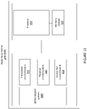
- the network node or radio base station or gNB 800 comprises a processor 810 or processing circuit or a processing module or a processor or means 810; a receiver circuit or receiver module 840; a transmitter circuit or transmitter module 850; a memory module 820 a transceiver circuit or transceiver module 830 which may include the transmitter circuit 850 and the receiver circuit 840.
- the network node 800 further comprises an antenna system 860 which includes antenna circuitry for transmitting and receiving signals to/from at least the UE.
- the antenna system employs beamforming as previously described.
- the network node 500 may belong to any radio access technology including 2G, 3G, 4G or LTE, LTE-A, 5G, WLAN, and WiMax etc. that support beamforming technology.
- the processing module/circuit 810 includes a processor, microprocessor, an application specific integrated circuit (ASIC), field programmable gate array (FPGA), or the like, and may be referred to as the "processor 810.”
- the processor 810 controls the operation of the network node 800 and its components.
- Memory (circuit or module) 820 includes a random access memory (RAM), a read only memory (ROM), and/or another type of memory to store data and instructions that may be used by processor 810.
- RAM random access memory
- ROM read only memory
- the network node 800 in one or more embodiments includes fixed or programmed circuitry that is configured to carry out the operations in any of the embodiments disclosed herein.
- the network node 800 includes a microprocessor, microcontroller, DSP, ASIC, FPGA, or other processing circuitry that is configured to execute computer program instructions from a computer program stored in a non-transitory computer-readable medium that is in, or is accessible to the processing circuitry.
- non-transitory does not necessarily mean permanent or unchanging storage, and may include storage in working or volatile memory, but the term does connote storage of at least some persistence.
- the execution of the program instructions specially adapts or configures the processing circuitry to carry out the operations disclosed herein including anyone of method steps already described.
- the network node 800 may comprise additional components not shown in Figure 13 .
- some embodiments herein include a UE for providing efficient feedback reporting for at least a New Radio-(NR) based wireless communication network system, which feedback includes Channel State Information (CSI).
- CSI Channel State Information
- the UE 900 comprises a processor 910 or processing circuit or a processing module or a processor or means 910; a receiver circuit or receiver module 940; a transmitter circuit or transmitter module 950; a memory module 920 a transceiver circuit or transceiver module 930 which may include the transmitter circuit 950 and the receiver circuit 940.
- the UE 900 further comprises an antenna system 960 which includes antenna circuitry for transmitting and receiving signals to/from at least the UE.
- the antenna system employs beamforming as previously described.
- the network node 500 may belong to any radio access technology including 2G, 3G, 4G or LTE, LTE-A, 5G, WLAN, and WiMax etc. that support beamforming technology.
- the processing module/circuit 910 includes a processor, microprocessor, an application specific integrated circuit (ASIC), field programmable gate array (FPGA), or the like, and may be referred to as the "processor 910.”
- the processor 910 controls the operation of the network node 900 and its components.
- Memory (circuit or module) 920 includes a random access memory (RAM), a read only memory (ROM), and/or another type of memory to store data and instructions that may be used by processor 910.
- RAM random access memory
- ROM read only memory
- the UE 900 in one or more embodiments includes fixed or programmed circuitry that is configured to carry out the operations in any of the embodiments disclosed herein.
- the UE 900 includes a microprocessor, microcontroller, DSP, ASIC, FPGA, or other processing circuitry that is configured to execute computer program instructions from a computer program stored in a non-transitory computer-readable medium that is in, or is accessible to the processing circuitry.
- non-transitory does not necessarily mean permanent or unchanging storage, and may include storage in working or volatile memory, but the term does connote storage of at least some persistence.
- the execution of the program instructions specially adapts or configures the processing circuitry to carry out the operations disclosed herein including anyone of method steps already described. Further, it will be appreciated that the UE 900 may comprise additional components not shown in Figure 14 .
- the UE is configured with a single delay/delay vector for the first beam (leading beam), N 1 delays/delay vectors for the second beam and N 2 delays/delay vectors for the (U- 1 )-th beam and the number of delays/delay vectors may increase with the beam index.
- the UE may report for each beam or for each beam group a delay indicator for the D u l delay vectors selected from the second codebook to the gNB.
- the delay indicator may refer to a set of indices where each index is associated with a delay vector from the second codebook.
- the UE is configured to select for each beam the delay vectors from a "common" set of non-identical delay vectors and to report only a single delay indicator.
- the number of delay vectors in the common set is not greater than max D u l , ⁇ u .
- the UE may therefore report only a single delay indicator instead of multiple delay indicators where the single delay indicator refers to the indices of the delay vectors from the common set.
- the delay vectors associated with the i- th beam may be identical with a subset of the delay vectors associated with the ( i + n )-th beam ( n ⁇ 1).
- the UE then reports only the D U ⁇ 1 l indices associated with the delay vectors of the ( U - 1 ) -th beam to the gNB.
- the UE may be configured to report the indices of the selected delay vectors from the common set in a sorted way such that the gNB may associate the selected delay vectors from the common set to each beam.
- the information on the sorting is either known or reported to the gNB.
- the UE may sort the delay indices with respect to the power/amplitude of the associated combining coefficients over the beams in a decreasing order. The first index in the report may then correspond to the strongest delay (i.e., the delay associated with the combining coefficients having the highest power/amplitude).
- Fig. 1 to Fig. 4 Examples of some delay configurations and reporting of the single delay indicator are shown in Fig. 1 to Fig. 4 .
- the UE may be configured not to report the single delay indicator or multiple delay indicators to the gNB. In such a case, the UE and gNB know a priori the set of delay vectors from the second codebook.
- the UE is configured to report the delay indicator for the selected delay vectors from the second codebook.
- the DFT/DCT delay vectors in the codebook may be grouped into O 2 orthogonal subgroups/submatrices, where each DFT/DCT delay vector in a subgroup may be associated with an index. For example, when there O 2 N 3 delay vectors in the second codebook, there are O 2 subgroups/submatrices, where the first delay vector in a subgroup/submatrix may be associated with a first index ("0"), second delay vector is associated with a second index ("1"), and the last delay vector is associated with the index (" N 3 - 1").
- the UE may be configured to select T delay vectors out of a subgroup of O 2 subgroups/submatrices from the second codebook.
- the UE may then report the group index (0,1, ..., O 2 - 1) and the associated indices for the selected T delay vectors within the selected subgroup. Therefore, for reporting the selected delay vectors and subgroup index, T ⁇ log 2 ( N 3 ) ⁇ + log 2 ( O 2 ) feedback bits are required.
- each delay vector in a subgroup directly with a single bit of an N 3 -length bitmap and to report the bitmap instead of reporting the indices of the delay vectors.
- the number of feedback bits then accounts to N 3 bits for reporting the bitmap and log 2 ( O 2 ) bits for the subgroup indication.
- the UE is configured to report the group index (0,1, ..., O 2 - 1), e.g., by higher layer (RRC) and not to report the indices of the T selected DFT/DCT delay vectors.
- RRC higher layer
- the UE is configured to the report the indices of the T selected DFT/DCT delay vectors, e.g., by higher layer (RRC) and not to report the group index.
- RRC higher layer
- the UE may indicate the selected delay vectors associated with the non-zero combining coefficients per beam, or K selected combining coefficients (corresponding to the coefficients with the highest amplitude/power) for the 2U beams in the report.
- the delay vectors of each beam are associated with a D u l ⁇ length bitmap, where D u l is the number of configured delay vectors of the u -th beam.
- Each bit in the bitmap is associated with a single delay of the max D u l , ⁇ u common delay vectors.
- the first bit may be associated with the first common delay vector, the second bit with the second common delay vector and so on.
- the UE report then contains for the u-th beam a length ⁇ D u l bitmap for indicating the selected delay vectors associated with the non-zero combining coefficients or the K selected combining coefficients.
- a delay/delay vector is common to all beams and is associated with only zero-valued combining coefficients, the corresponding combining coefficients are not reported and not indicated by the bitmap.
- the corresponding index is removed from the delay indicator reported to the gNB.
- the corresponding combining coefficients are not reported and not indicated by the bitmap. For example, when the u-th beam is only associated with zero-valued combining coefficients, the D u l ⁇ length bitmap associated with the u-th beam and the corresponding combining coefficients are not reported.
- the UE is configured to receive from the gNB the higher layer (RRC or MAC-CE) or physical layer parameters D u l for the U beams and L transmission layers, where the number of delay vectors D u l may be different, identical or partially identical over the beams.
- RRC Radio Resource Control
- MAC-CE physical layer parameters
- the number of delays may increase (decrease) with the beam or subgroup beam index in a known manner, it is sufficient to signal only a subset of the parameters D u l or none of the parameters D u l for the delay configuration of the precoder matrix.
- the gNB may not signal the parameters D u l .
- the gNB may signal the single parameter D U ⁇ 1 l for the delay configuration of the precoder matrix.
- the gNB may signal the two parameters D 0 l and D U ⁇ 1 l for the delay configuration of the precoder matrix.
- the gNB may signal the two parameters D 1 l and D U ⁇ 1 l for the delay configuration of the precoder matrix.
- the gNB may signal the single parameter D ( l ) for the delay configuration of the precoder matrix.
- the UE is configured to select and to report the parameters D u l for the U beams and L transmission layers to the gNB.
- the number of delays may increase (decrease) with the beam or subgroup beam index in a known manner, it is sufficient to report only a subset of the parameters D u l or none of the parameters D u l for the delay configuration of the precoder matrix.
- the UE is configured to use a priori known parameters D u l for the delay configuration of the precoder matrix.
- the UE is configured with at least one delay vector for the leading beam where the first delay vector for the leading beam is identical to the first delay vector from the selected subgroup/submatrix out of the O2 subgroups/submatrices from the second codebook.
- the leading beam is associated with the strongest combining coefficient (which corresponds to the coefficient having the largest power/amplitude over all combining coefficients).
- the UE is configured not to report the index associated with the first delay vector of the leading beam. This means, the UE is configured to remove the index associated with the first delay vector of the leading beam from the delay indicator, i.e., the index associated with the first delay vector associated with the leading beam is not reported.
- the UE is configured to normalize the selected delays vectors with respect to a single reference delay vector. This means, the corresponding delays in the time/delay domain of the delay vectors are subtracted from a single reference delay.
- the reference delay vector may be identical with the first delay vector of the leading beam.
- the reference delay vector is known at the gNB and hence the associated delay index is not reported to the gNB.
- the UE is configured to select the delays/delay vectors per beam and layer from a subset of the delay vectors from the second codebook.
- the number of delay vectors and the specific delay vectors in the subset are associated with the delay values of the MIMO channel impulse response(s) (CIR(s)) between the UE and gNB.
- CIR(s) MIMO channel impulse response(s)
- the average delay spread of the MIMO channel is small (which is typically observed in Line-of-sight (LOS) channel(s))
- LOS Line-of-sight
- the UE selects only few delay vectors from a second codebook, where the corresponding delays of the selected delay vectors are associated with the dominant channel delays of the MIMO CIR.
- the average delay spread of the channel impulse response is large (as observed in Non-Line-of-sight (NLOS) channel(s))
- NLOS Non-Line-of-sight
- the energy of the channel impulse response is concentrated in a one or more peaks and a larger number of dominant channel delays is associated with the peak(s) of the CIR.
- the UE selects a larger number of delay vectors from the second codebook. Therefore, for typical MIMO channel settings, the selected delay vectors by the UE are mainly associated with a subset of the delay vectors from the second codebook. Therefore, the size of the second codebook may be reduced, and thus the computational complexity for selecting the delay vectors by the UE.
- the UE is configured to select the delay vectors from a subset of the second codebook where the subset is defined by the first Z 1 vectors and the last Z 2 vectors of a DFT matrix.
- the UE is configured to select the delay vectors from multiple subsets of the second codebook.
- the DFT/DCT delay vectors in the codebook may be grouped into O 2 orthogonal subgroups/submatrices, where each DFT/DCT delay vector in a subgroup may be associated with an index. For example, when there O 2 N 3 delay vectors in the second codebook, there are O 2 subgroups/submatrices, where the first delay vector in a subgroup/submatrix may be associated with a first index ("0"), second delay vector is associated with a second index ("1"), and the last delay vector is associated with the index (" N 3 - 1").
- the UE is configured to select the delay vectors from a subset of orthogonal DFT vectors from the subgroup.
- the subset associated with a subgroup may be defined by the first Z delay vectors of the subgroup.
- the subset associated with a subgroup may be defined by the first Z 1 delay vectors and the last delay Z 2 vectors of the orthogonal delay vectors of the subgroup.
- the subset associated with a subgroup may also be defined by the i 1 :i 2 orthogonal delay vectors in the subgroup.
- the subset associated with a subgroup may also be defined by the i 1 :i 2 orthogonal delay vectors and the i 3 :i 4 orthogonal delay vectors in the subgroup.
- the UE is either configured by the gNB with a subset of delay vectors from the second codebook by higher layer (such as Radio Resource Control (RRC) layer or MAC-CE) or physical layer, or with a priori known (default) subset(s) of delay vectors from the second codebook, or to report the selected subset(s) of delay vectors to the gNB.
- RRC Radio Resource Control
- MAC-CE Radio Resource Control
- the UE is configured by the gNB with the higher layer (such as Radio Resource Control (RRC) layer or MAC-CE) or physical layer parameter(s) Z or Z 1 and Z 2 that indicate the subset of delay vectors (from a subgroup of O 2 orthogonal subgroups/submatrices) from the second codebook, or with a priori known (default) parameter(s) Z or Z 1 and Z 2 that indicate the subset of delay vectors (from a subgroup of O 2 orthogonal subgroups/submatrices) from the second codebook, or to report parameter(s) Z or Z 1 and Z 2 that indicate the selected subset of delay vectors (from a subgroup of O 2 orthogonal subgroups/submatrices) from the second codebook.
- RRC Radio Resource Control
- MAC-CE physical layer parameter(s) Z or Z 1 and Z 2 that indicate the subset of delay vectors (from a subgroup of O 2 orthogonal subgroups/submatrices) from the second codebook
- RRC
- the UE is configured to report a bitmap to indicate the selected delay vectors of the subset from the second codebook.
- the length of the bitmap is given by the size of the subset. A "1" in the bitmap may indicate that the corresponding delay vector of the subset is selected, and a "0" in the bitmap may indicate that the corresponding delay vector is not selected.
- the UE may be configured to select the delay vectors for one layer or a for set of layers from one subgroup out of the O 2 orthogonal subgroups/submatrices from the second codebook and for others layers from a different subgroup out of the O 2 orthogonal subgroups/submatrices from the second codebook.
- the UE may be configured to select a first set of delay vectors for one layer or for a set of layers from one subgroup out of the O 2 orthogonal subgroups/submatrices from the second codebook and for other layers a second set of delay vectors from the same subgroup, where the first and second set of delay vectors are orthogonal to each other.
- the UE is configured to select a first set of delay vectors for a first set of layer(s) from one subgroup out of the O 2 orthogonal subgroups/submatrices from the second codebook and for a different second set of layer(s) a second set of delay vectors from the same subgroup, where the first and second set of delay vectors are partially orthogonal to each other.
- the UE is configured to select N delay vectors for the first set of layer(s) and M delay vectors for the second set of layer(s) and out of two sets of selected delay vectors at least G delay vectors are orthogonal to each other.
- the UE is configured to select an identical number of delay vectors for both sets of layers and at least G delay vectors are orthogonal to each other.
- the parameter G may be configured by the gNB, or reported by the UE, or fixed and known at the UE.
- the UE is configured to select N delay vectors from the second codebook, where N ' out of N delay vectors are fixed and a priori known at the UE.
- the delay indicator reported to the gNB then refers only to (N-N) indices instead of N indices that correspond to the selected non-fixed delay vectors by the UE.
- the coefficient c l,p,j is a real-valued coefficient representing a common amplitude across all combining coefficients associated with the j -th delay vector and l -th layer and may be polarization-dependent or not. In the case that c l,p,j is polarization-dependent, c l,p,j represents a common amplitude across all combining coefficients associated with the j -th delay vector, l -th layer and p -th polarization.
- c l,p,j is polarization-independent
- a l,p,i , b l,p,i,j , c l,p,j are referred to as amplitudes or power of the combining coefficients, and d l,p,i,j is referred to as phase of the combining coefficient.
- the UE may be configured to represent the combining coefficients or only a set of the combining coefficients either by scheme 1, scheme 2, scheme 3, or scheme 4.
- the schemes may also be combined for representing the combining coefficients such that for one part of the combining coefficients one scheme is used and for another part of the combining coefficients another scheme is used.
- the UE may be configured to select one quantization scheme out of the above quantization schemes and to quantize and report the combining coefficients using the selected scheme.
- the UE is configured to select the quantization scheme out of the schemes 2 and 3.
- scheme 2 is used for quantization and reporting of the combining coefficients.
- scheme 3 is used for the quantization and reporting of the combining coefficients.
- the UE may be configured to receive the quantization parameter for selecting the quantization (e.g., scheme 2 or 3) of the combining coefficients from the gNB via the higher layer (RRC or MAC-CE) or physical layer (L1) parameter (DCI).
- the quantization parameter for selecting the quantization e.g., scheme 2 or 3
- RRC or MAC-CE higher layer
- L1 physical layer
- the UE may be configured to select the quantization scheme (e.g., scheme 2 or 3) based on the number of reported beam indices and indices of delays/delay vectors (example see above) and to indicate in the CSI report the selected quantization scheme by higher layer (RRC) or physical layer (UCI).
- the quantization scheme e.g., scheme 2 or 3
- RRC higher layer
- UCI physical layer
- the UE may be configured to select the quantization scheme (e.g., scheme 2 or 3) based on the number of beams and delays (example see above) to be reported and not to indicate in the CSI report the selected quantization scheme. Based on the number of reported beam indices and indices for the delays/delay vectors, the UE implicitly indicates to the gNB the quantization scheme selected by the UE.
- the quantization scheme e.g., scheme 2 or 3
- a l,p,i , B l,pi,j , C l,p,j and D l,p,i,j be the number of bits to quantize a l,p,i , b l,p,i,j , c l,p,j and d l,p,i,j , respectively.
- the combining coefficients for the L transmission layers are quantized according to at least one of the following alternatives.
- a l ( C l ) and/or B l are either known and fixed at the UE, or configured via RRC signaling, or the UE reports them as a part of the CSI report, where A l ( C l ) and/or B l may be different, identical for a subset of layers, or identical for all layers.
- the quantization of the amplitudes a l,p,i ( c l,p,j ) is not identical for the combining coefficients of a layer.
- the quantization of the amplitudes b l,p,i,j is not identical for the combining coefficients per layer.
- B l,i,j B l,p,i,j is identical for both polarizations and depends on the beam, delay and layer index.
- the parameters B l,j , B l,i , or B l,i,j are either known at the UE, configured via RRC signaling, or the UE may report them as a part of the CSI report.
- the amplitudes a l,p,i ( c l,p,j ) and/or b l,p,i,j are partitioned each into at least two disjoint subsets, and each subset is assigned a single and different value for the amplitude quantization.
- the number of sets is two, where each set contains the amplitudes with respect to a single polarization.
- the number of sets for a l,p,i ( c l,p,j ) is two, where the first set contains X amplitudes that correspond to the strongest/highest amplitudes, and the second set contains the remaining amplitudes.
- the amplitudes of the first set may be quantized with N E ⁇ 2,3,4 ⁇ bits and the amplitudes of the second set with M ⁇ ⁇ 1,2,3 ⁇ bits.
- the number of sets for a l,p,i ( c l,p,j ) is two, where the first set contains the strongest amplitude, and the second set contains the remaining amplitudes.
- the number of sets for b l,p,i,j is two, where the first set contains all amplitudes b l,p,i,j that correspond to the indices of the X strongest/highest amplitudes a l,p,i , and the second set contains the remaining amplitudes.
- the number of sets for b l,p,i,j is two, where the first set contains all amplitudes b l,p,i,j that correspond to the indices of the X strongest/highest amplitudes c l,p,j , and the second set contains the remaining amplitudes.
- the parameter X may be a higher layer parameter and known at the UE, configured by the gNB, or reported by the UE.
- the number of sets for b l,p,i,j is two, where the first set contains all amplitudes b l,p,i,j with indices ( p,i,j ) that correspond to the indices of the X strongest/highest amplitudes a l,p,i ⁇ c l,p,j , and the second set contains the remaining amplitudes.
- the number of sets for b l,p,i,j is two, where the first set contains all amplitudes b l,p,i,j with indices ( p,i,j ) that correspond to the indices of the X 1 strongest/highest amplitudes a l,p,i and of the X 2 strongest/highest amplitudes c l,p,j , and the second set contains the remaining amplitudes.
- the amplitudes of the first set may be quantized with N E ⁇ 1,2,3,4 ⁇ bits and the amplitudes of the second set with M ⁇ ⁇ 0,1,2,3 ⁇ bits.
- the parameter(s) X 1 and X 2 may be higher layer parameters and known at the UE, configured by the gNB, or reported by the UE.
- the single value is either known and fixed at the UE, or configured via RRC signaling, or the UE reports them as a part of the CSI report, where the single value may be different, identical for a subset of layers, or identical for all layers.
- the quantization of the phases d l,p,i,j is not identical for the combining coefficients of a layer.
- D l,i,j D l,p,i,j is identical for both polarizations and depends only on the beam, delay and layer index.
- the phases d l,p,i,j are partitioned into at least two disjoint subsets (per layer), and each subset is assigned a single and different value for the phase quantization.
- the number of sets is two, where each set contains the phases with respect to a single polarization.
- the first set contains the phases corresponding to the X strongest/highest amplitudes a l,p,i ( c l,p,j ), and the second set contains the phases corresponding to the remaining (weaker) amplitudes.
- the first set contains the phases corresponding to the X strongest/highest amplitudes a l,p,i b l,p,i,j (or c l,p,j b l,p,i,j ) and the second set contains the remaining phases.
- the first set contains the phases corresponding to the X strongest/highest amplitudes a l,p,i c l,p,j and the second set the remaining phases.
- the first set contains the phases corresponding to the X strongest/highest amplitudes a l,p,i b i,p,i,j c l,p,j , and the second set contains the remaining phases.
- the phases d l,p,i,j of the first set may be quantized with N bits and the phases of the second set with M bits.
- Examples of ( N,M ) are (4,3), (4,2), (4,1), (4,0), (3,2), (3,1), (3,0), (2,1), (2,0).
- the parameters X , X 1 , and X 2 may be either known at the UE, selected and reported by the UE, or configured by the gNB.
- the phases d l,p,i,j are partitioned into at least three disjoint subsets (per layer), and each subset is assigned a single and different value for the phase quantization.
- the first set contains the phases corresponding to the X 1 first strongest/highest amplitudes a l,p,i (or c l,p,j )
- the second set contains the phases corresponding to the X 2 second strongest/highest amplitudes a l,p,i (or c l,p,j )
- the third set contains the remaining amplitudes.
- the first set contains the phases corresponding to the X 1 strongest/highest amplitudes a l,p,i b l,p,i,j (or c l,p,j b l,p,i,j )
- the second set contains the phases corresponding to the X 2 second strongest/highest amplitudes a l,p,i b l,p,i,j (or c l,p,j b l,p,i,j )
- the third set contains the remaining amplitudes.
- the parameters X 1 and X 2 may be either known at the UE, selected and reported by the UE, or configured by the gNB.
- Examples of ( N,M,V ) are: (4,3,2), (4,3,1), (4,3,0), (4,2,1), (4,2,0), (4,1,0), (3,2,1), (3,2,0), (3,1,0)
- the UE is configured to partition the amplitudes b l,p,i,j into at least two disjoint subsets possibly per layer, and each subset is assigned a single value for the quantization of the amplitudes.
- the amplitudes are partitioned into two sets where the first set contains the amplitudes corresponding to K selected combining coefficients and the second set contains the remaining amplitudes corresponding to the remaining coefficients.
- the amplitudes of the first set may correspond to the K strongest combining coefficients (i.e., the combining coefficients having the highest amplitude/power over all combining coefficients) and the second set may contain the amplitudes corresponding to the set of the remaining coefficients.
- the UE may report a bitmap, where each bit is associated with an amplitude b l,p,i,j .
- a "1" in the bitmap may indicate that the corresponding amplitude of the combining coefficient is reported and a "0" may indicate that the corresponding amplitude is not reported.
- the bitmap may therefore contain K or less than K "1".
- the bitmap used for indicating the selected delay vectors per beam (see above) is identical with the bitmap used for reporting the amplitudes b l,p,i,j , and hence it may not be reported.
- the higher layer parameter K may be known at the UE, configured by the gNB, or reported by the UE.
- the parameter K may be identical for a subset of the layers.
- the quantized amplitudes b ⁇ l,p,i,j represent a bitmap which is identical to the bitmap for indicating the selected delays of the delay indicator (see above). In this case, the bitmap for indicating the selected delays of the delay indicator may not be reported.
- the UE is configured to partition the phases d l,p,i,j into at least two disjoint subsets (per layer), and each subset is assigned a single value for phase quantization.
- the number of sets for d l,p,i,j is two, where the first set contains the phases corresponding to the K selected combining coefficients (indicated by the bitmap) and the second set contains the remaining phases.
- the reported phases from the first set are indicated by the same bitmap used for the indication of the amplitudes b l , p , i,j .
- the UE is configured to partition the phases d l,p,i,j into at least three disjoint subsets (per layer), and each subset is assigned a single value for phase quantization.
- the first set contains the phases corresponding to the K 1 strongest combining coefficients
- the second set contains the phases corresponding to the K 2 strongest combining coefficients
- the third set contains the remaining phases.
- the phases of the first set may be quantized with N ( N ⁇ ⁇ 2,3,4 ⁇ ) bits
- the phases of the second set with M ( M E ⁇ 1,2,3 ⁇ ) bits
- V V E ⁇ 0,1 ⁇
- the higher layer parameters K 1 and K 2 may be known at the UE, configured by the gNB, or reported by the UE.
- the UE is configured to normalize the combining coefficients with respect to the strongest combining coefficient (corresponding to coefficient associated with the largest amplitude) in amplitude and phase such that the strongest combining coefficient is given by the value one.
- the amplitude(s) a l,p,i (and/or c l,p , j ) to be reported are sorted with respect to the strongest/largest amplitude. For example, the amplitudes a l,p,i are sorted such that the strongest amplitude a l ,1,0 is associated with the leading beam and the first beam index and the first polarization. Similarly, the amplitudes c l,p,j are sorted such that the strongest amplitude c l, 1,0 is associated with the first polarization and first delay.
- the amplitude(s) a l,p,i (and/or c l,p,j ) to be reported are sorted and normalized such that the strongest amplitude is a l ,1,0 (and/or c l ,1,0 ) and not reported.
- the word "comprise” or “comprising” has been used in a non-limiting sense, i.e. meaning “consist at least of”. Although specific terms may be employed herein, they are used in a generic and descriptive sense only and not for purposes of limitation.
- the embodiments herein may be applied in any wireless systems including GSM, 3G or WCDMA, LTE or 4G, LTE-A (or LTE-Advanced), 5G, WiMAX, WiFi, satellite communications, TV broadcasting etc. that may employ beamforming technology.
Landscapes
- Engineering & Computer Science (AREA)
- Computer Networks & Wireless Communication (AREA)
- Signal Processing (AREA)
- Physics & Mathematics (AREA)
- Mathematical Physics (AREA)
- Power Engineering (AREA)
- Radio Transmission System (AREA)
- Mobile Radio Communication Systems (AREA)
- Monitoring And Testing Of Transmission In General (AREA)
- Transmitters (AREA)
Claims (23)
- Procédé exécuté par un équipement utilisateur, UE, le procédé comprenant les étapes suivantes :- recevoir, à partir d'un nœud de réseau, un signal radio par l'intermédiaire d'un canal à entrées multiples/sorties multiples, MIMO, où le signal radio contient au moins un signal de référence de liaison descendante, DL, selon une configuration de signal de référence DL ;- estimer ledit canal MIMO sur la base dudit au moins un signal de référence DL reçu pour des blocs de ressources configurés ;- calculer une matrice de précodage pour un certain nombre de ports d'antenne du nœud de réseau et de sous-bandes configurées ; la matrice de précodage étant basée sur un premier livre de codes et sur un second livre de codes et un ensemble de coefficients de combinaison pour la mise à l'échelle/combinaison complexe d'un ou plusieurs vecteurs sélectionnés à partir du premier livre de codes et du second livre de codes, où le premier livre de codes contient une ou plusieurs composantes/vecteurs de faisceau spatial côté émission de la matrice de précodage et le second livre de codes contient une ou plusieurs composantes/vecteurs de retard de la matrice de précodage ;- quantifier les coefficients de combinaison par faisceau de la matrice de précodage, où chaque coefficient de combinaison


 - rendre compte, au nœud de réseau, un retour d'informations d'état de canal, CSI, et/ou un indicateur de matrice de précodage, PMI, et/ou un indicateur de rang/PMI, PMI/RI, utilisé pour indiquer la matrice de précodage pour les ports d'antenne et les sous-bandes configurés, où le rapport contient un bitmap pour indiquer au moins des vecteurs de retard sélectionnés et des vecteurs de faisceau spatial associés à des coefficients de combinaison non nuls dudit ensemble de coefficients de combinaison quantifiés inclus dans le rapport transmis au nœud de réseau.
 - Procédé selon la revendication 1, dans lequel la matrice de précodage,


- Procédé selon la revendication 1 ou la revendication 2, comprenant en outre de recevoir, depuis ledit nœud de réseau, un paramètre de couche supérieure K indiquant un nombre maximum de coefficients de combinaison non nuls à rapporter par l'UE, par couche, et où le bitmap contient un nombre K, ou inférieur à K, de « 1 » par couche.
- Procédé selon l'une quelconque des revendications 1 à 3, comprenant de sélectionner, pour chaque vecteur de retard de faisceau d'un ensemble commun de D(l) vecteurs de retard non identiques sélectionnés par l'UE à partir du second livre de codes, et de rapporter audit nœud de réseau un indicateur de retard unique indiquant les vecteurs de retard non identiques sélectionnés de l'ensemble commun.
- Procédé selon la revendication 4 comprenant de sélectionner de D(l) vecteurs de retard à partir du second livre de codes pour l'ensemble commun, où N des D(l) retards sont fixes et connus de l'UE et du nœud de réseau, et où D(l) - N retards sélectionnés sont indiqués par l'indicateur de retard.
- Procédé selon l'une quelconque des revendications 1 à 5, dans lequel un faisceau associé à un coefficient de combinaison ayant la plus grande amplitude parmi tous les coefficients de combinaison est le faisceau leader, et le procédé comprend en outre de soustraire un retard de référence, qui est identique au premier retard associé au faisceau leader, des retards sélectionnés de l'ensemble commun.
- Procédé selon la revendication 6, comprenant de ne pas rapporter un indice associé à un premier vecteur de retard du faisceau leader en supprimant l'indice associé au premier vecteur de retard de l'indicateur de retard.
- Procédé selon la revendication 1 ou la revendication 2 comprenant de sélectionner des vecteurs de retard par faisceau et par couche à partir d'un sous-ensemble de vecteurs de retard du second livre de codes.
- Procédé selon la revendication 8, dans lequel l'UE est configuré avec le sous-ensemble de vecteurs de retard du second livre de codes par une signalisation de couche supérieure ou avec un sous-ensemble connu à l'avance de vecteurs de retard du second livre de codes.
- Procédé exécuté par un équipement utilisateur, UE, le procédé comprenant les étapes suivantes :- recevoir, d'un nœud de réseau, un signal radio par l'intermédiaire d'un canal à entrées multiples/sorties multiples, MIMO, où le signal radio contient au moins un signal de référence de liaison descendante, DL, selon une configuration de signal de référence DL ;- estimer ledit canal MIMO sur la base dudit au moins un signal de référence DL reçu pour des blocs de ressources configurés ;- calculer une matrice de précodage pour un certain nombre de ports d'antenne du nœud de réseau et de sous-bandes configurées ; la matrice de précodage étant basée sur un premier livre de codes et sur un second livre de codes et un ensemble de coefficients de combinaison pour la mise à l'échelle/combinaison complexe d'un ou plusieurs vecteurs sélectionnés à partir du premier livre de codes et du second livre de codes, où le premier livre de codes contient une ou plusieurs composantes et/ou un ou plusieurs vecteurs de faisceau spatial côté émission de la matrice de précodage et le second livre de codes contient une ou plusieurs composantes et/ou un ou plusieurs vecteurs de retard de la matrice de précodage ;- quantifier les coefficients de combinaison par faisceau de la matrice de précodage, où chaque coefficient de combinaison


 - rendre compte, au nœud de réseau, un retour d'information d'état de canal, CSI, et/ou un indicateur de matrice de précodage, PMI, et/ou un indicateur de rang/PMI, PMI/RI, utilisé pour indiquer la matrice de précodage pour les ports d'antenne et les sous-bandes configurés, où le rapport contient un bitmap pour indiquer au moins des vecteurs de retard sélectionnés et des vecteurs de faisceau spatial associés à des coefficients de combinaison non nuls dudit ensemble de coefficients de combinaison quantifiés inclus dans le rapport transmis au nœud de réseau.
 - Procédé selon la revendication 1, dans lequel les amplitudes a l,p,i du premier sous-ensemble contiennent l'amplitude la plus forte et sont quantifiées avec 0 bit et ne sont pas rapportées, et les amplitudes a l,p,i du second sous-ensemble sont quantifiées avec N = 1 ou 2 ou 3 ou 4 bits et sont rapportées.
- Procédé selon la revendication 1 ou la revendication 10, comprenant de partitionner les amplitudes b l,p,i,j , par couche, en au moins deux sous-ensembles disjoints par couche, et chaque sous-ensemble se voit attribuer une valeur unique pour la quantification des amplitudes b l,p,i,j .
- Procédé selon la revendication 12, dans lequel le premier sous-ensemble desdits sous-ensembles distincts contient les amplitudes b l,p,i,j correspondant à un nombre inférieur ou égal à K coefficients de combinaison non nuls sélectionnés, indiqués par le bitmap, et le second sous-ensemble contient les coefficients d'amplitude restants.
- Procédé selon la revendication 13, dans lequel les amplitudes du premier sous-ensemble sont quantifiées avec N = 2 ou 3 bits et sont rapportées, et les amplitudes du second sous-ensemble sont quantifiées avec 0 bit et ne sont pas rapportées.
- Procédé selon la revendication 1 ou la revendication 10, comprenant de partitionner les phases dl,p,i,j en au moins deux sous-ensembles disjoints, par couche, et chaque sous-ensemble se voit attribuer une seule valeur pour la quantification de phase.
- Procédé selon la revendication 15, dans lequel le premier sous-ensemble contient les phases correspondant à un nombre inférieur ou égal à K coefficients de combinaison non nuls sélectionnés, indiqués par le bitmap, et le second sous-ensemble contient les phases restantes, et où les phases du premier sous-ensemble sont quantifiées avec N = 2 ou 3 ou 4 bits et sont rapportées, et les phases du second sous-ensemble sont quantifiées avec 0 bit et ne sont pas rapportées.
- Procédé selon la revendication 16, dans lequel le bitmap est utilisé pour indiquer les phases rapportées du premier sous-ensemble et du second sous-ensemble et dans lequel le même bitmap est utilisé pour indiquer les amplitudes b l,p,i,j du premier sous-ensemble et du second ensemble.
- Procédé selon la revendication 1 comprenant de normaliser les amplitudes a l,p,i et de rapporter les amplitudes a l,p,i à l'exception de l'amplitude la plus forte.
- Procédé exécuté par un nœud de réseau, le procédé comprenant les étapes suivantes :- transmettre, à un équipement utilisateur, UE, un signal radio par l'intermédiaire d'un canal à entrées multiples/sorties multiples, MIMO, où le signal radio contient au moins un signal de référence de liaison descendante, DL, selon une configuration de signal de référence DL ; et- recevoir, à partir de l'UE, un rapport comprenant un retour d'informations d'état de canal, CSI, et/ou un indicateur de matrice de précodage, PMI, et/ou un indicateur de rang/PMI, PMI/RI, utilisé pour indiquer une matrice de précodage pour des ports d'antenne configurés et des sous-bandes configurées, la matrice de précodage étant basée sur un premier livre de codes et sur un second livre de codes et un ensemble de coefficients de combinaison pour la mise à l'échelle/combinaison complexe d'un ou plusieurs vecteurs sélectionnés dans le premier livre de codes et le second livre de codes, où le premier livre de codes contient une ou plusieurs composantes et/ou un ou plusieurs vecteurs de faisceau spatial côté émission de la matrice de précodage et le second livre de codes contient une ou plusieurs composantes et/ou un ou plusieurs vecteurs de retard de la matrice de précodage ; etoù le rapport contient un bitmap pour indiquer au moins les vecteurs de retard sélectionnés et les vecteurs de faisceau spatial associés aux coefficients de combinaison non nuls d'un ensemble de coefficients de combinaison quantifiés inclus dans le rapport reçu de l'UE, où les coefficients de combinaison sont quantifiés par l'UE, par faisceau, de la matrice de précodage, où chaque coefficient de combinaison


- Procédé exécuté par un nœud de réseau, le procédé comprenant les étapes suivantes :- transmettre à un équipement utilisateur, UE, un signal radio par l'intermédiaire d'un canal à entrées multiples/sorties multiples, MIMO, où le signal radio contient au moins un signal de référence de liaison descendante, DL, selon une configuration de signal de référence DL ; et- recevoir, à partir de l'UE, un rapport comprenant un retour d'informations d'état de canal, CSI, et/ou un indicateur de matrice de précodage, PMI, et/ou un indicateur de rang/PMI, PMI/RI, utilisé pour indiquer la matrice de précodage pour les ports d'antenne et les sous-bandes configurés, la matrice de précodage étant basée sur un premier livre de codes et sur un second livre de codes et un ensemble de coefficients de combinaison pour une mise à l'échelle/combinaison complexe d'un ou plusieurs vecteurs sélectionnés à partir du premier livre de codes et du second livre de codes, où le premier livre de codes contient une ou plusieurs composantes et/ou un ou plusieurs vecteurs de faisceau spatial côté émission de la matrice de précodage et le second livre de codes contient une ou plusieurs composantes et/ou un ou plusieurs vecteurs de retard de la matrice de précodage ; et- où le rapport contient un bitmap pour indiquer au moins des vecteurs de retard sélectionnés et des vecteurs de faisceau spatial associés à des coefficients de combinaison non nuls d'un ensemble de coefficients de combinaison quantifiés inclus dans le rapport reçu de l'UE, où les coefficients de combinaison sont quantifiés par l'UE, par faisceau de la matrice de précodage, où chaque coefficient de combinaison


- Procédé selon la revendication 19 ou la revendication 20, dans lequel la matrice de précodage,


- Equipement utilisateur, UE, (900) comprenant un processeur (910) et une mémoire (920), ladite mémoire (920) contenant des instructions pouvant être exécutées par ledit processeur (920), moyennant quoi ledit UE est en mesure de réaliser l'un quelconque des points mentionnés dans les revendications de procédé 1 à 18.
- Noeud de réseau (800) comprenant un processeur (810) et une mémoire (820), ladite mémoire (820) contenant des instructions exécutables par ledit processeur (810), moyennant quoi ledit nœud de réseau (800) est en mesure de réaliser l'un quelconque des points mentionnés dans les revendications de procédé 19 à 21.
Priority Applications (1)
| Application Number | Priority Date | Filing Date | Title |
|---|---|---|---|
| EP22208736.3A EP4160933A1 (fr) | 2018-12-22 | 2019-12-13 | Procédés et appareils de rapport de rétroaction dans un réseau de communication sans fil |
Applications Claiming Priority (2)
| Application Number | Priority Date | Filing Date | Title |
|---|---|---|---|
| EP18215815.4A EP3672096A1 (fr) | 2018-12-22 | 2018-12-22 | Procédés et appareils de communication d'informations de retour dans un réseau de communications sans fil |
| PCT/EP2019/085074 WO2020126905A1 (fr) | 2018-12-22 | 2019-12-13 | Procédés et appareils de notification d'informations en retour dans un réseau de communication sans fil |
Related Child Applications (1)
| Application Number | Title | Priority Date | Filing Date |
|---|---|---|---|
| EP22208736.3A Division EP4160933A1 (fr) | 2018-12-22 | 2019-12-13 | Procédés et appareils de rapport de rétroaction dans un réseau de communication sans fil |
Publications (2)
| Publication Number | Publication Date |
|---|---|
| EP3900207A1 EP3900207A1 (fr) | 2021-10-27 |
| EP3900207B1 true EP3900207B1 (fr) | 2022-11-23 |
Family
ID=65685089
Family Applications (7)
| Application Number | Title | Priority Date | Filing Date |
|---|---|---|---|
| EP18215815.4A Withdrawn EP3672096A1 (fr) | 2018-12-22 | 2018-12-22 | Procédés et appareils de communication d'informations de retour dans un réseau de communications sans fil |
| EP19155102.7A Withdrawn EP3672099A1 (fr) | 2018-12-22 | 2019-02-01 | Procédés et appareils de restriction de livre de codes pour communication d'informations de retour de type-ii dans un réseau de communications sans fil |
| EP19164947.4A Withdrawn EP3672100A1 (fr) | 2018-12-22 | 2019-03-25 | Procédés et appareils de restriction de livres de codes pour communication d'informations de retour de type-ii et configuration de couche supérieure et élaboration de rapports de livres de codes à combinaison linéaire dans un réseau de communications sans fil |
| EP19816795.9A Active EP3900207B1 (fr) | 2018-12-22 | 2019-12-13 | Procédés et appareils de communication d'informations de retour dans un réseau de communications sans fil |
| EP22208736.3A Pending EP4160933A1 (fr) | 2018-12-22 | 2019-12-13 | Procédés et appareils de rapport de rétroaction dans un réseau de communication sans fil |
| EP23196893.4A Pending EP4283882A3 (fr) | 2018-12-22 | 2019-12-16 | Procédés et appareils de restriction de livre de codes pour rapport de rétroaction de type ii et configuration de couche supérieure |
| EP19817736.2A Active EP3900208B1 (fr) | 2018-12-22 | 2019-12-16 | Procédés et appareils de restriction de livres de codes pour communication d'informations de retour de type-ii et configuration de couche supérieure et élaboration de rapports de livres de codes à combinaison linéaire dans un réseau de communications sans fil |
Family Applications Before (3)
| Application Number | Title | Priority Date | Filing Date |
|---|---|---|---|
| EP18215815.4A Withdrawn EP3672096A1 (fr) | 2018-12-22 | 2018-12-22 | Procédés et appareils de communication d'informations de retour dans un réseau de communications sans fil |
| EP19155102.7A Withdrawn EP3672099A1 (fr) | 2018-12-22 | 2019-02-01 | Procédés et appareils de restriction de livre de codes pour communication d'informations de retour de type-ii dans un réseau de communications sans fil |
| EP19164947.4A Withdrawn EP3672100A1 (fr) | 2018-12-22 | 2019-03-25 | Procédés et appareils de restriction de livres de codes pour communication d'informations de retour de type-ii et configuration de couche supérieure et élaboration de rapports de livres de codes à combinaison linéaire dans un réseau de communications sans fil |
Family Applications After (3)
| Application Number | Title | Priority Date | Filing Date |
|---|---|---|---|
| EP22208736.3A Pending EP4160933A1 (fr) | 2018-12-22 | 2019-12-13 | Procédés et appareils de rapport de rétroaction dans un réseau de communication sans fil |
| EP23196893.4A Pending EP4283882A3 (fr) | 2018-12-22 | 2019-12-16 | Procédés et appareils de restriction de livre de codes pour rapport de rétroaction de type ii et configuration de couche supérieure |
| EP19817736.2A Active EP3900208B1 (fr) | 2018-12-22 | 2019-12-16 | Procédés et appareils de restriction de livres de codes pour communication d'informations de retour de type-ii et configuration de couche supérieure et élaboration de rapports de livres de codes à combinaison linéaire dans un réseau de communications sans fil |
Country Status (8)
| Country | Link |
|---|---|
| US (3) | US11632154B2 (fr) |
| EP (7) | EP3672096A1 (fr) |
| JP (2) | JP7450625B2 (fr) |
| KR (3) | KR20210106548A (fr) |
| CN (2) | CN113228527A (fr) |
| ES (2) | ES2937396T3 (fr) |
| PL (1) | PL3900207T3 (fr) |
| WO (2) | WO2020126905A1 (fr) |
Families Citing this family (14)
| Publication number | Priority date | Publication date | Assignee | Title |
|---|---|---|---|---|
| WO2020122793A1 (fr) * | 2018-12-12 | 2020-06-18 | Telefonaktiebolaget Lm Ericsson (Publ) | Communication de coefficients pour des informations d'état de canal |
| WO2020164083A1 (fr) * | 2019-02-15 | 2020-08-20 | Zte Corporation | Rétroaction d'informations d'état de canal dans une communication sans fil |
| US10985823B2 (en) * | 2019-03-15 | 2021-04-20 | Samsung Electronics Co., Ltd. | Method and apparatus for codebook subset restriction |
| KR102660181B1 (ko) | 2019-04-04 | 2024-04-24 | 노키아 테크놀로지스 오와이 | 업링크 제어 정보의 통신 |
| WO2022036720A1 (fr) * | 2020-08-21 | 2022-02-24 | Oppo广东移动通信有限公司 | Procédé de geston de livre de codes, dispositif terminal et dispositif de réseau |
| CN114079491A (zh) * | 2020-08-21 | 2022-02-22 | 华为技术有限公司 | 数据传输方法及装置、无线通信系统、存储介质 |
| US11949483B2 (en) * | 2021-02-01 | 2024-04-02 | Koninklijke Philips N.V. | Methods and apparatuses for codebook restriction for type-II feedback reporting and higher layer configuration and reporting for linear combination codebook in a wireless communications network |
| CN115706634A (zh) * | 2021-08-05 | 2023-02-17 | 华为技术有限公司 | 一种信道信息反馈的方法及通信装置 |
| WO2023077481A1 (fr) * | 2021-11-06 | 2023-05-11 | Qualcomm Incorporated | Rapport de coefficient non nul et configuration de paramètre de livre de codes |
| WO2023087203A1 (fr) * | 2021-11-18 | 2023-05-25 | Qualcomm Incorporated | Procédé et appareil de conception de livre de codes pour fonctionnement en boucle fermée |
| WO2023147687A1 (fr) * | 2022-02-02 | 2023-08-10 | Qualcomm Incorporated | Livre de codes de sélection de ressources multiplexées par répartition dans le temps |
| WO2023147685A1 (fr) * | 2022-02-02 | 2023-08-10 | Qualcomm Incorporated | Techniques de restriction de sous-ensemble de livre de codes pour réseaux d'antennes adaptatifs |
| WO2024031515A1 (fr) * | 2022-08-11 | 2024-02-15 | Lenovo (Beijing) Limited | Procédés et appareils de transmission de message de rétroaction de csi |
| WO2024096105A1 (fr) * | 2022-11-02 | 2024-05-10 | シャープ株式会社 | Dispositif terminal, dispositif de station de base, et procédé de communication |
Family Cites Families (21)
| Publication number | Priority date | Publication date | Assignee | Title |
|---|---|---|---|---|
| JP2012100254A (ja) * | 2010-10-06 | 2012-05-24 | Marvell World Trade Ltd | Pucchフィードバックのためのコードブックサブサンプリング |
| US8971437B2 (en) * | 2012-12-20 | 2015-03-03 | Google Technology Holdings LLC | Method and apparatus for antenna array channel feedback |
| US8976884B2 (en) * | 2012-12-20 | 2015-03-10 | Google Technology Holdings LLC | Method and apparatus for antenna array channel feedback |
| US9866303B2 (en) * | 2013-03-11 | 2018-01-09 | Lg Electronics Inc. | Method and device for reporting channel state information in wireless communication system |
| US9271279B2 (en) * | 2013-05-09 | 2016-02-23 | Sharp Laboratories Of America, Inc. | Channel state measurement and reporting |
| US10020860B2 (en) * | 2014-12-02 | 2018-07-10 | Samsung Electronics Co., Ltd. | Downlink signaling for partially precoded CSI-RS and CSI feedback |
| EP3311505B1 (fr) * | 2015-06-18 | 2020-03-18 | Telefonaktiebolaget LM Ericsson (publ) | Systèmes et procédés d'adaptation d'un livre de codes utilisable avec de multiples configurations d'antenne |
| US11095342B2 (en) * | 2015-10-04 | 2021-08-17 | Lg Electronics Inc. | Method for transmitting and receiving channel state information in wireless communication system, and apparatus therefor |
| US10021459B2 (en) * | 2015-10-07 | 2018-07-10 | Oath Inc. | Computerized system and method for determining media based on selected motion video inputs |
| US10763925B2 (en) * | 2015-11-11 | 2020-09-01 | Samsung Electronics Co., Ltd. | Method and apparatus for reduced feedback MIMO |
| WO2017146485A1 (fr) * | 2016-02-23 | 2017-08-31 | 엘지전자(주) | Procédé permettant de transmettre-recevoir des informations d'état de canal et appareil s'y rapportant dans un système de communication sans fil à antennes multiples |
| US10491276B2 (en) * | 2016-05-11 | 2019-11-26 | Lg Electronics Inc. | Method for transmitting and receiving channel state information in multi-antenna wireless communication system, and apparatus therefor |
| CN107370530B (zh) * | 2016-05-12 | 2021-02-12 | 华为技术有限公司 | 信道状态信息反馈方法、预编码方法、终端设备和基站 |
| JP2019537300A (ja) * | 2016-09-26 | 2019-12-19 | エルジー エレクトロニクス インコーポレイティド | 無線通信システムにおけるチャネル状態情報送受信方法及びこのための装置 |
| US10200103B2 (en) * | 2016-11-23 | 2019-02-05 | Samsung Electronics Co., Ltd. | Method and apparatus to enable multi-resolution CSI reporting in advanced wireless communication systems |
| EP3439214B1 (fr) * | 2017-01-09 | 2023-11-08 | LG Electronics Inc. | Procédé de notification d'informations d'état de canal dans un système de communications sans fil et dispositif associé |
| WO2018174636A2 (fr) | 2017-03-23 | 2018-09-27 | 엘지전자 (주) | Procédé d'émission ou de réception d'informations d'état de canal dans un système de communication sans fil et appareil associé |
| KR102385358B1 (ko) * | 2017-04-28 | 2022-04-11 | 엘지전자 주식회사 | 무선 통신 시스템에서 채널 상태 정보를 보고하기 위한 방법 및 이를 위한 장치 |
| US10924163B2 (en) * | 2017-06-06 | 2021-02-16 | Apple Inc. | Codebook subset restriction for CSI |
| EP3657692A4 (fr) * | 2017-08-18 | 2020-07-22 | Guangdong Oppo Mobile Telecommunications Corp., Ltd. | Procédé de rapport d'informations d'état de canal et équipement associé |
| US11949483B2 (en) * | 2021-02-01 | 2024-04-02 | Koninklijke Philips N.V. | Methods and apparatuses for codebook restriction for type-II feedback reporting and higher layer configuration and reporting for linear combination codebook in a wireless communications network |
-
2018
- 2018-12-22 EP EP18215815.4A patent/EP3672096A1/fr not_active Withdrawn
-
2019
- 2019-02-01 EP EP19155102.7A patent/EP3672099A1/fr not_active Withdrawn
- 2019-03-25 EP EP19164947.4A patent/EP3672100A1/fr not_active Withdrawn
- 2019-12-13 CN CN201980085225.2A patent/CN113228527A/zh active Pending
- 2019-12-13 ES ES19816795T patent/ES2937396T3/es active Active
- 2019-12-13 EP EP19816795.9A patent/EP3900207B1/fr active Active
- 2019-12-13 WO PCT/EP2019/085074 patent/WO2020126905A1/fr active Application Filing
- 2019-12-13 EP EP22208736.3A patent/EP4160933A1/fr active Pending
- 2019-12-13 PL PL19816795.9T patent/PL3900207T3/pl unknown
- 2019-12-13 KR KR1020217023394A patent/KR20210106548A/ko active Search and Examination
- 2019-12-13 JP JP2021536174A patent/JP7450625B2/ja active Active
- 2019-12-13 US US17/299,540 patent/US11632154B2/en active Active
- 2019-12-16 KR KR1020217003005A patent/KR102460701B1/ko active IP Right Grant
- 2019-12-16 EP EP23196893.4A patent/EP4283882A3/fr active Pending
- 2019-12-16 US US17/264,917 patent/US11251854B1/en active Active
- 2019-12-16 ES ES19817736T patent/ES2966307T3/es active Active
- 2019-12-16 EP EP19817736.2A patent/EP3900208B1/fr active Active
- 2019-12-16 WO PCT/EP2019/085226 patent/WO2020126960A1/fr active Application Filing
- 2019-12-16 JP JP2021504754A patent/JP7143506B2/ja active Active
- 2019-12-16 CN CN201980050890.8A patent/CN112868187B/zh active Active
- 2019-12-16 KR KR1020227037298A patent/KR20220148945A/ko not_active Application Discontinuation
-
2023
- 2023-03-17 US US18/122,791 patent/US20230308147A1/en active Pending
Also Published As
| Publication number | Publication date |
|---|---|
| ES2937396T3 (es) | 2023-03-28 |
| EP4283882A2 (fr) | 2023-11-29 |
| EP3900207A1 (fr) | 2021-10-27 |
| CN112868187A (zh) | 2021-05-28 |
| CN113228527A (zh) | 2021-08-06 |
| EP3672100A1 (fr) | 2020-06-24 |
| EP3900208B1 (fr) | 2023-09-13 |
| CN112868187B (zh) | 2024-04-05 |
| US20220029674A1 (en) | 2022-01-27 |
| WO2020126960A1 (fr) | 2020-06-25 |
| JP2022515220A (ja) | 2022-02-17 |
| KR20210025097A (ko) | 2021-03-08 |
| ES2966307T3 (es) | 2024-04-19 |
| US11632154B2 (en) | 2023-04-18 |
| US11251854B1 (en) | 2022-02-15 |
| JP7143506B2 (ja) | 2022-09-28 |
| PL3900207T3 (pl) | 2023-06-26 |
| EP4283882A3 (fr) | 2024-02-28 |
| JP7450625B2 (ja) | 2024-03-15 |
| EP3900208A1 (fr) | 2021-10-27 |
| KR102460701B1 (ko) | 2022-10-27 |
| EP3672099A1 (fr) | 2020-06-24 |
| JP2021534615A (ja) | 2021-12-09 |
| EP4160933A1 (fr) | 2023-04-05 |
| KR20220148945A (ko) | 2022-11-07 |
| KR20210106548A (ko) | 2021-08-30 |
| WO2020126905A1 (fr) | 2020-06-25 |
| US20230308147A1 (en) | 2023-09-28 |
| EP3672096A1 (fr) | 2020-06-24 |
| EP3900208C0 (fr) | 2023-09-13 |
Similar Documents
| Publication | Publication Date | Title |
|---|---|---|
| EP3900207B1 (fr) | Procédés et appareils de communication d'informations de retour dans un réseau de communications sans fil | |
| US11159216B2 (en) | Reporting of channel state information | |
| US20220224391A1 (en) | Methods and Apparatuses for CSI Reporting in a Wirless CFCommunication System | |
| US9941942B2 (en) | Method and device for processing channel state information, user equipment and evolved node B | |
| US9020058B2 (en) | Precoding feedback for cross-polarized antennas based on signal-component magnitude difference | |
| US11949483B2 (en) | Methods and apparatuses for codebook restriction for type-II feedback reporting and higher layer configuration and reporting for linear combination codebook in a wireless communications network | |
| US20240178899A1 (en) | Methods and Apparatuses for Codebook Restriction for Type-II Feedback Reporting and Higher Layer Configuration and Reporting for Linear Combination Codebook in a Wireless Communications Network | |
| EP3383089A1 (fr) | Procédé et dispositif d'acquisition d'informations de canal |
Legal Events
| Date | Code | Title | Description |
|---|---|---|---|
| STAA | Information on the status of an ep patent application or granted ep patent |
Free format text: STATUS: UNKNOWN |
|
| STAA | Information on the status of an ep patent application or granted ep patent |
Free format text: STATUS: THE INTERNATIONAL PUBLICATION HAS BEEN MADE |
|
| STAA | Information on the status of an ep patent application or granted ep patent |
Free format text: STATUS: THE INTERNATIONAL PUBLICATION HAS BEEN MADE |
|
| PUAI | Public reference made under article 153(3) epc to a published international application that has entered the european phase |
Free format text: ORIGINAL CODE: 0009012 |
|
| STAA | Information on the status of an ep patent application or granted ep patent |
Free format text: STATUS: REQUEST FOR EXAMINATION WAS MADE |
|
| 17P | Request for examination filed |
Effective date: 20210525 |
|
| AK | Designated contracting states |
Kind code of ref document: A1 Designated state(s): AL AT BE BG CH CY CZ DE DK EE ES FI FR GB GR HR HU IE IS IT LI LT LU LV MC MK MT NL NO PL PT RO RS SE SI SK SM TR |
|
| DAV | Request for validation of the european patent (deleted) | ||
| DAX | Request for extension of the european patent (deleted) | ||
| RAP3 | Party data changed (applicant data changed or rights of an application transferred) |
Owner name: FRAUNHOFER-GESELLSCHAFT ZUR FOERDERUNG DER ANGEWANDTEN FORSCHUNG E.V. |
|
| GRAP | Despatch of communication of intention to grant a patent |
Free format text: ORIGINAL CODE: EPIDOSNIGR1 |
|
| STAA | Information on the status of an ep patent application or granted ep patent |
Free format text: STATUS: GRANT OF PATENT IS INTENDED |
|
| INTG | Intention to grant announced |
Effective date: 20220629 |
|
| GRAS | Grant fee paid |
Free format text: ORIGINAL CODE: EPIDOSNIGR3 |
|
| GRAA | (expected) grant |
Free format text: ORIGINAL CODE: 0009210 |
|
| STAA | Information on the status of an ep patent application or granted ep patent |
Free format text: STATUS: THE PATENT HAS BEEN GRANTED |
|
| AK | Designated contracting states |
Kind code of ref document: B1 Designated state(s): AL AT BE BG CH CY CZ DE DK EE ES FI FR GB GR HR HU IE IS IT LI LT LU LV MC MK MT NL NO PL PT RO RS SE SI SK SM TR |
|
| REG | Reference to a national code |
Ref country code: GB Ref legal event code: FG4D |
|
| REG | Reference to a national code |
Ref country code: CH Ref legal event code: EP |
|
| REG | Reference to a national code |
Ref country code: DE Ref legal event code: R096 Ref document number: 602019022338 Country of ref document: DE |
|
| REG | Reference to a national code |
Ref country code: AT Ref legal event code: REF Ref document number: 1533788 Country of ref document: AT Kind code of ref document: T Effective date: 20221215 |
|
| REG | Reference to a national code |
Ref country code: IE Ref legal event code: FG4D |
|
| REG | Reference to a national code |
Ref country code: RO Ref legal event code: EPE |
|
| RAP2 | Party data changed (patent owner data changed or rights of a patent transferred) |
Owner name: KONINKLIJKE PHILIPS N.V. |
|
| REG | Reference to a national code |
Ref country code: DE Ref legal event code: R081 Ref document number: 602019022338 Country of ref document: DE Owner name: KONINKLIJKE PHILIPS N.V., NL Free format text: FORMER OWNER: FRAUNHOFER-GESELLSCHAFT ZUR FOERDERUNG DER ANGEWANDTEN FORSCHUNG EINGETRAGENER VEREIN, 80686 MUENCHEN, DE |
|
| REG | Reference to a national code |
Ref country code: NL Ref legal event code: FP |
|
| REG | Reference to a national code |
Ref country code: BE Ref legal event code: PD Owner name: KONINKLIJKE PHILIPS N.V.; NL Free format text: DETAILS ASSIGNMENT: CHANGE OF OWNER(S), ASSIGNMENT; FORMER OWNER NAME: FRAUNHOFER-GESELLSCHAFT ZUR FOERDERUNG DER ANGEWANDTEN FORSCHUNG E.V. Effective date: 20230124 |
|
| REG | Reference to a national code |
Ref country code: NL Ref legal event code: PD Owner name: KONINKLIJKE PHILIPS N.V.; NL Free format text: DETAILS ASSIGNMENT: CHANGE OF OWNER(S), ASSIGNMENT; FORMER OWNER NAME: FRAUNHOFER-GESELLSCHAFT ZUR FOERDERUNG DER ANGEWANDTEN FORSCHUNG E.V. Effective date: 20230222 |
|
| REG | Reference to a national code |
Ref country code: LT Ref legal event code: MG9D |
|
| REG | Reference to a national code |
Ref country code: GB Ref legal event code: 732E Free format text: REGISTERED BETWEEN 20230223 AND 20230301 |
|
| REG | Reference to a national code |
Ref country code: ES Ref legal event code: FG2A Ref document number: 2937396 Country of ref document: ES Kind code of ref document: T3 Effective date: 20230328 |
|
| REG | Reference to a national code |
Ref country code: AT Ref legal event code: MK05 Ref document number: 1533788 Country of ref document: AT Kind code of ref document: T Effective date: 20221123 |
|
| PG25 | Lapsed in a contracting state [announced via postgrant information from national office to epo] |
Ref country code: SE Free format text: LAPSE BECAUSE OF FAILURE TO SUBMIT A TRANSLATION OF THE DESCRIPTION OR TO PAY THE FEE WITHIN THE PRESCRIBED TIME-LIMIT Effective date: 20221123 Ref country code: PT Free format text: LAPSE BECAUSE OF FAILURE TO SUBMIT A TRANSLATION OF THE DESCRIPTION OR TO PAY THE FEE WITHIN THE PRESCRIBED TIME-LIMIT Effective date: 20230323 Ref country code: NO Free format text: LAPSE BECAUSE OF FAILURE TO SUBMIT A TRANSLATION OF THE DESCRIPTION OR TO PAY THE FEE WITHIN THE PRESCRIBED TIME-LIMIT Effective date: 20230223 Ref country code: LT Free format text: LAPSE BECAUSE OF FAILURE TO SUBMIT A TRANSLATION OF THE DESCRIPTION OR TO PAY THE FEE WITHIN THE PRESCRIBED TIME-LIMIT Effective date: 20221123 Ref country code: FI Free format text: LAPSE BECAUSE OF FAILURE TO SUBMIT A TRANSLATION OF THE DESCRIPTION OR TO PAY THE FEE WITHIN THE PRESCRIBED TIME-LIMIT Effective date: 20221123 Ref country code: AT Free format text: LAPSE BECAUSE OF FAILURE TO SUBMIT A TRANSLATION OF THE DESCRIPTION OR TO PAY THE FEE WITHIN THE PRESCRIBED TIME-LIMIT Effective date: 20221123 |
|
| PG25 | Lapsed in a contracting state [announced via postgrant information from national office to epo] |
Ref country code: RS Free format text: LAPSE BECAUSE OF FAILURE TO SUBMIT A TRANSLATION OF THE DESCRIPTION OR TO PAY THE FEE WITHIN THE PRESCRIBED TIME-LIMIT Effective date: 20221123 Ref country code: LV Free format text: LAPSE BECAUSE OF FAILURE TO SUBMIT A TRANSLATION OF THE DESCRIPTION OR TO PAY THE FEE WITHIN THE PRESCRIBED TIME-LIMIT Effective date: 20221123 Ref country code: IS Free format text: LAPSE BECAUSE OF FAILURE TO SUBMIT A TRANSLATION OF THE DESCRIPTION OR TO PAY THE FEE WITHIN THE PRESCRIBED TIME-LIMIT Effective date: 20230323 Ref country code: HR Free format text: LAPSE BECAUSE OF FAILURE TO SUBMIT A TRANSLATION OF THE DESCRIPTION OR TO PAY THE FEE WITHIN THE PRESCRIBED TIME-LIMIT Effective date: 20221123 Ref country code: GR Free format text: LAPSE BECAUSE OF FAILURE TO SUBMIT A TRANSLATION OF THE DESCRIPTION OR TO PAY THE FEE WITHIN THE PRESCRIBED TIME-LIMIT Effective date: 20230224 |
|
| P01 | Opt-out of the competence of the unified patent court (upc) registered |
Effective date: 20230524 |
|
| PG25 | Lapsed in a contracting state [announced via postgrant information from national office to epo] |
Ref country code: SM Free format text: LAPSE BECAUSE OF FAILURE TO SUBMIT A TRANSLATION OF THE DESCRIPTION OR TO PAY THE FEE WITHIN THE PRESCRIBED TIME-LIMIT Effective date: 20221123 Ref country code: IT Free format text: LAPSE BECAUSE OF NON-PAYMENT OF DUE FEES Effective date: 20221213 Ref country code: EE Free format text: LAPSE BECAUSE OF FAILURE TO SUBMIT A TRANSLATION OF THE DESCRIPTION OR TO PAY THE FEE WITHIN THE PRESCRIBED TIME-LIMIT Effective date: 20221123 Ref country code: DK Free format text: LAPSE BECAUSE OF FAILURE TO SUBMIT A TRANSLATION OF THE DESCRIPTION OR TO PAY THE FEE WITHIN THE PRESCRIBED TIME-LIMIT Effective date: 20221123 Ref country code: CZ Free format text: LAPSE BECAUSE OF FAILURE TO SUBMIT A TRANSLATION OF THE DESCRIPTION OR TO PAY THE FEE WITHIN THE PRESCRIBED TIME-LIMIT Effective date: 20221123 |
|
| REG | Reference to a national code |
Ref country code: CH Ref legal event code: PL |
|
| REG | Reference to a national code |
Ref country code: DE Ref legal event code: R097 Ref document number: 602019022338 Country of ref document: DE |
|
| PG25 | Lapsed in a contracting state [announced via postgrant information from national office to epo] |
Ref country code: SK Free format text: LAPSE BECAUSE OF FAILURE TO SUBMIT A TRANSLATION OF THE DESCRIPTION OR TO PAY THE FEE WITHIN THE PRESCRIBED TIME-LIMIT Effective date: 20221123 Ref country code: LU Free format text: LAPSE BECAUSE OF NON-PAYMENT OF DUE FEES Effective date: 20221213 Ref country code: AL Free format text: LAPSE BECAUSE OF FAILURE TO SUBMIT A TRANSLATION OF THE DESCRIPTION OR TO PAY THE FEE WITHIN THE PRESCRIBED TIME-LIMIT Effective date: 20221123 |
|
| PLBE | No opposition filed within time limit |
Free format text: ORIGINAL CODE: 0009261 |
|
| STAA | Information on the status of an ep patent application or granted ep patent |
Free format text: STATUS: NO OPPOSITION FILED WITHIN TIME LIMIT |
|
| PG25 | Lapsed in a contracting state [announced via postgrant information from national office to epo] |
Ref country code: LI Free format text: LAPSE BECAUSE OF NON-PAYMENT OF DUE FEES Effective date: 20221231 Ref country code: IE Free format text: LAPSE BECAUSE OF NON-PAYMENT OF DUE FEES Effective date: 20221213 Ref country code: CH Free format text: LAPSE BECAUSE OF NON-PAYMENT OF DUE FEES Effective date: 20221231 |
|
| 26N | No opposition filed |
Effective date: 20230824 |
|
| PG25 | Lapsed in a contracting state [announced via postgrant information from national office to epo] |
Ref country code: SI Free format text: LAPSE BECAUSE OF FAILURE TO SUBMIT A TRANSLATION OF THE DESCRIPTION OR TO PAY THE FEE WITHIN THE PRESCRIBED TIME-LIMIT Effective date: 20221123 |
|
| PGFP | Annual fee paid to national office [announced via postgrant information from national office to epo] |
Ref country code: GB Payment date: 20231219 Year of fee payment: 5 |
|
| PG25 | Lapsed in a contracting state [announced via postgrant information from national office to epo] |
Ref country code: IT Free format text: LAPSE BECAUSE OF NON-PAYMENT OF DUE FEES Effective date: 20221213 |
|
| PGFP | Annual fee paid to national office [announced via postgrant information from national office to epo] |
Ref country code: TR Payment date: 20231201 Year of fee payment: 5 Ref country code: RO Payment date: 20231205 Year of fee payment: 5 Ref country code: NL Payment date: 20231226 Year of fee payment: 5 Ref country code: IT Payment date: 20231221 Year of fee payment: 5 Ref country code: FR Payment date: 20231226 Year of fee payment: 5 |
|
| PGRI | Patent reinstated in contracting state [announced from national office to epo] |
Ref country code: IT Effective date: 20221231 |
|
| PGFP | Annual fee paid to national office [announced via postgrant information from national office to epo] |
Ref country code: PL Payment date: 20231201 Year of fee payment: 5 Ref country code: BE Payment date: 20231226 Year of fee payment: 5 |
|
| PGFP | Annual fee paid to national office [announced via postgrant information from national office to epo] |
Ref country code: ES Payment date: 20240118 Year of fee payment: 5 |
|
| PG25 | Lapsed in a contracting state [announced via postgrant information from national office to epo] |
Ref country code: CY Free format text: LAPSE BECAUSE OF FAILURE TO SUBMIT A TRANSLATION OF THE DESCRIPTION OR TO PAY THE FEE WITHIN THE PRESCRIBED TIME-LIMIT Effective date: 20221123 |
|
| PGFP | Annual fee paid to national office [announced via postgrant information from national office to epo] |
Ref country code: DE Payment date: 20231227 Year of fee payment: 5 |