EP3899643B1 - Compact heads-up display - Google Patents
Compact heads-up display Download PDFInfo
- Publication number
- EP3899643B1 EP3899643B1 EP19835776.6A EP19835776A EP3899643B1 EP 3899643 B1 EP3899643 B1 EP 3899643B1 EP 19835776 A EP19835776 A EP 19835776A EP 3899643 B1 EP3899643 B1 EP 3899643B1
- Authority
- EP
- European Patent Office
- Prior art keywords
- image
- emitted
- display
- reflective polarizer
- pass
- Prior art date
- Legal status (The legal status is an assumption and is not a legal conclusion. Google has not performed a legal analysis and makes no representation as to the accuracy of the status listed.)
- Active
Links
Images


Classifications
-
- G—PHYSICS
- G02—OPTICS
- G02B—OPTICAL ELEMENTS, SYSTEMS OR APPARATUS
- G02B27/00—Optical systems or apparatus not provided for by any of the groups G02B1/00 - G02B26/00, G02B30/00
- G02B27/01—Head-up displays
- G02B27/0101—Head-up displays characterised by optical features
-
- G—PHYSICS
- G02—OPTICS
- G02B—OPTICAL ELEMENTS, SYSTEMS OR APPARATUS
- G02B27/00—Optical systems or apparatus not provided for by any of the groups G02B1/00 - G02B26/00, G02B30/00
- G02B27/01—Head-up displays
-
- G—PHYSICS
- G02—OPTICS
- G02B—OPTICAL ELEMENTS, SYSTEMS OR APPARATUS
- G02B27/00—Optical systems or apparatus not provided for by any of the groups G02B1/00 - G02B26/00, G02B30/00
- G02B27/01—Head-up displays
- G02B27/0149—Head-up displays characterised by mechanical features
-
- G—PHYSICS
- G02—OPTICS
- G02B—OPTICAL ELEMENTS, SYSTEMS OR APPARATUS
- G02B27/00—Optical systems or apparatus not provided for by any of the groups G02B1/00 - G02B26/00, G02B30/00
- G02B27/28—Optical systems or apparatus not provided for by any of the groups G02B1/00 - G02B26/00, G02B30/00 for polarising
- G02B27/283—Optical systems or apparatus not provided for by any of the groups G02B1/00 - G02B26/00, G02B30/00 for polarising used for beam splitting or combining
-
- G—PHYSICS
- G02—OPTICS
- G02B—OPTICAL ELEMENTS, SYSTEMS OR APPARATUS
- G02B27/00—Optical systems or apparatus not provided for by any of the groups G02B1/00 - G02B26/00, G02B30/00
- G02B27/28—Optical systems or apparatus not provided for by any of the groups G02B1/00 - G02B26/00, G02B30/00 for polarising
- G02B27/286—Optical systems or apparatus not provided for by any of the groups G02B1/00 - G02B26/00, G02B30/00 for polarising for controlling or changing the state of polarisation, e.g. transforming one polarisation state into another
-
- G—PHYSICS
- G02—OPTICS
- G02F—OPTICAL DEVICES OR ARRANGEMENTS FOR THE CONTROL OF LIGHT BY MODIFICATION OF THE OPTICAL PROPERTIES OF THE MEDIA OF THE ELEMENTS INVOLVED THEREIN; NON-LINEAR OPTICS; FREQUENCY-CHANGING OF LIGHT; OPTICAL LOGIC ELEMENTS; OPTICAL ANALOGUE/DIGITAL CONVERTERS
- G02F1/00—Devices or arrangements for the control of the intensity, colour, phase, polarisation or direction of light arriving from an independent light source, e.g. switching, gating or modulating; Non-linear optics
- G02F1/01—Devices or arrangements for the control of the intensity, colour, phase, polarisation or direction of light arriving from an independent light source, e.g. switching, gating or modulating; Non-linear optics for the control of the intensity, phase, polarisation or colour
- G02F1/13—Devices or arrangements for the control of the intensity, colour, phase, polarisation or direction of light arriving from an independent light source, e.g. switching, gating or modulating; Non-linear optics for the control of the intensity, phase, polarisation or colour based on liquid crystals, e.g. single liquid crystal display cells
- G02F1/133—Constructional arrangements; Operation of liquid crystal cells; Circuit arrangements
- G02F1/1333—Constructional arrangements; Manufacturing methods
- G02F1/1335—Structural association of cells with optical devices, e.g. polarisers or reflectors
- G02F1/133528—Polarisers
- G02F1/133536—Reflective polarizers
-
- G—PHYSICS
- G02—OPTICS
- G02B—OPTICAL ELEMENTS, SYSTEMS OR APPARATUS
- G02B27/00—Optical systems or apparatus not provided for by any of the groups G02B1/00 - G02B26/00, G02B30/00
- G02B27/01—Head-up displays
- G02B27/0149—Head-up displays characterised by mechanical features
- G02B2027/015—Head-up displays characterised by mechanical features involving arrangement aiming to get less bulky devices
-
- G—PHYSICS
- G02—OPTICS
- G02F—OPTICAL DEVICES OR ARRANGEMENTS FOR THE CONTROL OF LIGHT BY MODIFICATION OF THE OPTICAL PROPERTIES OF THE MEDIA OF THE ELEMENTS INVOLVED THEREIN; NON-LINEAR OPTICS; FREQUENCY-CHANGING OF LIGHT; OPTICAL LOGIC ELEMENTS; OPTICAL ANALOGUE/DIGITAL CONVERTERS
- G02F1/00—Devices or arrangements for the control of the intensity, colour, phase, polarisation or direction of light arriving from an independent light source, e.g. switching, gating or modulating; Non-linear optics
- G02F1/01—Devices or arrangements for the control of the intensity, colour, phase, polarisation or direction of light arriving from an independent light source, e.g. switching, gating or modulating; Non-linear optics for the control of the intensity, phase, polarisation or colour
- G02F1/13—Devices or arrangements for the control of the intensity, colour, phase, polarisation or direction of light arriving from an independent light source, e.g. switching, gating or modulating; Non-linear optics for the control of the intensity, phase, polarisation or colour based on liquid crystals, e.g. single liquid crystal display cells
- G02F1/133—Constructional arrangements; Operation of liquid crystal cells; Circuit arrangements
- G02F1/1333—Constructional arrangements; Manufacturing methods
- G02F1/1335—Structural association of cells with optical devices, e.g. polarisers or reflectors
- G02F1/13363—Birefringent elements, e.g. for optical compensation
- G02F1/133638—Waveplates, i.e. plates with a retardation value of lambda/n
-
- G—PHYSICS
- G02—OPTICS
- G02F—OPTICAL DEVICES OR ARRANGEMENTS FOR THE CONTROL OF LIGHT BY MODIFICATION OF THE OPTICAL PROPERTIES OF THE MEDIA OF THE ELEMENTS INVOLVED THEREIN; NON-LINEAR OPTICS; FREQUENCY-CHANGING OF LIGHT; OPTICAL LOGIC ELEMENTS; OPTICAL ANALOGUE/DIGITAL CONVERTERS
- G02F1/00—Devices or arrangements for the control of the intensity, colour, phase, polarisation or direction of light arriving from an independent light source, e.g. switching, gating or modulating; Non-linear optics
- G02F1/01—Devices or arrangements for the control of the intensity, colour, phase, polarisation or direction of light arriving from an independent light source, e.g. switching, gating or modulating; Non-linear optics for the control of the intensity, phase, polarisation or colour
- G02F1/13—Devices or arrangements for the control of the intensity, colour, phase, polarisation or direction of light arriving from an independent light source, e.g. switching, gating or modulating; Non-linear optics for the control of the intensity, phase, polarisation or colour based on liquid crystals, e.g. single liquid crystal display cells
- G02F1/133—Constructional arrangements; Operation of liquid crystal cells; Circuit arrangements
- G02F1/136—Liquid crystal cells structurally associated with a semi-conducting layer or substrate, e.g. cells forming part of an integrated circuit
- G02F1/1362—Active matrix addressed cells
- G02F1/136277—Active matrix addressed cells formed on a semiconductor substrate, e.g. of silicon
Definitions
- an optical system including a reflective polarizer, and a display and a mirror disposed on a same side of, and generally facing, the reflective polarizer.
- the reflective polarizer may transmit at least 80% of the incident light having a first polarization state and may reflect at least 80% of the incident light having an orthogonal second polarization state, and the mirror may reflect at least 80% of the incident light for each of the first and second polarization states.
- the display may be adapted to emit an image for viewing by a viewer, the emitted image including an emitted central image cone emitted from a central location of the display.
- the emitted central image cone may include an emitted central image ray emitted from the central location of the display at a central emission angle greater than about 5 degrees.
- the reflective polarizer may receive the emitted central image ray at a first incident angle at a central location of the reflective polarizer and may reflect at least 80% of the received emitted central image ray as a first reflected image ray.
- the mirror may receive the first reflected image ray at a second incident angle at a central location of the mirror and may reflect at least 80% of the received first reflected image ray as a second reflected image ray.
- the reflective polarizer may receive and transmit at least 80% of the second reflected image ray.
- the central locations of the display, the reflective polarizer, and the mirror may define a midplane which includes first, second, and third regions, such that for emitted image rays emitted from the display and propagating along and in the midplane and prior to being incident on the reflective polarizer for a second time: the first region includes portions of the emitted image rays that pass at least once across the first region, the second region includes portions of the emitted image rays that pass at least twice across the second region, and the third region includes portions of the emitted image rays that pass three times across the third region.
- the first, second, and third regions may have respective areas A 1, A2, and A3, such that A3/A2 is greater than or equal to about 0.20, or 0.22, or 0.24, or 0.26, or 0.28, or 0.30.
- an optical system including a reflective polarizer, a display, and a mirror.
- the reflective polarizer may transmit at least 60% of the incident light having a first polarization state and may reflect at least 60% of the incident light having an orthogonal second polarization state, and the mirror may reflect at least 50% of the incident light for each of the first and second polarization states.
- An image may be emitted by the display and transmitted by the reflective polarizer for viewing by a viewer, after being first reflected by the reflective polarizer and the mirror.
- the optical system may have an optical axis such that a light ray emitted by the display and propagating along the optical axis is substantially normally incident on the mirror after being reflected by the reflective polarizer.
- a midplane of the optical axis may be defined including one-pass and three-pass regions having respective areas A1 and A3.
- the midplane may be defined such that, for emitted image rays emitted from the display and propagating along and in the midplane and prior to being incident on the reflective polarizer for a second time, the one-pass region includes portions of the emitted image rays that pass at least once across the one-pass region, and the three-pass region includes portions of the emitted image rays that pass three times across the three-pass region, such that A3/A1 is greater than or equal to 0.2.
- the optical system may magnify the emitted image, after the emitted image is transmitted by the reflective polarizer, as a virtual image for viewing by a viewer, a tangential modulation transfer function (MTF) of the virtual image is greater than about 0.3.
- MTF tangential modulation transfer function
- an optical system including a reflective polarizer, a display, and a mirror.
- the reflective polarizer may transmit at least 60% of the incident light having a first polarization state and may reflect at least 60% of the incident light having an orthogonal second polarization state
- the mirror may reflect at least 50% of the incident light for each of the first and second polarization states.
- An image may be emitted by the display and transmitted by the reflective polarizer for viewing by a viewer, after being first reflected by the reflective polarizer and the mirror.
- the optical system may have an optical axis such that a light ray emitted by the display and propagating along the optical axis is substantially normally incident on the mirror after being reflected by the reflective polarizer.
- a midplane including the optical axis may be defined including one-pass and three-pass regions having respective areas A1 and A3.
- the midplane may be defined such that, for emitted image rays emitted from the display and propagating along and in the midplane and prior to being incident on the reflective polarizer for a second time: the one-pass region includes portions of the emitted image rays that pass at least once across the one-pass region, and the three-pass region includes portions of the emitted image rays that pass three times across the three-pass region, such that A3/A1 is greater than 0.2.
- the optical system may magnify the emitted image, after the emitted image is transmitted by the reflective polarizer, as a virtual image for viewing by a viewer, the virtual image having first and second tangential modulation transfer functions (MTF1, MTF2) for the image emitted from respective diagonally opposite first and second corners of the display, a difference between MTF1 and MTF2 being less than about 0.03, or about 0.02 or about 0.01.
- MTF1, MTF2 tangential modulation transfer functions
- an optical system such as a system that is part of a compact heads-up display (HUD), including a reflective polarizer, and a display and a mirror disposed on a same side of, and generally facing, the reflective polarizer.
- the reflective polarizer may transmit at least 80% of the incident light having a first polarization state and may reflect at least 80% of the incident light having an orthogonal second polarization state.
- the reflective polarizer may be a linear reflective polarizer, allowing at least 80% of light with an s-type linear polarization to pass through (i.e., be transmitted), and reflect at least 80% of light with a p-type linear polarization.
- the reflective polarizer may substantially transmit p-polarized light and substantially reflect s-polarized light.
- the reflective polarizer may be a multilayer optical film.
- the reflective polarizer may be a circular reference polarizer.
- the mirror may reflect at least 80% of the incident light for each of the first and second polarization states. That is, in some embodiments, the mirror may substantially reflect all incident light, regardless of the polarization of the light.
- the mirror may exhibit a free-form design (i.e., a non-rotationally symmetric mirror featuring departures from a best-fit spherical surface.)
- a free-form mirror may provide greater control over the location, number, and size of aberrations in the image projected by the HUD (e.g., improved optical transfer functions from displayed image to projected image).
- the display may be adapted to emit an image for viewing by a viewer.
- the display may be a picture generating unit, or PGU (e.g., a liquid crystal display or LED display), which generates an image for eventual display to the viewer (e.g., a driver of a vehicle containing the HUD).
- PGU picture generating unit
- the emitted image may include an emitted central image cone emitted from a central location of the display.
- the emitted central image cone may include an emitted central image ray emitted from the central location of the display at a central emission angle greater than about 5 degrees, or greater than about 7 degrees, or greater than about 10 degrees.
- the display may be any appropriate size and resolution.
- the display may have a diagonal dimension of less than about 5 inches, or less than about 4 inches, or greater than about 1 inch and less than about 5 inches.
- the emission angle as well as any incident angles described herein, are measured and defined as the angle the respective image ray makes relative to the surface normal at the location of incidence of the ray on the optical element (or the location of the emission of the ray from the optical element).
- the reflective polarizer may receive the emitted central image ray at a first incident angle at a central location of the reflective polarizer and may reflect at least 80% of the received emitted central image ray as a first reflected image ray (e.g., reflect at least 80% of the light in a first polarization state).
- the mirror may receive the first reflected image ray at a second incident angle at a central location of the mirror and may reflect at least 80% of the received first reflected image ray as a second reflected image ray.
- the reflective polarizer may receive and transmit at least 80% of the second reflected image ray (e.g., transmit at least 80% of the light in the second polarization state).
- the HUD may also include one or more quarter wave plates which may be used to modify the polarization state of the image rays as they pass through the HUD system (e.g., to change polarization states of the light between successive encounters with the reflective polarizer).
- a midplane may be defined by the central locations of the display, the reflective polarizer, and the mirror.
- the midplane may include first, second, and third regions. These regions may be defined as follows: for image rays emitted from the display and propagating along and in the midplane, and prior to being incident on the reflective polarizer for a second time, the first region is defined by portions of the image rays that pass at least once across the first region, the second region is defined by portions of the image rays that pass at least twice across the second region, and the third region is defined by portions of the image rays that pass three times across the third region.
- the first, second, and third regions may have respective areas A1, A2, and A3, such that A3/A2 is greater than or equal to about 0.20, or 0.22, or 0.24, or 0.26, or 0.28, or 0.30.
- an optical system such as a system that is part of a compact HUD, including a reflective polarizer, a display, and a mirror.
- the reflective polarizer may transmit at least 60% of the incident light having a first polarization state (e.g., a linear s polarization type) and may reflect at least 60% of the incident light having an orthogonal second polarization state (e.g., a linear p polarization type).
- the mirror may reflect at least 50% of the incident light for each of the first and second polarization states.
- an image may be emitted by the display and transmitted by the reflective polarizer for viewing by a viewer, after being first reflected by the reflective polarizer and the mirror.
- an image emitted by the display may strike the reflective polarizer a first time and be reflected toward the mirror.
- the reflected image rays may then strike the mirror and be reflected back toward the reflective polarizer.
- the compact HUD system may also include one or more quarter wave plates, positioned within the system such that the polarization of the emitted and reflected image rays changes from one state to another as needed to either be transmitted by or reflected by the reflecting polarizer.
- the arrangement of the display, the reflective polarizer, and the mirror, including the angle of tilt of each component may be such that the amount of volume required by the HUD is minimized.
- the components of the system may be arranged such that reflected image rays pass substantially through a space or volume through which the same image rays passed before reflection (i.e., reusing common areas or volumes through which image rays have previously passed to the extent possible).
- the HUD may have an optical axis such that a light ray emitted by the display and propagating along the optical axis is substantially normally incident on the mirror after being reflected by the reflective polarizer.
- a midplane of the optical axis may be defined including one-pass and three-pass regions having respective areas A1 and A3.
- the midplane may be defined such that, for emitted image rays emitted from the display and propagating along and in the midplane and prior to being incident on the reflective polarizer for a second time, the one-pass region includes portions of the emitted image rays that pass at least once across the one-pass region, and the three-pass region includes portions of the emitted image rays that pass three times across the three-pass region, such that A3/A1 is greater than or equal to 0.2.
- the HUD may magnify the emitted image, after the emitted image is transmitted by the reflective polarizer, as a virtual image for viewing by a viewer, such that a tangential modulation transfer function (MTF) of the virtual image is greater than about 0.3.
- MTF tangential modulation transfer function
- an optical system including a reflective polarizer, a display, and a mirror.
- the reflective polarizer may transmit at least 60% of the incident light having a first polarization state and may reflect at least 60% of the incident light having an orthogonal second polarization state, and the mirror may reflect at least 50% of the incident light for each of the first and second polarization states.
- An image may be emitted by the display and transmitted by the reflective polarizer for viewing by a viewer, after being first reflected by the reflective polarizer and the mirror.
- the optical system may have an optical axis such that a light ray emitted by the display and propagating along the optical axis is substantially normally incident on the mirror after being reflected by the reflective polarizer.
- a midplane including the optical axis may be defined including one-pass and three-pass regions having respective areas A1 and A3.
- the midplane may be defined such that, for emitted image rays emitted from the display and propagating along and in the midplane and prior to being incident on the reflective polarizer for a second time: the one-pass region includes portions of the emitted image rays that pass at least once across the one-pass region, and the three-pass region includes portions of the emitted image rays that pass three times across the three-pass region, such that A3/A1 is greater than 0.2.
- the optical system may magnify the emitted image, after the emitted image is transmitted by the reflective polarizer, as a virtual image for viewing by a viewer, the virtual image having first and second tangential modulation transfer functions (MTF1, MTF2) for the image emitted from respective diagonally opposite first and second corners of the display, a difference between MTF1 and MTF2 being less than about 0.03, or about 0.02 or about 0.01.
- MTF1, MTF2 tangential modulation transfer functions
- a heads-up display including an optical system as described herein, and a windshield.
- the windshield may be configured to reflect an image transmitted by the reflective polarizer toward the viewer (e.g., the driver of a vehicle containing the HUD), such that the viewer views a virtual image of the image emitted by the display.
- the virtual image may be transformed by the optical system relative to the emitted image (e.g., it may be magnified by the system such that the virtual image appears larger than the emitted image).
- FIG. 1 is a cross-sectional view of a compact heads-up display (HUD) 100 in accordance with an embodiment described herein.
- the HUD 100 includes a display 10, a reflective polarizer 20, and a mirror 30.
- the display 10 may be a liquid crystal display (LCD) or a light-emitting diode (LED) display, or any other appropriate picture generating unit (PGU) capable of displaying information in the form of emitted rays of light.
- LCD liquid crystal display
- LED light-emitting diode
- PGU picture generating unit
- Examples of other PGUs include a laser light source, such as laser-beam scanning (LBS) PGUs, and reflective display-based PGUs, such as micro-mirror display-based PGUs and liquid crystal on silicon (LCOS) display-based PGUs.
- LBS laser-beam scanning
- reflective display-based PGUs such as micro-mirror display-based PGUs and liquid crystal on silicon (LCOS) display-based PGUs.
- Reflective display-based PGUs may be illuminated by any appropriate light source, including but not limited to light-emitting diodes (LEDs), lasers, or combinations thereof.
- LEDs light-emitting diodes
- emitted image rays 15 are directed to a reflective polarizer 20, where they are reflected and redirected to mirror 30.
- the image rays 15 may then be reflected back to reflective polarizer 20, where they are allowed to pass through reflective polarizer 20 to be projected onto a windshield or similar surface for display to a viewer/operator as a virtual image, corresponding to the image emitted by display 10.
- the virtual image may be transformed by the optical system versus the image emitted by the display 10.
- the mirror 30 may be shaped such that the virtual image is magnified over the emitted image, or to correct distortions that may be introduced by components of the optical system.
- the reflective polarizer 20 may be designed such that it reflects at least 80% of incoming image rays 15 of a first polarization state, and transmits (allows to pass) at least 80% of incoming image rays 15 of a second polarization state.
- the reflective polarizer 20 may be either substantially reflective or substantially transmissive based on the polarization of the incoming image rays 15.
- Reflective polarizer 20 may provide substantially complete transmission of one polarization of light (e.g., s-polarization) while providing selective reflection and transmission of the other polarization (e.g., p-polarization).
- the reflective polarizer 20 may be a multilayer optical film (MOF).
- the MOF may be a multilayer stack of alternating materials such as described in U.S. Pat. No. 5,882,774 (Jonza et al. ), incorporated herein by reference.
- the polarization-specific reflection properties can be made wavelength specific by appropriate layer thickness selection, so that the reflective polarizer 20 is substantially transparent for all but the selected wavelengths (e.g., it becomes reflective for only p-polarized light.)
- the selected wavelengths may be a single narrow band, multiple narrow bands, or a broad band. Any suitable degree of reflectivity for the chosen band of wavelengths can be achieved by control of the layer-to-layer refractive index differences and the total number of layers in the reflective polarizer 20.
- Reflective polarizer 20 can be fabricated from tens or hundreds of coextruded polymer layers that are substantially non-absorbing in the visible and near infrared wavelengths, such that the sum of reflectivity and transmissivity for the polarizer is nearly 100%.
- the mirror 30 may be a multilayer optical film (MOF).
- MOF multilayer optical film
- one or more quarter wave plates 25 may be used in HUD 100 to modify the polarization state of the image rays 15.
- light rays 15 may be emitted from display 10 with a linear P-polarization type.
- the image rays 15 may then pass through a first quarter wave plate 25a, causing the polarization type of image rays 15 to change from linear P-type to circular polarization (shown on ray 15c as open circles).
- the image rays 15 then pass through a second quarter wave plate 25b, where the polarization type changes from circular to linear S-type.
- the image rays 15 reflect off of reflective polarizer 20 (which, in this embodiment, is designed to substantially reflect S-type light), and pass through quarter wave plate 25b a second time, where they are changed from S-type to circular polarization). Image rays 15 then are reflected by mirror 30 back toward reflective polarizer 20. Just before striking the reflective polarizer 20, image rays 15 pass through quarter wave plate 25b a third time, changing from circular polarization to linear P-type, which is allowed to substantially pass through reflective polarizer 20 to be projected for viewing.
- quarter wave plate shall include retarder plates that are approximately quarter wave.
- the selected emission angles and incident angles may be such that a retarder plate that is approximately quarter wave, rather than precisely quarter wave, may provide better transfer.
- the quarter wave plates 25 may be composites of multiple retardation layers that, individually, are not quarter wave plates, but combine to create an effective broadband quarter wave plate (or approximately quarter wave plate).
- the quarter wave plate 25 may be formed onto or laminated to the mirror 30. In other embodiments, the quarter wave plate 25 may be freestanding (i.e., separated from the mirror 30).
- Image rays 15 are examples only, intended to show the approximate path of an emitted image through HUD 100. Three image rays 15a, 15b, and 15c are shown for illustration purposes, but are not meant to be limiting in any way. In operation, image rays 15 may be emitted from a portion of or the entirety of display 10. The totality of image rays 15 in reality define an emitted image which includes an emitted central image cone, which is emitted from a central location 10c of display 10. The emitted central image cone includes an emitted central image ray 15b that is emitted from the central location 10c of display 10 at a central emission angle ⁇ e greater than about 5 degrees.
- the reflective polarizer 20 may then receive the emitted central image ray 15b at a first incident angle ⁇ i1 at a central location 20c of reflective polarizer 20, reflecting at least 80% of the received emitted central image ray 15b as a first reflected image ray 15b', the mirror 30 receiving the first reflected image ray 15b' at a second incident angle ⁇ i2 at a central location 30c of mirror 30, reflecting at least 80% of the received first reflected image ray 15b' as a second reflected image ray 15b", the reflective polarizer 20 receiving and transmitting at least 80% of the second reflected image ray 15b".
- the central locations 10c/20c/30c of display 10, reflective polarizer 20, and mirror 30 may define a midplane comprising first, second, and third regions.
- the first, second, and third regions are defined for emitted image rays 15 which are emitted from display 10 and which propagate along and within the midplane and prior to being incident on the reflective polarizer 20 for a second time.
- the first region may be defined by portions of the emitted image rays 15 that pass at least once across the first region.
- the second region is defined by portions of the emitted image rays 15 that pass at least twice across the second region.
- the third region is defined by portions of the emitted image rays 15 that pass three times across the third region.
- the first, second, and third regions define respective areas A1, A2, and A3.
- the ratio of A3 to A2 may be greater than or equal to about 0.20, or about 0.22, or about 0.24, or about 0.26, or about 0.28, or about 0.3.
- the relative positions and orientations of display 10, reflective polarizer 20, and mirror 30, as well as the angles ⁇ e , ⁇ i1 , and ⁇ i2 may be chosen so as to maximize the ratio of A3 to A2, and/or of A3 to A1, increasing the amount of volumetric space used to contain multiple passes of the images rays 15 through HUD 100.
- the optical path of the image rays 15 may be folded so as to achieve the appropriate focal length for a displayed image with a minimum amount of area/volume.
- the first incident angle, ⁇ i1 may be between about 25 and about 35 degrees, and the ratio of A3/A2 greater than or equal to 0.30.
- the first incident angle, ⁇ i1 may be greater than 45 degrees, and the ratio of A3/A2 greater than or equal to 0.30.
- the first incident angle, ⁇ i1 may be greater than 10 degrees, and the ratio of A3/A2 greater than or equal to 0.30.
- the first incident angle, ⁇ i1 may be between 15 and 20 degrees, and the ratio of A3/A2 greater than or equal to 0.40.
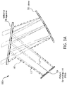
- FIGS. 3A through 5C provide additional details on the areas A1, A2, and A3.
- FIG. 2 is a cross-sectional view of a compact HUD 100 in accordance with an alternate embodiment of the HUD of FIG. 1 .
- Elements of the HUD 100 common to both FIG. 1 and FIG. 2 and which use like reference designators perform substantially the same functions. Exceptions to this are described herein.
- HUD 100 of FIG. 2 includes a display 10, a reflective polarizer 20, and mirror 30, amongst which image rays 15 (including example rays 15a, 15b, and 15c) are directed to create an appropriate optical path for displaying the emitted image to a viewer.
- image rays 15 including example rays 15a, 15b, and 15c
- quarter wave plate 25 is disposed between reflective polarizer 20 and mirror 30.
- Image rays 15 are emitted from display 10 and travel to, and are reflected by, reflective polarizer 20.
- the image rays 15 are emitted with a linear S-type polarization.
- the image rays 15 After the image rays 15 are reflected by reflective polarizer 20, they encounter and pass through quarter wave plate 25, and the polarization of image rays 15 changes from linear S-type to circular polarization. The image rays 15 are then reflected by mirror 30 and pass through quarter wave plate 25 a second time, this time changing from circular polarization to linear P-type polarization, which is substantially transmitted through reflective polarizer 20.
- using a single quarter wave plate 25 may reduce system costs, and may contribute to decreasing HUD volume.
- FIGS. 3A-3C depict simplified cross-sectional illustrations of HUD 100 of FIGS. 1 and 2 , defining several cross-sectional regions defined by subsets of image rays traveling through the HUD.
- FIG. 3A shows example region R1, shown outlined by a dashed line, wherein the region is defined by those portions of emitted image rays 15 that pass at least once across the R1 region.
- "one-pass" region R1 is a two-dimensional, cross-sectional representation of a larger three-dimensional volume that would be defined by a first pass of image rays 15 through an actual HUD 100.
- FIG. 3B shows example region R2, shown outlined by a dashed line, wherein the region R2 is defined by those portions of emitted image rays 15 that pass at least twice across the R2 region.
- region R2 is a sub-region of region R1, defining only the region where image rays have passed at least twice through that region.
- FIG. 3C shows example region R3, shown outlined by a dashed line, wherein the region R3 is defined by those portions of emitted image rays 15 that pass at least three times across the R3 region.
- region R3 is a sub-region of both regions R1 and R2, defining only the region where image rays have passed three times through that region.
- Regions R1, R2, and R3 have respective areas A1, A2, and A3.
- FIG. 4 illustrates the relationship of areas A1, A2, and A3 as defined for the example HUD 100 of FIG. 1 , contained and overset in a single drawing.
- FIGS. 5A-5C separate the three areas and displays them side by side for the purposes of comparison. By comparing the ratio of areas, and, in particular, the ratio of A3 to A1, one can create a quantitative measure of the relative amount of "area sharing" defined by the system.
- the size of area A2 represents the portion of area A1 that is shared by first-pass image rays and second-pass image rays
- the size of area A3 represents the portion of area A1 that is shared by first-pass, second-pass, and third-pass image rays.
- the larger area A3 is relative to areas A2 and A1, the less "new" area needs to be consumed by the reflected image rays.
- the relative positions and orientations of the HUD components e.g., display, reflective polarizer, and mirror
- the relative positions and orientations of the HUD components may be chosen so as to maximize the ratio of A3 to A2, and/or of A3 to A1, increasing the amount of volumetric space used to contain multiple passes of the images rays through the HUD.
- the resolution and performance of an optical system such as a HUD can be characterized using a modulation transfer function.
- the modulation transfer function provides a measurement of the HUD's ability to transfer image contrast information (or image detail) from the original displayed image to the viewer as a virtual image at a specific resolution.
- a graph showing the MTF for an optical system typically has two axes, with the MTF plotted on the vertical axis (y axis) and spatial frequency plotted along the horizontal axis (x axis).
- the MTF is a number ranging from 0.0 (no detail is transferred) to 1.0 (maximum detail transferred, the ideal case).
- FIGS. 6-9 provide graphs plotting the MTF for a compact HUD according to embodiments described herein using various shapes of mirrors and values for the first incident angle, ⁇ i1 .
- FIG. 6 a graph plotting the MTF for a compact HUD using a spherical mirror and a reflective polarizer mounted such that the first incident angle, ⁇ i1 , is approximately 55 degrees is shown.
- the graph contains lines representing the MTF values measured at each of several points of the image display, with each curve on the graph showing the values measured at a specific point for spatial frequencies from 0 to 40 cycles/mm. Coordinates used for the measured display are as follows:
- FIG. 7 is a graph plotting the MTF for a compact HUD using a free-form mirror with a reflective polarizer mounted to have a ⁇ i1 of 55 degrees in accordance with an embodiment described herein.
- Line 40b of FIG. 7 corresponds to the lower left corner of the display at (-5.0, -2.5), and line 50b corresponds to the upper right corner of the display at (5.0, 2.5).
- an image having a spatial frequency of about 4 line pairs (cycles) per mm emitted from a corner of a display within the HUD, magnified by the optical system, and transmitted by the reflective polarizer as a virtual image for viewing by a viewer should have a tangential MTF greater than about 0.8.
- the same emitted image having a spatial frequency of about 12 line pairs (cycles) per mm and being transmitted through the HUD and reflective polarizer to be viewed by a viewer, should have a tangential MTF greater than about 0.5.
- FIGS. 8 and 9 provide another example of MTF values for spherical mirrors versus free-form mirrors.
- FIG. 8 plots the MTF for a compact HUD using a spherical mirror with a reflective polarizer mounted with a first incident angle, ⁇ i1 , of 30 degrees.
- Line 40c of FIG. 8 corresponds to the lower left corner of the display at (-5.0, -2.5), and line 50c corresponds to the upper right corner of the display at (5.0, 2.5).
- FIG. 9 plots the MTF for a compact HUD using a free-form mirror with a reflective polarizer mounted with a first incident angle, ⁇ i1 , of 30 degrees.
- Line 40d of FIG. 9 corresponds to the lower left corner of the display at (-5.0, -2.5), and line 50d corresponds to the upper right corner of the display at (5.0, 2.5).
- FIGS. 8 and 9 show an overall increase in MTF when a free-form mirror is used over a spherical mirror, and a significantly reduced difference between the MTF values of the diagonally opposite corners.
- an image having a spatial frequency of about 10 line pairs (cycles) per mm emitted from a corner of a display within the HUD, magnified by the optical system, and transmitted by the reflective polarizer as a virtual image for viewing by a viewer should have a tangential MTF greater than about 0.6.
- the same emitted image having a spatial frequency of about 18 line pairs (cycles) per mm and being transmitted through the HUD and reflective polarizer to be viewed by a viewer, should have a tangential MTF greater than about 0.3.
- FIG. 10 is a chart depicting the ratio of 3-path area to 2-path area for a compact HUD in accordance with an embodiment as described herein for various values of ⁇ i1 . That is, line 60 on the graph of FIG. 10 plots the result of dividing the total 3-path area by the total 2-path area in an example HUD as a percentage over a range of various first incident angles ( ⁇ i1 ) for the reflective polarizer.
- FIG. 11 is a chart depicting the ratio of 3-path area to 1-path area for a compact HUD for various values of ⁇ i1 . That is, line 65 in FIG.
- substantially aligned will mean aligned to within 20% of a width of the objects being aligned.
- Objects described as substantially aligned may, in some embodiments, be aligned to within 10% or to within 5% of a width of the objects being aligned.
Landscapes
- Physics & Mathematics (AREA)
- General Physics & Mathematics (AREA)
- Optics & Photonics (AREA)
- Nonlinear Science (AREA)
- Mathematical Physics (AREA)
- Chemical & Material Sciences (AREA)
- Crystallography & Structural Chemistry (AREA)
- Instrument Panels (AREA)
- Polarising Elements (AREA)
Applications Claiming Priority (2)
| Application Number | Priority Date | Filing Date | Title |
|---|---|---|---|
| US201862783648P | 2018-12-21 | 2018-12-21 | |
| PCT/IB2019/060933 WO2020128841A1 (en) | 2018-12-21 | 2019-12-17 | Compact heads-up display |
Publications (2)
| Publication Number | Publication Date |
|---|---|
| EP3899643A1 EP3899643A1 (en) | 2021-10-27 |
| EP3899643B1 true EP3899643B1 (en) | 2023-01-25 |
Family
ID=69159838
Family Applications (1)
| Application Number | Title | Priority Date | Filing Date |
|---|---|---|---|
| EP19835776.6A Active EP3899643B1 (en) | 2018-12-21 | 2019-12-17 | Compact heads-up display |
Country Status (4)
| Country | Link |
|---|---|
| US (1) | US12025797B2 (https=) |
| EP (1) | EP3899643B1 (https=) |
| JP (1) | JP7539383B2 (https=) |
| WO (1) | WO2020128841A1 (https=) |
Families Citing this family (6)
| Publication number | Priority date | Publication date | Assignee | Title |
|---|---|---|---|---|
| WO2020243939A1 (en) * | 2019-06-06 | 2020-12-10 | 3M Innovative Properties Company | Compact heads-up display |
| WO2021152480A1 (en) | 2020-01-31 | 2021-08-05 | 3M Innovative Properties Company | Polarization beam splitter and hot mirror for heads up display |
| US11940639B2 (en) * | 2020-03-25 | 2024-03-26 | Magic Leap, Inc. | Optical device with one-way mirror |
| US20230384500A1 (en) | 2020-10-21 | 2023-11-30 | 3M Innovative Properties Company | Ultraviolet-stable optical films |
| WO2022215364A1 (ja) * | 2021-04-08 | 2022-10-13 | ソニーグループ株式会社 | 波長選択性位相差素子および投射型表示装置 |
| CN117203566A (zh) * | 2021-04-30 | 2023-12-08 | 3M创新有限公司 | 改善的紧凑型平视显示器 |
Citations (2)
| Publication number | Priority date | Publication date | Assignee | Title |
|---|---|---|---|---|
| DE102014211339A1 (de) * | 2014-06-13 | 2015-12-17 | Continental Automotive Gmbh | Head-Up-Display mit polarisationsselektiven optischen Pfaden |
| US20170235136A1 (en) * | 2016-02-12 | 2017-08-17 | Lg Electronics Inc. | Head up display for vehicle |
Family Cites Families (13)
| Publication number | Priority date | Publication date | Assignee | Title |
|---|---|---|---|---|
| US5882774A (en) | 1993-12-21 | 1999-03-16 | Minnesota Mining And Manufacturing Company | Optical film |
| JP2004226469A (ja) | 2003-01-20 | 2004-08-12 | Denso Corp | 車両用ヘッドアップディスプレイ装置 |
| JP5223452B2 (ja) * | 2008-05-20 | 2013-06-26 | 株式会社リコー | プロジェクタ及び投影画像形成方法及び車両用ヘッドアップディスプレイ装置 |
| US9494794B2 (en) | 2014-09-02 | 2016-11-15 | Ostendo Technologies, Inc. | Split exit pupil heads-up display systems and methods |
| WO2016038767A1 (ja) * | 2014-09-08 | 2016-03-17 | パナソニックIpマネジメント株式会社 | ヘッドアップディスプレイ及び移動体 |
| EP3006988B1 (en) | 2014-10-07 | 2022-11-30 | Ricoh Company, Ltd. | Image display apparatus |
| JP6710017B2 (ja) * | 2014-10-07 | 2020-06-17 | 株式会社リコー | 画像表示装置 |
| JP6579319B2 (ja) | 2014-11-12 | 2019-09-25 | 日本精機株式会社 | ヘッドアップディスプレイ装置 |
| JPWO2016147570A1 (ja) | 2015-03-19 | 2018-01-11 | パナソニックIpマネジメント株式会社 | ヘッドアップディスプレイ |
| US9823472B2 (en) * | 2015-07-17 | 2017-11-21 | Lg Electronics Inc. | Head up display for vehicle |
| JP2018036501A (ja) | 2016-08-31 | 2018-03-08 | パイオニア株式会社 | 虚像表示装置 |
| JP2018077435A (ja) | 2016-11-11 | 2018-05-17 | アイシン・エィ・ダブリュ株式会社 | 虚像表示装置 |
| CN108873351A (zh) | 2018-08-06 | 2018-11-23 | 中山市众盈光学有限公司 | 一种用于车载抬头显示装置的横向离轴三反光学系统 |
-
2019
- 2019-12-17 EP EP19835776.6A patent/EP3899643B1/en active Active
- 2019-12-17 JP JP2021535522A patent/JP7539383B2/ja active Active
- 2019-12-17 US US17/414,653 patent/US12025797B2/en active Active
- 2019-12-17 WO PCT/IB2019/060933 patent/WO2020128841A1/en not_active Ceased
Patent Citations (2)
| Publication number | Priority date | Publication date | Assignee | Title |
|---|---|---|---|---|
| DE102014211339A1 (de) * | 2014-06-13 | 2015-12-17 | Continental Automotive Gmbh | Head-Up-Display mit polarisationsselektiven optischen Pfaden |
| US20170235136A1 (en) * | 2016-02-12 | 2017-08-17 | Lg Electronics Inc. | Head up display for vehicle |
Also Published As
| Publication number | Publication date |
|---|---|
| EP3899643A1 (en) | 2021-10-27 |
| WO2020128841A1 (en) | 2020-06-25 |
| US20220057632A1 (en) | 2022-02-24 |
| US12025797B2 (en) | 2024-07-02 |
| JP7539383B2 (ja) | 2024-08-23 |
| JP2022514070A (ja) | 2022-02-09 |
Similar Documents
| Publication | Publication Date | Title |
|---|---|---|
| EP3899643B1 (en) | Compact heads-up display | |
| EP1430351B1 (en) | Flat-panel projection display | |
| CN108235739B (zh) | 使用矩形波导的孔径倍增器 | |
| EP1952189B1 (en) | Display with image-guiding substrate | |
| JP4395802B2 (ja) | 画像表示装置 | |
| JP2003502710A (ja) | 頭部装着式表示装置 | |
| US7023592B2 (en) | Band-pass filter and image display apparatus | |
| US12554130B2 (en) | Compact heads-up display | |
| WO2019097695A1 (ja) | 表示装置 | |
| CN218995792U (zh) | 显示装置、抬头显示器及交通设备 | |
| EP0710865A1 (en) | Optical collimating device | |
| US20250231406A1 (en) | Compact Projector for Display System | |
| JPH08136856A (ja) | 光コリメート装置および方法 | |
| JP3960733B2 (ja) | 画像投影装置 | |
| CN118339823A (zh) | 用于显示系统的紧凑型投影仪 | |
| ZA200400950B (en) | Flat-panel projection display. |
Legal Events
| Date | Code | Title | Description |
|---|---|---|---|
| STAA | Information on the status of an ep patent application or granted ep patent |
Free format text: STATUS: UNKNOWN |
|
| STAA | Information on the status of an ep patent application or granted ep patent |
Free format text: STATUS: THE INTERNATIONAL PUBLICATION HAS BEEN MADE |
|
| PUAI | Public reference made under article 153(3) epc to a published international application that has entered the european phase |
Free format text: ORIGINAL CODE: 0009012 |
|
| STAA | Information on the status of an ep patent application or granted ep patent |
Free format text: STATUS: REQUEST FOR EXAMINATION WAS MADE |
|
| 17P | Request for examination filed |
Effective date: 20210610 |
|
| AK | Designated contracting states |
Kind code of ref document: A1 Designated state(s): AL AT BE BG CH CY CZ DE DK EE ES FI FR GB GR HR HU IE IS IT LI LT LU LV MC MK MT NL NO PL PT RO RS SE SI SK SM TR |
|
| DAV | Request for validation of the european patent (deleted) | ||
| DAX | Request for extension of the european patent (deleted) | ||
| GRAP | Despatch of communication of intention to grant a patent |
Free format text: ORIGINAL CODE: EPIDOSNIGR1 |
|
| STAA | Information on the status of an ep patent application or granted ep patent |
Free format text: STATUS: GRANT OF PATENT IS INTENDED |
|
| INTG | Intention to grant announced |
Effective date: 20220809 |
|
| GRAS | Grant fee paid |
Free format text: ORIGINAL CODE: EPIDOSNIGR3 |
|
| GRAA | (expected) grant |
Free format text: ORIGINAL CODE: 0009210 |
|
| STAA | Information on the status of an ep patent application or granted ep patent |
Free format text: STATUS: THE PATENT HAS BEEN GRANTED |
|
| AK | Designated contracting states |
Kind code of ref document: B1 Designated state(s): AL AT BE BG CH CY CZ DE DK EE ES FI FR GB GR HR HU IE IS IT LI LT LU LV MC MK MT NL NO PL PT RO RS SE SI SK SM TR |
|
| REG | Reference to a national code |
Ref country code: GB Ref legal event code: FG4D |
|
| REG | Reference to a national code |
Ref country code: CH Ref legal event code: EP |
|
| REG | Reference to a national code |
Ref country code: DE Ref legal event code: R096 Ref document number: 602019024914 Country of ref document: DE |
|
| REG | Reference to a national code |
Ref country code: AT Ref legal event code: REF Ref document number: 1546280 Country of ref document: AT Kind code of ref document: T Effective date: 20230215 Ref country code: IE Ref legal event code: FG4D |
|
| REG | Reference to a national code |
Ref country code: LT Ref legal event code: MG9D |
|
| REG | Reference to a national code |
Ref country code: NL Ref legal event code: MP Effective date: 20230125 |
|
| REG | Reference to a national code |
Ref country code: AT Ref legal event code: MK05 Ref document number: 1546280 Country of ref document: AT Kind code of ref document: T Effective date: 20230125 |
|
| PG25 | Lapsed in a contracting state [announced via postgrant information from national office to epo] |
Ref country code: NL Free format text: LAPSE BECAUSE OF FAILURE TO SUBMIT A TRANSLATION OF THE DESCRIPTION OR TO PAY THE FEE WITHIN THE PRESCRIBED TIME-LIMIT Effective date: 20230125 |
|
| PG25 | Lapsed in a contracting state [announced via postgrant information from national office to epo] |
Ref country code: RS Free format text: LAPSE BECAUSE OF FAILURE TO SUBMIT A TRANSLATION OF THE DESCRIPTION OR TO PAY THE FEE WITHIN THE PRESCRIBED TIME-LIMIT Effective date: 20230125 Ref country code: PT Free format text: LAPSE BECAUSE OF FAILURE TO SUBMIT A TRANSLATION OF THE DESCRIPTION OR TO PAY THE FEE WITHIN THE PRESCRIBED TIME-LIMIT Effective date: 20230525 Ref country code: NO Free format text: LAPSE BECAUSE OF FAILURE TO SUBMIT A TRANSLATION OF THE DESCRIPTION OR TO PAY THE FEE WITHIN THE PRESCRIBED TIME-LIMIT Effective date: 20230425 Ref country code: LV Free format text: LAPSE BECAUSE OF FAILURE TO SUBMIT A TRANSLATION OF THE DESCRIPTION OR TO PAY THE FEE WITHIN THE PRESCRIBED TIME-LIMIT Effective date: 20230125 Ref country code: LT Free format text: LAPSE BECAUSE OF FAILURE TO SUBMIT A TRANSLATION OF THE DESCRIPTION OR TO PAY THE FEE WITHIN THE PRESCRIBED TIME-LIMIT Effective date: 20230125 Ref country code: HR Free format text: LAPSE BECAUSE OF FAILURE TO SUBMIT A TRANSLATION OF THE DESCRIPTION OR TO PAY THE FEE WITHIN THE PRESCRIBED TIME-LIMIT Effective date: 20230125 Ref country code: ES Free format text: LAPSE BECAUSE OF FAILURE TO SUBMIT A TRANSLATION OF THE DESCRIPTION OR TO PAY THE FEE WITHIN THE PRESCRIBED TIME-LIMIT Effective date: 20230125 Ref country code: AT Free format text: LAPSE BECAUSE OF FAILURE TO SUBMIT A TRANSLATION OF THE DESCRIPTION OR TO PAY THE FEE WITHIN THE PRESCRIBED TIME-LIMIT Effective date: 20230125 |
|
| PG25 | Lapsed in a contracting state [announced via postgrant information from national office to epo] |
Ref country code: SE Free format text: LAPSE BECAUSE OF FAILURE TO SUBMIT A TRANSLATION OF THE DESCRIPTION OR TO PAY THE FEE WITHIN THE PRESCRIBED TIME-LIMIT Effective date: 20230125 Ref country code: PL Free format text: LAPSE BECAUSE OF FAILURE TO SUBMIT A TRANSLATION OF THE DESCRIPTION OR TO PAY THE FEE WITHIN THE PRESCRIBED TIME-LIMIT Effective date: 20230125 Ref country code: IS Free format text: LAPSE BECAUSE OF FAILURE TO SUBMIT A TRANSLATION OF THE DESCRIPTION OR TO PAY THE FEE WITHIN THE PRESCRIBED TIME-LIMIT Effective date: 20230525 Ref country code: GR Free format text: LAPSE BECAUSE OF FAILURE TO SUBMIT A TRANSLATION OF THE DESCRIPTION OR TO PAY THE FEE WITHIN THE PRESCRIBED TIME-LIMIT Effective date: 20230426 Ref country code: FI Free format text: LAPSE BECAUSE OF FAILURE TO SUBMIT A TRANSLATION OF THE DESCRIPTION OR TO PAY THE FEE WITHIN THE PRESCRIBED TIME-LIMIT Effective date: 20230125 |
|
| P01 | Opt-out of the competence of the unified patent court (upc) registered |
Effective date: 20230817 |
|
| REG | Reference to a national code |
Ref country code: DE Ref legal event code: R097 Ref document number: 602019024914 Country of ref document: DE |
|
| PG25 | Lapsed in a contracting state [announced via postgrant information from national office to epo] |
Ref country code: SM Free format text: LAPSE BECAUSE OF FAILURE TO SUBMIT A TRANSLATION OF THE DESCRIPTION OR TO PAY THE FEE WITHIN THE PRESCRIBED TIME-LIMIT Effective date: 20230125 Ref country code: RO Free format text: LAPSE BECAUSE OF FAILURE TO SUBMIT A TRANSLATION OF THE DESCRIPTION OR TO PAY THE FEE WITHIN THE PRESCRIBED TIME-LIMIT Effective date: 20230125 Ref country code: EE Free format text: LAPSE BECAUSE OF FAILURE TO SUBMIT A TRANSLATION OF THE DESCRIPTION OR TO PAY THE FEE WITHIN THE PRESCRIBED TIME-LIMIT Effective date: 20230125 Ref country code: DK Free format text: LAPSE BECAUSE OF FAILURE TO SUBMIT A TRANSLATION OF THE DESCRIPTION OR TO PAY THE FEE WITHIN THE PRESCRIBED TIME-LIMIT Effective date: 20230125 Ref country code: CZ Free format text: LAPSE BECAUSE OF FAILURE TO SUBMIT A TRANSLATION OF THE DESCRIPTION OR TO PAY THE FEE WITHIN THE PRESCRIBED TIME-LIMIT Effective date: 20230125 |
|
| PG25 | Lapsed in a contracting state [announced via postgrant information from national office to epo] |
Ref country code: SK Free format text: LAPSE BECAUSE OF FAILURE TO SUBMIT A TRANSLATION OF THE DESCRIPTION OR TO PAY THE FEE WITHIN THE PRESCRIBED TIME-LIMIT Effective date: 20230125 |
|
| PLBE | No opposition filed within time limit |
Free format text: ORIGINAL CODE: 0009261 |
|
| STAA | Information on the status of an ep patent application or granted ep patent |
Free format text: STATUS: NO OPPOSITION FILED WITHIN TIME LIMIT |
|
| 26N | No opposition filed |
Effective date: 20231026 |
|
| PG25 | Lapsed in a contracting state [announced via postgrant information from national office to epo] |
Ref country code: SI Free format text: LAPSE BECAUSE OF FAILURE TO SUBMIT A TRANSLATION OF THE DESCRIPTION OR TO PAY THE FEE WITHIN THE PRESCRIBED TIME-LIMIT Effective date: 20230125 |
|
| PG25 | Lapsed in a contracting state [announced via postgrant information from national office to epo] |
Ref country code: IT Free format text: LAPSE BECAUSE OF FAILURE TO SUBMIT A TRANSLATION OF THE DESCRIPTION OR TO PAY THE FEE WITHIN THE PRESCRIBED TIME-LIMIT Effective date: 20230125 |
|
| REG | Reference to a national code |
Ref country code: CH Ref legal event code: PL |
|
| PG25 | Lapsed in a contracting state [announced via postgrant information from national office to epo] |
Ref country code: LU Free format text: LAPSE BECAUSE OF NON-PAYMENT OF DUE FEES Effective date: 20231217 |
|
| PG25 | Lapsed in a contracting state [announced via postgrant information from national office to epo] |
Ref country code: MC Free format text: LAPSE BECAUSE OF FAILURE TO SUBMIT A TRANSLATION OF THE DESCRIPTION OR TO PAY THE FEE WITHIN THE PRESCRIBED TIME-LIMIT Effective date: 20230125 |
|
| GBPC | Gb: european patent ceased through non-payment of renewal fee |
Effective date: 20231217 |
|
| REG | Reference to a national code |
Ref country code: BE Ref legal event code: MM Effective date: 20231231 |
|
| PG25 | Lapsed in a contracting state [announced via postgrant information from national office to epo] |
Ref country code: MC Free format text: LAPSE BECAUSE OF FAILURE TO SUBMIT A TRANSLATION OF THE DESCRIPTION OR TO PAY THE FEE WITHIN THE PRESCRIBED TIME-LIMIT Effective date: 20230125 Ref country code: LU Free format text: LAPSE BECAUSE OF NON-PAYMENT OF DUE FEES Effective date: 20231217 |
|
| REG | Reference to a national code |
Ref country code: IE Ref legal event code: MM4A |
|
| PG25 | Lapsed in a contracting state [announced via postgrant information from national office to epo] |
Ref country code: IE Free format text: LAPSE BECAUSE OF NON-PAYMENT OF DUE FEES Effective date: 20231217 |
|
| PG25 | Lapsed in a contracting state [announced via postgrant information from national office to epo] |
Ref country code: GB Free format text: LAPSE BECAUSE OF NON-PAYMENT OF DUE FEES Effective date: 20231217 |
|
| PG25 | Lapsed in a contracting state [announced via postgrant information from national office to epo] |
Ref country code: BE Free format text: LAPSE BECAUSE OF NON-PAYMENT OF DUE FEES Effective date: 20231231 |
|
| PG25 | Lapsed in a contracting state [announced via postgrant information from national office to epo] |
Ref country code: FR Free format text: LAPSE BECAUSE OF NON-PAYMENT OF DUE FEES Effective date: 20231231 |
|
| PG25 | Lapsed in a contracting state [announced via postgrant information from national office to epo] |
Ref country code: CH Free format text: LAPSE BECAUSE OF NON-PAYMENT OF DUE FEES Effective date: 20231231 |
|
| PG25 | Lapsed in a contracting state [announced via postgrant information from national office to epo] |
Ref country code: IE Free format text: LAPSE BECAUSE OF NON-PAYMENT OF DUE FEES Effective date: 20231217 Ref country code: GB Free format text: LAPSE BECAUSE OF NON-PAYMENT OF DUE FEES Effective date: 20231217 Ref country code: FR Free format text: LAPSE BECAUSE OF NON-PAYMENT OF DUE FEES Effective date: 20231231 Ref country code: CH Free format text: LAPSE BECAUSE OF NON-PAYMENT OF DUE FEES Effective date: 20231231 Ref country code: BE Free format text: LAPSE BECAUSE OF NON-PAYMENT OF DUE FEES Effective date: 20231231 |
|
| PG25 | Lapsed in a contracting state [announced via postgrant information from national office to epo] |
Ref country code: BG Free format text: LAPSE BECAUSE OF FAILURE TO SUBMIT A TRANSLATION OF THE DESCRIPTION OR TO PAY THE FEE WITHIN THE PRESCRIBED TIME-LIMIT Effective date: 20230125 |
|
| PG25 | Lapsed in a contracting state [announced via postgrant information from national office to epo] |
Ref country code: BG Free format text: LAPSE BECAUSE OF FAILURE TO SUBMIT A TRANSLATION OF THE DESCRIPTION OR TO PAY THE FEE WITHIN THE PRESCRIBED TIME-LIMIT Effective date: 20230125 |
|
| PG25 | Lapsed in a contracting state [announced via postgrant information from national office to epo] |
Ref country code: CY Free format text: LAPSE BECAUSE OF FAILURE TO SUBMIT A TRANSLATION OF THE DESCRIPTION OR TO PAY THE FEE WITHIN THE PRESCRIBED TIME-LIMIT; INVALID AB INITIO Effective date: 20191217 |
|
| PG25 | Lapsed in a contracting state [announced via postgrant information from national office to epo] |
Ref country code: HU Free format text: LAPSE BECAUSE OF FAILURE TO SUBMIT A TRANSLATION OF THE DESCRIPTION OR TO PAY THE FEE WITHIN THE PRESCRIBED TIME-LIMIT; INVALID AB INITIO Effective date: 20191217 |
|
| PG25 | Lapsed in a contracting state [announced via postgrant information from national office to epo] |
Ref country code: TR Free format text: LAPSE BECAUSE OF FAILURE TO SUBMIT A TRANSLATION OF THE DESCRIPTION OR TO PAY THE FEE WITHIN THE PRESCRIBED TIME-LIMIT Effective date: 20230125 |
|
| PGFP | Annual fee paid to national office [announced via postgrant information from national office to epo] |
Ref country code: DE Payment date: 20251126 Year of fee payment: 7 |