EP3899514B1 - Verfahren zur bestimmung von regionalen impedanzcharakteristiken von inhomogenen proben mittels geführter elektromagnetischer felder - Google Patents
Verfahren zur bestimmung von regionalen impedanzcharakteristiken von inhomogenen proben mittels geführter elektromagnetischer felder Download PDFInfo
- Publication number
- EP3899514B1 EP3899514B1 EP19900415.1A EP19900415A EP3899514B1 EP 3899514 B1 EP3899514 B1 EP 3899514B1 EP 19900415 A EP19900415 A EP 19900415A EP 3899514 B1 EP3899514 B1 EP 3899514B1
- Authority
- EP
- European Patent Office
- Prior art keywords
- propagation
- field
- specimen
- prescribed path
- inhomogeneous
- Prior art date
- Legal status (The legal status is an assumption and is not a legal conclusion. Google has not performed a legal analysis and makes no representation as to the accuracy of the status listed.)
- Active
Links
Images


Classifications
-
- G—PHYSICS
- G01—MEASURING; TESTING
- G01N—INVESTIGATING OR ANALYSING MATERIALS BY DETERMINING THEIR CHEMICAL OR PHYSICAL PROPERTIES
- G01N27/00—Investigating or analysing materials by the use of electric, electrochemical, or magnetic means
- G01N27/02—Investigating or analysing materials by the use of electric, electrochemical, or magnetic means by investigating impedance
- G01N27/22—Investigating or analysing materials by the use of electric, electrochemical, or magnetic means by investigating impedance by investigating capacitance
- G01N27/221—Investigating or analysing materials by the use of electric, electrochemical, or magnetic means by investigating impedance by investigating capacitance by investigating the dielectric properties
-
- A—HUMAN NECESSITIES
- A61—MEDICAL OR VETERINARY SCIENCE; HYGIENE
- A61B—DIAGNOSIS; SURGERY; IDENTIFICATION
- A61B2562/00—Details of sensors; Constructional details of sensor housings or probes; Accessories for sensors
- A61B2562/02—Details of sensors specially adapted for in-vivo measurements
- A61B2562/0223—Magnetic field sensors
-
- A—HUMAN NECESSITIES
- A61—MEDICAL OR VETERINARY SCIENCE; HYGIENE
- A61B—DIAGNOSIS; SURGERY; IDENTIFICATION
- A61B2562/00—Details of sensors; Constructional details of sensor housings or probes; Accessories for sensors
- A61B2562/04—Arrangements of multiple sensors of the same type
- A61B2562/046—Arrangements of multiple sensors of the same type in a matrix array
-
- A—HUMAN NECESSITIES
- A61—MEDICAL OR VETERINARY SCIENCE; HYGIENE
- A61B—DIAGNOSIS; SURGERY; IDENTIFICATION
- A61B5/00—Measuring for diagnostic purposes; Identification of persons
- A61B5/05—Detecting, measuring or recording for diagnosis by means of electric currents or magnetic fields; Measuring using microwaves or radio waves
- A61B5/053—Measuring electrical impedance or conductance of a portion of the body
- A61B5/0536—Impedance imaging, e.g. by tomography
Definitions
- the present technology pertains to interrogation methods for determining characteristics and/or contents of subjects.
- the present technology provides interrogation methods for determining characteristics and/or contents of dielectric specimens.
- dielectric properties can be unique to individual materials and can be used to, for example, identify specific tissues or tumors, or distinguish between explosives and foodstuffs. To date, these dielectric imaging techniques have found limited use in boutique diagnostics or in specific situations that permit dielectric measurements to be made.
- the path of electric and magnetic fields through a subject (i.e. specimen) under study will vary according to the frequency or, more generally, the rate of change of the field.
- the impedance characteristics of the subject under study will determine the paths of the current-fields will be drawn into the material of lowest impedance.
- propagation will take on more ray-like behaviors, and propagation will be dominated by the material of highest propagation velocity.
- microwave tomography uses wavelengths similar to the size of the dielectric structures under study.
- waves freely propagate and take on more ray-like characteristics.
- microwave paths can be more linear through some structures, they typically do not deeply penetrate subjects (i.e. specimens) of interest-such as the human body-and can dramatically diffract, reflect, and scatter around dielectric structures, creating a more dynamic inverse scattering problem than EIT/ECT, which can be more computationally demanding.
- the impedance mismatch between differing dielectric materials severely limits non-contact measurements because the majority of measuring electromagnetic waves will reflect or refract from the specimen of interest, and wavelengths that provide reasonable spatial resolution in air (typically GHz and above) are extremely dissipative in many materials. This limitation is currently addressed by either measuring impedances through direct contact with the specimen or performing measurements in a dielectric matching media. Such constraints are not practical in many situations where throughput and disruption are concerns, such as medical trauma, security, or manufacturing applications.
- Electrical impedance tomography methods that do not require specimen contact either require intermediate media or use very short wavelengths and high powers. Electrical impedance tomography methods that do not require specimen contact but require intermediate media are described, for example, in several issued U.S. patents including: 8,010,187 , 4,135,131 , 7,164,105 , and 7,205,782 . For example, electrical impedance tomography methods that do not require specimen contact but use very short wavelengths and high powers are described, for example, in several issued U.S. patents including: 8,933,837 , 7,660,452 , and 7,664,303 .
- Capacitance measurement techniques or electrical capacitance tomography can offer advantages over impedance methods using freely propagating fields by completing a circuit between capacitor electrodes applied to the specimen. For example, methods that inherently use lower frequencies by constraining their propagation to the capacitor circuit for capacitive tomographic techniques are described, for example, in several issued U.S. patents including: 9,110,115 and 8,762,084 . Although these techniques can reduce multi path complexity and attenuation of high frequencies, they require direct specimen contact and perform poorly in large or complex structures because electric fields are drawn to regions of a highest dielectric constant, looping around low dielectric constant regions or inhomogeneities, and potentially obscuring features of interest.
- MIT Magnetic Induction Tomography
- Electromagnetic fields with linear or hard field characteristics would address these problems because they would yield tomographic data from a known and defined region. It is known that in a wave propagating in transverse electric (TE) or transverse electric and magnetic (TEM) modes, the electric fields are orthogonal to the direction of propagation. Therefore, if an electromagnetic field is propagating in a known direction and its propagation is determined to be in TE or TEM mode, linearity and direction of the electric fields can be assumed, creating a hard-field-like condition.
- TE transverse electric
- TEM transverse electric and magnetic
- a practical example of this phenomenon is a foamed polyethylene (PE) coaxial cable: a homogenous foamed PE dielectric creates a transmission line (such as an RG-59 cable) of 75 Ohms and propagation velocity (V prop ) of 83% the speed of light.
- a transmission line such as an RG-59 cable
- V prop propagation velocity
- the same structure containing the same volume of air and PE, but concentrated into regions of pure PE and pure air will have regional characteristics of 60 Ohms and 66% V prop for pure PE and 90 Ohms and 99% V prop for air. If these bifurcated regions are aligned along the direction of propagation, the differing propagation velocities will disrupt TEM behavior and the wave will encounter significant dispersion between the slower and faster dielectric components. From a measurement perspective, the line's impedance (or composite ⁇ eff ) and propagation velocity will be a complex function of the probing frequencies and the PE and air constituent geometries.
- the effective dielectric constant ⁇ eff can again become a linear function of the fraction of the constituent components such as Eq. 2 despite their bifurcation. This could be accomplished by inductively loading the center conductor of the coaxial cable to slow its velocity to match the slower solid PE constituent.
- Various embodiments of the present technology include a method for determining characteristics of a specific region within an inhomogeneous specimen by guiding propagation of electric or magnetic fields through the inhomogeneous specimen, the method comprising: (a) generating electromagnetic waveforms, the electromagnetic waveforms propagating along a prescribed path, the prescribed path defining a series of spatial regions through which fields of the electromagnetic waveforms propagate along a field of propagation; (b) guiding the field of propagation through an inhomogeneous specimen in the prescribed path; and (c) determining a measurement of the fields of the electromagnetic waveforms propagating along the prescribed path, the measurement of the fields of the electromagnetic waveforms used to determine regional characteristics of the inhomogeneous specimen and characteristics of a specific region within the inhomogeneous specimen.
- the guiding the field of propagation through the inhomogeneous specimen in the prescribed path uses a plurality of conductors, the plurality of conductors comprising a first conductor parallel to a second conductor.
- the guiding the field of propagation through the inhomogeneous specimen in the prescribed path uses a plurality of conductors, the plurality of conductors comprising an array of parallel conductor pairs.
- each pair of the array of parallel conductor pairs are opposed on opposite sides of the inhomogeneous specimen.
- each pair of the array of parallel conductor pairs are adjacent to each other on a same side of the inhomogeneous specimen.
- the guiding the field of propagation through the inhomogeneous specimen in the prescribed path uses a plurality of conductors.
- the method further comprises sequencing the electromagnetic waveforms along the prescribed path across the plurality of conductors; and creating a dynamic prescribed propagation path and a dynamic rate of electric field propagation using the sequenced electromagnetic waveforms.
- the guiding the field of propagation through the inhomogeneous specimen in the prescribed path uses a plurality of conductors, the plurality of conductors comprising an array of discrete conductors.
- the method further comprises sequencing the electromagnetic waveforms along the prescribed path across pairs of the array of discrete conductors; and creating a dynamic prescribed propagation path and a dynamic rate of field propagation using the sequenced electromagnetic waveforms.
- the method further comprises modulating the field of propagation through the inhomogeneous specimen in the prescribed path using field modulating elements, the field modulating elements comprising physical delay structures, the physical delay structures slowing a rate of the field of propagation along the prescribed path and decreasing a speed of electromagnetic waves along the prescribed path.
- the method further comprises modulating the field of propagation through the inhomogeneous specimen in the prescribed path using field modulating elements, the field modulating elements comprising electronic components, the electronic components controlling a rate of the field of propagation along the prescribed path and controlling a speed of electromagnetic waves along the prescribed path.
- the method further comprises modulating the field of propagation through the inhomogeneous specimen in the prescribed path using field modulating elements, the field modulating elements comprising active electronic components, the active electronic components generating fields to screen against parasitic effects.
- the determining the measurement of the fields of the electromagnetic waveforms propagating along the prescribed path measures one or more of: voltage, current, phase, and strength of the fields of the electromagnetic waveforms propagating along the prescribed path.
- the method further comprises determining an effective dielectric constant or relative magnetic permeability-an effective constant-of the specific region within the inhomogeneous specimen; determining whether the effective constant of the specific region within the inhomogeneous specimen is consistent with a rate of the field of propagation along the prescribed path; modulating the field of propagation along the prescribed path when the effective constant of the specific region within the inhomogeneous specimen is not consistent with the rate of the electric field propagation along the prescribed path; measuring waveforms using the field of propagation through the specific region within the inhomogeneous specimen; and determining features of the specific region within the inhomogeneous specimen using the waveforms.
- the method further comprises generating a tomograph of the inhomogeneous specimen using the features of the specific region within the inhomogeneous specimen.
- the method further comprises adjusting the determining the effective constant of the specific region within the inhomogeneous specimen using the measuring the air gap to increase accuracy of the determining the effective constant.
- the present invention creates TE, TEM, or TM-like field propagation within an inhomogeneous region under study so that an effective permittivity ( ⁇ ) and/or permeability ( ⁇ ) of the region can be accurately determined. It accomplishes this by measuring the impedance encountered by fields propagating through a region while also measuring or determining the speed at which fields propagate through the region.
- the effective permittivity or permeability of a region is derived from two measurements: an impedance, and a propagation velocity at which the impedance was measured.
- the present technology uses a transmission line-like apparatus that spatially and temporally guides propagation of electromagnetic fields through an inhomogeneous specimen while providing external measurements points that reveal the dielectric's internal structure.
- the present technology involves systems and methods to bring tractability to the dielectric impedance tomography problem by using external structures to guide the spatial propagation of electromagnetic fields, regulate their temporal velocity through a specimen, and provide a structure for external measurement on which internal dielectric features will manifest.
- a guiding external structure such as a transmission line -the same impedance mismatches that complicate tomographic methods using freely propagating fields reveal and characterize different dielectric features of the specimens because perturbations induced by these internal dielectric features are externally measured along the guiding structure.
- the present technology includes a pair of conductors or an array of conductor pairs along which an electric field propagates, with the conductors so arranged that the propagating fields between them pass through the specimen under test.
- the transmission line is driven by a radio frequency (RF) or pulse probing signal source as shown, and may or may not be terminated with a known impedance.
- RF radio frequency
- a field guiding system includes delay means for retarding the propagation of the probing signal so that the speed of propagation of the probing signal matches the speed of electromagnetic propagation within the specimen under test.
- the present technology creates TE-like propagation within an inhomogeneous dielectric region under study so that the effective dielectric constant ( ⁇ eff ) of the region can be accurately determined. It accomplishes this by measuring the impedance between two conductive elements defining a region while also measuring and/or modulating the speed at which fields propagate through the region.
- the ⁇ eff of a region is derived from two measurements: an impedance, and a propagation velocity at which the impedance was measured.
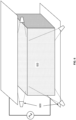
- a spatial region for study is typically defined as a columnar region between two conducting plates as shown in FIGS. 1A-C . Impedance will be measured between the two plates, and the velocity of electromagnetic propagation through the region is determined either passively, as in transmission line-based embodiments, or in active embodiments, modulated to a prescribed value. Regions may be aligned along lengths of parallel transmission lines, as shown in FIG. 2 , to spatially define the path for propagation from one region to the next, or they may be physically separate elements with a dynamically determined propagation pathway, as shown in FIG. 3 . Propagation from region to region may be a passive process as in the case of a transmission line, or an active process where phased drive circuits propagate fields from one region to the next. Regions in either active or passive embodiment may be defined over a single ground plane as shown in FIGS. 1C and 3 , with opposing elements as shown in FIG. 2 , or along a single side of a specimen as shown in FIG. 9 .
- I( ⁇ ) is the measured current at a frequency ( ⁇ ) for an excitation E( ⁇ ) across a region of A area and d length.
- E( ⁇ ) is the measured current at a frequency ( ⁇ ) for an excitation E( ⁇ ) across a region of A area and d length.
- Alternative measurements of voltage across a region or current between regions will yield similar formulations with the premise of deriving the dielectric constant of the region based on voltage and current measurements made.
- V prop ⁇ t ⁇ d
- ⁇ t is the propagation time from region to region, either as measured or as actively modulated by the system
- ⁇ d is the length of the region in the direction of propagation
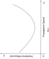
- the impedance measured within a region will vary depending on the speed at which the probing field traverses it, as illustrated in FIG. 4 .
- the impedance At the characteristic speed of the ⁇ eff , the impedance will be at a minimum. However, if the propagation speed is faster than ⁇ eff , impedance will increase, because the fields will not have time to fully interact with the slower, low-impedance dielectric components. Likewise, if the speed of propagation from region to region is too slow, impedance will also increase, because the fields from previous regions will race out from their intended region and undercut into the region ahead. In general, a region's impedance will be at a minimum when its speed is properly matched to the intrinsic velocity of electromagnetic propagation of the region.
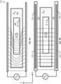
- V prop To obtain an accurate value for a region's ⁇ eff , it must be measured at multiple propagation speeds. This can be done by slowing the V prop by adding inductive, electronic, or other slowing mechanisms so that the V prop matches that of a region's slowest dielectric component, as shown in FIGS. 5A-B , to establish a TE mode. Additionally, slow wave or metamaterial structures such as electronic band-gap structures can be used to delay field propagation.
- FIGS. 5A-B illustrate diagrammatic views 500 of propagation of electric fields at different velocities according to embodiments of the present technology.
- FIG. 5A shows propagation of an electric field through a transmission line running faster than a velocity of propagation in a dielectric under examination 501 (i.e., specimen), having dielectric constant ⁇ sp , thus obscuring an internal feature of the specimen 502, having dielectric constant ⁇ ⁇ ⁇ sp .
- FIG. 5A shows propagation of an electric field through a transmission line running faster than a velocity of propagation in a dielectric under examination 501 (i.e., specimen), having dielectric constant ⁇ sp , thus obscuring an internal feature of the specimen 502, having dielectric constant ⁇ ⁇ ⁇ sp .
- FIG. 501 i.e., specimen
- FIG. 5B shows propagation of an electric field when a transmission line is slowed to accommodate an effective dielectric constant of a specimen, an internal feature of the specimen, and a surrounding air gap, thus, allowing the electric field a representative interaction with the dielectric.
- the wave front through a specimen is slowed by distributed inductive elements 505 to accommodate the ⁇ eff of the specimen, an internal feature, and a surrounding air gap 510, thereby creating a TE-like propagation mode and gaining a more fulsome and representative field interaction with the dielectric.
- a transmission line's C tl 0 is a function of line geometry and the ⁇ of its internal dielectric.
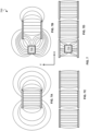
- FIGS. 7A-D illustrates diagrammatic views 700 of electric fields and regions measured for various screened and unscreened transmission lines according to embodiments of the present technology.
- FIG. 7A shows an unscreened transmission line
- FIG. 7B shows an unscreened transmission line with an outside high ⁇ r feature 705
- FIG. 7C shows a screened central transmission line
- FIG. 7D shows a screened central transmission line with an inside high ⁇ r feature 710, according to embodiments of the present technology.
- FIG. 7A-D show electromagnetic waves propagating on lines parallel to either side of a given line, which provide fields that screen or restrict the x-axis spread of a central line's fields, thereby creating a narrower or more focused region in the central line's x-axis.
- FIG. 7A shows an electric field (and equivalently the region measured) in an unscreened line.
- FIG. 7B shows an unscreened line with the outside high ⁇ r feature 705.
- FIG. 7C shows fields in a central line screened by parallel counterparts.
- FIG. 7D shows unperturbed fields of a central line screened by parallel counterparts, one of which contains the inside high ⁇ r feature 710 between the parallel counterparts.
- FIG. 8 illustrates a diagrammatic view of a system 800 that includes a transmission line with screening plates driven by active followers according to embodiments of the present technology.
- FIG. 8 shows system 800 comprising a guide structure 805 and screening plates driven by active followers.
- active components e.g., active voltage follower 810 measure the voltage along the line as it changes with the propagation of a wave, and drive a plate (e.g., screening plate 815) or other radiating element to oppose fields radiating from the line in an undesirable direction.
- the electric field modulating elements that determine the rate of electric field propagation along the prescribed path may comprise electronic components, the electronic components controlling the rate of electric field propagation along the prescribed path and controlling a speed of electromagnetic waves along the prescribed path.
- the electric field modulating elements that determine the rate of electric field propagation along the prescribed path comprise active electronic components, the active electronic components also generating electric fields to screen against parasitic effects.
- FIG. 9 illustrates a diagrammatic view of a system 900 that includes a parallel transmission line structure applied to a single surface of a specimen according to embodiments of the present technology.
- a region of characterization exists between the parallel conductors, but also extends both into the top layers of the specimen and air above the parallel lines.
- each pair of the array of parallel conductor pairs may be adjacent to each other on a same side of the inhomogeneous dielectric specimen.
- FIG. 9 further shows active screening plates 903 and 904 and driving elements 905 and 906 applied to a parallel stripline 901 and 902 to screen the extent of the region of characterization from extending into the air above the parallel lines.
- Such an embodiment is used where only one side of the specimen is accessible or only a thin or top layer of an inhomogeneous dielectric need be characterized.
- an air gap space (e.g., air gap 510) within a region but external to the specimen appears essentially the same if it were internal to the specimen.
- a surrounding air space can be readily measured through other means (e.g., physical, optical, acoustical, etc.) its impact can be readily calculated out of the region's ⁇ eff using mix equations like those of equation 2.
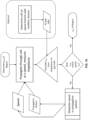
- a procedure for measurements to determine the ⁇ eff of a region is described in FIG. 10 according to embodiments of the present technology.
- Propagation speed and propagation pattern can be passively, programmatically, or actively varied to fulfill the procedure described in FIG. 10 .
- the procedure first determines a candidate ⁇ eff through measurements and calculations like those of equation 3.
- V prop V prop ⁇ 1 ⁇ eff Z the candidate ⁇ eff is too low and V prop is decreased to obtain a more accurate candidate ⁇ eff .
- the temporal and spatial pattern may be varied to optimally arrive at an optimal candidate ⁇ ff .
- a procedure might execute all possible combinations of speed and propagation pattern and then later evaluate the totality of data for the best candidate ⁇ eff .
- a passive embodiment several transmission lines are arrayed in parallel, as shown in FIG. 2 , in order to laterally define rows of regions across the span of parallel transmission lines as shown in FIG. 7C and 7D according to various embodiments. Regions are defined in the direction of propagation by points of measurement along the length of each line.
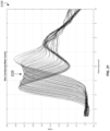
- the lines are driven by a radio frequency (RF) or pulse source probing signal and may or may not be terminated with a known impedance. As the RF or pulse signal propagates down the line, impedance changes will be revealed via voltage or current measurements on the surface of the line as shown in FIG. 11 .
- RF radio frequency
- these impedance changes will reveal the spatial location of dielectric structures, they may not fully reveal the ⁇ eff of a specific region because the structures may have induced a non-TEM mode within the line, such as that shown in FIG. 5A .
- Obtaining measurements at points along the surface of the line which reveal impedance changes may be important to resolving the spatial uncertainty that arises from merely time domain reflectometry methods, where measurements made through an end port cannot disambiguate a short section of slow velocity dielectric from a long section of high velocity dielectric.
- Passive line data at additional speeds can be obtained by inductively loading or altering an array of lines with slow wave structures as shown in FIG. 5B and equation 5.
- a further embodiment of FIG. 5B that affords a variety of propagation speeds is the array of parallel transmission lines shown in FIG. 12 . Each line is structured to have a slightly different propagation velocity. The array is mechanically passed over the specimen and impedance data for each region is gathered when scanned by each line of different velocity. Comparing impedance data from lines of various speeds as they passed over the same physical region of the specimen can identify the minimum impedance value that matches a propagation velocity per equation 6 above.
- Impedance is measured from each region of the passive embodiment via a voltage and/or current probe within the region according to various embodiments.
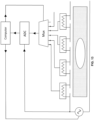
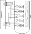
- FIG. 13 shows the hardware of a preferred embodiment using a current sensor between regions.
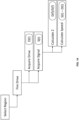
- FIG. 14 shows a process for operation using a current sensor between regions as orchestrated by a controlling computer.
- the speed and impedance data generated by a single-speed line, as illustrated in FIG. 13 may be stored by the computer for comparison against speed and impedance data from varying speed lines, such as those from FIG. 12 , to determine the optimal fit for ⁇ eff .
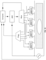
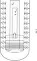
- An extension of the passive embodiment is a programmable embodiment where the inductive or delay elements between regions along a line can be altered or programmed to tune the line to a different speed, as illustrated in FIG. 15 .
- a delay element such as an inductor or programmable delay line, may be switched on or its characteristics altered as instructed by the control computer.
- the electric field modulating elements that determine the rate of electric field propagation along the prescribed path may comprise physical delay structures, the physical delay structures slowing the rate of electric field propagation along the prescribed path and decreasing a speed of electromagnetic waves along the prescribed path.
- field propagation from region to region is controlled by electronics and not free propagation as in the passive embodiment.
- Each region contains its own probing signal source controllable by a control and analyzing computer, as well as mechanisms for impedance measurement and/or waveform capture.
- the rate and direction of propagation from region to region is determined by a control and analyzing computer and may be dynamically or iteratively altered to determine a regions' ⁇ eff .
- Active regions may be defined by plates in a grid, hexagonal, arcs, or other repeating pattern as suited to the application.
- the propagation from region to region may likewise be altered to suit the application. Detection of boundaries between dielectric structures can be clearer when propagating from lower ⁇ to higher ⁇ , and propagation paths are normal to boundaries.
- a sophisticated active embodiment dynamically alters propagation paths and patterns to discern finer detail. For example, regions could propagate in one direction and then back, propagate radially or concentrically, diagonally across the scanning plane, or alternated or phased in a checkerboard pattern as shown in FIG. 18 .
- propagation may be originated and terminated at various points. Active propagation also eliminates the need for mechanical operations, such as sweeping the varied speed lines embodiment of FIG. 12 or reorienting the specimen, to gather full tomographic data.
- All embodiments generate an ⁇ eff of a columnar region which may still contain multiple dielectric components in the axis of the column. To resolve this uncertainty and generate a full tomographic rendering, data must be gathered from an orthogonal axis. In passive embodiments, this can be done by reorienting either the specimen or passive lines. In a two-sided active embodiment, alternate region axes can be obtained by tilting the regions through slight phasing of the top and bottom plates of the cell and/or creating a screening field though adjacent region plates as shown in FIG. 19 , so long as the tilted region still approximates TE in the direction of propagation.
- FIGS. 1A-C illustrate the concept of a region within which the present technology measures an effective dielectric constant ( ⁇ eff ). Impedance through the region is indicated by currents passing vertically while fields are propagating to the right as depicted in FIG. 1, FIG. 1B, and FIG. 1C illustrate this conceptual region within transmission line structures in two dimensions and three dimensions, respectively.
- the plurality of conductors for guiding the electric field propagation through the inhomogeneous dielectric specimen in the prescribed path may comprise a first conductor parallel to a second conductor.
- FIG. 2 illustrates an array of transmission line structures that define linear rows of regions along the path of propagation of each line.
- the plurality of conductors for guiding the electric field propagation through the inhomogeneous dielectric specimen in the prescribed path may comprise an array of parallel conductor pairs.
- each pair of the array of parallel conductor pairs are opposed on opposite sides of the inhomogeneous dielectric specimen.
- FIG. 3 shows a grid of metallic squares over a ground plane, each square defining a region through a dielectric specimen, illustrating a grid pattern of regions.
- the grid of FIG. 3 depicts a lumped or segmented version of the continuous lines of FIG. 2 .
- Adding connective elements between the squares in the vertical direction would allow electromagnetic fields to propagate from region to region vertically.
- Adding horizontal connective elements would allow fields to propagate horizontally, akin to the lines in FIG. 2 .
- FIG. 4 notionally illustrates the impedance measured through a region of inhomogeneous dielectric as measured at various propagation speeds. Where the propagation from region to region is too slow relative to the intrinsic speed of the dielectric, the impedance of the measured region is high due to undercutting of fields from earlier, adjacent regions. Where the propagation is fast, the impedance is again high because the fields do not have time to penetrate slower dielectric components.
- FIGS. 5A-B illustrate the field behavior of an electromagnetic wave passing through an inhomogeneous dielectric.
- the wave is moving at a velocity in excess of the propagation velocity of the slower dielectric component.
- the transmission line structure has been slowed to allow the wave to propagate in a transverse electric (TE) mode.
- TE transverse electric
- FIG. 5A propagation of an electric field through a transmission is line running faster than a velocity of propagation in a dielectric under examination, thus obscuring an internal feature of the specimen.
- FIG. 5B shows propagation of an electric field when a transmission line is slowed to accommodate an effective dielectric constant ( ⁇ ff ) of the dielectric under examination 501 (i.e., specimen), an internal feature of the specimen 502, and a surrounding air gap 510, thus allowing the electric field a representative interaction with the dielectric.
- ⁇ ff effective dielectric constant
- FIG. 6 illustrates four auxiliary sensors 600 positioned to measure air space between the region-defining structures and the subject 610 (i.e., specimen) under study.
- the auxiliary sensors may operate by radar, infrared, ultrasound, or optical/video means to quantify the amount of air space between the specimen and the region-defining structures.
- the auxiliary sensors measure an air gap between the plurality of conductors and the inhomogeneous dielectric specimen in the prescribed path.
- FIG. 10 illustrates a procedure to iteratively determine the ⁇ eff of a specific region from a measured impedance and propagation velocity.
- FIG. 11 illustrates the current through a transmission line structure as a pulse moves from region to region as measured by current-sensing elements 1100.
- FIG. 11 illustrates a diagrammatic view of measured pulse current waveforms in a system according to embodiments of the present technology.
- FIG. 11 shows pulse current waveforms 1103 as measured at points along the length of a first conductor 1105 and second conductor 1110.
- the first conductor 1105 and the second conductor 1110 encompass a specimen 1115 undergoing test that includes features of a lesser dielectric constant 1120 and features of a greater dielectric constant 1125 relative to a dielectric constant of the specimen 1115.
- FIG. 11 also shows pulse current waveforms 1103 that have a lower current illustrating a valley 1130 on the pulse current waveforms 1103 corresponding with the features of lesser dielectric constant 1120.
- pulse current waveforms 1103 have a higher voltage illustrating a peak 1135 on the pulse current waveforms 1103 corresponding with the features of greater dielectric constant 1125.
- FIG. 12 illustrates an array of transmission line structures each inductively loaded or designed to propagate at a different speed and thereby measure the impedance of a region at a different speed.
- Such an array is passed over a specimen 1200 (i.e., specimen) under study as shown by direction 1210 to measure the same region of the specimen under lines of different speeds.
- the electromagnetic waveforms along the prescribed path are sequenced across each pair of the array of parallel conductor pairs, the sequenced electromagnetic waveforms may be used to create a dynamic prescribed path for electric field propagation.
- FIG. 13 illustrates the conceptual layout of hardware along the length of a single passive transmission line. Each region is defined by current sensing elements, and each current sensing element is multiplexed with a multiplexing device (MUX) into an analog-to-digital converter (ADC) which then transmits the data into a controlling and analyzing computer.
- MUX multiplexing device
- ADC analog-to-digital converter
- FIG. 14 shows a notional sequencing that the control and analysis computer of FIG. 13 would issue. It first selects a region to be acquired with a multiplexing device, then instructs the RF source to issue the drive signal, then acquires both the signal and drive, then analyzes the data.
- FIG. 15 illustrates the conceptual layout of hardware along the length of a single programmable transmission line, similar to the passive line, but incorporating a programmable element for each region.
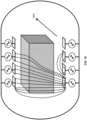
- FIG. 16 illustrates the conceptual layout of hardware of a two-dimensional section for fully active sequencing of field propagation.
- FIG. 17 illustrates the conceptual propagation of fields across a two-dimensional section of an active embodiment as the regional fields sources are sequenced from left to right.
- FIG. 18 illustrates the conceptual propagation of fields in a two-dimensional section of an active embodiment as the regional fields sources are sequenced in outward or radial patterns.
- FIG. 19 illustrates the concept of region tilting by adjusting the field producing elements in an active embodiment such that the regions are angled from the lower left to upper right as they propagate into the page in direction 1905.
- no valley or peak is shown as pulse voltage is measured in regions spanning the specimen of solid wax. The slight upward ramping of successive pulse heights is due to instrumentation error.
- pulse current waveforms are measured at points along the length of a first conductor 1105 and second conductor 1110.
- FIG. 11 also shows pulse current waveforms 1103 that have a lower current illustrating the valley 1130 on the pulse current waveforms 1103 corresponding with the features of lesser dielectric constant 1120.
- the pulse voltage waveforms of FIG. 21 show a valley 2105 indicating a water cavity of higher dielectric in the specimen for the same reasons of the valley 1130 of FIG. 11 .
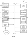
- FIG. 22 is a diagrammatic representation of an example machine in the form of a computer system 1, within which a set of instructions for causing the machine to perform any one or more of the methodologies discussed herein may be executed. For example, programming a propagation velocity or pattern to iteratively refine data.
- the machine operates as a standalone device or may be connected (e.g., networked) to other machines. In a networked deployment, the machine may operate in the capacity of a server or a client machine in a server-client network environment, or as a peer machine in a peer-to-peer (or distributed) network environment.
- the machine may be a personal computer (PC), an embedded computer, a field programmable gate array (FPGA), an application specific integrated circuit (ASIC), a tablet PC, a cellular telephone, a portable media device (e.g., a portable hard drive audio device such as an Moving Picture Experts Group Audio Layer 3 (MP3) player), a web appliance, a network router, switch or bridge, or any machine capable of executing a set of instructions (sequential or otherwise) that specify actions to be taken by that machine.
- PC personal computer
- FPGA field programmable gate array
- ASIC application specific integrated circuit
- tablet PC a cellular telephone
- portable media device e.g., a portable hard drive audio device such as an Moving Picture Experts Group Audio Layer 3 (MP3) player
- MP3 Moving Picture Experts Group Audio Layer 3
- web appliance e.g., a web appliance, a network router, switch or bridge, or any machine capable of executing a set of instructions (sequential or otherwise) that specify actions to be taken by that
- the example computer system 1 includes a processor or multiple processor(s) 5 (e.g., a central processing unit (CPU), a graphics processing unit (GPU), or both), and a main memory 10 and static memory 15, which communicate with each other via a bus 20.
- the computer system 1 may further include a video display 35 (e.g., a liquid crystal display (LCD)).
- a processor or multiple processor(s) 5 e.g., a central processing unit (CPU), a graphics processing unit (GPU), or both
- main memory 10 and static memory 15 which communicate with each other via a bus 20.
- the computer system 1 may further include a video display 35 (e.g., a liquid crystal display (LCD)).
- LCD liquid crystal display
- the computer system 1 may also include an alphanumeric input device(s) 30 (e.g., a keyboard), a cursor control device (e.g., a mouse), a voice recognition or biometric verification unit (not shown), a drive unit 37 (also referred to as disk drive unit), a signal generation device 40 (e.g., a speaker), a network interface device 45, and dielectric measurement hardware 60.
- the computer system 1 may further include a data encryption module (not shown) to encrypt data.
- the disk drive unit 37 includes a computer or machine-readable medium 50 on which is stored one or more sets of instructions and data structures (e.g., instructions 55) embodying or utilizing any one or more of the methodologies or functions described herein.
- the instructions 55 may also reside, completely or at least partially, within the main memory 10 and/or within the processor(s) 5 during execution thereof by the computer system 1.
- the main memory 10 and the processor(s) 5 may also constitute machine-readable media.
- the instructions 55 may further be transmitted or received over a network via the network interface device 45 utilizing any one of a number of well-known transfer protocols (e.g., Hyper Text Transfer Protocol (HTTP)).
- HTTP Hyper Text Transfer Protocol
- machine-readable medium 50 is shown in an example embodiment to be a single medium, the term "computer-readable medium" should be taken to include a single medium or multiple media (e.g., a centralized or distributed database and/or associated caches and servers) that store the one or more sets of instructions.
- computer-readable medium shall also be taken to include any medium that is capable of storing, encoding, or carrying a set of instructions for execution by the machine and that causes the machine to perform any one or more of the methodologies of the present application, or that is capable of storing, encoding, or carrying data structures utilized by or associated with such a set of instructions.
- the term “computer-readable medium” shall accordingly be taken to include, but not be limited to, solid-state memories, optical and magnetic media, and carrier wave signals. Such media may also include, without limitation, hard disks, floppy disks, flash memory cards, digital video disks, random access memory (RAM), read only memory (ROM), and the like.
- RAM random access memory
- ROM read only memory
- the example embodiments described herein may be implemented in an operating environment comprising software installed on a computer, in hardware, or in a combination of software and hardware.
- the Internet service may be configured to provide Internet access to one or more computing devices that are coupled to the Internet service, and that the computing devices may include one or more processors, buses, memory devices, display devices, input/output devices, and the like.
- the Internet service may be coupled to one or more databases, repositories, servers, and the like, which may be utilized in order to implement any of the embodiments of the disclosure as described herein.
- These computer program instructions may also be stored in a computer readable medium that can direct a computer, other programmable data processing apparatus, or other devices to function in a particular manner, such that the instructions stored in the computer readable medium produce an image, tomograph, or analytic product derived from said image or tomograph, or constituent data thereof including instructions which implement the function/act specified in the flowchart and/or block diagram block or blocks.
- the computer program instructions may also be loaded onto a computer, other programmable data processing apparatus, or other devices to cause a series of operational steps to be performed on the computer, other programmable apparatus or other devices to produce a computer implemented process such that the instructions which execute on the computer or other programmable apparatus provide processes for implementing the functions/acts specified in the flowchart and/or block diagram block or blocks.
Landscapes
- Chemical & Material Sciences (AREA)
- Chemical Kinetics & Catalysis (AREA)
- Electrochemistry (AREA)
- Physics & Mathematics (AREA)
- Health & Medical Sciences (AREA)
- Life Sciences & Earth Sciences (AREA)
- Analytical Chemistry (AREA)
- Biochemistry (AREA)
- General Health & Medical Sciences (AREA)
- General Physics & Mathematics (AREA)
- Immunology (AREA)
- Pathology (AREA)
- Measurement Of Resistance Or Impedance (AREA)
- Investigating Or Analyzing Materials By The Use Of Electric Means (AREA)
Claims (15)
- Verfahren zum Bestimmen von Eigenschaften eines spezifischen Bereichs innerhalb einer inhomogenen Probe durch Lenken einer Ausbreitung von elektrischen oder magnetischen Feldern durch die inhomogene Probe, das Verfahren umfassend:Erzeugen elektromagnetischer Wellenformen, wobei sich die elektromagnetischen Wellenformen entlang eines vorgeschriebenen Wegs ausbreiten, wobei der vorgeschriebene Weg eine Reihe räumlicher Bereiche definiert, durch die sich Felder der elektromagnetischen Wellenformen als ein Ausbreitungsfeld ausbreiten;Lenken des Ausbreitungsfelds durch eine inhomogene Probe auf dem vorgeschriebenen Weg; undBestimmen einer Messung der Felder der elektromagnetischen Wellenformen, die sich entlang des vorgeschriebenen Wegs ausbreiten, wobei die Messung der Felder der elektromagnetischen Wellenformen verwendet wird, um regionale Eigenschaften der inhomogenen Probe und Eigenschaften eines spezifischen Bereichs innerhalb der inhomogenen Probe zu bestimmen.
- Verfahren nach Anspruch 1, wobei das Lenken des Ausbreitungsfelds durch die inhomogene Probe auf dem vorgeschriebenen Weg eine Vielzahl von Leitern verwendet, die Vielzahl von Leitern umfassend einen ersten Leiter, der parallel zu einem zweiten Leiter verläuft.
- Verfahren nach Anspruch 1, wobei das Lenken des Ausbreitungsfelds durch die inhomogene Probe auf dem vorgeschriebenen Weg eine Vielzahl von Leitern verwendet, die Vielzahl von Leitern umfassend eine Anordnung paralleler Leiterpaare.
- Verfahren nach Anspruch 3, wobei jedes Paar der Anordnung paralleler Leiterpaare an gegenüberliegenden Seiten der inhomogenen Probe gegenüberliegt.
- Verfahren nach Anspruch 3, wobei jedes Paar der Anordnung paralleler Leiterpaare an einer gleichen Seite der inhomogenen Probe nebeneinander liegt.
- Verfahren nach Anspruch 1, wobei das Lenken des Ausbreitungsfelds durch die inhomogene Probe auf dem vorgeschriebenen Weg eine Vielzahl von Leitern verwendet;
wobei das Verfahren ferner umfasst:Sequenzialisieren der elektromagnetischen Wellenformen entlang des vorgeschriebenen Wegs über die Vielzahl von Leitern; undErstellen eines dynamischen, vorgeschriebenen Ausbreitungswegs und einer dynamischen Feldausbreitungsrate unter Verwendung der sequenzialisierten elektromagnetischen Wellenformen. - Verfahren nach Anspruch 1, wobei das Lenken des Ausbreitungsfelds durch die inhomogene Probe auf dem vorgeschriebenen Weg eine Vielzahl von Leitern verwendet, die Vielzahl von Leitern umfassend eine Anordnung diskreter Leiter.
- Verfahren nach Anspruch 7, ferner umfassend:Sequenzialisieren der elektromagnetischen Wellenformen entlang des vorgeschriebenen Wegs über Paare der Anordnung diskreter Leiter; undErstellen eines dynamischen, vorgeschriebenen Ausbreitungswegs und einer dynamischen Feldausbreitungsrate unter Verwendung der sequenzialisierten elektromagnetischen Wellenformen.
- Verfahren nach Anspruch 1, ferner umfassend
Modulieren des Ausbreitungsfelds durch die inhomogene Probe auf dem vorgeschriebenen Weg unter Verwendung von Feldmodulationselementen, die Feldmodulationselemente umfassend physikalische Verzögerungsstrukturen, wobei die physikalischen Verzögerungsstrukturen eine Rate des Ausbreitungsfelds entlang des vorgeschriebenen Wegs verlangsamen und eine Geschwindigkeit elektromagnetischer Wellen entlang des vorgeschriebenen Wegs verringern. - Verfahren nach Anspruch 1, ferner umfassend:
Modulieren des Ausbreitungsfelds durch die inhomogene Probe auf dem vorgeschriebenen Weg unter Verwendung von Feldmodulationselementen, die Feldmodulationselemente umfassend elektronische Komponenten, wobei die elektronischen Komponenten eine Rate des Ausbreitungsfelds entlang des vorgeschriebenen Wegs steuern und eine Geschwindigkeit elektromagnetischer Wellen entlang des vorgeschriebenen Wegs steuern. - Verfahren nach Anspruch 1, ferner umfassend:
Modulieren des Ausbreitungsfelds durch die inhomogene Probe auf dem vorgeschriebenen Weg unter Verwendung von Feldmodulationselementen, die Feldmodulationselemente umfassend aktive elektronische Komponenten, wobei die aktiven elektronischen Komponenten Felder erzeugen, um gegen parasitäre Effekte abzuschirmen. - Verfahren nach Anspruch 1, wobei das Bestimmen der Messung der Felder der elektromagnetischen Wellenformen, die sich entlang des vorgeschriebenen Wegs ausbreiten, eines oder mehrere misst von: Spannung, Strom, Phase und Stärke der elektrischen und/oder magnetischen Felder der elektromagnetischen Wellenformen, die sich entlang des vorgeschriebenen Wegs ausbreiten.
- Verfahren nach Anspruch 1, ferner umfassend:Bestimmen einer effektiven Konstante des spezifischen Bereichs innerhalb der inhomogenen Probe;Bestimmen, ob die effektive Konstante des spezifischen Bereichs innerhalb der inhomogenen Probe mit einer Rate des Ausbreitungsfelds entlang des vorgeschriebenen Wegs übereinstimmt;Modulieren des Ausbreitungsfelds entlang des vorgeschriebenen Wegs, wenn die effektive Konstante des spezifischen Bereichs innerhalb der inhomogenen Probe nicht mit der Rate Ausbreitungsfelds entlang des vorgeschriebenen Wegs übereinstimmt;Messen von Wellenformen unter Verwendung des Ausbreitungsfelds durch den spezifischen Bereich innerhalb der inhomogenen Probe; undBestimmen von Merkmalen des spezifischen Bereichs innerhalb der inhomogenen Probe unter Verwendung der Wellenformen.
- Verfahren nach Anspruch 13, ferner umfassend:
Erzeugen eines Tomogramms der inhomogenen Probe unter Verwendung der Merkmale des spezifischen Bereichs innerhalb der inhomogenen Probe. - Verfahren nach Anspruch 13, ferner umfassend:
Messen eines Luftspalts zwischen einer Vielzahl von Leitern und der inhomogenen Probe auf dem vorgeschriebenen Weg, und optional, wobei das Verfahren ferner umfasst:
Anpassen des Bestimmens der effektiven Konstante des spezifischen Bereichs innerhalb der inhomogenen Probe unter Verwendung des Messens des Luftspalts, um eine Genauigkeit des Bestimmens der effektiven Konstante zu erhöhen.
Applications Claiming Priority (4)
| Application Number | Priority Date | Filing Date | Title |
|---|---|---|---|
| US201862781846P | 2018-12-19 | 2018-12-19 | |
| US16/378,425 US10542906B2 (en) | 2018-04-25 | 2019-04-08 | Tomographic systems and methods for determining characteristics of inhomogenous specimens using guided electromagnetic fields |
| US16/718,102 US12228535B2 (en) | 2018-04-25 | 2019-12-17 | Methods for determining regional impedance characteristics of inhomogenous specimens using guided electromagnetic fields |
| PCT/US2019/067227 WO2020132099A1 (en) | 2018-12-19 | 2019-12-18 | Methods for determining regional impedance characteristics of inhomogenous specimens using guided electromagnetic fields |
Publications (4)
| Publication Number | Publication Date |
|---|---|
| EP3899514A1 EP3899514A1 (de) | 2021-10-27 |
| EP3899514A4 EP3899514A4 (de) | 2022-11-02 |
| EP3899514B1 true EP3899514B1 (de) | 2025-02-26 |
| EP3899514C0 EP3899514C0 (de) | 2025-02-26 |
Family
ID=71102310
Family Applications (1)
| Application Number | Title | Priority Date | Filing Date |
|---|---|---|---|
| EP19900415.1A Active EP3899514B1 (de) | 2018-12-19 | 2019-12-18 | Verfahren zur bestimmung von regionalen impedanzcharakteristiken von inhomogenen proben mittels geführter elektromagnetischer felder |
Country Status (3)
| Country | Link |
|---|---|
| EP (1) | EP3899514B1 (de) |
| CN (1) | CN113227773B (de) |
| WO (1) | WO2020132099A1 (de) |
Families Citing this family (3)
| Publication number | Priority date | Publication date | Assignee | Title |
|---|---|---|---|---|
| US10542906B2 (en) | 2018-04-25 | 2020-01-28 | Spectrohm, Inc. | Tomographic systems and methods for determining characteristics of inhomogenous specimens using guided electromagnetic fields |
| US12228535B2 (en) | 2018-04-25 | 2025-02-18 | Spectrohm, Inc. | Methods for determining regional impedance characteristics of inhomogenous specimens using guided electromagnetic fields |
| FR3112613A1 (fr) * | 2020-07-20 | 2022-01-21 | Universite Grenoble Alpes | Instrument et procede d’analyse d’un milieu complexe pour en determiner ses proprietes physico-chimiques |
Family Cites Families (13)
| Publication number | Priority date | Publication date | Assignee | Title |
|---|---|---|---|---|
| US4134395A (en) * | 1976-12-29 | 1979-01-16 | Biomagnetics International, Inc. | Method of using magnetic fields to conduct a screening diagnostic examination |
| US4493039A (en) * | 1980-05-06 | 1985-01-08 | President And Directors Of Georgetown University | Apparatus and method for image reproduction of materials using their magnetic and electric properties |
| GB9325189D0 (en) * | 1993-12-08 | 1994-02-09 | Unilever Plc | Methods and apparatus for electrochemical measurements |
| JP2938758B2 (ja) * | 1994-07-08 | 1999-08-25 | 株式会社日立製作所 | 金属材料の耐腐食性評価方法、高耐食合金の設計方法、金属材料の腐食状態診断方法およびプラントの運転方法 |
| US6522910B1 (en) * | 1997-09-11 | 2003-02-18 | Wisys Technology Foundation | Electrical property enhanced tomography (EPET) apparatus and method |
| JP2000121589A (ja) * | 1998-10-20 | 2000-04-28 | Mitsubishi Electric Corp | 流体の誘電率検知装置及びその検知方法 |
| GB0110298D0 (en) * | 2001-04-26 | 2001-06-20 | Plasma Antennas Ltd | Apparatus for providing a controllable signal delay along a transmission line |
| US8762084B2 (en) * | 2009-06-30 | 2014-06-24 | The University Of Connecticut | Multiple excitation capacitance polling for enhanced electronic capacitance tomography |
| US8653819B2 (en) * | 2009-09-08 | 2014-02-18 | California Institute Of Technology | Technique for performing dielectric property measurements at microwave frequencies |
| US20140283604A1 (en) * | 2012-10-26 | 2014-09-25 | The Regents Of The University Of Michigan | Three-dimensional microelectromechanical systems structure |
| EP3164880B1 (de) * | 2014-07-01 | 2019-12-04 | Atomnaut Inc. | Systeme und verfahren zur verwendung von multimodaler bildgebung zur bestimmung der struktur und der atomaren zusammensetzung von proben |
| CN104809282B (zh) * | 2015-04-21 | 2017-10-17 | 电子科技大学 | 基于金属散射体辅助的赋形场源构造方法 |
| CN206515281U (zh) * | 2017-02-10 | 2017-09-22 | 三峡大学 | 一种基于介电常数的土壤含水量测定装置 |
-
2019
- 2019-12-18 EP EP19900415.1A patent/EP3899514B1/de active Active
- 2019-12-18 WO PCT/US2019/067227 patent/WO2020132099A1/en not_active Ceased
- 2019-12-18 CN CN201980084979.6A patent/CN113227773B/zh active Active
Also Published As
| Publication number | Publication date |
|---|---|
| CN113227773B (zh) | 2024-11-12 |
| WO2020132099A1 (en) | 2020-06-25 |
| EP3899514A4 (de) | 2022-11-02 |
| EP3899514C0 (de) | 2025-02-26 |
| CN113227773A (zh) | 2021-08-06 |
| EP3899514A1 (de) | 2021-10-27 |
Similar Documents
| Publication | Publication Date | Title |
|---|---|---|
| US12310712B2 (en) | Tomographic systems for spatial and temporal control of an electromagnetic field to image a specimen having regions of different dielectric constants | |
| EP3899514B1 (de) | Verfahren zur bestimmung von regionalen impedanzcharakteristiken von inhomogenen proben mittels geführter elektromagnetischer felder | |
| US12228535B2 (en) | Methods for determining regional impedance characteristics of inhomogenous specimens using guided electromagnetic fields | |
| Hu et al. | Planar capacitive sensors–designs and applications | |
| Cui et al. | Study of resolution and super resolution in electromagnetic imaging for half-space problems | |
| US8340755B2 (en) | Electric field control device and detection device | |
| US4950897A (en) | Thermal wave sub-surface defect imaging and tomography apparatus | |
| US20110160554A1 (en) | Device and method for determining at least one characterizing parameter of multilayer body tissue | |
| Altuncu et al. | On the scattering of electromagnetic waves by bodies buried in a half-space with locally rough interface | |
| EP2321613A1 (de) | Verfahren und einrichtung zur charakterisierung der auswirkung eines hautbehandlungsmittels auf die haut | |
| Gade et al. | Relation of electromagnetic emission and crack dynamics in epoxy resin materials | |
| Mirala et al. | Detection of surface cracks in metals using time‐domain microwave non‐destructive testing technique | |
| Park | Direct sampling method for anomaly imaging from scattering parameter | |
| Islam et al. | A modified G auss‐N ewton algorithm for fast microwave imaging using near‐field probes | |
| Massa et al. | A microwave imaging method for NDE/NDT based on the SMW technique for the electromagnetic field prediction | |
| Bartolucci et al. | Modeling of a metallic truncated cone for electromagnetic capacitive sensors | |
| Kazemi et al. | Microwave near-field imaging of biological samples using a microstrip resonator probe | |
| Gaikovich | Methods and Applications of Near-Field Subsurface Diagnostics | |
| Lasemiimeni et al. | Effect of Conductivity on Beat Frequency Detection in Chirp Pulse Transmission Imaging | |
| Farina et al. | Analytical expressions for spreading resistance in lossy media and their application to the calibration of scanning microwave microscopy | |
| Rubæk et al. | Microwave tomography | |
| Mirjahanmardi | Microwave near-field imaging and material characterization | |
| Liu et al. | Verification and application of a finite-difference model for quasi-electrostatic scanning impedance imaging | |
| Marais | A permittivity measurement system for high frequency laboratories | |
| Abir et al. | High Resolution Microwave Tomographic Imaging Using Low Frequency Data and Artificial Neural Networks |
Legal Events
| Date | Code | Title | Description |
|---|---|---|---|
| STAA | Information on the status of an ep patent application or granted ep patent |
Free format text: STATUS: THE INTERNATIONAL PUBLICATION HAS BEEN MADE |
|
| PUAI | Public reference made under article 153(3) epc to a published international application that has entered the european phase |
Free format text: ORIGINAL CODE: 0009012 |
|
| STAA | Information on the status of an ep patent application or granted ep patent |
Free format text: STATUS: REQUEST FOR EXAMINATION WAS MADE |
|
| 17P | Request for examination filed |
Effective date: 20210528 |
|
| AK | Designated contracting states |
Kind code of ref document: A1 Designated state(s): AL AT BE BG CH CY CZ DE DK EE ES FI FR GB GR HR HU IE IS IT LI LT LU LV MC MK MT NL NO PL PT RO RS SE SI SK SM TR |
|
| DAV | Request for validation of the european patent (deleted) | ||
| DAX | Request for extension of the european patent (deleted) | ||
| A4 | Supplementary search report drawn up and despatched |
Effective date: 20221005 |
|
| RIC1 | Information provided on ipc code assigned before grant |
Ipc: A61B 5/0536 20210101ALN20220928BHEP Ipc: H03K 3/00 20060101ALI20220928BHEP Ipc: G01R 27/26 20060101ALI20220928BHEP Ipc: G01R 27/00 20060101ALI20220928BHEP Ipc: G01N 27/22 20060101ALI20220928BHEP Ipc: G01N 27/02 20060101AFI20220928BHEP |
|
| GRAP | Despatch of communication of intention to grant a patent |
Free format text: ORIGINAL CODE: EPIDOSNIGR1 |
|
| STAA | Information on the status of an ep patent application or granted ep patent |
Free format text: STATUS: GRANT OF PATENT IS INTENDED |
|
| RIC1 | Information provided on ipc code assigned before grant |
Ipc: A61B 5/0536 20210101ALN20241031BHEP Ipc: H03K 3/00 20060101ALI20241031BHEP Ipc: G01R 27/26 20060101ALI20241031BHEP Ipc: G01R 27/00 20060101ALI20241031BHEP Ipc: G01N 27/22 20060101ALI20241031BHEP Ipc: G01N 27/02 20060101AFI20241031BHEP |
|
| INTG | Intention to grant announced |
Effective date: 20241113 |
|
| GRAS | Grant fee paid |
Free format text: ORIGINAL CODE: EPIDOSNIGR3 |
|
| GRAA | (expected) grant |
Free format text: ORIGINAL CODE: 0009210 |
|
| STAA | Information on the status of an ep patent application or granted ep patent |
Free format text: STATUS: THE PATENT HAS BEEN GRANTED |
|
| AK | Designated contracting states |
Kind code of ref document: B1 Designated state(s): AL AT BE BG CH CY CZ DE DK EE ES FI FR GB GR HR HU IE IS IT LI LT LU LV MC MK MT NL NO PL PT RO RS SE SI SK SM TR |
|
| REG | Reference to a national code |
Ref country code: GB Ref legal event code: FG4D |
|
| REG | Reference to a national code |
Ref country code: CH Ref legal event code: EP |
|
| REG | Reference to a national code |
Ref country code: DE Ref legal event code: R096 Ref document number: 602019066665 Country of ref document: DE |
|
| REG | Reference to a national code |
Ref country code: IE Ref legal event code: FG4D |
|
| U01 | Request for unitary effect filed |
Effective date: 20250326 |
|
| U07 | Unitary effect registered |
Designated state(s): AT BE BG DE DK EE FI FR IT LT LU LV MT NL PT RO SE SI Effective date: 20250402 |
|
| PG25 | Lapsed in a contracting state [announced via postgrant information from national office to epo] |
Ref country code: RS Free format text: LAPSE BECAUSE OF FAILURE TO SUBMIT A TRANSLATION OF THE DESCRIPTION OR TO PAY THE FEE WITHIN THE PRESCRIBED TIME-LIMIT Effective date: 20250526 |
|
| PG25 | Lapsed in a contracting state [announced via postgrant information from national office to epo] |
Ref country code: PL Free format text: LAPSE BECAUSE OF FAILURE TO SUBMIT A TRANSLATION OF THE DESCRIPTION OR TO PAY THE FEE WITHIN THE PRESCRIBED TIME-LIMIT Effective date: 20250226 |
|
| PG25 | Lapsed in a contracting state [announced via postgrant information from national office to epo] |
Ref country code: ES Free format text: LAPSE BECAUSE OF FAILURE TO SUBMIT A TRANSLATION OF THE DESCRIPTION OR TO PAY THE FEE WITHIN THE PRESCRIBED TIME-LIMIT Effective date: 20250226 |
|
| PG25 | Lapsed in a contracting state [announced via postgrant information from national office to epo] |
Ref country code: IS Free format text: LAPSE BECAUSE OF FAILURE TO SUBMIT A TRANSLATION OF THE DESCRIPTION OR TO PAY THE FEE WITHIN THE PRESCRIBED TIME-LIMIT Effective date: 20250626 Ref country code: NO Free format text: LAPSE BECAUSE OF FAILURE TO SUBMIT A TRANSLATION OF THE DESCRIPTION OR TO PAY THE FEE WITHIN THE PRESCRIBED TIME-LIMIT Effective date: 20250526 |
|
| PG25 | Lapsed in a contracting state [announced via postgrant information from national office to epo] |
Ref country code: HR Free format text: LAPSE BECAUSE OF FAILURE TO SUBMIT A TRANSLATION OF THE DESCRIPTION OR TO PAY THE FEE WITHIN THE PRESCRIBED TIME-LIMIT Effective date: 20250226 |
|
| PG25 | Lapsed in a contracting state [announced via postgrant information from national office to epo] |
Ref country code: GR Free format text: LAPSE BECAUSE OF FAILURE TO SUBMIT A TRANSLATION OF THE DESCRIPTION OR TO PAY THE FEE WITHIN THE PRESCRIBED TIME-LIMIT Effective date: 20250527 |
|
| PG25 | Lapsed in a contracting state [announced via postgrant information from national office to epo] |
Ref country code: SM Free format text: LAPSE BECAUSE OF FAILURE TO SUBMIT A TRANSLATION OF THE DESCRIPTION OR TO PAY THE FEE WITHIN THE PRESCRIBED TIME-LIMIT Effective date: 20250226 |
|
| PG25 | Lapsed in a contracting state [announced via postgrant information from national office to epo] |
Ref country code: CZ Free format text: LAPSE BECAUSE OF FAILURE TO SUBMIT A TRANSLATION OF THE DESCRIPTION OR TO PAY THE FEE WITHIN THE PRESCRIBED TIME-LIMIT Effective date: 20250226 |
|
| PG25 | Lapsed in a contracting state [announced via postgrant information from national office to epo] |
Ref country code: SK Free format text: LAPSE BECAUSE OF FAILURE TO SUBMIT A TRANSLATION OF THE DESCRIPTION OR TO PAY THE FEE WITHIN THE PRESCRIBED TIME-LIMIT Effective date: 20250226 |
|
| PLBE | No opposition filed within time limit |
Free format text: ORIGINAL CODE: 0009261 |
|
| STAA | Information on the status of an ep patent application or granted ep patent |
Free format text: STATUS: NO OPPOSITION FILED WITHIN TIME LIMIT |
|
| PGFP | Annual fee paid to national office [announced via postgrant information from national office to epo] |
Ref country code: GB Payment date: 20251229 Year of fee payment: 7 |
|
| U20 | Renewal fee for the european patent with unitary effect paid |
Year of fee payment: 7 Effective date: 20251223 |
|
| 26N | No opposition filed |
Effective date: 20251127 |